EP0061735A2 - Système de commande pour variateur de vitesse à courroie en "V" - Google Patents
Système de commande pour variateur de vitesse à courroie en "V" Download PDFInfo
- Publication number
- EP0061735A2 EP0061735A2 EP82102530A EP82102530A EP0061735A2 EP 0061735 A2 EP0061735 A2 EP 0061735A2 EP 82102530 A EP82102530 A EP 82102530A EP 82102530 A EP82102530 A EP 82102530A EP 0061735 A2 EP0061735 A2 EP 0061735A2
- Authority
- EP
- European Patent Office
- Prior art keywords
- revolution speed
- engine
- continuously variable
- variable transmission
- value
- Prior art date
- Legal status (The legal status is an assumption and is not a legal conclusion. Google has not performed a legal analysis and makes no representation as to the accuracy of the status listed.)
- Granted
Links
Images


Classifications
-
- B—PERFORMING OPERATIONS; TRANSPORTING
- B60—VEHICLES IN GENERAL
- B60W—CONJOINT CONTROL OF VEHICLE SUB-UNITS OF DIFFERENT TYPE OR DIFFERENT FUNCTION; CONTROL SYSTEMS SPECIALLY ADAPTED FOR HYBRID VEHICLES; ROAD VEHICLE DRIVE CONTROL SYSTEMS FOR PURPOSES NOT RELATED TO THE CONTROL OF A PARTICULAR SUB-UNIT
- B60W10/00—Conjoint control of vehicle sub-units of different type or different function
- B60W10/04—Conjoint control of vehicle sub-units of different type or different function including control of propulsion units
- B60W10/06—Conjoint control of vehicle sub-units of different type or different function including control of propulsion units including control of combustion engines
-
- B—PERFORMING OPERATIONS; TRANSPORTING
- B60—VEHICLES IN GENERAL
- B60W—CONJOINT CONTROL OF VEHICLE SUB-UNITS OF DIFFERENT TYPE OR DIFFERENT FUNCTION; CONTROL SYSTEMS SPECIALLY ADAPTED FOR HYBRID VEHICLES; ROAD VEHICLE DRIVE CONTROL SYSTEMS FOR PURPOSES NOT RELATED TO THE CONTROL OF A PARTICULAR SUB-UNIT
- B60W10/00—Conjoint control of vehicle sub-units of different type or different function
- B60W10/04—Conjoint control of vehicle sub-units of different type or different function including control of propulsion units
-
- B—PERFORMING OPERATIONS; TRANSPORTING
- B60—VEHICLES IN GENERAL
- B60W—CONJOINT CONTROL OF VEHICLE SUB-UNITS OF DIFFERENT TYPE OR DIFFERENT FUNCTION; CONTROL SYSTEMS SPECIALLY ADAPTED FOR HYBRID VEHICLES; ROAD VEHICLE DRIVE CONTROL SYSTEMS FOR PURPOSES NOT RELATED TO THE CONTROL OF A PARTICULAR SUB-UNIT
- B60W10/00—Conjoint control of vehicle sub-units of different type or different function
- B60W10/10—Conjoint control of vehicle sub-units of different type or different function including control of change-speed gearings
- B60W10/101—Infinitely variable gearings
-
- B—PERFORMING OPERATIONS; TRANSPORTING
- B60—VEHICLES IN GENERAL
- B60W—CONJOINT CONTROL OF VEHICLE SUB-UNITS OF DIFFERENT TYPE OR DIFFERENT FUNCTION; CONTROL SYSTEMS SPECIALLY ADAPTED FOR HYBRID VEHICLES; ROAD VEHICLE DRIVE CONTROL SYSTEMS FOR PURPOSES NOT RELATED TO THE CONTROL OF A PARTICULAR SUB-UNIT
- B60W30/00—Purposes of road vehicle drive control systems not related to the control of a particular sub-unit, e.g. of systems using conjoint control of vehicle sub-units, or advanced driver assistance systems for ensuring comfort, stability and safety or drive control systems for propelling or retarding the vehicle
- B60W30/18—Propelling the vehicle
- B60W30/1819—Propulsion control with control means using analogue circuits, relays or mechanical links
-
- F—MECHANICAL ENGINEERING; LIGHTING; HEATING; WEAPONS; BLASTING
- F16—ENGINEERING ELEMENTS AND UNITS; GENERAL MEASURES FOR PRODUCING AND MAINTAINING EFFECTIVE FUNCTIONING OF MACHINES OR INSTALLATIONS; THERMAL INSULATION IN GENERAL
- F16H—GEARING
- F16H61/00—Control functions within control units of change-speed- or reversing-gearings for conveying rotary motion ; Control of exclusively fluid gearing, friction gearing, gearings with endless flexible members or other particular types of gearing
- F16H61/66—Control functions within control units of change-speed- or reversing-gearings for conveying rotary motion ; Control of exclusively fluid gearing, friction gearing, gearings with endless flexible members or other particular types of gearing specially adapted for continuously variable gearings
- F16H61/662—Control functions within control units of change-speed- or reversing-gearings for conveying rotary motion ; Control of exclusively fluid gearing, friction gearing, gearings with endless flexible members or other particular types of gearing specially adapted for continuously variable gearings with endless flexible members
- F16H61/66254—Control functions within control units of change-speed- or reversing-gearings for conveying rotary motion ; Control of exclusively fluid gearing, friction gearing, gearings with endless flexible members or other particular types of gearing specially adapted for continuously variable gearings with endless flexible members controlling of shifting being influenced by a signal derived from the engine and the main coupling
- F16H61/66263—Control functions within control units of change-speed- or reversing-gearings for conveying rotary motion ; Control of exclusively fluid gearing, friction gearing, gearings with endless flexible members or other particular types of gearing specially adapted for continuously variable gearings with endless flexible members controlling of shifting being influenced by a signal derived from the engine and the main coupling using only hydraulical and mechanical sensing or control means
-
- B—PERFORMING OPERATIONS; TRANSPORTING
- B60—VEHICLES IN GENERAL
- B60W—CONJOINT CONTROL OF VEHICLE SUB-UNITS OF DIFFERENT TYPE OR DIFFERENT FUNCTION; CONTROL SYSTEMS SPECIALLY ADAPTED FOR HYBRID VEHICLES; ROAD VEHICLE DRIVE CONTROL SYSTEMS FOR PURPOSES NOT RELATED TO THE CONTROL OF A PARTICULAR SUB-UNIT
- B60W2710/00—Output or target parameters relating to a particular sub-units
- B60W2710/06—Combustion engines, Gas turbines
- B60W2710/0644—Engine speed
-
- B—PERFORMING OPERATIONS; TRANSPORTING
- B60—VEHICLES IN GENERAL
- B60W—CONJOINT CONTROL OF VEHICLE SUB-UNITS OF DIFFERENT TYPE OR DIFFERENT FUNCTION; CONTROL SYSTEMS SPECIALLY ADAPTED FOR HYBRID VEHICLES; ROAD VEHICLE DRIVE CONTROL SYSTEMS FOR PURPOSES NOT RELATED TO THE CONTROL OF A PARTICULAR SUB-UNIT
- B60W2710/00—Output or target parameters relating to a particular sub-units
- B60W2710/10—Change speed gearings
- B60W2710/1005—Transmission ratio engaged
Definitions
- the present invention relates to a method and apparatus for controlling a continuously variable V-belt transmission.
- Power from an engine 201 is transmitted via a continuously variable transmission 202 to wheels 203.
- a fuel control lever 204 of the engine 201 is actuated by a servo motor 205
- a shift lever 206 is actuated by a servo motor 207
- a brake 208 is actuated by a servo motor 209.
- the servo motors 205, 207 and 209 are controlled by command signals 211, 212 and 213, respectively, from a speed control unit 210, and their position detecting signals 214, 215 and 216 are fed back to the speed control unit 210.
- the engine 201 is provided with an engine sensor 217 with which an oil temperature of the engine 201 and a vibration thereof are detected and signals 218 representing these informations are fed to the speed control unit 201.
- the continuously variable transmission 202 is provided with a transmission sensor 219 with which an oil pressure of the continuously variable transmission 202, an oil temperature thereof and an oil amount thereof. are detected and signals representing these informations are fed to the speed control unit 210.
- An input revolution speed to the continuously variable transmission 202 and an output revolution speed thereof are detected by revolution speed sensors 221 and 222, respectively, and these signals 223 and 224 representing these informations are fed to the speed control unit 210.
- a signal 226 produced by a shift command lever 225 which is manipulated by a driver.
- the speed control unit 210 stores a plurality of patterns of actions of the engine 201, continuously variable transmission 202 and brake 208 and also stores the optimum conditions of oil temperature and vibration of the engine 201 and the optimum conditions of oil pressure, oil temperature and oil amount of the continuously variable transmission 202, and it actuates the servo motors 205, 207 and 209 dependent upon what are stored therein and those signals generated by the above mentioned sensors so as to effect a shift control.
- the conventional control method of this kind requires a considerable numbers of sensors, such as a position detecting sensor for each of the respective servo motors, an input and output rotational speed sensor, an engine sensor and a transmission sensor, thus requiring a very expensive control apparatus to carry out this method, and another problem is in that since the speed control unit stores a plurality of patterns of actions, the control becomes necessarily complicated, thus inviting trouble, malfunction and the like.
- a predetermined function defining a desired value in engine revolution speed for any value in the parameter indicative of the output torque of the engine is used to determine a desired value in engine revolution speed for a value in the parameter.
- An object of the present invention is to provide a method and an apparatus for controlling a continuously variable transmission which require a small number of sensors, each for detecting an input variable, and less complicated in control.
- a kickdown operation is provided by setting the speed of action of a shift motor at a rate higher than that of a V-belt pulley mechanism so that upon depressing an accelerator pedal rapidly to cause a kickdown, a spool of a shift control valve which regulates fluid supply to and discharge from the cylinder chambers of a drive and a driven pulley is displaced beyond a new balanced position toward a higher reduction side before being returned back to the new balanced position as a result of movement of the pulleys to new position corresponding to the new balanced position of the spool of the shift control valve.
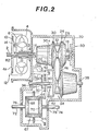
- a power transmission mechanism of a continuously variable transmission to which a shift control method according to the present invention is applied is shown in Figs. 2 and 3.
- a torque converter 12 (which may be replaced with a fluid coupling) including a pump impeller 4, a turbine runner 6, a stator 8 and a lock-up clutch (lock-up device) 10.
- the lock-up clutch 10 is connected to the turbine runner 6 in an axially slidable manner and cooperates with a member (converter shell) 4a coupled with the engine output shaft 2 integral with the pump impeller 4 to define a lock-up clutch oil chamber 14 and operates such that when the oil pressure within the lock-up clutch oil chamber 14 becomes lower than that within the interior of the torque converter 12, this difference in oil pressure urges the lock-up clutch 10 to be pressed against the member 4a to come into a unitary rotation therewith.
- the turbine runner 6 is splined to one end of a drive shaft 22 which is rotatably supported by a case 20 via bearings 16 and 18. Arranged on the drive shaft 22 between the bearings 16 and 18 is a drive pulley 24.
- the drive pulley 24 comprises an axially fixed conical disc 26 and an axially movable conical disc 30 which is disposed to face the axially fixed conical disc 26 to define a V-shaped pulley groove therebetween and which is allowed to slide in an axial direction of the driven shaft 22 in response to an oil pressure created within a drive pulley cylinder chamber 28 (see Fig. 4).
- the drive pulley 24 is drivingly connected to a driven pulley 34 via a V-belt 32, this driven pully 34 being arranged on a driven shaft 40 which is rotatably" supported by the case 20 via the bearings 36 and 38.
- the driven pulley 34 comprises an axially fixed conical disc 42 fixed to the driven shaft 40 and an axially movable conical disc 46 which is disposed to face the fixed conical disc 42 in such a manner as to define a V-shaped pulley groove and which is allowed to slide in an axial direction of the driven shaft 40 in response to an oil pressure created in a driven pulley cylinder chamber 44 (Fig. 4).
- the aixally fixed conical disc 42 is drivingly connectable via a forward drive multiple disc clutch 48 to a forward drive gear 50 rotatably supported on the driven shaft 40, this forward drive gear being in mesh with a ring gear 52.
- Fixed to the driven shaft 40 is a reverse drive gear 54 which is in mesh with an idle gear 56.
- the idle gear 56 is drivingly connectable via a reverse drive multiple disc clutch 58 to an idle shaft 60 which has fixed thereto another idle gear 62 that is in mesh with the ring gear 52.
- the idle gear 62, idle shaft 60 and reverse drive multiple disc clutch 58 are illustrated in positions displaced from the actually positions thereof for ease of illustration, the idle gear 62 and ring gear 52 are shown as out of mesh with each other, but, they are actually in mesh with each other as will be understood from Fig.
- the ring gear 52 has attached thereto a pair of pinion gears 64 and 66, output shafts 72 and 74 being coupled with side gears 68 and 70, respectively, which are in mesh with the pinion gears 64 and 66 to cooperate to form a differential 67, and the output shafts 72 and 74 which are supported via bearings 76 and 78, respectively, extending outwardly of the case 20 in the opposite directions.
- These output shafts 72 and 74 are connected to road wheels (not shown), respectively.
- Rotational power fed from the engine output shaft 2 to the continuously variable transmission is transmitted via torque converter 12, drive shaft 22, drive pulley 24, V-belt 32, driven pulley 34 to driven shaft 40 and in the case the forward multiple disc clutch 48 is engaged with the reverse drive multiple disc clutch 58 released, the rotation of the shaft 40 is transmitted via the forward drive gear 50, ring gear 52 and differential 67 to the output shafts 72 and 74 to rotate them in the forward rotational direction, whereas, in the case the reverse drive multiple disc clutch 58 is engaged with the forward drive multiple disc clutch released, the rotation of the shaft 40 is transmitted via the reverse drive gear 54, idle gear 56, idle shaft 60, idle gear 62, ring gear 52 and differential 67 to the output shafts 72 and 74 to rotate them in the reverse rotational direction.
- the rotation ratio between the drive pulley 24 and driven pulley 34 may be varied by moving the aixally movable conical disc 30 of the drive pulley 24 and the axially movable conical disc 46 of the driven pulley 34 in an axial direction so as to change the radii of the diameter contacting with the V-belt 32.
- the torque converter serves as a torque multiplier or serves as a fluid coupling but, since it has the lock-up clutch 10 as attached to the turbine runner 6, the torque converter 12 can establish a direct mechanical connection between the engine output shaft 2 and driven shaft 22 when oil pressure is drained from the lock-up clutch oil chamber 14 to press the lock-up clutch 10 against the member 4a integral with the pump impeller 4.
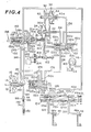
- the hydraulic pressure control system comprises an oil pump 80, line pressure regulator valve 102, a manual valve 104, shift ratio control valve 106, lock-up valve 108, shift motor 110, and a shift operating mechanism 112.
- the oil pump 80 which is driven by the engine output shaft 2 as mentioned before discharges the oil within the tank 114 into the oil conduit 116.
- the oil pump drive shaft 82 is not illustrated in Fig. 4 for the sake of simplicity of illustration.
- the oil conduit 116 leads to ports 118a and 118c of the line pressure regulator valve 102 and the oil pressure therein will be regulated into a line pressure.
- the oil conduit 116 communicates with a port 120b of the manual valve 104 and a port 122c of the control valve 106.
- the manual valve 104 has a valve bore 120 provided with five ports 120a, 120b, 120c, 102d and 120e, and a spool 124 formed with two lands 124a and 124b received in the valve bore 120, which spool 124 is actuated by a shift lever (not shown) between five detent positions "P", "R”, "N", 'D” and "L".
- the port 120a is permitted to communicate not only with a port 120d via an oil conduit 126, but also with a cylinder chamber 58a of the reverse drive multiple disc clutch 58.
- a port 120c is permitted to communicate not only with a port 120e by an oil conduit 130, but also with a cylinder chamber 48a of a forward drive multiple disc clutch 48.
- the port 120b communicates with the oil conduit 116 to receive line pressure therein.
- the port 120b supplied with the line pressure is covered by a land 124b, so that the cylinder chamber 58a of the reverse drive multiple disc clutch 58 is drained via the oil conduit 126 and port 120d and the cylinder chamber 48a of the forward drive multiple disc clutch 48 is drained via the port 120e.
- the port 120b When the.spool 124 is set in "R" position, the port 120b is permitted to communicate with the port 120a by a groove between the lands 124a and 124b so as to permit the line pressure to communicate with the cylinder chamber 58a for the reverse drive multiple disc clutch 58, whereas, the cylinder chamber 48a of the forward drive multiple disc clutch 48 is left drained via the port 120e.
- the port 120b When the spool 124 is set in "N" position, the port 120b is disposed between the lands 124a and 124b and is prevented from communicating with the other ports, thus the cylinder chamber 58a of the reverse drive multiple disc clutch 58 and the cylinder chamber 48a of the forward drive multiple disc clutch 48 are drained via the port 120a and port 120e in a similar manner to the case when the spool is in "P" position.
- the port 120b When the spool 124 is set in "D" or “L” position, the port 120b is permitted to communicate with the port 120c via the groove between the port 120b and 120c so that the line pressure is supplied to the cylinder chamber 48a of the forward multiple disc clutch 48, whereas, the cylinder chamber 58a of the reverse drive clutch 58 is drained via the port 120a.
- both the forward drive multiple disc clutch 48 and reverse drive multiple disc clutch 58 are released to interrupt the transmission of power, thus preventing the rotation of output shafts 72 and 74;
- the reverse drive multiple disc clutch 58 is engaged so as to drive the output shafts 72 and 74 in the reverse rotational direction;
- the forward drive multiple disc clutch 48 is engaged so as to drive the output shafts 72 and 74 in the forward rotational direction.
- the line pressure regulator valve 102 comprises a valve bore 118 provided with five ports 118a, 118b, 118c, 118d and 118e, a spool 132 formed with five lands 132a, 132b, 132c, 132d and 132e, and springs 134 and 136 arranged on the both ends of the spool 132. It is to be noted that the lands 132a and 132e provided on the both end portions of the spool 132 are smaller in diameter than the intermediate lands 132b, 132c and 132d.
- the left side spring 134 is disposed between the left end of the spool 132 and a throttle link 138, which throttle link 138 is urged for leftward movement as the throttle opening degree increases or for rightward movement as the throttle opening degree decreases. Therefore, if the throttle opening is great, the force created by the spring 134 urging the spool 132 rightwardly is small, whereas, if the throttle opnening degree is small, the force by the spring 134 urging the spool rightwardly is great.
- a right side spring 136 is disposed between the right end,o f the spool 132 and a rod 140 cooperating with the axially movable conical disc 30 of the drive pulley 24.
- the ports 118a and 118c of the line pressure regulator valve 102 are supplied with the output oil discharged by the oil pump 80, the inlet to the port 118a being provided with an orifice 142.
- the port 118b is always drained, the port 118d is connected by an oil conduit 144 to an inlet port 146 of the torque converter and a port 150c of the lock-up valve 108, the port 118e communicates via an oil conduit 148 with the lock-up clutch oil chamber 14 within the torque converter 12 and with a port 150b of the lock-up valve 108.
- the oil conduit 144 is provided with an orifice 145.
- Applied to the spool 134 of the line pressure regulator valve 102 are two forces in the righward direction, one by the spring 134 and the other by the line pressure acting on a differential area between the lands 132a and 132b, and two forces in the leftward direction, one by the spring 136 and the other by the pressure at the port 118e acting upon a differential area between the land 132d and 132e, and the spool 132 adjusts the amount of drainage of the oil at the ports 118c via the port 118d and 118b (firstly the oil is drained via the port 118d into the oil conduit 144, and if it cannot afford the adjustment, the oil is drained via the port 118b, too), thus regulating the line pressure to balance the forces in the leftward and rightward directions.
- the line pressure increases as the throttle opening degree increases, as a reduction ratio increases, and as the pressure at the port 118e (viz., the oil pressure building up within the lock-up clutch oil chamber 14) increases.
- the torque converter 12 is in non lock-up state because the oil pressure in the chamber 14 is high.
- the adjustment of the line pressure in this manner meets the actual demands, viz., the oil pressure must be increased to increase a force with which the pulleys are urged against the V-belt 32 so as to increase the torque transmission capacity which increases with increase in friction because the output torque of the engine increases as the throttle opening degree increases and the multiplication of the torque increases as the reduction ratio increases and besides the oil pressure must be increased to increase the transmission torque to deal with the multiplication function of the torque by the torque converter 12 when it operates in a non lock-up state prior to lock-up.
- a force due to a diaphragm device which is operative to create the force in response to an engine induction vacuum may be used instead of the force in response to the throttle opening degree.
- the setting is made such that when the induction vacuum is high the force due to the spring 134 increases, whereas, when the induction vacuum is low, the force due to the spring 134 decreases, so that a similar result to that obtained in the use of the throttle opening is obtained.
- the shift control valve 106 has a valve bore 122 formed with five ports 122a, 122b, 122c, 122d and 122e, and a spool 152 received in the valve bore 122 and formed with four lands 152a, 152b, 152c and 152d.
- the center port 122c communicates with the oil conduit 116 which is supplied with the line pressure
- the left port 122b and right port 122d communicate via respective conduits 154 and 156 with the drive pulley cylinder chamber 28 of the drive pulley 24 and the driven pulley cylinder chamber 44 of the driven pulley 34.
- the port 122b communicates via an oil conduit 158 with a port 150d of the lock-up valve 108, too.
- Both of the end ports 122a and 122e are drained.
- the left end of the spool 152 is linked to a substantially middle portion of a lever 160 of the later-mentioned shift operating mechanism 112.
- the axial length of each of the lands 152b and 152c is slightly smaller than the width of the corresponding one of the ports 122b and 122d, whereas, the axial length between the lands 152b and 152c is substantially the same as the axial length between the ports 122b and 122d.
- a portion of the line pressure supplied via the port 122c to the oil chamber between the lands 152b and 152c is allowed to pass through a clearance formed between the land 152b and the port 122b to flow into an oil conduit 154, but the remaining portion thereof is allowed to pass through another clearance formed between the land 152b and the port 122b to be drained, so that the pressure within the oil conduit 154 is determined depending upon the ratio between the areas of the above-mentioned clearances.
- the pressure within the oil conduit 156 is determined depending upon the ratio of the areas of clearances formed between the edges of the land 152c and the port 122d.
- the spool 152 is disposed in the center position, the relationship of the land 152b with the port 122b becomes equal to that of the land 152c with the port 122d, thus causing the pressure in the oil conduit 154 to become equal to that in the oil conduit 156.
- the clearance of the port 122b on the line pressure side increases and the clearance thereof on the drain side decreases, thus allowing the pressure in the oil conduit 154 to increase accordingly, whereas, the clearance of the port 122d on the line pressure side decreases and the clearance thereof on the drain side increases, thus causing the pressure in the oil conduit 156 to decrease accordingly.
- the lever 160 of the shift operating mechanism 112 which lever is pin connected at its middle portion with the spool 152 of the shift control valve 106, has its one end received in an annular groove 30a formed in the axially movable conical disc 30 of the drive pulley 24 and has its opposite end pin connected with the sleeve 162.
- the sleeve 162 is internally threaded to mesh with the thread formed on the shaft 168 which is rotatable by the shift motor 110 via the gears 164 and 166.
- the shift motor 110 is controlled by a shift control unit 300 which detects as an electric signal the revolution speed of the drive pulley 24 and the throttle opening degree, compares these detected values with a desired function, which is preset, of these variables so as to carry out a control to always accomplish desired operating condition, the control unit 300 being described later in more detail.
- the lock-up valve 108 comprises a valve bore 150 formed with four ports 150a, 150b, 150c and 150d, a spool 170 having two lands 170a and 170b, and a spring 172 biasing the spool 170 rightwardly.
- the port 150d communicates with a port 122b of the shift control valve 106 through an oil conduit 158
- the ports 150b and 150c communicate respectively through oil conduits 148 and 144 with the port 118e of the line pressure regulator valve 102 and the port 118d thereof, and the port 150a is drained.
- the oil conduits 144 and 158 and a drain oil conduit extending from the port 150a are provided with orifices 174, 176 and 178, respectively.
- the orifice 178 is provided to prevent rapid drainage of the oil pressure from the lock-up clutch oil chamber 14 so as to alleviate a shock upon shifting into lock-up state
- the orifice 174 is provided in the oil conduit 144 to permit a gradual increase in oil pressure within the lock-up oil chamber 14 so as to alleviate a shock upon release of the lock-up state
- An orifice 176 is provided in an oil conduit 158 to prevent the occurrence of a chattering in the lock-up valve 108 owing to small variation in oil pressure in the drive pulley cylinder chamber 28.
- the torque converter outlet port 180 communicates with the oil conduit 182 which is provided with a relief valve 188 including a ball 184 and a spring 186 and thus, with this relief valve, the pressure within the torque converter 12 is maintained at a constant presssure.
- the oil downstream of the relief valve 188 is -introduced by an oil conduit 190 to an oil cooler and a lubricant circuit, both being unillustrated, and is finally drained, whereas, an excessive oil is drained by another relief valve 192, the thus drained oil being returned finally to a tank 114.
- Fig. 5 is a block diagram of the shift control unit 300.
- a drive pulley revolution speed sensor 25 mounted to the drive pulley 24 generates a train of pulse signal Mp indicative of the revolution speed of the drive pulley 24 to the control unit 300, this pulse signal being shaped by a wave shaper circuit 302 and in turn converted by a F/V converter 304 into an electric voltage signal Np. Therefore, Np is proportional to the number of revolution of the drive pulley 24.
- An electric voltage signal MTH is detected which is indicative of the throttle opening degree as detected by the throttle opening degree sensor 3 provided to the carburetor portion of the engine, this signal MTH being fed to the function generating circuit 306.
- the electric voltage signal MTH is converted into an electric voltage signal NTH in accordance with a function f which is stored in the function generator circuit 306.
- the above mentioned function f provides a low limit value in the engine revolution speed vs., throttle opening degree, viz., a low limit value in the engine revolution speed at any given throttle opening degree (viz., at any value in MTH), and produce an electric voltage signal NTH indicative of such value.
- the function f may be set in a desired manner, and thus may be set to provide a value in the engine revolution speed which satisfies a minimum fuel consumption relationship of the engine revolution speed with the throttle opening degree.
- the signal Np and the signal NTH are compared with each other at a first comparator 308 and the first comparator 308 provides a 1 level signal when Np ⁇ NTH (viz., when the actual drive pulley revolution speed is lower than the desired engine revolution speed) or provides a 0 level signal when Np ⁇ NTH (viz., when the actual drive pulley revolution speed is higher than the desired engine revolution speed).
- This output signal is amplified by an amplifier 310 and then fed to a relay 110a for switching the direction of rotation of the shift motor 110, wherein the relay acts to establish a motor drive circuit to effect a positive rotation of the shift motor 110 (a rotational direction which causes an increase in reduction ratio) when it receives the 1 level signal or to effect a reverse rotation of the motor (viz., a direction which causes a reduction in reduction ratio) when it receives the 0 level signal.
- the output NTH of the function generator 306 is fed also to an adder circuit 312 where an electric voltage LiTH representing a deviation from a desired engine revolution speed is added and the result is compared with Np at a second comparator 314.
- the comparator 314 provides a 1 level signal when Np >NTH + ⁇ TH (viz., when the actual drive pulley revolution speed is higher than an upper limit value in the desired engine revolution speed) or provides a 0 level signal when Np ⁇ NTH + ⁇ TH (viz., when the drive pulley revolution speed is equal to or lower than the upper limit value in the desired engine revolution speed).
- the output of the second comparator 314 and that of the first comparator 308 are fed to a logical AND gate 316.
- the logical AND gate 316 therefore provides as an output a 0 level signal only when the output signals from the both comparators 308 and 314 are 0 level (viz., when NTH ⁇ Np ⁇ NTH + ⁇ TH), and provides a 1 level signal otherwise (viz., when Np ⁇ NTH or Np > NTH + ⁇ TH) .
- This output is amplified by a signal amplifier 318 and then fed to an ON-OFF relay 110b for the shift motor 110 so as to turn on the ON-OFF relay. 110b to actuate the shift motor 110 when it receives a 1 level signal or stop actuation of the motor when it receives a 0 level signal.
- the shift motor 110 is not actuated, thus maintaining the current reduction ratio, while, in the case Np ⁇ NTH, the shift motor 110 rotates in the positive direction to increase reduction ratio, or in the case Np NTH + ⁇ TH, the shift motor 110 rotates in the reverse direction to decrease reduction ratio, with the result that the actual drive pulley revolution speed is maintained within the desired range.
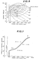
- Fig. 6 shows an engine performance of an engine.
- engine revolution speed is expressed on the axis of abscissas and engine torque on the axis of ordinates and there are shown engine torque vs., engine revolution speed characteristic curves, each for a throttle opening degree (each curve being accompanied by a throttle opening degree in Fig. 6) and there are also shown isofuel consumption rate curves FC1 ⁇ FC8 (fuel consumption rate reducing in this numerical order).
- the minimum fuel consumption rate curve G as shown by the solid line is obtained by connecting the minimum fuel consumption points. If the engine is operated to satisfy this minimum fuel consumption rate curve G, the fuel consumption rate by the engine can be made minimum.
- the minimum fuel consumption rate curve may be expressed as shown in Fig.
- the continuously variable transmission must be controlled such that if the engine revolution speed is higher than the minimum fuel consumption rate curve G such as a point A, the reduction ratio is decreased to cause an reduction in engine revolution speed, whereas, if the engine revolution speed is lower than the minimum fuel consumption rate curve G such as a point B, the reduction ratio is increased to cause an increase in engine revolution speed. If in this manner the engine is operated within a predetermined range of the minimum fuel consumption rate curve, the object of operating the engine to always satisfy the minimum fuel consumption rate is accomplished.
- the shift motor 110 is operated in the above-mentioned predetermined manner to cause the engine to operate always within the predetermined range of the above-mentioned minimum fuel consumption rate curve.
- the minimum fuel consumption rate curve is expressed in terms of throttle opening degree, it may as well be expressed in terms of induction manifold vacuum, and in the latter case, the engine performance characteristic may be expressed as shown in Fig. 8 and the minimum fuel consumption rate curve may be expressed as shown in Fig. 9.
- the previously mentioned throttle opening sensor 3 must be replaced with an induction manifold vacuum sensor. If the invention is to be applied to a diesel engine, a throttle opening degree nor an induction manifold vacuum can not be employed as an engine power output and thus in this case the a signal indicative of the fuel supply, viz-, the fuel injection amount, is used instead.
- the engine performance characteristic may be expressed as shown in Fig. 10 and the minimum fuel consumption rate curve may be expressed as shown in Fig. 11 in a similar manner to that shown in Fig. 7.
- the engine power output signal in terms of the amount of fuel injection can be obtained as an output of a sensor provided to detect the displacement of a fuel injection amount control lever or rack.
- the shift pattern diagram in the case the shift is controlled in the above mentioned manner is illustrated in Fig. 12.
- the throttle opening degree is made constant at 40 0
- the engine revolution speed is held in the neighbourhood of 3,000 r.p.m. so as to make the fuel consumption minimum (refer Fig. 6) and the vehicle speed varies from 25 Km/h to 85 Km/h.
- the reason why the shift lines exist within a region below a line L which connects the maximum reduction ratio points is that within this region the oil pressure in the oil conduit 158 is too low to actuate the lock-up control valve 108, allowing the torque converter to operate in converter state to permit full use of slip within the torque converter 12.
- the drive pulley revolution speed is detected instead of the engine revolution speed to effect the shift control because the engine revolution speed becomes higher than the drive pulley revolution speed when the torque converter operates in non lock-up state and as a torque converter, viz., during kickdown or up-climbing of a steep slope or start-up. Therefore, while the torque converter 12 operates to perform torque multiplication function, the maximum reduction ratio is kept to produce a strong traction power, and since the shift is not yet initiated, the lock-up is not effected. Once, the lock-up has been effected, the engine revolution speed agrees with drive pulley revolution speed as described above and thereafter the shift is carried to satisfy the minimum fuel consumption rate curve as shown in Fig. 7 or Fig. 9.
- the above-mentioned shift control is intended to satisfy the minimum fuel consumption rate
- another function generator circuit so as to carry out shift to satisfy the maximum torque curve of the engine so as to provide a shift pattern which enables the engine to produce the maximum accleration.
- a kickdown operation is provided by setting the speed of action of the shift motor 110 at a rate higher than that of the V-belt pulley mechanism. If the accelerator pedal is depressed rapidly to fully open the throttle valve, the MTH and NTH become maximum to satisfy NTH > Np, tending to operate the shift motor 110 in a direction to increase the reduction ratio, but this can not be followed by the actual shift operation by the V-belt pulley mechanism so that the shift motor 110 acts effectively on the shift control valve 106 to cause shift control valve 106 to move in a direction to increase the reduction ratio, viz., a state wherein the spool 152 is disposed in the rightmost position.
- an actual revolution speed of a drive pulley and a parameter indicative of-engine output torque such as a throttle opening degree,-an intake manifold vacuum and an amount of fuel supply, are detected.
- a desired value in engine revolution speed is determined for a value in the parameter using a predetermined function defining a desired value in engine revolution speed for any value in the parameter indicative of the engine output torque.
- the shift motor is operated in such a manner as to maintain the revolution speed of the drive pulley in a predetermined relationship with the desired value in engine revolution speed. It will be appreciated that because the number of sensors to be used is only two, viz., a throttle opening sensor (or an.
- the invention can be carried out at a very small cost. According to the present invention, the prospect of malfunction and trouble is very small because a very simple feed back control is used. If a function indicative of the minimum fuel consumption rate is used as the above mentioned function, an engine operates always with the minimum fuel consumption rate, thus making contribution to the fuel saving. An effective kickdown can be provided by actuating the shift motor more swiftly than the actual shift between the V-belt pulley mechanism.
Applications Claiming Priority (2)
| Application Number | Priority Date | Filing Date | Title |
|---|---|---|---|
| JP44749/81 | 1981-03-28 | ||
| JP56044749A JPS57161346A (en) | 1981-03-28 | 1981-03-28 | Speed change control method for v-belt stepless speed change gear |
Publications (3)
| Publication Number | Publication Date |
|---|---|
| EP0061735A2 true EP0061735A2 (fr) | 1982-10-06 |
| EP0061735A3 EP0061735A3 (en) | 1985-01-09 |
| EP0061735B1 EP0061735B1 (fr) | 1988-10-19 |
Family
ID=12700089
Family Applications (1)
| Application Number | Title | Priority Date | Filing Date |
|---|---|---|---|
| EP82102530A Expired EP0061735B1 (fr) | 1981-03-28 | 1982-03-25 | Système de commande pour variateur de vitesse à courroie en "V" |
Country Status (4)
| Country | Link |
|---|---|
| US (1) | US4543077A (fr) |
| EP (1) | EP0061735B1 (fr) |
| JP (1) | JPS57161346A (fr) |
| DE (1) | DE3279127D1 (fr) |
Cited By (22)
| Publication number | Priority date | Publication date | Assignee | Title |
|---|---|---|---|---|
| EP0094627A2 (fr) * | 1982-05-14 | 1983-11-23 | Nissan Motor Co., Ltd. | Procédé et dispositif pour commander une transmission variable sans interruption |
| EP0095132A1 (fr) * | 1982-05-20 | 1983-11-30 | Nissan Motor Co., Ltd. | Procédé et dispositif pour la commande d'une transmission continuellement variable |
| EP0101151A1 (fr) * | 1982-08-06 | 1984-02-22 | General Motors Corporation | Système de commande pour transmission à rapport de vitesse continuellement variable |
| EP0111891A2 (fr) * | 1982-12-17 | 1984-06-27 | Nissan Motor Co., Ltd. | Procédé de commande d'une transmission variable continûment |
| EP0117069A1 (fr) * | 1983-02-07 | 1984-08-29 | Toyota Jidosha Kabushiki Kaisha | Procédé de réglage d'une transmission à variation |
| EP0117313A2 (fr) * | 1982-12-29 | 1984-09-05 | Nissan Motor Co., Ltd. | Méthode de commande de moteur à combustion interne comprenant un réétalonnage du schéma de commande |
| EP0120460A1 (fr) * | 1983-03-26 | 1984-10-03 | Mazda Motor Corporation | Système de commande pour transmission automobile |
| EP0123083A2 (fr) * | 1983-03-11 | 1984-10-31 | Nissan Motor Co., Ltd. | Système et procédé de commande d'une automobile |
| EP0127082A2 (fr) * | 1983-05-27 | 1984-12-05 | Nissan Motor Co., Ltd. | Dispositif de commande d'un système comportant un moteur véhiculaire et une transmission à réglage continu |
| EP0128469A1 (fr) * | 1983-06-16 | 1984-12-19 | Nissan Motor Co., Ltd. | Procédé et dispositif pour détecter un fonctionnement défectueux dans une transmission réglable continue |
| GB2145785A (en) * | 1983-08-31 | 1985-04-03 | Fuji Heavy Ind Ltd | A system for controlling the transmission ratio of an infinitely variable belt-drive transmission |
| EP0136101A1 (fr) * | 1983-08-31 | 1985-04-03 | Fuji Jukogyo Kabushiki Kaisha | Système "kickdown" pour transmission continue |
| EP0139277A1 (fr) * | 1983-10-11 | 1985-05-02 | Nissan Motor Co., Ltd. | Système de commande pour transmission à rapport de vitesse continuellement variable |
| EP0140228A1 (fr) * | 1983-10-18 | 1985-05-08 | Nissan Motor Co., Ltd. | Dispositif de commande pour transmission à rapport de vitesse continuellement variable |
| EP0161085A1 (fr) * | 1984-04-20 | 1985-11-13 | Fuji Jukogyo Kabushiki Kaisha | Système de contrôle pour une transmission continue |
| EP0168540A1 (fr) * | 1984-07-18 | 1986-01-22 | Toyota Jidosha Kabushiki Kaisha | Appareil pour contrôler une transmission continue employée dans un véhicule |
| US4597308A (en) * | 1982-04-19 | 1986-07-01 | Nissan Motor Co., Ltd. | Method and apparatus for controlling reduction ratio of continuously variable transmission |
| US4713987A (en) * | 1983-05-27 | 1987-12-22 | Nisson Motor Co., Ltd. | Reduction ratio control for continuously variable transmission |
| EP0151535B1 (fr) * | 1984-01-30 | 1988-06-01 | Fuji Jukogyo Kabushiki Kaisha | Système de contrôle pour une transmission continue comprenant un moyen de lubrification |
| EP0184865B1 (fr) * | 1984-11-13 | 1989-04-26 | Van Doorne's Transmissie B.V. | Variateur continu de vitesse |
| EP0415048A1 (fr) * | 1989-08-30 | 1991-03-06 | Robert Bosch Gmbh | Procédé de régulation d'un ensemble moteur/transmission |
| EP1454785A3 (fr) * | 2003-03-03 | 2006-03-01 | DaimlerChrysler Corporation | Transmission à variation continue à temps de réponse amélioré |
Families Citing this family (44)
| Publication number | Priority date | Publication date | Assignee | Title |
|---|---|---|---|---|
| JPH0715307B2 (ja) * | 1982-12-30 | 1995-02-22 | アイシン・エィ・ダブリュ株式会社 | 車両用無段自動変速機の制御装置 |
| JPS59226748A (ja) * | 1983-06-06 | 1984-12-19 | Toyota Motor Corp | 車両用無段変速機の速度比制御装置 |
| JPS59226750A (ja) * | 1983-06-06 | 1984-12-19 | Toyota Motor Corp | 車両用無段変速機の速度比制御装置 |
| JPS6044650A (ja) * | 1983-08-22 | 1985-03-09 | Toyota Motor Corp | 車両用無段変速機の制御方法 |
| JPH06103067B2 (ja) * | 1983-09-08 | 1994-12-14 | 日産自動車株式会社 | 無段変速機の制御装置 |
| JPS6078150A (ja) * | 1983-10-05 | 1985-05-02 | Toyota Motor Corp | 車両用無段変速機の制御装置 |
| JPH0781620B2 (ja) * | 1983-10-31 | 1995-09-06 | マツダ株式会社 | 電子制御式無段変速装置 |
| JPS6098253A (ja) * | 1983-10-31 | 1985-06-01 | Mazda Motor Corp | 無段変速機の制御方法 |
| JPS60157553A (ja) * | 1984-01-26 | 1985-08-17 | Toyota Motor Corp | 車両用無段変速機の診断装置 |
| JPS60222647A (ja) * | 1984-04-18 | 1985-11-07 | Toyota Motor Corp | 自動車用無段変速機の制御装置 |
| JPS60241561A (ja) * | 1984-05-14 | 1985-11-30 | Nissan Motor Co Ltd | 無段変速機の制御装置 |
| JPS60260753A (ja) * | 1984-06-06 | 1985-12-23 | Toyota Motor Corp | 車両用無段変速機の制御装置 |
| JPS6141631A (ja) * | 1984-08-03 | 1986-02-28 | Nissan Motor Co Ltd | エンジン・無段変速機の制御装置 |
| JP2593432B2 (ja) * | 1984-12-06 | 1997-03-26 | 日産自動車株式会社 | 無段変速機の制御装置 |
| JPS624643A (ja) * | 1985-06-29 | 1987-01-10 | Fuji Heavy Ind Ltd | 無段変速機の制御装置 |
| JPS629054A (ja) * | 1985-07-04 | 1987-01-17 | Japan Electronic Control Syst Co Ltd | 自動車用オ−トマチツクトランスミツシヨンのライン圧制御装置 |
| JPS6252261A (ja) * | 1985-08-30 | 1987-03-06 | Fuji Heavy Ind Ltd | 無段変速機の油圧制御装置 |
| JPH0712811B2 (ja) * | 1985-11-25 | 1995-02-15 | 日産自動車株式会社 | 無段変速機の制御装置 |
| JPS62127554A (ja) * | 1985-11-28 | 1987-06-09 | Fuji Heavy Ind Ltd | 無段変速機の油圧制御装置 |
| JPH0765661B2 (ja) * | 1986-09-08 | 1995-07-19 | 日産自動車株式会社 | 無段変速機の変速制御装置 |
| JP2529672B2 (ja) * | 1986-09-10 | 1996-08-28 | 日産自動車株式会社 | 無段変速機の変速制御装置 |
| JPH07456B2 (ja) * | 1986-09-19 | 1995-01-11 | 日産自動車株式会社 | 無段変速機の変速制御装置 |
| JP2789579B2 (ja) * | 1986-11-18 | 1998-08-20 | 日産自動車株式会社 | 無段変速機の変速制御装置 |
| US4984161A (en) * | 1987-03-24 | 1991-01-08 | Honda Giken Kogyo Kabushiki Kaisha | Method for controlling automatic transmissions |
| JPS63308255A (ja) * | 1987-06-08 | 1988-12-15 | Iseki & Co Ltd | 移動農機の変速装置 |
| JPS6444394A (en) * | 1987-08-11 | 1989-02-16 | Honda Motor Co Ltd | Controller for non-stage transmission |
| JP2697828B2 (ja) * | 1987-08-28 | 1998-01-14 | 株式会社日立製作所 | 車輌用自動変速装置 |
| JP2554698B2 (ja) * | 1988-03-31 | 1996-11-13 | 日産自動車株式会社 | 変速機の油圧制御装置 |
| JP2564106Y2 (ja) * | 1989-01-19 | 1998-03-04 | 株式会社豊田自動織機製作所 | 静油圧駆動車両の走行制御装置 |
| JPH0341252A (ja) * | 1989-07-06 | 1991-02-21 | Mazda Motor Corp | 無段変速機を備えた車両の制御装置 |
| JP3095258B2 (ja) * | 1991-05-31 | 2000-10-03 | 富士重工業株式会社 | ロックアップトルコン付無段変速機の油圧制御装置 |
| JPH0551374U (ja) * | 1991-12-17 | 1993-07-09 | 住友ゴム工業株式会社 | ゴルフクラブヘッド |
| DE69309626T2 (de) * | 1992-12-17 | 1997-07-24 | Honda Motor Co Ltd | Verfahren und Vorrichtung zur Steuerung des Übersetzungsverhältnisses eines stufenlosen Getriebes |
| US5514047A (en) * | 1993-03-08 | 1996-05-07 | Ford Motor Company | Continuously variable transmission |
| US5383812A (en) * | 1993-03-08 | 1995-01-24 | Ford Motor Company | Radio control valve for a continuously variable transmission |
| US5458540A (en) * | 1993-03-08 | 1995-10-17 | Ford Motor Company | Flow control valve for a continuously variable transmission control system |
| GB9320241D0 (en) * | 1993-10-01 | 1993-11-17 | Greenwood Christopher J | Improvements in or relating to vehicular drivelines including continuously variable-ratio transmissions |
| JP3251827B2 (ja) * | 1995-10-27 | 2002-01-28 | カルソニックカンセイ株式会社 | 位置決め装置 |
| DE19609785A1 (de) * | 1996-03-13 | 1997-09-18 | Bosch Gmbh Robert | Hydrauliknotsteuerung mit Vorschaltventilen für ein stufenloses Umschlingungsgetriebe |
| JP3457488B2 (ja) * | 1996-11-25 | 2003-10-20 | 株式会社日立製作所 | 自動車の制御装置 |
| JP4593486B2 (ja) * | 2006-02-08 | 2010-12-08 | ジヤトコ株式会社 | ベルト式無段変速機の変速制御装置 |
| JP5037954B2 (ja) * | 2007-01-15 | 2012-10-03 | ヤマハ発動機株式会社 | ベルト式無段変速機および車両 |
| US7955217B2 (en) * | 2007-11-30 | 2011-06-07 | Caterpillar Inc. | Power train control system |
| US10473195B2 (en) * | 2017-06-06 | 2019-11-12 | GM Global Technology Operations LLC | Continuously-variable transmission |
Citations (3)
| Publication number | Priority date | Publication date | Assignee | Title |
|---|---|---|---|---|
| EP0005565A2 (fr) * | 1978-05-03 | 1979-11-28 | Van Doorne's Transmissie B.V. | Commande d'une transmission à variation continue pour véhicule à moteur |
| FR2464853A1 (fr) * | 1979-09-12 | 1981-03-20 | Bosch Gmbh Robert | Installation de commande pour variateur de vitesse continu de vehicule automobile |
| FR2464852A1 (fr) * | 1979-09-12 | 1981-03-20 | Bosch Gmbh Robert | Dispositif de commande pour un mecanisme de reglage en continu, de conformation en carburant d'un moteur a combustion d'automobile |
Family Cites Families (22)
| Publication number | Priority date | Publication date | Assignee | Title |
|---|---|---|---|---|
| DE1081733B (de) * | 1958-07-19 | 1960-05-12 | Reimers Getriebe K G | Steuereinrichtung an stufenlos verstellbaren Getrieben mit zwischen axial verschiebbaren Kegelscheibenpaaren laufenden Zugmittelstraengen und hydraulischer Verstelleinrichtung |
| DE1254981C2 (de) * | 1960-08-04 | 1973-03-01 | Piv Antrieb Reimers Kg Werner | Steuereinrichtung fuer das stufenlos verstellbare Wechselgetriebe eines Antriebsaggregates, insbesondere fuer Kraftfahrzeuge |
| DE1256023B (de) * | 1964-02-29 | 1967-12-07 | Piv Antrieb Reimers Kg Werner | Stufenlos verstellbares Kegelscheiben-Umschlingungsgetriebe |
| DE1816951C2 (de) * | 1968-12-24 | 1971-01-28 | Piv Antrieb Reimers Kg Werner | Kegelscheiben-Umschlingungsgetriebe |
| DE1816949B1 (de) * | 1968-12-24 | 1970-05-27 | Piv Antrieb Reimers Kg Werner | Kegelscheiben-Umschlingungsgetriebe |
| US4174641A (en) * | 1974-11-20 | 1979-11-20 | Electromatic Drive Corporation | Power drive transmission assembly |
| US4088036A (en) * | 1975-11-05 | 1978-05-09 | Electromatic Drive Corporation | Power drive transmission assembly |
| GB1525861A (en) * | 1975-10-23 | 1978-09-20 | Mullard Ltd | Vehicle power transmission arrangements and electronic control means therefor |
| NL165821C (nl) * | 1976-02-09 | 1981-05-15 | Doornes Transmissie Bv | Traploos variabele overbrenging. |
| IT1057775B (it) * | 1976-03-22 | 1982-03-30 | Fiat Spa | Procedimento di controllo automatico per veicoli a motore |
| US4228691A (en) * | 1977-03-01 | 1980-10-21 | Borg-Warner Corporation | Variable pulley transmission |
| FR2385902A1 (fr) * | 1977-03-31 | 1978-10-27 | Renault | Procede de regulation d'un groupe moto-propulseur et dispositif permettant sa mise en oeuvre |
| DE2744947C3 (de) * | 1977-10-06 | 1980-10-23 | P.I.V. Antrieb Werner Reimers Kg, 6380 Bad Homburg | Stufenlos einstellbares Kegelscheiben-Umschlingungsgetriebe |
| IT1159899B (it) * | 1978-07-13 | 1987-03-04 | Fiat Spa | Gruppo di trasmissione per veicoli a motore |
| DE2843256A1 (de) * | 1978-10-04 | 1980-04-17 | Bosch Gmbh Robert | Vorrichtung zur regelung einer kraftfahrzeug-antriebseinheit |
| DE2846580C2 (de) * | 1978-10-26 | 1982-12-09 | P.I.V. Antrieb Werner Reimers GmbH & Co KG, 6380 Bad Homburg | Stufenlos einstellbares Kegelscheibengetriebe |
| NL7811192A (nl) * | 1978-11-13 | 1980-05-16 | Doornes Transmissie Bv | Werkwijze en inrichting voor het regelen van een trap- loos variabele transmissie van een motorvoertuig. |
| JPS55138137A (en) * | 1979-04-16 | 1980-10-28 | Toray Ind Inc | Pen type data input device |
| JPS5646152A (en) * | 1979-09-12 | 1981-04-27 | Bosch Gmbh Robert | Controller for stepless power transmission |
| DE2946295C2 (de) * | 1979-11-16 | 1982-10-21 | P.I.V. Antrieb Werner Reimers GmbH & Co KG, 6380 Bad Homburg | Kegelscheiben-Umschlingungsgetriebe |
| JPS57501039A (fr) * | 1980-07-10 | 1982-06-10 | ||
| US4403974A (en) * | 1980-11-07 | 1983-09-13 | General Motors Corporation | Position control mechanism for a variable drive ratio pulley system |
-
1981
- 1981-03-28 JP JP56044749A patent/JPS57161346A/ja active Granted
-
1982
- 1982-03-25 DE DE8282102530T patent/DE3279127D1/de not_active Expired
- 1982-03-25 EP EP82102530A patent/EP0061735B1/fr not_active Expired
- 1982-03-26 US US06/362,489 patent/US4543077A/en not_active Expired - Lifetime
Patent Citations (3)
| Publication number | Priority date | Publication date | Assignee | Title |
|---|---|---|---|---|
| EP0005565A2 (fr) * | 1978-05-03 | 1979-11-28 | Van Doorne's Transmissie B.V. | Commande d'une transmission à variation continue pour véhicule à moteur |
| FR2464853A1 (fr) * | 1979-09-12 | 1981-03-20 | Bosch Gmbh Robert | Installation de commande pour variateur de vitesse continu de vehicule automobile |
| FR2464852A1 (fr) * | 1979-09-12 | 1981-03-20 | Bosch Gmbh Robert | Dispositif de commande pour un mecanisme de reglage en continu, de conformation en carburant d'un moteur a combustion d'automobile |
Cited By (36)
| Publication number | Priority date | Publication date | Assignee | Title |
|---|---|---|---|---|
| US4597308A (en) * | 1982-04-19 | 1986-07-01 | Nissan Motor Co., Ltd. | Method and apparatus for controlling reduction ratio of continuously variable transmission |
| US4536171A (en) * | 1982-05-14 | 1985-08-20 | Nissan Motor Co., Ltd. | Method and apparatus for controlling continuously variable transmission |
| EP0094627A2 (fr) * | 1982-05-14 | 1983-11-23 | Nissan Motor Co., Ltd. | Procédé et dispositif pour commander une transmission variable sans interruption |
| EP0094627A3 (en) * | 1982-05-14 | 1984-12-05 | Nissan Motor Company, Limited | Method and apparatus for controlling continuously variable transmission |
| US4526557A (en) * | 1982-05-20 | 1985-07-02 | Nissan Motor Co., Ltd. | Method and apparatus for controlling a continuously variable transmission |
| EP0095132A1 (fr) * | 1982-05-20 | 1983-11-30 | Nissan Motor Co., Ltd. | Procédé et dispositif pour la commande d'une transmission continuellement variable |
| EP0101151A1 (fr) * | 1982-08-06 | 1984-02-22 | General Motors Corporation | Système de commande pour transmission à rapport de vitesse continuellement variable |
| EP0111891A2 (fr) * | 1982-12-17 | 1984-06-27 | Nissan Motor Co., Ltd. | Procédé de commande d'une transmission variable continûment |
| EP0111891A3 (en) * | 1982-12-17 | 1985-08-21 | Nissan Motor Co., Ltd. | Method of controlling continuously variable transmission |
| EP0117313A2 (fr) * | 1982-12-29 | 1984-09-05 | Nissan Motor Co., Ltd. | Méthode de commande de moteur à combustion interne comprenant un réétalonnage du schéma de commande |
| EP0117313A3 (en) * | 1982-12-29 | 1985-08-07 | Nissan Motor Co., Ltd. | Ice control method including control schedule updating |
| US4594669A (en) * | 1982-12-29 | 1986-06-10 | Nissan Motor Co., Ltd. | Ice control method including control schedule update |
| US4637279A (en) * | 1983-02-07 | 1987-01-20 | Toyota Jidosha Kabushiki Kaisha | Method for controlling a continuously variable transmission |
| EP0117069A1 (fr) * | 1983-02-07 | 1984-08-29 | Toyota Jidosha Kabushiki Kaisha | Procédé de réglage d'une transmission à variation |
| EP0226999A2 (fr) * | 1983-03-11 | 1987-07-01 | Nissan Motor Co., Ltd. | Dispositif de commande du papillon des gaz d'un moteur à combustion interne |
| EP0123083A2 (fr) * | 1983-03-11 | 1984-10-31 | Nissan Motor Co., Ltd. | Système et procédé de commande d'une automobile |
| US4735114A (en) * | 1983-03-11 | 1988-04-05 | Nissan Motor Co., Ltd. | Control system for vehicle with engine and continuously variable transmission |
| EP0226999A3 (en) * | 1983-03-11 | 1987-09-02 | Nissan Motor Co., Ltd. | Throttle actuator for an internal combustion engine |
| EP0123083A3 (en) * | 1983-03-11 | 1984-12-19 | Nissan Motor Company, Limited | Control system for vehicles with engine and continuously variable transmission |
| EP0120460A1 (fr) * | 1983-03-26 | 1984-10-03 | Mazda Motor Corporation | Système de commande pour transmission automobile |
| EP0127082A3 (en) * | 1983-05-27 | 1987-02-04 | Nissan Motor Co., Ltd. | Control device for vehicular engine continuously variable transmission system |
| US4713987A (en) * | 1983-05-27 | 1987-12-22 | Nisson Motor Co., Ltd. | Reduction ratio control for continuously variable transmission |
| US4993284A (en) * | 1983-05-27 | 1991-02-19 | Nissan Motor Company, Limited | Control device for vehicular engine continuously variable transmission system |
| EP0127082A2 (fr) * | 1983-05-27 | 1984-12-05 | Nissan Motor Co., Ltd. | Dispositif de commande d'un système comportant un moteur véhiculaire et une transmission à réglage continu |
| EP0128469A1 (fr) * | 1983-06-16 | 1984-12-19 | Nissan Motor Co., Ltd. | Procédé et dispositif pour détecter un fonctionnement défectueux dans une transmission réglable continue |
| EP0136101A1 (fr) * | 1983-08-31 | 1985-04-03 | Fuji Jukogyo Kabushiki Kaisha | Système "kickdown" pour transmission continue |
| GB2145785A (en) * | 1983-08-31 | 1985-04-03 | Fuji Heavy Ind Ltd | A system for controlling the transmission ratio of an infinitely variable belt-drive transmission |
| EP0139277A1 (fr) * | 1983-10-11 | 1985-05-02 | Nissan Motor Co., Ltd. | Système de commande pour transmission à rapport de vitesse continuellement variable |
| EP0140228A1 (fr) * | 1983-10-18 | 1985-05-08 | Nissan Motor Co., Ltd. | Dispositif de commande pour transmission à rapport de vitesse continuellement variable |
| EP0151535B1 (fr) * | 1984-01-30 | 1988-06-01 | Fuji Jukogyo Kabushiki Kaisha | Système de contrôle pour une transmission continue comprenant un moyen de lubrification |
| USRE33062E (en) * | 1984-01-30 | 1989-09-19 | Fuji Jukogyo Kabushiki Kaisha | Control system for an infinitely variable transmission |
| EP0161085A1 (fr) * | 1984-04-20 | 1985-11-13 | Fuji Jukogyo Kabushiki Kaisha | Système de contrôle pour une transmission continue |
| EP0168540A1 (fr) * | 1984-07-18 | 1986-01-22 | Toyota Jidosha Kabushiki Kaisha | Appareil pour contrôler une transmission continue employée dans un véhicule |
| EP0184865B1 (fr) * | 1984-11-13 | 1989-04-26 | Van Doorne's Transmissie B.V. | Variateur continu de vitesse |
| EP0415048A1 (fr) * | 1989-08-30 | 1991-03-06 | Robert Bosch Gmbh | Procédé de régulation d'un ensemble moteur/transmission |
| EP1454785A3 (fr) * | 2003-03-03 | 2006-03-01 | DaimlerChrysler Corporation | Transmission à variation continue à temps de réponse amélioré |
Also Published As
| Publication number | Publication date |
|---|---|
| JPS6342146B2 (fr) | 1988-08-22 |
| DE3279127D1 (en) | 1988-11-24 |
| EP0061735B1 (fr) | 1988-10-19 |
| JPS57161346A (en) | 1982-10-04 |
| EP0061735A3 (en) | 1985-01-09 |
| US4543077A (en) | 1985-09-24 |
Similar Documents
| Publication | Publication Date | Title |
|---|---|---|
| US4543077A (en) | Method and apparatus for controlling continuously variable V-belt transmission | |
| EP0093413B1 (fr) | Mécanisme pour contrôler la pression de conduite pour variateurs de vitesse continus | |
| US4597308A (en) | Method and apparatus for controlling reduction ratio of continuously variable transmission | |
| US4536171A (en) | Method and apparatus for controlling continuously variable transmission | |
| US4590561A (en) | Method and apparatus for controlling reduction ratio of continuously variable transmission with accelerator pedal displacement speed compensation | |
| US4462277A (en) | Hydraulic regulator for a V-belt type continuously variable transmission for vehicles | |
| US4519790A (en) | Hydraulic control system for continuously variable V-belt transmission | |
| US4764156A (en) | System for controlling transmission ratio of a continuously variable transmission for a motor vehicle | |
| EP0061732A2 (fr) | Système de commande hydraulique pour variateur de vitesse à courroie en "V" avec convertisseur hydrodynamique | |
| EP0095132B1 (fr) | Procédé et dispositif pour la commande d'une transmission continuellement variable | |
| EP0092227A1 (fr) | Procédé pour varier le rapport de réduction d'une transmission à variation continue, avec compensation de l'accélération | |
| EP0093313A1 (fr) | Procédé pour varier le rapport de réduction d'une transmission à variation continue, avec considération de la température du radiateur | |
| US4803900A (en) | Transmission ratio control system for a continuously variable transmission | |
| US4833944A (en) | Transmission ratio control system for a continuously variable transmission | |
| US4747325A (en) | Transmission ratio control system for a continuously variable transmission | |
| US4730522A (en) | System for controlling the pressure of oil in a system for a continuously variable transmission | |
| US4708031A (en) | Transmission ratio control system for a continuously variable transmission | |
| US4767382A (en) | Transmission ratio control system for a continuously variable transmission | |
| US4721019A (en) | Control system for an infinitely variable transmission | |
| US5788599A (en) | Continuously variable transmission system for vehicle | |
| US6067493A (en) | Speed change ratio controller for continuously variable transmission | |
| EP0231058B1 (fr) | Système de commande pour transmission à variation de vitesse infinie pour des voitures | |
| US4751857A (en) | System for controlling the pressure of oil in a system for an infinitely variable transmission | |
| EP0207228B1 (fr) | Système de commande pour une transmission continue | |
| JPS6258428B2 (fr) |
Legal Events
| Date | Code | Title | Description |
|---|---|---|---|
| PUAI | Public reference made under article 153(3) epc to a published international application that has entered the european phase |
Free format text: ORIGINAL CODE: 0009012 |
|
| 17P | Request for examination filed |
Effective date: 19820420 |
|
| AK | Designated contracting states |
Designated state(s): DE FR GB IT |
|
| PUAL | Search report despatched |
Free format text: ORIGINAL CODE: 0009013 |
|
| AK | Designated contracting states |
Designated state(s): DE FR GB IT |
|
| RAP1 | Party data changed (applicant data changed or rights of an application transferred) |
Owner name: NISSAN MOTOR CO., LTD. |
|
| 17Q | First examination report despatched |
Effective date: 19860822 |
|
| GRAA | (expected) grant |
Free format text: ORIGINAL CODE: 0009210 |
|
| AK | Designated contracting states |
Kind code of ref document: B1 Designated state(s): DE FR GB IT |
|
| REF | Corresponds to: |
Ref document number: 3279127 Country of ref document: DE Date of ref document: 19881124 |
|
| ITF | It: translation for a ep patent filed |
Owner name: SOCIETA' ITALIANA BREVETTI S.P.A. |
|
| ET | Fr: translation filed | ||
| PLBE | No opposition filed within time limit |
Free format text: ORIGINAL CODE: 0009261 |
|
| STAA | Information on the status of an ep patent application or granted ep patent |
Free format text: STATUS: NO OPPOSITION FILED WITHIN TIME LIMIT |
|
| 26N | No opposition filed | ||
| PGFP | Annual fee paid to national office [announced via postgrant information from national office to epo] |
Ref country code: FR Payment date: 19910307 Year of fee payment: 10 |
|
| ITTA | It: last paid annual fee | ||
| PG25 | Lapsed in a contracting state [announced via postgrant information from national office to epo] |
Ref country code: FR Effective date: 19921130 |
|
| REG | Reference to a national code |
Ref country code: FR Ref legal event code: ST |
|
| PGFP | Annual fee paid to national office [announced via postgrant information from national office to epo] |
Ref country code: DE Payment date: 20010319 Year of fee payment: 20 |
|
| PGFP | Annual fee paid to national office [announced via postgrant information from national office to epo] |
Ref country code: GB Payment date: 20010321 Year of fee payment: 20 |
|
| REG | Reference to a national code |
Ref country code: GB Ref legal event code: IF02 |
|
| PG25 | Lapsed in a contracting state [announced via postgrant information from national office to epo] |
Ref country code: GB Free format text: LAPSE BECAUSE OF EXPIRATION OF PROTECTION Effective date: 20020324 |
|
| REG | Reference to a national code |
Ref country code: GB Ref legal event code: PE20 Effective date: 20020324 |