EP0003111B1 - Dispositif pour la déviation latérale d'objets sélectionnés d'une première bande transporteuse sur un second dispositif de transport - Google Patents
Dispositif pour la déviation latérale d'objets sélectionnés d'une première bande transporteuse sur un second dispositif de transport Download PDFInfo
- Publication number
- EP0003111B1 EP0003111B1 EP79100027A EP79100027A EP0003111B1 EP 0003111 B1 EP0003111 B1 EP 0003111B1 EP 79100027 A EP79100027 A EP 79100027A EP 79100027 A EP79100027 A EP 79100027A EP 0003111 B1 EP0003111 B1 EP 0003111B1
- Authority
- EP
- European Patent Office
- Prior art keywords
- deflecting
- segments
- segment
- objects
- extended
- Prior art date
- Legal status (The legal status is an assumption and is not a legal conclusion. Google has not performed a legal analysis and makes no representation as to the accuracy of the status listed.)
- Expired
Links
Images


Classifications
-
- B—PERFORMING OPERATIONS; TRANSPORTING
- B07—SEPARATING SOLIDS FROM SOLIDS; SORTING
- B07C—POSTAL SORTING; SORTING INDIVIDUAL ARTICLES, OR BULK MATERIAL FIT TO BE SORTED PIECE-MEAL, e.g. BY PICKING
- B07C5/00—Sorting according to a characteristic or feature of the articles or material being sorted, e.g. by control effected by devices which detect or measure such characteristic or feature; Sorting by manually actuated devices, e.g. switches
- B07C5/36—Sorting apparatus characterised by the means used for distribution
- B07C5/363—Sorting apparatus characterised by the means used for distribution by means of air
- B07C5/365—Sorting apparatus characterised by the means used for distribution by means of air using a single separation means
-
- B—PERFORMING OPERATIONS; TRANSPORTING
- B07—SEPARATING SOLIDS FROM SOLIDS; SORTING
- B07C—POSTAL SORTING; SORTING INDIVIDUAL ARTICLES, OR BULK MATERIAL FIT TO BE SORTED PIECE-MEAL, e.g. BY PICKING
- B07C5/00—Sorting according to a characteristic or feature of the articles or material being sorted, e.g. by control effected by devices which detect or measure such characteristic or feature; Sorting by manually actuated devices, e.g. switches
- B07C5/36—Sorting apparatus characterised by the means used for distribution
- B07C5/361—Processing or control devices therefor, e.g. escort memory
- B07C5/362—Separating or distributor mechanisms
-
- B—PERFORMING OPERATIONS; TRANSPORTING
- B07—SEPARATING SOLIDS FROM SOLIDS; SORTING
- B07C—POSTAL SORTING; SORTING INDIVIDUAL ARTICLES, OR BULK MATERIAL FIT TO BE SORTED PIECE-MEAL, e.g. BY PICKING
- B07C5/00—Sorting according to a characteristic or feature of the articles or material being sorted, e.g. by control effected by devices which detect or measure such characteristic or feature; Sorting by manually actuated devices, e.g. switches
- B07C5/36—Sorting apparatus characterised by the means used for distribution
- B07C5/363—Sorting apparatus characterised by the means used for distribution by means of air
- B07C5/367—Sorting apparatus characterised by the means used for distribution by means of air using a plurality of separation means
-
- B—PERFORMING OPERATIONS; TRANSPORTING
- B65—CONVEYING; PACKING; STORING; HANDLING THIN OR FILAMENTARY MATERIAL
- B65G—TRANSPORT OR STORAGE DEVICES, e.g. CONVEYORS FOR LOADING OR TIPPING, SHOP CONVEYOR SYSTEMS OR PNEUMATIC TUBE CONVEYORS
- B65G47/00—Article or material-handling devices associated with conveyors; Methods employing such devices
- B65G47/52—Devices for transferring articles or materials between conveyors i.e. discharging or feeding devices
- B65G47/525—Devices for transferring articles or materials between conveyors i.e. discharging or feeding devices using fluid jets
-
- B—PERFORMING OPERATIONS; TRANSPORTING
- B65—CONVEYING; PACKING; STORING; HANDLING THIN OR FILAMENTARY MATERIAL
- B65G—TRANSPORT OR STORAGE DEVICES, e.g. CONVEYORS FOR LOADING OR TIPPING, SHOP CONVEYOR SYSTEMS OR PNEUMATIC TUBE CONVEYORS
- B65G47/00—Article or material-handling devices associated with conveyors; Methods employing such devices
- B65G47/52—Devices for transferring articles or materials between conveyors i.e. discharging or feeding devices
- B65G47/68—Devices for transferring articles or materials between conveyors i.e. discharging or feeding devices adapted to receive articles arriving in one layer from one conveyor lane and to transfer them in individual layers to more than one conveyor lane or to one broader conveyor lane, or vice versa, e.g. combining the flows of articles conveyed by more than one conveyor
- B65G47/71—Devices for transferring articles or materials between conveyors i.e. discharging or feeding devices adapted to receive articles arriving in one layer from one conveyor lane and to transfer them in individual layers to more than one conveyor lane or to one broader conveyor lane, or vice versa, e.g. combining the flows of articles conveyed by more than one conveyor the articles being discharged or distributed to several distinct separate conveyors or to a broader conveyor lane
-
- B—PERFORMING OPERATIONS; TRANSPORTING
- B65—CONVEYING; PACKING; STORING; HANDLING THIN OR FILAMENTARY MATERIAL
- B65G—TRANSPORT OR STORAGE DEVICES, e.g. CONVEYORS FOR LOADING OR TIPPING, SHOP CONVEYOR SYSTEMS OR PNEUMATIC TUBE CONVEYORS
- B65G2201/00—Indexing codes relating to handling devices, e.g. conveyors, characterised by the type of product or load being conveyed or handled
- B65G2201/02—Articles
- B65G2201/0235—Containers
- B65G2201/0244—Bottles
Definitions
- the invention relates to a device for the lateral deflection of certain objects selected according to a feature from a first transport device formed by a conveyor belt to a second transport device of the deflected objects.
- Devices of this type are contained, for example, in systems which fill liquids into containers such as bottles and are used to separate out defective containers, for example bottles which are not completely filled or are not properly closed, and which are not suitable for sale.
- a device is known from DE-A-2 437 798.
- the deflection device consists of a wedge-shaped ejector that pushes or deflects the selected objects onto the second transport device.
- the known deflection device is limited in its working speed. This results in particular from the fact that the length of the wedge in the conveying direction must not be significantly greater than the diameter of the bottles, since otherwise closely spaced bottles can no longer be selectively deflected or let through.
- a short length of the wedge is only possible if the bottles are deflected at a relatively large angle, which in turn is only possible at relatively low speeds of the transport devices.
- a deflection device with moving deflection segments is known from US-A-3361 247, the first transport device consisting of a link belt, in which each link is connected to a displaceable deflection segment, and a plurality of deflection segments together which are at an angle to the first transport device Deflection surface forms.
- the disadvantage here is that the individual deflection segments are in motion at the time when an object to be deflected hits them. Objects with low stability, such as bottles, are easily knocked over.
- the known deflection device also requires a very large mechanical effort, since the entire link belt must be equipped with deflection segments.
- a deflection device is also known from DE-A-2 358 185, in which the objects, for example the bottles, are displaced onto the second transport device by deflecting segments which move with the first transport device.
- the deflection segments are guided through a switch to a guide track, through which they are moved transversely to the conveying direction.
- their width must correspond approximately to the diameter of the objects.
- the items to be separated out must also not arrive in close succession, but must be separated by a suitable facility, i. H. the distance between the objects must have a certain minimum size.
- the known device therefore inevitably has a relatively large dimension, which, for example, makes it difficult to discharge the objects onto so-called turntables.
- a device for deflecting objects is known from DE-A-2 555 192, the transport device consisting of individual narrow belts which run over rollers. The objects are deflected by a comb, which is pushed upwards between the belts. This device is only applicable in cases where the distance between the individual objects is relatively large.
- US-A-3 512 638 describes a deflection device, particularly for packages and similar containers.
- the transport devices consist of roller tracks, the first roller track describing a curve in the deflection area.
- the deflecting segments are formed by deflecting rollers which can be extended vertically between two rollers.
- the rollers of the transport path In order to prevent the packages or other objects from getting caught on the unrolling, the rollers of the transport path must have thickened areas and certain of these rollers must have a friction-increased coating.
- the individual deflection rollers are controlled by separate light barriers. The disadvantage here is that this deflection device can only be used with roller tracks, but not with transport devices with a closed surface, such as link belts or steel belts.
- a deflection device with roller conveyors as a transport device is described in the publication "Branches in Horizontal Conveyor Lines", in “Conveying and Lifting", Volume 21, 1971, pages 232-236.
- the selected objects are deflected by swiveling the rollers.
- the invention achieves the object of providing a device for the lateral deflection of certain objects selected by a feature from a first transport device to a second transport device, which has a very high working speed and on the transport devices themselves no special equipment required.
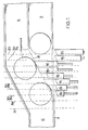
- the deflection device shown in Fig. 1 has a first transport device 12 and a second transport device 14 which, for. B. can consist of a steel or plastic link chain.
- the transport devices are laterally limited by railings 15, 16 and 17.
- the second transport device runs parallel and immediately adjacent to the first transport device. In a certain area, the so-called deflection section, the railings are interrupted or angled to enable objects to be transferred from the first transport device to the second transport device.
- three objects are shown, of which the mit ⁇ lere separated, i. H. is to be deflected or diverted while the first and third objects are to be conveyed further on the first transport device.
- the middle object is carried on by the second transport device.
- a selected object is deflected by Seg. elements 18n (n stands for a, b, c ).
- the segments are fixed in the conveying device of the transport devices and can be extended approximately perpendicular to this conveying direction.
- the segments are preferably extended approximately in the direction the bisector of the obtuse angle formed by the deflection surface 30 and the first transport device 12.
- the segments can consist of a vertical bracket 20 and several horizontal fingers 22.
- the length of the horizontal fingers 22 is preferably determined by the extension paths of the individual segments, so that the railing 16 interrupted at the deflection section can be replaced by one or more guide rods 23 which guide the objects cleanly when the individual segments are retracted.
- the deflection path is the area delimited by the first and last segment.
- Each segment 18 is connected to the piston 25 of a pneumatic cylinder 26 by a shaft 24. Depending on the position of a solenoid control valve 28, the segment is extended or retracted.
- the attack surfaces of the segments for. B. the front edges of the fingers 22, a deflecting surface 30 through which the selected objects are deflected onto the second transport device.
- the segments can be extended to different extents and the contact surface of the segments is opposite. bevelled towards the conveying direction.
- the segment 18a is extended so far that its contact surface is flush with the railing 16
- the remaining segments 18b to 18h are extended so far that their contact surface is flush with the contact surface of the preceding segment.
- the first segments e.g. 3. 18a to 18c, preferably have a curved engagement surface, so that the railing 16 merges into the deflection surface 30 in a smooth curve.
- the smooth transition of the railing 16 into the deflecting surface 30 enables a bumpless deflection of the selected objects even at high working speeds.
- the length of the segments 18n depends on the dimension of the objects in the conveying direction and the distance of the objects from one another.
- the width of the segments is preferably less than about half or about a third of the distance between the leading edges of successive objects. If the objects follow each other immediately, the width of the individual segments should not be greater than about half the dimension of the objects in the conveying direction.
- the segment width should preferably be smaller than about a third of this dimension.
- the segments do not have to have the same width and the first segments can e.g. B. have a slightly larger width.
- the number of segments depends on the size of the objects and the conveying speed.
- the segments are moved in the plane of the transport devices and perpendicular to the conveying direction. However, it is also possible to retract the segments vertically from above.
- the segments can have individual fingers 22 or the contact surface of the segments can be formed by a closed metal or plastic surface.
- the angle which the deflection surfaces 30 forms with the conveying direction of the first transport device 12 depends on the conveying speed and is smaller the higher the conveying speed.
- An air cushion between the objects and the segments can be formed by fine air nozzles in the surface of the segments. Such an air cushion can reduce the friction between the objects and the contact surfaces of the segments and even accelerate an object to be deflected in the deflection direction. Air cushions of this type also avoid the partial overtaking of a deflected object by a subsequent object, since the deflected object is not braked.
- Fig. 1 only a number of segments are shown, which are located on the lower edge of the first transport device in the figure.
- the inclined railing 15 can also be replaced by a series of segments, the contact surfaces of which run parallel to the conveying direction of the first transport device and which are controlled so that they have a fixed distance which corresponds to the width of the first transport device, own of the segments 18n.
- the further segments can be firmly connected to the segments 18n while maintaining this distance. If a jam occurs in the first transport device downstream of the deflection device, such a row of second segments is particularly advantageous since it prevents the objects from being inadvertently diverted onto the second transport device.
- the extension of the segments represents a pure translational movement.
- the segments are extended based on a rotational movement (FIGS. 5, 6 and 10).
- the segments 58n are individually rotatable on an axis 51 which is vertical, approximately at the height of the first segment 58a, directly adjacent to the first transposing device.
- Each segment is extended by a pneumatic cylinder or by an electromagnet 55 which, in order to take advantage of the leverage, acts close to the axis of rotation.
- the segments themselves consist of preferably two angles 57, each of which has a leg 52 which is bent concentrically to the pivot point. These curved legs of the two angles end at a vertical bracket 56 which has on the opposite side one or more risers (sliding lugs 59), along which the objects can slide.
- Bracket and sliding lugs form an acute angle with the radius vector to the segment tip such that when segments are retracted in the conveying direction there is a smooth plane which then inevitably merges into a smooth deflection plane at any angle to the conveying direction by pivoting out the individual segments.
- an axis of rotation lying horizontally next to the first transport device is also possible as a suspension for the railing segments.
- This axis of rotation can be located both in the plane given by the surface of the transport devices and above or below this plane; the direction of the axis of rotation can be parallel to the conveying direction or to the deflection surface or can also assume an intermediate value;
- those segments are in the extended state which attack the selected object at the relevant time or immediately thereafter.
- those segments that do not collide with the immediately preceding and the immediately following object that remain on the first transport device can be in the extended state at any time. As a result, the maximum number of segments is in the extended state during a deflection process.
- test takes place on the test line 32, which is preferably located directly in front of the deflection path. If the test is carried out earlier, it must be carried out by suitable means, e.g. B. a shift register, time delayed or stored so that the test result of the control device for the segments is supplied at the time when the object in question enters the deflection path.
- suitable means e.g. B. a shift register, time delayed or stored so that the test result of the control device for the segments is supplied at the time when the object in question enters the deflection path.
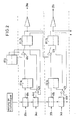
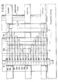
- the device for controlling the segments has the test devices mentioned above, light barriers 34a to 34h for generating a drive-in command, light barriers 35a to 35h for clearing the respective segment and control electronics (FIG. 2).
- the control device shown in FIGS. 1 and 2 the alternative is shown in which the maximum number of segments is extended, ie all segments that do not collide with the immediately preceding and the immediately following object that are not to be deflected .
- the light barrier 35a emits a clear message after the passage of the object that precedes the object to be deflected.
- the free message t delayed by a time element 40a at a time and applied to the set input of flip-flop 1a.
- the amount of the time delay depends on the speed of the first transport device, the response time of the control device and the position of the light barrier 35a.
- the free report is a prerequisite for extending a segment and the time delay should be such that the object from which the free report is derived is no longer hit by the segment that then exits on the basis of the free report.
- the time delay then depends on the speed of the transportation device. Since the transport speed can change during operation, the delay introduced by the timer 40a is preferably variable. With a low transport speed, the time delay is greater than with a high transport speed.
- the signal obtained at the normal output of the flip-flop 1a is fed to the set input of a flip-flop 2a via an AND gate 41a.
- the second input of the AND gate 41a is connected to the normal output of a flip-flop 0, which is set by the test device and g. B. is in the set state if the object that follows the object from which the free notification was to be sorted out, since it z. B. is faulty.
- the normal output of the flip-flop 2a controls a control valve 28 via a power driver. B. actuates a pneumatic cylinder 26 which extends the segment 18a.
- the segment 18a is always extended when an object to be deflected approaches this segment and the immediately preceding object has already moved past this segment.
- the control electronics assigned to the segment 18b is apart from the fact that the second input of the AND gate 41b is not included the flip-flop 0, but is connected to the normal output of the flip-flop 2a, identical to the control electronics assigned to the segment 18a.
- the segment 18b is accordingly extended when there is a free signal from the light barrier assigned to this segment and when the segment 18a is extended.
- the control electronics of the other segments is analogous to that of segment 18b. Any segment is therefore extended if there is a free message for this segment and the preceding segment is extended.
- An entry command is derived from the front edge of each object by further light barriers 34n.
- a light barrier 34n for the entry command is also assigned to each segment 18n.
- the move-in command is delayed via timers 44n.
- the light barrier 34n for the entry command of a segment is located approximately one segment width in front of the light barrier for the free signaling of the relevant segment if timers 40n and 44n are used with the same time delay.
- the output of the timer 44a is connected to one input of an AND gate 42a.
- the other input of the AND gate 42a is connected to the inverted output of the flip-flop 0.
- the flip-flop 1a and the flip-flop 2a are reset by an L output signal from the AND gate 42a.
- the UNC member 42a has a dual function: first, it prevents unnecessary retraction of the segments if two successive objects are to be deflected, and second, it prevents the retract command derived from an object to be deflected, a segment is retracted before this object has moved past this segment.
- the segment 18b is retracted when the relevant entry command light barrier 34b is interrupted by an object and the preceding segment 18a is retracted, ie the flip-flop 2a is reset.
- the segments 18c to 18h are retracted under analog conditions.
- the control device works in such a way that by the last error-free object, for. B. the first five segments 18a to 18e are registered. If the test device then detects a defective object, flip-flop 0 is set and the first five segments are extended practically simultaneously.
- the segments 18f, 18g etc. are only extended when they are also registered, ie the release command light barriers 35f, 35g etc. assigned to them are no longer interrupted by the last fault-free object.
- the light barriers 34a to 34h and 35a to 35h are located on the lines correspondingly designated in FIG. 1.
- the broken lines which are denoted by 34a to 34h and by 35a to 35h, do not represent the actual scanning lines, ie the position of the light barriers, but rather mark the position at which the leading edge or trailing edge of the controlling object is located at the moment of the scanning, ie the generation of the control pulse.
- the actual position of the light barriers must take into account the conveying speed and the response time of the cylinders and valves as well as the extension and retraction times of the segments.
- the light barriers must therefore be arranged a distance in front of the assigned segments, which essentially results from the product of the conveying speed and the sum of the response time and the extension or retraction time.
- a free signaling light barrier (dark-light transition) and an entry command light barrier (light-dark transition) are normally required for each segment. If the extension time of segment n is approximately in the same order of magnitude as the entry time of segment n + 1, then the free-signal light barrier of n and the entry command light barrier of n + 1, as shown in FIG. 1, can be combined into a single light barrier summarize, from whose output signal ' by differentiating the flank corresponding to the light-dark transition becomes the entry pulse and the flank E corresponding to the dark-light transition becomes the vacant signaling pulse.
- the position of the scanning systems must be selected so that. given shape and distance of the objects, the individual objects can be safely distinguished from each other (resolved) and the trigger impulses (free messages, entry commands) can be reproduced with a certain accuracy, which essentially depends on the speed of the objects.
- the direction of the light barriers corresponds approximately to that of the bisector of the obtuse angle formed by the deflection plane and the first transport device.
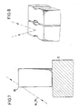
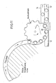
- Objects which do not together form a continuous edge 36 running in the conveying direction can be scanned by means of light barriers (FIG. 7) which run obliquely upwards or downwards (FIG. 7).
- B. cylindrical objects such as cans. Objects that do not form a continuous closed surface together can be scanned from above with suitable reflective light barriers from the discharge side (FIG. 8).
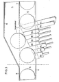
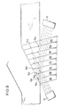
- the principle of control on predecessor and successor enables a particularly favorable light barrier arrangement shown in FIG. 9.
- the light barrier transmitters 93b to 93h and 94a to 94g are integrated in the fingers 22.
- the transmitters can e.g. B. be infrared LEDs, but can also be light guides that lead to fixed light barrier units.
- the beam directions of the light barrier transmitters 93b to 93h that supply the entry commands run from the transmitters in the individual segments preferably parallel to the deflection surface to a first light barrier receiver block 91
- Light barrier receiver block 92 The assignment of the light barriers is selected such that each of the segments 18b to 18h is retracted by an approaching object that cannot be diverted by the signal of its entrance light barrier and each of the segments 18a to 18g the next segment depending on the object to be diverted previous object is released or extended.
- the first segment 18a is controlled by the test light barrier (test line 32).
- the position of transmitter and receiver can also be interchanged so that blocks 91 and 92 are transmitters and the receivers are in the segments.
- the course of the individual objects can also be followed by inductive or capacitive proximity switches, ultrasonic, air barriers etc. or with video (CCD) cameras.
- CCD video
- Such camera systems are not only used for objects that are difficult to resolve, but also for deflection devices that have to process different embodiments of certain objects in alternating operation (e.g. fill level and closure control in beverage filling systems that can be set on several types of bottles).
- the segments are extended at the earliest possible date and are no longer in motion when the object to be deflected hits a segment. This prevents the objects from being knocked over by the moving segments.
- the fact that only a subsequent object gives the command to retract the segments ensures that, on the one hand, an object is diverted through the deflecting surface formed by the segments when the distances between the objects are greater, and on the other hand with certainty when the distances between the objects are small and the sequence is close last segments are retracted so that they do not hinder the transport of the objects.
- Another advantage is that in the case of several objects which are deflected one after the other, regardless of the distances between these objects, the segments are extended only once and the next object which is not to be rejected, since it is e.g. B. is error-free, retracted. If the clearance notification and the entry command were derived from an object itself instead of from the preceding and the following object, the segments for each individual object would be extended and retracted in the aforementioned case.
- the independence of the control from the object to be rejected is also advantageous since the control is independent of the shape and position of an object. If, on the other hand, the control is derived from the object to be deflected itself, the detection of different types of objects by means of light barriers becomes difficult or impossible. For example, by controlling the segments depending on the preceding and following items, it becomes possible to make bottles of a different shape from a series of cylindrical bottles. e.g. B. to sort out square bottles, or overturned bottles and even bottle bottoms and generally broken bottles and broken glass. This is not possible with known sorting devices.
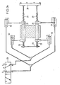
- the piston rod of each double-acting cylinder 26 of the segments carries a helical compression spring on each cylinder side.
- the spring travel is short in relation to the stroke length of the piston, e.g. B. half as long, and their forces are dimensioned and counter-bearings arranged at such intervals in front of the piston that the springs are compressed in the end positions between about 2 and 15 mm (depending on the stroke length) until the forces are balanced. 13, the yoke 64 and the bracket 20 form the counter bearings.
- the end position of the piston is therefore the position in which the spring force is equal to the piston force generated by the pressure force.
- the springs can also be arranged within the cylinder or can be designed as leaf springs.
- springs with a constant spring rate Normally you can use springs with a constant spring rate. However, if the proportion of kinetic energy is very high or only minimal overshoot is required in the end position, springs with an exponential or progressive characteristic curve or several concentrically arranged springs with different spring rates must be used.
- one port 61 is now pressurized with compressed air, i. H. the railing segment is extended (Fig. 13) and the left spring is compressed. Now switches the control electronics to the control valve 28 so that after the delay due to the switching time of the control valve 28 the other port 62 is pressurized with compressed air and the one port 61 is relieved, then the piston rod will move immediately to the left, since the force of the tensioned Spring 29, which is equal to the piston force, is sufficient in itself to overcome the static friction of the piston and to expel the air in the opposite cylinder chamber via the quick exhaust valve 63 and the control valve 28.
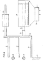
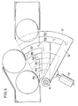
- the deflection device according to the invention can also be used in connection with the outlet star of a filling device, a labeling machine, etc. 11, the deflection devices are arranged so that the bottles can leave the spout when the deflection devices are retracted or switched off on the transport device 12, while the bottles with the deflection devices extended or switched on from the spout starter to a second transport device 14, a turntable, etc. . get picked up.
- FIG. 12 shows another possible combination of the deflection device according to the invention with a transport star.
- This arrangement is particularly advantageous under dynamic pressure.
- the main stream of objects is rotated in the direction by 90 ° by the deflecting surface 30 and sluiced onto a transport device.
- the objects to be deflected determined by an inspector, on the other hand, continue straight ahead.
- the control method described above is reversed. By changing the direction of the main flow of objects it is achieved that, for. B. the back pressure occurring in a production line remains without influence on the device and can be sorted out under full back pressure in the production line.
- a further possible application of the device is obtained if the friction between the object and the segment is increased by a friction lining which is applied to the contact surfaces of the segments. This allows the objects to be moved to another position when deflected. (Cylindrical objects, for example, roll off the deflection plane - cuboid-shaped ones make one or more quarter-turns about their axis if the flow switch is controlled accordingly.)
- a beverage filling system is described below, which is set up to fill different cylindrical bottle types (diameter 50-90 mm) in alternating operation; where the filled bottles are checked for closure and level and then a good-bad sort tion is executed. .
- the deflection section runs parallel to the first transport device 12 in the form of a steel link chain; on which the production line runs, a second transport device 14 at a distance of about. 5 to 10 mm, which is used to remove the deflected bottles.
- the fixed side railing 15 of the first transport device. 12 turns parallel to the deflection plane in the deflection section and becomes the outer railing 15 of the second transport device 14.
- the second railing 16 of the first transport device 12 consists of two superimposed ones.
- Guide rods 23 which can be displaced inwards and outwards perpendicular to the conveying direction in order to adapt to different bottle diameters.
- the two transport devices have a common fixed railing 17 immediately after the deflection section, by means of which mixing after the deflection is avoided
- the deflection device itself consists of 9 individually extendable segments 18, which are closely lined up. These segments each consist of 3 fingers 22, which are attached to a vertical bracket 20 in such a way that one just over the steel link chain, one between and. one can be extended over the two guide rods 23.
- the length of the fingers 22 is determined by the extension path; for example, in this embodiment the shortest finger (segment 18a) is approximately 30 mm and the longest finger (segment 18i) is approximately 115 mm long.
- the fingers 22 are chamfered on their front side in such a way that they form a smooth deflection plane in the extended state, which is approximately at an angle of 30 ° to the conveying direction.
- the first segment 18a has a slight curvature so that the. Bottles are guided in a smooth transition from the conveying direction to the deflection direction.
- the first segment 18a with a width of approximately 28 mm is somewhat wider than the remaining 8 segments, all of which have a width of 20 mm.
- the extension direction forms an angle of 105 ° with the conveyor.
- a guide rod 27 is fastened on the side opposite the fingers at the upper end, which is guided in plastic bushings 27a and thus gives the segment the necessary stabilization.
- the piston rod of the pneumatic cylinder 26 used as an actuator engages approximately in the middle of the bracket.
- the cylinder 26 is controlled by an electrically actuated 5/2-way valve as a control valve 28.
- All segments and actuators are mounted on a base plate that can be moved together with the railing guide rods.
- the control principle described above applies to the predecessor and successor of the object to be rejected.
- the test line about 15 cm in front of the first segment is represented in this version by a trigger light barrier, which FF 0 sets or does not set depending on the two test conditions level / closure.
- a 256 ⁇ 1 element CCD camera is used to determine the position of the predecessor and the successor of a bottle to be rejected.
- the version described here is suitable for cylindrical bottles with a diameter of 56 mm and has an output of up to 50,000 bottles per hour (belt speed approx. 1.5 m / sec).
- the structure of the transport device is the same as that in Example 1, except that the railing 16 is interrupted in the deflection section.
- the deflection device in turn consists of 9 individually extendable segments which are lined up closely together.
- the segments each consist of a vertical, 100 mm high and about 20 mm wide (the first segment has a width of 25 rnm) plastic hill with 4 ridges (sliding tabs), along which the bottles slide.
- the segments are extended and retracted by double-acting cylinders (16 mm piston diameter) with a continuous piston rod; these cylinders are controlled via electrically operated 5/2 way valves with quick exhaust.
- the piston rods each carry two 30 mm long springs.
- a guide rod is attached to the segments above the cylinders and is connected to the piston rod on the other side by a yoke.
- the cylinders sit in a carrier block made of plastic, which is also a slide bearing for the guide rods.
- control principle described above is applied to the predecessor and successor of the object to be rejected, implemented in a microprocessor program.
- a test line 32 (trigger light barrier) about 15 cm in front of the first deflection device determines whether the two test conditions fill level and closure are met or not.
- the air nozzle control device working with a microprocessor "remembers" the defective bottle, ie. H. the position on the transport device (link chain) where it is located.
- This multiple inductive sensor (Fig. 15) consists of 6 individual inductive proximity switches, which are mounted close to the link chain with 44.3 mm center distances.
- the hinges of the link chain which slide over the initiators at 38.1 mm centers, then generate the desired clock pulses.
- the control "knows" exactly when the defective bottle is in front of segment a, b, c, etc.
- the transport speed is calculated from the clock pulses of the inductive scanner and the valves in question are activated earlier (fast) or later (slowly) depending on the transport speed.
- the microprocessor control system follows the course of the bottles that cannot be rejected or their position on the link chain.
- the control unit can always extend the maximum possible number of railing segments between two error-free bottles in the event of an error message from the test facility.
- the control must also take into account the operating times of the individual segments, since the transport speed varies constantly (0 to 1.5m / sec.).
- the microprocessor In accordance with the respective transport speed, which is automatically calculated from the time interval between the clock pulses, the microprocessor repeatedly calculates the necessary advance of its control points (retraction-extension) for each individual cylinder and takes them into account in the control.
Landscapes
- Engineering & Computer Science (AREA)
- Mechanical Engineering (AREA)
- Branching, Merging, And Special Transfer Between Conveyors (AREA)
- Control Of Conveyors (AREA)
- Special Conveying (AREA)
- Sorting Of Articles (AREA)
- Discharge Of Articles From Conveyors (AREA)
- Attitude Control For Articles On Conveyors (AREA)
Claims (8)
Priority Applications (1)
| Application Number | Priority Date | Filing Date | Title |
|---|---|---|---|
| DE8080107500T DE2967439D1 (en) | 1978-01-13 | 1979-01-05 | Device for the lateral deviation of articles from a first conveying device to a second one |
Applications Claiming Priority (2)
| Application Number | Priority Date | Filing Date | Title |
|---|---|---|---|
| DE2801387 | 1978-01-13 | ||
| DE19782801387 DE2801387A1 (de) | 1978-01-13 | 1978-01-13 | Sortiergeraet |
Related Child Applications (1)
| Application Number | Title | Priority Date | Filing Date |
|---|---|---|---|
| EP80107500.3 Division-Into | 1980-12-01 |
Publications (2)
| Publication Number | Publication Date |
|---|---|
| EP0003111A1 EP0003111A1 (fr) | 1979-07-25 |
| EP0003111B1 true EP0003111B1 (fr) | 1982-06-02 |
Family
ID=6029459
Family Applications (2)
| Application Number | Title | Priority Date | Filing Date |
|---|---|---|---|
| EP80107500A Expired EP0029614B1 (fr) | 1978-01-13 | 1979-01-05 | Dispositif pour la déviation latérale d'objets d'un premièr sur un second dispositif de transport |
| EP79100027A Expired EP0003111B1 (fr) | 1978-01-13 | 1979-01-05 | Dispositif pour la déviation latérale d'objets sélectionnés d'une première bande transporteuse sur un second dispositif de transport |
Family Applications Before (1)
| Application Number | Title | Priority Date | Filing Date |
|---|---|---|---|
| EP80107500A Expired EP0029614B1 (fr) | 1978-01-13 | 1979-01-05 | Dispositif pour la déviation latérale d'objets d'un premièr sur un second dispositif de transport |
Country Status (8)
| Country | Link |
|---|---|
| US (1) | US4369873A (fr) |
| EP (2) | EP0029614B1 (fr) |
| JP (2) | JPS54108362A (fr) |
| AT (1) | AT372356B (fr) |
| CA (1) | CA1120433A (fr) |
| DE (3) | DE2801387A1 (fr) |
| DK (1) | DK146793C (fr) |
| ES (1) | ES476817A1 (fr) |
Cited By (3)
| Publication number | Priority date | Publication date | Assignee | Title |
|---|---|---|---|---|
| EP2402269A1 (fr) | 2010-06-30 | 2012-01-04 | Krones AG | Dispositif d'évacuation |
| DE102013220682A1 (de) * | 2013-10-14 | 2015-04-16 | Krones Ag | Ausleitvorrichtung zum Ausleiten von Behältern |
| DE102015014275A1 (de) | 2015-11-06 | 2017-05-11 | Heuft Systemtechnik Gmbh | Vorrichtung und Verfahren zum Ausleiten von Objekten mit nicht-rotationssymmetrischer Standfläche |
Families Citing this family (68)
| Publication number | Priority date | Publication date | Assignee | Title |
|---|---|---|---|---|
| DE2801387A1 (de) * | 1978-01-13 | 1979-07-19 | Bernhard Heuft | Sortiergeraet |
| DE2917286A1 (de) * | 1979-04-27 | 1980-11-06 | Bernhard Heuft | Vorrichtung zum seitlichen ablenken von stueckgut von einer ersten bewegungsbahn auf eine zweite bewegungsbahn |
| US4386708A (en) * | 1981-02-12 | 1983-06-07 | American Can Company | Container reject system |
| DE3110883C2 (de) * | 1981-03-20 | 1983-12-22 | Conto control Braschos KG, 5900 Siegen | Vorrichtung zum Aussortieren von fehlerhaften Verpackungseinheiten |
| DE3130052C2 (de) * | 1981-07-30 | 1986-03-06 | Alcoa Deutschland Gmbh Maschinenbau, 6806 Viernheim | Einrichtung zum Aussortieren fehlerhafter Behälter |
| US4501365A (en) * | 1981-10-26 | 1985-02-26 | Industrial Automation Corp. | Transfer system |
| JPS59105881A (ja) * | 1982-12-03 | 1984-06-19 | インダストリアル・オ−トメイシヨン・コ−ポレイシヨン | 選択的運搬装置 |
| DE3307757A1 (de) * | 1983-03-04 | 1984-09-06 | Bernhard 5475 Burgbrohl Heuft | Vorrichtung zum verteilen von gegenstaenden auf zwei oder mehrere abfuhrfoerderer |
| JPS6355037A (ja) * | 1986-08-22 | 1988-03-09 | 株式会社 東亜製作所 | 瓶等容器の排出装置 |
| DE3711605A1 (de) * | 1987-04-07 | 1988-10-27 | Bernhard Heuft | Vorrichtung zum steuern des transportweges von gegenstaenden |
| JPH0620937B2 (ja) * | 1987-10-26 | 1994-03-23 | 東洋ガラス株式会社 | 容器の整列装置 |
| AU616588B2 (en) * | 1989-01-12 | 1991-10-31 | Dexion (Australia) Pty Limited | Diverter mechanism |
| EP0402703B1 (fr) * | 1989-06-10 | 1995-02-15 | W. SCHLAFHORST AG & CO. | Machine textile avec un système de transport automatique pour transporter des bobines ou des tubes textiles |
| US5042636A (en) * | 1990-03-26 | 1991-08-27 | Robert Underwood | Apparatus and method for displacing conveyed articles |
| FI903419A (fi) * | 1990-07-06 | 1992-01-07 | Halton Oy | Foerfarande och anordning vid sortering av returfoerpackningar av returflaskor, burkar m.m. |
| DE4116969A1 (de) * | 1991-05-24 | 1992-11-26 | Will E C H Gmbh & Co | Vorrichtung zum foerdern von papierbogenstapeln |
| DE4129612C2 (de) * | 1991-09-06 | 1995-10-05 | Ems Elektronik Mestechnik Dipl | Auswerfvorrichtung zum gesteuerten Aussondern flacher Gegenstände, die gefächert über ein Transportband geführt werden |
| US5388682A (en) * | 1994-02-23 | 1995-02-14 | Peco Controls Corporation | Diverter for diverting articles transported along a conveyor belt |
| DE4415561A1 (de) * | 1994-05-03 | 1995-11-09 | Piepenbrock Verpackungstech | Zuführ- und Verteilsystem für Gegenstände |
| US5465828A (en) * | 1994-07-20 | 1995-11-14 | Thomas Air Systems, Inc. | Automated mail processing cleaning system |
| IT1280460B1 (it) * | 1995-09-08 | 1998-01-20 | Cavanna Spa | Dispositivo per suddividere file di articoli in movimento, ad esempio per impianti automatici di confezionamento. |
| DE29518636U1 (de) * | 1995-11-24 | 1997-03-20 | Heuft Systemtechnik Gmbh | Vorrichtung zum Ausleiten von einzelnen rotationssymmetrischen Behältern aus einem unter Staudruck geförderten Strom der rotationssymmetrischen Behälter und Zylinder mit gesteuert ausfahrbarem Kolben |
| US6131720A (en) * | 1996-11-25 | 2000-10-17 | Heuft Systemtechnik Gmbh | Device for separating individual or a plurality of rotationally symmetric containers under backup pressure |
| US5868239A (en) | 1997-01-27 | 1999-02-09 | United Parcel Service Of America, Inc. | Conveyor including controlled package ejection capabilities |
| EP0873950A1 (fr) * | 1997-04-17 | 1998-10-28 | Max Kettner GmbH & Co. KG | Procédé de déviation pour bouteilles d'une voie de transport et dispositif pour la mise en oeuvre du procédé |
| US5971132A (en) * | 1997-06-18 | 1999-10-26 | United Parcel Service Of America, Inc. | High speed automated cog sorter |
| US5897677A (en) * | 1997-07-24 | 1999-04-27 | Owens-Brockway Glass Contianer Inc. | Sampling of hot glassware in a glassware manufacturing system |
| DE29716459U1 (de) | 1997-09-12 | 1999-01-21 | Heuft Systemtechnik Gmbh | Vorrichtung zum Ausleiten von Gegenständen, die auf einem Transporteur befördert werden |
| DE19750726A1 (de) * | 1997-11-15 | 1999-05-20 | Schlafhorst & Co W | Verfahren zum Betreiben einer Kreuzspulen herstellenden Textilmaschine sowie Vorrichtung für eine solche Textilmaschine |
| US6145650A (en) * | 1999-01-29 | 2000-11-14 | Graham Packaging Company L.P. | Apparatus and method for transferring blow-molded containers to a trimmer |
| FR2800361B1 (fr) * | 1999-10-29 | 2001-12-07 | Serac Group | Installation de transfert de recipients comportant un organe de deviation |
| US6419074B1 (en) | 2000-02-10 | 2002-07-16 | Lockheed Martin Corporation | 180 Degree tray rotator |
| ITBO20030523A1 (it) * | 2003-09-11 | 2005-03-12 | Azionaria Costruzioni Acma Spa | Dispositivo deviatore di articoli in avanzamento lungo un percorso di alimentazione predefinito |
| US6910568B1 (en) * | 2004-02-04 | 2005-06-28 | Sandvik Ab | Methods and apparatus for diverting articles from a conveyor |
| ITBO20040119A1 (it) * | 2004-02-27 | 2004-05-27 | Gd Spa | Magazzino fifo a capacita' variabile con stazione di espulsione |
| US7637366B2 (en) * | 2004-06-04 | 2009-12-29 | Shuttleworth, Inc. | High speed diverter |
| US7080962B1 (en) * | 2005-05-31 | 2006-07-25 | Kimberly-Clark Worldwide, Inc. | Air conveyance apparatus |
| FR2895383B1 (fr) * | 2005-12-27 | 2010-03-12 | Sidel Sa | Convoyeur ou transporteur a air |
| US7886891B2 (en) | 2006-02-17 | 2011-02-15 | Sidel Participations | Deflector assembly, valve arrangement for a deflector assembly and method for calibrating same |
| FR2899883B1 (fr) * | 2006-04-18 | 2008-07-04 | Sidel Sas | Aiguillage pourvu de caissons fixes modulaires |
| US7581632B2 (en) * | 2006-06-09 | 2009-09-01 | Tgw-Ermanco Inc. | Sequential diverter for narrow belt conveyor and associated methods |
| CA2655475C (fr) * | 2006-06-13 | 2015-10-27 | Arrowhead Conveyor Corporation, Inc. | Appareil de transport |
| US7997405B2 (en) | 2009-07-22 | 2011-08-16 | Arrowhead Systems, Inc. | Sanitary conveyor |
| US20100084246A1 (en) * | 2008-10-06 | 2010-04-08 | Pitney Bowes Inc. | Item transport system with air divert module |
| IE20090111A1 (en) | 2009-02-11 | 2010-09-01 | Oseney Ltd | Combination air/mechanical rejection |
| DE102009016182B3 (de) * | 2009-04-03 | 2010-04-08 | Uhlmann Pac-Systeme Gmbh & Co Kg | Transportanlage für flache Gegenstände |
| DE102009003847A1 (de) | 2009-04-29 | 2010-11-04 | Krones Ag | Vorrichtung und Verfahren zum Ausleiten von Objekten von einer sich bewegenden Transporteinrichtung |
| US8677929B2 (en) * | 2010-12-29 | 2014-03-25 | Intevac, Inc. | Method and apparatus for masking solar cell substrates for deposition |
| DE102011007935A1 (de) * | 2011-01-03 | 2012-07-05 | Krones Aktiengesellschaft | Anordnung mehrerer miteinander gekoppelter Behälterhandhabungs- und/oder Behälterbehandlungsmodule und Verfahren zum Transport, zur Behandlung und/oder Handhabung von Behältern |
| EP2471728B1 (fr) * | 2011-01-03 | 2019-06-12 | Krones AG | Agencement de plusieurs modules de manipulation et/ou de traitement et/ou de transport de récipients couplés ainsi que procédé de transport, de traitement et/ou de manipulation de récipients |
| ITTO20120590A1 (it) * | 2012-07-04 | 2014-01-05 | Sidel Spa Con Socio Unico | Dispositivo e metodo per il trasporto di entita' discrete |
| US9272850B2 (en) | 2014-03-26 | 2016-03-01 | The Procter & Gamble Company | Diversion apparatus |
| JP6625560B2 (ja) * | 2014-05-08 | 2019-12-25 | レイトラム,エル.エル.シー. | コンベヤ用非接触型ガイド装置 |
| CN105775606B (zh) * | 2016-05-18 | 2018-03-13 | 芜湖百特输送机械有限公司 | 自动提升机 |
| DE102016110016A1 (de) | 2016-05-31 | 2017-11-30 | Khs Gmbh | Herstellungslinie sowie Verfahren zum Betreiben einer solchen Herstellungslinie |
| DE102016122632A1 (de) * | 2016-11-23 | 2018-05-24 | Bizerba SE & Co. KG | Vorrichtung zum Aussondern eines Artikels |
| CN109277312B (zh) * | 2017-07-22 | 2024-02-27 | 上海宇田机电设备有限公司 | 一种理坯、瓶坯口照相检测一体机构 |
| DE102017008044A1 (de) * | 2017-08-25 | 2019-02-28 | Heuft Systemtechnik Gmbh | Ausleitvorrichtung mit Coanda-Stabilisierungseinrichtung |
| DE102017215927A1 (de) * | 2017-09-08 | 2019-03-14 | Krones Aktiengesellschaft | Vorrichtung zum Ausschleusen von in einer Direktdruckmaschine fehlerhaft bedruckten Behältern |
| US11208274B2 (en) | 2018-04-13 | 2021-12-28 | Laitram, L.L.C. | Electromagnetic conveyor system |
| US10457497B1 (en) | 2018-04-13 | 2019-10-29 | Laitram, L.L.C. | Electromagnetic conveyor system |
| DE102018009974B3 (de) | 2018-12-21 | 2020-04-23 | Hansueli Christen | Querfördersorter mit Abräumvorrichtung und Verfahren zum Entfernen von auf einem Querfördersorter deplatziertem Stückgut |
| FR3098131B1 (fr) * | 2019-07-03 | 2022-10-21 | Wid Group | Dispositif de tri d’un conteneur, installation et procédé associés |
| CN110508497A (zh) * | 2019-08-20 | 2019-11-29 | 刘季椿 | 一种轴承钢珠质量检测设备 |
| CN111003478A (zh) * | 2020-01-10 | 2020-04-14 | 张春达 | 一种食品加工用检测线自动分流装置 |
| US11318476B2 (en) | 2020-04-30 | 2022-05-03 | Mss, Inc. | Separation of ferrous materials |
| US11465158B2 (en) | 2020-04-30 | 2022-10-11 | Mss, Inc. | Separation of ferrous materials |
| CN115090568B (zh) * | 2022-07-13 | 2023-10-10 | 余姚市圆成钢球有限公司 | 一种钢球涡流探伤仪自动筛分机构 |
Family Cites Families (22)
| Publication number | Priority date | Publication date | Assignee | Title |
|---|---|---|---|---|
| US2036421A (en) * | 1932-11-12 | 1936-04-07 | Edward B Luckie | Method and apparatus for inserting bottles in boxes |
| US2697513A (en) * | 1952-06-09 | 1954-12-21 | Gerber Prod | Magnetic switching device |
| US2974775A (en) * | 1957-10-30 | 1961-03-14 | American Can Co | Can runway |
| US3270881A (en) * | 1964-01-27 | 1966-09-06 | Electro Dynamics | Material handling system |
| US3351198A (en) * | 1965-02-25 | 1967-11-07 | Owens Illinois Inc | Glass container sorting |
| US3361247A (en) * | 1966-03-28 | 1968-01-02 | Taylor & Gaskin | Article sorting system and method |
| FR1519851A (fr) * | 1967-02-23 | 1968-04-05 | Automatisme Cie Gle | Dispositif de tri automatique |
| US3512638A (en) * | 1968-07-05 | 1970-05-19 | Gen Electric | High speed conveyor sorting device |
| DE6601375U (fr) * | 1968-12-04 | 1969-04-30 | Heller & Co | |
| FR2031366A1 (fr) * | 1969-02-12 | 1970-11-20 | O C C R Organisation Et Contro | Perfectionnements aux transporteurs sur coussin d'air |
| US3580391A (en) * | 1969-10-24 | 1971-05-25 | Gen Electric | Solid-state pulsed electronic control for high-speed conveyor sorting device |
| FR2087171A5 (fr) * | 1970-05-08 | 1971-12-31 | Saunier Duval | |
| FR2187643A1 (fr) * | 1972-06-15 | 1974-01-18 | Seita | |
| ZA74470B (en) * | 1973-01-24 | 1974-11-27 | Petty Ray Geophysical Inc | Can sorter |
| US3791518A (en) * | 1973-04-27 | 1974-02-12 | Metramatic Corp | Side transfer sorting conveyor |
| DE2323028A1 (de) * | 1973-05-08 | 1974-11-14 | Motch Merryweather Machinery | Luftfoerderer fuer flache, duenne gegenstaende |
| DE2437798C2 (de) * | 1974-08-06 | 1984-12-06 | Paolo Lugano-Paradiso Müller | Vorrichtung zur Prüfung von Flaschen bezüglich ihres Füllstandes |
| JPS5235833U (fr) * | 1975-09-05 | 1977-03-14 | ||
| US3982619A (en) * | 1975-10-01 | 1976-09-28 | American Can Company | Flow control apparatus and method |
| DE2555192C3 (de) * | 1975-12-09 | 1978-11-16 | Werner 4100 Duisburg Seidler | Sortiervorrichtung zum kontinuierlichen Ausschleusen von Gegenständen, insbesondere Warenpackungen |
| DE2557887C3 (de) * | 1975-12-22 | 1978-10-26 | Conto Kontrollanlagen Braschos + Achenbach Kg, 5900 Siegen | Sortiervorrichtung zum Aussortieren von fehlerhaften zylindrischen oder teilweise zylindrischen Körpern, insbesondere Flaschen o.dgl |
| DE2801387A1 (de) * | 1978-01-13 | 1979-07-19 | Bernhard Heuft | Sortiergeraet |
-
1978
- 1978-01-13 DE DE19782801387 patent/DE2801387A1/de not_active Ceased
- 1978-12-22 AT AT0925078A patent/AT372356B/de not_active IP Right Cessation
-
1979
- 1979-01-05 EP EP80107500A patent/EP0029614B1/fr not_active Expired
- 1979-01-05 DE DE8080107500T patent/DE2967439D1/de not_active Expired
- 1979-01-05 EP EP79100027A patent/EP0003111B1/fr not_active Expired
- 1979-01-05 DE DE7979100027T patent/DE2962977D1/de not_active Expired
- 1979-01-10 US US06/002,261 patent/US4369873A/en not_active Expired - Lifetime
- 1979-01-12 DK DK13479A patent/DK146793C/da not_active IP Right Cessation
- 1979-01-12 CA CA000319562A patent/CA1120433A/fr not_active Expired
- 1979-01-12 JP JP139279A patent/JPS54108362A/ja active Granted
- 1979-01-12 ES ES476817A patent/ES476817A1/es not_active Expired
-
1986
- 1986-09-11 JP JP61212874A patent/JPS62171819A/ja active Granted
Cited By (6)
| Publication number | Priority date | Publication date | Assignee | Title |
|---|---|---|---|---|
| EP2402269A1 (fr) | 2010-06-30 | 2012-01-04 | Krones AG | Dispositif d'évacuation |
| DE102010025744A1 (de) | 2010-06-30 | 2012-01-05 | Krones Aktiengesellschaft | Ausleitvorrichtung |
| DE102013220682A1 (de) * | 2013-10-14 | 2015-04-16 | Krones Ag | Ausleitvorrichtung zum Ausleiten von Behältern |
| US9550632B2 (en) | 2013-10-14 | 2017-01-24 | Krones Ag | Diverting device for diverting containers |
| DE102015014275A1 (de) | 2015-11-06 | 2017-05-11 | Heuft Systemtechnik Gmbh | Vorrichtung und Verfahren zum Ausleiten von Objekten mit nicht-rotationssymmetrischer Standfläche |
| US10507981B2 (en) | 2015-11-06 | 2019-12-17 | Heuft Systemtechnik Gmbh | Device and method for discharging objects with a non-rotationally symmetrical base surface |
Also Published As
| Publication number | Publication date |
|---|---|
| DK146793B (da) | 1984-01-09 |
| EP0003111A1 (fr) | 1979-07-25 |
| US4369873A (en) | 1983-01-25 |
| JPS54108362A (en) | 1979-08-24 |
| ATA925078A (de) | 1983-02-15 |
| JPH0541525B2 (fr) | 1993-06-23 |
| DE2967439D1 (en) | 1985-05-23 |
| JPS62171819A (ja) | 1987-07-28 |
| DE2962977D1 (en) | 1982-07-22 |
| AT372356B (de) | 1983-09-26 |
| DK13479A (da) | 1979-07-14 |
| EP0029614B1 (fr) | 1985-04-17 |
| EP0029614A1 (fr) | 1981-06-03 |
| CA1120433A (fr) | 1982-03-23 |
| DE2801387A1 (de) | 1979-07-19 |
| JPH0217444B2 (fr) | 1990-04-20 |
| DK146793C (da) | 1984-06-25 |
| ES476817A1 (es) | 1979-11-01 |
Similar Documents
| Publication | Publication Date | Title |
|---|---|---|
| EP0003111B1 (fr) | Dispositif pour la déviation latérale d'objets sélectionnés d'une première bande transporteuse sur un second dispositif de transport | |
| EP2807097B1 (fr) | Appareil et procédé pour dévier des articles, en particulier des récipients tels que des bouteilles | |
| EP0019117B1 (fr) | Dispositif pour la deflection latérale de marchandises d'une première vers une seconde voie de transport | |
| EP0804365B1 (fr) | Procede et dispositif pour faire tourner des contenants a symetrie de rotation, tels que des bouteilles, pendant leur transport effectue sous pression dynamique | |
| DE2541813C2 (de) | Einrichtung zum Ordnen einer Anzahl ungeordnet herangeführter Behälter zu einer einzigen sich fortbewegenden Reihe | |
| DE3221324C2 (fr) | ||
| EP2520521A1 (fr) | Procédé et dispositif destinés à dévier et orienter des marchandises ou articles | |
| EP0286080A1 (fr) | Dispositif pour diriger le transfert d'objets | |
| EP3057891B1 (fr) | Dispositif d'écartement pour écarter des récipients | |
| DE10143430C1 (de) | Vorrichtung und Verfahren zum Sortieren von Gegenständen | |
| EP1012087B1 (fr) | Dispositif et procede pour mettre a l'ecart des objets transportes sur un transporteur | |
| DE3442576A1 (de) | Foerder- und sortiervorrichtung | |
| EP0071068B1 (fr) | Dispositif de triage de récipients | |
| EP1424296A1 (fr) | Système de transport d'articles, en particulier conteneurs pour bagages, et procédé de commande pour le système de transport | |
| DE102016201282A1 (de) | Verfahren zum portionierten Abpacken von flachen Produkten | |
| DE3130308C2 (de) | Vorrichtung zum Ausleiten von fehlerhaften Produkten aus einem Förderband | |
| DE3346129A1 (de) | Verfahren und vorrichtung zum sortieren von altglas enthaltendem abfall | |
| DE3714108A1 (de) | Vorrichtung zur uebergabe von werkstuecktraegern | |
| WO1997019873A1 (fr) | Dispositif pour selectionner un ou plusieurs contenants a symetrie de rotation dans un flux de tels contenants transportes sous l'effet d'une pression dynamique et verin avec piston a deplacement commande | |
| DE2627277C2 (de) | Verfahren zum geräuscharmen Zusammenführen von Gefäßen | |
| DE202012007853U1 (de) | Vorrichtung zum Ausleiten von Gegenständen | |
| DE2324703C2 (de) | Vorrichtung zum Aufteilen von Gefäßen | |
| DE10126876A1 (de) | Verfahren und Vorrichtung zum Sortieren von Stückgütern | |
| DE19711231C2 (de) | Verfahren und Vorrichtung zum Transport von Flaschen o. dgl. | |
| DE4330796A1 (de) | Vorrichtung zum Überführen eines breiten Fördergutstromes zu einem abzufördernden einspurigen Fördergutstrom |
Legal Events
| Date | Code | Title | Description |
|---|---|---|---|
| PUAI | Public reference made under article 153(3) epc to a published international application that has entered the european phase |
Free format text: ORIGINAL CODE: 0009012 |
|
| AK | Designated contracting states |
Designated state(s): BE CH DE FR GB IT LU NL SE |
|
| 17P | Request for examination filed | ||
| ITF | It: translation for a ep patent filed |
Owner name: ING. C. GREGORJ S.P.A. |
|
| GRAA | (expected) grant |
Free format text: ORIGINAL CODE: 0009210 |
|
| AK | Designated contracting states |
Designated state(s): BE CH DE FR GB IT LU NL SE |
|
| REF | Corresponds to: |
Ref document number: 2962977 Country of ref document: DE Date of ref document: 19820722 |
|
| ITTA | It: last paid annual fee | ||
| EPTA | Lu: last paid annual fee | ||
| EAL | Se: european patent in force in sweden |
Ref document number: 79100027.6 |
|
| PGFP | Annual fee paid to national office [announced via postgrant information from national office to epo] |
Ref country code: LU Payment date: 19971209 Year of fee payment: 20 |
|
| PGFP | Annual fee paid to national office [announced via postgrant information from national office to epo] |
Ref country code: GB Payment date: 19971229 Year of fee payment: 20 |
|
| PGFP | Annual fee paid to national office [announced via postgrant information from national office to epo] |
Ref country code: CH Payment date: 19980106 Year of fee payment: 20 |
|
| PGFP | Annual fee paid to national office [announced via postgrant information from national office to epo] |
Ref country code: FR Payment date: 19980109 Year of fee payment: 20 |
|
| PGFP | Annual fee paid to national office [announced via postgrant information from national office to epo] |
Ref country code: SE Payment date: 19980119 Year of fee payment: 20 |
|
| PGFP | Annual fee paid to national office [announced via postgrant information from national office to epo] |
Ref country code: NL Payment date: 19980130 Year of fee payment: 20 Ref country code: DE Payment date: 19980130 Year of fee payment: 20 |
|
| PGFP | Annual fee paid to national office [announced via postgrant information from national office to epo] |
Ref country code: BE Payment date: 19980217 Year of fee payment: 20 |
|
| BE20 | Be: patent expired |
Free format text: 19990105 *HEUFT BERNHARD |
|
| PG25 | Lapsed in a contracting state [announced via postgrant information from national office to epo] |
Ref country code: GB Free format text: LAPSE BECAUSE OF EXPIRATION OF PROTECTION Effective date: 19990104 Ref country code: CH Free format text: LAPSE BECAUSE OF EXPIRATION OF PROTECTION Effective date: 19990104 |
|
| PG25 | Lapsed in a contracting state [announced via postgrant information from national office to epo] |
Ref country code: NL Free format text: LAPSE BECAUSE OF EXPIRATION OF PROTECTION Effective date: 19990105 Ref country code: LU Free format text: LAPSE BECAUSE OF EXPIRATION OF PROTECTION Effective date: 19990105 |
|
| PG25 | Lapsed in a contracting state [announced via postgrant information from national office to epo] |
Ref country code: SE Free format text: LAPSE BECAUSE OF NON-PAYMENT OF DUE FEES Effective date: 19990106 |
|
| REG | Reference to a national code |
Ref country code: GB Ref legal event code: PE20 Effective date: 19990104 |
|
| REG | Reference to a national code |
Ref country code: CH Ref legal event code: PL |
|
| NLV7 | Nl: ceased due to reaching the maximum lifetime of a patent |
Effective date: 19990105 |
|
| EUG | Se: european patent has lapsed |
Ref document number: 79100027.6 |
|
| PLBE | No opposition filed within time limit |
Free format text: ORIGINAL CODE: 0009261 |
|
| STAA | Information on the status of an ep patent application or granted ep patent |
Free format text: STATUS: NO OPPOSITION FILED WITHIN TIME LIMIT |