EP0402703B1 - Machine textile avec un système de transport automatique pour transporter des bobines ou des tubes textiles - Google Patents
Machine textile avec un système de transport automatique pour transporter des bobines ou des tubes textiles Download PDFInfo
- Publication number
- EP0402703B1 EP0402703B1 EP90110244A EP90110244A EP0402703B1 EP 0402703 B1 EP0402703 B1 EP 0402703B1 EP 90110244 A EP90110244 A EP 90110244A EP 90110244 A EP90110244 A EP 90110244A EP 0402703 B1 EP0402703 B1 EP 0402703B1
- Authority
- EP
- European Patent Office
- Prior art keywords
- pallets
- textile machine
- machine according
- transport
- electromagnet
- Prior art date
- Legal status (The legal status is an assumption and is not a legal conclusion. Google has not performed a legal analysis and makes no representation as to the accuracy of the status listed.)
- Expired - Lifetime
Links
- 239000004753 textile Substances 0.000 title claims description 21
- 238000005096 rolling process Methods 0.000 claims description 14
- 238000004804 winding Methods 0.000 claims description 13
- 239000002184 metal Substances 0.000 claims description 9
- 229910052751 metal Inorganic materials 0.000 claims description 9
- 238000011144 upstream manufacturing Methods 0.000 claims description 2
- 230000004913 activation Effects 0.000 claims 1
- 230000033764 rhythmic process Effects 0.000 claims 1
- 230000005291 magnetic effect Effects 0.000 description 5
- XEEYBQQBJWHFJM-UHFFFAOYSA-N Iron Chemical group [Fe] XEEYBQQBJWHFJM-UHFFFAOYSA-N 0.000 description 2
- 238000007664 blowing Methods 0.000 description 1
- 230000001427 coherent effect Effects 0.000 description 1
- 239000000428 dust Substances 0.000 description 1
- 230000000694 effects Effects 0.000 description 1
- 239000003302 ferromagnetic material Substances 0.000 description 1
- 239000012811 non-conductive material Substances 0.000 description 1
- 125000006850 spacer group Chemical group 0.000 description 1
- 238000009987 spinning Methods 0.000 description 1
Images


Classifications
-
- B—PERFORMING OPERATIONS; TRANSPORTING
- B65—CONVEYING; PACKING; STORING; HANDLING THIN OR FILAMENTARY MATERIAL
- B65G—TRANSPORT OR STORAGE DEVICES, e.g. CONVEYORS FOR LOADING OR TIPPING, SHOP CONVEYOR SYSTEMS OR PNEUMATIC TUBE CONVEYORS
- B65G21/00—Supporting or protective framework or housings for endless load-carriers or traction elements of belt or chain conveyors
- B65G21/20—Means incorporated in, or attached to, framework or housings for guiding load-carriers, traction elements or loads supported on moving surfaces
- B65G21/2009—Magnetic retaining means
-
- B—PERFORMING OPERATIONS; TRANSPORTING
- B65—CONVEYING; PACKING; STORING; HANDLING THIN OR FILAMENTARY MATERIAL
- B65H—HANDLING THIN OR FILAMENTARY MATERIAL, e.g. SHEETS, WEBS, CABLES
- B65H67/00—Replacing or removing cores, receptacles, or completed packages at paying-out, winding, or depositing stations
- B65H67/06—Supplying cores, receptacles, or packages to, or transporting from, winding or depositing stations
-
- B—PERFORMING OPERATIONS; TRANSPORTING
- B65—CONVEYING; PACKING; STORING; HANDLING THIN OR FILAMENTARY MATERIAL
- B65G—TRANSPORT OR STORAGE DEVICES, e.g. CONVEYORS FOR LOADING OR TIPPING, SHOP CONVEYOR SYSTEMS OR PNEUMATIC TUBE CONVEYORS
- B65G2201/00—Indexing codes relating to handling devices, e.g. conveyors, characterised by the type of product or load being conveyed or handled
- B65G2201/02—Articles
- B65G2201/0235—Containers
- B65G2201/0261—Puck as article support
-
- B—PERFORMING OPERATIONS; TRANSPORTING
- B65—CONVEYING; PACKING; STORING; HANDLING THIN OR FILAMENTARY MATERIAL
- B65H—HANDLING THIN OR FILAMENTARY MATERIAL, e.g. SHEETS, WEBS, CABLES
- B65H2555/00—Actuating means
- B65H2555/10—Actuating means linear
- B65H2555/13—Actuating means linear magnetic, e.g. induction motors
-
- B—PERFORMING OPERATIONS; TRANSPORTING
- B65—CONVEYING; PACKING; STORING; HANDLING THIN OR FILAMENTARY MATERIAL
- B65H—HANDLING THIN OR FILAMENTARY MATERIAL, e.g. SHEETS, WEBS, CABLES
- B65H2701/00—Handled material; Storage means
- B65H2701/30—Handled filamentary material
- B65H2701/31—Textiles threads or artificial strands of filaments
-
- Y—GENERAL TAGGING OF NEW TECHNOLOGICAL DEVELOPMENTS; GENERAL TAGGING OF CROSS-SECTIONAL TECHNOLOGIES SPANNING OVER SEVERAL SECTIONS OF THE IPC; TECHNICAL SUBJECTS COVERED BY FORMER USPC CROSS-REFERENCE ART COLLECTIONS [XRACs] AND DIGESTS
- Y10—TECHNICAL SUBJECTS COVERED BY FORMER USPC
- Y10S—TECHNICAL SUBJECTS COVERED BY FORMER USPC CROSS-REFERENCE ART COLLECTIONS [XRACs] AND DIGESTS
- Y10S209/00—Classifying, separating, and assorting solids
- Y10S209/927—Cop sorter
Definitions
- the invention relates to an automatic textile machine according to the preamble of claim 1.
- JP-OS 52-25 139 discloses a transport system in which the pallets are transported in a closed circuit on conveyor belts and are guided through guide slots.
- a closed transport circuit for pallets within a winding machine is also known, for example, from DE-A-33 26 527.
- the pallets are carried by friction on the conveyor belts on which they rest.
- the pallets are principally guided within a guide slot on their base protruding from the center of the base plate.
- rotating parts are provided within the transport system, for example deflection rollers of the conveyor belts or transport rollers in areas of change in direction, and parts of switches or stoppers engaging in the transport tracks, so that trailing threads can be detected. This can severely impair the functionality of the transport system.
- a device for the lateral deflection of objects, in particular bottles, from a first movement path to a second movement path is known from EP-A-0 029 614, which is alien to the category.
- This document is primarily based on the problem of reliably sorting objects arriving at multiple speeds and multiple transport densities compared to the transport of pallets in a winding machine.
- This problem of high transport speed and high transport density of the objects is overcome by a row of plungers, blowing nozzles or magnets arranged on a branch.
- the use of a series of magnets is limited to objects that themselves have strong magnetic properties.
- the object of the invention is therefore to propose a textile machine in which the pallets, onto which textile bobbins or sleeves are placed, are transported and positioned by means of devices which do not impair the functionality of the transport system.
- the main advantage of the invention results from the fact that elements for stopping, controlling and transporting, which operate according to the invention by means of magnetic forces, do not have any parts which engage directly in the transport path.
- the elements can be controlled very advantageously centrally and are only effective if this is also necessary at this point in time. It is also particularly advantageous that no or only a small number of rotating or clamping parts are present directly on the transport routes.
- the arrangement of two magnets in front of a branch allows the pallets to be stopped, separated and controlled.
- the coil placed on the pallet in its stop position between the two magnets can be checked by a sensor for thread remnants or, for example, the part from which it originates, after which the second magnet, by the duration of its switch-on time, determines the further transport direction the pallet.
- Example for multi-lot processing depending on the lot It is also possible to evenly distribute the cops to preparation devices integrated in the winding machine sections, the stagnation distances of which may be monitored by sensors.
- the pallets 13 are transported along a transport path 58 by means of a frictional connection through a transport belt 58 '.
- the pallets 13 are guided laterally on their base plates by guide edges 56 and 57.
- the guide edges 56 and 57 are designed such that, before reaching a first electromagnet 59, they move the pallets 13 perpendicular to the transport direction of the conveyor belt 58 '.
- a relatively strong change in direction in particular through the design of the leading edge 56, intercepts a more or less strong thrust of the pallets depending on the backflow length, which then only weakens considerably in the area of the stop position between the electromagnet 59 and another one downstream Electromagnet 60 acts.
- the pallets 13 rest only on part of their base area on the conveyor belt 58 ', which also reduces the force component acting in its direction of transport.
- the pallets are fed directly to a guide profile 73 of the electromagnet 59, on which they act under the action of the magnetic force unroll.
- the rolling motion is further supported by the conveyor belt 58 ', on which the pallet 13 only partially rests.
- a proximity sensor 61 detects the arrival or the beginning of the rolling of a pallet 63 on the rolling profile 73 of the electromagnet 59. Its connection to a control unit (not shown) activates the electromagnet 60 with a rolling profile 75. The pallet 13 then assumes a stable position between the two electromagnets 59 and 60, being in contact with both rolling profiles 73 and 75. It is particularly advantageous if a sensor 141 is arranged such that it can scan the cop 14 attached to the pallet 13 or the sleeve 15, preferably photo-optically, during the rest position of the pallet 13. Depending on the arrangement of the branch, the sensor 141 controls the batch of the respective cop 14 or the winding residue still on the sleeve 15.
- This sensor 141 then transmits a signal to the control unit (not shown), which is evaluated in the central control unit according to predetermined criteria and converted into a control signal for the electromagnets 59 and 60. If, for example, the further transport of the pallet 13 along the transport path 58 is provided, both electromagnets 59 and 60 can be switched off. As a result, the pallet 13 is carried along by the conveyor belt 58 'and is guided past the junction of a transponder path 65.
- a further guide edge 66 (not shown here) (see FIG. 2) behind the branch can move the pallet 13 even further in this direction.
- the electromagnet 59 is switched on again in order to stop the subsequent pallet 13.
- the electromagnet 60 is still kept under voltage after the electromagnet 59 has been switched off .
- the pallet 13 rolls on the rolling profile 75 of the electromagnet 60 until it reaches the guide edge 67 belonging to the transport path 65.
- This pallet 13 is then carried along by the conveyor belt 65 ', which is deflected by a deflection roller 65' 'and driven by a motor, not shown, along the conveyor track 65.
- Cover plates 62 and 63 are mainly intended to cover at least a part of the base plates of the pallets 13 in such a way that these pallets 13 cannot tilt, for example due to external influences on the cops 14 or the sleeves 15. From the machine frame, only the frame part 77 can be seen here, to which, among other things, the cover plate 62 is fastened.
- the electromagnets 59 and 60 are fastened to the base frame 72 by means of fastening screws 68 and 74 (see FIG. 5).
- the arrangement of the two electromagnets 59 and 60 enables stopping, singling and controlled branching of pallets at the same time. There are no mechanically moving parts that protrude directly into the transport route.
- the variant of the invention shown in FIG. 2 describes a stop and separating device for pallets 13, which is arranged along a transport path 58.
- the web guide corresponds to that described in the previous embodiment.
- the electromagnet 60 is replaced by a stopper 64 here.
- the respective pallet 13 in the stop position assumes a stable position between the rolling profile 73 of the electromagnet 59 and the stopper 64.
- this pallet 13 leaves this position in that it is carried along by the frictional force of the conveyor belt 58 ′ and rolls off the stopper onto a profile 66, which feeds the pallet 13 back to the normal transport path 58.
- All proximity sensors of the previous exemplary embodiments can be inductively acting sensors, since the pallets 13 in any case consist at least partially of ferromagnetic material. Such sensors are very reliable and not very expensive.
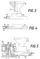
- the electromagnets can carry a coherent cover 35 on their front side as well as the metal rings 34 of the pallets 13 can carry a plastic layer 55 (see FIG. 3). In this way, the generation of metal dust is prevented when the pallets 13 are transported. Since both the thickness of the cover 35 and the thickness of the plastic layer 55 can be kept very small, the effect of the magnetic forces is hardly affected.
- the variant of a pallet 13 ′′ with metal ring 34 ′′ shown in FIG. 5 has the advantage that no jam occurs even with gradations and edges that are possible within a transport system.
- such pallets are suitable to ensure a change of direction from the horizontal or into the horizontal without problems during their transport.
- FIG. 5 further shows, in addition to the pallet 13 ′′, as an example an electromagnet 59 from the previous exemplary embodiment according to FIGS. 5 and 6. It can be clearly seen in this figure that the rolling profile 73 is adapted to the shape of the pallet.
- the electromagnet 59 which is fastened to the base frame 72 by means of a fastening screw 68, has a housing 76. Between this housing 76 and the iron core 70 of the electromagnet, a spacer disk 71 made of non-conductive material is arranged. The coil itself is labeled 69.
- the iron core 70 in which the rolling profile 73 is incorporated, also has a slide plate 63 'for supporting the respective pallet 13' '.
Landscapes
- Engineering & Computer Science (AREA)
- Mechanical Engineering (AREA)
- Replacing, Conveying, And Pick-Finding For Filamentary Materials (AREA)
- Branching, Merging, And Special Transfer Between Conveyors (AREA)
- Non-Mechanical Conveyors (AREA)
- Spinning Or Twisting Of Yarns (AREA)
Claims (15)
- Machine textile comprenant un système automatique de transport pour déplacer des bobines ou des busettes textiles, respectivement, qui sont posées individuellement sur des supports individuels (13 ; 13' ; 13'') le long de voies de transport prédéterminées (58), celles-ci étant pourvues de moyens de guidage (56, 57, 66, 67) qui sont destinés à guider les supports individuels, pour l'essentiel latéralement, caractérisée par le fait que les supports individuels (13 ; 13' ; 13'') sont munis sur leur pourtour d'une bague métallique (34 ; 34' ; 34''), par le fait qu'un électroaimant (28 ; 59, 60 ; 59') est à chaque fois réalisé sous la forme d'une partie à courbure convexe (73, 75) des moyens de guidage, et par le fait qu'il est prévu des moyens pour l'activation asservie de l'électroaimant (28 ; 59, 60 ; 59').
- Machine textile selon la revendication 1, caractérisée par le fait que l'électroaimant (59, 60 ; 59') est disposé sur une voie de transport (58) qui comporte des moyens mécaniques (58) pour transporter les supports individuels (13 ; 13' ; 13'') par conjugaison par frottement.
- Machine textile selon la revendication 1 ou 2, caractérisée par le fait que l'électroaimant (60) est disposé sur une bifurcation de la voie de transport (58).
- Machine textile selon l'une des revendications 1 à 3, caractérisée par le fait que deux électroaimants (59, 60) sont disposés à une distance l'un de l'autre qui est inférieure au diamètre de la plaque de base des supports individuels (13 ; 13' ; 13'').
- Machine textile selon la revendication 4, caractérisée par le fait que l'électroaimant (60) qui est situé en aval sur la voie de transport (58) est disposé d'une manière telle que son profil de roulement (75) constitue en même temps le bord intérieur qui dévie les supports individuels (13 ; 13' ; 13'') vers une voie de bifurcation (65).
- Machine textile selon la revendication 4 ou 5, caractérisée par le fait qu'un détecteur de proximité (61) relié à un circuit qui active l'aimant (60) lors de l'arrivée d'un support individuel (13 ; 13' ; 13'') est disposé entre les aimants (59, 60).
- Machine textile selon la revendication 6, caractérisée par le fait que le détecteur de proximité (61) comporte un circuit qui active à nouveau l'aimant (59) après que l'on a détecté que le support individuel (13 ; 13' ; 13'') a été évacué du fait de la mise hors circuit de cet aimant (59).
- Machine textile selon l'une des revendications 4 à 7, caractérisée par le fait que les aimants (59, 60) présentent une polarité différente dans leur état activé.
- Machine textile selon l'une des revendications 4 à 8, caractérisée par le fait qu'un capteur (141) est disposé sur la voie de transport (58) dans la région où chaque support individuel (13 ; 13' ; 13'') est arrêté dans la position de repos située entre les aimants (59, 60), et qu'il détecte les caractéristiques spécifiques d'une canette (14) ou d'une busette (15), respectivement, qui est transportée par le support individuel, comme un reste d'enroulement ou un lot, et par le fait que ce capteur (141) comporte une liaison opérationnelle avec l'aimant (60) situé en aval, liaison au moyen de laquelle on peut agir sur la durée d'activation de cet aimant (60).
- Machine textile selon la revendication 2, caractérisée par le fait qu'un élément d'arrêt (64) est disposé en aval de l'aimant (59) qui est disposé le long de la voie de transport (58) et qui présente un profil de roulement (73), et ce, à une distance qui est inférieure au diamètre de la plaque de base des supports individuels (13 ; 13' ; 13'').
- Machine textile selon l'une des revendications 1 à 10, caractérisée par le fait que des bords de guidage (56, 57) destinés aux supports individuels (13 ; 13' ; 13'') en amont de l'aimant (59) sont conformés d'une manière telle qu'ils déplacent les supports individuels sur la voie de transport perpendiculairement à la direction de transport et dans la direction de cet aimant.
- Machine textile selon la revendication 11, caractérisée par le fait qu'un autre bord de guidage (66) est disposé en aval, et qu'il déplace les supports individuels (13 ; 13' ; 13'') perpendiculairement à la direction de transport et en les éloignant de l'électroaimant (59, 60 ; 59').
- Machine textile selon la revendication 1, caractérisée par le fait que lesdits moyens sont constitués par un dispositif de commande au moyen duquel l'électroaimant (28 ; 59, 60 ; 59') peut être activé en synchronisme.
- Machine textile selon la revendication 1, caractérisée par le fait que la bague métallique (34'') du support individuel (13'') présente un bord chanfreiné.
- Machine textile selon la revendication 6 ou 7, caractérisée par le fait que les détecteurs de proximité (61; 61') sont des capteurs à effet inductif qui reconnaissent les supports individuels (13 ; 13' ; 13'') par leurs bagues métalliques (34 ; 34' ; 34'').
Applications Claiming Priority (4)
| Application Number | Priority Date | Filing Date | Title |
|---|---|---|---|
| DE3919106 | 1989-06-10 | ||
| DE3919106 | 1989-10-06 | ||
| DE4011797 | 1989-12-04 | ||
| DE4011797A DE4011797C2 (de) | 1989-06-10 | 1990-04-12 | Transportsystem für eine automatische Textilmaschine zum gesteuerten Führen von Paletten entlang vorgegebener Transportwege |
Publications (2)
| Publication Number | Publication Date |
|---|---|
| EP0402703A1 EP0402703A1 (fr) | 1990-12-19 |
| EP0402703B1 true EP0402703B1 (fr) | 1995-02-15 |
Family
ID=25881851
Family Applications (1)
| Application Number | Title | Priority Date | Filing Date |
|---|---|---|---|
| EP90110244A Expired - Lifetime EP0402703B1 (fr) | 1989-06-10 | 1990-05-30 | Machine textile avec un système de transport automatique pour transporter des bobines ou des tubes textiles |
Country Status (3)
| Country | Link |
|---|---|
| US (1) | US5190136A (fr) |
| EP (1) | EP0402703B1 (fr) |
| JP (1) | JP3100607B2 (fr) |
Families Citing this family (30)
| Publication number | Priority date | Publication date | Assignee | Title |
|---|---|---|---|---|
| DE4019099A1 (de) * | 1990-06-15 | 1991-12-19 | Schlafhorst & Co W | Vorrichtung zum positionieren von auf unabhaengige einzeltraeger aufgesetzten spulen und drehen um deren laengsachse |
| DE4019475A1 (de) * | 1990-06-19 | 1992-01-02 | Schlafhorst & Co W | Spulmaschine mit an einer bedienstelle etwa in tischhoehe angeordneten spulenaufnahmemitteln |
| DE4131518A1 (de) * | 1991-09-21 | 1993-03-25 | Schlafhorst & Co W | Transportsystem zum transport von einzeltraegern |
| DE4131608A1 (de) * | 1991-09-23 | 1993-03-25 | Schlafhorst & Co W | Verfahren zum betreiben einer automatischen spulmaschine |
| DE4142790C2 (de) * | 1991-12-23 | 2001-12-13 | Schlafhorst & Co W | Kopstransporteinrichtung in einem Spulautomaten |
| DE4233819C2 (de) * | 1992-10-08 | 2003-05-08 | Schlafhorst & Co W | Verfahren zum Betreiben einer automatischen Spulmaschine bei Partiewechsel |
| DE4312855A1 (de) * | 1993-04-22 | 1994-10-27 | Schlafhorst & Co W | Be- und Entladestation zum Be- und Entladen von Caddy's, auf deren Aufsteckdorne Textilspulen oder Textilspulenhülsen aufgesetzt sind |
| DE4338552C2 (de) * | 1993-11-11 | 2002-08-01 | Schlafhorst & Co W | Kreuzspulen herstellende Textilmaschine mit einer Vielzahl von in Reihe angeordneten Spulstellen |
| DE19518276A1 (de) * | 1995-05-18 | 1996-11-21 | Schlafhorst & Co W | Verfahren zum Betreiben eines Transportsystems einer automatischen Spulmaschine und Transportsystem |
| DE29605595U1 (de) * | 1995-09-20 | 1997-02-13 | Brainpower Consulting Gmbh, Sirnach | Anlage zum Bearbeiten von Gefäßen, Transportvorrichtung zum Transportieren von Gefäßen und Paletten dafür |
| US6227348B1 (en) * | 1996-01-26 | 2001-05-08 | Elpatronic Ag | Method and apparatus for separating and bringing together series of container bodies |
| DE19636661A1 (de) * | 1996-09-10 | 1998-03-12 | Schlafhorst & Co W | Transportsystem für eine Textilmaschine |
| US6047854A (en) * | 1997-02-26 | 2000-04-11 | Sarnoff Corporation | Bead dispersement devices |
| JPH1159901A (ja) * | 1997-08-11 | 1999-03-02 | Murata Mach Ltd | キャリヤー移動装置 |
| DE19816232A1 (de) * | 1998-04-10 | 1999-10-14 | Schlafhorst & Co W | Transportsystem für Spinnspulen und Spulenhülsen mit einem einen Durchgang überbrückenden Transportweg |
| DE19902338B4 (de) | 1999-01-21 | 2004-10-14 | Steag Hamatech Ag | Hubvorrichtung für Substrate |
| JP4855151B2 (ja) * | 2006-06-09 | 2012-01-18 | 三菱電機株式会社 | 軸受装置 |
| DE102007014876B4 (de) * | 2007-03-26 | 2010-04-08 | Kba-Metronic Aktiengesellschaft | Transportsystem |
| CN103540517B (zh) | 2010-07-23 | 2017-05-24 | 贝克曼考尔特公司 | 处理样本的系统及方法 |
| BR112014011043A2 (pt) | 2011-11-07 | 2017-06-13 | Beckman Coulter Inc | detecção de recipiente de espécime |
| KR20140091032A (ko) * | 2011-11-07 | 2014-07-18 | 베크만 컬터, 인코포레이티드 | 검체 수송 시스템의 자기 감쇠 |
| EP2776848B1 (fr) | 2011-11-07 | 2019-12-25 | Beckman Coulter, Inc. | Système et procédé de transport de conteneurs d'échantillons |
| WO2013070740A1 (fr) | 2011-11-07 | 2013-05-16 | Beckman Coulter, Inc. | Système d'aliquote et flux de travail |
| KR20140092375A (ko) | 2011-11-07 | 2014-07-23 | 베크만 컬터, 인코포레이티드 | 원심분리기 시스템 및 작업 흐름 |
| WO2013070754A1 (fr) | 2011-11-07 | 2013-05-16 | Beckman Coulter, Inc. | Bras robotique |
| DE102013218389B4 (de) * | 2013-09-13 | 2023-01-12 | Krones Ag | Vorrichtung und Verfahren zum Schalten einer passiven Weiche für Transportsysteme mit Linearmotoren |
| KR101656784B1 (ko) * | 2014-12-03 | 2016-09-12 | 주식회사 대경 | 책자 |
| ITPO20150002A1 (it) * | 2015-02-06 | 2016-08-06 | Ecafil Best Spa Ind Filati | Sistema e metodo di controllo e programmazione della produzione di un gomitolo |
| JP6697911B2 (ja) * | 2016-03-18 | 2020-05-27 | 日立造船株式会社 | 電子線滅菌設備 |
| US10427162B2 (en) | 2016-12-21 | 2019-10-01 | Quandx Inc. | Systems and methods for molecular diagnostics |
Family Cites Families (12)
| Publication number | Priority date | Publication date | Assignee | Title |
|---|---|---|---|---|
| US2264348A (en) * | 1939-09-16 | 1941-12-02 | American Can Co | Can conveyer |
| US3092237A (en) * | 1961-03-06 | 1963-06-04 | Ways & Means Inc | Conveyor arrangement |
| US3167168A (en) * | 1963-08-15 | 1965-01-26 | Chester P Park | Electromagnetic conveyor |
| US3621979A (en) * | 1968-12-05 | 1971-11-23 | Robert W Kraeft | Magnetic conveyor system |
| FR2136970B1 (fr) * | 1971-05-10 | 1973-05-11 | Webb Co Jervis B | |
| US3941237A (en) * | 1973-12-28 | 1976-03-02 | Carter-Wallace, Inc. | Puck for and method of magnetic conveying |
| DE2801387A1 (de) * | 1978-01-13 | 1979-07-19 | Bernhard Heuft | Sortiergeraet |
| JPS5917464A (ja) * | 1982-07-19 | 1984-01-28 | Murata Mach Ltd | 異種管糸の搬送システム |
| JPS5922862A (ja) * | 1982-07-23 | 1984-02-06 | Murata Mach Ltd | 管糸搬送システム |
| US4681231A (en) * | 1982-12-08 | 1987-07-21 | Murata Kikai Kabushiki Kaisha | Article selecting and conveying system |
| US4605177A (en) * | 1983-09-20 | 1986-08-12 | Murata Kikai Kabushiki Kaisha | Bobbin transporting and treating system |
| US4940127A (en) * | 1986-12-12 | 1990-07-10 | Murata Kikai Kabushiki Kaisha | Wound yarn package transporting system |
-
1990
- 1990-05-30 EP EP90110244A patent/EP0402703B1/fr not_active Expired - Lifetime
- 1990-06-11 JP JP02150102A patent/JP3100607B2/ja not_active Expired - Fee Related
- 1990-06-11 US US07/535,884 patent/US5190136A/en not_active Expired - Fee Related
Also Published As
| Publication number | Publication date |
|---|---|
| JPH03102013A (ja) | 1991-04-26 |
| EP0402703A1 (fr) | 1990-12-19 |
| JP3100607B2 (ja) | 2000-10-16 |
| US5190136A (en) | 1993-03-02 |
Similar Documents
| Publication | Publication Date | Title |
|---|---|---|
| EP0402703B1 (fr) | Machine textile avec un système de transport automatique pour transporter des bobines ou des tubes textiles | |
| DE4011797C2 (de) | Transportsystem für eine automatische Textilmaschine zum gesteuerten Führen von Paletten entlang vorgegebener Transportwege | |
| EP0402630B1 (fr) | Bobinoir automatique avec un système de transport de canettes et de tubes avec plusieurs boucles de transport | |
| EP0286080B1 (fr) | Dispositif pour diriger le transfert d'objets | |
| CH666878A5 (de) | Vorrichtung zum auswaehlen und foerdern von kopsen. | |
| EP0463443B1 (fr) | Dispositif pour positionner de bobines mises sur des supports individuels indépendants et qui provoque la rotation autour leur axe vertical | |
| DE3326537C2 (de) | Rückhalteeinrichtung | |
| EP0406541B1 (fr) | Machine de bobinage automatique à système de transport dans lequel des canettes et tubes sont posés en position verticale sur des palettes | |
| DE3742348A1 (de) | Fadenendesucheinrichtung | |
| DE3407804C2 (fr) | ||
| EP0175150A1 (fr) | Appareil margeur | |
| DE3026075C2 (de) | Spulenwechselvorrichtung an Spinnmaschinen | |
| DE4041715A1 (de) | Transportsystem einer automatischen spulmaschine | |
| DE4430611A1 (de) | Einrichtung zum Erkennen von Fördergut auf Förderbahnen, insbesondere von Stückgut in Rollenförderern | |
| DE4124061C2 (de) | Fördervorrichtung mit zwei hochkant gestellten Flachbandförderern | |
| EP0461569B1 (fr) | Dispositif de transport de supports individuels portant des bobines ou des tubes vides | |
| EP0915051B1 (fr) | Méthode et dispositif pour former un courant d'articles se chevauchant | |
| EP0402731B1 (fr) | Bobinoir automatique avec un transporteur pour cannettes suivant une boucle fermée | |
| DE4142620C2 (de) | Vorrichtung zum Abziehen von auf Transporttellern aufgesteckten Spulenhülsen | |
| DE3622004C2 (fr) | ||
| DE3446461C2 (fr) | ||
| EP0534184B1 (fr) | Système de transport pour transporter des supports individuels | |
| DE4142790C2 (de) | Kopstransporteinrichtung in einem Spulautomaten | |
| DE4224086C2 (de) | Kopsversorgungsaggregat zur Versorgung einer Spulmaschine mit Kopsen unterschiedlicher Garnpartien | |
| DE4037880C2 (de) | Verfahren und Vorrichtung zum Überwachen des Spulenwechselvorganges bei einer Spinnereimaschine |
Legal Events
| Date | Code | Title | Description |
|---|---|---|---|
| PUAI | Public reference made under article 153(3) epc to a published international application that has entered the european phase |
Free format text: ORIGINAL CODE: 0009012 |
|
| AK | Designated contracting states |
Kind code of ref document: A1 Designated state(s): CH DE FR IT LI |
|
| 17P | Request for examination filed |
Effective date: 19910429 |
|
| 17Q | First examination report despatched |
Effective date: 19921104 |
|
| ITF | It: translation for a ep patent filed | ||
| GRAA | (expected) grant |
Free format text: ORIGINAL CODE: 0009210 |
|
| AK | Designated contracting states |
Kind code of ref document: B1 Designated state(s): CH DE FR IT LI |
|
| REF | Corresponds to: |
Ref document number: 59008458 Country of ref document: DE Date of ref document: 19950323 |
|
| ET | Fr: translation filed | ||
| PLBE | No opposition filed within time limit |
Free format text: ORIGINAL CODE: 0009261 |
|
| STAA | Information on the status of an ep patent application or granted ep patent |
Free format text: STATUS: NO OPPOSITION FILED WITHIN TIME LIMIT |
|
| 26N | No opposition filed | ||
| PGFP | Annual fee paid to national office [announced via postgrant information from national office to epo] |
Ref country code: FR Payment date: 19990518 Year of fee payment: 10 |
|
| PG25 | Lapsed in a contracting state [announced via postgrant information from national office to epo] |
Ref country code: FR Free format text: LAPSE BECAUSE OF NON-PAYMENT OF DUE FEES Effective date: 20010131 |
|
| REG | Reference to a national code |
Ref country code: FR Ref legal event code: ST |
|
| PGFP | Annual fee paid to national office [announced via postgrant information from national office to epo] |
Ref country code: CH Payment date: 20040527 Year of fee payment: 15 |
|
| PG25 | Lapsed in a contracting state [announced via postgrant information from national office to epo] |
Ref country code: CH Free format text: LAPSE BECAUSE OF NON-PAYMENT OF DUE FEES Effective date: 20050531 Ref country code: LI Free format text: LAPSE BECAUSE OF NON-PAYMENT OF DUE FEES Effective date: 20050531 |
|
| REG | Reference to a national code |
Ref country code: CH Ref legal event code: PL |
|
| PGFP | Annual fee paid to national office [announced via postgrant information from national office to epo] |
Ref country code: DE Payment date: 20060707 Year of fee payment: 17 |
|
| PGFP | Annual fee paid to national office [announced via postgrant information from national office to epo] |
Ref country code: IT Payment date: 20070531 Year of fee payment: 18 |
|
| PG25 | Lapsed in a contracting state [announced via postgrant information from national office to epo] |
Ref country code: DE Free format text: LAPSE BECAUSE OF NON-PAYMENT OF DUE FEES Effective date: 20071201 |
|
| PG25 | Lapsed in a contracting state [announced via postgrant information from national office to epo] |
Ref country code: IT Free format text: LAPSE BECAUSE OF NON-PAYMENT OF DUE FEES Effective date: 20080530 |