EP0402703B1 - Textile machine with an automatic tranport system to transport textile bobbins or spools - Google Patents
Textile machine with an automatic tranport system to transport textile bobbins or spools Download PDFInfo
- Publication number
- EP0402703B1 EP0402703B1 EP90110244A EP90110244A EP0402703B1 EP 0402703 B1 EP0402703 B1 EP 0402703B1 EP 90110244 A EP90110244 A EP 90110244A EP 90110244 A EP90110244 A EP 90110244A EP 0402703 B1 EP0402703 B1 EP 0402703B1
- Authority
- EP
- European Patent Office
- Prior art keywords
- pallets
- textile machine
- machine according
- transport
- electromagnet
- Prior art date
- Legal status (The legal status is an assumption and is not a legal conclusion. Google has not performed a legal analysis and makes no representation as to the accuracy of the status listed.)
- Expired - Lifetime
Links
Images


Classifications
-
- B—PERFORMING OPERATIONS; TRANSPORTING
- B65—CONVEYING; PACKING; STORING; HANDLING THIN OR FILAMENTARY MATERIAL
- B65G—TRANSPORT OR STORAGE DEVICES, e.g. CONVEYORS FOR LOADING OR TIPPING, SHOP CONVEYOR SYSTEMS OR PNEUMATIC TUBE CONVEYORS
- B65G21/00—Supporting or protective framework or housings for endless load-carriers or traction elements of belt or chain conveyors
- B65G21/20—Means incorporated in, or attached to, framework or housings for guiding load-carriers, traction elements or loads supported on moving surfaces
- B65G21/2009—Magnetic retaining means
-
- B—PERFORMING OPERATIONS; TRANSPORTING
- B65—CONVEYING; PACKING; STORING; HANDLING THIN OR FILAMENTARY MATERIAL
- B65H—HANDLING THIN OR FILAMENTARY MATERIAL, e.g. SHEETS, WEBS, CABLES
- B65H67/00—Replacing or removing cores, receptacles, or completed packages at paying-out, winding, or depositing stations
- B65H67/06—Supplying cores, receptacles, or packages to, or transporting from, winding or depositing stations
-
- B—PERFORMING OPERATIONS; TRANSPORTING
- B65—CONVEYING; PACKING; STORING; HANDLING THIN OR FILAMENTARY MATERIAL
- B65G—TRANSPORT OR STORAGE DEVICES, e.g. CONVEYORS FOR LOADING OR TIPPING, SHOP CONVEYOR SYSTEMS OR PNEUMATIC TUBE CONVEYORS
- B65G2201/00—Indexing codes relating to handling devices, e.g. conveyors, characterised by the type of product or load being conveyed or handled
- B65G2201/02—Articles
- B65G2201/0235—Containers
- B65G2201/0261—Puck as article support
-
- B—PERFORMING OPERATIONS; TRANSPORTING
- B65—CONVEYING; PACKING; STORING; HANDLING THIN OR FILAMENTARY MATERIAL
- B65H—HANDLING THIN OR FILAMENTARY MATERIAL, e.g. SHEETS, WEBS, CABLES
- B65H2555/00—Actuating means
- B65H2555/10—Actuating means linear
- B65H2555/13—Actuating means linear magnetic, e.g. induction motors
-
- B—PERFORMING OPERATIONS; TRANSPORTING
- B65—CONVEYING; PACKING; STORING; HANDLING THIN OR FILAMENTARY MATERIAL
- B65H—HANDLING THIN OR FILAMENTARY MATERIAL, e.g. SHEETS, WEBS, CABLES
- B65H2701/00—Handled material; Storage means
- B65H2701/30—Handled filamentary material
- B65H2701/31—Textiles threads or artificial strands of filaments
-
- Y—GENERAL TAGGING OF NEW TECHNOLOGICAL DEVELOPMENTS; GENERAL TAGGING OF CROSS-SECTIONAL TECHNOLOGIES SPANNING OVER SEVERAL SECTIONS OF THE IPC; TECHNICAL SUBJECTS COVERED BY FORMER USPC CROSS-REFERENCE ART COLLECTIONS [XRACs] AND DIGESTS
- Y10—TECHNICAL SUBJECTS COVERED BY FORMER USPC
- Y10S—TECHNICAL SUBJECTS COVERED BY FORMER USPC CROSS-REFERENCE ART COLLECTIONS [XRACs] AND DIGESTS
- Y10S209/00—Classifying, separating, and assorting solids
- Y10S209/927—Cop sorter
Definitions
- the invention relates to an automatic textile machine according to the preamble of claim 1.
- JP-OS 52-25 139 discloses a transport system in which the pallets are transported in a closed circuit on conveyor belts and are guided through guide slots.
- a closed transport circuit for pallets within a winding machine is also known, for example, from DE-A-33 26 527.
- the pallets are carried by friction on the conveyor belts on which they rest.
- the pallets are principally guided within a guide slot on their base protruding from the center of the base plate.
- rotating parts are provided within the transport system, for example deflection rollers of the conveyor belts or transport rollers in areas of change in direction, and parts of switches or stoppers engaging in the transport tracks, so that trailing threads can be detected. This can severely impair the functionality of the transport system.
- a device for the lateral deflection of objects, in particular bottles, from a first movement path to a second movement path is known from EP-A-0 029 614, which is alien to the category.
- This document is primarily based on the problem of reliably sorting objects arriving at multiple speeds and multiple transport densities compared to the transport of pallets in a winding machine.
- This problem of high transport speed and high transport density of the objects is overcome by a row of plungers, blowing nozzles or magnets arranged on a branch.
- the use of a series of magnets is limited to objects that themselves have strong magnetic properties.
- the object of the invention is therefore to propose a textile machine in which the pallets, onto which textile bobbins or sleeves are placed, are transported and positioned by means of devices which do not impair the functionality of the transport system.
- the main advantage of the invention results from the fact that elements for stopping, controlling and transporting, which operate according to the invention by means of magnetic forces, do not have any parts which engage directly in the transport path.
- the elements can be controlled very advantageously centrally and are only effective if this is also necessary at this point in time. It is also particularly advantageous that no or only a small number of rotating or clamping parts are present directly on the transport routes.
- the arrangement of two magnets in front of a branch allows the pallets to be stopped, separated and controlled.
- the coil placed on the pallet in its stop position between the two magnets can be checked by a sensor for thread remnants or, for example, the part from which it originates, after which the second magnet, by the duration of its switch-on time, determines the further transport direction the pallet.
- Example for multi-lot processing depending on the lot It is also possible to evenly distribute the cops to preparation devices integrated in the winding machine sections, the stagnation distances of which may be monitored by sensors.
- the pallets 13 are transported along a transport path 58 by means of a frictional connection through a transport belt 58 '.
- the pallets 13 are guided laterally on their base plates by guide edges 56 and 57.
- the guide edges 56 and 57 are designed such that, before reaching a first electromagnet 59, they move the pallets 13 perpendicular to the transport direction of the conveyor belt 58 '.
- a relatively strong change in direction in particular through the design of the leading edge 56, intercepts a more or less strong thrust of the pallets depending on the backflow length, which then only weakens considerably in the area of the stop position between the electromagnet 59 and another one downstream Electromagnet 60 acts.
- the pallets 13 rest only on part of their base area on the conveyor belt 58 ', which also reduces the force component acting in its direction of transport.
- the pallets are fed directly to a guide profile 73 of the electromagnet 59, on which they act under the action of the magnetic force unroll.
- the rolling motion is further supported by the conveyor belt 58 ', on which the pallet 13 only partially rests.
- a proximity sensor 61 detects the arrival or the beginning of the rolling of a pallet 63 on the rolling profile 73 of the electromagnet 59. Its connection to a control unit (not shown) activates the electromagnet 60 with a rolling profile 75. The pallet 13 then assumes a stable position between the two electromagnets 59 and 60, being in contact with both rolling profiles 73 and 75. It is particularly advantageous if a sensor 141 is arranged such that it can scan the cop 14 attached to the pallet 13 or the sleeve 15, preferably photo-optically, during the rest position of the pallet 13. Depending on the arrangement of the branch, the sensor 141 controls the batch of the respective cop 14 or the winding residue still on the sleeve 15.
- This sensor 141 then transmits a signal to the control unit (not shown), which is evaluated in the central control unit according to predetermined criteria and converted into a control signal for the electromagnets 59 and 60. If, for example, the further transport of the pallet 13 along the transport path 58 is provided, both electromagnets 59 and 60 can be switched off. As a result, the pallet 13 is carried along by the conveyor belt 58 'and is guided past the junction of a transponder path 65.
- a further guide edge 66 (not shown here) (see FIG. 2) behind the branch can move the pallet 13 even further in this direction.
- the electromagnet 59 is switched on again in order to stop the subsequent pallet 13.
- the electromagnet 60 is still kept under voltage after the electromagnet 59 has been switched off .
- the pallet 13 rolls on the rolling profile 75 of the electromagnet 60 until it reaches the guide edge 67 belonging to the transport path 65.
- This pallet 13 is then carried along by the conveyor belt 65 ', which is deflected by a deflection roller 65' 'and driven by a motor, not shown, along the conveyor track 65.
- Cover plates 62 and 63 are mainly intended to cover at least a part of the base plates of the pallets 13 in such a way that these pallets 13 cannot tilt, for example due to external influences on the cops 14 or the sleeves 15. From the machine frame, only the frame part 77 can be seen here, to which, among other things, the cover plate 62 is fastened.
- the electromagnets 59 and 60 are fastened to the base frame 72 by means of fastening screws 68 and 74 (see FIG. 5).
- the arrangement of the two electromagnets 59 and 60 enables stopping, singling and controlled branching of pallets at the same time. There are no mechanically moving parts that protrude directly into the transport route.
- the variant of the invention shown in FIG. 2 describes a stop and separating device for pallets 13, which is arranged along a transport path 58.
- the web guide corresponds to that described in the previous embodiment.
- the electromagnet 60 is replaced by a stopper 64 here.
- the respective pallet 13 in the stop position assumes a stable position between the rolling profile 73 of the electromagnet 59 and the stopper 64.
- this pallet 13 leaves this position in that it is carried along by the frictional force of the conveyor belt 58 ′ and rolls off the stopper onto a profile 66, which feeds the pallet 13 back to the normal transport path 58.
- All proximity sensors of the previous exemplary embodiments can be inductively acting sensors, since the pallets 13 in any case consist at least partially of ferromagnetic material. Such sensors are very reliable and not very expensive.
- the electromagnets can carry a coherent cover 35 on their front side as well as the metal rings 34 of the pallets 13 can carry a plastic layer 55 (see FIG. 3). In this way, the generation of metal dust is prevented when the pallets 13 are transported. Since both the thickness of the cover 35 and the thickness of the plastic layer 55 can be kept very small, the effect of the magnetic forces is hardly affected.
- the variant of a pallet 13 ′′ with metal ring 34 ′′ shown in FIG. 5 has the advantage that no jam occurs even with gradations and edges that are possible within a transport system.
- such pallets are suitable to ensure a change of direction from the horizontal or into the horizontal without problems during their transport.
- FIG. 5 further shows, in addition to the pallet 13 ′′, as an example an electromagnet 59 from the previous exemplary embodiment according to FIGS. 5 and 6. It can be clearly seen in this figure that the rolling profile 73 is adapted to the shape of the pallet.
- the electromagnet 59 which is fastened to the base frame 72 by means of a fastening screw 68, has a housing 76. Between this housing 76 and the iron core 70 of the electromagnet, a spacer disk 71 made of non-conductive material is arranged. The coil itself is labeled 69.
- the iron core 70 in which the rolling profile 73 is incorporated, also has a slide plate 63 'for supporting the respective pallet 13' '.
Description
Die Erfindung betrifft eine automatische Textilmaschine nach dem Oberbegriff des Anspruches 1.The invention relates to an automatic textile machine according to the preamble of claim 1.
Durch die DE-OS 17 60 689 ist es bekannt, von einer Spinnmaschine kommende Kopse einzeln auf Paletten aufzusetzen und mit diesen den Spulstellen einer Spulmaschine zuzuführen. Die Kopse verbleiben während des Abspulens auf dieser Palette und werden nachher als Hülse gemeinsam mit der Palette aus der Spulstelle wieder ausgetragen. Durch diese Maßnahme kann eine Schonung, insbesondere der äußeren Fadenlagen der Kopse, erreicht werden.From DE-OS 17 60 689 it is known to place cops coming from a spinning machine individually on pallets and to feed them to the winding units of a winding machine. The cops remain on this pallet during unwinding and are subsequently removed as a sleeve together with the pallet from the winding point. This measure allows protection, in particular the outer thread layers of the cops, to be achieved.
Aufbauend auf dem Grundprinzip des Transportes der Kopse und Hülsen auf Paletten offenbart die JP-OS 52-25 139 ein Transportsystem, bei dem die Paletten in einem geschlossenen Kreislauf auf Transportbändern transportiert und durch Führungsschlitze geführt werden.Building on the basic principle of transporting the cops and sleeves on pallets, JP-OS 52-25 139 discloses a transport system in which the pallets are transported in a closed circuit on conveyor belts and are guided through guide slots.
Ein geschlossener Transportkreislauf für Paletten innerhalb einer Spulmaschine ist beispielsweise auch durch die DE-A-33 26 527 bekannt.A closed transport circuit for pallets within a winding machine is also known, for example, from DE-A-33 26 527.
Bei den meisten derartigen Transportsystemen werden die Paletten durch Reibschluß von Transportbändern mitgenommen, auf denen sie aufliegen. Bei diesen Systemen werden die Paletten prinzipiell innerhalb eines Führungsschlitzes an ihrem mittig aus der Grundplatte herausragenden Sockel geführt.In most such transport systems, the pallets are carried by friction on the conveyor belts on which they rest. In these systems, the pallets are principally guided within a guide slot on their base protruding from the center of the base plate.
Dabei sind innerhalb des Transportsystems drehende Teile zum Beispiel von Umlenkrollen der Förderbänder oder Transportrollen in Bereichen der Richtungsänderungen, sowie in die Transportbahnen eingreifende Teile von Weichen oder Stoppern vorgesehen, wodurch Schleppfäden erfaßt werden können. Dadurch kann die Funktionsfähigkeit des Transportsystems stark beeinträchtigt werden.In this case, rotating parts are provided within the transport system, for example deflection rollers of the conveyor belts or transport rollers in areas of change in direction, and parts of switches or stoppers engaging in the transport tracks, so that trailing threads can be detected. This can severely impair the functionality of the transport system.
Durch die gattungsfremde EP-A-0 029 614 ist eine Vorrichtung zum seitlichen Ablenken von Gegenständen, insbesondere Flaschen, von einer ersten Bewegungsbahn auf eine zweite Bewegungsbahn bekannt. Diesem Dokument liegt vor allem das Problem zugrunde, mit der gegenüber dem Transport von Paletten in einer Spulmaschine mehrfachen Geschwindigkeit und mehrfachen Transportdichte ankommende Gegenstände zuverlässig zu sortieren. Dieses Problem der hohen Transportgeschwindigkeit und hohen Transportdichte der Gegenstände wird durch eine an einer Abzweigung angeordnete Reihung von Stößeln, Blasdüsen oder Magneten bewältigt. Dabei beschränkt sich der Einsatz einer Reihung von Magneten auf Gegenstände, die selbst starke magnetische Eigenschaften besitzen.A device for the lateral deflection of objects, in particular bottles, from a first movement path to a second movement path is known from EP-A-0 029 614, which is alien to the category. This document is primarily based on the problem of reliably sorting objects arriving at multiple speeds and multiple transport densities compared to the transport of pallets in a winding machine. This problem of high transport speed and high transport density of the objects is overcome by a row of plungers, blowing nozzles or magnets arranged on a branch. The use of a series of magnets is limited to objects that themselves have strong magnetic properties.
Aufgabe der Erfindung ist es deshalb, eine Textilmaschine vorzuschlagen, in der die Paletten, auf die Textilspulen beziehungsweise Hülsen aufgesetzt sind, mittels Vorrichtungen transportiert und positioniert werden, die die Funktionsfähigkeit des Transportsystemes nicht beeinträchtigen.The object of the invention is therefore to propose a textile machine in which the pallets, onto which textile bobbins or sleeves are placed, are transported and positioned by means of devices which do not impair the functionality of the transport system.
Diese Aufgabe wird erfindungsgemäß durch die Merkmale des Anspruches 1 gelöst.This object is achieved by the features of claim 1.
Der Hauptvorteil der Erfindung ergibt sich dadurch, daß Elemente zum Stoppen, Steuern und Transportieren, die erfindungsgemäß mittels Magnetkräften arbeiten, keine Teile besitzen, die unmittelbar in die Transportbahn eingreifen. Die Elemente lassen sich sehr vorteilhaft zentral steuern und sind nur dann wirksam, wenn dies zu diesem Zeitpunkt auch erforderlich ist. Besonders vorteilhaft ist auch, daß direkt an den Transportwegen keine oder nur in geringer Anzahl drehende oder klemmende Teile vorhanden sind.The main advantage of the invention results from the fact that elements for stopping, controlling and transporting, which operate according to the invention by means of magnetic forces, do not have any parts which engage directly in the transport path. The elements can be controlled very advantageously centrally and are only effective if this is also necessary at this point in time. It is also particularly advantageous that no or only a small number of rotating or clamping parts are present directly on the transport routes.
Die spezielle Gestaltung von Magneten, die an Transportwegen der Paletten angeordnet sind, auf denen sie mittels Reibschluß durch Transportbänder befördert werden, mit einem Abrollprofil erhöht die Effektivität der Magneten. Dadurch ist es möglich, mit geringer dimensionierten Magneten beziehungsweise mit einer geringeren Magnetkraft die Paletten zu stoppen. Außerdem wird auf diese Weise ein Vereinzeln von Paletten auch mit einem Magneten in Verbindung mit einem Stoppelement möglich.The special design of magnets, which are arranged on the transport paths of the pallets, on which they are conveyed by means of frictional connection through conveyor belts, with a rolling profile increases the effectiveness of the magnets. This makes it possible to stop the pallets with smaller magnets or with a lower magnetic force. This also makes it possible to separate pallets with a magnet in conjunction with a stop element.
Die Erfindung ist durch die Merkmale der Ansprüche 2 bis 15 vorteilhaft weitergebildet.The invention is advantageously developed by the features of claims 2 to 15.
Die Anordnung von zwei Magneten vor einer Abzweigung gestattet das Stoppen, Vereinzeln und gesteuerte Abzweigen von Paletten. Dabei kann die auf die Palette aufgesetzte Spule in ihrer zwischen den beiden Magneten liegenden Stopp-Position von einem Sensor auf Fadenreste oder auch zum Beispiel die Partie, von der sie stammt, untersucht werden, wonach der zweite Magnet durch die Dauer seiner Einschaltzeit die weitere Transportrichtung der Palette bestimmt.The arrangement of two magnets in front of a branch allows the pallets to be stopped, separated and controlled. The coil placed on the pallet in its stop position between the two magnets can be checked by a sensor for thread remnants or, for example, the part from which it originates, after which the second magnet, by the duration of its switch-on time, determines the further transport direction the pallet.
Durch eine spezielle Ausbildung von Führungskanten für die Paletten, durch die sie den Magneten zugeführt werden, kann der Staudruck nachfolgender, eventuell aufgestauter Paletten formschlüssig abgefangen werden.Due to a special design of guide edges for the pallets, through which they are fed to the magnets, the dynamic pressure of subsequent, possibly pent-up pallets can be intercepted positively.
Die Erfindung soll anhand von Auführungsbeispielen näher erläutert werden. Dabei beziehen sich die Ausführungsbeispiele auf eine automatische Spulmaschine. Daraus ergibt sich jedoch keinerlei Einschränkung der Erfindung. Es zeigen:
- Fig. 1
- eine Abzweigung an einer Transportbahn mit einer Elektromagnetenanordnung zum Stoppen, Vereinzeln und Abzweigen von Paletten,
- Fig. 2
- einen Ausschnitt einer Transportbahn mit einer aus einem Elektromagneten und einem Stoppelement bestehenden Stopp- und Vereinzelungsvorrichtung,
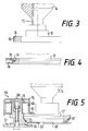
- Fig. 3
- eine Palette mit aufgesetztem Kops und Metallring mit Kunststoffschicht,
- Fig. 4
- die Vorderansicht einer Palette beim Transport entlang einer Elektromagnetanordnung,
- Fig. 5
- eine Vorderansicht einer Palette mit aufgesetztem Kops und mit abgeschrägter Unterkante der Grundplatte neben einem im Schnitt dargestellten Elektromagneten mit Abrollprofil,
- Fig. 1
- a branch on a transport track with an electromagnet arrangement for stopping, separating and branching off pallets,
- Fig. 2
- a section of a transport path with a stop and separating device consisting of an electromagnet and a stop element,
- Fig. 3
- a pallet with attached cop and metal ring with plastic layer,
- Fig. 4
- the front view of a pallet during transport along an electromagnet arrangement,
- Fig. 5
- 1 shows a front view of a pallet with a cop and a slanted lower edge of the base plate next to an electromagnet with a rolling profile, shown in section,
Beispiel bei einer Mehrpartienverarbeitung in Abhängigkeit von der Partie, zugeführt werden. Ebenso ist ein gleichmäßiges Verteilen der Kopse auf in die Spulmaschinensektionen integrierte Vorbereitungseinrichtungen möglich, deren Staustrecken gegebenenfalls über Sensoren überwacht werden.Example for multi-lot processing depending on the lot. It is also possible to evenly distribute the cops to preparation devices integrated in the winding machine sections, the stagnation distances of which may be monitored by sensors.
Ebenso ist die Anordnung einer derartigen Abzweigung an einer Rückführbahn der aus den Spulstellen ausgetragenen Paletten 13 denkbar. An einer solchen Stelle würden dann zum Beispiel Paletten abgezweigt, die noch Hülsen mit mehr oder weniger großem Bewicklungsrest oder auch zum Beispiel nicht vorbereitete Kopse tragen.The arrangement of such a branch on a return path of the
Die Paletten 13 werden entlang einer Transportbahn 58 mittels Reibschluß durch ein Transportband 58' transportiert. Dabei sind die Paletten 13 an ihren Grundplatten seitlich durch Führungskanten 56 und 57 geführt.The
Im vorliegenden Beispiel sind die Führungskanten 56 und 57 so ausgebildet, daß sie die Paletten 13 schon vor Erreichen eines ersten Elektromagneten 59 senkrecht zur Transportrichtung des Transportbandes 58' verschieben. Dabei wird durch eine relativ starke Richtungsänderung, insbesondere durch die Gestaltung der Führungskante 56, eine je nach Rückstaulänge mehr oder weniger starke Schubkraft der Paletten abgefangen, die dann nur noch wesentlich abgeschwächt im Bereich der Stopp-Position zwischen dem Elektromagneten 59 und einem stromab gelegenen weiteren Elektromagneten 60 wirkt. Hinzu kommt, daß die Paletten 13 durch diese Richtungsänderung nur noch mit einem Teil ihrer Grundfläche auf dem Transportband 58' aufliegen, wodurch sich die in dessen Transportrichtung wirkende Kraftkomponente ebenfalls verringert.In the present example, the
Durch die beschriebenen Führungskanten 56 und 57 werden die Paletten direkt einem Führungsprofil 73 des Elektromagneten 59 zugeleitet, auf dem sie unter der Wirkung der Magnetkraft abrollen. Dabei wird die Abrollbewegung durch das Transportband 58' noch unterstützt, auf dem die Palette 13 nur noch zum Teil aufliegt.Through the described
Ein Näherungssensor 61 erkennt die Ankunft beziehungsweise den Beginn des Abrollens einer Palette 63 auf dem Abrollprofil 73 des Elektromagneten 59. Durch seine Verbindung zu einer nicht dargestellten Steuereinheit wird das Aktivieren des Elektromagneten 60 mit einem Abrollprofil 75 bewirkt. Die Palette 13 nimmt dann eine stabile Lage zwischen den beiden Elektromagneten 59 und 60 ein, wobei sie an beiden Abrollprofilen 73 und 75 anliegt. Besonders vorteilhaft ist es, wenn ein Sensor 141 so angeordnet ist, daß er den auf der Palette 13 aufgesteckten Kops 14 beziehungsweise die Hülse 15 während der Ruhestellung der Palette 13, vorzugsweise fotooptisch, abtasten kann. Je nach Anordnung der Abzweigung kontrolliert der Sensor 141 die Partie des jeweiligen Kopses 14 beziehungsweise den auf der Hülse 15 noch befindlichen Bewicklungsrest.A
Dieser Sensor 141 übermittelt dann der nicht dargestellten Steuereinheit ein Signal, welches in der zentralen Steuereinheit nach vorgegebenen Kriterien bewertet wird und in ein Steuersignal für die Elektromagneten 59 und 60 gewandelt wird. Ist zum Beispiel der Weitertransport der Palette 13 entlang der Transportbahn 58 vorgesehen, können beide Elektromagnete 59 und 60 abgeschaltet werden. Dadurch wird die Palette 13 vom Transportband 58' mitgenommen und an der Abzweigung einer Transpoprtbahn 65 vorbeigeführt.This
Obwohl das Abrollprofil 75 des Magneten 60 die Palette 13 bereits wieder weiter auf das Transportband 58' verschiebt, kann hinter der Abzweigung eine hier nicht dargestellte weitere Führungskante 66 (siehe Fig. 2) die Palette 13 noch weiter in dieser Richtung verschieben.Although the rolling
Nach einer kurzen vorgebbaren Pause, die insbesondere durch die Transportgeschwindigkeit des Transportbandes 58' bestimmt wird, wird der Elektromagnet 59 wieder eingeschaltet, um die nachfolgende Palette 13 zu stoppen.After a brief, predeterminable pause, which is determined in particular by the transport speed of the
Liegen die vom Sensor 141 ermittelten Werte für den Kops 14 beziehungsweise die Hülse 15 außerhalb der an der zentralen Steuereinheit vorgegebenen Toleranzen, was ein Abzweigen der Palette in die Transportbahn 65 erforderlich macht, wird nach dem Abschalten des Elektromagneten 59 der Elektromagnet 60 noch unter Spannung gehalten. Dadurch rollt die Palette 13 so weit auf dem Abrollprofil 75 des Elektromagneten 60 ab, bis sie die zur Transportbahn 65 gehörige Führungskante 67 erreicht. Diese Palette 13 wird dann vom Transportband 65', welches durch eine Umlenkrolle 65'' umgelenkt und von einem nicht dargestellten Motor angetrieben wird, entlang der Transportbahn 65 weiter mitgenommen.If the values determined by the
Deckplatten 62 und 63 sind hauptsächlich dafür vorgesehen, zumindest einen Teil der Grundplatten der Paletten 13 so abzudecken, daß diese Paletten 13, zum Beispiel durch äußere Einwirkungen auf die Kopse 14 oder die Hülsen 15, nicht kippen können. Vom Maschinenrahmen ist hier lediglich das Rahmenteil 77 zu erkennen, an welchem unter anderem die Deckplatte 62 befestigt ist. Die Elektromagnete 59 und 60 sind mittels Befestigungsschrauben 68 und 74 am Grundrahmen 72 (siehe Fig. 5) befestigt.
Die Anordnung der beiden Elektromagnete 59 und 60 ermöglicht gleichzeitig ein Stoppen, Vereinzeln und gesteuertes Abzweigen von Paletten. Hier sind keine mechanisch bewegten Teile vorhanden, die direkt in den Transportweg ragen.The arrangement of the two
Die in Fig. 2 dargestellte Variante der Erfindung beschreibt eine Stopp- und Vereinzelungsvorrichtung für Paletten 13, die entlang eines Transportweges 58 angeordnet ist. Die Bahnführung entspricht dabei der im vorigen Ausführungsbeispiel beschriebenen. Allerdings ist der Elektromagnet 60 hier durch einen Stopper 64 ersetzt. Die jeweils in der Stopp-Position befindliche Palette 13 nimmt dabei eine stabile Lage zwischen dem Abrollprofil 73 des Elektromagneten 59 und dem Stopper 64 ein. Nach dem Abschalten des Elektromagneten 59 verläßt diese Palette 13 diese Position, indem sie durch die Reibkraft des Transportbandes 58' mitgenommen wird und vom Stopper auf ein Profil 66 abrollt, welches die Palette 13 dem normalen Transportweg 58 wieder zuführt.The variant of the invention shown in FIG. 2 describes a stop and separating device for
Gemäß diesem Ausführungsbeispiel ist es vorteilhaft, einen Näherungssensor 61' bereits stromauf zum Elektromagneten 59 anzuordnen, wenn nur dieser Elektromagnet 59 steuerbar ist.According to this exemplary embodiment, it is advantageous to arrange a proximity sensor 61 'upstream of the
Alle Näherungssensoren der bisherigen Ausführungsbeispiele können induktiv wirkende Sensoren sein, da die Paletten 13 in jedem Fall zumindest teilweise aus ferromagnetischem Material bestehen. Derartige Sensoren sind sehr zuverlässig und wenig kostenaufwendig.All proximity sensors of the previous exemplary embodiments can be inductively acting sensors, since the
Die Elektromagnete können sowohl auf ihrer Vorderseite eine zusammenhängende Abdeckung 35 als auch die Metallringe 34 der Paletten 13 eine Kunststoffschicht 55 tragen (s. Fig. 3). Auf diese Weise wird die Entstehung von Metallstaub beim Transport der Paletten 13 verhindert. Da sowohl die Dicke der Abdeckung 35 als auch die Dicke der Kunststoffschicht 55 sehr gering gehalten werden können, wird die Wirkung der Magnetkräfte kaum beeinträchtigt.The electromagnets can carry a
Die Fig. 4 zeigt eine Variante der Gestaltung des Metallringes 34'. Dabei ist die äußere Oberfläche dieses Metallringes 34' geringfügig zurückgesetzt. Auch dadurch wird ein Kontakt zur Magnetanordnung vermieden.4 shows a variant of the design of the metal ring 34 '. The outer surface of this metal ring 34 'is slightly set back. This also prevents contact with the magnet arrangement.
Die in Fig. 5 dargestellte Variante einer Palette 13'' mit Metallring 34'' weist den Vorteil auf, daß auch bei innerhalb eines Transportsystemes möglichen Abstufungen und Kanten kein Stau auftritt. Außerdem sind derartige Paletten geeignet, während ihres Transportes eine Richtungsänderung aus der Horizontalen oder in die Horizontale ohne Probleme zu gewährleisten.The variant of a
Die Fig. 5 zeigt des weiteren neben der Palette 13'' beispielhaft einen Elektromagneten 59 aus dem vorangehenden Ausführungsbeispiel gemäß Fig. 5 und Fig. 6. Dabei ist in dieser Figur deutlich zu erkennen, daß das Abrollprofil 73 der Form der Palette angepaßt ist.FIG. 5 further shows, in addition to the
Der Elektromagnet 59, der mittels einer Befestigungsschraube 68 am Grundrahmen 72 befestigt ist, besitzt ein Gehäuse 76. Zwischen diesem Gehäuse 76 und dem Eisenkern 70 des Elektromagneten ist eine Distanzscheibe 71 aus nichtleitendem Material angeordnet. Die Spule selbst ist mit 69 bezeichnet. Der Eisenkern 70, in den das Abrollprofil 73 eingearbeitet ist, besitzt auch noch eine Gleitplatte 63' für das Abstützen der jeweiligen Palette 13''.The
Wie diese Ausführungsbeispiele zeigen, liegen die einzigen drehenden Teile innerhalb des gesamten Transportsystemes, die Antriebs- und Umlenkrollen der Transportbänder, von denen die Paletten mittels Reibschluß innerhalb bestimmter Transportabschnitte transportiert werden, außerhalb dieser Transportabschnitte. Somit greifen bei diesen Beispielen keinerlei mechanisch bewegte Teile in die Transportbahnen ein, in denen sich Schleppfäden verfangen könnten.As these exemplary embodiments show, the only rotating parts within the entire transport system, the drive and deflection rollers of the conveyor belts, from which the pallets are transported by friction within certain transport sections, lie outside these transport sections. Thus, in these examples, no mechanically moving parts intervene in the transport tracks in which trailing threads could get caught.
Claims (15)
- A textile machine with an automatic transport system for transporting textile bobbins or tubes which are set up individually on pallets (13; 13'; 13''), along predetermined transport paths (58) with guide means (56, 57, 66, 67) for substantially lateral guidance of the pallets, characterised in that the pallets (13; 13'; 13'') are on their periphery provided with a metal ring (34; 34'; 34'') and in that in each case there is an electromagnet (28; 59, 60; 59') which is constructed as a convexly curved portion (73, 75) of the guide means and in that means are provided for the controlled activation of the electromagnet (28; 59, 60; 59').
- A textile machine according to Claim 1, characterised in that the electromagnet (59, 60; 59') is disposed on a transport path (58) having mechanical means (58) for transporting the pallets (13, 13', 13'') by frictional engagement.
- A textile machine according to Claim 1 or 2, characterised in that the electromagnet (60) is disposed on a branch of the transport path (58).
- A textile machine according to one of Claims 1 to 3, characterised in that two electromagnets (59, 60) are disposed at a distance from each other which is less than the diameter of the base plate of the pallets (13; 13'; 13'').
- A textile machine according to Claim 4, characterised in that the electromagnet (60) situated downstream on the transport path (58) is so disposed that its rolling profile (75) at the same time forms the inner deflecting edge for the pallets (13; 13'; 13'') into a branch path (65).
- A textile machine according to Claim 4 or 5, characterised in that there is between the magnets (59, 60) a proximity sensor (61) which is connected to a circuit which activates the magnet (60) when a pallet (13; 13'; 13'') arrives.
- A textile machine according to Claim 6, characterised in that the proximity sensor (61) has a circuit which, after recognising the fact that the pallet (13; 13'; 13'') has been removed by the magnet (59) being switched off, activates this magnet again.
- A textile machine according to one of Claims 4 to 7, characterised in that in the activated state, the magnets (59, 60) possess different polarity.
- A textile machine according to one of Claims 4 to 8, characterised in that on the transport path (58) in the region of the inoperative position of whichever pallet (13; 13'; 13'') has stopped and which is in between the magnets (59, 60) there is a sensor (141) which recognises special features of a cop (14) or tube (15) transported by the pallet, such as a winding residue or part and in that this sensor (141) has a switching connection to the downstream magnet (60) by which it is possible to control the period of time for which this magnet (60) is activated.
- A textile machine according to Claim 2, characterised in that downstream of the magnet (59) disposed along the transport path (58) and comprising a rolling profile (73) there is a stopping element (64) at a distance which is shorter than the diameter of the base plate of the pallets (13; 13'; 13'').
- A textile machine according to one of Claims 1 to 10, characterised in that guide edges (56, 57) for the pallets (13; 13'; 13'') upstream of the magnet (59) are so constructed that they displace the pallets on the transport path at right-angles to the transport direction and in the direction of this magnet.
- A textile machine according to Claim 11, characterised in that a further guide edge (66) is disposed downstream and displaces the pallets (13; 13'; 13'') away at right-angles to the direction of transport and away from the electromagnet (59, 60; 59').
- A textile machine according to Claim 1, characterised in that the means are constituted by a control arrangement by which the electromagnet (28; 59, 60; 59') can be activated in a time-related rhythm.
- A textile machine according to Claim 1, characterised in that the metal ring (34'') if the pallet (13'') has a chamfered edge.
- A textile machine according to Claim 6 or 7, characterised in that the proximity sensors (61; 61') are inductively acting sensors which recognise the pallets (13; 13'; 13'') from their metal rings (34; 34'; 34'').
Applications Claiming Priority (4)
| Application Number | Priority Date | Filing Date | Title |
|---|---|---|---|
| DE3919106 | 1989-06-10 | ||
| DE3919106 | 1989-06-10 | ||
| DE4011797 | 1990-04-12 | ||
| DE4011797A DE4011797C2 (en) | 1989-06-10 | 1990-04-12 | Transport system for an automatic textile machine for the controlled guidance of pallets along specified transport routes |
Publications (2)
| Publication Number | Publication Date |
|---|---|
| EP0402703A1 EP0402703A1 (en) | 1990-12-19 |
| EP0402703B1 true EP0402703B1 (en) | 1995-02-15 |
Family
ID=25881851
Family Applications (1)
| Application Number | Title | Priority Date | Filing Date |
|---|---|---|---|
| EP90110244A Expired - Lifetime EP0402703B1 (en) | 1989-06-10 | 1990-05-30 | Textile machine with an automatic tranport system to transport textile bobbins or spools |
Country Status (3)
| Country | Link |
|---|---|
| US (1) | US5190136A (en) |
| EP (1) | EP0402703B1 (en) |
| JP (1) | JP3100607B2 (en) |
Families Citing this family (30)
| Publication number | Priority date | Publication date | Assignee | Title |
|---|---|---|---|---|
| DE4019099A1 (en) * | 1990-06-15 | 1991-12-19 | Schlafhorst & Co W | Cop conveyor system - has retention location to revolve the cop for a time until a loose end is retrieved |
| DE4019475A1 (en) * | 1990-06-19 | 1992-01-02 | Schlafhorst & Co W | WINDING MACHINE WITH BOBBIN RECOVERY ARRANGED AT A CONTROL PANEL AT TABLE HEIGHT |
| DE4131518A1 (en) * | 1991-09-21 | 1993-03-25 | Schlafhorst & Co W | TRANSPORT SYSTEM FOR TRANSPORTING INDIVIDUAL CARRIERS |
| DE4131608A1 (en) * | 1991-09-23 | 1993-03-25 | Schlafhorst & Co W | METHOD FOR OPERATING AN AUTOMATIC WINDING MACHINE |
| DE4142790C2 (en) * | 1991-12-23 | 2001-12-13 | Schlafhorst & Co W | Head transport device in an automatic winder |
| DE4233819C2 (en) * | 1992-10-08 | 2003-05-08 | Schlafhorst & Co W | Method for operating an automatic winding machine when changing lots |
| DE4312855A1 (en) * | 1993-04-22 | 1994-10-27 | Schlafhorst & Co W | Loading and unloading station for the loading and unloading of trolleys onto the attachment mandrels of which textile bobbins or textile-bobbin tubes are slipped |
| DE4338552C2 (en) * | 1993-11-11 | 2002-08-01 | Schlafhorst & Co W | Textile machine producing cross-wound bobbins with a large number of bobbins arranged in series |
| DE19518276A1 (en) * | 1995-05-18 | 1996-11-21 | Schlafhorst & Co W | Material movement system in automatic spinning machine |
| DE29605595U1 (en) * | 1995-09-20 | 1997-02-13 | Brain Power Consulting Gmbh | Plant for processing vessels, transport device for transporting vessels and pallets therefor |
| US6227348B1 (en) | 1996-01-26 | 2001-05-08 | Elpatronic Ag | Method and apparatus for separating and bringing together series of container bodies |
| DE19636661A1 (en) * | 1996-09-10 | 1998-03-12 | Schlafhorst & Co W | Transport system for a textile machine |
| US6047854A (en) * | 1997-02-26 | 2000-04-11 | Sarnoff Corporation | Bead dispersement devices |
| JPH1159901A (en) * | 1997-08-11 | 1999-03-02 | Murata Mach Ltd | Carrier moving device |
| DE19816232A1 (en) * | 1998-04-10 | 1999-10-14 | Schlafhorst & Co W | Transport system for spinning bobbins and bobbin tubes with a transport path spanning one passage |
| DE19902338B4 (en) * | 1999-01-21 | 2004-10-14 | Steag Hamatech Ag | Lifting device for substrates |
| JP4855151B2 (en) * | 2006-06-09 | 2012-01-18 | 三菱電機株式会社 | Bearing device |
| DE102007014876B4 (en) * | 2007-03-26 | 2010-04-08 | Kba-Metronic Aktiengesellschaft | transport system |
| CN103540518B (en) | 2010-07-23 | 2015-07-08 | 贝克曼考尔特公司 | Test box |
| US8973736B2 (en) | 2011-11-07 | 2015-03-10 | Beckman Coulter, Inc. | Magnetic damping for specimen transport system |
| CN104053997B (en) | 2011-11-07 | 2016-12-21 | 贝克曼考尔特公司 | For processing the system and method for sample |
| WO2013070754A1 (en) | 2011-11-07 | 2013-05-16 | Beckman Coulter, Inc. | Robotic arm |
| BR112014011046A2 (en) | 2011-11-07 | 2017-06-13 | Beckman Coulter, Inc. | workflow and centrifuge system |
| KR20140091033A (en) | 2011-11-07 | 2014-07-18 | 베크만 컬터, 인코포레이티드 | Specimen container detection |
| WO2013070740A1 (en) | 2011-11-07 | 2013-05-16 | Beckman Coulter, Inc. | Aliquotter system and workflow |
| DE102013218389B4 (en) * | 2013-09-13 | 2023-01-12 | Krones Ag | Device and method for switching a passive switch for transport systems with linear motors |
| KR101656784B1 (en) * | 2014-12-03 | 2016-09-12 | 주식회사 대경 | a book |
| ITPO20150002A1 (en) * | 2015-02-06 | 2016-08-06 | Ecafil Best Spa Ind Filati | SYSTEM AND METHOD OF CONTROL AND PROGRAMMING OF THE PRODUCTION OF A BALL |
| JP6697911B2 (en) * | 2016-03-18 | 2020-05-27 | 日立造船株式会社 | Electron beam sterilization equipment |
| US10427162B2 (en) | 2016-12-21 | 2019-10-01 | Quandx Inc. | Systems and methods for molecular diagnostics |
Family Cites Families (12)
| Publication number | Priority date | Publication date | Assignee | Title |
|---|---|---|---|---|
| US2264348A (en) * | 1939-09-16 | 1941-12-02 | American Can Co | Can conveyer |
| US3092237A (en) * | 1961-03-06 | 1963-06-04 | Ways & Means Inc | Conveyor arrangement |
| US3167168A (en) * | 1963-08-15 | 1965-01-26 | Chester P Park | Electromagnetic conveyor |
| US3621979A (en) * | 1968-12-05 | 1971-11-23 | Robert W Kraeft | Magnetic conveyor system |
| FR2136970B1 (en) * | 1971-05-10 | 1973-05-11 | Webb Co Jervis B | |
| US3941237A (en) * | 1973-12-28 | 1976-03-02 | Carter-Wallace, Inc. | Puck for and method of magnetic conveying |
| DE2801387A1 (en) * | 1978-01-13 | 1979-07-19 | Bernhard Heuft | SORTING MACHINE |
| JPS5917464A (en) * | 1982-07-19 | 1984-01-28 | Murata Mach Ltd | Different kind tube string carry system |
| JPS5922862A (en) * | 1982-07-23 | 1984-02-06 | Murata Mach Ltd | Cop transport system |
| US4681231A (en) * | 1982-12-08 | 1987-07-21 | Murata Kikai Kabushiki Kaisha | Article selecting and conveying system |
| US4605177A (en) * | 1983-09-20 | 1986-08-12 | Murata Kikai Kabushiki Kaisha | Bobbin transporting and treating system |
| US4940127A (en) * | 1986-12-12 | 1990-07-10 | Murata Kikai Kabushiki Kaisha | Wound yarn package transporting system |
-
1990
- 1990-05-30 EP EP90110244A patent/EP0402703B1/en not_active Expired - Lifetime
- 1990-06-11 US US07/535,884 patent/US5190136A/en not_active Expired - Fee Related
- 1990-06-11 JP JP02150102A patent/JP3100607B2/en not_active Expired - Fee Related
Also Published As
| Publication number | Publication date |
|---|---|
| US5190136A (en) | 1993-03-02 |
| EP0402703A1 (en) | 1990-12-19 |
| JPH03102013A (en) | 1991-04-26 |
| JP3100607B2 (en) | 2000-10-16 |
Similar Documents
| Publication | Publication Date | Title |
|---|---|---|
| EP0402703B1 (en) | Textile machine with an automatic tranport system to transport textile bobbins or spools | |
| DE4011797C2 (en) | Transport system for an automatic textile machine for the controlled guidance of pallets along specified transport routes | |
| EP0868227B1 (en) | Device and process for intermediate stacking of letters | |
| EP0402630B1 (en) | Automatic winder with a cops and tubes transport system with several transport loops | |
| EP0286080B1 (en) | Device for controlling the transfer of objects | |
| CH666878A5 (en) | DEVICE FOR SELECTING AND PROMOTING COPS. | |
| EP0463443B1 (en) | Device for positioning of bobbins placed on independent individual carriers and turning them around their vertical axis | |
| DE3326537C2 (en) | Restraint | |
| EP0406541B1 (en) | Automatic winding machine with a transport system in which cans or tubes are put in an upright position on pallets | |
| DE3742348A1 (en) | THREAD END SEARCH | |
| DE3407804C2 (en) | ||
| EP0175150A1 (en) | Sheet feeder | |
| DE3026075C2 (en) | Bobbin changing device on spinning machines | |
| DE4041715A1 (en) | TRANSPORT SYSTEM OF AN AUTOMATIC WINDING MACHINE | |
| DE4124061C2 (en) | Conveyor device with two upright flat belt conveyors | |
| DE4430611A1 (en) | Device for recognizing conveyed goods on conveyor tracks, in particular of packaged goods in roller conveyors | |
| EP0461569A2 (en) | Transport device for independent pallets carrying bobbins or cores | |
| EP0915051A1 (en) | Method and device for forming a stream of overlapping articles | |
| EP0402731B1 (en) | Automatic winder with a closed loop pin and cup transport-system | |
| DE4142620C2 (en) | Device for removing coil sleeves attached to transport plates | |
| DE3622004C2 (en) | ||
| DE3446461C2 (en) | ||
| EP0534184B1 (en) | Transporting system for transporting individual carriers | |
| DE4142790C2 (en) | Head transport device in an automatic winder | |
| DE4224086C2 (en) | Bobbin supply unit for supplying a winding machine with cops of different batches of yarn |
Legal Events
| Date | Code | Title | Description |
|---|---|---|---|
| PUAI | Public reference made under article 153(3) epc to a published international application that has entered the european phase |
Free format text: ORIGINAL CODE: 0009012 |
|
| AK | Designated contracting states |
Kind code of ref document: A1 Designated state(s): CH DE FR IT LI |
|
| 17P | Request for examination filed |
Effective date: 19910429 |
|
| 17Q | First examination report despatched |
Effective date: 19921104 |
|
| ITF | It: translation for a ep patent filed |
Owner name: DE DOMINICIS & MAYER S.R.L. |
|
| GRAA | (expected) grant |
Free format text: ORIGINAL CODE: 0009210 |
|
| AK | Designated contracting states |
Kind code of ref document: B1 Designated state(s): CH DE FR IT LI |
|
| REF | Corresponds to: |
Ref document number: 59008458 Country of ref document: DE Date of ref document: 19950323 |
|
| ET | Fr: translation filed | ||
| PLBE | No opposition filed within time limit |
Free format text: ORIGINAL CODE: 0009261 |
|
| STAA | Information on the status of an ep patent application or granted ep patent |
Free format text: STATUS: NO OPPOSITION FILED WITHIN TIME LIMIT |
|
| 26N | No opposition filed | ||
| PGFP | Annual fee paid to national office [announced via postgrant information from national office to epo] |
Ref country code: FR Payment date: 19990518 Year of fee payment: 10 |
|
| PG25 | Lapsed in a contracting state [announced via postgrant information from national office to epo] |
Ref country code: FR Free format text: LAPSE BECAUSE OF NON-PAYMENT OF DUE FEES Effective date: 20010131 |
|
| REG | Reference to a national code |
Ref country code: FR Ref legal event code: ST |
|
| PGFP | Annual fee paid to national office [announced via postgrant information from national office to epo] |
Ref country code: CH Payment date: 20040527 Year of fee payment: 15 |
|
| PG25 | Lapsed in a contracting state [announced via postgrant information from national office to epo] |
Ref country code: CH Free format text: LAPSE BECAUSE OF NON-PAYMENT OF DUE FEES Effective date: 20050531 Ref country code: LI Free format text: LAPSE BECAUSE OF NON-PAYMENT OF DUE FEES Effective date: 20050531 |
|
| REG | Reference to a national code |
Ref country code: CH Ref legal event code: PL |
|
| PGFP | Annual fee paid to national office [announced via postgrant information from national office to epo] |
Ref country code: DE Payment date: 20060707 Year of fee payment: 17 |
|
| PGFP | Annual fee paid to national office [announced via postgrant information from national office to epo] |
Ref country code: IT Payment date: 20070531 Year of fee payment: 18 |
|
| PG25 | Lapsed in a contracting state [announced via postgrant information from national office to epo] |
Ref country code: DE Free format text: LAPSE BECAUSE OF NON-PAYMENT OF DUE FEES Effective date: 20071201 |
|
| PG25 | Lapsed in a contracting state [announced via postgrant information from national office to epo] |
Ref country code: IT Free format text: LAPSE BECAUSE OF NON-PAYMENT OF DUE FEES Effective date: 20080530 |