EP0003111B1 - Device for the lateral deviation of selected objects from a first conveying device constructed a conveyor band to a second conveying device - Google Patents
Device for the lateral deviation of selected objects from a first conveying device constructed a conveyor band to a second conveying device Download PDFInfo
- Publication number
- EP0003111B1 EP0003111B1 EP79100027A EP79100027A EP0003111B1 EP 0003111 B1 EP0003111 B1 EP 0003111B1 EP 79100027 A EP79100027 A EP 79100027A EP 79100027 A EP79100027 A EP 79100027A EP 0003111 B1 EP0003111 B1 EP 0003111B1
- Authority
- EP
- European Patent Office
- Prior art keywords
- deflecting
- segments
- segment
- objects
- extended
- Prior art date
- Legal status (The legal status is an assumption and is not a legal conclusion. Google has not performed a legal analysis and makes no representation as to the accuracy of the status listed.)
- Expired
Links
- 230000004888 barrier function Effects 0.000 claims description 52
- 230000033001 locomotion Effects 0.000 claims description 8
- 230000004044 response Effects 0.000 claims description 5
- 239000012530 fluid Substances 0.000 claims 1
- 230000001939 inductive effect Effects 0.000 description 6
- 230000007704 transition Effects 0.000 description 6
- 238000000034 method Methods 0.000 description 5
- 229910000831 Steel Inorganic materials 0.000 description 4
- 230000008901 benefit Effects 0.000 description 4
- 235000013361 beverage Nutrition 0.000 description 4
- 230000002950 deficient Effects 0.000 description 4
- 238000011049 filling Methods 0.000 description 4
- 210000003739 neck Anatomy 0.000 description 4
- 230000011664 signaling Effects 0.000 description 4
- 239000010959 steel Substances 0.000 description 4
- 230000003111 delayed effect Effects 0.000 description 3
- 238000004519 manufacturing process Methods 0.000 description 3
- 230000008569 process Effects 0.000 description 3
- 230000003068 static effect Effects 0.000 description 3
- 230000006835 compression Effects 0.000 description 2
- 238000007906 compression Methods 0.000 description 2
- 230000009467 reduction Effects 0.000 description 2
- 230000001154 acute effect Effects 0.000 description 1
- 230000006978 adaptation Effects 0.000 description 1
- 238000013459 approach Methods 0.000 description 1
- 230000008859 change Effects 0.000 description 1
- 239000011248 coating agent Substances 0.000 description 1
- 238000000576 coating method Methods 0.000 description 1
- 230000006378 damage Effects 0.000 description 1
- 238000013016 damping Methods 0.000 description 1
- 230000007423 decrease Effects 0.000 description 1
- 238000001514 detection method Methods 0.000 description 1
- 230000009977 dual effect Effects 0.000 description 1
- 238000011156 evaluation Methods 0.000 description 1
- 230000002349 favourable effect Effects 0.000 description 1
- 239000011521 glass Substances 0.000 description 1
- 239000004519 grease Substances 0.000 description 1
- 230000001771 impaired effect Effects 0.000 description 1
- 239000003999 initiator Substances 0.000 description 1
- 238000002372 labelling Methods 0.000 description 1
- 239000007788 liquid Substances 0.000 description 1
- 230000007257 malfunction Effects 0.000 description 1
- 239000002184 metal Substances 0.000 description 1
- 238000002156 mixing Methods 0.000 description 1
- 238000005381 potential energy Methods 0.000 description 1
- 230000000750 progressive effect Effects 0.000 description 1
- 230000006641 stabilisation Effects 0.000 description 1
- 238000011105 stabilization Methods 0.000 description 1
- 239000007858 starting material Substances 0.000 description 1
- 239000000725 suspension Substances 0.000 description 1
Images


Classifications
-
- B—PERFORMING OPERATIONS; TRANSPORTING
- B07—SEPARATING SOLIDS FROM SOLIDS; SORTING
- B07C—POSTAL SORTING; SORTING INDIVIDUAL ARTICLES, OR BULK MATERIAL FIT TO BE SORTED PIECE-MEAL, e.g. BY PICKING
- B07C5/00—Sorting according to a characteristic or feature of the articles or material being sorted, e.g. by control effected by devices which detect or measure such characteristic or feature; Sorting by manually actuated devices, e.g. switches
- B07C5/36—Sorting apparatus characterised by the means used for distribution
- B07C5/363—Sorting apparatus characterised by the means used for distribution by means of air
- B07C5/365—Sorting apparatus characterised by the means used for distribution by means of air using a single separation means
-
- B—PERFORMING OPERATIONS; TRANSPORTING
- B07—SEPARATING SOLIDS FROM SOLIDS; SORTING
- B07C—POSTAL SORTING; SORTING INDIVIDUAL ARTICLES, OR BULK MATERIAL FIT TO BE SORTED PIECE-MEAL, e.g. BY PICKING
- B07C5/00—Sorting according to a characteristic or feature of the articles or material being sorted, e.g. by control effected by devices which detect or measure such characteristic or feature; Sorting by manually actuated devices, e.g. switches
- B07C5/36—Sorting apparatus characterised by the means used for distribution
- B07C5/361—Processing or control devices therefor, e.g. escort memory
- B07C5/362—Separating or distributor mechanisms
-
- B—PERFORMING OPERATIONS; TRANSPORTING
- B07—SEPARATING SOLIDS FROM SOLIDS; SORTING
- B07C—POSTAL SORTING; SORTING INDIVIDUAL ARTICLES, OR BULK MATERIAL FIT TO BE SORTED PIECE-MEAL, e.g. BY PICKING
- B07C5/00—Sorting according to a characteristic or feature of the articles or material being sorted, e.g. by control effected by devices which detect or measure such characteristic or feature; Sorting by manually actuated devices, e.g. switches
- B07C5/36—Sorting apparatus characterised by the means used for distribution
- B07C5/363—Sorting apparatus characterised by the means used for distribution by means of air
- B07C5/367—Sorting apparatus characterised by the means used for distribution by means of air using a plurality of separation means
-
- B—PERFORMING OPERATIONS; TRANSPORTING
- B65—CONVEYING; PACKING; STORING; HANDLING THIN OR FILAMENTARY MATERIAL
- B65G—TRANSPORT OR STORAGE DEVICES, e.g. CONVEYORS FOR LOADING OR TIPPING, SHOP CONVEYOR SYSTEMS OR PNEUMATIC TUBE CONVEYORS
- B65G47/00—Article or material-handling devices associated with conveyors; Methods employing such devices
- B65G47/52—Devices for transferring articles or materials between conveyors i.e. discharging or feeding devices
- B65G47/525—Devices for transferring articles or materials between conveyors i.e. discharging or feeding devices using fluid jets
-
- B—PERFORMING OPERATIONS; TRANSPORTING
- B65—CONVEYING; PACKING; STORING; HANDLING THIN OR FILAMENTARY MATERIAL
- B65G—TRANSPORT OR STORAGE DEVICES, e.g. CONVEYORS FOR LOADING OR TIPPING, SHOP CONVEYOR SYSTEMS OR PNEUMATIC TUBE CONVEYORS
- B65G47/00—Article or material-handling devices associated with conveyors; Methods employing such devices
- B65G47/52—Devices for transferring articles or materials between conveyors i.e. discharging or feeding devices
- B65G47/68—Devices for transferring articles or materials between conveyors i.e. discharging or feeding devices adapted to receive articles arriving in one layer from one conveyor lane and to transfer them in individual layers to more than one conveyor lane or to one broader conveyor lane, or vice versa, e.g. combining the flows of articles conveyed by more than one conveyor
- B65G47/71—Devices for transferring articles or materials between conveyors i.e. discharging or feeding devices adapted to receive articles arriving in one layer from one conveyor lane and to transfer them in individual layers to more than one conveyor lane or to one broader conveyor lane, or vice versa, e.g. combining the flows of articles conveyed by more than one conveyor the articles being discharged or distributed to several distinct separate conveyors or to a broader conveyor lane
-
- B—PERFORMING OPERATIONS; TRANSPORTING
- B65—CONVEYING; PACKING; STORING; HANDLING THIN OR FILAMENTARY MATERIAL
- B65G—TRANSPORT OR STORAGE DEVICES, e.g. CONVEYORS FOR LOADING OR TIPPING, SHOP CONVEYOR SYSTEMS OR PNEUMATIC TUBE CONVEYORS
- B65G2201/00—Indexing codes relating to handling devices, e.g. conveyors, characterised by the type of product or load being conveyed or handled
- B65G2201/02—Articles
- B65G2201/0235—Containers
- B65G2201/0244—Bottles
Definitions
- the invention relates to a device for the lateral deflection of certain objects selected according to a feature from a first transport device formed by a conveyor belt to a second transport device of the deflected objects.
- Devices of this type are contained, for example, in systems which fill liquids into containers such as bottles and are used to separate out defective containers, for example bottles which are not completely filled or are not properly closed, and which are not suitable for sale.
- a device is known from DE-A-2 437 798.
- the deflection device consists of a wedge-shaped ejector that pushes or deflects the selected objects onto the second transport device.
- the known deflection device is limited in its working speed. This results in particular from the fact that the length of the wedge in the conveying direction must not be significantly greater than the diameter of the bottles, since otherwise closely spaced bottles can no longer be selectively deflected or let through.
- a short length of the wedge is only possible if the bottles are deflected at a relatively large angle, which in turn is only possible at relatively low speeds of the transport devices.
- a deflection device with moving deflection segments is known from US-A-3361 247, the first transport device consisting of a link belt, in which each link is connected to a displaceable deflection segment, and a plurality of deflection segments together which are at an angle to the first transport device Deflection surface forms.
- the disadvantage here is that the individual deflection segments are in motion at the time when an object to be deflected hits them. Objects with low stability, such as bottles, are easily knocked over.
- the known deflection device also requires a very large mechanical effort, since the entire link belt must be equipped with deflection segments.
- a deflection device is also known from DE-A-2 358 185, in which the objects, for example the bottles, are displaced onto the second transport device by deflecting segments which move with the first transport device.
- the deflection segments are guided through a switch to a guide track, through which they are moved transversely to the conveying direction.
- their width must correspond approximately to the diameter of the objects.
- the items to be separated out must also not arrive in close succession, but must be separated by a suitable facility, i. H. the distance between the objects must have a certain minimum size.
- the known device therefore inevitably has a relatively large dimension, which, for example, makes it difficult to discharge the objects onto so-called turntables.
- a device for deflecting objects is known from DE-A-2 555 192, the transport device consisting of individual narrow belts which run over rollers. The objects are deflected by a comb, which is pushed upwards between the belts. This device is only applicable in cases where the distance between the individual objects is relatively large.
- US-A-3 512 638 describes a deflection device, particularly for packages and similar containers.
- the transport devices consist of roller tracks, the first roller track describing a curve in the deflection area.
- the deflecting segments are formed by deflecting rollers which can be extended vertically between two rollers.
- the rollers of the transport path In order to prevent the packages or other objects from getting caught on the unrolling, the rollers of the transport path must have thickened areas and certain of these rollers must have a friction-increased coating.
- the individual deflection rollers are controlled by separate light barriers. The disadvantage here is that this deflection device can only be used with roller tracks, but not with transport devices with a closed surface, such as link belts or steel belts.
- a deflection device with roller conveyors as a transport device is described in the publication "Branches in Horizontal Conveyor Lines", in “Conveying and Lifting", Volume 21, 1971, pages 232-236.
- the selected objects are deflected by swiveling the rollers.
- the invention achieves the object of providing a device for the lateral deflection of certain objects selected by a feature from a first transport device to a second transport device, which has a very high working speed and on the transport devices themselves no special equipment required.
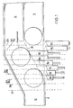
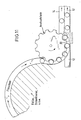
- the deflection device shown in Fig. 1 has a first transport device 12 and a second transport device 14 which, for. B. can consist of a steel or plastic link chain.
- the transport devices are laterally limited by railings 15, 16 and 17.
- the second transport device runs parallel and immediately adjacent to the first transport device. In a certain area, the so-called deflection section, the railings are interrupted or angled to enable objects to be transferred from the first transport device to the second transport device.
- three objects are shown, of which the mit ⁇ lere separated, i. H. is to be deflected or diverted while the first and third objects are to be conveyed further on the first transport device.
- the middle object is carried on by the second transport device.
- a selected object is deflected by Seg. elements 18n (n stands for a, b, c ).
- the segments are fixed in the conveying device of the transport devices and can be extended approximately perpendicular to this conveying direction.
- the segments are preferably extended approximately in the direction the bisector of the obtuse angle formed by the deflection surface 30 and the first transport device 12.
- the segments can consist of a vertical bracket 20 and several horizontal fingers 22.
- the length of the horizontal fingers 22 is preferably determined by the extension paths of the individual segments, so that the railing 16 interrupted at the deflection section can be replaced by one or more guide rods 23 which guide the objects cleanly when the individual segments are retracted.
- the deflection path is the area delimited by the first and last segment.
- Each segment 18 is connected to the piston 25 of a pneumatic cylinder 26 by a shaft 24. Depending on the position of a solenoid control valve 28, the segment is extended or retracted.
- the attack surfaces of the segments for. B. the front edges of the fingers 22, a deflecting surface 30 through which the selected objects are deflected onto the second transport device.
- the segments can be extended to different extents and the contact surface of the segments is opposite. bevelled towards the conveying direction.
- the segment 18a is extended so far that its contact surface is flush with the railing 16
- the remaining segments 18b to 18h are extended so far that their contact surface is flush with the contact surface of the preceding segment.
- the first segments e.g. 3. 18a to 18c, preferably have a curved engagement surface, so that the railing 16 merges into the deflection surface 30 in a smooth curve.
- the smooth transition of the railing 16 into the deflecting surface 30 enables a bumpless deflection of the selected objects even at high working speeds.
- the length of the segments 18n depends on the dimension of the objects in the conveying direction and the distance of the objects from one another.
- the width of the segments is preferably less than about half or about a third of the distance between the leading edges of successive objects. If the objects follow each other immediately, the width of the individual segments should not be greater than about half the dimension of the objects in the conveying direction.
- the segment width should preferably be smaller than about a third of this dimension.
- the segments do not have to have the same width and the first segments can e.g. B. have a slightly larger width.
- the number of segments depends on the size of the objects and the conveying speed.
- the segments are moved in the plane of the transport devices and perpendicular to the conveying direction. However, it is also possible to retract the segments vertically from above.
- the segments can have individual fingers 22 or the contact surface of the segments can be formed by a closed metal or plastic surface.
- the angle which the deflection surfaces 30 forms with the conveying direction of the first transport device 12 depends on the conveying speed and is smaller the higher the conveying speed.
- An air cushion between the objects and the segments can be formed by fine air nozzles in the surface of the segments. Such an air cushion can reduce the friction between the objects and the contact surfaces of the segments and even accelerate an object to be deflected in the deflection direction. Air cushions of this type also avoid the partial overtaking of a deflected object by a subsequent object, since the deflected object is not braked.
- Fig. 1 only a number of segments are shown, which are located on the lower edge of the first transport device in the figure.
- the inclined railing 15 can also be replaced by a series of segments, the contact surfaces of which run parallel to the conveying direction of the first transport device and which are controlled so that they have a fixed distance which corresponds to the width of the first transport device, own of the segments 18n.
- the further segments can be firmly connected to the segments 18n while maintaining this distance. If a jam occurs in the first transport device downstream of the deflection device, such a row of second segments is particularly advantageous since it prevents the objects from being inadvertently diverted onto the second transport device.
- the extension of the segments represents a pure translational movement.
- the segments are extended based on a rotational movement (FIGS. 5, 6 and 10).
- the segments 58n are individually rotatable on an axis 51 which is vertical, approximately at the height of the first segment 58a, directly adjacent to the first transposing device.
- Each segment is extended by a pneumatic cylinder or by an electromagnet 55 which, in order to take advantage of the leverage, acts close to the axis of rotation.
- the segments themselves consist of preferably two angles 57, each of which has a leg 52 which is bent concentrically to the pivot point. These curved legs of the two angles end at a vertical bracket 56 which has on the opposite side one or more risers (sliding lugs 59), along which the objects can slide.
- Bracket and sliding lugs form an acute angle with the radius vector to the segment tip such that when segments are retracted in the conveying direction there is a smooth plane which then inevitably merges into a smooth deflection plane at any angle to the conveying direction by pivoting out the individual segments.
- an axis of rotation lying horizontally next to the first transport device is also possible as a suspension for the railing segments.
- This axis of rotation can be located both in the plane given by the surface of the transport devices and above or below this plane; the direction of the axis of rotation can be parallel to the conveying direction or to the deflection surface or can also assume an intermediate value;
- those segments are in the extended state which attack the selected object at the relevant time or immediately thereafter.
- those segments that do not collide with the immediately preceding and the immediately following object that remain on the first transport device can be in the extended state at any time. As a result, the maximum number of segments is in the extended state during a deflection process.
- test takes place on the test line 32, which is preferably located directly in front of the deflection path. If the test is carried out earlier, it must be carried out by suitable means, e.g. B. a shift register, time delayed or stored so that the test result of the control device for the segments is supplied at the time when the object in question enters the deflection path.
- suitable means e.g. B. a shift register, time delayed or stored so that the test result of the control device for the segments is supplied at the time when the object in question enters the deflection path.
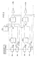
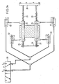
- the device for controlling the segments has the test devices mentioned above, light barriers 34a to 34h for generating a drive-in command, light barriers 35a to 35h for clearing the respective segment and control electronics (FIG. 2).
- the control device shown in FIGS. 1 and 2 the alternative is shown in which the maximum number of segments is extended, ie all segments that do not collide with the immediately preceding and the immediately following object that are not to be deflected .
- the light barrier 35a emits a clear message after the passage of the object that precedes the object to be deflected.
- the free message t delayed by a time element 40a at a time and applied to the set input of flip-flop 1a.
- the amount of the time delay depends on the speed of the first transport device, the response time of the control device and the position of the light barrier 35a.
- the free report is a prerequisite for extending a segment and the time delay should be such that the object from which the free report is derived is no longer hit by the segment that then exits on the basis of the free report.
- the time delay then depends on the speed of the transportation device. Since the transport speed can change during operation, the delay introduced by the timer 40a is preferably variable. With a low transport speed, the time delay is greater than with a high transport speed.
- the signal obtained at the normal output of the flip-flop 1a is fed to the set input of a flip-flop 2a via an AND gate 41a.
- the second input of the AND gate 41a is connected to the normal output of a flip-flop 0, which is set by the test device and g. B. is in the set state if the object that follows the object from which the free notification was to be sorted out, since it z. B. is faulty.
- the normal output of the flip-flop 2a controls a control valve 28 via a power driver. B. actuates a pneumatic cylinder 26 which extends the segment 18a.
- the segment 18a is always extended when an object to be deflected approaches this segment and the immediately preceding object has already moved past this segment.
- the control electronics assigned to the segment 18b is apart from the fact that the second input of the AND gate 41b is not included the flip-flop 0, but is connected to the normal output of the flip-flop 2a, identical to the control electronics assigned to the segment 18a.
- the segment 18b is accordingly extended when there is a free signal from the light barrier assigned to this segment and when the segment 18a is extended.
- the control electronics of the other segments is analogous to that of segment 18b. Any segment is therefore extended if there is a free message for this segment and the preceding segment is extended.
- An entry command is derived from the front edge of each object by further light barriers 34n.
- a light barrier 34n for the entry command is also assigned to each segment 18n.
- the move-in command is delayed via timers 44n.
- the light barrier 34n for the entry command of a segment is located approximately one segment width in front of the light barrier for the free signaling of the relevant segment if timers 40n and 44n are used with the same time delay.
- the output of the timer 44a is connected to one input of an AND gate 42a.
- the other input of the AND gate 42a is connected to the inverted output of the flip-flop 0.
- the flip-flop 1a and the flip-flop 2a are reset by an L output signal from the AND gate 42a.
- the UNC member 42a has a dual function: first, it prevents unnecessary retraction of the segments if two successive objects are to be deflected, and second, it prevents the retract command derived from an object to be deflected, a segment is retracted before this object has moved past this segment.
- the segment 18b is retracted when the relevant entry command light barrier 34b is interrupted by an object and the preceding segment 18a is retracted, ie the flip-flop 2a is reset.
- the segments 18c to 18h are retracted under analog conditions.
- the control device works in such a way that by the last error-free object, for. B. the first five segments 18a to 18e are registered. If the test device then detects a defective object, flip-flop 0 is set and the first five segments are extended practically simultaneously.
- the segments 18f, 18g etc. are only extended when they are also registered, ie the release command light barriers 35f, 35g etc. assigned to them are no longer interrupted by the last fault-free object.
- the light barriers 34a to 34h and 35a to 35h are located on the lines correspondingly designated in FIG. 1.
- the broken lines which are denoted by 34a to 34h and by 35a to 35h, do not represent the actual scanning lines, ie the position of the light barriers, but rather mark the position at which the leading edge or trailing edge of the controlling object is located at the moment of the scanning, ie the generation of the control pulse.
- the actual position of the light barriers must take into account the conveying speed and the response time of the cylinders and valves as well as the extension and retraction times of the segments.
- the light barriers must therefore be arranged a distance in front of the assigned segments, which essentially results from the product of the conveying speed and the sum of the response time and the extension or retraction time.
- a free signaling light barrier (dark-light transition) and an entry command light barrier (light-dark transition) are normally required for each segment. If the extension time of segment n is approximately in the same order of magnitude as the entry time of segment n + 1, then the free-signal light barrier of n and the entry command light barrier of n + 1, as shown in FIG. 1, can be combined into a single light barrier summarize, from whose output signal ' by differentiating the flank corresponding to the light-dark transition becomes the entry pulse and the flank E corresponding to the dark-light transition becomes the vacant signaling pulse.
- the position of the scanning systems must be selected so that. given shape and distance of the objects, the individual objects can be safely distinguished from each other (resolved) and the trigger impulses (free messages, entry commands) can be reproduced with a certain accuracy, which essentially depends on the speed of the objects.
- the direction of the light barriers corresponds approximately to that of the bisector of the obtuse angle formed by the deflection plane and the first transport device.
- Objects which do not together form a continuous edge 36 running in the conveying direction can be scanned by means of light barriers (FIG. 7) which run obliquely upwards or downwards (FIG. 7).
- B. cylindrical objects such as cans. Objects that do not form a continuous closed surface together can be scanned from above with suitable reflective light barriers from the discharge side (FIG. 8).
- the principle of control on predecessor and successor enables a particularly favorable light barrier arrangement shown in FIG. 9.
- the light barrier transmitters 93b to 93h and 94a to 94g are integrated in the fingers 22.
- the transmitters can e.g. B. be infrared LEDs, but can also be light guides that lead to fixed light barrier units.
- the beam directions of the light barrier transmitters 93b to 93h that supply the entry commands run from the transmitters in the individual segments preferably parallel to the deflection surface to a first light barrier receiver block 91
- Light barrier receiver block 92 The assignment of the light barriers is selected such that each of the segments 18b to 18h is retracted by an approaching object that cannot be diverted by the signal of its entrance light barrier and each of the segments 18a to 18g the next segment depending on the object to be diverted previous object is released or extended.
- the first segment 18a is controlled by the test light barrier (test line 32).
- the position of transmitter and receiver can also be interchanged so that blocks 91 and 92 are transmitters and the receivers are in the segments.
- the course of the individual objects can also be followed by inductive or capacitive proximity switches, ultrasonic, air barriers etc. or with video (CCD) cameras.
- CCD video
- Such camera systems are not only used for objects that are difficult to resolve, but also for deflection devices that have to process different embodiments of certain objects in alternating operation (e.g. fill level and closure control in beverage filling systems that can be set on several types of bottles).
- the segments are extended at the earliest possible date and are no longer in motion when the object to be deflected hits a segment. This prevents the objects from being knocked over by the moving segments.
- the fact that only a subsequent object gives the command to retract the segments ensures that, on the one hand, an object is diverted through the deflecting surface formed by the segments when the distances between the objects are greater, and on the other hand with certainty when the distances between the objects are small and the sequence is close last segments are retracted so that they do not hinder the transport of the objects.
- Another advantage is that in the case of several objects which are deflected one after the other, regardless of the distances between these objects, the segments are extended only once and the next object which is not to be rejected, since it is e.g. B. is error-free, retracted. If the clearance notification and the entry command were derived from an object itself instead of from the preceding and the following object, the segments for each individual object would be extended and retracted in the aforementioned case.
- the independence of the control from the object to be rejected is also advantageous since the control is independent of the shape and position of an object. If, on the other hand, the control is derived from the object to be deflected itself, the detection of different types of objects by means of light barriers becomes difficult or impossible. For example, by controlling the segments depending on the preceding and following items, it becomes possible to make bottles of a different shape from a series of cylindrical bottles. e.g. B. to sort out square bottles, or overturned bottles and even bottle bottoms and generally broken bottles and broken glass. This is not possible with known sorting devices.
- the piston rod of each double-acting cylinder 26 of the segments carries a helical compression spring on each cylinder side.
- the spring travel is short in relation to the stroke length of the piston, e.g. B. half as long, and their forces are dimensioned and counter-bearings arranged at such intervals in front of the piston that the springs are compressed in the end positions between about 2 and 15 mm (depending on the stroke length) until the forces are balanced. 13, the yoke 64 and the bracket 20 form the counter bearings.
- the end position of the piston is therefore the position in which the spring force is equal to the piston force generated by the pressure force.
- the springs can also be arranged within the cylinder or can be designed as leaf springs.
- springs with a constant spring rate Normally you can use springs with a constant spring rate. However, if the proportion of kinetic energy is very high or only minimal overshoot is required in the end position, springs with an exponential or progressive characteristic curve or several concentrically arranged springs with different spring rates must be used.
- one port 61 is now pressurized with compressed air, i. H. the railing segment is extended (Fig. 13) and the left spring is compressed. Now switches the control electronics to the control valve 28 so that after the delay due to the switching time of the control valve 28 the other port 62 is pressurized with compressed air and the one port 61 is relieved, then the piston rod will move immediately to the left, since the force of the tensioned Spring 29, which is equal to the piston force, is sufficient in itself to overcome the static friction of the piston and to expel the air in the opposite cylinder chamber via the quick exhaust valve 63 and the control valve 28.
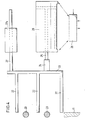
- the deflection device according to the invention can also be used in connection with the outlet star of a filling device, a labeling machine, etc. 11, the deflection devices are arranged so that the bottles can leave the spout when the deflection devices are retracted or switched off on the transport device 12, while the bottles with the deflection devices extended or switched on from the spout starter to a second transport device 14, a turntable, etc. . get picked up.
- FIG. 12 shows another possible combination of the deflection device according to the invention with a transport star.
- This arrangement is particularly advantageous under dynamic pressure.
- the main stream of objects is rotated in the direction by 90 ° by the deflecting surface 30 and sluiced onto a transport device.
- the objects to be deflected determined by an inspector, on the other hand, continue straight ahead.
- the control method described above is reversed. By changing the direction of the main flow of objects it is achieved that, for. B. the back pressure occurring in a production line remains without influence on the device and can be sorted out under full back pressure in the production line.
- a further possible application of the device is obtained if the friction between the object and the segment is increased by a friction lining which is applied to the contact surfaces of the segments. This allows the objects to be moved to another position when deflected. (Cylindrical objects, for example, roll off the deflection plane - cuboid-shaped ones make one or more quarter-turns about their axis if the flow switch is controlled accordingly.)
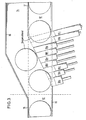
- a beverage filling system is described below, which is set up to fill different cylindrical bottle types (diameter 50-90 mm) in alternating operation; where the filled bottles are checked for closure and level and then a good-bad sort tion is executed. .
- the deflection section runs parallel to the first transport device 12 in the form of a steel link chain; on which the production line runs, a second transport device 14 at a distance of about. 5 to 10 mm, which is used to remove the deflected bottles.
- the fixed side railing 15 of the first transport device. 12 turns parallel to the deflection plane in the deflection section and becomes the outer railing 15 of the second transport device 14.
- the second railing 16 of the first transport device 12 consists of two superimposed ones.
- Guide rods 23 which can be displaced inwards and outwards perpendicular to the conveying direction in order to adapt to different bottle diameters.
- the two transport devices have a common fixed railing 17 immediately after the deflection section, by means of which mixing after the deflection is avoided
- the deflection device itself consists of 9 individually extendable segments 18, which are closely lined up. These segments each consist of 3 fingers 22, which are attached to a vertical bracket 20 in such a way that one just over the steel link chain, one between and. one can be extended over the two guide rods 23.
- the length of the fingers 22 is determined by the extension path; for example, in this embodiment the shortest finger (segment 18a) is approximately 30 mm and the longest finger (segment 18i) is approximately 115 mm long.
- the fingers 22 are chamfered on their front side in such a way that they form a smooth deflection plane in the extended state, which is approximately at an angle of 30 ° to the conveying direction.
- the first segment 18a has a slight curvature so that the. Bottles are guided in a smooth transition from the conveying direction to the deflection direction.
- the first segment 18a with a width of approximately 28 mm is somewhat wider than the remaining 8 segments, all of which have a width of 20 mm.
- the extension direction forms an angle of 105 ° with the conveyor.
- a guide rod 27 is fastened on the side opposite the fingers at the upper end, which is guided in plastic bushings 27a and thus gives the segment the necessary stabilization.
- the piston rod of the pneumatic cylinder 26 used as an actuator engages approximately in the middle of the bracket.
- the cylinder 26 is controlled by an electrically actuated 5/2-way valve as a control valve 28.
- All segments and actuators are mounted on a base plate that can be moved together with the railing guide rods.
- the control principle described above applies to the predecessor and successor of the object to be rejected.
- the test line about 15 cm in front of the first segment is represented in this version by a trigger light barrier, which FF 0 sets or does not set depending on the two test conditions level / closure.
- a 256 ⁇ 1 element CCD camera is used to determine the position of the predecessor and the successor of a bottle to be rejected.
- the version described here is suitable for cylindrical bottles with a diameter of 56 mm and has an output of up to 50,000 bottles per hour (belt speed approx. 1.5 m / sec).
- the structure of the transport device is the same as that in Example 1, except that the railing 16 is interrupted in the deflection section.
- the deflection device in turn consists of 9 individually extendable segments which are lined up closely together.
- the segments each consist of a vertical, 100 mm high and about 20 mm wide (the first segment has a width of 25 rnm) plastic hill with 4 ridges (sliding tabs), along which the bottles slide.
- the segments are extended and retracted by double-acting cylinders (16 mm piston diameter) with a continuous piston rod; these cylinders are controlled via electrically operated 5/2 way valves with quick exhaust.
- the piston rods each carry two 30 mm long springs.
- a guide rod is attached to the segments above the cylinders and is connected to the piston rod on the other side by a yoke.
- the cylinders sit in a carrier block made of plastic, which is also a slide bearing for the guide rods.
- control principle described above is applied to the predecessor and successor of the object to be rejected, implemented in a microprocessor program.
- a test line 32 (trigger light barrier) about 15 cm in front of the first deflection device determines whether the two test conditions fill level and closure are met or not.
- the air nozzle control device working with a microprocessor "remembers" the defective bottle, ie. H. the position on the transport device (link chain) where it is located.
- This multiple inductive sensor (Fig. 15) consists of 6 individual inductive proximity switches, which are mounted close to the link chain with 44.3 mm center distances.
- the hinges of the link chain which slide over the initiators at 38.1 mm centers, then generate the desired clock pulses.
- the control "knows" exactly when the defective bottle is in front of segment a, b, c, etc.
- the transport speed is calculated from the clock pulses of the inductive scanner and the valves in question are activated earlier (fast) or later (slowly) depending on the transport speed.
- the microprocessor control system follows the course of the bottles that cannot be rejected or their position on the link chain.
- the control unit can always extend the maximum possible number of railing segments between two error-free bottles in the event of an error message from the test facility.
- the control must also take into account the operating times of the individual segments, since the transport speed varies constantly (0 to 1.5m / sec.).
- the microprocessor In accordance with the respective transport speed, which is automatically calculated from the time interval between the clock pulses, the microprocessor repeatedly calculates the necessary advance of its control points (retraction-extension) for each individual cylinder and takes them into account in the control.
Landscapes
- Engineering & Computer Science (AREA)
- Mechanical Engineering (AREA)
- Branching, Merging, And Special Transfer Between Conveyors (AREA)
- Control Of Conveyors (AREA)
- Special Conveying (AREA)
- Sorting Of Articles (AREA)
- Attitude Control For Articles On Conveyors (AREA)
- Discharge Of Articles From Conveyors (AREA)
Description
Die Erfindung betrifft eine Vorrichtung zum seittichen Ablenken von bestimmten, nach einem Merkmal ausgewählten Gegenständen von einer ersten, durch ein Transportband gebildeten Transporteinrichtung auf eine zweite Transporteinrichtung der abgelenkten Gegenstände. Derartige Vorrichtungen sind zum Beispiel in Anlagen enthalten, die Flüssigkeiten in Behälter, wie Flaschen, abfüllen und dienen dazu, fehlerhafte Behälter, zum Beispiel nicht vollständig gefüllte oder nicht ordnungsgemäß verschlossene Flaschen auszusondern, die nicht für den Verkauf geeignet sind.The invention relates to a device for the lateral deflection of certain objects selected according to a feature from a first transport device formed by a conveyor belt to a second transport device of the deflected objects. Devices of this type are contained, for example, in systems which fill liquids into containers such as bottles and are used to separate out defective containers, for example bottles which are not completely filled or are not properly closed, and which are not suitable for sale.
Eine Vorrichtung nach dem Oberbegriff des Anspruches 1 ist aus der DE-A-2 437 798 bekannt. Die Ablenkeinrichtung besteht dabei aus einem keilförmigen Auswerfer, der die ausgewählten Gegenstände auf die zweite Transporteinrichtung abschiebt oder ablenkt. Insbesondere bei Getränkeflaschen, die keine hohe Standfestigkeit besitzen und leicht umkippen, ist die bekannte Ablenkvorrichtung in ihrer Arbeitsgeschwindigkeit beschränkt. Dies ergibt sich insbesondere daraus, daß die Länge des Keils in Förderrichtung nicht wesentlich größer sein darf, als der Durchmesser der Flaschen, da sonst dicht aufeinanderfolgende Flaschen nicht mehr selektiv abgelenkt bzw< durchgelassen werden können. Eine kurze Länge des Keils ist jedoch nur möglich, wenn die Flaschen unter einem reiativ großen Winkel abgelenkt werden, was jedoch wiederum nur bei relativ geringen Geschwindigkeiten der Transporteinrichtungen möglich ist. Eine Ablenkvorrichtung mit mitlaufenden Ablenksegmenten ist aus der US-A-3361 247 bekannt, wobei die erste Transporteinrichtung aus einem Gliederband besteht, bei dem jedes Glied mit einem querverschiebbaren Ablenksegment verbunden ist, und eine Mehrzahl von Ablenksegmenten zusammen die unter einem Winkel zur ersten Transporteinrichtung liegende Ablenkfläche bildet. Nachteilig ist hierbei, daß sich die einzelnen Ablenksegmente gerade zu dem Zeitpunkt in Bewegung befinden, wenn ein abzulenkender Gegenstand auf sie trifft. Gegenstände mit geringer Standfestigkeit, zum Beispiel Flaschen, werden dabei leicht umgestoßen. Die bekannte Ablenkvorrichtung erfordert außerdem einen sehr großen mechanischen Aufwand, da das gesamte Gliederband mit Ablenksegmenten ausgerüstet werden muß.A device according to the preamble of claim 1 is known from DE-A-2 437 798. The deflection device consists of a wedge-shaped ejector that pushes or deflects the selected objects onto the second transport device. Particularly in the case of beverage bottles that do not have a high level of stability and tip over easily, the known deflection device is limited in its working speed. This results in particular from the fact that the length of the wedge in the conveying direction must not be significantly greater than the diameter of the bottles, since otherwise closely spaced bottles can no longer be selectively deflected or let through. However, a short length of the wedge is only possible if the bottles are deflected at a relatively large angle, which in turn is only possible at relatively low speeds of the transport devices. A deflection device with moving deflection segments is known from US-A-3361 247, the first transport device consisting of a link belt, in which each link is connected to a displaceable deflection segment, and a plurality of deflection segments together which are at an angle to the first transport device Deflection surface forms. The disadvantage here is that the individual deflection segments are in motion at the time when an object to be deflected hits them. Objects with low stability, such as bottles, are easily knocked over. The known deflection device also requires a very large mechanical effort, since the entire link belt must be equipped with deflection segments.
Aus der DE-A-2 358 185 ist ebenfalls eine Ablenkvorrichtung bekannt, bei der die Gegenstände, zum Beispiel die Flaschen, durch mit der ersten Transporteinrichtung mitlaufende Ablenksegmente auf die zweite Transporteinrichtung verschoben werden. Die Ablenksegmente werden durch eine Weiche auf eine Führungsbahn geleitet, durch die sie quer zur Förderrichtung verschoben werden. Um bei dieser bekannten Vorrichtung zu verhindern, daß die auszusondernden Gegenstände von den Ablenksegmenten abgleiten, muß deren Breite etwa dem Durchmesser der Gegenstände entsprechen. Die auszusondernden Gegenstände dürfen außerdem nicht in dichter Folge ankommen, sondern müssen durch eine geeignete Einrichtung vereinzelt werden, d. h. der Abstand zwischen den Gegenständen muß eine gewisse Mindestgröße besitzen. Die bekannte Vorrichtung bes'tzt daher zwangsläufig eine relativ große' Abmessung, wodurch zum Beispiel das Ausleiten der Gegenstände auf sogenannte Drehteller erschwert wird.A deflection device is also known from DE-A-2 358 185, in which the objects, for example the bottles, are displaced onto the second transport device by deflecting segments which move with the first transport device. The deflection segments are guided through a switch to a guide track, through which they are moved transversely to the conveying direction. In order to prevent the objects to be separated from sliding off the deflection segments in this known device, their width must correspond approximately to the diameter of the objects. The items to be separated out must also not arrive in close succession, but must be separated by a suitable facility, i. H. the distance between the objects must have a certain minimum size. The known device therefore inevitably has a relatively large dimension, which, for example, makes it difficult to discharge the objects onto so-called turntables.
Aus der DE-A-2 555 192 ist eine Vorrichtung zum Ablenken von Gegenständen bekannt, wobei die Transporteinrichtung aus einzelnen schmalen Riemen besteht, die über Walzen laufen. Die Gegenstände werden durch einen Kamm abgelenkt, der von unten zwischen den Riemen nach oben geschoben wird. Diese Vorrichtung ist nur in Fällen anwendbar, in denen der Abstand zwischen den einzelnen Gegenständen relativ groß ist.A device for deflecting objects is known from DE-A-2 555 192, the transport device consisting of individual narrow belts which run over rollers. The objects are deflected by a comb, which is pushed upwards between the belts. This device is only applicable in cases where the distance between the individual objects is relatively large.
Die US-A-3 512 638 beschreibt eine Ablenkvorrichtung, insbesondere für Pakete und ähnliche Behälter. Die Transporteinrichtungen bestehen dabei aus Walzenbahnen, wobei die erste Walzenbahn im Ablenkbereich eine Kurve beschreibt. Die Ablenksegmente werden durch senkrecht zwischen zwei Walzen ausfahrbaren Ablenkrollen gebildet. Um ein Hängenbleiben der Pakete oder sonstigen Gegenstände an den Abrollen zu verhindern, müssen die Walzen der Transportbahn verdickte Bereiche aufweisen und müssen bestimmte dieser Walzen einen reibungserhöhten Belag besitzen. Die einzelnen Ablenkrollen werden durch gesonderte Lichtschranken gesteuert. Nachteilig ist hierbei, daß diese Ablenkvorrichtung nur bei Walzenbahnen anwendbar ist, nicht jedoch bei Transporteinrichtungen mit geschlossener Oberfläche, wie Gliederbänder oder Stahlbändern.US-A-3 512 638 describes a deflection device, particularly for packages and similar containers. The transport devices consist of roller tracks, the first roller track describing a curve in the deflection area. The deflecting segments are formed by deflecting rollers which can be extended vertically between two rollers. In order to prevent the packages or other objects from getting caught on the unrolling, the rollers of the transport path must have thickened areas and certain of these rollers must have a friction-increased coating. The individual deflection rollers are controlled by separate light barriers. The disadvantage here is that this deflection device can only be used with roller tracks, but not with transport devices with a closed surface, such as link belts or steel belts.
In der Veröffentlichung »Verzweigungen in horizontalen Förderstrecken«, in »Fördern und Heben«, Band 21,1971, Seiten 232-236 wird eine Ablenkvorrichtung mit Rollenbahnen als Transporteinrichtung beschrieben. Die Ablenkung der ausgewählten Gegenstände erfolgt durch Schwenken der Rollen.A deflection device with roller conveyors as a transport device is described in the publication "Branches in Horizontal Conveyor Lines", in "Conveying and Lifting", Volume 21, 1971, pages 232-236. The selected objects are deflected by swiveling the rollers.
Eine Anpassung an Fördereinrichtungen mit geschlossener Oberfläche ist nicht möglich.Adaptation to conveyor systems with a closed surface is not possible.
Die Erfindung, wie sie in den Ansprüchen gekennzeichnet ist, löst die Aufgabe, eine Vorrichtung zum seitlichen Ablenken von bestimmten, nach einem Merkmal ausgewählten Gegenständen von einer ersten Transporteinrichtung auf eine zweite Transporteinrichtung zu schaffen, die eine sehr hohe Arbeitsgeschwindigkeit besitzt und an den Transporteinrichtungen selbst keine speziellen Ausrüstungen erfordert.The invention, as characterized in the claims, achieves the object of providing a device for the lateral deflection of certain objects selected by a feature from a first transport device to a second transport device, which has a very high working speed and on the transport devices themselves no special equipment required.
Ausführungsbeispiele der Erfindung werden nachfolgend anhand der Zeichnung erläutert. Es zeigt
- Fig. 1 in Draufsicht eine Vorrichtung mit mechanisch arbeitenden geradlinig ausfahrbaren Segmenten;
- Fig. 2 die Steuerungslogik für eine Vorrichtung nach Fig. 1;
- Fig. 3 in Draufsicht eine Vorrichtung ähnlich Fig. 1 mit unter einem Winkel ausfahrbaren Segmenten;
- Fig.4 ein Segment im Querschnitt und mit Blickrichtung in Förderrichtung;
- Fig. 5 in Draufsicht eine Vorrichtung mit um eine Achse verschwenkbaren Segmenten;
- Fig. 6 in einer perspektivischen Darstellung ein Segment der in Fig. 5 gezeigten Ausführungsform;
- Fig.7, 8 und 9 Möglichkeiten für den Verlauf von Lichtschranken bei dicht aufeinanderfolgenden Gegenständen;
- Fig. 10 in Seitenansicht die Anordnung der Segmente der Vorrichtung von Fig. 5 und 6;
- Fig. 11 die Anwendung der Vorrichtung in Verbindung mit einem Auslaufstern;
- Fig. 12 die Anwendung einer Vorrichtung als Eckstation;
- Fig. 13 und 14 eine Ausführungsform, bei der das Aus- und Einfahren der Segmente durch Druckfedern unterstützt wird und
- Fig. 15 einen Vielfach-Induktivabtaster zur Erzeugung der für die Steuerung der Ablenkeinrichtung benötigten Taktimpulse.
- Figure 1 is a plan view of a device with mechanically operating straight extendable segments.
- FIG. 2 shows the control logic for a device according to FIG. 1;
- 3 shows a top view of a device similar to FIG. 1 with segments which can be extended at an angle;
- 4 shows a segment in cross section and looking in the conveying direction;
- 5 shows a top view of a device with segments pivotable about an axis;
- FIG. 6 shows a perspective illustration of a segment of the embodiment shown in FIG. 5;
- Fig. 7, 8 and 9 options for the course of light barriers in close successive objects;
- 10 shows a side view of the arrangement of the segments of the device from FIGS. 5 and 6;
- 11 shows the use of the device in connection with an outlet star;
- 12 shows the use of a device as a corner station;
- 13 and 14 an embodiment in which the extension and retraction of the segments is supported by compression springs and
- 15 shows a multiple inductive scanner for generating the clock pulses required for controlling the deflection device.
Die in Fig. 1 gezeigte Ablenkvorrichtung besitzt eine erste Transporteinrichtung 12 und eine zweite Transporteinrichtung 14, die z. B. aus einer Stahl- oder Kunststoft-Gliederkette bestehen können. Die Transporteinrichtungen sind seitlich durch Geländer 15, 16 und 17 begrenzt. Die zweite Transporteinrichtung verläuft parailel und unmittelbar benachbart zur ersten Transporteinrichtung. In einem bestimmten Bereich, der sogenannten Ablenkstrecke, sind die Geländer unterbrochen bzw. abgewinkelt, um ein Überleiten von Gegenständen von der ersten Transporteinrichtung auf die zweite Transporteinrichtung zu ermöglichen. In Fig. 1 sind drei Gegenstände dargestellt, von denen der mitτlere ausgesondert, d. h. abgelenkt oder ausgeleitet werden soll, während der erste und dritte Gegenstand auf der ersten Transporteinrichtung weiter befördert werden sollen. Der mittlere Gegenstand wird von der zweiten Transporteinrichtung weiter befördert. Das Ablenken eines ausgewählten Gegenstandes erfolgt durch Seg. mente 18n (n steht für a, b, c ...). Die Segmente sind in Fördereinrichtung der Transporteinrichtungen fest angeordnet und können etwa senkrecht zu dieser Förderrichtung ausgefahren werden.The deflection device shown in Fig. 1 has a
Da die auszuleitenden Gegenstände im allgemeinen durch die Ablenkfläche in Förderrichtung geringfügig abgebremst werden, und sich so der Abstand zum vorausgehenden Gegenstand, der nicht ausgeleitet wird, vergrößert bzw. sich der Abstand zu dem nachfolgenden Gegenstand verkleinert, erfölgt das Ausfahren der Segmente vorzugsweise etwa in Richtung der Winkelhalbierenden des von der Ablenkfläche 30 und der ersten Transporteinrichtung 12 gebildeten stumpfen Winkels.Since the objects to be rejected are generally braked slightly by the deflecting surface in the conveying direction, and the distance to the preceding object that is not rejected increases or the distance to the following object decreases, the segments are preferably extended approximately in the direction the bisector of the obtuse angle formed by the
Die Segmente können aus einem senkrechten Bügel 20 und mehreren waagrechten Fingern 22 bestehen. Die Länge der waagrechten Finger 22 wird vorzugsweise von den Ausfahrwegen der einzelnen Segmente bestimmt, so daß das an der Ablenkstrecke unterbrochene Geländer 16 durch einen oder mehrere Leitstäbe 23 ersetzt werden kann, die die Gegenstände sauber führen, wenn die einzelnen Segmente eingefahren sind. Die Ablenkstrecke ist der durch das erste und letzte Segment begrenzte Bereich. Durch einen Schaft 24 ist jedes Segment 18 mit dem Kolben 25 eines pneumatischen Zylinders 26 verbunden. In Abhängigkeit von der Stellung eines Magnet-Steuerventils 28 wird das Segment ausgefahren oder eingefahren.The segments can consist of a
Im ausgefahrenen Zustand bilden die Angriffsflächen der Segmente, z. B. die Vorderkanten der Finger22, eine Ablenkfläche 30, durch die die ausgewählten Gegenstände auf die zweite Transporteinrichtung abgelenkt werden. Die Segmente sind unterschiedlich weit ausfahrbar und die Angriffsfläche der Segmente ist entge- . gen der Förderemrichtung abgeschrägt. Zum Ablenken eines Gegenstandes wird das Segment 18a so weit ausgefahren, daß seine Angriffsfläche mit dem Geländer 16 bündig ist, und dann werden die übrigen Segmente 18b bis 18h soweit ausgefahren, daß ihre Angriffsfläche jeweils bündig mit der Angriffsfläche des vorausgehenden Segmentes ist. Die ersten Segmente, z. 3. 18a bis 18c, besitzen vorzugsweise eine gekrümmte Angriffsfläche, so daß das Geländer 16 in einer glatten Kurve in die Ablenkfläche 30 übergeht. Durch den glatten Übergang des Geländers 16 in die Ablenkfläche 30 wird auch bei hohen Arbeitsgeschwindigkeiten ein stoßfreies Ablenken der ausgewählten Gegenstände ermög!icht.In the extended state, the attack surfaces of the segments, for. B. the front edges of the
Die Ereite der Segmente 18n hängt von der Abmessung der Gegenstände in Förderrichtung und dem Abstand der Gegenstände voneinander ab. Die Breite der Segmente ist vorzugsweise kleiner als etwa die Hälfte oder etwa ein Drittel des Abstandes der Vorderkanten aufeinanderfolgender Gegenstände. Folgen die Gegenstände unmittelbar aufeinander, so soll die Breite der einzelnen Segmente nicht größer sein als etwa die Hälfte der.Abmessung der Gegenstände in Förderrichtung. Vorzugsweise soll die Segmentbreite kleiner : als etwa ein Drittel dieser Abmessung sein. Die Segmente müssen nicht gleiche Breite- haben und die ersten Segmente können z. B. eine etwas größere Breite besitzen. Die Anzahl der Segmente hängt von der Größe der Gegenstände und der Fördergeschwindigkeit ab.The length of the segments 18n depends on the dimension of the objects in the conveying direction and the distance of the objects from one another. The width of the segments is preferably less than about half or about a third of the distance between the leading edges of successive objects. If the objects follow each other immediately, the width of the individual segments should not be greater than about half the dimension of the objects in the conveying direction. The segment width should preferably be smaller than about a third of this dimension. The segments do not have to have the same width and the first segments can e.g. B. have a slightly larger width. The number of segments depends on the size of the objects and the conveying speed.
Bei der in den Figuren 1, 3 und 4 dargestellten Ausführungsform werden die Segmente in der Ebene der Transporteinrichtungen und senkrecht zur Förderrichtung bewegt. Es ist jedoch auch möglich, die Segmente vertikal von oben einzufahren. Je nach Art der Gegenstände können die Segmente einzelne Finger 22 aufweisen oder kann die Angriffsfläche der Segmente durch eine geschlossene Metall- oder Kunststoffläche gebildet werden. Den Winkel, den die Ablenkflächen 30 mit der Förderrichtung der ersten Transporteinrichtung 12 bildet, hängt von der Fördergeschwindigkeit ab und ist um so kleiner, je höher die Fördergeschwindigkeit ist.In the embodiment shown in FIGS. 1, 3 and 4, the segments are moved in the plane of the transport devices and perpendicular to the conveying direction. However, it is also possible to retract the segments vertically from above. Depending on the type of objects, the segments can have
Durch feine Luftdüsen in der Angriffsfläche der Segmente kann ein Luftkissen zwischen den Gegenständen und den Segmenten gebildet werden. Durch ein derartiges Luftkissen kann die Reibung zwischen den Gegenständen und den Angriffsflächen der Segmente verringert werden und ein abzulenkender Gegenstand in Ablenkrichtung sogar noch beschleunigt werden. Durch derartige Luftkissen wird auch das teilweise Überholen eines abgelenkten Gegenstandes durch einen nachfolgenden Gegenstand vermieden, da der abgelenkte Gegenstand nicht abgebremst wird.An air cushion between the objects and the segments can be formed by fine air nozzles in the surface of the segments. Such an air cushion can reduce the friction between the objects and the contact surfaces of the segments and even accelerate an object to be deflected in the deflection direction. Air cushions of this type also avoid the partial overtaking of a deflected object by a subsequent object, since the deflected object is not braked.
In Fig. 1 ist nur eine Reihe von Segmenten gezeigt, die sich an dem in der Figur unteren Rand der ersten Transporteinrichtung befinden. Zur Verbesserung der Führung-der Gegenstände kann das schrägverlaufende Geländer 15 ebenfalls durch eine Reihe von Segmenten ersetzt werden, deren Angriffsflächen parallel zur Förderrichtung der ersten Transporteinrichtung verlaufen und die so gesteuert werden, daß sie einen festen Abstand, der der Breite der ersten Transporteinrichtung entspricht, von den Segmenten 18n besitzen. Die weiteren Segmente können unter Einhaltung dieses Abstandes fest mit den Segmenten 18n verbunden sein. Wenn in der ersten Transporteinrichtung abstromseitig der Ablenkvorrichtung ein Stau auftritt, ist eine derartige Reihe von zweiten Segmenten besonders vorteilhaft, da sie ein nicht beabsichtigtes Ausweichen der Gegenstände auf die zweite Transporteinrichtung verhindern.In Fig. 1 only a number of segments are shown, which are located on the lower edge of the first transport device in the figure. To improve the guidance of the objects, the
Bei der vorausgehend beschriebenen Ausführung stellt das Ausfahren der Segmente eme reine Translationsbewegung dar.In the embodiment described above, the extension of the segments represents a pure translational movement.
In einer alternativen Ausführung beruht das Ausfahren der Segmente auf einer Rotationsbewegung (Fig.5, 6 und 10). Hierbei sind die Segmente 58n einzeln drehbar an einer senkrecht, etwa in Höhe des- ersten Segments 58a, direkt neben der ersten Transperteinrichtung stehenden Achse 51 aufgeharrgen. Jedes Segment wird durch einen Pneumatikzylinder oder durch einen Elektromagneten 55, der, um die Hebelwirkung auszunutzen, nahe der Drehachse angreift, ausgefahrerr. Die Segmente selbst bestehen aus vorzugsweise zwei Winkeln 57, die jeweils einen konzentrisch zu dem Drehpunkt gebogenen Schenkel 52 besitzen. Diese gebogenen Schenkel der beiden Winkel enden an-einem senkrechten Bügel 56, der auf der gegenüberliegenden Seite eine oder mehrerr Erhöhunger besitzt (Gleitnasen 59), an denen die Gegenstände entlanggleiten können. Bügel und Gleitnasen bilden mit dem Radiusvektor zur Segmentspitze einen spitzen Winkel derart, daß sich bei eingefahrenen Segmenten in Förderrichtung eine glatte Ebene ergibt, die dann zwangsläufig durch Herausschwenken der einzelnen Segmente in eine glatte Ablenkebene mit beliebigem Winkel zur Förderrichtung übergeht.In an alternative embodiment, the segments are extended based on a rotational movement (FIGS. 5, 6 and 10). In this case, the segments 58n are individually rotatable on an
Mit den geraden Schenkeln 53 der beiden Winkel sind die Segmente, wie oben erwähnt, frei drehbar an einer feststehenden Achse 51 . aufgehangen.With the
Als weitere Alternative ist natürlich auch eine neben der ersten Transporteinrichtung waagrecht liegende Drehachse als Aufhängung für die Geländersegmente möglich. Diese Drehachse kann sich sowohl in der durch die Oberfläche der Transporteinrichtungen gegebenen Ebene als auch oberhalb oder unterhalb dieser Ebene befinden; die Richtung der Drehachse kann parallel zur Förderrichtung oder zur Ablenkfläche liegen oder auch einen Zwischenwert annehmen;As a further alternative, of course, an axis of rotation lying horizontally next to the first transport device is also possible as a suspension for the railing segments. This axis of rotation can be located both in the plane given by the surface of the transport devices and above or below this plane; the direction of the axis of rotation can be parallel to the conveying direction or to the deflection surface or can also assume an intermediate value;
Der Grundgedanke der Erfindung besteht nun darin, nicht alle Segmente gleichzeitig aus- und einzufahren, sondern zu jedem Zeitpunkt nur diejenigen Segmente auszufahren, die zu diesem Zeitpunkt oder unmittelbar danach zum Ablenken des Gegenstandes tatsächlich benötigt werden, d. h. diesen Gegenstand berühren: Ein Ablenken ist dadurch auch in Fällen möglich, in denen die Gegenstände unmittelbar aufeinanderfolgen, d. h. zwischen ihnen kein Abstand vorhanden ist, ohne daß die Gegenstände, die auf der ersten Transporteinrichtung verbleiben, beeinträchtigt werden. In Fig. 1 sind z. B. die Segmente 18a bis 18c,-die den in der Fig. 1 linken Gegenstand berühren würden, eingefahren und ebenso sind die Segmente 18g und 18h eingefahren, da sie den rechten Gegenstand berühren würden. Ausgefahren sind nur die Segmente 18e und 18f, da sie gerade an dem mittleren Gegenstand angreifen, der aussortiert werden soll. Das Segment 18b ist gerade teilweise eingefahren.The basic idea of the invention is now not to extend and retract all segments at the same time, but to extend only those segments at any point in time that are actually required at that point in time or immediately afterwards for deflecting the object, i. H. touch this object: a distraction is also possible in cases where the objects follow each other immediately, i.e. H. there is no distance between them without the objects remaining on the first transport device being impaired. In Fig. 1 z. B. the
Bei den vorausgehend beschriebenen Ausführungsformen befinden sich diejenigen Segmente im ausgefahrenerr Zustand, die zu dem betreffenden Zeitpunkt oder unmittelbar danach an dem ausgewählten Gegenstand angreifen. In einer bevorzugten Ausführungsform können sich zu jedem Zeitpunkt diejenigen Segmente im ausgefahrenen Zustand befinden, die mit dem unmittelbar vorausgehenden und dem unmittelbar nachfolgenden Gegenstand, die auf der ersten Transporteinrichtung verbleiben, nicht kollidieren. Dadurch befindet sich während eines Ablenkvorganges die maximale Anzahl von Segmenten im ausgefahrenen Zustand.In the embodiments described above, those segments are in the extended state which attack the selected object at the relevant time or immediately thereafter. In a preferred embodiment, those segments that do not collide with the immediately preceding and the immediately following object that remain on the first transport device can be in the extended state at any time. As a result, the maximum number of segments is in the extended state during a deflection process.
Zur Feststellung der Gegenstände, die abgelenkt werden müssen, werden bestimmte Merkmale des Gegenstandes, z. B. Füllstandshöhe in Flasshen oder das Vorhandensein eines Flaschenverschlusses beim Sortieren von Flaschen, mechanisch, z. B. durch eine Waage oder Abtastelemente, oder photoelektrisch, geprüft. Bei der in Fig. 1 gezeigten Ablenkvorrichtung findet die Prüfung an der Prüflinie 32 statt, die sich vorzugsweise unmittelbar vor der Ablenkstrecke befindet. Wenn die Prüfung zu einem früheren Zeitpunkt erfolgt, so muß sie durch geeignete Mittel, z. B. ein Schieberegister, zeitlich so verzögert oder gespeichert werden, daß das Prüfergebnis der Steuereinrichtung für die Segmente zu dem Zeitpunkt zugeführt wird, zu dem der betreffende Gegenstand in die Ablenkstrecke eintritt.To determine the objects that need to be distracted, certain features of the object, e.g. B. level in Flasshen or the presence of a bottle cap when sorting bottles, mechanically, for. B. checked by a balance or scanning elements, or photoelectrically. In the deflection device shown in FIG. 1, the test takes place on the
Die Einrichtung zum Steuern der Segmente weist im einfachsten Fall die vorausgehend erwähnten Prüfeinrichtungen, Lichtschranken 34a bis 34h zur Erzeugung eines Einfahrbefehles, Lichtschranken 35a bis 35h zur Freimeldung des jeweiligen Segmentes und eine Steuerelektronik (Fig. 2) auf. Bei der in Fig. 1 und 2 dargestellten Steuereinrichtung wird dabei diejenige Alternative gezeigt, bei der jeweils die maximale Anzahl von Segmenten ausgefahren ist, d. h. alle Segmente, die nicht mit dem unmittelbar vorausgehenden und dem unmittelbar nachfolgenden Gegenstand, die nicht abgelenkt werden sollen, kollidieren. Die Lichtschranke 35a gibt nach dem Durchgang des Gegenstandes, der dem abzulenkenden Gegenstand vorausgeht, eine Freimeldung ab. Die Freimeldung wird durch ein Zeitglied 40a um eine Zeitdauer t verzögert und auf den Setzeingang des Flip-Flops 1a gegeben. Der Betrag der Zeitverzögerung hängt von der Geschwindigkeit der ersten Transporteinrichtung, der Ansprechzeit der Steuereinrichtung und der Lage der Lichtschranke 35a ab. Die Freimeldung ist eine Voraussetzung für das Ausfahren eines Segmentes und die Zeitverzögerung soll so bemessen sein, daß derjenige Gegenstand, von dem die Freimeldung abgeleitet wird, von dem auf Grund der Freimeldung dann ausfahrenden Segment nicht mehr getroffen wird. Wie erwähnt, hängt die Zeitverzögerung dann von der Geschwindigkeit der Trensporteinrichtung ab. Da sich die Transportgeschwindigkeit während des Betriebes ändern kann, ist die durch das Zeitglied 40a eingeführte Verzögerung vorzugsweise variabel. Bei kleiner Transportgeschwindigkeit ist die Zeitverzögerung dabei größer als bei hoher Transportgeschwindigkeit. Das am normalen Ausgang des Flip-Flops 1a erhaltene Signal wird über ein UND-Glied 41a dem Setzeingang eines Flip-Flops 2a zugeführt. Der zweite Eingang des UND-Gliedes 41a ist mit dem normalen Ausgang eines Flip-Flops 0 verbunden, das von der Prüfeinrichtung gesetzt wird und sich g. B. im gesetzten Zustand befindet, wenn der Gegenstand, der dem Gegenstand folgt, von dem die Freimeldung abgeleitet wurde, aussortiert werden soll, da er z. B. fehlerhaft ist. Der normale Ausgang des Flip-Flops 2a steuert über einen Leistungstreiber ein Steuerventil 28, das z. B. einen pneumatischen Zylinder 26 betätigt, der das Segment 18a ausfährt. Das Segment 18a wird immer ausgefahren, wenn sich ein abzulenkender Gegenstand diesem Segment nähert und sich der unmittelbar vorausgehende Gegenstand bereits an diesem Segment vorbeibewegt hat, Die dem Segment 18b zugeordneten Steuerelektronik ist, abgesehen davon, daß der zweite Eingang des UND-Gliedes 41b nicht mit dem Flip-Flop 0, sondern mit dem normalen Ausgang des Flip-Flops 2a verbunden ist, identisch der dem Segment 18a zugeordneten Steuerelektronik. Das Segment 18b wird demnach ausgefahren, wenn eine Freimeldung der diesem Segment zugeordneten Lichtschranke vorliegt und wenn das Segment 18a ausgefahren ist. Die Steuerelektronik der weiteren Segmente ist analog der des Segments 18b. Ein beliebiges Segment wird demnach ausgefahren, wenn für dieses Segment eine Freimeldung vorliegt und das vorausgehende Segment ausgefahren ist.In the simplest case, the device for controlling the segments has the test devices mentioned above,
Durch weitere Lichtschranken 34n wird ein Einfahrbefehl von der Vorderkante jedes Gegenstandes abgeleitet. Jedem Segment 18n ist dabei neben einer Lichtschranke 35n für die Freimeldung auch eine Lichtschranke 34n für den Einfahrbefehl zugeordnet. Der Einfahrbefehl wird über Zeitglieder 44n verzögert. Die Lichtschranke 34n für den Einfahrbefehl eines Segmentes befindet sich dabei etwa eine Segmentbreite vor der Lichtschranke für die Freimeldung des betreffenden Segmentes, wenn Zeitglieder 40n und 44n mit gleicher Zeitverzögerung verwendet werden. Der Ausgang des Zeitgliedes 44a ist mit dem einen Eingang eines UND-Gliedes 42a verbunden. Der andere Eingang des UND-Gliedes 42a ist mit dem invertierten Ausgang des Flip-Flops 0 verbunden. Durch ein L-Ausgangssignal des UND-Gliedes 42a wird das Flip-Flop 1a und das Flip-Flop 2a rückgesetzt. Durch Rücksetzen des Flip-Flops 2a getangt ein 0-Signal zu dem Leistungstreiber des Segments 18a und wird dieses Segment dadurch eingefahren. Das Einfahren des Segments 18a erfolgt demnach, wenn ein Gegenstand die Einfahrbefehl-Lichtschranke 34 unterbricht und das Flip-Flop 0 rückgesetzt ist. Diese Bedingungen sind nach dem Ablenken eines Gegenstandes erstmals bei dem ersten nachfolgenden, nicht abzulenkenden Gegenstand erfüllt. Das UNC-Glied 42a hat eine doppelte Aufgabe, nämlich erstens wird durch es ein unnötiges Einfahren der Segmente verhindert, falls zwei aufeinanderfolgende Gegenstände abgelenkt werden sollen, und zweitens wird durch es verhindert, daß durch den Einfahrbefehl, der von einem abzulenkenden Gegenstand abgeleitet wird, ein Segment eingefahren wird, bevor sich dieser Gegenstand an diesem Segment vorbeibewegt hat.An entry command is derived from the front edge of each object by further light barriers 34n. In addition to a light barrier 35n for free signaling, a light barrier 34n for the entry command is also assigned to each segment 18n. The move-in command is delayed via timers 44n. The light barrier 34n for the entry command of a segment is located approximately one segment width in front of the light barrier for the free signaling of the relevant segment if timers 40n and 44n are used with the same time delay. The output of the timer 44a is connected to one input of an AND
Das Segment 18b wird eingefahren, wenn die betreffende Einfahrbefehl-Lichtschranke 34b durch einen Gegenstand unterbrochen wird und das vorausgehende Segment 18a eingefahren ist, d. h. das Flip-Flop 2a rückgesetzt ist. Die Segmente 18c bis 18h werden unter analogen Bedingungen eingefahren. In der Praxis arbeitet die Steuerungseinrichtung in der Weise, daß durch den letzten fehlerfreien Gegenstand z. B. die ersten fünf Segmente 18a bis 18e freigemeldet sind. Wenn dann von der Prüfeinrichtung ein fehlerhafter Gegenstand festgestellt wird, so wird das Flip-Flop 0 gesetzt und werden praktisch gleichzeitig die ersten fünf Segmente ausgefahren. Die Segmente 18f, 18g usw. werden erst dann ausgefahren, wenn sie ebenfalls freigemeldet sind, d. h. die ihnen zugeordnete Freigabebefehl-Lichtschranken 35f, 35g usw. nicht mehr durch den letzten fehlerfreien Gegenstand unterbrochen sind.The
Der Einfachheit halber ist bisher angenommen worden, daß sich die Lichtschranken 34a bis 34h und 35a bis 35h an den in Figur 1 entsprechend bezeichneten Linien befinden. Zum Beispiel bei Flaschen, die am Flaschenhals abgetastet werden, stellen die unterbrochenen Linien, die mit 34a bis 34h und mit 35a bis 35h bezeichnet sind, nicht die tatsächlichen Abtastlinien, d. h. die Position der Lichtschranken dar, sondern markieren sie die Stelle, an der sich die Vorderkante bzw. Hinterkante des steuernden Gegenstandes im Moment der Abtastung, d. h. der Erzeugung des Steuerimpulses befindet. Bei der tatsächlichen Lage der Lichtschranken ist die Fördergeschwindigkeit und die Ansprechzeit der Zylinder und Ventile sowie die Aus- bzw. Einfahrzeit der Segmente zu berücksichtigen. Die Lichtschranken müssen daher eine Distanz vor den zugeordneten Segmenten angeordnet werden, die sich im wesentlichen aus dem Produkt von Fördergeschwindigkeit und der Summe von Ansprechzeit und Aus- bzw. Einfahrzeit ergibt. Je Segment werden normalerweise eine Freimelde-Lichtschranke (Dunkel-Hell-Übergang) und eine Einfahrbefehl-Lichtschranke (Hell-Dunkel-Übergang) benötigt. Liegt die Ausfahrzeit von Segment n etwa in der gleichen Größenordnung wie die Einfahrzeit von Segment n+1, dann kann man die Freimelde-Lichtschranke von n und die Einfahrbefehl-Lichtschranke von n+1, wie in Fig. 1 gezeigt, zu einer einzigen Lichtschranke zusammenfassen, von deren Ausgangssignal' durch Differenzieren die dem Hell-Dunkel-Übergahg entsprechende Flanke zum Einfahrimpuls und die dem Dunkel-Hell- Übergang entsprechende FlankE zum Freimeldeimpuls wird.For the sake of simplicity, it has previously been assumed that the
Liegen alle Ein- und Ausfährzeiten in der gleichen Größenordnung, dann sind zudem die Abstände zwischen den Lichtschranken etwa gleich den Segmentbreiten (Fig. 1). Zum Beispiel benötigt ein Luftzylinder mit Rückstellfeder getrennte Einfahr- und Freimelde-Lichtschranken, während die wegen der höheren Stellgeschwindigkeit bevorzugt verwendeten doppeltwirkenden Luftzylinder mit einer Anordnung nach Fig. 1 auskommen.If all entry and exit times are of the same order of magnitude, then the distances between the light barriers are approximately equal to the segment widths (Fig. 1). For example, an air cylinder with a return spring requires separate entry and free signal light barriers, while the double-acting air cylinders, which are preferred because of the higher actuating speed, manage with an arrangement according to FIG. 1.
Es ist auch möglich, nicht für jedes Segment n getrennte Lichtschranken 34n und 35n vorzusehen, sondern insgesamt nur eine einzige Einfahrbefehl-Lichtschranke 34 und eine einzige Freimelde-Lichtschranke 35 am Eingang der Ablenkvorrichtung vorzusehen, z. B. an der Position der oben genannten Lichtschranke 35a und 34a. Die Freimeldungen und Einfahrbefehle für die Segmente 18b bis 18h werden dann dadurch erhalten, daß die von der einzigen Freimeldungs-Lichtschranke und der einzigen Einfahrbefehl-Lichtschranke abgeleiteten Signale entsprechend der Fördergeschwindigkeit der ersten Transporteinrichtung und dem Abstand der Segmente zeitlich verzögert werden.It is also possible not to provide n separate light barriers 34n and 35n for each segment, but to provide only a single entry command light barrier 34 and a single clear signal light barrier 35 at the entrance of the deflection device, e.g. B. at the position of the above-mentioned
Um Fehlfunktionen auszuschließen, muß die Lage der Abtastsysteme so gewählt werden, daß . bei vorgegebener Form und vorgegebenem Abstand der Gegenstände die einzelnen Gegenstände sicher voneinander unterschieden (aufgelöst) werden können und die Triggerimpulse (Freimeldungen, Einfahrbefehle) mit einer bestimmten, im wesentlichen von der Geschwindigkeit der Gegenstände abhängigen Genauigkeit reproduziert werden können.To rule out malfunctions, the position of the scanning systems must be selected so that. given shape and distance of the objects, the individual objects can be safely distinguished from each other (resolved) and the trigger impulses (free messages, entry commands) can be reproduced with a certain accuracy, which essentially depends on the speed of the objects.
Bei größeren Abständen (so groß, daß der Nachfolger eines abzulenkenden Gegenstandes diesen während des Ausleitprozesses nicht überholt) können Lichtschranken, die in Ausfahrrichtung der Segmente strahlen, sicher die geforderten Triggerimpulse (Freimeldung bzw. Einfahrbefehl) liefern. Hierbei ist es unerheblich, daß bei dem Prinzip der Steuerung auf Vorgänger und Nachfolger der auszuleitende Gegenstand selbst auch Triggerimpulse liefert, da diese Impulse durch die in Fig. 2 angegebene Schaltung unterdrückt werden. Bei kleineren Abständen zwischen den Gegenständen bestimmt allein deren Form die Lage und Richtung der Lichtschranken.In the case of larger distances (so large that the successor of an object to be deflected does not overtake it during the rejection process), light barriers that radiate in the direction of extension of the segments can reliably provide the required trigger impulses (free signal or entry command). It is irrelevant here that, in the case of the principle of control on predecessor and successor, the object to be discharged itself also supplies trigger pulses, since these pulses are suppressed by the circuit shown in FIG. 2. With smaller distances between the objects, their shape alone determines the position and direction of the light barriers.
So wird man z. B. Flaschen in Halshöhe abtasten, wobei die Richtung der Lichtschranken etwa der der Winkelhalbierenden des von Ablenkebene und erster Transporteinrichtung gebildeten stumpfen Winkels entspricht. Durch schräg nach oben oder unten verlaufende Lichtschranken (Fig. 7) können Gegenstände abgetastet werden, die zusammen keine kontinuierliche in Förderrichtung verlaufende Kante 36 bilden, z. B. zylindrische Gegenstände wie Konservendosen. Gegenstände, die zusammen keine kontinuierliche geschlossene Oberfläche bilden, können mit geeigneten Reflexlichtschranken von oben von der Ausleitseite abgetastet werden (Fig. 8).So you will z. B. scan bottles at neck height, the direction of the light barriers corresponds approximately to that of the bisector of the obtuse angle formed by the deflection plane and the first transport device. Objects which do not together form a
Durch das Prinzip der Steuerung auf Vorgänger und Nachfolger wird eine besonders günstige in Fig. 9 dargestellte Lichtschrankenanordnung ermöglicht. Die Lichtschrankensender 93b bis 93h und 94a bis 94g sind hierbei in die Finger 22 integriert. Die Sender können z. B. Infrarot-Leuchtdioden sein, können aber auch Lichtleiter sein, die zu feststehenden Lichtschrankeneinheiten führen.The principle of control on predecessor and successor enables a particularly favorable light barrier arrangement shown in FIG. 9. The
Die Strahlrichtungen der Lichtschrankensender 93b bis 93h, die die Einfahrbefehle liefern, verlaufen von den Sendern in den einzelnen Segmenten vorzugsweise parallel zur Ablenkfläche zu einem ersten Lichtschrankenempfängerblock 91. Die Strahlrichtungen der Freimelde-Lichtschranken verlaufen von Sendern 94a bis 94g in den Segmenten zu einem zweiten Lichtschrankenempfängerblock 92. Die Zuordnung der Lichtschranken ist so gewählt, daß jedes der Segmente 18b bis 18h hei einem herannahenden nicht auszuleitenden Gegenstand durch das Signal seiner Einfahr-Lichtschranke eingefahren wird und jedes der Segmente 18a bis 18g bei einem auszuleitenden Gegenstand das nächste Segment abhängig von dem vorangehenden Gegenstand freigemeldet bzw. ausgefahren wird.The beam directions of the
Das erste Segment 18a wird in diesem Fall durch die Prüflichtschranke- (Prüflinie 32) gesteuert. Die Position von Sender und Empfänger kann auch vertauscht-sein, so daß die Blöcke 91 und 92 Sender sind und sich die Empfänger in den Segmenten befinden.In this case, the
Der Lauf der einzelnen Gegenstände kann außerdem durch induktive oder kapazitive Näherungsschalter, Ultraschall-, Luftschranken etc. oder mit Video-(CCD)-Kameras verfolgt werden. Solche Kamerasysteme werden nicht nur bei schwierig aufzulösenden Gegenständen eingesetzt, sondern auch bei Ablenkvorrichtungen, die verschiedene Ausführungsformen bestimmter Gegenstände in wechselndem Betrieb bearbeiten müssen (z. B. Füllstands- und Verschlußkontrolle bei auf mehreren Flaschensorten einstellbaren Getränkeabfüllanlagen).The course of the individual objects can also be followed by inductive or capacitive proximity switches, ultrasonic, air barriers etc. or with video (CCD) cameras. Such camera systems are not only used for objects that are difficult to resolve, but also for deflection devices that have to process different embodiments of certain objects in alternating operation (e.g. fill level and closure control in beverage filling systems that can be set on several types of bottles).
Die Vorteile der vorausgehend beschriebenen Steuerungsverfahren bestehen darin, daß die Segmente zum frühesten mögtichen Termin ausgefahren werden und zu dem Zeitpunkt, zu dem der abzulenkende Gegenstand auf ein Segment trifft, nicht mehr in Bewegung sind. Es wird dadurch verhindert, daß die Gegenstände durch die sich bewegende Segmente umgestoßen werden. Dadurch, daß erst ein nachfolgender Gegenstand den Befehl zum Einfahren der Segmente gibt, wird erreicht, daß einerseits bei größeren Abständen der Gegenstände ein Gegenstand durch die von den Segmenten gebildete Ablenkfläche ausgeleitet wird und andererseits bei kleinen Abständen der Gegenstände und dichter Folge mit Sicherheit auch die letzten Segmente so eingefahren werden, daß sie den Transport der Gegenstände nicht behindern. Da die Fördergeschwindigkeit eines Gegenstandes während des Ablenkens verringert werden kann, ist es dabei möglich, daß die letzten Segmente bereits eingefahren werden, bevor der Gegenstand vollständig auf die zweite Transporteinrichtung ausgeleitet ist, da der nachfolgende Gegenstand den ausgeleiteten Gegenstand zu überholen beginnt, und daher der Einfahrbefehl von dem überholenden Gegenstand scheinber zu früh gegeben wird. Der nachfolgende, überholende Gegenstand übernimmt dab.ei jedoch zwangsläufig eine Stützfunktion und schiebt seinen Vorgänger gänzlich von der ersten Transpor teinrichtung, auf die zweite Transporteinrichtung.The advantages of the control methods described above are that the segments are extended at the earliest possible date and are no longer in motion when the object to be deflected hits a segment. This prevents the objects from being knocked over by the moving segments. The fact that only a subsequent object gives the command to retract the segments ensures that, on the one hand, an object is diverted through the deflecting surface formed by the segments when the distances between the objects are greater, and on the other hand with certainty when the distances between the objects are small and the sequence is close last segments are retracted so that they do not hinder the transport of the objects. Since the conveying speed of an object can be reduced during the deflection, it is possible that the last segments are already retracted before the object is completely diverted to the second transport device, since the subsequent object begins to overtake the diverted object, and therefore the Entry command from the overtaking object is apparently given too early. However, the following, overtaking object inevitably takes on a supporting function and pushes its predecessor entirely from the first transport device onto the second transport device.
Ein weiterer Vorteil besteht darin, daß bei mehreren Gegenständen, die nacheinander abgelenkt werden, ungeachtet der Abstände dieser Gegenstände, die Segmente nur einmal ausgefahren und bei dem nächstfolgenden Gegenstand, der nicht ausgeleitet werden soll, da er z. B. fehlerfrei ist, wieder eingefahren werden. Würden die Freimeldung und der Einfahrbefehl von einem Gegenstand selbst, statt von dem vorausgehenden und dem nachfolgenden Gegenstand abgeleitet, so würden in dem vorausgehend genannten Fall die Segmente für jeden einzelnen Gegenstand ausgefahren und wieder eingefahren.Another advantage is that in the case of several objects which are deflected one after the other, regardless of the distances between these objects, the segments are extended only once and the next object which is not to be rejected, since it is e.g. B. is error-free, retracted. If the clearance notification and the entry command were derived from an object itself instead of from the preceding and the following object, the segments for each individual object would be extended and retracted in the aforementioned case.
Die Unabhängigkeit der Steuerung von dem auszuleitenden Gegenstand selbst ist außerdem vorteilhaft, da die Steuerung auf die Weise von der Form und der Lage eines Gegenstandes unabhängig ist. Wird die Steuerung dagegen von .dem abzulenkenden Gegenstand selbst abgeleitet, so wird die Erfassung verschiedenartiger Gegenstände durch Lichtschranken schwierig oder unlösbar. Durch die Steuerung der Segmente in Abhängigkeit von dem vorausgehenden und dem nachfolgenden Gegenstand wird es zum Beispiel möglich, aus einer Reihe zylindrischer Flaschen Flaschen anderer Form. z. B. viereckige Flaschen, oder umgefallene Flaschen und sogar Flaschenböden und ailgemein zerbrochene Flaschen und Glasbruch auszusortieren. Mit bekannten Sortiergeräten ist dies nicht möglich.The independence of the control from the object to be rejected is also advantageous since the control is independent of the shape and position of an object. If, on the other hand, the control is derived from the object to be deflected itself, the detection of different types of objects by means of light barriers becomes difficult or impossible. For example, by controlling the segments depending on the preceding and following items, it becomes possible to make bottles of a different shape from a series of cylindrical bottles. e.g. B. to sort out square bottles, or overturned bottles and even bottle bottoms and generally broken bottles and broken glass. This is not possible with known sorting devices.
Die Arbeitsgeschwindigkeit der vorausgehend beschriebenen Ausführungsformen der erfindungsgemäßen Ablenkvorrichtung wird begrenzt durch die Trägheit der Steuerventile 28 und der pneumatischen Zylinder 26. Die Zeit, die benötigt wird von der Ansteuerung bis zum Erreichen der gewünschten Endstellung (eingefahren - ausgefahren) eines pneumatischen Zylinders, läßt sich im wesentlichen in drei Abschnitte untergliedern:
- 1. Schaltzeit des Steuerventils 28;
- 2: Zeit, in
der im Zylinder 26 der Losbrechdruck erreicht und derKolben 25 die Haftreibung überwunden hat, d. h. bis sich die Kolbenstange bewegt (Losbrechzeit); - 3. Zeit der Bewegung der Kolbenstange (Bewegungszeit).
- 1. switching time of the
control valve 28; - 2: time in which the breakaway pressure in the
cylinder 26 has reached and thepiston 25 has overcome the static friction, ie until the piston rod moves (breakaway time); - 3. Time of movement of the piston rod (movement time).
Während die Schaltzeit des Steuerventils relativ konstant ist, müssen die Losbrechzeit und die Bewegungszeit mit einem Sicherheitszuschlag belegt werden, denn ein Kolben, der nur hin und wieder betätigt wird, ist langsamer als einer, der kontinuierlich arbeitet und die Kolbendichtung beginnt in der Ruhelage nach einigen Sekunden im erstarrten Öl- und Fettfilm an den Zylinderwandungen zu kleben. Zum Anfahren der Kolbenstange ist also in den meisten Fällen eine wesentlich höhere Kraft (Druck auf Kolben) nötig als zu ihrer Weiterbeweung.While the switching time of the control valve is relatively constant, the breakaway time and the movement time must be assigned a safety margin, because a piston that is only actuated from time to time is slower than one that works continuously and the piston seal begins in the rest position after a few Stick in the solidified oil and grease film on the cylinder walls for seconds. In most cases, a much higher force (pressure on the piston) is required to start the piston rod than to move it further.
Eine wesentliche Verkürzung der Losbrechzeit, nämlich auf weniger als 50%, wird bei einem doppeltwirkenden Zylinder 26 erreicht, indem die zum Losbrechen der Kolbenstange benötigte Energie nicht mehr nur durch die beaufschlagte Druckluft (Losbrechdruck) aufgebracht wird, sondern von einer Feder 29 (Fig. 13 und 14), in der die benötigte Energie als potentielle Energie, die von dem vorangehenden Hub in anderer Richtung aufgebracht wurde, gespeichert ist.A substantial reduction in the breakaway time, namely to less than 50%, is achieved with a double-acting
Die Kolbenstange jedes doppeltwirkenden Zylinders 26 der Segmente trägt dazu auf jeder Zylinderseite eine Schraubendruckfeder. Die Federwege sind kurz im Verhältnis zur Hublänge des Kolbens, z. B. halb so lang, und ihre Kräfte sind so bemessen und Gegenlager in solchen Abständen vorn Kolben angeordnet, daß die Federn in den Endlagen zwischen etwa 2 und 15 mm (je nach Hublänge) zusammengedrückt werden, bis sich das Gleichgewicht der Kräfte einstellt. In Fig. 13 bilden das Joch 64 und der Bügel 20 die Gegenlager. Die Endlage des Kolbens ist also die Position, in der die Federkraft gleich der durch die Druckkraft erzeugten Kolbenkraft ist. Die Federn können auch Innerhalb des Zylinders angeordnet sein oder als Blattfedern ausgebildet sein.For this purpose, the piston rod of each double-acting
Im Normalfall kann man Federn mit einer konstanten Federrate benutzen. Wenn aber der Anteil der kinetischen Energie sehr hoch ist oder nur minimales Überschwingen in der Endlage gefordert wird, muß man Federn mit einer exponentiellen oder progressiven Kennlinie oder mehrere konzentrisch angeordnete Federn unterschiedlicher Federraten verwenden.Normally you can use springs with a constant spring rate. However, if the proportion of kinetic energy is very high or only minimal overshoot is required in the end position, springs with an exponential or progressive characteristic curve or several concentrically arranged springs with different spring rates must be used.
Bei dem oben aufgeführten Zylinder sei nun der eine Anschluß 61 mit Druckluft beaufschlagt, d. h. das Geländersegment ist ausgefahren (Fig. 13) und die linke Feder ist zusammengedrückt. Schaltet jetzt die Steuerelektronik das Steuerventil 28 um, so daß nach der Verzögerung durch die Schaltzeit des Steuerventils 28 der andere Anschluß 62 mit Druckluft beaufschlagt und der eine Anschluß 61 entlastet wird, dann wird sich die Kolbenstange sofort nach links bewegen, da die Kraft der gespannten Feder 29, die gleich der Kolbenkraft ist, alleine schon ausreicht, um die Haftreibung des Kolbens zu überwinden und die Luft in der gegenüberliegenden Zylinderkammer über das Schnellentlüftungsventil 63 und das Steuerventil 28 auszutreiben. Zu der Federkraft kommt noch die Kraft des sich aufbauenden Luftdruckes, so daß der Kolben auf den ersten Millimeter der Hubstrecke mit einer Kraft beschleunigt wird, die erheblich über der eigentlichen Stoßkraft des Zylinders liegt. Nach Verlassen des Federbereichs wird der Kolben normal durch die Kraft des Luftdruckes beschleunigt bis die gegenüberliegende Feder erreicht wird, die jetzt als Endlagendämpfung fungiert und damit die zum Rückhub nötige Energie speichert.In the cylinder listed above, one
Die Anbringung von Federn 29 hat neben der Verkürzung der Lesbrechzeit noch einen weiteren Vorteil:
- Bei zwei parallelen Zylindern 26 für ein einziges Segment; deren Kolbenstangen durch
ein Jaeh 64 verbunden sind (Fig. 14), treten normalerweise infolge unterschiedilcher Losbrechzeiten Gleichlaufprobleme auf, die zur Verkantung derKolben 25 und zur schnellen Zerstörung der Lagerungen der Kolbenstangen führen. Wird die Haftreibung jedoch durch Federn 29 überwunden, so sind die Losbrechzeiten der beiden durchdas Joch 64 verbundenen Kolben im wesentlichen gleich, so daß keine Verkantung entsteht. Es bleiben nur Gleichlaufprobleme, die durch verschiedene Reibungskoeffizienten der beiden Zylinder verursacht werden. Diese auftretenden Kräfte sind leicht überdas Joch 64und den Bügel 20 abzufangen.
- With two
parallel cylinders 26 for a single segment; whose piston rods are connected by a Jaeh 64 (Fig. 14), usually occur due to different breakaway times synchronism problems that lead to the tilting of thepistons 25 and the rapid destruction of the bearings of the piston rods. However, if static friction is overcome bysprings 29, the breakaway times of the two pistons connected by theyoke 64 are essentially the same, so that no canting occurs. There remain only synchronism problems, which are caused by different friction coefficients of the two cylinders. These forces are easily absorbed by theyoke 64 and thebracket 20.
Bei Getränke-Abfüllanlagen mit zylindrischen Flaschen kann die erfindungsgemäße Ablenkvorrichtung auch in Verbindung mit dem Auslaufstern einer Fülleinrichtung, einer Etikettiermaschine usw. verwendet werden. Gemäß Fig. 11 werden die Ablenkeinrichtungen dabei so angeordnet, daß die Flaschen den Auslaufstern bei eingefahrenen bzw. ausgeschalteten Ablenkeinrichtungen auf der Transporteinrichtung 12 verlassen können, während die Flaschen bei ausgefahrenen bzw. eingeschalteten Ablenkeinrichtungen vom Auslaufstern bis zu einer zweiten Transporteinrichtung 14, einen Drehteller usw. mitgenommen werden.In beverage filling systems with cylindrical bottles, the deflection device according to the invention can also be used in connection with the outlet star of a filling device, a labeling machine, etc. 11, the deflection devices are arranged so that the bottles can leave the spout when the deflection devices are retracted or switched off on the
In Fig. 12 ist eine weitere mögliche Kombination der erfindungsgemäßen Ablenkvorrichtung mit einem Transportstern gezeigt. Diese Anordnung ist insbesondere unter Staudruck vorteilhaft. Der Hauptstrom der Gegenstände wird durch die Ablenkfläche 30 in der Richtung um 90° gedreht und auf eine Transporteinrichtung geschleust. Die durch einen Prüfer bestimmten, abzulenkenden Gegenstände laufen dagegen geradeaus weiter. Das oben beschriebene Steuerungsverfahren wird dazu umgekehrt. Durch die Änderung der Richtung des Hauptstromes der Gegenstände wird erreicht, daß z. B. der in einer Produktionslinie auftretende Rückstau ohne Einfluß auf die Vorrichtung bleibt und unter vollem Staudruck in der Produktionslinie aussortiert werden kann.FIG. 12 shows another possible combination of the deflection device according to the invention with a transport star. This arrangement is particularly advantageous under dynamic pressure. The main stream of objects is rotated in the direction by 90 ° by the deflecting
Eine weitere AnwendungsmöglIchkeit der Vorrichtung ergibt sich, wenn man die Reibung zwischen Gegenstand und Segment durch einen Reibbelag erhöht, der an den Angriffsflächen der Segmente aufgebracht ist. Dadurch können die Gegenstände beim Ablenken in eine andere Stellung übergeführt werden. (Zylindrische Gegenstände z. B. rollen an der Ablenkebene ab - quaderförmige machen bei entsprechender Steuerung der Fließweiche eine oder mehrere Vierteldrehungen um ihre Achse.)A further possible application of the device is obtained if the friction between the object and the segment is increased by a friction lining which is applied to the contact surfaces of the segments. This allows the objects to be moved to another position when deflected. (Cylindrical objects, for example, roll off the deflection plane - cuboid-shaped ones make one or more quarter-turns about their axis if the flow switch is controlled accordingly.)
Nachfolgend wird anhand der Fig. 3 und 4 eine Getränke-Abfüllanlage beschrieben, die darauf eingerichtet ist, verschiedene zylindrische Fleschensorten (Durchmesser 50-90 mm) in wechselndem Betrieb abzufüllen; wobei die gefüllten Flaschen auf Verschluß und Füllstand kontrolliert werden und daraufhin eine Gut-Schlecht-Sortierung ausgeführt wird. .3 and 4, a beverage filling system is described below, which is set up to fill different cylindrical bottle types (diameter 50-90 mm) in alternating operation; where the filled bottles are checked for closure and level and then a good-bad sort tion is executed. .
In der Ablenkstrecke läuft parallel zu der ersten Transporteinrichtung 12 in Form einer Stahlgliederkette; auf der die Produktionslinie verläuft, eine zweite Transporteinrichtung 14 im Abstand von etwa. 5 bis 10 mm, die zum Abtransport der abgelenkten Flaschen dient. Das ortsfeste seitliche Geländer 15 der ersten Transporteinrichtung. 12 biegt in der Ablenkstrecke parallel zur Ablenkebene ab und wird zum Außengeländer 15 der zweiten Transporteinrichtung 14.In the deflection section runs parallel to the
Das zweite Geländer 16 der ersten Transporteinrichtung 12 besteht aus zwei übereinanderliegenden. Leitstäben 23, die zur Anpassung an verschiedene Fläschendurchmesser nach innen und außen senkrecht zur Förderrichtung verschiebbar sind. Außerdem besitzen die beiden Transporteinrichtungen unmittelbar nach der Ablenkstrecke ein gemeinsames ortsfestes Geländer 17, durch das eine Vermischung nach der Ablenkung vermieden wirdThe
Die Ablenkvorrichtung selbst besteht aus 9 einzeln ausfahrbaren Segmenten 18, die dicht aneinandergereiht sind Diese Segmente beste hen jeweils aus 3 Fingern22, die derart an einem senkrechten Bügel 20 befestigt sind, daß einer gerade über die Stahlgliederkette, einer zwischen und. einer über den beiden Leitstäben 23 ausgefahren werden kann. Die Länge der Finger 22 wird vom Ausfahrweg bestimmt; so ist zum Beispiel bei dieser Ausführung der kürzeste Finger (Segment 18a) etwa 30 mm und der längste Finger (Segment 18i) etwa 115 mm lang.The deflection device itself consists of 9 individually
Die Finger 22 sind an ihrer Vorderseite derart abgeschrägt, daß sie im ausgefahrenen Zustand eine glatte Ablenkebene bilden, die etwa im Winkel von 30° zur Förderrichtung steht. Hierbei weist das erste Segment 18a eine leichte Krümmung auf, damit die. Flaschen in einem glatten Übergang aus der Förderrichtung in die Ablenkrichtung geführt werden. Außerdem ist das erste Segment 18a mit einer Breite von ca. 28 mm etwas breiter als die übrigen 8 Segmente, die alle eine Breite von 20 mm haben. Die Ausfahrrichtung bildet bei dieser Ausführung mit der Fördereinrichtung einen Winkel von 105°.The
An dem oben genannten Bügel 20 ist auf der den Fingern gegenüberliegenden Seite am oberen Ende eine Führungsstange 27 befestigt, die in Kunststoffbuchsen 27a geführt wird und so dem Segment die nötige Stabilisierung gibt. Etwa in der Mitte des Bügels greift die Kolbenstange des als Stellglieds benutzten Pneumatikzylihders 26 ein. Der Zylinder 26 wird von einem elektrisctisch betätigten 5/2-Wege-Ventil als Steuerventil 28 gesteuert.On the
Alle Segmente und Stellglieder sind auf einer, zusammen mit den Geländerleitstäben verschiebbaren Grundplatte montiert.All segments and actuators are mounted on a base plate that can be moved together with the railing guide rods.
Bei der Steuerung kommt das oben beschriebene Prinzip der Steuerung auf den Vorgänger und den Nachfolger des auszuleitenden Gegenstandes zur Anwendung. Die Prüflinie etwa 15 cm vor dem ersten Segment wird in dieser Ausführung durch eine Trigger-Lichtschranke dargestellt, die FF 0 abhängig von den beiden Prüfbedingungen Füllstand/Verschluß setzt bzw. nicht.The control principle described above applies to the predecessor and successor of the object to be rejected. The test line about 15 cm in front of the first segment is represented in this version by a trigger light barrier, which
Zur Positionsbestimmung des Vorgängers und des Nachfolgers einer auszuleitenden Flasche wird eine 256 × 1 Element CCD-Kamera eingesetzt.A 256 × 1 element CCD camera is used to determine the position of the predecessor and the successor of a bottle to be rejected.
Durch eine geeignete Optik. wird eine etwa 35 cm lange waagrechte Abtastlinie, die ca. 3 cm hinter der Prüflinie beginnt und in Halshöhe der jeweils. zu sortierenden Flaschensorte liegt, auf den CCD-IC abgebildet. Eine Auswertlogik verfolgt dann die Position der einzelnen Flaschenhälse und leitet daraus unter Berücksichtigung des vorgegebenen Flaschendurchmessers die Freimeldungen und Einfahrimpulse ab, die von der in Figur 2 angegebenen Prinzipschaltung weiter verarbeitet werden.With a suitable optic. becomes a 35 cm long horizontal scanning line, which starts approx. 3 cm behind the test line and at the neck height of the respective. bottle type to be sorted is mapped on the CCD-IC. An evaluation logic then tracks the position of the individual bottle necks and, taking into account the specified bottle diameter, derives the free messages and entry pulses which are further processed by the basic circuit shown in FIG. 2.
.Da bei kleineren Flaschendurchmessern zwecks besserer Flaschenführung das bewegli che Geländer 16 und damit die gesamte Ablenkvorrichtung zur zweiten Transporteinrichtung hin verschoben wird, dürfen nicht mehr alle Segmente ausgefahren werden, sondern nur diejenigen Segmente, deren Spitze die Grenze (ortsfestes Geländer 17) zu der zweiten Transporteinrichtung nicht überschreitet..Since smaller bottle diameters for better bottle guidance, the
Während bei 90 mm Flaschendurchmesser alle 9 Segmente ausfahren, sind zum Beispiel bei 50 mm nur die ersten 5 Segmente ausgefahren. Die oben schon erwähnte Vor-Eingabe des Flaschendurchmessers bewirkt die hierzu nötigen Umschaltungen automatisch.While all 9 segments extend at 90 mm bottle diameters, for example at 50 mm only the first 5 segments are extended. The above-mentioned pre-entry of the bottle diameter automatically causes the switchovers required for this.
Die hier beschriebene Ausführung ist für zylindrische Flaschen mit.56 mm Durchmesser geeignet und besitzt eine Leistung von bis zu 50 000. Flaschen pro Stunde (Bandgeschwindigkeit etwa 1,5m/sec).The version described here is suitable for cylindrical bottles with a diameter of 56 mm and has an output of up to 50,000 bottles per hour (belt speed approx. 1.5 m / sec).
Im Unterschied zu dem obigen Beispiel 1 dürfen sich hier die nichtauszuleitenden Flaschen selbst nicht auf der ersten Transporteinrichtung bewegen (keine Drift)In contrast to Example 1 above, the bottles that cannot be rejected may not themselves move on the first transport device (no drift)
Der Aufbau der Transporteiricichtungen ist gleich dem im Beispiel 1 mit der Ausnahme, daß das Geländer 16 in der Ablenkstrecke unterbrochen ist.The structure of the transport device is the same as that in Example 1, except that the
Die Ablenkeinrichtung besteht wiederum aus 9 einzeln ausfahrbaren Segmenten, die dicht aneinandergereiht sind. Die Segmente bestehen jeweils aus einem senkrechten, 100 mm hohen und etwa 20 mm breiten (das erste Segment besitzt eine Breite. von 25 rnm) Kunststoffhügel mit 4 Erhöhungen, (Gleitnasen), -an denen die Flaschen entlanggleiten.The deflection device in turn consists of 9 individually extendable segments which are lined up closely together. The segments each consist of a vertical, 100 mm high and about 20 mm wide (the first segment has a width of 25 rnm) plastic hill with 4 ridges (sliding tabs), along which the bottles slide.
Aus- und eingefahren werden die Segmente durch doppeltwirkende Zylinder (16 mm Kolbendurchmesser) mit durchgehender Kolbenstange; diese Zylmder werden über elektrisch betätigte 5/2 Wege-Ventile mit Schnellentlüftungen gesteuert.The segments are extended and retracted by double-acting cylinders (16 mm piston diameter) with a continuous piston rod; these cylinders are controlled via electrically operated 5/2 way valves with quick exhaust.
Die Kolbenstangen tragen je zwei 30 mm lange Federn. Die Federkonstanten sind so bemessen, daß die Federn des ersten Segments (Ausfahrweg =6 mm) durch die Kolbenkraft etwa um 2 mm, die des zweiten Segments (Ausfahrweg 11 mm) etwa um 4 mm, die des dritten Segments (Ausfahrweg 17 mm) etwa 7 mm, die des vierten Segments (Ausfahrweg 24 mm) etwa 10 mm, die des fünften Segments (Ausfahrweg 32 mm) und der folgenden Segmente etwa um 12 mm zusammengedrückt werden.The piston rods each carry two 30 mm long springs. The spring constants are dimensioned such that the springs of the first segment (extension = 6 mm) are approximately 2 mm by the piston force, those of the second segment (
Oberhalb der Zylinder ist jeweils eine Führungsstange an den Segmenten befestigt, die auf der anderen Seite durch ein Joch mit der Kolbenstange verbunden ist.A guide rod is attached to the segments above the cylinders and is connected to the piston rod on the other side by a yoke.
Die Zylinder sitzen in einem Trägerblock aus Kunststoff, der zugleich Gleitlager für die Führungsstangen ist.The cylinders sit in a carrier block made of plastic, which is also a slide bearing for the guide rods.
Die Segmente bilden im ausgefahrenen Zustand eine parabelförmige Ablenkkurve mit einer Anfangssteigerung von m=0,2 und etwa 70 mm Ausfahrstrecke des letzten Segments. (y≈9,64 . 10-4 ×2+0.2×; Masse in mm).When extended, the segments form a parabolic deflection curve with an initial increase of m = 0.2 and an extension of approximately 70 mm for the last segment. (y≈9.64. 10 -4 × 2 + 0.2 ×; mass in mm).
Bei der Steuerung kommt das oben beschriebene Prinzip der Steuerung auf den Vorgänger und den Nachfolger des auszuleitenden Gegenstandes, realisiert in einem Mikroprozessorprogramm, zur Anwendung.The control principle described above is applied to the predecessor and successor of the object to be rejected, implemented in a microprocessor program.
An einer Prüflinie 32 (Triggerlichtschranke) etwa 15 cm vor der ersten Ablenkeinrichtung wird festgestellt, ob die beiden Prüfbedingungen Füllstand und Verschluß erfüllt sind oder nicht. Bei Nichterfüllung »merkt sich« die mit einem Mikroprozessor arbeitende Luftdüsen-Steuereinrichtung die fehlerhafte Flasche, d. h. die Stelle auf der Transporteinrichtung (Gliederkette), wo dieselbe steht. Über einen Vielfach-Induktivabtaster 74 (Fig. 15) wird pro 6 mm Gliederkettenvorschub jeweils ein Taktsignal an die Steuerung abgegeben.A test line 32 (trigger light barrier) about 15 cm in front of the first deflection device determines whether the two test conditions fill level and closure are met or not. In the event of non-compliance, the air nozzle control device working with a microprocessor "remembers" the defective bottle, ie. H. the position on the transport device (link chain) where it is located. Via a multiple inductive scanner 74 (FIG. 15), one clock signal is given to the control per 6 mm link chain feed.
Dieser Vielfach-Induktivabtaster (Fig. 15) besteht aus 6 einzelnen induktiven Näherungsschaltern, die mit 44,3 mm Mittelabständen dicht unter der Gliederkette montiert sind. Die Scharniere der Gliederkette, die in 38,1 mm Mittelabständen über die Initiatoren hinweggleiten, erzeugen dann die gewünschten Taktimpulse. Durch Aufsummieren dieser Impulse »weiß« die Steuerung genau, wann die fehlerhafte Flasche sich vor Segment a, b, c usw. befindet. Weiterhin wird aus den Taktimpulsen der Induktivabtaster die Transportgeschwindigkeit errechnet und die betreffenden Ventile werden je nach Transportgeschwindigkeit früher (schnell) oder später (langsam) angesteuert. Anhand dieser Taktsignale und des Triggersignals der Prüfeinrichtung verfolgt die Mikroprozessorsteuerung den Lauf der nicht auszuleitenden Flaschen bzw. deren Position auf der Gliederkette. Da der Durchmesser der nicht auszuleitenden Flaschen bekannt ist (in diesem Fall 56 mm), kann die Steuerung bei Fehlermeldung von der Prüfeinrichtung immer die maximale mögliche Anzahl von Geländersegmenten zwischen zwei fehlerfreien Flaschen ausfahren. Hierbei muß die Steuerung aber noch die Stellzeiten der einzelnen Segmente berücksichtigen, da die Transportgeschwindigkeit ständig variiert (0 bis 1,5m/sec.). Entsprechend der jeweiligen Transportgeschwindigkeit, die automatisch aus dem zeitlichen Abstand der Taktimpulse errechnet wird, wird für jeden einzelnen Zylinder von dem Mikroprozessor die notwendige Vorverlegung seiner Ansteuerpunkte (Einfahren-Ausfahren) immer wieder berechnet und bei der Ansteuerung berücksichtigt.This multiple inductive sensor (Fig. 15) consists of 6 individual inductive proximity switches, which are mounted close to the link chain with 44.3 mm center distances. The hinges of the link chain, which slide over the initiators at 38.1 mm centers, then generate the desired clock pulses. By adding up these impulses, the control "knows" exactly when the defective bottle is in front of segment a, b, c, etc. Furthermore, the transport speed is calculated from the clock pulses of the inductive scanner and the valves in question are activated earlier (fast) or later (slowly) depending on the transport speed. On the basis of these clock signals and the trigger signal of the test device, the microprocessor control system follows the course of the bottles that cannot be rejected or their position on the link chain. Since the diameter of the bottles that cannot be rejected is known (56 mm in this case), the control unit can always extend the maximum possible number of railing segments between two error-free bottles in the event of an error message from the test facility. Here, the control must also take into account the operating times of the individual segments, since the transport speed varies constantly (0 to 1.5m / sec.). In accordance with the respective transport speed, which is automatically calculated from the time interval between the clock pulses, the microprocessor repeatedly calculates the necessary advance of its control points (retraction-extension) for each individual cylinder and takes them into account in the control.
Claims (8)
characterized
Priority Applications (1)
| Application Number | Priority Date | Filing Date | Title |
|---|---|---|---|
| DE8080107500T DE2967439D1 (en) | 1978-01-13 | 1979-01-05 | Device for the lateral deviation of articles from a first conveying device to a second one |
Applications Claiming Priority (2)
| Application Number | Priority Date | Filing Date | Title |
|---|---|---|---|
| DE19782801387 DE2801387A1 (en) | 1978-01-13 | 1978-01-13 | SORTING MACHINE |
| DE2801387 | 1978-01-13 |
Related Child Applications (1)
| Application Number | Title | Priority Date | Filing Date |
|---|---|---|---|
| EP80107500.3 Division-Into | 1979-01-05 |
Publications (2)
| Publication Number | Publication Date |
|---|---|
| EP0003111A1 EP0003111A1 (en) | 1979-07-25 |
| EP0003111B1 true EP0003111B1 (en) | 1982-06-02 |
Family
ID=6029459
Family Applications (2)
| Application Number | Title | Priority Date | Filing Date |
|---|---|---|---|
| EP79100027A Expired EP0003111B1 (en) | 1978-01-13 | 1979-01-05 | Device for the lateral deviation of selected objects from a first conveying device constructed a conveyor band to a second conveying device |
| EP80107500A Expired EP0029614B1 (en) | 1978-01-13 | 1979-01-05 | Device for the lateral deviation of articles from a first conveying device to a second one |
Family Applications After (1)
| Application Number | Title | Priority Date | Filing Date |
|---|---|---|---|
| EP80107500A Expired EP0029614B1 (en) | 1978-01-13 | 1979-01-05 | Device for the lateral deviation of articles from a first conveying device to a second one |
Country Status (8)
| Country | Link |
|---|---|
| US (1) | US4369873A (en) |
| EP (2) | EP0003111B1 (en) |
| JP (2) | JPS54108362A (en) |
| AT (1) | AT372356B (en) |
| CA (1) | CA1120433A (en) |
| DE (3) | DE2801387A1 (en) |
| DK (1) | DK146793C (en) |
| ES (1) | ES476817A1 (en) |
Cited By (3)
| Publication number | Priority date | Publication date | Assignee | Title |
|---|---|---|---|---|
| EP2402269A1 (en) | 2010-06-30 | 2012-01-04 | Krones AG | Discharge device |
| DE102013220682A1 (en) * | 2013-10-14 | 2015-04-16 | Krones Ag | Discharge device for discharging containers |
| DE102015014275A1 (en) | 2015-11-06 | 2017-05-11 | Heuft Systemtechnik Gmbh | Device and method for discharging objects with non-rotationally symmetrical footprint |
Families Citing this family (69)
| Publication number | Priority date | Publication date | Assignee | Title |
|---|---|---|---|---|
| DE2801387A1 (en) * | 1978-01-13 | 1979-07-19 | Bernhard Heuft | SORTING MACHINE |
| DE2917286A1 (en) * | 1979-04-27 | 1980-11-06 | Bernhard Heuft | DEVICE FOR LATERALLY DEFLECTING PARTS FROM A FIRST MOTORWAY TO A SECOND MOTORWAY |
| US4386708A (en) * | 1981-02-12 | 1983-06-07 | American Can Company | Container reject system |
| DE3110883C2 (en) * | 1981-03-20 | 1983-12-22 | Conto control Braschos KG, 5900 Siegen | Device for sorting out defective packaging units |
| DE3130052C2 (en) * | 1981-07-30 | 1986-03-06 | Alcoa Deutschland Gmbh Maschinenbau, 6806 Viernheim | Device for sorting out defective containers |
| US4501365A (en) * | 1981-10-26 | 1985-02-26 | Industrial Automation Corp. | Transfer system |
| JPS59105881A (en) * | 1982-12-03 | 1984-06-19 | インダストリアル・オ−トメイシヨン・コ−ポレイシヨン | Selective transporter |
| DE3307757A1 (en) * | 1983-03-04 | 1984-09-06 | Bernhard 5475 Burgbrohl Heuft | DEVICE FOR DISTRIBUTING ITEMS TO TWO OR SEVERAL DISCHARGE FEEDERS |
| JPS6355037A (en) * | 1986-08-22 | 1988-03-09 | 株式会社 東亜製作所 | Discharger for vessel such as bottle |
| DE3711605A1 (en) * | 1987-04-07 | 1988-10-27 | Bernhard Heuft | DEVICE FOR CONTROLLING THE TRANSPORT PATH OF OBJECTS |
| JPH0620937B2 (en) * | 1987-10-26 | 1994-03-23 | 東洋ガラス株式会社 | Container alignment device |
| US5048665A (en) * | 1989-01-12 | 1991-09-17 | Dexion (Australia) Pty. Limited | Diverter mechanism |
| EP0402703B1 (en) * | 1989-06-10 | 1995-02-15 | W. SCHLAFHORST AG & CO. | Textile machine with an automatic tranport system to transport textile bobbins or spools |
| US5042636A (en) * | 1990-03-26 | 1991-08-27 | Robert Underwood | Apparatus and method for displacing conveyed articles |
| FI903419A (en) * | 1990-07-06 | 1992-01-07 | Halton Oy | FOERFARANDE OCH ANORDNING VID SORTERING AV RETURFOERPACKNINGAR AV RETURFLASKOR, BURKAR M.M. |
| DE4116969A1 (en) * | 1991-05-24 | 1992-11-26 | Will E C H Gmbh & Co | DEVICE FOR PROMOTING PAPER SHEET STACKS |
| DE4129612C2 (en) * | 1991-09-06 | 1995-10-05 | Ems Elektronik Mestechnik Dipl | Ejection device for the controlled rejection of flat objects that are fanned out on a conveyor belt |
| US5388682A (en) * | 1994-02-23 | 1995-02-14 | Peco Controls Corporation | Diverter for diverting articles transported along a conveyor belt |
| DE4415561A1 (en) * | 1994-05-03 | 1995-11-09 | Piepenbrock Verpackungstech | Delivery and distribution system for objects |
| US5465828A (en) * | 1994-07-20 | 1995-11-14 | Thomas Air Systems, Inc. | Automated mail processing cleaning system |
| IT1280460B1 (en) * | 1995-09-08 | 1998-01-20 | Cavanna Spa | DEVICE FOR SPLITTING ROWS OF ITEMS IN MOTION, FOR EXAMPLE FOR AUTOMATIC PACKAGING SYSTEMS. |
| DE29518636U1 (en) * | 1995-11-24 | 1997-03-20 | Heuft Systemtechnik Gmbh, 56659 Burgbrohl | Device for discharging individual rotationally symmetrical containers from a stream of rotationally symmetrical containers and cylinders conveyed under dynamic pressure with a piston which can be extended in a controlled manner |
| US6131720A (en) * | 1996-11-25 | 2000-10-17 | Heuft Systemtechnik Gmbh | Device for separating individual or a plurality of rotationally symmetric containers under backup pressure |
| US5868239A (en) * | 1997-01-27 | 1999-02-09 | United Parcel Service Of America, Inc. | Conveyor including controlled package ejection capabilities |
| EP0873950A1 (en) * | 1997-04-17 | 1998-10-28 | Max Kettner GmbH & Co. KG | Method of diverting bottles from a conveyor path and device for carrying out the method |
| US5971132A (en) * | 1997-06-18 | 1999-10-26 | United Parcel Service Of America, Inc. | High speed automated cog sorter |
| US5897677A (en) * | 1997-07-24 | 1999-04-27 | Owens-Brockway Glass Contianer Inc. | Sampling of hot glassware in a glassware manufacturing system |
| DE29716459U1 (en) | 1997-09-12 | 1999-01-21 | Heuft Systemtechnik Gmbh | Device for discharging objects that are transported on a conveyor |
| DE19750726A1 (en) * | 1997-11-15 | 1999-05-20 | Schlafhorst & Co W | Method for operating a textile machine producing cross-wound bobbins and device for such a textile machine |
| US6145650A (en) * | 1999-01-29 | 2000-11-14 | Graham Packaging Company L.P. | Apparatus and method for transferring blow-molded containers to a trimmer |
| FR2800361B1 (en) * | 1999-10-29 | 2001-12-07 | Serac Group | CONTAINER TRANSFER INSTALLATION INCLUDING A DEVIATION MECHANISM |
| US6419074B1 (en) | 2000-02-10 | 2002-07-16 | Lockheed Martin Corporation | 180 Degree tray rotator |
| ITBO20030523A1 (en) * | 2003-09-11 | 2005-03-12 | Azionaria Costruzioni Acma Spa | DEVIATOR DEVIATOR OF ARTICLES IN ADVANCEMENT ALONG A PREDEFINED FOOD PATH |
| US6910568B1 (en) * | 2004-02-04 | 2005-06-28 | Sandvik Ab | Methods and apparatus for diverting articles from a conveyor |
| ITBO20040119A1 (en) * | 2004-02-27 | 2004-05-27 | Gd Spa | VARIABLE CAPACITY FIFO WAREHOUSE WITH EXPULSION STATION |
| US7637366B2 (en) * | 2004-06-04 | 2009-12-29 | Shuttleworth, Inc. | High speed diverter |
| US7080962B1 (en) * | 2005-05-31 | 2006-07-25 | Kimberly-Clark Worldwide, Inc. | Air conveyance apparatus |
| FR2895383B1 (en) * | 2005-12-27 | 2010-03-12 | Sidel Sa | CONVEYOR OR AIR TRANSPORTER |
| US7886891B2 (en) | 2006-02-17 | 2011-02-15 | Sidel Participations | Deflector assembly, valve arrangement for a deflector assembly and method for calibrating same |
| FR2899883B1 (en) * | 2006-04-18 | 2008-07-04 | Sidel Sas | CUTTING WITH MODULAR FIXED HOUSINGS |
| US7581632B2 (en) * | 2006-06-09 | 2009-09-01 | Tgw-Ermanco Inc. | Sequential diverter for narrow belt conveyor and associated methods |
| US7845486B2 (en) * | 2006-06-13 | 2010-12-07 | Arrowhead Conveyor Corporation, Inc. | Conveyor apparatus |
| US7997405B2 (en) | 2009-07-22 | 2011-08-16 | Arrowhead Systems, Inc. | Sanitary conveyor |
| US20100084246A1 (en) * | 2008-10-06 | 2010-04-08 | Pitney Bowes Inc. | Item transport system with air divert module |
| IE20090111A1 (en) | 2009-02-11 | 2010-09-01 | Oseney Ltd | Combination air/mechanical rejection |
| DE102009016182B3 (en) * | 2009-04-03 | 2010-04-08 | Uhlmann Pac-Systeme Gmbh & Co Kg | Transport system for blister package of medicaments, has distributor device transporting articles in suspending manner, and delivering articles to transport belts, where delivery position of articles is defined by inlet-side end sections |
| DE102009003847A1 (en) | 2009-04-29 | 2010-11-04 | Krones Ag | Apparatus and method for discharging objects from a moving conveyor |
| WO2012092301A2 (en) * | 2010-12-29 | 2012-07-05 | Intevac, Inc. | Method and apparatus for masking substrates for deposition |
| EP2471728B1 (en) * | 2011-01-03 | 2019-06-12 | Krones AG | Assembly of several container treatment and/or container handling and/or container transport modules coupled together and method for transporting, handling and/or treating containers |
| DE102011007935A1 (en) * | 2011-01-03 | 2012-07-05 | Krones Aktiengesellschaft | Container treatment and/or handling and/or transport module assembly for transporting, handling and/or treating containers i.e. bottles, has transport units connected to preset movement paths, and guided on track system and/or track support |
| ITTO20120590A1 (en) * | 2012-07-04 | 2014-01-05 | Sidel Spa Con Socio Unico | DEVICE AND METHOD FOR THE TRANSPORT OF DISCRETE ENTITIES |
| US9272850B2 (en) | 2014-03-26 | 2016-03-01 | The Procter & Gamble Company | Diversion apparatus |
| JP6625560B2 (en) * | 2014-05-08 | 2019-12-25 | レイトラム,エル.エル.シー. | Non-contact type guide device for conveyor |
| CN105775606B (en) * | 2016-05-18 | 2018-03-13 | 芜湖百特输送机械有限公司 | Self- lift |
| DE102016110016A1 (en) | 2016-05-31 | 2017-11-30 | Khs Gmbh | Production line and method for operating such a production line |
| DE102016122632A1 (en) * | 2016-11-23 | 2018-05-24 | Bizerba SE & Co. KG | Device for separating an article |
| CN109277312B (en) * | 2017-07-22 | 2024-02-27 | 上海宇田机电设备有限公司 | Reason base, bottle base mouth take photograph and detect integrative mechanism |
| DE102017008044A1 (en) * | 2017-08-25 | 2019-02-28 | Heuft Systemtechnik Gmbh | Discharge device with Coanda stabilizer |
| DE102017215927A1 (en) * | 2017-09-08 | 2019-03-14 | Krones Aktiengesellschaft | Device for discharging containers incorrectly printed in a direct printing machine |
| US10457497B1 (en) | 2018-04-13 | 2019-10-29 | Laitram, L.L.C. | Electromagnetic conveyor system |
| US11208274B2 (en) | 2018-04-13 | 2021-12-28 | Laitram, L.L.C. | Electromagnetic conveyor system |
| DE102018009974B3 (en) | 2018-12-21 | 2020-04-23 | Hansueli Christen | Cross conveyor sorter with clearing device and method for removing piece goods placed on a cross conveyor sorter |
| FR3098131B1 (en) * | 2019-07-03 | 2022-10-21 | Wid Group | Device for sorting a container, associated installation and method |
| CN110508497A (en) * | 2019-08-20 | 2019-11-29 | 刘季椿 | A kind of bearing ball quality detection apparatus |
| CN111003478A (en) * | 2020-01-10 | 2020-04-14 | 张春达 | Automatic diverging device of detection line for food processing |
| US11318476B2 (en) | 2020-04-30 | 2022-05-03 | Mss, Inc. | Separation of ferrous materials |
| US11465158B2 (en) | 2020-04-30 | 2022-10-11 | Mss, Inc. | Separation of ferrous materials |
| DE102020120336A1 (en) * | 2020-07-31 | 2022-02-03 | Krones Aktiengesellschaft | Transport device and method for distributing a large number of similarly shaped and dimensioned articles |
| CN115090568B (en) * | 2022-07-13 | 2023-10-10 | 余姚市圆成钢球有限公司 | Automatic screening mechanism of steel ball eddy current flaw detector |
Family Cites Families (22)
| Publication number | Priority date | Publication date | Assignee | Title |
|---|---|---|---|---|
| US2036421A (en) * | 1932-11-12 | 1936-04-07 | Edward B Luckie | Method and apparatus for inserting bottles in boxes |
| US2697513A (en) * | 1952-06-09 | 1954-12-21 | Gerber Prod | Magnetic switching device |
| US2974775A (en) * | 1957-10-30 | 1961-03-14 | American Can Co | Can runway |
| US3270881A (en) * | 1964-01-27 | 1966-09-06 | Electro Dynamics | Material handling system |
| US3351198A (en) * | 1965-02-25 | 1967-11-07 | Owens Illinois Inc | Glass container sorting |
| US3361247A (en) * | 1966-03-28 | 1968-01-02 | Taylor & Gaskin | Article sorting system and method |
| FR1519851A (en) * | 1967-02-23 | 1968-04-05 | Automatisme Cie Gle | Automatic sorting device |
| US3512638A (en) * | 1968-07-05 | 1970-05-19 | Gen Electric | High speed conveyor sorting device |
| DE6601375U (en) * | 1968-12-04 | 1969-04-30 | Heller & Co | |
| FR2031366A1 (en) * | 1969-02-12 | 1970-11-20 | O C C R Organisation Et Contro | ADVANCED CARRIERS ON AIR CUSHIONS |
| US3580391A (en) * | 1969-10-24 | 1971-05-25 | Gen Electric | Solid-state pulsed electronic control for high-speed conveyor sorting device |
| FR2087171A5 (en) * | 1970-05-08 | 1971-12-31 | Saunier Duval | |
| FR2187643A1 (en) * | 1972-06-15 | 1974-01-18 | Seita | |
| AU6474774A (en) * | 1973-01-24 | 1975-07-24 | Petty Ray Geophysical Inc | Can sorter |
| US3791518A (en) * | 1973-04-27 | 1974-02-12 | Metramatic Corp | Side transfer sorting conveyor |
| DE2323028A1 (en) * | 1973-05-08 | 1974-11-14 | Motch Merryweather Machinery | AIR CONVEYOR FOR FLAT, THIN OBJECTS |
| DE2437798C2 (en) * | 1974-08-06 | 1984-12-06 | Paolo Lugano-Paradiso Müller | Device for checking bottles with regard to their fill level |
| JPS5235833U (en) * | 1975-09-05 | 1977-03-14 | ||
| US3982619A (en) * | 1975-10-01 | 1976-09-28 | American Can Company | Flow control apparatus and method |
| DE2555192C3 (en) * | 1975-12-09 | 1978-11-16 | Werner 4100 Duisburg Seidler | Sorting device for the continuous discharge of objects, in particular packages of goods |
| DE2557887C3 (en) * | 1975-12-22 | 1978-10-26 | Conto Kontrollanlagen Braschos + Achenbach Kg, 5900 Siegen | Sorting device for sorting out defective cylindrical or partially cylindrical bodies, in particular bottles or the like |
| DE2801387A1 (en) * | 1978-01-13 | 1979-07-19 | Bernhard Heuft | SORTING MACHINE |
-
1978
- 1978-01-13 DE DE19782801387 patent/DE2801387A1/en not_active Ceased
- 1978-12-22 AT AT0925078A patent/AT372356B/en not_active IP Right Cessation
-
1979
- 1979-01-05 EP EP79100027A patent/EP0003111B1/en not_active Expired
- 1979-01-05 EP EP80107500A patent/EP0029614B1/en not_active Expired
- 1979-01-05 DE DE7979100027T patent/DE2962977D1/en not_active Expired
- 1979-01-05 DE DE8080107500T patent/DE2967439D1/en not_active Expired
- 1979-01-10 US US06/002,261 patent/US4369873A/en not_active Expired - Lifetime
- 1979-01-12 CA CA000319562A patent/CA1120433A/en not_active Expired
- 1979-01-12 JP JP139279A patent/JPS54108362A/en active Granted
- 1979-01-12 DK DK13479A patent/DK146793C/en not_active IP Right Cessation
- 1979-01-12 ES ES476817A patent/ES476817A1/en not_active Expired
-
1986
- 1986-09-11 JP JP61212874A patent/JPS62171819A/en active Granted
Cited By (6)
| Publication number | Priority date | Publication date | Assignee | Title |
|---|---|---|---|---|
| EP2402269A1 (en) | 2010-06-30 | 2012-01-04 | Krones AG | Discharge device |
| DE102010025744A1 (en) | 2010-06-30 | 2012-01-05 | Krones Aktiengesellschaft | diversion |
| DE102013220682A1 (en) * | 2013-10-14 | 2015-04-16 | Krones Ag | Discharge device for discharging containers |
| US9550632B2 (en) | 2013-10-14 | 2017-01-24 | Krones Ag | Diverting device for diverting containers |
| DE102015014275A1 (en) | 2015-11-06 | 2017-05-11 | Heuft Systemtechnik Gmbh | Device and method for discharging objects with non-rotationally symmetrical footprint |
| US10507981B2 (en) | 2015-11-06 | 2019-12-17 | Heuft Systemtechnik Gmbh | Device and method for discharging objects with a non-rotationally symmetrical base surface |
Also Published As
| Publication number | Publication date |
|---|---|
| EP0029614A1 (en) | 1981-06-03 |
| AT372356B (en) | 1983-09-26 |
| DK13479A (en) | 1979-07-14 |
| DE2967439D1 (en) | 1985-05-23 |
| JPS54108362A (en) | 1979-08-24 |
| DK146793C (en) | 1984-06-25 |
| DE2801387A1 (en) | 1979-07-19 |
| DE2962977D1 (en) | 1982-07-22 |
| CA1120433A (en) | 1982-03-23 |
| US4369873A (en) | 1983-01-25 |
| ES476817A1 (en) | 1979-11-01 |
| EP0029614B1 (en) | 1985-04-17 |
| JPH0217444B2 (en) | 1990-04-20 |
| JPS62171819A (en) | 1987-07-28 |
| ATA925078A (en) | 1983-02-15 |
| DK146793B (en) | 1984-01-09 |
| JPH0541525B2 (en) | 1993-06-23 |
| EP0003111A1 (en) | 1979-07-25 |
Similar Documents
| Publication | Publication Date | Title |
|---|---|---|
| EP0003111B1 (en) | Device for the lateral deviation of selected objects from a first conveying device constructed a conveyor band to a second conveying device | |
| EP0019117B1 (en) | Apparatus for laterally deflecting piece goods from a first path of travel to a second path of travel | |
| EP0804365B1 (en) | Process and device for rotating rotationally symmetrical containers such as bottles during transport under dynamic pressure | |
| DE2541813C2 (en) | Means for arranging a number of disordered containers into a single advancing row | |
| DE3221324C2 (en) | ||
| EP2520521A1 (en) | Method and device for steering and aligning piece goods or items | |
| DE10143430C1 (en) | Device and method for sorting objects | |
| EP3057891B1 (en) | Diverting device for diverting containers | |
| EP1012087B1 (en) | Device for outward guidance of articles transported on a conveyer | |
| EP0071068B1 (en) | Device for sorting containers | |
| EP1424296A1 (en) | Conveying system for articles, especially containers for luggage, and control method for the conveying system | |
| DE3346129C2 (en) | Device for sorting waste containing used glass | |
| DE102016201282A1 (en) | Method for portioned packaging of flat products | |
| DE3130308C2 (en) | Device for diverting defective products from a conveyor belt | |
| DE3714108A1 (en) | Apparatus for transferring work carriers | |
| WO1997019873A1 (en) | Device for selecting one or more rotationally symmetrical containers from a stream of rotationally symmetrical containers conveyed under pressure from behind, and cylinder with controlled plunger | |
| DE2627277C2 (en) | Process for the low-noise merging of vessels | |
| DE10126876A1 (en) | Procedure for sorting of piece goods entails pushing selected piece goods sideways from conveyor track by cycled stationary rotary sorting unit, preferably with simultaneous twisting round | |
| DE202012007853U1 (en) | Device for discharging objects | |
| DE2324703C2 (en) | Device for dividing vessels | |
| DE19711231C2 (en) | Method and device for transporting bottles or the like | |
| DE4330796A1 (en) | Apparatus for transferring a wide stream of conveyed material to a single-track stream of conveyed material to be discharged | |
| DE3245981A1 (en) | Method and device for turning articles transported on a conveyor about their vertical axis from a starting position into an end position | |
| DE3543721C2 (en) | ||
| EP1382553A1 (en) | Singularising conveyor |
Legal Events
| Date | Code | Title | Description |
|---|---|---|---|
| PUAI | Public reference made under article 153(3) epc to a published international application that has entered the european phase |
Free format text: ORIGINAL CODE: 0009012 |
|
| AK | Designated contracting states |
Designated state(s): BE CH DE FR GB IT LU NL SE |
|
| 17P | Request for examination filed | ||
| ITF | It: translation for a ep patent filed | ||
| GRAA | (expected) grant |
Free format text: ORIGINAL CODE: 0009210 |
|
| AK | Designated contracting states |
Designated state(s): BE CH DE FR GB IT LU NL SE |
|
| REF | Corresponds to: |
Ref document number: 2962977 Country of ref document: DE Date of ref document: 19820722 |
|
| ITTA | It: last paid annual fee | ||
| EPTA | Lu: last paid annual fee | ||
| EAL | Se: european patent in force in sweden |
Ref document number: 79100027.6 |
|
| PGFP | Annual fee paid to national office [announced via postgrant information from national office to epo] |
Ref country code: LU Payment date: 19971209 Year of fee payment: 20 |
|
| PGFP | Annual fee paid to national office [announced via postgrant information from national office to epo] |
Ref country code: GB Payment date: 19971229 Year of fee payment: 20 |
|
| PGFP | Annual fee paid to national office [announced via postgrant information from national office to epo] |
Ref country code: CH Payment date: 19980106 Year of fee payment: 20 |
|
| PGFP | Annual fee paid to national office [announced via postgrant information from national office to epo] |
Ref country code: FR Payment date: 19980109 Year of fee payment: 20 |
|
| PGFP | Annual fee paid to national office [announced via postgrant information from national office to epo] |
Ref country code: SE Payment date: 19980119 Year of fee payment: 20 |
|
| PGFP | Annual fee paid to national office [announced via postgrant information from national office to epo] |
Ref country code: NL Payment date: 19980130 Year of fee payment: 20 Ref country code: DE Payment date: 19980130 Year of fee payment: 20 |
|
| PGFP | Annual fee paid to national office [announced via postgrant information from national office to epo] |
Ref country code: BE Payment date: 19980217 Year of fee payment: 20 |
|
| BE20 | Be: patent expired |
Free format text: 19990105 *HEUFT BERNHARD |
|
| PG25 | Lapsed in a contracting state [announced via postgrant information from national office to epo] |
Ref country code: GB Free format text: LAPSE BECAUSE OF EXPIRATION OF PROTECTION Effective date: 19990104 Ref country code: CH Free format text: LAPSE BECAUSE OF EXPIRATION OF PROTECTION Effective date: 19990104 |
|
| PG25 | Lapsed in a contracting state [announced via postgrant information from national office to epo] |
Ref country code: NL Free format text: LAPSE BECAUSE OF EXPIRATION OF PROTECTION Effective date: 19990105 Ref country code: LU Free format text: LAPSE BECAUSE OF EXPIRATION OF PROTECTION Effective date: 19990105 |
|
| PG25 | Lapsed in a contracting state [announced via postgrant information from national office to epo] |
Ref country code: SE Free format text: LAPSE BECAUSE OF NON-PAYMENT OF DUE FEES Effective date: 19990106 |
|
| REG | Reference to a national code |
Ref country code: GB Ref legal event code: PE20 Effective date: 19990104 |
|
| REG | Reference to a national code |
Ref country code: CH Ref legal event code: PL |
|
| NLV7 | Nl: ceased due to reaching the maximum lifetime of a patent |
Effective date: 19990105 |
|
| EUG | Se: european patent has lapsed |
Ref document number: 79100027.6 |
|
| PLBE | No opposition filed within time limit |
Free format text: ORIGINAL CODE: 0009261 |
|
| STAA | Information on the status of an ep patent application or granted ep patent |
Free format text: STATUS: NO OPPOSITION FILED WITHIN TIME LIMIT |