EP0003111A1 - Device for the lateral deviation of selected objects from a first conveying device constructed a conveyor band to a second conveying device - Google Patents
Device for the lateral deviation of selected objects from a first conveying device constructed a conveyor band to a second conveying device Download PDFInfo
- Publication number
- EP0003111A1 EP0003111A1 EP79100027A EP79100027A EP0003111A1 EP 0003111 A1 EP0003111 A1 EP 0003111A1 EP 79100027 A EP79100027 A EP 79100027A EP 79100027 A EP79100027 A EP 79100027A EP 0003111 A1 EP0003111 A1 EP 0003111A1
- Authority
- EP
- European Patent Office
- Prior art keywords
- deflection
- segments
- objects
- deflected
- transport
- Prior art date
- Legal status (The legal status is an assumption and is not a legal conclusion. Google has not performed a legal analysis and makes no representation as to the accuracy of the status listed.)
- Granted
Links
Images


Classifications
-
- B—PERFORMING OPERATIONS; TRANSPORTING
- B07—SEPARATING SOLIDS FROM SOLIDS; SORTING
- B07C—POSTAL SORTING; SORTING INDIVIDUAL ARTICLES, OR BULK MATERIAL FIT TO BE SORTED PIECE-MEAL, e.g. BY PICKING
- B07C5/00—Sorting according to a characteristic or feature of the articles or material being sorted, e.g. by control effected by devices which detect or measure such characteristic or feature; Sorting by manually actuated devices, e.g. switches
- B07C5/36—Sorting apparatus characterised by the means used for distribution
- B07C5/363—Sorting apparatus characterised by the means used for distribution by means of air
- B07C5/365—Sorting apparatus characterised by the means used for distribution by means of air using a single separation means
-
- B—PERFORMING OPERATIONS; TRANSPORTING
- B07—SEPARATING SOLIDS FROM SOLIDS; SORTING
- B07C—POSTAL SORTING; SORTING INDIVIDUAL ARTICLES, OR BULK MATERIAL FIT TO BE SORTED PIECE-MEAL, e.g. BY PICKING
- B07C5/00—Sorting according to a characteristic or feature of the articles or material being sorted, e.g. by control effected by devices which detect or measure such characteristic or feature; Sorting by manually actuated devices, e.g. switches
- B07C5/36—Sorting apparatus characterised by the means used for distribution
- B07C5/361—Processing or control devices therefor, e.g. escort memory
- B07C5/362—Separating or distributor mechanisms
-
- B—PERFORMING OPERATIONS; TRANSPORTING
- B07—SEPARATING SOLIDS FROM SOLIDS; SORTING
- B07C—POSTAL SORTING; SORTING INDIVIDUAL ARTICLES, OR BULK MATERIAL FIT TO BE SORTED PIECE-MEAL, e.g. BY PICKING
- B07C5/00—Sorting according to a characteristic or feature of the articles or material being sorted, e.g. by control effected by devices which detect or measure such characteristic or feature; Sorting by manually actuated devices, e.g. switches
- B07C5/36—Sorting apparatus characterised by the means used for distribution
- B07C5/363—Sorting apparatus characterised by the means used for distribution by means of air
- B07C5/367—Sorting apparatus characterised by the means used for distribution by means of air using a plurality of separation means
-
- B—PERFORMING OPERATIONS; TRANSPORTING
- B65—CONVEYING; PACKING; STORING; HANDLING THIN OR FILAMENTARY MATERIAL
- B65G—TRANSPORT OR STORAGE DEVICES, e.g. CONVEYORS FOR LOADING OR TIPPING, SHOP CONVEYOR SYSTEMS OR PNEUMATIC TUBE CONVEYORS
- B65G47/00—Article or material-handling devices associated with conveyors; Methods employing such devices
- B65G47/52—Devices for transferring articles or materials between conveyors i.e. discharging or feeding devices
- B65G47/525—Devices for transferring articles or materials between conveyors i.e. discharging or feeding devices using fluid jets
-
- B—PERFORMING OPERATIONS; TRANSPORTING
- B65—CONVEYING; PACKING; STORING; HANDLING THIN OR FILAMENTARY MATERIAL
- B65G—TRANSPORT OR STORAGE DEVICES, e.g. CONVEYORS FOR LOADING OR TIPPING, SHOP CONVEYOR SYSTEMS OR PNEUMATIC TUBE CONVEYORS
- B65G47/00—Article or material-handling devices associated with conveyors; Methods employing such devices
- B65G47/52—Devices for transferring articles or materials between conveyors i.e. discharging or feeding devices
- B65G47/68—Devices for transferring articles or materials between conveyors i.e. discharging or feeding devices adapted to receive articles arriving in one layer from one conveyor lane and to transfer them in individual layers to more than one conveyor lane or to one broader conveyor lane, or vice versa, e.g. combining the flows of articles conveyed by more than one conveyor
- B65G47/71—Devices for transferring articles or materials between conveyors i.e. discharging or feeding devices adapted to receive articles arriving in one layer from one conveyor lane and to transfer them in individual layers to more than one conveyor lane or to one broader conveyor lane, or vice versa, e.g. combining the flows of articles conveyed by more than one conveyor the articles being discharged or distributed to several distinct separate conveyors or to a broader conveyor lane
-
- B—PERFORMING OPERATIONS; TRANSPORTING
- B65—CONVEYING; PACKING; STORING; HANDLING THIN OR FILAMENTARY MATERIAL
- B65G—TRANSPORT OR STORAGE DEVICES, e.g. CONVEYORS FOR LOADING OR TIPPING, SHOP CONVEYOR SYSTEMS OR PNEUMATIC TUBE CONVEYORS
- B65G2201/00—Indexing codes relating to handling devices, e.g. conveyors, characterised by the type of product or load being conveyed or handled
- B65G2201/02—Articles
- B65G2201/0235—Containers
- B65G2201/0244—Bottles
Definitions
- the invention relates to a device for the lateral deflection of objects from a first transport device to a second transport device.
- Such devices are part of, for example, systems that fill liquids into containers, such as bottles, and are used to separate out defective containers that are not suitable for sale, for example bottles that are not completely filled or bottles that are not properly closed.
- a deflection device is known from DE-OS 2 358 185, in which the objects, for example the bottles, are moved from the latter to the second transport device by means of plungers which move with the first transport device.
- the plungers are guided through a switch to a guideway, through which they are moved transversely to the conveying direction.
- the width of the plunger must correspond approximately to the diameter of the objects.
- the items to be separated out must also not arrive in close succession, but rather must be separated by a suitable device, that is, the distance between the objects must have a certain minimum size.
- the device known from this document therefore inevitably has a relatively large dimension, which, for example, makes it difficult to discharge the objects onto so-called turntables.
- a similar device is known from US Pat. No. 3,361,247.
- DE-OS 2 555 192 a device for deflecting objects is known, wherein the transport device consists of individual narrow belts that run over rollers. The objects are deflected by a comb, which is pushed upwards between the belts. This device can only be used in cases in which the distance between the individual objects is relatively large, so that the same disadvantages arise as in DE-OS 2 358 185.
- the object of the invention is a device for the lateral deflection of objects from a first transport device to a second transport device, which works reliably and at high speed even with spatially and temporally closely spaced objects and requires little space.
- This object is achieved in that the objects to be separated out are deflected in that a deflecting surface is formed by deflecting segments, along which the objects are guided from the first transport device to the second transport device.
- the deflection segments are stationary in the conveying direction, but can be retracted and extended perpendicularly thereto, only those in each case Deflection segments are extended that are in contact with the object to be deflected at a certain time.
- the deflection surface is thus built up directly in front of the object and dismantled again immediately after the object.
- the deflection surface is formed by the air jets generated by nozzles. With this embodiment, particularly high working speeds can be achieved.
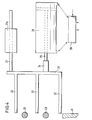
- the deflection device shown in Fig. 1 has a first transport device 12 and a second transport device 14, which e.g. can consist of a steel or plastic link chain.
- the transport devices are laterally limited by railings 15, 16 and 17.
- the second transport device runs parallel and immediately adjacent to the first transport device. In a certain area, the so-called deflection section, the railings are interrupted or angled to enable objects to be transferred from the first transport device to the second transport device.
- three objects are shown, of which the middle one is discarded, i.e. is to be deflected or diverted while the first and third objects are to be conveyed further on the first transport device.
- the middle object is carried on by the second transport device.
- a selected object is deflected by segments 18n (n stands for a, b, c ).
- the segments are fixed in the conveying direction of the transport devices and can be extended approximately perpendicular to this conveying direction.
- the segments are preferably extended approximately in the direction of the Bisector of the obtuse angle formed by the deflection surface 30 and the first transport device 12.
- the segments can consist of a vertical bracket 20 and several horizontal fingers 22.
- the length of the horizontal fingers 22 is preferably determined by the extension paths of the individual segments, so that the railing 16 interrupted at the deflection section can be replaced by one or more guide rods 23 which guide the objects cleanly when the individual segments are retracted.
- the deflection path is the area delimited by the first and last segment.
- Each segment 18 is connected to the piston 25 of a pneumatic cylinder 26 by a shaft 24. Depending on the position of a solenoid control valve 28, the segment is extended or retracted.
- the segments' contact surfaces form e.g. the leading edges of the fingers 22, a deflecting surface 30 through which the selected objects are deflected onto the second transport device.
- the segments can be extended to different extents and the contact surface of the segments is beveled against the direction of conveyance.
- the first segment 18a is extended so far that its contact surface is flush with the railing 16
- the other segments 18b to 18h are extended so far that their contact surface is flush with the contact surface of the preceding segment.
- the first segments, e.g. 18a to 18c preferably have a curved engagement surface, so that the railing 16 merges into the deflection surface 30 in a smooth curve.
- the smooth transition of the railing 16 into the deflection surface 30 enables a bumpless deflection of the selected objects even at high working speeds.
- the width of the segments 18n depends on the dimension of the objects in the conveying direction and the distance of the objects from one another.
- the width of the segments is preferably less than about half or about a third of the distance between the leading edges of successive objects. If the objects follow one another directly, the width of the individual segments should not be greater than approximately half the dimension of the objects in the conveying direction.
- the segment width should preferably be less than about a third of this dimension.
- the segments do not have to have the same width and the first segments can e.g. have a slightly larger width.
- the number of segments depends on the size of the objects and the conveying speed.
- the segments are moved in the plane of the transport devices and perpendicular to the conveying direction. However, it is also possible to retract the segments vertically from above.
- the segments can have individual fingers 22 or the contact surface of the segments can be formed by a closed metal or plastic surface.
- the angle that the deflection surface 30 forms with the conveying direction of the first transport device 12 depends on the conveying speed and is smaller the higher the conveying speed.
- An air cushion between the objects and the segments can be formed by fine air nozzles in the surface of the segments.
- Fig. 1 only a number of segments are shown, which are located on the lower edge of the first transport device in the figure.
- the inclined railing 15 can also be replaced by a series of segments, the contact surfaces of which run parallel to the conveying direction of the first transport device and which are controlled so that they have a fixed distance which corresponds to the width of the first transport device have the segments 18n.
- the further segments can be firmly connected to the segments 18n while maintaining this distance. If a jam occurs in the first transport device downstream of the deflection device, such a row of second segments is particularly advantageous since it prevents the objects from being inadvertently diverted onto the second transport device.
- extending the segments is a pure translational movement.
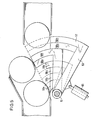
- the extension of the segments is based on a rotational movement (FIGS. 5, 6 and 10).
- the segments 58n are individually rotatably suspended on an axis 51 which is vertical, approximately at the height of the first segment 58a, directly next to the first transport device.
- Each segment is controlled by a pneumatic cylinder or by a Electromagnet 55, which acts close to the axis of rotation in order to utilize the leverage, extended.
- the segments themselves consist of preferably two angles 57, each of which has a leg 52 which is bent concentrically to the pivot point. These curved legs of the two angles end at a vertical bracket 56 which has one or more ridges on the opposite side (sliding lugs 59), along which the objects can slide.
- Stirrups and sliding lugs form an acute angle with the radius vector to the segment tip such that when segments are retracted in the conveying direction there is a smooth plane which then inevitably merges into a smooth deflection plane at any angle to the conveying direction by pivoting out the individual segments.
- a turning axis lying horizontally next to the first transport device is of course also possible as a suspension for the railing segments.
- This axis of rotation can be located both in the plane given by the surface of the transport devices and above or below this plane; the direction of the axis of rotation can be parallel to the conveying direction or to the deflection surface or can also assume an intermediate value.
- the basic idea of the invention now consists in not extending and retracting all segments at the same time, but instead extending at all times only those segments which, at this point in time or immediately afterwards, deflect the object are actually needed, ie touch this object. A deflection is thus also possible in cases in which the objects follow one another directly, ie there is no distance between them, without the objects remaining on the first transport device being impaired.
- the segments 18a to 18c that would touch the object on the left in FIG. 1 are retracted, and likewise the segments 18g and 18h are retracted because they would touch the right object. Only the segments 18e and 18f are extended, since they are just attacking the central object that is to be sorted out.
- the segment 18b has just partially retracted.
- those segments are in the extended state which attack the selected object at the relevant time or immediately thereafter.
- those segments can be in the extended state at any time, which are with the immediately preceding and the immediately following object; that remain on the first transport device, do not collide.
- the maximum number of segments is in the extended state during a deflection process.
- test line 32 which is preferably located immediately in front of the deflection path. If the test is carried out at an earlier point in time, it must be delayed or stored by suitable means, for example a shift register, in such a way that the test result is supplied to the control device for the segments at the point in time at which the object in question enters the deflection path .
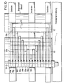
- the device for controlling the segments has the test devices mentioned above, light barriers 34a to 34h for generating a drive-in command, light barriers 35a to 35h for clearing the respective segment, and control electronics (FIG. 2).
- the control device shown in FIGS. 1 and 2 the alternative is shown in which the maximum number of segments is extended, ie all segments that do not collide with the immediately preceding and the immediately following object that are not to be deflected .
- the light barrier 35a issues a free signal.
- the free signal is delayed by a time t by a timer 40a and is given to the set input of the flip-flop la.
- the amount of the time delay depends on the speed of the first transport device, the response time of the control device and the position of the light barrier 35a.
- the free report is a prerequisite for extending a segment and the time delay should be such that the object from which the free report is derived is based on the free report moving segment is no longer hit.
- the time delay then depends on the speed of the transport device. Since the transport speed can change during operation, the delay introduced by the timer 40a is preferably variable. With a low transport speed, the time delay is greater than with a high transport speed.
- the signal obtained at the normal output of the flip-flop 1a is fed to the set input of a flip-flop 2a via an AND gate 41a.
- the second input of the AND gate 41a is connected to the normal output of a flip-flop 0, which is set by the test device and is, for example, in the set state when the object that follows the object from which the free notification was derived, should be sorted out because it is faulty, for example.
- the normal output of the flip-flop 2a controls, via a power driver, a control valve 28 which, for example, actuates a pneumatic cylinder 26 which extends the segment 18a.
- the segment 18a is always extended when an object to be deflected approaches this segment and the immediately preceding object has already moved past this segment.
- the control electronics assigned to segment 18b apart from the fact that the second input of AND gate 41b is not connected to flip-flop 0 but to the normal output of flip-flop 2a, is identical to the control electronics assigned to segment 18a.
- the segment 18b is accordingly extended when there is a free signal from the light barrier assigned to this segment and when the segment 18a is extended.
- the control electronics of the other segments is analogous to that of the segment 18b. Any segment is therefore extended if there is a free message for this segment and the preceding segment is extended.
- An entry command is derived from the front edge of each object by further light barriers 34n.
- a light barrier 34n for the entry command is also assigned to each segment 18n.
- the move-in command is delayed via timers 44n.
- the light barrier 34n for the entry command of a segment is located approximately one segment width in front of the light barrier for the free signaling of the relevant segment if timers 40n and 44n are used with the same time delay.
- the output of the timer 44a is connected to one input of an AND gate 42a.
- the other input of the AND gate 42a is connected to the inverted output of the flip-flop 0.
- An L output signal from the AND gate 42a resets the flip-flop la and the flip-flop 2a.
- a 0 signal By resetting the flip-flop 2a, a 0 signal reaches the power driver of the segment 18a and this segment is retracted thereby:
- the segment 18a is retracted when an object interrupts the retract command light barrier 34 and the flip-flop 0 is reset .
- These conditions are fulfilled or not deflected by the deflecting object of an object for the first time at the first subsequent i.
- the AND gate 42a has a double task, namely, first, an unnecessary retraction of the segments is prevented if two successive objects are to be deflected by it, and secondly, is prevented by the fact that through the retract - command derived from a deflected object a segment is retracted before this item has moved past this segment.
- the segment 1.8b is retracted when the relevant entry command light barrier 34b is interrupted by an object and the preceding segment 18a is retracted, i.e. the flip-flop 2a is reset.
- the segments 18c to 18h are retracted under analog conditions.
- the control device works in such a way that e.g. the first five segments 18a to 18e are registered. If the test device then detects a defective object, flip-flop 0 is set and the first five segments are extended practically simultaneously.
- the segments 18f., 18g etc. are only extended when they are also released, i.e. the release command light barriers 35t, 35g etc. assigned to them are no longer interrupted by the last fault-free object.
- the light barriers. 34a to 34h and 35a to 35h are located on the lines correspondingly designated in FIG. 1.
- the broken lines which are denoted by 34a to 34h and by 35a to 35h, do not represent the actual scanning lines, ie the position of the light barriers, but rather mark the point at which the The leading edge or trailing edge of the controlling object is located at the moment of the scanning, ie the generation of the control pulse.
- the conveying speed and the response time of the cylinders and valves as well as the extension and retraction times of the segments are increased consider.
- the light barriers must therefore be arranged a distance in front of the assigned segments, which essentially results from the product of the conveying speed and the sum of the response time and the extension or retraction time.
- a free signaling light barrier (dark-light transition) and an entry command light barrier (light-dark transition) are normally required for each segment. If the extension time of segment n is approximately of the same order of magnitude as the entry time of segment n + 1, then the free-signal light barrier from n and the entry command light barrier from n + 1, as shown in FIG. 1, can be combined into a single light barrier summarize, the output signal of which differentiates the edge corresponding to the light-dark transition to the entry pulse and the edge corresponding to the dark-light transition becomes the vacant signaling pulse.
- the position of the scanning systems must be selected so that with a given shape and a given distance of the objects, the individual objects can be safely distinguished from each other (resolved) and the trigger impulses (free messages, entry commands) with a certain, essentially the speed of the object dependent accuracy can be reproduced.
- bottles will be scanned at neck height, with the direction of the light barriers approximately that of the bisector of the deflection plane and the first trans port device formed obtuse angle corresponds.
- Objects which do not together form a continuous edge 36 running in the conveying direction for example cylindrical objects such as cans, can be scanned by means of light barriers (FIG. 7) which run obliquely upwards or downwards. Items that together do not form a continuous closed surface, can with suitable retro-reflective sensors are scanned from above or l oitseite from the off (Fig. 8).
- the principle of control on predecessor and successor enables a particularly favorable light barrier arrangement shown in FIG. 9.
- the light barrier transmitters 93b to 93h and 94a to 94g are integrated in the fingers 22.
- the transmitters can e.g. Infrared light-emitting diodes can also be light guides that lead to fixed light barrier units.
- the beam directions of the light barrier transmitters 93b to 93h which supply the entry commands run from the transmitters in the individual segments preferably parallel to the deflecting surface to a first light barrier receiver block 91
- the assignment of the light barriers is selected such that each of the segments 18b to 18h is retracted by an approaching light barrier by the signal of its entrance light barrier and each of the segments 18a to 18g the next segment depending on the preceding object in the case of an object to be rejected is released or extended.
- the first segment 18a is controlled by the test light barrier (test line 32).
- the position of transmitter and receiver can also be interchanged so that blocks 91 and 92 are transmitters and the receivers are in the segments.
- the course of the individual objects can also be followed by inductive or capacitive proximity switches, ultrasonic, air barriers etc. or with video (CCD) cameras.
- inductive or capacitive proximity switches ultrasonic, air barriers etc. or with video (CCD) cameras.
- CCD video
- Such camera systems are not only used for objects that are difficult to resolve, but also for deflection devices that have to process different embodiments of certain objects in alternating operation (e.g. fill level and closure control in beverage bottling systems that can be set on several bottle types).
- a further advantage is that with several objects that are deflected one after the other, regardless of the distances between these objects, the segments are extended only once and with the next following object that is not to be rejected, since it e.g. error-free, can be retracted. If the clearance notification and the entry command were derived from an object itself instead of from the preceding and the following object, the segments for each individual object would be extended and retracted in the aforementioned case.
- control is independent of the shape and position of an object. If, on the other hand, the control is derived from the object to be deflected itself, the detection of various types of objects by means of light barriers becomes difficult or impossible. For example, by controlling the segments depending on the preceding and following items, it becomes possible to make bottles of other shapes, e.g. sort out square bottles, or overturned bottles and even bottle bottoms and generally broken bottles and broken glass. This is not possible with known sorting devices.
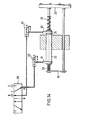
- each double-acting cylinder 26 of the segments carries a helical compression spring on each cylinder side.
- the spring travel is short in relation to the stroke length of the piston, e.g. half as long, and their forces are dimensioned and counter bearings are arranged at such distances from the piston that the springs in the end positions are compressed between about 2 and 15 mm (depending on the stroke length) until the forces are balanced.
- the yoke 64 and the bracket 20 form the counter bearings.
- the end position of the piston is therefore the position in which the spring force is equal to the piston force generated by the pressure force.
- the springs can also be arranged within the cylinder or can be designed as leaf springs.
- springs with a constant spring rate Normally you can use springs with a constant spring rate. However, if the share of kinetic energy is very high or only minimal overshoot is required in the end position, springs with an exponential or progressive characteristic curve or several concentrically arranged springs with different spring rates must be used.
- one port 61 is now pressurized with compressed air, i.e. the railing segment is extended (Fig. 14) and the left spring is compressed. If the control electronics now switches the control valve 28 so that after the delay due to the switching time of the control valve 28 the other port 62 is pressurized with compressed air and the one port 61 is relieved, the piston rod will immediately move to the left because the force of the clamped Spring 29, which is equal to the piston force, is sufficient in itself to overcome the static friction of the piston and to expel the air in the opposite cylinder chamber via the quick exhaust valve 63 and the control valve 28.
- springs 29 has another advantage in addition to shortening the breakaway time:
- a yoke 64 In the case of two parallel cylinders 26 for a single segment, the piston rods of which are connected by a yoke 64 (FIG. 15), synchronism problems normally occur as a result of different breakaway times, which lead to tilting of the pistons 25 and rapid destruction of the bearings of the piston rods.
- static friction is overcome by springs 29, the breakaway times of the two pistons connected by the yoke 64 are essentially the same, so that no canting occurs.
- FIGS. 16 to 19 show a particularly preferred embodiment in which the deflection devices are formed by fixed air nozzles 70 which are arranged in the railing 16.
- the intensity of the air jets generated by the air nozzles can be staggered and increase in the conveying direction.
- the intensity of the air nozzles 70 is set such that an object to be deflected is gradually shifted from the first transport device 12 to the second transport device 14.
- the nozzles 70 are expediently controlled by the object to be deflected, i.e. on and off. Any other suitable fluid can be used instead of air.
- the fixed air nozzles 70 produce an air cushion which in principle behaves exactly like the deflection surface 30 described above, on which the object can slide.
- the advantages of the deflection devices in the form of air nozzles are the higher working speed (no more inert masses can be moved) and the lower wear of the deflection device.
- a detection device determines the speed component perpendicular to the transport device and / or the distance of the object to be deflected from the air nozzles 70. On the basis of this information, the air nozzle control device can limit the number of blowing nozzles in such a way that an optimal deflection to the second transport device is ensured.
- the frictional resistance between the object and the transport device again reduces the speed perpendicular to the transport direction, so that, with a suitable choice of the switch-off time, it is even possible to avoid bumping into the outer railing of the second transport device.
- the steepness of the deflection curve depends on the mass of the objects, the transport speed, the friction and the intensity gradation of the nozzles. This staggering of the intensities and the intensities themselves are chosen in such a way that a flat deflection curve is created for unstable objects.
- All nozzles can also blow with the same intensity.
- This version saves the throttle valves in front of some of the nozzles.
- the first nozzles can blow with a high intensity in order to overcome the static friction between the object to be discharged and the transport device and to accelerate it perpendicular to the direction of transport, while the subsequent nozzles are weaker in intensity and only the glide Compensate for the friction of the object. This results in a flat deflection curve and is therefore advantageous for unstable objects. It is also possible to slowly increase the intensities of the last nozzles again, since the greater the distance from the nozzles, the less the force acting on the object to be deflected. Furthermore, the intensity of the last nozzles can be weakened to ensure braking due to the increasing influence of sliding friction.
- Unstable objects of relatively great height can be discharged with several rows of nozzles one above the other instead of with a row of nozzles that let their pressure forces attack in the centers of gravity of the objects.
- the individual deflection devices would thus consist of a plurality of nozzles lying one above the other. The nozzles of a deflection device do not have to blow with the same intensity.
- the risk of objects to be distracted falling over can e.g. are reduced by the fact that the lower nozzles blow with a higher intensity (point of application of the strongest deflecting force, approximately equal to the point of application of the strongest counterforce).
- the angle with respect to the transport direction in which the nozzles blow depends not only on the consequent density and the stability properties but also on the relative speed of the second transport device or whether the speed is decelerated or accelerated during the diversion process or remains the same. For example, if the second transport device runs slower than the first, the air nozzles 70 simultaneously brake the objects to be deflected by blowing something against the conveying direction. The air jets do not all have to blow at the same angle to the conveying direction. To slow down the objects to be deflected, the last nozzles, for example, can be inclined to an increasing extent against the conveying direction.
- the distance in the transport direction between the individual deflection devices depends on the diameter of the objects to be discharged and on the desired shape of the air cushion.
- a nozzle spacing of less than d results in a continuous air cushion on which an object is deflected smoothly, since at any point in time the blowing jet hits the object at least one nozzle.
- the continuous air cushion will increasingly dissolve into individual air blasts (air cushions in front of each individual nozzle).
- the smooth deflection becomes a gradual shifting onto the second transport device, the static friction of the object to be deflected having to be overcome through each nozzle if the object comes to a standstill on the first transport device between the individual deflection devices.
- the distance between the nozzles 70 is preferably smaller than the diameter of the objects.
- a multi-channel deflection can also be implemented. Depending on which distraction device the nozzle is no longer switched on, the object is deflected onto a specific one of the second transport devices.
- the signals emitted by the detection device can also influence the operation of the nozzles in another way:
- the nozzles of all subsequent deflection devices are switched off or not switched on.
- the detection device provides data on the extent of the distraction that has already taken place.
- a microprocessor used for control continuously analyzes this data and controls the air cushion switch in such a way that all objects describe the same, as flat as possible, deflection curve regardless of their weight and the transport speed. If, for example, it turns out that a light object is deflected on a deflection curve that is too steep, the air nozzle control device reacts by reducing the intensity or shortening the operating time of the nozzles.
- the detection device in the deflection section must provide as much and exact distance data as possible, and possibly several valves with pressure reducers per nozzle must be provided or the duty cycle of the nozzles must be shortened.
- the detection device not only has to deliver distance and / or speed data, it also has to deliver another signal or data indicating the position of the measuring point in the transport direction. This enables the unambiguous assignment of a measured value to an object to be deflected and so the control program of the microprocessor (or the control electronics) can then abort the blow-out sequence belonging to one object while another object is being blown out further.
- Such detection devices can be implemented with several optical angle sensors, reflex sensors, and inductive and capacitive sensors, light or ultrasonic transit time measuring devices, one or more CCD cameras or video cameras etc.
- Ultrasonic transducers 71 are preferably used as the detection device.
- ultrasonic transducers 71 can be recorded by ultrasonic transducers 71 and the desired information about the speed and distance can be obtained through a downstream evaluation electronics hold.
- a distance can be determined by a simple amplitude evaluation or by measuring the transit time of the acoustic frequency mixture generated in the deflection process.
- one or more stabilizing nozzles 72 provided that are attached obliquely in the direction of travel relative to the deflection devices and at a height above the center of gravity of the objects to be diverted and blow against the deflection direction to stabilize the objects to be deflected. It may be expedient to align the stabilizing nozzles 72 obliquely upwards in order to reduce disturbing turbulence.
- stabilizing nozzles are activated in such a way that the stabilizing nozzles are switched on immediately after the last deflection device that was switched on or activated. As with the deflection devices in the form of segments, the stabilizing nozzles can also be switched on in succession in accordance with the further movement of the object.
- the arrangement of the stabilizing nozzles depends on the type of second transport device.
- the use of the stabilizing nozzles is not limited to the deflection by means of the aforementioned embodiments of the deflection device.
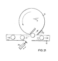
- Other deflection devices e.g. simple pushers 75, deflected objects and objects that generally tip over at critical points can be stabilized, in particular by the arrangement of air nozzles on both sides of a conveyor (FIG. 21).
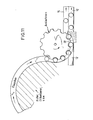
- the deflection device according to the invention can also be used in connection with the outlet star of a filling device, a labeling machine, etc. 11, the Deflection devices are arranged in such a way that the bottles can leave the outlet star on the transport device 12 when the deflection devices are retracted or switched off, while the bottles are taken from the discharge star to a second transport device 14, a turntable, etc. when the deflection devices are extended or switched on.
- the version described with ultrasonic transducers works reliably for bottle weights between 0.15 and 1.5 kg at transport speeds between 0.5 and 1.5 m / sec, or between 0.5 and 2.5 m / sec at max. 0.4 kg bottle weight.
- Upwards, speeds and weights are relatively uncritical, since the number of nozzles can be increased as desired, while light objects are deflected very steeply at slow speeds, and therefore place high demands on the measuring devices.
- the nozzles of the first segments 6 are attenuated in their intensity by reducing valves and graded according to increasing intensity before l preferably.
- the opposite railing 15 only bends directly in the deflection section (outer railing of the second transport device).
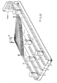
- catch tabs 76 (FIG. 23) which prevent the rejected bottles from hitting the railing 15 hard.
- the catch flags which are attached opposite the fourth and subsequent segments, also serve as shutdown devices by acting on inductive proximity switches. The ultrasonic transducers are therefore not in this embodiment needed. Such forced guidance of the rejected bottles allows the speed to be varied from zero upwards.
- FIG. 12 shows another possible combination of the deflection device according to the invention with a transport star.
- This arrangement is particularly advantageous under dynamic pressure.
- the main stream of objects is rotated in the direction by 90 ° by the deflecting surface 30 and sluiced onto a transport device.
- the objects to be deflected determined by an inspector, on the other hand, continue straight ahead.
- the control method described above is reversed. By changing the direction of the main flow of the objects it is achieved that e.g. the back pressure occurring in a production line remains without influence on the device and can be sorted out in the production line under full back pressure.
- the deflection device according to the invention can also be used in such a way that the objects are optionally deflected by a first transport device onto various further transport devices.
- several devices of the type shown in FIG. 1 can be connected in series.
- the first transport device and the screw run parallel to the deflecting surface of the rows of deflecting devices.
- the deflection devices are preferably extended vertically from top to bottom.
- the deflection devices namely segments that can be displaced approximately perpendicular to the conveying direction and gas nozzles.
- the deflection devices for example suction nozzles, which are arranged on the kinking part of the railing 15 and gradually deflect the objects to be deflected by generating a negative pressure on the side facing the second transport device (FIG. 22).
- Objects with pronounced magnetic properties can also be deflected by deflection devices in the form of magnetic coils, the magnetic coils likewise being arranged in the kinking part of the railing 15.
- the speed of the virtually moving fluid cushion is approximately equal to the speed of the first transport device
- the speed of the respective force field in the devices working with suction nozzles 80 and deflecting magnets is determined by the quotient of the speed of the first transport device and the cosine of the angle at which the objects are deflected be determined.
- the deflection force can also be generated, for example, by electrical fields.
- the electrical fields can be generated by a large number of capacitor plates which are arranged in the outer railings 15, 16.
- the deflection devices are stationary in the conveying direction and that each deflection device exerts such a force on an object to be deflected that it is deflected by a partial amount of the total deflection from the first transport device to the second transport device.
- the force exerted on the object can be both a pushing and a pulling force.
- the suction nozzles 80 can also be controlled via a rotary slide valve. Shortly before and in the kinking part of the railing 15 there is a large number (about 100) of suction nozzles 80 (for example 15 mm wide) close together.
- the feed lines lead to a rotary slide valve control 81, which is coupled to the drive of the transport device, the gear ratio correspondingly being translated (for example 1: 1.06 at 20 °).
- This rotary slide control 81 opens and closes the feed lines to the suction nozzles in such a way that individual vacuum areas (eg 3 nozzles wide) virtually move along the deflection path at fixed intervals of eg 3 nozzles. About half of all suction nozzles are therefore constantly switched on, so that the vacuum generated by the suction fan remains relatively constant.
- the objects arriving on the first transport device are clocked into the sequence of the vacuum areas by a screw.
- the timing can also be done by several suction nozzles in the introductory straight part of the railing. Then the objects are guided closely along the suction nozzles.
- Deflection devices that exert a pulling force are particularly suitable for devices that work with several second transport devices.
- the objects are guided through a suction device leading over all second transport devices with a number of suction nozzles to the desired second transport device and then released.
- Certain suction nozzles or suction nozzle groups are provided with compressed air injectors which can be controlled via solenoid valves and, in the activated state, prevent the formation of a vacuum area in front of the suction nozzle in question.
- the object drawn along the railing can thus be detached from the suction nozzles at predetermined locations.
- the deflection devices are controlled in the manner described in connection with the air nozzle deflection devices, namely as a function of the further movement of the object to be deflected.
- the invention is also applicable to deflection devices in which the objects are not transported on transport devices, but rather move on a trajectory determined by the gravity of the earth or fall freely.
- deflection devices in which the objects are not transported on transport devices, but rather move on a trajectory determined by the gravity of the earth or fall freely.
- a beverage filling system is described below, which is set up to fill different cylindrical bottle types (diameter 50-90 mm) in alternating operation, whereby the filled bottles are checked for closure and fill level and then a good -Poor sorting is performed.
- a second transport device 14 In the deflection section, parallel to the first transport device 12 in the form of a steel link chain on which the production line runs, runs a second transport device 14 at a distance of approximately 5 to 10 mm, which is used to remove the deflected bottles.
- the stationary side railing 15 of the first transport device 12 bends in the deflection section parallel to the deflection plane and becomes the outer railing 15 of the second transport device 14.
- the second railing 16 of the first transport device 12 consists of two superimposed ones Guide rods 23 which can be displaced inwards and outwards perpendicularly to the conveying direction in order to adapt to different bottle diameters.
- the two transport devices have a common fixed railing 17 immediately after the deflection section, by means of which mixing after the deflection is avoided.
- the deflection device itself consists of 9 individually extendable segments 18, which are strung together. These segments each consist of 3 fingers 22, which are fastened to a vertical bracket 20 such that one can be extended just over the steel link chain, one between and one over the two guide rods 23.
- the length of the fingers 22 is determined by the extension path; for example, in this embodiment the shortest finger (segment 18a) is approximately 30 mm and the longest finger (segment 18i) is approximately 115 mm long.
- the fingers 22 are chamfered on their front side in such a way that in the extended state they form a smooth deflection plane which is approximately at an angle of 30 ° to the conveying direction.
- the first segment 18a has a slight curvature so that the bottles are guided in a smooth transition from the conveying direction to the deflection direction.
- the first segment 18a with a width of approximately 28 mm is somewhat wider than the remaining 8 segments, all of which have a width of 20 mm.
- the extension direction forms at. this version with the conveyor an angle of 105 °.
- a guide rod 27 is fastened on the side opposite the fingers at the upper end, which is guided in plastic bushings 27a and thus gives the segment the necessary stabilization.
- the piston rod of the pneumatic cylinder 26 used as an actuator engages approximately in the middle of the bracket.
- the cylinder 26 is controlled by an electrically operated 5/2-way valve as a control valve 28.
- All segments and actuators are mounted on a base plate that can be moved together with the railing guide rods.
- test line about 15 cm in front of the first segment is represented by a trigger light barrier that FF 0 sets or does not set depending on the two test conditions level / closure.
- a 256 x 1 element CCD camera is used to determine the position of the predecessor and the successor of a bottle to be rejected.
- Appropriate optics are used to image an approximately 35 cm long horizontal scanning line, which begins approx. 3 cm behind the test line and lies at the neck height of the bottle type to be sorted, on the CCD-IC.
- An evaluation logic then tracks the position of the individual bottle necks and uses them to take the free messages into account, taking into account the specified bottle diameter and drive-in pulses which are further processed by the basic circuit shown in FIG. 2.
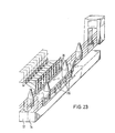
- a deflection device with air nozzles is described below with reference to FIGS. 16 to 19. Otherwise, the statements made in Example 1 apply.
- the deflection device consists of 10 individually controllable deflection devices, the distance between two deflection devices in each case being approximately 2 cm.
- the deflection devices each consist of a 15 cm high vertical support to which two 5 cm high flat jet nozzles are attached so that the longer dimension of the nozzle opening is vertical.
- Each flat jet nozzle consists of 16 round full jet nozzles with a diameter of 0.5 mm arranged one above the other be fed from a common compressed air source. The lower edge of the lower flat jet nozzle is flush with the upper edge of the transport devices, while the lower edge of the upper flat jet nozzle is approximately 10 cm above the level of the transport devices.
- the nozzles are aligned so that they blow perpendicular to the conveying direction and parallel to the plane of the transport device.
- Both nozzles are connected to a 2/2-way valve of 1/4 inch via two hoses of equal length, whereby the intensity of the upper flat jet nozzle is somewhat weakened by a reducing valve in the supply line.
- All lower nozzles of the sorting device blow with the same intensity; likewise the upper ones, but with a lower intensity than the lower ones.
- An ultrasonic transducer 71 is fastened between the deflection devices b and c, d and e, f and g, h and i, approximately 10 cm above the level of the transport device.
- a test line 32 (trigger light barrier) about 15 cm in front of the first deflection device determines whether the two test conditions fill level and closure are met or not.
- the microprocessor-operated air nozzle controller "remembers" the defective bottle, i.e. the position on the transport device (link chain) where it is located.
- a multiple inductive scanner 74 (FIG. 20)
- a clock signal is given to the control system for each 6 mm link chain feed.
- This multiple inductive scanner (Fig. 20) consists of 6 individual inductive proximity switches, which are mounted close to the link chain with 44.3 mm center distances. The hinges of the link chain, which slide over the initiators at 38.1 mm centers, then generate the desired clock pulses. By summing up these pulses, the control "knows" exactly when the defective bottle is in front of segment a, b, c, etc.
- the transport speed is calculated from the clock pulses of the inductive scanner and the valves in question are activated earlier (fast) or later (slowly) depending on the transport speed.
- a rotating air cushion (air wave) is generated by successively switching on the nozzles.
- the impact of the air on the surface of the bottle to be deflected generates ultrasound. This is recorded by one of the converters described above, selectively rectified via amplifiers (38 - 40 kHz) and compared with a setpoint.
- the air nozzle control device prevents further nozzles from being switched on, so that the air cushion for the deflected bottle disappears. For light bottles with slow transport speed this will happen very early, while heavy bottles with high transport speed need an air cushion (air wave) moving along the entire deflection path.
- the version described here is suitable for cylindrical bottles with a diameter of 56 mm and has an output of up to 50,000 bottles per hour (belt speed about 1.5 m / sec).
- the bottles that cannot be rejected may not move on the first transport device (no drift).
- the structure of the transport devices is the same as in Example 1, with the exception that the railing 16 is interrupted in the deflection section.
- the deflection device in turn consists of 9 individually extendable segments which are lined up closely together.
- the segments each consist of a vertical, 100 mm high and about 20 mm wide (the first segment has a width of 25 mm) plastic bracket with 4 ridges (sliding tabs) along which the bottles slide.
- the segments are extended and retracted by double-acting cylinders (16 mm piston diameter) with a continuous piston rod; these cylinders are controlled by electrically operated 5/2 way valves with quick exhaust.
- the piston rods each carry two 30 mm long springs.
- the spring constants are dimensioned so that the springs of the first segment (extension - 6 mm) pass through the piston force about 2'mm, that of the second segment (extension 11 mm) about 4 mm, that of the third segment (extension 17 mm) about 7 mm, that of the fourth segment (extension 24 mm) about 10 mm, that of fifth segment (extension 32 mm) and the following segments are compressed by about 12 mm.
- a guide rod is attached to the segments above the cylinders and is connected to the piston rod on the other side by a yoke.
- the cylinders sit in a carrier block made of plastic, which is also a slide bearing for the guide rods.
- control principle described above is applied to the predecessor and successor of the object to be rejected, implemented in a microprocessor program.
- a test line about 15 cm in front of the first deflection segment is used to determine whether the two conditions level / closure are met or not.
- a clock signal is sent to the control system for every 4.76 mm link chain feed via an 8-fold inductive scanner submitted.
- the microprocessor control system follows the course of the bottles that cannot be rejected or their position on the link chain. Since the diameter of the bottles that cannot be rejected is known (in this case 56 mm), the control unit can always extend the maximum possible number of railing segments between two error-free bottles in the event of an error message from the test facility. However, the control must also take into account the positioning times of the individual segments, since the transport speed varies constantly (0 to 1.5 m / sec). In accordance with the respective transport speed, which is automatically calculated from the time interval between the clock pulses, the microprocessor repeatedly calculates the necessary advance of its control points (retraction - extension) for each individual cylinder and takes this into account in the control.
Abstract
Eine Vorrichtung zum seitlichen Ablenken von bestimmten, nach einem Merkmal ausgewählten Gegenständen (z.B. Flaschen) von einer ersten Bewegungsbahn (12) auf eine zweite Bewegungsbahn (14) weist mehrere nebeneinander angeordnete Ablenkeinrichtungen (18a - i) auf. Die Ablenkeinrichtungen (18a - i) bilden zusammen eine Ablenkfläche und sind in Richtung der Bewegung der abzulenkenden Gegenstände ortsfest. Die abzulenkenden Gegenstände werden durch die Ablenkeinrichtungen (18a - i) schrittweise von der ersten Bewegungsbahn (12) auf die zweite Bewegungsbahn (14) abgelenkt, wobei jede Ablenkeinrichtung jeden abzulenkenden Gegenstand um einen Teilbetrag seitlich ablenkt. Die Vorrichtung arbeitet dadurch auch bei räumlich und zeitlich dicht aufeinander folgenden Gegenständen zuverlässig und mit hoher Geschwindigkeit.A device for the lateral deflection of certain objects (e.g. bottles) selected according to a characteristic from a first movement path (12) to a second movement path (14) has a plurality of deflection devices (18a-i) arranged next to one another. The deflection devices (18a-i) together form a deflection surface and are stationary in the direction of the movement of the objects to be deflected. The objects to be deflected are gradually deflected by the deflection devices (18a-i) from the first movement path (12) to the second movement path (14), each deflection device laterally deflecting each object to be deflected by a partial amount. As a result, the device operates reliably and at high speed even in the case of objects which are spatially and temporally close to one another.
Description
Vorrichtung zum seitlichen Ablenken von Gegenständen von einer ersten Bewegungsbahn auf eine zweite Bewegungsbahn.Device for the lateral deflection of objects from a first trajectory to a second trajectory.
Die Erfindung betrifft eine Vorrichtung zum seitlichen Ablenken von Gegenständen von einer ersten Transporteinrichtung auf eine zweite Transporteinrichtung. Derartige Vorrichtungen sind Teil von zum Beispiel Anlagen, die Flüssigkeiten in Behälter, wie Flaschen, abfüllen, und dienen dazu, fehlerhafte Behälter, die nicht für den Verkauf geeignet sind, zum Beispiel nicht vollständig gefüllte Flaschen oder nicht ordnungsgemäss verschlossene Flaschen, auszusondern.The invention relates to a device for the lateral deflection of objects from a first transport device to a second transport device. Such devices are part of, for example, systems that fill liquids into containers, such as bottles, and are used to separate out defective containers that are not suitable for sale, for example bottles that are not completely filled or bottles that are not properly closed.
Aus der DE-OS 2 358 185 ist eine Ablenkvorrichtung bekannt, bei der die Gegenstände, zum Beispiel die Flaschen, durch Stössel, die mit der ersten Transporteinrichtung mitlaufen, von dieser auf die zweite Transporteinrichtung verschoben werden. Die Stössel werden durch eine Weiche auf eine Führungsbahn geleitet, durch die sie quer zur Förderrichtung verschoben werden. Um bei dieser bekannten Vorrichtung zu verhindern, dass die auszusondernden Gegenstände von den Stösseln abgleiten, muss die Breite der Stössel etwa dem Durchmesser der Gegenstände entsprechen. Die auszusondernden Gegenstände dürfen ausserdem nicht in dichter Folge ankommen, sondern müssen durch eine geeignete Einrichtung vereinzelt werden, das heisst, der Abstand zwischen den Gegenständen muss eine gewisse Mindestgrösse besitzen. Die aus dieser Druckschrift bekannte Vorrichtung besitzt daher zwangsläufig eine relativ grosse Abmessung, wodurch zum Beispiel das Ausleiten der Gegenstände auf sogenannte Drehteller erschwert wird. Eine ähnliche Vorrichtung ist aus der US-PS 3 361 247 bekannt.A deflection device is known from DE-OS 2 358 185, in which the objects, for example the bottles, are moved from the latter to the second transport device by means of plungers which move with the first transport device. The plungers are guided through a switch to a guideway, through which they are moved transversely to the conveying direction. In order to prevent the objects to be separated from sliding off the plungers in this known device, the width of the plunger must correspond approximately to the diameter of the objects. The items to be separated out must also not arrive in close succession, but rather must be separated by a suitable device, that is, the distance between the objects must have a certain minimum size. The device known from this document therefore inevitably has a relatively large dimension, which, for example, makes it difficult to discharge the objects onto so-called turntables. A similar device is known from US Pat. No. 3,361,247.
Aus der DE-OS 2 555 192 ist eine Vorrichtung zum Ablenken von Gegenständen bekannt, wobei die Transporteinrichtung aus einzelnen schmalen Riemen besteht, die über Walzen laufen. Die Gegenstände werden durch einen Kamm abgelenkt, der von unten zwischen den Riemen nach oben geschoben wird. Diese Vorrichtung ist nur in Fällen anwendbar, in denen der Abstand zwischen den einzelnen Gegenständen relativ gross ist, so dass sich die gleichen Nachteile ergeben, wie bei der DE-OS 2 358 185.From DE-OS 2 555 192 a device for deflecting objects is known, wherein the transport device consists of individual narrow belts that run over rollers. The objects are deflected by a comb, which is pushed upwards between the belts. This device can only be used in cases in which the distance between the individual objects is relatively large, so that the same disadvantages arise as in DE-OS 2 358 185.
Die Aufgabe der Erfindung besteht in einer Vorrichtung zum seitlichen Ablenken von Gegenständen von einer ersten Transporteinrichtung auf eine zweite Transporteinrichtung, die auch bei räumlich und zeitlich dicht aufeinanderfolgenden Gegenständen mit hoher Geschwindigkeit und zuverlässig arbeitet und einen geringen Platzbedarf aufweist.The object of the invention is a device for the lateral deflection of objects from a first transport device to a second transport device, which works reliably and at high speed even with spatially and temporally closely spaced objects and requires little space.
Diese Aufgabe wird dadurch gelöst, dass die auszusondernden Gegenstände dadurch abgelenkt werden, dass durch Ablenksegmente eine Ablenkfläche gebildet wird, entlang der die Gegenstände von der ersten Transporteinrichtung auf die zweite Transporteinrichtung geführt werden. Die Ablenksegmente sind in Förderrichtung ortsfest, senkrecht dazu jedoch ein- und ausfahrbar, wobei jeweils nur diejenigen Ablenksegmente ausgefahren sind, die sich zu einem bestimmten Zeitpunkt mit dem abzulenkenden Gegenstand in Berührung befinden. Die Ablenkfläche wird also unmittelbar vor dem Gegenstand aufgebaut und unmittelbar nach dem Gegenstand wieder abgebaut.This object is achieved in that the objects to be separated out are deflected in that a deflecting surface is formed by deflecting segments, along which the objects are guided from the first transport device to the second transport device. The deflection segments are stationary in the conveying direction, but can be retracted and extended perpendicularly thereto, only those in each case Deflection segments are extended that are in contact with the object to be deflected at a certain time. The deflection surface is thus built up directly in front of the object and dismantled again immediately after the object.
Nach einer bevorzugten Ausführungsform wird die Ablenkfläche durch die von Düsen erzeugten Luftstrahlen gebildet. Mit dieser Ausführungsform lassen sich besonders hohe Arbeitsgeschwindigkeiten erreichen.According to a preferred embodiment, the deflection surface is formed by the air jets generated by nozzles. With this embodiment, particularly high working speeds can be achieved.
Ausführungsbeispiele der Erfindung werden nachfolgend anhand der Zeichnung erläutert. Es zeigen:
- Fig. 1 in Draufsicht eine Vorrichtung mit mechanisch arbeitenden geradlinig ausfahrbaren Segmenten; .
- Fig. 2 die Steuerungslogik für eine Vorrichtung nach Fig. 1;
- Fig. 3 in Draufsicht eine Vorrichtung ähnlich Fig. 1 mit unter einem Winkel ausfahrbaren Segmenten;
- Fig. 4 ein Segment im Querschnitt und mit Blickrichtung in Förderrichtung;
- Fig. 5 in Draufsicht eine Vorrichtung mit um eine Achse verschwenkbaren Segmenten;
- Fig. 6 in einer perspektivischen Darstellung ein Segment der in Fig. 5 gezeigten Ausführungsform;
- Fig. 7, 8 und 9 Möglichkeiten für den Verlauf von Lichtschranken bei dicht aufeinanderfolgenden Gegenständen;
- Fig. 10 in Seitenansicht die Anordnung der Segmente der Vorrichtung von Fig. 5 und 6;
- Fig. 11 die Anwendung der Vorrichtung in Verbindung mit einem Auslaufstern;
- Fig. 12 die Anwendung einer Vorrichtung als Eckstation;
- Fig. 13 eine Vorrichtung mit mehreren parallelen zweiten Transporteinrichtungen;
- Fig. 14 und 15 eine Ausführungsform, bei der das Aus- und Einfahren der Segmente durch Druckfedern unterstützt wird;
- Fig. 16, 17 und 18 eine Ablenkvorrichtung, bei der die Ablenkeinrichtungen durch Gasdüsen gebildet werden;
- Fig. 19 eine Ausführungsform, ähnlich der von Fig. 18, wobei zusätzliche Gasdüsen zum Abbremsen der abgelenkten Gegenstände vorgesehen sind;
- Fig. 20 einen Vielfach-Induktivabtaster zur Erzeugung der für die Steuerung der Ablenkeinrichtung benötigten Taktimpulse;
- Fig. 21 eine Ausführungsform, bei der auf jeder Seite der zweiten Transporteinrichtung Stabilisierungsdüsen vorgesehen sind;
- Fig. 22 eine erfindungsgemässe Vorrichtung mit Ablenkeinrichtungen in Form von Saugdüsen und
- Fig. 23 eine Ausführungsform, ähnlich der von Fig. 19, wobei Auffangfahnen anstatt der Stabilisierungsdüsen vorgesehen sind.
- Figure 1 is a plan view of a device with mechanically operating straight extendable segments. .
- FIG. 2 shows the control logic for a device according to FIG. 1;
- 3 shows a top view of a device similar to FIG. 1 with segments which can be extended at an angle;
- 4 shows a segment in cross section and looking in the conveying direction;
- 5 shows a top view of a device with segments pivotable about an axis;
- FIG. 6 shows a perspective illustration of a segment of the embodiment shown in FIG. 5;
- FIGS. 7, 8 and 9 options for the course of light barriers in closely consecutive objects;
- 10 shows a side view of the arrangement of the segments of the device from FIGS. 5 and 6;
- 11 shows the use of the device in connection with an outlet star;
- 12 shows the use of a device as a corner station;
- 13 shows a device with a plurality of parallel second transport devices;
- 14 and 15 an embodiment in which the extension and retraction of the segments is supported by compression springs;
- 16, 17 and 18 a deflection device in which the deflection devices are formed by gas nozzles;
- 19 shows an embodiment similar to that of FIG. 18, additional gas nozzles being provided for braking the deflected objects;
- 20 shows a multiple inductive scanner for generating the clock pulses required for controlling the deflection device;
- 21 shows an embodiment in which stabilizing nozzles are provided on each side of the second transport device;
- 22 shows a device according to the invention with deflection devices in the form of suction nozzles and
- Fig. 23 shows an embodiment, similar to that of Fig. 19, where catch flags are provided instead of the stabilizing nozzles.
Die in Fig. 1 gezeigte Ablenkvorrichtung besitzt eine erste Transporteinrichtung 12 und eine zweite Transporteinrichtung 14, die z.B. aus einer Stahl- oder Kunststoff-Gliederkette bestehen können. Die Transporteinrichtungen sind seitlich durch Geländer 15, 16 und 17 begrenzt. Die zweite Transporteinrichtung verläuft parallel und unmittelbar benachbart zur ersten Transporteinrichtung. In einem bestimmten Bereich, der sogenannten Ablenkstrecke, sind die Geländer unterbrochen bzw. abgewinkelt, um ein Überleiten von Gegenständen von der ersten Transporteinrichtung auf die zweite Transporteinrichtung zu ermöglichen. In Fig. 1 sind drei Gegenstände dargestellt, von denen der mittlere ausgesondert, d.h. abgelenkt oder ausgeleitet werden soll, während der erste und dritte Gegenstand auf der ersten Transporteinrichtung weiter befördert werden sollen. Der mittlere Gegenstand wird von der zweiten Transporteinrichtung weiter befördert. Das Ablenken eines ausgewählten Gegenstandes erfolgt durch Segmente 18n (n steht für a, b, c...). Die Segmente sind in Förderrichtung der Transporteinrichtungen fest angeordnet und können etwa senkrecht zu dieser Förderrichtung ausgefahren werden.The deflection device shown in Fig. 1 has a
Da die auszuleitenden Gegenstände im allgemeinen durch die Ablenkflächein Förderrichtung geringfügig abgebremst werden, und sich so der Abstand zum vorausgehenden Gegenstand, der nicht ausgeleitet wird, vergrössert bzw. sich der Abstand zu dem nachfolgenden Gegenstand verkleinert, erfolgt das Ausfahren der Segmente vorzugsweise etwa in Richtung der Winkelhalbierenden des von der Ablenkfläche 30 und der ersten Transporteinrichtung 12 gebildeten stumpfen Winkels.Since the objects to be rejected are generally braked slightly by the deflecting surface in a conveying direction, and thus the distance to the preceding object that is not rejected increases or the distance to the following object decreases, the segments are preferably extended approximately in the direction of the Bisector of the obtuse angle formed by the
Die Segmente können aus einem senkrechten Bügel 20 und mehreren waagrechten Fingern 22 bestehen. Die Länge der waagrechten Finger 22 wird vorzugsweise von den Ausfahrwegen der einzelnen Segmente bestimmt, so dass das an der Ablenkstrecke unterbrochene Geländer 16 durch einen oder r.ehrere Leitstäbe 23 ersetzt werden kann, die die Gegenstände sauber führen, wenn die einzelnen Segmente eingefahren sind. Die Ablenkstrecke ist der durch das erste und letzte Segment begrenzte Bereich. Durch einen Schaft 24 ist jedes Segment 18 mit dem Kolben 25 eines pneumatischen Zylinders 26 verbunden. In Abhängigkeit von der Stellung eines Magnet-Steuerventils 28 wird das Segment ausgefahren oder eingefahren.The segments can consist of a
Im ausgefahrenen Zustand bilden die Angriffsflächen der Segmente, z.B. die Vorderkanten der Finger 22, eine Ablenkfläche 30, durch die die ausgewählten Gegenstände auf die zweite Transporteinrichtung abgelenkt werden. Die Segmente sind unterschiedlich weit ausfahrbar und die Angriffsfläche der Segmente ist entgegen der Förderrichtung abgeschrägt. Zum Ablenken eines Gegenstandes wird das erste Segment 18a so weit ausgefahren, dass seine Angriffsfläche mit dem Geländer 16 bündig ist, und dann werden die übrigen Segmente 18b bis 18h soweit ausgefahren, dass ihre Angriffsfläche jeweils bündig mit der Angriffsfläche des vorausgehenden Segmentes ist. Die ersten Segmente, z.B. 18a bis 18c, besitzen vorzugsweise eine gekrümmte Angriffsfläche, so dass das Geländer 16 in einer glatten Kurve in die Ablenkfläche 30 übergeht. Durch den glatten Übergang des Geländers 16 in die Ablenkfläche 30 wird auch bei hohen Arbeitsgeschwindigkeiten ein stossfreies Ablenken der ausgewählten Gegenstände ermöglicht.When extended, the segments' contact surfaces form e.g. the leading edges of the
Die Breite der Segmente 18n hängt von der Abmessung der Gegenstände in Förderrichtung und dem Abstand der Gegenstände voneinander ab. Die Breite der Segmente ist vorzugsweise kleiner als etwa die Hälfte oder etwa ein Drittel des Abstandes der Vorderkanten aufeinanderfolgender Gegenstände. Folgen die Gegenstände unmittelbar aufeinander, so soll die Breite der einzelnen Segmente nicht grösser sein als etwa die Hälfte der Abmessung der Gegenstände in Förderrichtung. Vorzugsweise soll die Segmentbreite kleiner als etwa ein Drittel dieser Abmessung sein. Die Segmente müssen nicht gleiche Breite haben und die ersten Segmente können z.B. eine etwas grössere Breite besitzen. Die Anzahl der Segmente hängt von der Grösse der Gegenstände und der Fördergeschwindigkeit ab.The width of the segments 18n depends on the dimension of the objects in the conveying direction and the distance of the objects from one another. The width of the segments is preferably less than about half or about a third of the distance between the leading edges of successive objects. If the objects follow one another directly, the width of the individual segments should not be greater than approximately half the dimension of the objects in the conveying direction. The segment width should preferably be less than about a third of this dimension. The segments do not have to have the same width and the first segments can e.g. have a slightly larger width. The number of segments depends on the size of the objects and the conveying speed.
Bei der in den Figuren 1, 3 und 4 dargestellten Ausführungsform werden die Segmente in der Ebene der Transporteinrichtungen und senkrecht zur Förderrichtung bewegt. Es ist jedoch auch möglich, die Segmente vertikal von oben einzufahren. Je nach Art der Gegenstände können die Segmente einzelne Finger 22 aufweisen oder kann die Angriffsfläche der Segmente durch eine geschlossene Metall- oder Kunststoffläche gebildet werden. Den Winkel, den die Ablenkfläche 30 mit der Förderrichtung der ersten Transporteinrichtung 12 bildet, hängt von der Fördergeschwindigkeit ab und ist umso kleiner, je höher die Fördergeschwindigkeit ist.In the embodiment shown in FIGS. 1, 3 and 4, the segments are moved in the plane of the transport devices and perpendicular to the conveying direction. However, it is also possible to retract the segments vertically from above. Depending on the type of objects, the segments can have
Durch feine Luftdüsen in der Angriffsfläche der Segmente kann ein Luftkissen zwischen den Gegenständen und den Segmenten gebildet werden. Durch ein derartiges Luftkissen kann die Reibung zwischen den Gegenständen und den Angriffsflächeri- der Segmente verringert werden und ein abzulenkender Gegenstand in Ablenkrichtung sogar noch beschleunigt werden. Durch derartige Luftkissen wird auch das teilweise Überholen eines abgelenkten Gegenstandes durch einen nachfolgenden Gegenstand vermieden, da der abgelenkte Gegenstand nicht abgebremst wird.An air cushion between the objects and the segments can be formed by fine air nozzles in the surface of the segments. By means of an air cushion of this type, the friction between the objects and the areas of attack on the segments can be reduced, and one which is to be deflected Object can even be accelerated in the direction of deflection. Air cushions of this type also avoid the partial overtaking of a deflected object by a subsequent object, since the deflected object is not braked.
In Fig. 1 ist nur eine Reihe von Segmenten gezeigt, die sich an dem in der Figur unteren Rand der ersten Transporteinrichtung befinden. Zur Verbesserung der Führung der Gegenstände kann das schrägverlaufende Geländer 15 ebenfalls durch eine Reihe von Segmenten ersetzt werden, deren Angriffsflächen parallel zur Förderrichtung der ersten Transporteinrichtung verlaufen und die so gesteuert werden, dass sie einen festen Abstand, der der Breite der ersten Transporteinrichtung entspricht, von den Segmenten 18n besitzen. Die weiteren Segmente können unter Einhaltung dieses Abstandes fest mit den Segmenten 18n verbunden sein. Wenn in der ersten Transporteinrichtung abstromseitig der.Ablenkvorrichtung ein Stau auftritt, ist-eine derartige Reihe von zweiten Segmenten besonders vorteilhaft, da sie ein nicht beabsichtigtes Ausweichen der Gegenstände auf die zweite Transporteinrichtung verhindern.In Fig. 1 only a number of segments are shown, which are located on the lower edge of the first transport device in the figure. To improve the guidance of the objects, the
Bei der vorausgehend beschriebenen Ausführung stellt das Ausfahren der Segmente eine reine Translationsbewegung dar.In the embodiment described above, extending the segments is a pure translational movement.
In einer alternativen Ausführung beruht das Ausfahren der Segmente auf einer Rotationsbewegung (Fig. 5, 6 und 10). Hierbei sind die Segmente 58n einzeln drehbar an einer senkrecht, etwa in Höhe des ersten Segments 58a, direkt neben der ersten Transporteinrichtung stehenden Achse 51 aufgehangen. Jedes Segment wird durch einen Pneumatikzylinder oder durch einen Elektromagneten 55, der, um die Hebelwirkung auszunutzen, nahe der Drehachse angreift, ausgefahren. Die Segmente selbst bestehen aus vorzugsweise zwei Winkeln 57, die jeweils einen konzentrisch zu dem Drehpunkt gebogenen Schenkel 52 besitzen. Diese gebogenen Schenkel der beiden Winkel enden an einem senkrechten Bügel 56, der auf der gegenüberliegenden Seite eine oder mehrere Erhöhungen besitzt (Gleitnasen 59), an denen die Gegenstände entlanggleiten können. Bügel und Gleitnasen bilden mit dem Radiusvektor zur Segmentspitze einen spitzen Winkel derart, dass sich bei eingefahrenen Segmenten in Förderrichtung eine glatte Ebene ergibt, die dann zwangsläufig durch Herausschwenken der einzelnen Segmente in eine glatte Ablenkebene mit beliebigem Winkel zur Förderrichtung übergeht.In an alternative embodiment, the extension of the segments is based on a rotational movement (FIGS. 5, 6 and 10). Here, the segments 58n are individually rotatably suspended on an
Mit den geraden Schenkeln 53 der beiden Winkel sind die Segmente, wie oben erwähnt, frei drehbar an einer feststehenden Achse 51 aufgehangen.With the
Als weitere Alternative ist natürlich auch eine neben der ersten Transporteinrichtung waagrecht liegende Drechachse als Aufhängung für die Geländersegmente möglich. Diese Drehachse kann sich sowohl in der durch die Oberfläche der Transporteinrichtungen gegebenen Ebene als auch oberhalb oder unterhalb dieser Ebene befinden; die Richtung der Drehachse kann parallel zur Förderrichtung oder zur Ablenkfläche liegen oder auch einen Zwischenwert annehmen.As a further alternative, a turning axis lying horizontally next to the first transport device is of course also possible as a suspension for the railing segments. This axis of rotation can be located both in the plane given by the surface of the transport devices and above or below this plane; the direction of the axis of rotation can be parallel to the conveying direction or to the deflection surface or can also assume an intermediate value.
Der Grundgedanke der Erfindung besteht nun darin, nicht alle Segmente gleichzeitig aus- und einzufahren, sondern zu jedem Zeitpunkt nur diejenigen Segmente auszufahren, die zu diesem Zeitpunkt oder unmittelbar danach zum Ablenken des Gegenstandes tatsächlich benötigt werden, d.h. diesen Gegenstand berühren. Ein Ablenken ist dadurch auch in Fällen möglich, in denen die Gegenstände unmittelbar aufeinanderfolgen, d.h. zwischen ihnen kein Abstand vorhanden ist, ohne dass die Gegenstände, die auf der ersten Transporteinrichtung verbleiben, beeinträchtigt werden. In Fig. 1 sind z.B. die Segmente 18a bis 18c, die den in der Fig. 1 linken Gegenstand berühren würden, eingefahren und ebenso sind die Segmente 18g und 18h eingefahren, da sie den rechten Gegenstand berühren würden. Ausgefahren sind nur die Segmente 18e und 18f, da sie gerade an dem mittleren Gegenstand angreifen, der aussortiert werden soll. Das Segment 18b ist gerade teilweise eingefahren.The basic idea of the invention now consists in not extending and retracting all segments at the same time, but instead extending at all times only those segments which, at this point in time or immediately afterwards, deflect the object are actually needed, ie touch this object. A deflection is thus also possible in cases in which the objects follow one another directly, ie there is no distance between them, without the objects remaining on the first transport device being impaired. In FIG. 1, for example, the
Bei den vorausgehend beschriebenen Ausführungsformen befinden sich diejenigen Segmente im ausgefahrenen Zustand, die zu dem betreffenden Zeitpunkt oder unmittelbar danach an dem ausgewählten Gegenstand angreifen. In einer bevorzugten Ausführungsform können sich zu jedem Zeitpunkt diejenigen Segmente im ausgefahrenen Zustand befinden, die mit dem unmittelbar vorausgehenden und dem unmittelbar nachfolgenden Gegenstand; die auf der.ersten Transporteinrichtung verbleiben, nicht kollidieren. Dadurch befindet sich während eines Ablenkvorganges die maximale Anzahl von Segmenten im ausgefahrenen Zustand.In the embodiments described above, those segments are in the extended state which attack the selected object at the relevant time or immediately thereafter. In a preferred embodiment, those segments can be in the extended state at any time, which are with the immediately preceding and the immediately following object; that remain on the first transport device, do not collide. As a result, the maximum number of segments is in the extended state during a deflection process.
Zur Feststellung der Gegenstände, die abgelenkt werden müssen; werden bestimmte Merkmale des Gegenstandes, z.B. Füllstandshöhe in Flaschen oder das Vorhandensein eines Flaschenverschlusses beim Sortieren von Flaschen, mechanisch, z.B. durch eine Waage oder Abtastelemente, oder photoelektrisch, geprüft. Bei der in Fig. 1 gezeigten Ablenkvorrichtung findet die Prüfung an der Prüflinie 32 statt, die sich vorzugsweise unmittelbar vor der Ablenkstrecke befindet. Wenn die Prüfung zu einem früheren Zeitpunkt erfolgt, so muss sie durch geeignete Mittel, z.B. ein Schieberegister, zeitlich so verzögert oder gespeichert werden, dass das Prüfergebnis der Steuereinrichtung für die Segmente zu dem Zeitpunkt zugeführt wird, zu dem der betreffende Gegenstand in die Ablenkstrecke eintritt.To identify the objects that need to be distracted; certain features of the object, for example fill level in bottles or the presence of a bottle cap when sorting bottles, are checked mechanically, for example by means of a balance or scanning elements, or photoelectrically. In the deflection shown in Fig. 1 direction, the test takes place on the test line 32, which is preferably located immediately in front of the deflection path. If the test is carried out at an earlier point in time, it must be delayed or stored by suitable means, for example a shift register, in such a way that the test result is supplied to the control device for the segments at the point in time at which the object in question enters the deflection path .
Die Einrichtung zum Steuern der Segmente weist im einfachsten Fall die vorausgehend erwähnten Prüfeinrichtungen, Lichtschranken 34a bis 34h zur Erzeugung eines Einfahrbefehles, Lichtschranken 35a bis 35h zur Freimeldung des jeweiligen Segmentes und eine Steuerelektronik (Fig. 2) auf. Bei der in Fig. 1 und 2 dargestellten Steuereinrichtung wird dabei diejenige Alternative gezeigt, bei der jeweils die maximale Anzahl von Segmenten ausgefahren ist, d.h. alle Segmente, die nicht mit dem unmittelbar vorausgehenden und dem unmittelbar nachfolgenden Gegenstand, die nicht abgelenkt werden sollen, kollidieren. Die Lichtschranke 35a gibt nach dem Durchgang des Gegenstandes, der dem abzulenkenden Gegenstand vorausgeht, eine Freimeldung ab..Die Freimeldung wird durch ein Zeitglied 40a um eine Zeitdauer t verzögert und auf den Setzeingang des Flip-Flops la gegeben. Der Betrag der Zeitverzögerung hängt von der Geschwindigkeit der ersten Transporteinrichtung, der Ansprechzeit der Steuereinrichtung und der Lage der Lichtschranke 35a ab. Die Freimeldung ist eine Voraussetzung für das Ausfahren eines Segmentes und die Zeitverzögerung soll so bemessen sein, dass derjenige Gegenstand, von dem die Freimeldung abgeleitet wird, von dem auf Grund der Freimeldung dann ausfahrenden Segment nicht mehr getroffen wird. Wie erwähnt, hängt die Zeitverzögerung dann von der Geschwindigkeit der Transporteinrichtung ab. Da sich die Transportgeschwindigkeit während des Betriebes ändern kann, ist die durch das Zeitglied 40a eingeführte Verzögerung vorzugsweise variabel. Bei kleiner Transportgeschwindigkeit ist die Zeitverzögerung dabei grösser als bei hoher Transportgeschwindigkeit. Das am normalen Ausgang des Flip-Flops 1a erhaltene Signal wird über ein UND-Glied 41a dem Setzeingang eines Flip-Flops 2a zugeführt. Der zweite Eingang des UND-Gliedes 41a ist mit dem normalen Ausgang eines Flip-Flops 0 verbunden, das von der Prüfeinrichtung gesetzt wird und sich z.B. im gesetzten Zustand befindet, wenn der Gegenstand, der dem Gegenstand folgt, von dem die Freimeldung abgeleitet wurde, aussortiert werden soll, da er z.B. fehlerhaft ist. Der normale Ausgang des Flip-Flops 2a steuert über einen Leistungstreiber ein Steuerventil 28, das z.B. einen pneumatischen Zylinder 26 betätigt, der das Segment 18a ausfährt. Das Segment 18a wird immer ausgefahren, wenn sich ein abzulenkender Gegenstand diesem Segment nähert und sich der unmittelbar vorausgehende Gegenstand bereits an diesem Segment vorbeibewegt hat.In the simplest case, the device for controlling the segments has the test devices mentioned above,
Die dem Segment 18b zugeordnete Steuerelektronik ist, abgesehen davon, dass der zweite Eingang des UND-Gliedes 41b nicht mit dem Flip-Flop 0, sondern mit dem normalen Ausgang des Flip-Flops 2a verbunden ist, identisch der dem Segment 18a zugeordneten Steuerelektronik. Das Segment 18b wird demnach ausgefahren, wenn eine Freimeldung der diesem Segment zugeordneten Lichtschranke vorliegt und wenn das Segment 18a ausgefahren ist. Die Steuerelektronik der weiteren Segmente ist analog der des Segments 18b. Ein beliebiges Segment wird demnach ausgefahren, wenn für dieses Segment eine Freimeldung vorliegt und das vorausgehende Segment ausgefahren ist.The control electronics assigned to
Durch weitere Lichtschranken 34n wird ein Einfahrbefehl von der Vorderkante jedes Gegenstandes abgeleitet. Jedem Segment 18n ist dabei neben einer Lichtschranke 35n für die Freimeldung auch eine Lichtschranke 34n für den Einfahrbefehl zugeordnet. Der Einfahrbefehl wird über Zeitglieder 44n v rzögert. Die Lichtschranke 34n für den Einfahrbefehl eines Segmentes befindet sich dabei etwa eine Segmentbreite vor der Lichtschranke für die Freimeldung des betreffenden Segmentes, wenn Zeitglieder 40n und 44n mit gleicher Zeitverzögerung verwendet werden. Der Ausgang des Zeitgliedes 44a ist mit dem einen Eingang eines UND-Gliedes 42a verbunden. Der andere Eingang des UND-Gliedes 42a ist mit dem invertierten Ausgang des Flip-Flops 0 verbunden. Durch ein L-Ausgangssignal des UND-Gliedes 42a wird das Flip-Flop la und das Flip-Flop 2a rückgesetzt. Durch Rücksetzen des Flip-Flops 2a gelangt ein 0-Signal zu dem Leistungstreiber des Segments 18a und wird dieses Segment dadurch eingefahren: Das Einfahren des Segments 18a erfolgt demnach, wenn ein Gegenstand die Einfahrbefehl-Lichtschranke 34 unterbricht und das Flip-Flop 0 rückgesetzt ist. Diese Bedingungen sind nach dem Ablenken eines Gegenstandes erstmals bei dem ersten nachfolgendeninicht abzulenkenden Gegenstand erfüllt. Das UND-GLied 42a hat eine doppelte Aufgabe, nämlich erstens wird durch es ein unnötiges Einfahren der Segmente verhindert, falls zwei aufeinanderfolgende Gegenstände abgelenkt werden sollen, und zweitens wird durch es verhindert, dass durch den Einfahr- befehl, der von einem abzulenkenden Gegenstand abgeleitet wird, ein Segment eingefahren wird, bevor sich dieser Gegenstand an diesem Segment vorbeibewegt hat.An entry command is derived from the front edge of each object by further light barriers 34n. In addition to a light barrier 35n for free signaling, a light barrier 34n for the entry command is also assigned to each segment 18n. The move-in command is delayed via timers 44n. The light barrier 34n for the entry command of a segment is located approximately one segment width in front of the light barrier for the free signaling of the relevant segment if timers 40n and 44n are used with the same time delay. The output of the timer 44a is connected to one input of an AND
Das Segment 1.8b wird eingefahren, wenn die betreffende Einfahrbefehl-Lichtschranke 34b durch einen Gegenstand unterbrochen wird und das vorausgehende Segment 18a eingefahren ist, d.h. das Flip-Flop 2a rückgesetzt ist. Die Segmente 18c bis 18h werden unter analogen Bedingungen eingefahren. In der Praxis arbeitet die Steuerungseinrichtung in der Weise, dass durch den letzten fehlerfreien Gegenstand z.B. die ersten fünf Segmente 18a bis 18e freigemeldet sind. Wenn dann von der Prüfeinrichtung ein fehlerhafter Gegenstand festgestellt wird, so wird das Flip-Flop 0 gesetzt und werden praktisch gleichzeitig die ersten fünf Segmente ausgefahren. Die Segmente 18f., 18g usw. werden erst dann ausgefahren, wenn sie ebenfalls freigemeldet sind, d.h. die ihnen zugeordnete Freigabebefehl-Lichtschranken 35t, 35g usw. nicht mehr durch den letzten fehlerfreien Gegenstand unterbrochen sind.The segment 1.8b is retracted when the relevant entry
Der Einfachheit halber ist bisher angenommen worden, dass sich die Lichtschranken. 34a bis 34h und 35a bis 35h an den in Figur 1 entsprechend bezeichneten Linien befinden. Z.B. bei Flaschen, die am Flaschenhals abgetastet werden, stellen die unterbrochenen Linien, die mit 34a bis 34h und mit 35a bis 35h bezeichnet sind, nicht die tatsächlichen Abtastlinien, d.h. die Position der Lichtschranken dar, sondern markieren sie die Stelle, an der sich die Vorderkante bzw. Hinterkante des steuernden Gegenstandes im Moment der Abtastung, d.h. der Erzeugung des Steuerimpulses befindet. Bei der tatsächlichen Lage der Lichtschranken ist die Fördergeschwindigkeit und die Ansprechzeit der Zylinder und Ventile sowie die Aus- bzw. Einfahrzeit der Segmente zu berücksichtigen. Die Lichtschranken müssen daher eine Distanz vor den zugeordneten Segmenten angeordnet werden, die sich im wesentlichen aus dem Produkt von Fördergeschwindigkeit und der Summe von Ansprechzeit und Aus- bzw. Einfahrzeit ergibt.For the sake of simplicity, it has previously been assumed that the light barriers. 34a to 34h and 35a to 35h are located on the lines correspondingly designated in FIG. 1. For example, in the case of bottles which are scanned at the bottle neck, the broken lines, which are denoted by 34a to 34h and by 35a to 35h, do not represent the actual scanning lines, ie the position of the light barriers, but rather mark the point at which the The leading edge or trailing edge of the controlling object is located at the moment of the scanning, ie the generation of the control pulse. With the actual position of the light barriers, the conveying speed and the response time of the cylinders and valves as well as the extension and retraction times of the segments are increased consider. The light barriers must therefore be arranged a distance in front of the assigned segments, which essentially results from the product of the conveying speed and the sum of the response time and the extension or retraction time.
Je Segment werden normalerweise eine Freimelde-Lichtschranke (Dunkel-Hell-Übergang) und eine Einfahrbefehl-Lichtschranke (Hell-Dunkel-Ubergang) benötigt. Liegt die Ausfahrzeit von Segment n etwa in der gleichen Grössenordnung wie die Einfahrzeit von Segment n+1, dann kann man die Freimelde-Lichtschranke von n und die Einfahrbefehl-Lichtschranke von n+1, wie in Fig. 1 gezeigt, zu einer einzigen Lichtschranke zusammenfassen, von deren Ausgangssignal durch Differenzieren die dem Hell-Dunkel-Übergang entsprechende Flanke zum Einfahrimpuls und die dem Dunkel-Hell-Ubergang entsprechende Flanke zum Freimeldeimpuls wird.A free signaling light barrier (dark-light transition) and an entry command light barrier (light-dark transition) are normally required for each segment. If the extension time of segment n is approximately of the same order of magnitude as the entry time of segment n + 1, then the free-signal light barrier from n and the entry command light barrier from n + 1, as shown in FIG. 1, can be combined into a single light barrier summarize, the output signal of which differentiates the edge corresponding to the light-dark transition to the entry pulse and the edge corresponding to the dark-light transition becomes the vacant signaling pulse.
Liegen alle Ein- und Ausfahrzeiten in der gleichen Grössenordnung, dann sind zudem die Abstände zwischen den Lichtschranken etwa gleich den Segmentbreiten (Fig. 1). Zum Beispiel benötigt ein Luftzylinder mit Rückstellfeder getrennte Einfahr- und Freimelde-Lichtschranken, während die wegen der höheren Stellgeschwindigkeit bevorzugt verwendeten doppelt-wirkenden Luftzylinder mit einer Anordnung nach Fig. 1 auskommen.If all entry and exit times are of the same order of magnitude, then the distances between the light barriers are approximately equal to the segment widths (Fig. 1). For example, an air cylinder with a return spring requires separate entry and free signal light barriers, while the double-acting air cylinders, which are preferred because of the higher actuating speed, manage with an arrangement according to FIG. 1.
Es ist auch möglich, nicht für jedes Segment n getrennte Lichtschranken 34n und 35n vorzusehen, sondern insgesamt nur eine einzige Einfahrbefehl-Lichtschranke 34 und eine einzige Freimelde-Lichtschranke 35 am Eingang der Ablenkvorrichtung vorzusehen, z.B. an der Position der oben genannten Lichtschranke 35a und 34a. Die Freimeldungen und Einfahrbefehle für die Segmente 18b bis 18h werden dann dadurch erhalten, dass die von der einzigen Freimeldungs-Lichtschranke und der einzigen Einfahrbefehl-Lichtschranke abgeleiteten Signale entsprechend der Fördergeschwindigkeit der ersten Transporteinrichtung und dem Abstand der Segmente zeitlich verzögert werden.It is also possible not to provide n separate light barriers 34n and 35n for each segment, but rather to provide only a single entry command light barrier 34 and a single clear signal light barrier 35 at the entrance of the deflection device, for example at the position of the
Um Fehlfunktionen auszuschliessen, muss die Lage der Abtastsysteme so gewählt werden, dass bei vorgegebener Form und vorgegebenem Abstand der Gegenstände die einzelnen Gegenstände sicher voneinander unterschieden (aufgelöst) werden können und die Triggerimpulse (Freimeldungen, Einfahrbefehle) mit einer bestimmten, im wesentlichen von der Geschwindigkeit der Gegenstände abhängigen Genauigkeit reproduziert werden können.In order to rule out malfunctions, the position of the scanning systems must be selected so that with a given shape and a given distance of the objects, the individual objects can be safely distinguished from each other (resolved) and the trigger impulses (free messages, entry commands) with a certain, essentially the speed of the object dependent accuracy can be reproduced.
Bei grösseren Abständen (so gross, dass der Nachfolger eines abzulenkenden Gegenstandes diesen während des Ausleitprozesses nicht überholt) können Lichtschranken, die in Ausfahrrichtung der Segmente strahlen, sicher die geforderten Triggerimpulse (Freimeldung bzw. Einfahrbefehl) liefern. Hierbei ist es unerheblich, dass bei dem Prinzip der Steuerung auf Vorgänger und Nachfolger der auszuleitende Gegenstand selbst auch Triggerimpulse liefert, da diese Impulse durch die in Fig. 2 angegebene Schaltung unterdrückt werden. Bei kleineren Abständen zwischen den Gegenständen bestimmt allein deren Form die Lage und Richtung der Lichtschranken.In the case of larger distances (so large that the successor of an object to be deflected does not overtake it during the rejection process), light barriers that radiate in the direction of extension of the segments can reliably deliver the required trigger impulses (free signal or entry command). It is irrelevant here that with the principle of control on predecessor and successor, the object to be rejected also supplies trigger pulses, since these pulses are suppressed by the circuit shown in FIG. 2. With smaller distances between the objects, their shape alone determines the position and direction of the light barriers.
So wird man z.B. Flaschen in Halshöhe abtasten, wobei die Richtung der Lichtschranken etwa der der Winkelhalbierenden des von Ablenkebene und erster Transporteinrichtung gebildeten stumpfen Winkels entspricht. Durch schräg nach oben oder unten verlaufende Lichtschranken (Fig. 7) können Gegenstände abgetastet werden, die zusammen keine kontinuierliche in Förderrichtung verlaufende Kante 36 bilden, z.B. zylindrische Gegenstände wie Konservendosen. Gegenstände, die zusammen keine kontinuierlich geschlossene Oberfläche bilden, können mit geeigneten Reflexlichtschranken von oben oder von der Ausloitseite abgetastet werden (Fig. 8).For example, bottles will be scanned at neck height, with the direction of the light barriers approximately that of the bisector of the deflection plane and the first trans port device formed obtuse angle corresponds. Objects which do not together form a
Durch das Prinzip der Steuerung auf Vorgänger und Nachfolger wird eine besonders günstige in Fig. 9 dargestellte Lichtschrankenanordnung ermöglicht. Die Lichtschrankensender 93b bis 93h und 94a bis 94g sind hierbei in die Finger 22 integriert. Die Sender können z.B. Infrarot-Leuchtdioden sein, können aber auch Lichtleiter sein, die zu feststehenden Lichtschrankeneinheiten führen.The principle of control on predecessor and successor enables a particularly favorable light barrier arrangement shown in FIG. 9. The
Die Strahlrichtungen der Lichtschrankensender 93b bis 93h, die die Einfahrbefehle liefern, verlaufen von den Sendern in den einzelnen Segmenten vorzugsweise parallel zur Ablenkflächezu einem ersten Lichtschrankenempfängerblock 91. Die Strahlrichtungen der Freimelde-Lichtschranken verlaufen von Sendern 94a bis 94g in den Segmenten zu einem zweiten Lichtschrankenempfängerblock 92. Die Zuordnung der Lichtschranken ist so gewählt, dass jedes der Segmente 18b bis 18h bei einem herannahenden nicht auszuleitenden Gegenstand durch das Signal seiner Einfahr-Lichtschranke eingefahren wird und jedes der Segmente 18a bis 18g bei einem auszuleitenden Gegenstand das nächste Segment abhängig von dem vorangehenden Gegenstand freigemeldet bzw. ausgefahren wird.The beam directions of the
Das erste Segment 18a wird in diesem Fall durch die Prüflichtschranke (Prüflinie 32) gesteuert. Die Position von Sender und Empfänger kann auch vertauscht sein, so dass die Blöcke 91 und 92 Sender sind und sich die Empfänger in den Segmenten befinden.In this case, the
Der Lauf der einzelnen Gegenstände kann ausserdem durch induktive oder kapazitive Näherungsschalter, Ultraschall-, Luftschranken etc. oder mit Video-(CCD)-Kameras verfolgt werden.The course of the individual objects can also be followed by inductive or capacitive proximity switches, ultrasonic, air barriers etc. or with video (CCD) cameras.
Solche Kamerasysteme werden nicht nur bei schwierig aufzulösenden Gegenständen eingesetzt, sondern auch bei Ablenkvorrichtungen, die verschiedene Ausführungsformen bestimmter Gegenstände in wechselndem Betrieb bearbeiten müssen (z.B. Füllstands- und Verschlusskontrolle bei auf mehreren Flaschensorten einstellbaren Getränkeabfüllanlagen).Such camera systems are not only used for objects that are difficult to resolve, but also for deflection devices that have to process different embodiments of certain objects in alternating operation (e.g. fill level and closure control in beverage bottling systems that can be set on several bottle types).
Die Vorteile der vorausgehend beschriebenen Steuerungsverfahren bestehen darin, dass die Segmente zum frühesten möglichen Termin ausgefahren werden und zu dem Zeitpunkt, zu dem der abzulenkende Gegenstand auf ein Segment trifft, nicht-mehr in Bewegung sind.The advantages of the control methods described above are that the segments are extended at the earliest possible date and are no longer in motion at the point in time at which the object to be deflected hits a segment.
Es wird dadurch verhindert, dass die Gegenstände durch die sich bewegenden Segmente umgestossen werden. Dadurch, dass erst ein nachfolgender Gegenstand den Befehl zum Einfahren der Segmente gibt, wird erreicht, dass einerseits bei grösseren Abständen der Gegenstände ein Gegenstand durch die von den Segmenten gebildete Ablenkfläche ausgeleitet wird und andererseits bei kleinen Abständen der Gegenstände und dichter Folge mit Sicherheit auch die letzten Segmente so eingefahren werden, dass sie den Transport der Gegenstände nicht behindern. Da die Fördergeschwindigkeit eines Gegenstandes während des Ablenkens verringert werden kann, ist es dabei möglich, dass die letzten Segmente bereits eingefahren werden, bevor der Gegenstand vollständig auf die zweite Transporteinrichtung ausgeleitet ist, da der nachfolgende Gegenstand den ausgeleiteten Gegenstand zu überholen beginnt, und daher der Einfahrbefehl von dem überholenden Gegenstand scheinbar zu früh gegeben wird. Der nachfolgende, überholende Gegenstand übernimmt dabei jedoch zwangsläufig eine Stützfunktion und schiebt seinen Vorgänger gänzlich von der ersten Transporteinrichtung auf die zweite Transporteinrichtung.This prevents the objects from being knocked over by the moving segments. The fact that only a subsequent object gives the command to retract the segments ensures that, on the one hand, an object is diverted through the deflection surface formed by the segments if the distances between the objects are greater and, on the other hand, if the distances between the objects are small and there is a dense sequence last segments are retracted so that they do not hinder the transport of the objects. Since the conveying speed of an object can be reduced during the deflection, it is possible that the last segments are already retracted before the object is completely diverted to the second transport device, since the subsequent object begins to overtake the diverted object, and therefore the Entry command from the overtaking object appears to be given too early. However, the following, overtaking object inevitably assumes a support function and completely pushes its predecessor from the first transport device to the second transport device.
Ein weiterer Vorteil besteht darin, dass bei mehreren Gegenständen, die nacheinander abgelenkt werden, ungeachtet der Abstände dieser Gegenstände, die Segmente nur einmal ausgefahren und bei dem nächstfolgenden Gegenstand, der nicht ausgeleitet werden soll, da er z.B. fehlerfrei ist, wieder eingefahren werden. Würden die Freimeldung und der Einfahrbefehl von einem Gegenstand selbst, statt von dem vorausgehenden und dem nachfolgenden Gegenstand abgeleitet, so würden in dem vorausgehend genannten Fall die Segmente für jeden einzelnen Gegenstand ausgefahren und wieder eingefahren.A further advantage is that with several objects that are deflected one after the other, regardless of the distances between these objects, the segments are extended only once and with the next following object that is not to be rejected, since it e.g. error-free, can be retracted. If the clearance notification and the entry command were derived from an object itself instead of from the preceding and the following object, the segments for each individual object would be extended and retracted in the aforementioned case.
Die Unabhängigkeit der Steuerung von dem auszuleitenden Gegenstand selbst ist ausserdem vorteilhaft, da die Steuerung auf die Weise von der Form und der Lage eines Gegenstandes unabhängig ist. Wird die Steuerung dagegen von dem abzulenkenden Gegenstand selbst abgeleitet, so wird die Erfassung verschiedenartiger Gegenstände durch Lichtschranken schwierig oder unlösbar. Durch die Steuerung der Segmente in Abhängigkeit von dem vorausgehenden und dem nachfolgenden Gegenstand wird es zum Beispiel möglich, aus einer Reihe zylindrischer Flaschen Flaschen anderer Form, z.B. viereckige Flaschen, oder umgefallene Flaschen und sogar Flaschenböden und allgemein zerbrochene Flaschen und Glasbruch auszusortieren. Mit bekannten Sortiergeräten ist dies nicht möglich.The independence of the control from the object to be rejected is also advantageous since the control is independent of the shape and position of an object. If, on the other hand, the control is derived from the object to be deflected itself, the detection of various types of objects by means of light barriers becomes difficult or impossible. For example, by controlling the segments depending on the preceding and following items, it becomes possible to make bottles of other shapes, e.g. sort out square bottles, or overturned bottles and even bottle bottoms and generally broken bottles and broken glass. This is not possible with known sorting devices.
Die Arbeitsgeschwindigkeit der vorausgehend beschriebenen Ausführungsformen der er'findungsgemässen Ablenkvorrichtung wird begrenzt durch die Trägheit der Steuerventile 28 und der pneumatischen Zylinder 26. Die Zeit, die benötigt wird von der Ansteuerung -bis zum Erreichen der gewünschten Endstellung (eingefahren - ausgefahren) eines pneumatischen Zylinders, lässt sich im wesentlichen in drei Abschnitte untergliedern:
- 1. Schaltzeit des Steuerventils 28;
- 2. Zeit, in
der im Zylinder 26 der Losbrechdruck erreicht und derKolben 25 die Haftreibung überwunden hat, d.h. bis sich die Kolbenstange bewegt (Losbrechzeit); - 3. Zeit der Bewegung der Kolbenstange (Bewegungszeit).
- 1. switching time of the
control valve 28; - 2. time in which the breakaway pressure in the
cylinder 26 is reached and thepiston 25 has overcome the static friction, ie until the piston rod moves (breakaway time); - 3. Time of movement of the piston rod (movement time).
Während die Schaltzeit des Steuerventils relativ konstant ist, müssen die Losbrechzeit und die Bewegungszeit mit einem Sicherheitszuschlag belegt werden, denn ein Kolben, der nur hin und wieder betätigt wird, ist langsamer als einer, der kontinuierlich arbeitet und die Kolbendichtung beginnt in der Ruhelage nach einigen Sekunden im erstarrten öl- und Fettfilm an den Zylinderwandungen zu kleben. Zum Anfahren der Kolbenstange ist also in den meisten Fällen eine wesentlich höhere Kraft (Druck auf Kolben) nötig als zu ihrer Weiterbewegung.While the switching time of the control valve is relatively constant, the breakaway time and the A safety margin, because a piston that is only actuated from time to time is slower than one that works continuously and after a few seconds the piston seal begins to stick to the cylinder walls in the solidified oil and grease film. In most cases, a considerably higher force (pressure on the piston) is required to start the piston rod than to move it further.
Eine wesentliche Verkürzung der Losbrechzeit, nämlich auf weniger als 50 %, wird bei einem doppelwirkenden Zylinder 26 erreicht, indem die zum Losbrechen der Kolbenstange benötigte Energie nicht mehr nur durch die beaufschlagte Druckluft (Losbrechdruck) aufgebracht wird, sondern von einer Feder 29 (Fig. 14 und 15), in der die benötigte Energie als potentielle Energie, die von dem vorangehenden Hub in anderer Richtung aufgebracht wurde, gespeichert ist.A substantial reduction in the breakaway time, namely to less than 50%, is achieved with a double-acting
Die Kolbenstange jedes doppelwirkenden Zylinders 26 der Segmente trägt dazu auf jeder Zylinderseite eine Schraubendruckfeder. Die Federwege sind kurz im Verhältnis zur Hublänge des Kolbens, z.B. halb so lang, und ihre Kräfte sind so bemessen und Gegenlager in solchen Abständen vom Kolben angeordnet, dass die Federn in den Endlagen zwischen etwa 2 und 15 mm (je nach Hublänge) zusammengedrückt werdenbis sich das Gleichgewicht der Kräfte einstellt. In Fig. 14 bilden das Joch 64 und der Bügel 20 die Gegenlager. Die Endlage des Kolbens ist also die Position, in der die Federkraft gleich der durch die Druckkraft erzeugten Kolbenkraft ist. Die Federn können auch innerhalb des Zylinders angeordnet sein oder als Blattfedern ausgebildet sein.The piston rod of each double-acting
Im Normalfall kann man Federn mit einer konstanten Federrate benutzen. Wenn aber der Anteil der kinetischen Energie sehr hoch ist oder nur minimales überschwingen in der Endlage gefordert wird, muss man Federn mit einer exponentiellen oder progressiven Kennlinie oder mehrere konzentrisch angeordnete Federn unterschiedlicher Federraten verwenden.Normally you can use springs with a constant spring rate. However, if the share of kinetic energy is very high or only minimal overshoot is required in the end position, springs with an exponential or progressive characteristic curve or several concentrically arranged springs with different spring rates must be used.
Bei dem oben aufgeführten Zylinder sei nun der eine Anschluss 61 mit Druckluft beaufschlagt, d.h. das Geländersegment ist ausgefahren (Fig. 14) und die linke Feder ist zusammengedrückt. Schaltet jetzt die Steuerelektronik das Steuerventil 28 um, so dass nach der Verzögerung durch die Schaltzeit des Steuerventils 28 der andere Anschluss 62 mit Druckluft beaufschlagt und der eine Anschluss 61 entlastet wird, dann wird sich die Kolbenstange sofort nach links bewegen, da die Kraft der gespannten Feder 29, die gleich der Kolbenkraft ist, alleine schon ausreicht, um die Haftreibung des Kolbens zu überwinden und die Luft in der gegenüberliegenden Zylinderkammer über das Schnellentlüftungsventil 63 und das Steuerventil 28 auszutreiben. Zu der Federkraft kommt noch die Kraft des sich aufbauenden Luftdruckes, sodass der Kolben auf den ersten Millimeter der Hubstrecke mit einer Kraft beschleunigt wird, die erheblich über der eigentlichen Stosskraft des Zylinders liegt. Nach Verlassen des Federbereichs wird der Kolben normal durch die Kraft des Luftdruckes beschleunigt bis die gegenüberliegende Feder erreicht wird, die jetzt als Endlagendämpfung fungiert und damit die zum Rückhub nötige Energie speichert.In the cylinder listed above, one
Die Anbringung von Federn 29 hat neben der Verkürzung der Losbrechzeit noch einen weiteren Vorteil: Bei zwei parallelen Zylindern 26 für ein einziges Segment, deren Kolbenstangen durch ein Joch 64 verbunden sind (Fig. 15), treten normalerweise infolge unterschiedlicher Losbrechzeiten Gleichlaufprobleme auf, die zur Verkantung der Kolben 25 und zur schnellen Zerstörung der Lagerungen der Kolbenstangen führen. Wird die Haftreibung jedoch durch Federn 29 überwunden, so sind die Losbrechzeiten der beiden durch das Joch 64 verbundenen Kolben im wesentlichen gleich, so dass keine Verkantung entsteht. Es bleiben nur Gleichlaufprobleme, die durch verschiedene Reibungskoeffizienten der beiden Zylinder verursacht werden. Diese auftretenden Kräfte sind leicht über das Joch 64 und den Bügel 20 abzufangen.The addition of
Die Figuren 16 bis 19 zeigen eine besonders bevorzugte Ausführungsform, in der die Ablenkeinrichtungen durch feststehende Luftdüsen 70 gebildet werden, die in dem Geländer 16 angeordnet sind. Die Intensität der durch die Luftdüsen erzeugten Luftstrahlen kann gestaffelt sein und in Förderrichtung zunehmen. Die Intensität der Luftdüsen 70 ist dabei so eingestellt, dass ein abzulenkender Gegenstand schrittweise von der ersten Transporteinrichtung 12 auf die zweite Transporteinrichtung 14 verschoben wird. Um bei grösseren Abständen zwischen den Gegenständen nicht unnötig Pressluft zu verbrauchen, werden die Düsen 70 dabei zweckmässigerweise durch den abzulenkenden Gegenstand selbst gesteuert, d.h. ein-und ausgeschaltet. Statt Luft kann auch jedes andere geeignete Fluid verwendet werden. Die feststehenden Luftdüsen 70 erzeugen ein Luftkissen, das sich im Prinzip genau so verhält, wie die oben beschriebene Ablenkfläche 30, an der der Gegenstand ausgleiten kann.FIGS. 16 to 19 show a particularly preferred embodiment in which the deflection devices are formed by fixed
Die Vorteile der Ablenkeinrichtungen in Form von Luftdüsen sind die höhere Arbeitsgeschwindigkeit (keine trägen Massen sind mehr zu bewegen) und der geringere Verschleiss der Ablenkvorrichtung.The advantages of the deflection devices in the form of air nozzles are the higher working speed (no more inert masses can be moved) and the lower wear of the deflection device.
Es ergeben sich jedoch besondere Schwierigkeiten: Angenommen, es werden zur Erzeugung des Luftkissens zehn Luftdüsen 70 in 3 cm Abstand verwendet und die Intensität sei so eingestellt, dass bei maximaler Fördergeschwindigkeit und bei maximaler Reibung die Gegenstände mit maximalem Gewicht gerade noch ausgeleitet werden. Bei dieser Einstellung würde z.B. die Blaskraft bereits der ersten fünf Düsen genügen, um einen relativ leichten Gegenstand abzulenken; die weiteren fünf Düsen würden dann den schon abgelenkten Gegenstand an das äussere Geländer der zweiten Transporteinrichtung 14 drücken, womit die Gefahr verbunden ist, dass ein labiler Gegenstand (z.B. Flaschen) umkippt. Der Gegenstand könnte auch eine zu hohe Geschwindigkeit erreichen und beim Aufprall auf das äussere Gelän--der der zweiten Transporteinrichtung beschädigt werden. Dieses Problem wird durch eine Luftdüsen-Steuereinrichtung beseitigt, die nachfolgend beschrieben wird:However, there are particular difficulties: Assume that ten
Eine Erkennungseinrichtung ermittelt die Geschwindigkeitskomponente senkrecht zur Transporteinrichtung und/oder die Entfernung des abzulenkenden Gegenstandes zu den Luftdüsen 70. Aufgrund dieser Information kann die Luftdüsen-Steuereinrichtung die Anzahl der blasenden Düsen so beschränken, dass eine optimale Ablenkung auf die zweite Transporteinrichtung gewährleistet ist.A detection device determines the speed component perpendicular to the transport device and / or the distance of the object to be deflected from the
Bei dem oben angeführten Beispiel genügt es z.B., wenn nur die ersten vier Düsen 70 blasen und dann die Folge unterbrochen würde, denn etwa in Höhe der vierten Düse ist die parabelähnliche Ablenkkurve des Gegenstandes schon sehr steil - d.h. die Geschwindigkeitskomponente senkrecht zur ersten Fördereinrichtung ist hoch - und das bedeutet, dass sich der Gegenstand jetzt ohne äussere Kraft alleine durch seine Masseträgheit gänzlich auf die zweite Transporteinrichtung hinüber bewegt.In the example given above, it is sufficient, for example, if only the first four
Der Reibungswiderstand zwischen Gegenstand und Transporteinrichtung vermindert dabei wieder die Geschwindigkeit senkrecht zur Transportrichtung, so dass man bei geeigneter Wahl des Abschaltzeitpunktes sogar ein Anstossen an das äussere Geländer der zweiten Transporteinrichtung vermeiden kann.The frictional resistance between the object and the transport device again reduces the speed perpendicular to the transport direction, so that, with a suitable choice of the switch-off time, it is even possible to avoid bumping into the outer railing of the second transport device.
Die Steilheit der Ablenkkurve hängt von der Masse der Gegenstände, der Transportgeschwindigkeit, der Reibung und der Intensitätsstaffelung der Düsen ab. Diese Staffelung der Intensitäten und die Intensitäten selbst werden so gewählt, dass bei labilen Gegenständen eine flache Ablenkkurve entsteht.The steepness of the deflection curve depends on the mass of the objects, the transport speed, the friction and the intensity gradation of the nozzles. This staggering of the intensities and the intensities themselves are chosen in such a way that a flat deflection curve is created for unstable objects.
Es können auch alle Düsen mit der gleichen Intensität blasen. Diese Ausführung erspart die Drosselventile vor einem Teil der Düsen. Die ersten Düsen können mit einer hohen Intensität blasen, um die Haftreibung zwischen dem abzuleitenden Gegenstand und der Transporteinrichtung zu überwinden und ihn senkrecht zur Transportrichtung zu beschleunigen, während die nachfolgenden Düsen in der Intensität schwächer sind und nur die Gleitreibung des Gegenstandes ausgleichen. Dies ergibt eine flache Ablenkkurve und ist daher bei labilen Gegenständen vorteilhaft. Es ist auch möglich, die Intensitäten der letzten Düsen wieder langsam zu steigern, da mit wachsendem Abstand von den Düsen die Krafteinwirkung auf den abzulenkenden Gegenstand geringer wird. Weiterhin kann man die letzten Düsen in ihrer Intensität abschwächen, um ein Abbremsen durch zunehmenden Einfluss der Gleitreibung zu gewährleisten.All nozzles can also blow with the same intensity. This version saves the throttle valves in front of some of the nozzles. The first nozzles can blow with a high intensity in order to overcome the static friction between the object to be discharged and the transport device and to accelerate it perpendicular to the direction of transport, while the subsequent nozzles are weaker in intensity and only the glide Compensate for the friction of the object. This results in a flat deflection curve and is therefore advantageous for unstable objects. It is also possible to slowly increase the intensities of the last nozzles again, since the greater the distance from the nozzles, the less the force acting on the object to be deflected. Furthermore, the intensity of the last nozzles can be weakened to ensure braking due to the increasing influence of sliding friction.
Labile Gegenstände relativ grosser Höhe, (z.B. Flaschen) kann man statt mit einer Düsenreihe, die ihre Druckkräfte in den Schwerpunkten der Gegenstände angreifen lässt, mit mehreren übereinanderliegenden Reihen von Düsen ausleiten. Somit würden die einzelnen Ablenkeinrichtungen aus mehreren übereinanderliegenden Düsen bestehen. Die Düsen einer Ablenkeinrichtung müssen dabei nicht mit gleicher Intensität blasen.Unstable objects of relatively great height (e.g. bottles) can be discharged with several rows of nozzles one above the other instead of with a row of nozzles that let their pressure forces attack in the centers of gravity of the objects. The individual deflection devices would thus consist of a plurality of nozzles lying one above the other. The nozzles of a deflection device do not have to blow with the same intensity.
Die Gefahr des Umfallens abzulenkender Gegenstände kann z.B. dadurch vermindert werden, dass die unteren Düsen mit stärkerer Intensität blasen (Angriffspunkt der stärksten Ablenkkraft, etwa gleich dem.Angriffspunkt der stärksten Gegenkraft).The risk of objects to be distracted falling over can e.g. are reduced by the fact that the lower nozzles blow with a higher intensity (point of application of the strongest deflecting force, approximately equal to the point of application of the strongest counterforce).
Der Winkel gegenüber der Transportrichtung, in dem die Düsen blasen, hängt neben der Folgedichte und den Stabilitätseigenschaften von der Relativgeschwindigkeit der zweiten Transporteinrichtung bzw. davon ab, ob beim Ausleitvorgang die Geschwindigkeit verzögert oder beschleunigt wird oder gleich bleibt. Läuft die zweite Transporteinrichtung z.B. langsamer als die erste, so können die Luftdüsen 70 die abzulenkenden Gegenstände gleichzeitig abbremsen, indem sie etwas gegen die Förderrichtung blasen. Die Luftdüsen müssen nicht alle im gleichen Winkel zu der Förderrichtung blasen. Zum Abbremsen der abzulenkenden Gegenstände können z.B. die letzten Düsen in zunehmendem Ausmass gegen die Förderrichtung geneigt sein.The angle with respect to the transport direction in which the nozzles blow depends not only on the consequent density and the stability properties but also on the relative speed of the second transport device or whether the speed is decelerated or accelerated during the diversion process or remains the same. For example, if the second transport device runs slower than the first, the
Der Abstand in Transportrichtung zwischen den einzelnen Ablenkeinrichtungen hängt von dem Durchmesser der auszuleitenden Gegenstände sowie von der gewünschten Form des Luftkissens ab. Bei einem bekannten Durchmesser (d) der zu sortierenden Gegenstände ergibt ein Düsenabständ von kleiner als d ein kontinuierliches Luftkissen, auf welchem ein Gegenstand glatt abgelenkt wird, da zu jedem Zeitpunkt der Blasstrahl mindestens einer Düse auf den-Gegenstand trifft. Bei einem Düsenabstand = d wird sich das kontinuierliche Luftkissen zunehmend in einzelne Luftstösse (Luftpolster vor jeder einzelnen Düse) auflösen. Das glatte Ablenken wird zu einem schrittweisen Weiterschieben auf die zweite Transporteinrichtung, wobei durch jede Düse die Haftreibung des abzulenkenden Gegenstandes neu überwunden werden muss, falls der Gegenstand zwischen den einzelnen Ablenkeinrichtungen zum Stillstand auf der ersten Transporteinrichtung kommt. Vorzugsweise ist der Abstand der Düsen 70 kleiner als der Durchmesser der Gegenstände.The distance in the transport direction between the individual deflection devices depends on the diameter of the objects to be discharged and on the desired shape of the air cushion. In the case of a known diameter (d) of the objects to be sorted, a nozzle spacing of less than d results in a continuous air cushion on which an object is deflected smoothly, since at any point in time the blowing jet hits the object at least one nozzle. With a nozzle spacing = d, the continuous air cushion will increasingly dissolve into individual air blasts (air cushions in front of each individual nozzle). The smooth deflection becomes a gradual shifting onto the second transport device, the static friction of the object to be deflected having to be overcome through each nozzle if the object comes to a standstill on the first transport device between the individual deflection devices. The distance between the
Setzt man statt einer einzigen zweiten Transporteinrichtung 14 mehrere zweite Transporteinrichtungen ein, so kann auch eine Viel-Kanal-Ablenkung realisiert werden. Je nachdem, bei welcher Ablenkeinrichtung die Düse nicht mehr eingeschaltet wird, wird der Gegenstand auf eine bestimmte der zweiten Transporteinrichtungen abgelenkt.If multiple second transport devices are used instead of a single
Die von der Erkennungseinrichtung abgegebenen Signale können die Arbeitsweise der Düsen aber auch in einer anderen Weise beeinflussen:However, the signals emitted by the detection device can also influence the operation of the nozzles in another way:
Bei der oben beschriebenen Ausführungsform werden beim überschreiten eines bestimmten Punktes der Ablenkkurve die Düsen aller folgenden Ablenkeinrichtungen abgeschaltet bzw. nicht eingeschaltet.In the embodiment described above, if a certain point of the deflection curve is exceeded, the nozzles of all subsequent deflection devices are switched off or not switched on.
Es ist aber auch möglich, anhand der von der Erkennungseinrichtung gelieferten Messwerte die gesamte Form der Ablenkkurve zu überwachen. Die Erkennungseinrichtung liefert Daten über das Ausmass der bereits erfolgten Ablenkung. Ein zur Steuerung eingesetzter Mikroprozessor analysiert laufend diese Daten und steuert die Luftkissenweiche derart, dass alle Gegenstände unabhängig von ihrem Gewicht und der Transportgeschwindigkeit die gleiche, möglichst flache, Ablenkkurve beschreiben. Ergibt sich zum Beispiel, dass ein leichter Gegenstand auf einer zu steilen Ablenkkurve abgelenkt wird, so reagiert die Luftdüsen-Steuereinrichtung mit Intensitätsverminderung bzw. Verkürzung der Einschaltdauer der Düsen.However, it is also possible to monitor the entire shape of the deflection curve on the basis of the measured values supplied by the detection device. The detection device provides data on the extent of the distraction that has already taken place. A microprocessor used for control continuously analyzes this data and controls the air cushion switch in such a way that all objects describe the same, as flat as possible, deflection curve regardless of their weight and the transport speed. If, for example, it turns out that a light object is deflected on a deflection curve that is too steep, the air nozzle control device reacts by reducing the intensity or shortening the operating time of the nozzles.
Um exakt die gleiche Ablenkkurve zu reproduzieren, muss die Erkennungseinrichtung in der Ablenkstrecke möglichst viele und genaue Abstands-Daten liefern und müssen evtl. mehrere Ventile mit Druckminderern pro Düse vorgesehen werden bzw. die Einschaltdauer der Düsen verkürzt werden.In order to reproduce the exact same deflection curve, the detection device in the deflection section must provide as much and exact distance data as possible, and possibly several valves with pressure reducers per nozzle must be provided or the duty cycle of the nozzles must be shortened.
Die Erkennungseinrichtung muss nicht nur Abstand-und/oder Geschwindigkeitsdaten liefern, sie muss auch ein weiteres Signal oder Daten liefern, die die Lage des Messpunktes in Transportrichtung angibt. Damit wird die eindeutige Zuordnung eines Messwertes zu einem auszulenkenden Gegenstand erst möglich und so kann dann das Steuerungsprogramm des Mikroprozessors (oder die Steuerelektronik) die zu einem Gegenstand gehörende Ausblasfolge abbrechen, während ein anderer Gegenstand weiter ausgeblasen wird. Solche Erkennungseinrichtungen kann man mit mehreren optischen Winkeltastern, Reflextastern, und induktiven und kapazitiven Gebern, Licht- oder Ultraschall-Laufzeitmessgeräten, einer oder mehrerer CCD-Kameras bzw. Video-Kameras etc. realisieren.The detection device not only has to deliver distance and / or speed data, it also has to deliver another signal or data indicating the position of the measuring point in the transport direction. This enables the unambiguous assignment of a measured value to an object to be deflected and so the control program of the microprocessor (or the control electronics) can then abort the blow-out sequence belonging to one object while another object is being blown out further. Such detection devices can be implemented with several optical angle sensors, reflex sensors, and inductive and capacitive sensors, light or ultrasonic transit time measuring devices, one or more CCD cameras or video cameras etc.
Vorzugsweise werden als Erkennungseinrichtung Ultraschallwandler 71 verwendet.
Das Auftreffen eines Pressluftstrahls auf die Oberfläche eines auszuleitenden Gegenstandes erzeugt nämlich Schall, hauptsächlich Ultraschall. Durch Resonanzerscheinungen heben sich bestimmte Schallfrequenzen aus dem Untergrund-Rauschen hervor. Amplitude und Höhe dieser Frequenzen hängen von der Intensität des auftreffenden Luftstrahls, die wiederum also von der Entfernung des Gegenstandes von den Düsen abhängt und von der Geschwindigkeit des Gegenstandes, senkrecht zur Transportrichtung (Doppler-Effekt) ab.The impact of a compressed air jet on the surface of an object to be discharged generates sound, mainly ultrasound. Through resonance phenomena, certain sound frequencies stand out from the background noise. The amplitude and height of these frequencies depend on the intensity of the impinging air jet, which in turn depends on the distance of the object from the nozzles and on the speed of the object, perpendicular to the direction of transport (Doppler effect).
Durch Ultraschall-Wandler 71 lassen sich diese Frequenzen aufnehmen und durch eine nachgeschaltete Auswert-Elektronik kann man die gewünschten Informationen über Geschwindigkeit und Abstand erhalten. Durch eine einfache Amplitudenauswertung oder durch Laufzeitmessung des bei dem Ablenkvorgang erzeugten akustischen Frequenzgemisches ist eine Entfernungsbestimmung möglich. Man kann z.B. die Zeitdifferenz zwischen dem Beginn des sogenannten weissen Untergrund-Rauschens (hervorgerufen durch die blasende Düse) bzw. zwischen dem Auftreten einer bestimmten Frequenz, die die Pressluft beim Passieren der Düsenöffnung erzeugt, und dem Eintreffen des auf der Gegenstandsoberfläche erzeugten oder von ihr reflektierten Schalls, messen; die gemessene Zeitdifferenz ergibt sich aus den durch den Abstand "Gegenstand - Düse" bestimmten Laufzeiten, nämlich aus der Zeit vom Pressluftaustritt bis zum Auftreffen auf der Oberfläche plus der Laufzeit des Schalls von der Oberfläche zum Ultraschall-Wandler bzw. aus der Laufzeit des Schalls von der Düse zur Oberfläche und zurück zum Wandler sowie aus einigen konstanten Laufzeiten und Faktoren (Laufzeit des Schalls von der Düse zum Wandler, Druck). Es besteht noch eine weitere Möglichkeit zur Steuerung der Ablenkkurve: Ist von jedem abzulenkenden Gegenstand Form und vor allem Gewicht bekannt, wobei ein vorgeschalteter Prüfer (z.B. Waage) die Gewichtsbestimmung durchführen kann,so kann die Luftdüsen-Steuereinrichtung den Ablenkvorgang nach vorher eingegebenen Erfahrungswerten steuern, wobei die oben beschriebene Erkennungseinrichtung nicht benötigt wird.These frequencies can be recorded by
Bei labilen Gegenständen besteht die Gefahr, dass sie nach dem Abschalten der Düsen beim Abbremsen durch die Reibung umkippen. Dies kann z.B. durch ein hochgezogenes gegenüberliegendes Geländer mit Auffangfahnen 76 (Fig. 23) verhindert werden. Vorzugsweise sind eine oder mehrere Stabilisierungsdüsen 72 vorgesehen, die in Fahrtrichtung schräg gegenüber den Ablenkeinrichtungen und in der Höhe über dem Schwerpunkt der auszuleitenden Gegenstände angebracht sind und zur Stabilisierung der abzulenkenden Gegenstände entgegen der Ablenkrichtung blasen. Es kann günstig sein, Stabilisierungsdüsen 72 schräg nach oben auszurichten, um störende Turbulenzen abzuschwächen. Die Ansteuerung dieser Stabilisierungsdüsen erfolgt in der Weise, dass die Stabilisierungsdüsen unmittelbar nach der letzten Ablenkeinrichtung, die eingeschaltet oder aktiviert wurde, eingeschaltet werden. Wie bei den Ablenkeinrichtungen in Form von Segmenten, können auch die Stabilisierungsdüsen entsprechend der Weiterbewegung des Gegenstandes nacheinander eingeschaltet werden.In the case of unstable objects, there is a risk that they will tip over due to the friction when the nozzles are switched off when braking. This can be prevented, for example, by a raised railing with catch flags 76 (FIG. 23). Preferably one or more stabilizing
Die Anordnung der Stabilisierungsdüsen hängt von der Art der zweiten Transporteinrichtung ab.The arrangement of the stabilizing nozzles depends on the type of second transport device.
Die Verwendung der Stabilisierungsdüsen ist nicht auf die Ablenkung mittels der vorgenannten Ausführungsformen der Ablenkvorrichtung beschränkt. Es können auch die durch andere Ablenkvorrichtungen, z.B. einfache Puscher 75, abgelenkten Gegenstände und allgemein an kritischen Stellen umkippende Gegenstände stabilisiert werden, insbesondere durch die Anordnung von Luftdüsen zu beiden Seiten einer Fördereinrichtung (Fig. 21).The use of the stabilizing nozzles is not limited to the deflection by means of the aforementioned embodiments of the deflection device. Other deflection devices, e.g.
Bei Getränke-Abfüllanlagen mit zylindrischen Flaschen kann die erfindungsgemässe Ablenkvorrichtung auch in Verbindung mitdem Auslaufstern einer Fülleinrichtung, einer Etikettiernaschine usw. verwendet werden. Gemäss Fig. 11 werden die Ablenkeinrichtungen dabei so angeordnet, dass die Flaschen den Auslaufstern bei eingefahrenen bzw. ausgeschalteten Ablenkeinrichtungen auf der Transporteinrichtung 12 verlassen können, während die Flaschen bei ausgefahrenen bzw. eingeschalteten Ablenkeinrichtungen vom Auslaufstern bis zu einer zweiten Transporteinrichtung 14, einen Drehteller usw. mitgenommen werden.In beverage filling systems with cylindrical bottles, the deflection device according to the invention can also be used in connection with the outlet star of a filling device, a labeling machine, etc. 11, the Deflection devices are arranged in such a way that the bottles can leave the outlet star on the
Die beschriebene Ausführung mit Ultraschallwandlern arbeitet zuverlässig für Flaschengewichte zwischen 0,15 und 1,5 kg bei Transportgeschwindigkeiten zwischen 0,5 und 1,5 m/sec, bzw. zwischen 0,5 und 2,5 m/sec bei max. 0,4 kg Flaschengewicht. Nach oben sind Geschwindigkeiten und Gewichte relativ unkritisch, da man die Anzahl der Düsen beliebig vergrössern kann, während leichte Gegenstände bei langsamen Geschwindigkeiten sehr steil ausgelenkt werden, und daher hohe Anforderungen an die Messeinrichtungen stellen. Für leichte Gegenstände und kleine Transportgeschwindigkeiten werden vorl zugsweise die Düsen der ersten 6 Segmente in ihrer Intensität durch Reduzierventile abgeschwächt und nach steigender Intensität gestaffelt. Das gegenüberliegende Geländer 15 biegt erst und unmittelbar in der Ablenkstrecke ab (Aussengeländer der zweiten Transporteinrichtung). Weiterhin ist es in der Ablenkstrecke mit Auffangfahnen 76 (Fig. 23) versehen, die ein hartes Anstossen der ausgeleiteten Flaschen an das Geländer 15 verhindern. Die Auffangfahnen, die gegenüber dem vierten und folgenden Segmenten angebracht sind, dienen gleichzeitig als Abschalteinrichtungen, indem sie auf induktive Näherungsschalter wirken. Die Ultraschallwandler werden daher bei dieser Ausführungsform nicht benötigt. Eine solche Zwangsführung der ausgeleiteten Flaschen erlaubt eine Variation der Geschwindigkeit von Null an aufwärts.The version described with ultrasonic transducers works reliably for bottle weights between 0.15 and 1.5 kg at transport speeds between 0.5 and 1.5 m / sec, or between 0.5 and 2.5 m / sec at max. 0.4 kg bottle weight. Upwards, speeds and weights are relatively uncritical, since the number of nozzles can be increased as desired, while light objects are deflected very steeply at slow speeds, and therefore place high demands on the measuring devices. For lightweight objects, and small transport speeds, the nozzles of the first segments 6 are attenuated in their intensity by reducing valves and graded according to increasing intensity before l preferably. The
In Fig. 12 ist eine weitere mögliche Kombination der erfindungsgemässen Ablenkvorrichtung mit einem Transportstern gezeigt. Diese Anordnung ist insbesondere unter Staudruck vorteilhaft. Der Hauptstrom der Gegenstände wird durch die Ablenkfläche 30 in der Richtung um 90° gedreht und auf eine Transporteinrichtung geschleust. Die durch einen Prüfer bestimmten, abzulenkenden Gegenstände laufen dagegen geradeaus weiter. Das oben beschriebene Steuerungsverfahren wird dazu umgekehrt. Durch die Änderung der Richtung des Hauptstromes der Gegenstände wird erreicht, dass z.B. der in einer Produktionslinie auftretende Rückstau ohne Einfluss auf die Vorrichtung bleibt und unter vollem Staudruck in der Produktionslinie aussortiert werden kann.FIG. 12 shows another possible combination of the deflection device according to the invention with a transport star. This arrangement is particularly advantageous under dynamic pressure. The main stream of objects is rotated in the direction by 90 ° by the deflecting
Die erfindungsgemässe Ablenkvorrichtung kann auch so eingesetzt werden, dass die Gegenstände von einer ersten Transporteinrichtung wahlweise auf verschiedene weitere Transporteinrichtungen abgelenkt werden. Es können dazu mehrere Vorrichtungen der in Fig. 1 gezeigten Art hintereinander geschaltet werden. Es ist jedoch auch möglich, die in Fig. 13 gezeigte Anordnung zu wählen, bei der die von einer ersten Transporteinrichtung herangeführten Gegenstände zwischen einer sich drehenden Schnecke und mehreren ausgefahrenen bzw. eingeschalteten Reihen von Ablenkeinrichtungen bis zu einer bestimmten der zweiten Transporteinrichtungen gefördert wird, von der es durch Einfahren bzw. Abschalten der zugeordneten Ablenkeinrichtungen weitergefördert wird. Die erste Transporteinrichtung und die Schnecke laufen dabei parallel zu der Ablenkfläche der Reihen von Ablenkeinrichtungen. Die Ablenkeinrichtungen werden bei dieser Ausführungsform vorzugsweise vertikal von oben nach unten ausgefahren.The deflection device according to the invention can also be used in such a way that the objects are optionally deflected by a first transport device onto various further transport devices. For this purpose, several devices of the type shown in FIG. 1 can be connected in series. However, it is also possible to choose the arrangement shown in FIG. 13, in which the objects brought in by a first transport device are conveyed between a rotating screw and a plurality of extended or switched-on rows of deflection devices to a specific one of the second transport devices, from who by retracting or down switch the associated deflection devices is promoted. The first transport device and the screw run parallel to the deflecting surface of the rows of deflecting devices. In this embodiment, the deflection devices are preferably extended vertically from top to bottom.
Eine weitere Anwendungsmöglichkeit der Vorrichtung ergibt sich, wenn man die Reibung zwischen Gegenstand und Segment durch einen Reibbelag erhöht, der an den Angriffsflächen der Segmente aufgebracht ist. Dadurch können die Gegenstände beim Ablenken in eine andere Stellung übergeführt werden. (Zylindrische Gegenstände z.B. rollen an der Ablenkebene ab - quaderförmige machen bei entsprechender Steuerung der Fliessweiche eine oder mehrere Vierteldrehungen um ihre Achse.)-- Another possible application of the device is obtained if the friction between the object and the segment is increased by a friction lining which is applied to the contact surfaces of the segments. This allows the objects to be moved to another position when deflected. (Cylindrical objects, for example, roll on the deflection plane - cuboid-shaped ones make one or more quarter-turns about their axis if the flow switch is controlled accordingly.) - -
Für die Ablenkeinrichtungen wurden bisher zwei grundlegende Ausführungsformen angegeben, nämlich Segmente, die etwa senkrecht zur Förderrichtung verschiebbar sind und Gasdüsen. Für die Ablenkeinrichtungen kommen jedoch noch weitere Ausführungsformen in Frage, zum Beispiel Saugdüsen, die an dem abknickenden Teil des Geländers 15 angeordnet sind und die abzulenkenden Gegenstände durch Erzeugung eines Unterdruckes auf der der zweiten Transporteinrichtung zugewandten Seite schrittweise ablenken (Fig. 22). Gegenstände mit ausgeprägten magnetischen Eigenschaften können auch durch Ablenkeinrichtungen in Form von Magnetspulen abgelenkt werden, wobei die Magnetspulen ebenfalls in dem abknickenden Teil des Geländers 15 angeordnet sind. Während bei der Vorrichtung mit Fluiddüsen die Geschwindigkeit des virtuell mitlaufenden Fluidkissens etwa gleich der Geschwindigkeit der ersten Transporteinrichtung ist, wird bei den mit Saugdüsen 80 und Ablenkmagneten arbeitenden Vorrichtungen die Geschwindigkeit des jeweiligen Kraftfeldes durch den Quotienten aus Geschwindigkeit der ersten Transporteinrichtung und dem Cosinus des Winkels, in dem die Gegenstände abgelenkt werden, bestimmt. Für den Fachmann ergeben sich weitere Ausführungsformen. Bei elektrisch geladenen Gegenständen kann die Ablenkungskraft zum Beispiel auch durch elektrische Felder erzeugt werden. Die elektrischen Felder können dabei durch eine Vielzahl von Kondensatorplatten, die in den äusseren Geländern 15, 16 angeordnet sind, erzeugt werden. Wesentlich ist, dass die Ablenkeinrichtungen in Förderrichtung ortsfest sind und jede Ablenkeinrichtung eine solche Kraft auf einen abzulenkenden Gegenstand ausübt, dass dieser um einen Teilbetrag der Gesamtablenkung von der ersten Transporteinrichtung auf die zweite Transporteinrichtung abgelenkt wird. Die auf den Gegenstand ausgeübte Kraft kann dabei sowohl eine stossende als auch eine ziehende Kraft sein. Neben der Ansteuerung über elektrisch betätigte Ventile können die Saugdüsen 80 auch über einen Drehschieber gesteuert werden. Kurz vor und in dem abknickenden Teil des Geländers 15 sitzt dabei eine grössere Anzahl (etwa 100) Saugdüsen 80 (z.B. 15 mm breit) dicht an dicht. Die Zuleitungen führen zu einer Drehschiebersteuerung 81, die mit dem Antrieb der Transporteinrichtung gekoppelt ist, wobei entsprechend, dem Cosinus des Ausleitwinkels übersetzt (z.B. 1:1,06 bei 20°) wird. Diese Drehschiebersteuerung 81 öffnet und schliesst die Zuleitungen zu den Saugdüsen derart, dass einzelne Unterdruckgebiete (z.B. 3 Düsen breit) in festen Abständen von z.B. 3 Düsen die Ablenkstrecke virtuell entlangwandern. Es ist also ständig etwa die Hälfte aller Saugdüsen eingeschaltet, so dass der von dem Sauggebläse erzeugte Unterdruck relativ konstant bleibt.So far, two basic embodiments have been specified for the deflection devices, namely segments that can be displaced approximately perpendicular to the conveying direction and gas nozzles. However, further embodiments are possible for the deflection devices, for example suction nozzles, which are arranged on the kinking part of the
Die auf der ersten Transporteinrichtung ankommenden Gegenstände werden durch eine Schnecke in die Abfolge der Unterdruckgebiete eingetaktet. Die Eintaktung kann auch durch mehrere Saugdüsen im einleitenden geraden Teil des Geländers erfolgen. Danach werden die Gegenstände eng entlang den Saugdüsen geführt.The objects arriving on the first transport device are clocked into the sequence of the vacuum areas by a screw. The timing can also be done by several suction nozzles in the introductory straight part of the railing. Then the objects are guided closely along the suction nozzles.
Ablenkeinrichtungen, die eine ziehende Kraft ausüben, eignen sich insbesondere bei Vorrichtungen, die mit mehreren zweiten Transporteinrichtungen arbeiten. Die Gegenstände werden dabei durch eine über alle zweiten Transporteinrichtungen hinwegführende Saugeinrichtung mit einer Anzahl von Saugdüsen bis zu der gewünschten zweiten Transporteinrichtung geführt und dann freigegeben. Bestimmte Saugdüsen bzw. Saugdüsengruppen sind dabei mit Pressluft-Injektoren versehen, die über Magnetventile angesteuert werden können, und im angesteuerten Zustand das Entstehen eines Unterdruckgebietes vor der betreffenden Saugdüse verhindern. Somit kann man den am Geländer entlang gezogenen Gegenstand an vorherbestimmten Stellen von den Saugdüsen ablösen.Deflection devices that exert a pulling force are particularly suitable for devices that work with several second transport devices. The objects are guided through a suction device leading over all second transport devices with a number of suction nozzles to the desired second transport device and then released. Certain suction nozzles or suction nozzle groups are provided with compressed air injectors which can be controlled via solenoid valves and, in the activated state, prevent the formation of a vacuum area in front of the suction nozzle in question. The object drawn along the railing can thus be detached from the suction nozzles at predetermined locations.
Die Steuerung der Ablenkeinrichtungen erfolgt in allen Fällen in der im Zusammenhang mit den Luftdüsen-Ablenkeinrichtungen beschriebenen Weise, nämlich in Abhängigkeit von der Weiterbewegung des abzulenkenden Gegenstandes.In all cases, the deflection devices are controlled in the manner described in connection with the air nozzle deflection devices, namely as a function of the further movement of the object to be deflected.
Die Erfindung ist auch bei Ablenkvorrichtungen anwendbar, bei denen die Gegenstände nicht auf Transporteinrichtungen befördert werden, sondern sich auf einer zum Beispiel durch die Schwerkraft der Erde bestimmten Bahnkurve bewegen oder frei fallen. Beim Sortieren von Bruchglas nach der Farbe können zum Beispiel Glasbehälter einer bestimmten Farbe durch Ablenkeinrichtungen in Form von Gasdüsen auf eine zweite Bahn geblasen werden, die zu einer anderen Auffangvorrichtung führt.The invention is also applicable to deflection devices in which the objects are not transported on transport devices, but rather move on a trajectory determined by the gravity of the earth or fall freely. When sorting cullet by color, for example, glass containers of a certain color can be blown onto a second path by deflecting devices in the form of gas nozzles, which leads to another collecting device.
Nachfolgend wird anhand der Fig. 3 und 4 eine Getränke-Abfüllanlage beschrieben, die darauf eingerichtet ist, verschiedene zylindrische Flaschensorten (Durchmesser 50-90 mm) in wechselndem Betrieb abzufüllen,, wobei die gefüllten Flaschen auf Verschluss und Füllstand kontrolliert werden und daraufhin eine Gut-Schlecht-Sortierung ausgeführt wird.3 and 4, a beverage filling system is described below, which is set up to fill different cylindrical bottle types (diameter 50-90 mm) in alternating operation, whereby the filled bottles are checked for closure and fill level and then a good -Poor sorting is performed.
In der Ablenkstrecke läuft parallel zu der ersten Transporteinrichtung 12 in Form einer Stahlgliederkette, auf der die Produktionslinie verläuft, eine zweite Transporteinrichtung 14 im Abstand von etwa 5 bis 10 mm, die zum Abtransport der abgelenkten Flaschen dient. Das ortsfeste seitliche Geländer 15 der ersten Transporteinrichtung 12 biegt in der Ablenkstrecke parallel zur Ablenkebene ab und wird zum Aussengeländer 15 der zweiten Transporteinrichtung 14.In the deflection section, parallel to the
Das zweite Geländer 16 der ersten Transporteinrichtung 12 besteht aus zwei übereinanderliegenden Leitstäben 23, die zur Anpassung an verschiedene Flaschendurchmesser nach innen und aussen senkrecht zur Förderrichtung verschiebbar sind. Ausserdem besitzen die beiden Transporteinrichtungen unmittelbar nach der Ablenkstrecke ein gemeinsames ortsfestes Geländer 17, durch das eine Vermischung nach der Ablenkung vermieden wird.The
Die Ablenkvorrichtung selbst besteht aus 9 einzeln ausfahrbaren Segmenten 18, die dicht aneinandergereiht sind. Diese Segmente bestehen jeweils aus 3 Fingern 22, die derart an einem senkrechten Bügel 20 befestigt sind, dass einer gerade über die Stahlgliederkette, einer zwischen und einer über den beiden Leitstäben 23 ausgefahren werden kann. Die Länge der Finger 22 wird vom Ausfahrweg bestimmt; so ist zum Beispiel bei dieser Ausführung der kürzeste Finger (Segment 18a) etwa 30 mm und der längste Finger (Segment 18i) etwa 115 mm lang.The deflection device itself consists of 9 individually
Die Finger 22 sind an ihrer Vorderseite derart abgeschrägt, dass sie im ausgefahrenen Zustand eine glatte Ablenkebene bilden, die etwa im Winkel von 30° zur Förderrichtung steht. Hierbei weist das erste Segment 18a eine leichte Krümmung auf, damit die Flaschen in einem glatten Übergang aus der Förderrichtung in die Ablenkrichtung geführt werden. Ausserdem ist das erste Segment 18a mit einer Breite von ca. 28 mm etwas breiter als die übrigen 8 Segmente, die alle eine Breite von 20 mm haben. Die Ausfahrrichtung bildet bei. dieser Ausführung mit der Fördereinrichtung einen Winkel von 105°.The
An dem oben genannten Bügel 20 ist auf der den Fingern gegenüberliegenden Seite am oberen Ende eine Führungsstange 27 befestigt, die in Kunststoffbuchsen 27a geführt wird und so dem Segment die nötige Stabilisierung gibt. Etwa in der Mitte des Bügels greift die Kolbenstange des als Stellglied benutzten Pneumatikzylinders 26 ein. Der Zylinder 26 wird von einem elektrisch betätigten 5/2-Wege-Ventil als Steuerventil 28 gesteuert.On the
Alle Segmente und Stellglieder sind auf einer, zusammen mit den Geländerleitstäben verschiebbaren Grundplatte montiert.All segments and actuators are mounted on a base plate that can be moved together with the railing guide rods.
Bei der Steuerung kommt das oben beschriebene Prinzip der Steuerung auf den Vorgänger und den Nachfolger des auszuleitenden Gegenstandes zur Anwendung. Die Prüflinie etwa 15 cm vor dem ersten Segment wird in dieser Ausführung durch eine Trigger-Lichtschranke dargestellt, die FF 0 abhängig von den beiden Prüfbedingungen Füllstand/Verschluss setzt bzw. nicht.The control principle described above applies to the predecessor and successor of the object to be rejected. In this version, the test line about 15 cm in front of the first segment is represented by a trigger light barrier that FF 0 sets or does not set depending on the two test conditions level / closure.
Zur Positionsbestimmung des Vorgängers und des Nachfolgers einer auszuleitenden Flasche wird eine 256 x 1 Element CCD-Kamera eingesetzt.A 256 x 1 element CCD camera is used to determine the position of the predecessor and the successor of a bottle to be rejected.
Durch eine geeignete Optik wird eine etwa 35 cm lange waagrechte Abtastlinie, die ca. 3 cm hinter der Prüflinie beginnt und in Halshöhe der jeweils zu sortierenden Flaschensorte liegt, auf den CCD-IC abgebildet. Eine Auswertlogik verfolgt dann die Position der einzelnen Flaschenhälse und leitet daraus unter Berücksichtigung des vorgegebenen Flaschendurchmessers die Freimeldungen und Einfahrimpulse ab, die von der in Figur 2 angegebenen Prinzipschaltung weiter verarbeitet werden.Appropriate optics are used to image an approximately 35 cm long horizontal scanning line, which begins approx. 3 cm behind the test line and lies at the neck height of the bottle type to be sorted, on the CCD-IC. An evaluation logic then tracks the position of the individual bottle necks and uses them to take the free messages into account, taking into account the specified bottle diameter and drive-in pulses which are further processed by the basic circuit shown in FIG. 2.
Da bei kleineren Flaschendurchmessern zwecks besserer Flaschenführung das bewegliche Geländer 16 und damit die gesamte Ablenkvorrichtung zur zweiten Transporteinrichtung hin verschoben wird, dürfen nicht mehr alle Segmente ausgefahren werden, sondern nur diejenigen Segmente, deren Spitze die Grenze (ortsfestes Geländer 17) zu der zweiten Transporteinrichtung nicht überschreitet.Since the
Während bei 90 mm Flaschendurchmesser alle 9 Segmente ausfahren, sind zum Beispiel bei 50 mm nur die ersten 5 Segmente ausgefahren. Die oben schon erwähnte Vor-Eingabe des Flaschendurchmessers bewirkt die hierzu nötigen Umschaltungen automatisch.While all 9 segments extend at 90 mm bottle diameters, for example at 50 mm only the first 5 segments are extended. The above-mentioned pre-entry of the bottle diameter automatically causes the switchovers required for this.
Nachfolgend wird anhand der Fig. 16 bis 19 eine Ablenkvorrichtung mit Luftdüsen beschrieben. Im übrigen gilt das zu Beispiel 1 Ausgeführte.A deflection device with air nozzles is described below with reference to FIGS. 16 to 19. Otherwise, the statements made in Example 1 apply.
Die Ablenkvorrichtung besteht aus 10 einzeln ansteuerbaren Ablenkeinrichtungen, wobei der Abstand zwischen zwei Ablenkeinrichtungen jeweils ca. 2 cm beträgt. Die Ablenkeinrichtungen bestehen aus je einem 15 cm hohen senkrechten Träger an dem jeweils zwei 5 cm hohe Flachstrahldüsen so befestigt sind, dass die längere Abmessung der Düsenöffnung senkrecht steht. Jede Flachstrahldüse besteht aus 16 übereinander angeordneten runden Vollstrahldüsen mit 0,5 mm Durchmesser, die von einer gemeinsamen Druckluftquelle gespeist werden. Die Unterkante der unteren Flachstrahldüse ist bündig mit der Oberkante der Transporteinrichtungen, während die Unterkante der oberen Flachstrahldüse sich etwa 10 cm über dem Niveau der Transporteinrichtungen befindet..The deflection device consists of 10 individually controllable deflection devices, the distance between two deflection devices in each case being approximately 2 cm. The deflection devices each consist of a 15 cm high vertical support to which two 5 cm high flat jet nozzles are attached so that the longer dimension of the nozzle opening is vertical. Each flat jet nozzle consists of 16 round full jet nozzles with a diameter of 0.5 mm arranged one above the other be fed from a common compressed air source. The lower edge of the lower flat jet nozzle is flush with the upper edge of the transport devices, while the lower edge of the upper flat jet nozzle is approximately 10 cm above the level of the transport devices.
Die Düsen sind so ausgerichtet, dass sie senkrecht zur Förderrichtung und parallel zur Ebene der Transporteinrichtung blasen.The nozzles are aligned so that they blow perpendicular to the conveying direction and parallel to the plane of the transport device.
über zwei gleich lange Schläuche werden beide Düsen an ein 2/2-Wege-Ventil von 1/4 Zoll angeschlossen, wobei die Intensität der oberen Flachstrahldüse durch ein Reduzierventil in der Zuleitung etwas abgeschwächt ist.Both nozzles are connected to a 2/2-way valve of 1/4 inch via two hoses of equal length, whereby the intensity of the upper flat jet nozzle is somewhat weakened by a reducing valve in the supply line.
Alle unteren Düsen der Sortiereinrichtung blasen mit der gleichen Intensität; ebenso die oberen, aber mit schwächerer Intensität als die unteren. Zwischen den Ablenkeinrichtungen b und c, d und e, f und g, h und i ist je ein Ultraschallwandler 71 etwa 10 cm über dem Niveau der Transporteinrichtung befestigt.All lower nozzles of the sorting device blow with the same intensity; likewise the upper ones, but with a lower intensity than the lower ones. An
An einer Prüflinie 32 (Triggerlichtschranke) etwa 15 cm vor der ersten Ablenkeinrichtung wird festgestellt, ob die beiden Prüfbedingungen Füllstand und Verschluss erfüllt sind oder nicht. Bei Nichterfüllung "merkt sich" die mit einem Mikroprozessor arbeitende Luftdüsen-Steuereinrichtung die fehlerhafte Flasche, d.h. die Stelle auf der Transporteinrichtung (Gliederkette), wo dieselbe steht. Über einen Vielfach-Induktivabtaster 74 (Fig. 20) wird pro 6 mm Gliederkettenvorschub jeweils ein Taktsignal an die Steuerung abgegeben.A test line 32 (trigger light barrier) about 15 cm in front of the first deflection device determines whether the two test conditions fill level and closure are met or not. In the event of failure, the microprocessor-operated air nozzle controller "remembers" the defective bottle, i.e. the position on the transport device (link chain) where it is located. Via a multiple inductive scanner 74 (FIG. 20), a clock signal is given to the control system for each 6 mm link chain feed.
Dieser Vielfach-Induktivabtaster (Fig. 20) besteht aus 6 einzelnen induktiven Näherungsschaltern, die mit 44,3 mm Mittelabständen dicht unter der Gliederkette montiert sind. Die Scharniere der Gliederkette, die in 38,1 mm Mittelabständen über die Initiatoren hinweggleiten, erzeugen dann die gewünschten Taktimpulse. Durch Aufsummieren dieser Impulse "weiss" die Steuerung genau, wann die fehlerhafte Flasche sich vor Segment a, b, c usw. befindet.This multiple inductive scanner (Fig. 20) consists of 6 individual inductive proximity switches, which are mounted close to the link chain with 44.3 mm center distances. The hinges of the link chain, which slide over the initiators at 38.1 mm centers, then generate the desired clock pulses. By summing up these pulses, the control "knows" exactly when the defective bottle is in front of segment a, b, c, etc.
Weiterhin wird aus den Taktimpulsen der Induktivabtaster die Transportgeschwindigkeit errechnet und die betreffenden Ventile werden je nach Transportgeschwindigkeit früher (schnell) oder später (langsam) angesteuert.Furthermore, the transport speed is calculated from the clock pulses of the inductive scanner and the valves in question are activated earlier (fast) or later (slowly) depending on the transport speed.
Ist nun eine fehlerhafte Flasche abzulenken, so wird durch aufeinanderfolgendes Einschalten der Düsen ein mitlaufendes Luftkissen (Luftwelle) erzeugt. Das Auftreffen der Luft auf der Oberfläche der abzulenkenden Flasche erzeugt Ultraschall. Dieser wird durch jeweils einen der oben beschriebenen Wandler aufgenommen, über Verstärker selektiv (38 - 40 kHz) verstärkt gleichgerichtet und mit einem Sollwert verglichen.If a defective bottle is now to be deflected, a rotating air cushion (air wave) is generated by successively switching on the nozzles. The impact of the air on the surface of the bottle to be deflected generates ultrasound. This is recorded by one of the converters described above, selectively rectified via amplifiers (38 - 40 kHz) and compared with a setpoint.
Wird dieser Sollwert nicht erreicht, d.h. ist die Flasche bereits weit genug abgelenkt, dann verhindert die Luftdüsen-Steuereinrichtung das Einschalten weiterer Düsen, so dass das Luftkissen für die abgelenkte Flasche verschwindet. Für leichte Flaschen bei langsamer Transportgeschwindigkeit wird dies sehr früh geschehen, während schwere Flaschen bei hoher Transportgeschwindigkeit ein auf der gesamten Ablenkstrecke mitlaufendes Luftkissen (Luftwelle) benötigen.If this setpoint is not reached, ie if the bottle is already deflected far enough, the air nozzle control device prevents further nozzles from being switched on, so that the air cushion for the deflected bottle disappears. For light bottles with slow transport speed this will happen very early, while heavy bottles with high transport speed need an air cushion (air wave) moving along the entire deflection path.
Die hier beschriebene Ausführung ist für zylindrische Flaschen mit 56 mm Durchmesser geeignet und besitzt eine Leistung von bis zu 50.000 Flaschen pro Stunde (Bandgeschwindigkeit etwa 1,5 m/sec).The version described here is suitable for cylindrical bottles with a diameter of 56 mm and has an output of up to 50,000 bottles per hour (belt speed about 1.5 m / sec).
Im Unterschied zu dem obigen Beispiel 1 dürfen sich hier die nichtauszuleitenden Flaschen selbst nicht auf der ersten Transporteinrichtung bewegen (keine Drift).In contrast to example 1 above, the bottles that cannot be rejected may not move on the first transport device (no drift).
Der Aufbau der Transporteinrichtungen ist gleich dem im Beispiel 1 mit der Ausnahme, dass das Geländer 16 in der Ablenkstrecke unterbrochen ist.The structure of the transport devices is the same as in Example 1, with the exception that the
Die Ablenkeinrichtung besteht wiederum aus 9 einzeln ausfahrbaren Segmenten, die dicht aneinandergereiht sind. Die Segmente bestehen jeweils aus einem senkrechten, 100 mm hohen und etwa 20 mm breiten (das erste Segment besitzt eine Breite von 25 mm) Kunststoffbügel mit 4 Erhöhungen (Gleitnasen), an denen die Flaschen entlanggleiten.The deflection device in turn consists of 9 individually extendable segments which are lined up closely together. The segments each consist of a vertical, 100 mm high and about 20 mm wide (the first segment has a width of 25 mm) plastic bracket with 4 ridges (sliding tabs) along which the bottles slide.
Aus- und eingefahren werden die Segmente durch doppelwirkende Zylinder (16 mm Kolbendurchmesser) mit durchgehender Kolbenstange; diese Zylinder werden über elektrisch betätigte 5/2 Wege-Ventile mit Schnellentlüftungen gesteuert.The segments are extended and retracted by double-acting cylinders (16 mm piston diameter) with a continuous piston rod; these cylinders are controlled by electrically operated 5/2 way valves with quick exhaust.
Die Kolbenstangen tragen je zwei 30 mm lange Federn. Die Federkonstanten sind so bemessen, dass die Federn des ersten Segments (Ausfahrweg -,6 mm) durch die Kolbenkraft etwa um 2'mm, die des zweiten Segments (Ausfahrweg 11 mm) etwa um 4 mm, die des dritten Segments (Ausfahrweg 17 mm) etwa 7 mm, die des vierten Segments (Ausfahrweg 24 mm) etwa 10 mm, die des fünften Segments (Ausfahrweg 32 mm) und der folgenden Segmente etwa um 12 mm zusammengedrückt werden.The piston rods each carry two 30 mm long springs. The spring constants are dimensioned so that the springs of the first segment (extension - 6 mm) pass through the piston force about 2'mm, that of the second segment (extension 11 mm) about 4 mm, that of the third segment (
Oberhalb der Zylinder ist jeweils eine Führungsstange an den Segmenten befestigt, die auf der anderen Seite durch ein Joch mit der Kolbenstange verbunden ist.A guide rod is attached to the segments above the cylinders and is connected to the piston rod on the other side by a yoke.
Die Zylinder sitzen in einem Trägerblock aus Kunststoff, der zugleich Gleitlager für die Führungsstangen ist.The cylinders sit in a carrier block made of plastic, which is also a slide bearing for the guide rods.
Die Segmente bilden im ausgefahrenen Zustand eine parabelförmige Ablenkkurve mit einer Anfangssteigerung von m = 0,2 und etwa 70 mm Ausfahrstrecke des letzten Segments. (y = 9,64 10-4 x2 + 0,2 x; Masse in mm).When extended, the segments form a parabolic deflection curve with an initial increase of m = 0.2 and an extension of approximately 70 mm for the last segment. (y = 9.64 10 -4 x 2 + 0 x 2, measurements in mm).
Bei der Steuerung kommt das oben beschriebene Prinzip der Steuerung auf den Vorgänger und den Nachfolger des auszuleitenden Gegenstandes, realisiert in einem Mikroprozessorprogramm, zur Anwendung.The control principle described above is applied to the predecessor and successor of the object to be rejected, implemented in a microprocessor program.
An einer Prüflinie etwa 15 cm vor dem ersten Ablenksegment wird festgestellt, ob die beiden Bedingungen Füllstand/Verschluss erfüllt sind oder nicht.A test line about 15 cm in front of the first deflection segment is used to determine whether the two conditions level / closure are met or not.
Über einen 8-fach Induktivabtaster wird pro 4,76 mm Gliederkettenvorschub ein Taktsignal an die Steuerung abgegeben. Anhand dieser Taktsignale und des Triggersignals der Prüfeinrichtung verfolgt die Mikroprozessorsteuerung den Lauf der nicht auszuleitenden Flaschen bzw. deren Position auf der Gliederkette. Da der Durchmesser der nicht auszuleitenden Flaschen bekannt ist (in diesem Fall 56 mm), kann die Steuerung bei Fehlermeldung von der Prüfeinrichtung immer die maximal mögliche Anzahl von Geländersegmenten zwischen zwei fehlerfreien Flaschen ausfahren. Hierbei muss die Steuerung aber noch die Stellzeiten der einzelnen Segmente berücksichtigen, da die Transportgeschwindigkeit ständig variiert (0 bis 1,5 m/sec). Entsprechend der jeweiligen Transportgeschwindigkeit, die automatisch aus dem zeitlichen Abstand der Takimpulse errechnet wird, wird für jeden einzelnen Zylinder von dem Mikroprozessor die notwendige Vorverlegung seiner Ansteuerpunkte (Einfahren - Ausfahren) immer wieder berechnet und bei der Ansteuerung berücksichtigt.A clock signal is sent to the control system for every 4.76 mm link chain feed via an 8-fold inductive scanner submitted. On the basis of these clock signals and the trigger signal of the test device, the microprocessor control system follows the course of the bottles that cannot be rejected or their position on the link chain. Since the diameter of the bottles that cannot be rejected is known (in this
Claims (11)
Priority Applications (1)
| Application Number | Priority Date | Filing Date | Title |
|---|---|---|---|
| DE8080107500T DE2967439D1 (en) | 1978-01-13 | 1979-01-05 | Device for the lateral deviation of articles from a first conveying device to a second one |
Applications Claiming Priority (2)
| Application Number | Priority Date | Filing Date | Title |
|---|---|---|---|
| DE19782801387 DE2801387A1 (en) | 1978-01-13 | 1978-01-13 | SORTING MACHINE |
| DE2801387 | 1978-01-13 |
Related Child Applications (1)
| Application Number | Title | Priority Date | Filing Date |
|---|---|---|---|
| EP80107500.3 Division-Into | 1980-12-01 |
Publications (2)
| Publication Number | Publication Date |
|---|---|
| EP0003111A1 true EP0003111A1 (en) | 1979-07-25 |
| EP0003111B1 EP0003111B1 (en) | 1982-06-02 |
Family
ID=6029459
Family Applications (2)
| Application Number | Title | Priority Date | Filing Date |
|---|---|---|---|
| EP79100027A Expired EP0003111B1 (en) | 1978-01-13 | 1979-01-05 | Device for the lateral deviation of selected objects from a first conveying device constructed a conveyor band to a second conveying device |
| EP80107500A Expired EP0029614B1 (en) | 1978-01-13 | 1979-01-05 | Device for the lateral deviation of articles from a first conveying device to a second one |
Family Applications After (1)
| Application Number | Title | Priority Date | Filing Date |
|---|---|---|---|
| EP80107500A Expired EP0029614B1 (en) | 1978-01-13 | 1979-01-05 | Device for the lateral deviation of articles from a first conveying device to a second one |
Country Status (8)
| Country | Link |
|---|---|
| US (1) | US4369873A (en) |
| EP (2) | EP0003111B1 (en) |
| JP (2) | JPS54108362A (en) |
| AT (1) | AT372356B (en) |
| CA (1) | CA1120433A (en) |
| DE (3) | DE2801387A1 (en) |
| DK (1) | DK146793C (en) |
| ES (1) | ES476817A1 (en) |
Cited By (8)
| Publication number | Priority date | Publication date | Assignee | Title |
|---|---|---|---|---|
| EP0019117A1 (en) * | 1979-04-27 | 1980-11-26 | Bernhard Heuft | Apparatus for laterally deflecting piece goods from a first path of travel to a second path of travel |
| EP0071068A1 (en) * | 1981-07-30 | 1983-02-09 | Alcoa Deutschland GmbH Maschinenbau | Device for sorting containers |
| DE3711605A1 (en) * | 1987-04-07 | 1988-10-27 | Bernhard Heuft | DEVICE FOR CONTROLLING THE TRANSPORT PATH OF OBJECTS |
| WO1997019873A1 (en) * | 1995-11-24 | 1997-06-05 | Heuft Systemtechnik Gmbh | Device for selecting one or more rotationally symmetrical containers from a stream of rotationally symmetrical containers conveyed under pressure from behind, and cylinder with controlled plunger |
| EP0873950A1 (en) * | 1997-04-17 | 1998-10-28 | Max Kettner GmbH & Co. KG | Method of diverting bottles from a conveyor path and device for carrying out the method |
| WO1999014142A1 (en) | 1997-09-12 | 1999-03-25 | Heuft Systemtechnik Gmbh | Device for outward guidance of articles transported on a conveyer |
| EP2246278B1 (en) | 2009-04-29 | 2014-11-26 | Krones AG | Device and method for diverting objects from a moving transport device |
| CN111032539B (en) * | 2017-08-25 | 2021-08-24 | 霍伊夫特系统技术有限公司 | Device and method for removing objects transported on a transport device |
Families Citing this family (63)
| Publication number | Priority date | Publication date | Assignee | Title |
|---|---|---|---|---|
| DE2801387A1 (en) * | 1978-01-13 | 1979-07-19 | Bernhard Heuft | SORTING MACHINE |
| US4386708A (en) * | 1981-02-12 | 1983-06-07 | American Can Company | Container reject system |
| DE3110883C2 (en) * | 1981-03-20 | 1983-12-22 | Conto control Braschos KG, 5900 Siegen | Device for sorting out defective packaging units |
| US4501365A (en) * | 1981-10-26 | 1985-02-26 | Industrial Automation Corp. | Transfer system |
| JPS59105881A (en) * | 1982-12-03 | 1984-06-19 | インダストリアル・オ−トメイシヨン・コ−ポレイシヨン | Selective transporter |
| DE3307757A1 (en) * | 1983-03-04 | 1984-09-06 | Bernhard 5475 Burgbrohl Heuft | DEVICE FOR DISTRIBUTING ITEMS TO TWO OR SEVERAL DISCHARGE FEEDERS |
| JPS6355037A (en) * | 1986-08-22 | 1988-03-09 | 株式会社 東亜製作所 | Discharger for vessel such as bottle |
| JPH0620937B2 (en) * | 1987-10-26 | 1994-03-23 | 東洋ガラス株式会社 | Container alignment device |
| AU616588B2 (en) * | 1989-01-12 | 1991-10-31 | Dexion (Australia) Pty Limited | Diverter mechanism |
| EP0402703B1 (en) * | 1989-06-10 | 1995-02-15 | W. SCHLAFHORST AG & CO. | Textile machine with an automatic tranport system to transport textile bobbins or spools |
| US5042636A (en) * | 1990-03-26 | 1991-08-27 | Robert Underwood | Apparatus and method for displacing conveyed articles |
| FI903419A (en) * | 1990-07-06 | 1992-01-07 | Halton Oy | FOERFARANDE OCH ANORDNING VID SORTERING AV RETURFOERPACKNINGAR AV RETURFLASKOR, BURKAR M.M. |
| DE4116969A1 (en) * | 1991-05-24 | 1992-11-26 | Will E C H Gmbh & Co | DEVICE FOR PROMOTING PAPER SHEET STACKS |
| DE4129612C2 (en) * | 1991-09-06 | 1995-10-05 | Ems Elektronik Mestechnik Dipl | Ejection device for the controlled rejection of flat objects that are fanned out on a conveyor belt |
| US5388682A (en) * | 1994-02-23 | 1995-02-14 | Peco Controls Corporation | Diverter for diverting articles transported along a conveyor belt |
| DE4415561A1 (en) * | 1994-05-03 | 1995-11-09 | Piepenbrock Verpackungstech | Delivery and distribution system for objects |
| US5465828A (en) * | 1994-07-20 | 1995-11-14 | Thomas Air Systems, Inc. | Automated mail processing cleaning system |
| IT1280460B1 (en) * | 1995-09-08 | 1998-01-20 | Cavanna Spa | DEVICE FOR SPLITTING ROWS OF ITEMS IN MOTION, FOR EXAMPLE FOR AUTOMATIC PACKAGING SYSTEMS. |
| US6131720A (en) * | 1996-11-25 | 2000-10-17 | Heuft Systemtechnik Gmbh | Device for separating individual or a plurality of rotationally symmetric containers under backup pressure |
| US5868239A (en) | 1997-01-27 | 1999-02-09 | United Parcel Service Of America, Inc. | Conveyor including controlled package ejection capabilities |
| US5971132A (en) * | 1997-06-18 | 1999-10-26 | United Parcel Service Of America, Inc. | High speed automated cog sorter |
| US5897677A (en) * | 1997-07-24 | 1999-04-27 | Owens-Brockway Glass Contianer Inc. | Sampling of hot glassware in a glassware manufacturing system |
| DE19750726A1 (en) * | 1997-11-15 | 1999-05-20 | Schlafhorst & Co W | Method for operating a textile machine producing cross-wound bobbins and device for such a textile machine |
| US6145650A (en) * | 1999-01-29 | 2000-11-14 | Graham Packaging Company L.P. | Apparatus and method for transferring blow-molded containers to a trimmer |
| FR2800361B1 (en) * | 1999-10-29 | 2001-12-07 | Serac Group | CONTAINER TRANSFER INSTALLATION INCLUDING A DEVIATION MECHANISM |
| US6419074B1 (en) | 2000-02-10 | 2002-07-16 | Lockheed Martin Corporation | 180 Degree tray rotator |
| ITBO20030523A1 (en) * | 2003-09-11 | 2005-03-12 | Azionaria Costruzioni Acma Spa | DEVIATOR DEVIATOR OF ARTICLES IN ADVANCEMENT ALONG A PREDEFINED FOOD PATH |
| US6910568B1 (en) * | 2004-02-04 | 2005-06-28 | Sandvik Ab | Methods and apparatus for diverting articles from a conveyor |
| ITBO20040119A1 (en) * | 2004-02-27 | 2004-05-27 | Gd Spa | VARIABLE CAPACITY FIFO WAREHOUSE WITH EXPULSION STATION |
| US7637366B2 (en) * | 2004-06-04 | 2009-12-29 | Shuttleworth, Inc. | High speed diverter |
| US7080962B1 (en) | 2005-05-31 | 2006-07-25 | Kimberly-Clark Worldwide, Inc. | Air conveyance apparatus |
| FR2895383B1 (en) * | 2005-12-27 | 2010-03-12 | Sidel Sa | CONVEYOR OR AIR TRANSPORTER |
| US7886891B2 (en) * | 2006-02-17 | 2011-02-15 | Sidel Participations | Deflector assembly, valve arrangement for a deflector assembly and method for calibrating same |
| FR2899883B1 (en) * | 2006-04-18 | 2008-07-04 | Sidel Sas | CUTTING WITH MODULAR FIXED HOUSINGS |
| US7581632B2 (en) * | 2006-06-09 | 2009-09-01 | Tgw-Ermanco Inc. | Sequential diverter for narrow belt conveyor and associated methods |
| MX2008016053A (en) * | 2006-06-13 | 2009-06-05 | Arrowhead Conveyor Corp Inc | Conveyor apparatus. |
| US7997405B2 (en) | 2009-07-22 | 2011-08-16 | Arrowhead Systems, Inc. | Sanitary conveyor |
| US20100084246A1 (en) * | 2008-10-06 | 2010-04-08 | Pitney Bowes Inc. | Item transport system with air divert module |
| IE20090111A1 (en) * | 2009-02-11 | 2010-09-01 | Oseney Ltd | Combination air/mechanical rejection |
| DE102009016182B3 (en) * | 2009-04-03 | 2010-04-08 | Uhlmann Pac-Systeme Gmbh & Co Kg | Transport system for blister package of medicaments, has distributor device transporting articles in suspending manner, and delivering articles to transport belts, where delivery position of articles is defined by inlet-side end sections |
| DE102010025744A1 (en) | 2010-06-30 | 2012-01-05 | Krones Aktiengesellschaft | diversion |
| US8677929B2 (en) * | 2010-12-29 | 2014-03-25 | Intevac, Inc. | Method and apparatus for masking solar cell substrates for deposition |
| EP2471728B1 (en) * | 2011-01-03 | 2019-06-12 | Krones AG | Assembly of several container treatment and/or container handling and/or container transport modules coupled together and method for transporting, handling and/or treating containers |
| DE102011007935A1 (en) * | 2011-01-03 | 2012-07-05 | Krones Aktiengesellschaft | Container treatment and/or handling and/or transport module assembly for transporting, handling and/or treating containers i.e. bottles, has transport units connected to preset movement paths, and guided on track system and/or track support |
| ITTO20120590A1 (en) * | 2012-07-04 | 2014-01-05 | Sidel Spa Con Socio Unico | DEVICE AND METHOD FOR THE TRANSPORT OF DISCRETE ENTITIES |
| DE102013220682A1 (en) | 2013-10-14 | 2015-04-16 | Krones Ag | Discharge device for discharging containers |
| US9272850B2 (en) * | 2014-03-26 | 2016-03-01 | The Procter & Gamble Company | Diversion apparatus |
| PL3140229T3 (en) * | 2014-05-08 | 2020-11-16 | Laitram, L.L.C. | Touchless guide device for a conveyor |
| DE102015014275A1 (en) | 2015-11-06 | 2017-05-11 | Heuft Systemtechnik Gmbh | Device and method for discharging objects with non-rotationally symmetrical footprint |
| CN105775606B (en) * | 2016-05-18 | 2018-03-13 | 芜湖百特输送机械有限公司 | Self- lift |
| DE102016110016A1 (en) | 2016-05-31 | 2017-11-30 | Khs Gmbh | Production line and method for operating such a production line |
| DE102016122632A1 (en) * | 2016-11-23 | 2018-05-24 | Bizerba SE & Co. KG | Device for separating an article |
| CN109277312B (en) * | 2017-07-22 | 2024-02-27 | 上海宇田机电设备有限公司 | Reason base, bottle base mouth take photograph and detect integrative mechanism |
| DE102017215927A1 (en) * | 2017-09-08 | 2019-03-14 | Krones Aktiengesellschaft | Device for discharging containers incorrectly printed in a direct printing machine |
| US11208274B2 (en) | 2018-04-13 | 2021-12-28 | Laitram, L.L.C. | Electromagnetic conveyor system |
| US10457497B1 (en) | 2018-04-13 | 2019-10-29 | Laitram, L.L.C. | Electromagnetic conveyor system |
| DE102018009974B3 (en) | 2018-12-21 | 2020-04-23 | Hansueli Christen | Cross conveyor sorter with clearing device and method for removing piece goods placed on a cross conveyor sorter |
| FR3098131B1 (en) * | 2019-07-03 | 2022-10-21 | Wid Group | Device for sorting a container, associated installation and method |
| CN110508497A (en) * | 2019-08-20 | 2019-11-29 | 刘季椿 | A kind of bearing ball quality detection apparatus |
| CN111003478A (en) * | 2020-01-10 | 2020-04-14 | 张春达 | Automatic diverging device of detection line for food processing |
| US11465158B2 (en) | 2020-04-30 | 2022-10-11 | Mss, Inc. | Separation of ferrous materials |
| US11318476B2 (en) | 2020-04-30 | 2022-05-03 | Mss, Inc. | Separation of ferrous materials |
| CN115090568B (en) * | 2022-07-13 | 2023-10-10 | 余姚市圆成钢球有限公司 | Automatic screening mechanism of steel ball eddy current flaw detector |
Citations (8)
| Publication number | Priority date | Publication date | Assignee | Title |
|---|---|---|---|---|
| US3361247A (en) * | 1966-03-28 | 1968-01-02 | Taylor & Gaskin | Article sorting system and method |
| DE1548285A1 (en) * | 1965-02-25 | 1969-07-31 | Owens Jllinois Inc | Device for sorting objects |
| US3512638A (en) * | 1968-07-05 | 1970-05-19 | Gen Electric | High speed conveyor sorting device |
| FR2087171A5 (en) * | 1970-05-08 | 1971-12-31 | Saunier Duval | |
| DE2403404A1 (en) * | 1973-01-24 | 1974-07-25 | Petty Ray Geophysical Inc | CAN SORTING DEVICE |
| DE2358185A1 (en) * | 1973-04-27 | 1974-11-21 | Metramatic Corp | SORTING MACHINE |
| DE2437798A1 (en) * | 1974-08-06 | 1976-02-19 | Paolo Mueller | Photoelectronic testing of filled bottles - in bottle filling plants, involves comparing ray deflection by full and incompletely filled bottle |
| DE2555192A1 (en) * | 1975-12-09 | 1977-06-16 | Werner Seidler | Continuous sorter for packaged goods sorted by weight - has multiple strand conveyor band with vertically moving combs |
Family Cites Families (14)
| Publication number | Priority date | Publication date | Assignee | Title |
|---|---|---|---|---|
| US2036421A (en) * | 1932-11-12 | 1936-04-07 | Edward B Luckie | Method and apparatus for inserting bottles in boxes |
| US2697513A (en) * | 1952-06-09 | 1954-12-21 | Gerber Prod | Magnetic switching device |
| US2974775A (en) * | 1957-10-30 | 1961-03-14 | American Can Co | Can runway |
| US3270881A (en) * | 1964-01-27 | 1966-09-06 | Electro Dynamics | Material handling system |
| FR1519851A (en) * | 1967-02-23 | 1968-04-05 | Automatisme Cie Gle | Automatic sorting device |
| DE6601375U (en) * | 1968-12-04 | 1969-04-30 | Heller & Co | |
| FR2031366A1 (en) * | 1969-02-12 | 1970-11-20 | O C C R Organisation Et Contro | ADVANCED CARRIERS ON AIR CUSHIONS |
| US3580391A (en) * | 1969-10-24 | 1971-05-25 | Gen Electric | Solid-state pulsed electronic control for high-speed conveyor sorting device |
| FR2187643A1 (en) * | 1972-06-15 | 1974-01-18 | Seita | |
| DE2323028A1 (en) * | 1973-05-08 | 1974-11-14 | Motch Merryweather Machinery | AIR CONVEYOR FOR FLAT, THIN OBJECTS |
| JPS5235833U (en) * | 1975-09-05 | 1977-03-14 | ||
| US3982619A (en) * | 1975-10-01 | 1976-09-28 | American Can Company | Flow control apparatus and method |
| DE2557887C3 (en) * | 1975-12-22 | 1978-10-26 | Conto Kontrollanlagen Braschos + Achenbach Kg, 5900 Siegen | Sorting device for sorting out defective cylindrical or partially cylindrical bodies, in particular bottles or the like |
| DE2801387A1 (en) * | 1978-01-13 | 1979-07-19 | Bernhard Heuft | SORTING MACHINE |
-
1978
- 1978-01-13 DE DE19782801387 patent/DE2801387A1/en not_active Ceased
- 1978-12-22 AT AT0925078A patent/AT372356B/en not_active IP Right Cessation
-
1979
- 1979-01-05 DE DE7979100027T patent/DE2962977D1/en not_active Expired
- 1979-01-05 DE DE8080107500T patent/DE2967439D1/en not_active Expired
- 1979-01-05 EP EP79100027A patent/EP0003111B1/en not_active Expired
- 1979-01-05 EP EP80107500A patent/EP0029614B1/en not_active Expired
- 1979-01-10 US US06/002,261 patent/US4369873A/en not_active Expired - Lifetime
- 1979-01-12 ES ES476817A patent/ES476817A1/en not_active Expired
- 1979-01-12 JP JP139279A patent/JPS54108362A/en active Granted
- 1979-01-12 CA CA000319562A patent/CA1120433A/en not_active Expired
- 1979-01-12 DK DK13479A patent/DK146793C/en not_active IP Right Cessation
-
1986
- 1986-09-11 JP JP61212874A patent/JPS62171819A/en active Granted
Patent Citations (8)
| Publication number | Priority date | Publication date | Assignee | Title |
|---|---|---|---|---|
| DE1548285A1 (en) * | 1965-02-25 | 1969-07-31 | Owens Jllinois Inc | Device for sorting objects |
| US3361247A (en) * | 1966-03-28 | 1968-01-02 | Taylor & Gaskin | Article sorting system and method |
| US3512638A (en) * | 1968-07-05 | 1970-05-19 | Gen Electric | High speed conveyor sorting device |
| FR2087171A5 (en) * | 1970-05-08 | 1971-12-31 | Saunier Duval | |
| DE2403404A1 (en) * | 1973-01-24 | 1974-07-25 | Petty Ray Geophysical Inc | CAN SORTING DEVICE |
| DE2358185A1 (en) * | 1973-04-27 | 1974-11-21 | Metramatic Corp | SORTING MACHINE |
| DE2437798A1 (en) * | 1974-08-06 | 1976-02-19 | Paolo Mueller | Photoelectronic testing of filled bottles - in bottle filling plants, involves comparing ray deflection by full and incompletely filled bottle |
| DE2555192A1 (en) * | 1975-12-09 | 1977-06-16 | Werner Seidler | Continuous sorter for packaged goods sorted by weight - has multiple strand conveyor band with vertically moving combs |
Non-Patent Citations (1)
| Title |
|---|
| FORDERN UND HEBEN, Band 21, Nr. 5, 1971 J.J. SALZER "Verzweigungen in horizontalen Forderstrecken" Seiten 232 bis 236 * Seite 236, Spalte 3 * * |
Cited By (10)
| Publication number | Priority date | Publication date | Assignee | Title |
|---|---|---|---|---|
| EP0019117A1 (en) * | 1979-04-27 | 1980-11-26 | Bernhard Heuft | Apparatus for laterally deflecting piece goods from a first path of travel to a second path of travel |
| EP0071068A1 (en) * | 1981-07-30 | 1983-02-09 | Alcoa Deutschland GmbH Maschinenbau | Device for sorting containers |
| DE3711605A1 (en) * | 1987-04-07 | 1988-10-27 | Bernhard Heuft | DEVICE FOR CONTROLLING THE TRANSPORT PATH OF OBJECTS |
| WO1997019873A1 (en) * | 1995-11-24 | 1997-06-05 | Heuft Systemtechnik Gmbh | Device for selecting one or more rotationally symmetrical containers from a stream of rotationally symmetrical containers conveyed under pressure from behind, and cylinder with controlled plunger |
| EP0873950A1 (en) * | 1997-04-17 | 1998-10-28 | Max Kettner GmbH & Co. KG | Method of diverting bottles from a conveyor path and device for carrying out the method |
| WO1999014142A1 (en) | 1997-09-12 | 1999-03-25 | Heuft Systemtechnik Gmbh | Device for outward guidance of articles transported on a conveyer |
| US6755298B1 (en) | 1997-09-12 | 2004-06-29 | Heuft Systemtechnik Gmbh | Device for outward guidance of articles transported on a conveyer |
| EP2246278B1 (en) | 2009-04-29 | 2014-11-26 | Krones AG | Device and method for diverting objects from a moving transport device |
| EP2799374B1 (en) | 2009-04-29 | 2016-03-09 | Krones Aktiengesellschaft | System and method for removing beverage containers from a moving transport device |
| CN111032539B (en) * | 2017-08-25 | 2021-08-24 | 霍伊夫特系统技术有限公司 | Device and method for removing objects transported on a transport device |
Also Published As
| Publication number | Publication date |
|---|---|
| DK146793B (en) | 1984-01-09 |
| ES476817A1 (en) | 1979-11-01 |
| DE2962977D1 (en) | 1982-07-22 |
| DK13479A (en) | 1979-07-14 |
| EP0029614A1 (en) | 1981-06-03 |
| AT372356B (en) | 1983-09-26 |
| JPH0217444B2 (en) | 1990-04-20 |
| DE2801387A1 (en) | 1979-07-19 |
| ATA925078A (en) | 1983-02-15 |
| EP0003111B1 (en) | 1982-06-02 |
| DE2967439D1 (en) | 1985-05-23 |
| JPS62171819A (en) | 1987-07-28 |
| CA1120433A (en) | 1982-03-23 |
| DK146793C (en) | 1984-06-25 |
| US4369873A (en) | 1983-01-25 |
| JPS54108362A (en) | 1979-08-24 |
| JPH0541525B2 (en) | 1993-06-23 |
| EP0029614B1 (en) | 1985-04-17 |
Similar Documents
| Publication | Publication Date | Title |
|---|---|---|
| EP0003111A1 (en) | Device for the lateral deviation of selected objects from a first conveying device constructed a conveyor band to a second conveying device | |
| EP0019117B1 (en) | Apparatus for laterally deflecting piece goods from a first path of travel to a second path of travel | |
| DE2541813A1 (en) | FACILITY FOR ARRANGING A NUMBER OF DISORDERED CONTAINERS INTO A SINGLE MOVING ROW | |
| DE2812063A1 (en) | DEVICE FOR SORTING BOTTLES | |
| EP0286080A1 (en) | Device for controlling the transfer of objects | |
| DE10143430C1 (en) | Device and method for sorting objects | |
| EP3057891B1 (en) | Diverting device for diverting containers | |
| EP1012087B1 (en) | Device for outward guidance of articles transported on a conveyer | |
| EP3672893B1 (en) | Diverting apparatus with coanda stabilizing device | |
| DE3346129C2 (en) | Device for sorting waste containing used glass | |
| DE3302106A1 (en) | Device for discharging articles transported along a conveyor belt, especially bottles | |
| DE2941576A1 (en) | Glass bottle sorting device - selectively deflects pushers aligned with detected bottle to expel latter from conveying path | |
| DE3714108A1 (en) | Apparatus for transferring work carriers | |
| EP0121106B1 (en) | Device for distributing objects on two or several delivering conveyors | |
| DE102016201282A1 (en) | Method for portioned packaging of flat products | |
| EP0027876B1 (en) | Device for grouping packaging units | |
| DE19516403C2 (en) | Device for transferring objects, in particular bottles | |
| WO1997019873A1 (en) | Device for selecting one or more rotationally symmetrical containers from a stream of rotationally symmetrical containers conveyed under pressure from behind, and cylinder with controlled plunger | |
| DE3426713A1 (en) | Apparatus for discharging articles transported along a conveyor path | |
| DE202012007853U1 (en) | Device for discharging objects | |
| DE3150328C2 (en) | ||
| DE3118440C2 (en) | Arrangement for classifying rod-like elements, in particular parquet rods | |
| DE19711231C2 (en) | Method and device for transporting bottles or the like | |
| EP3744666A1 (en) | Transport of tray stacks with a denester unit | |
| DE3515032C2 (en) |
Legal Events
| Date | Code | Title | Description |
|---|---|---|---|
| PUAI | Public reference made under article 153(3) epc to a published international application that has entered the european phase |
Free format text: ORIGINAL CODE: 0009012 |
|
| AK | Designated contracting states |
Designated state(s): BE CH DE FR GB IT LU NL SE |
|
| 17P | Request for examination filed | ||
| ITF | It: translation for a ep patent filed |
Owner name: ING. C. GREGORJ S.P.A. |
|
| GRAA | (expected) grant |
Free format text: ORIGINAL CODE: 0009210 |
|
| AK | Designated contracting states |
Designated state(s): BE CH DE FR GB IT LU NL SE |
|
| REF | Corresponds to: |
Ref document number: 2962977 Country of ref document: DE Date of ref document: 19820722 |
|
| ITTA | It: last paid annual fee | ||
| EPTA | Lu: last paid annual fee | ||
| EAL | Se: european patent in force in sweden |
Ref document number: 79100027.6 |
|
| PGFP | Annual fee paid to national office [announced via postgrant information from national office to epo] |
Ref country code: LU Payment date: 19971209 Year of fee payment: 20 |
|
| PGFP | Annual fee paid to national office [announced via postgrant information from national office to epo] |
Ref country code: GB Payment date: 19971229 Year of fee payment: 20 |
|
| PGFP | Annual fee paid to national office [announced via postgrant information from national office to epo] |
Ref country code: CH Payment date: 19980106 Year of fee payment: 20 |
|
| PGFP | Annual fee paid to national office [announced via postgrant information from national office to epo] |
Ref country code: FR Payment date: 19980109 Year of fee payment: 20 |
|
| PGFP | Annual fee paid to national office [announced via postgrant information from national office to epo] |
Ref country code: SE Payment date: 19980119 Year of fee payment: 20 |
|
| PGFP | Annual fee paid to national office [announced via postgrant information from national office to epo] |
Ref country code: NL Payment date: 19980130 Year of fee payment: 20 Ref country code: DE Payment date: 19980130 Year of fee payment: 20 |
|
| PGFP | Annual fee paid to national office [announced via postgrant information from national office to epo] |
Ref country code: BE Payment date: 19980217 Year of fee payment: 20 |
|
| BE20 | Be: patent expired |
Free format text: 19990105 *HEUFT BERNHARD |
|
| PG25 | Lapsed in a contracting state [announced via postgrant information from national office to epo] |
Ref country code: GB Free format text: LAPSE BECAUSE OF EXPIRATION OF PROTECTION Effective date: 19990104 Ref country code: CH Free format text: LAPSE BECAUSE OF EXPIRATION OF PROTECTION Effective date: 19990104 |
|
| PG25 | Lapsed in a contracting state [announced via postgrant information from national office to epo] |
Ref country code: NL Free format text: LAPSE BECAUSE OF EXPIRATION OF PROTECTION Effective date: 19990105 Ref country code: LU Free format text: LAPSE BECAUSE OF EXPIRATION OF PROTECTION Effective date: 19990105 |
|
| PG25 | Lapsed in a contracting state [announced via postgrant information from national office to epo] |
Ref country code: SE Free format text: LAPSE BECAUSE OF NON-PAYMENT OF DUE FEES Effective date: 19990106 |
|
| REG | Reference to a national code |
Ref country code: GB Ref legal event code: PE20 Effective date: 19990104 |
|
| REG | Reference to a national code |
Ref country code: CH Ref legal event code: PL |
|
| NLV7 | Nl: ceased due to reaching the maximum lifetime of a patent |
Effective date: 19990105 |
|
| EUG | Se: european patent has lapsed |
Ref document number: 79100027.6 |
|
| PLBE | No opposition filed within time limit |
Free format text: ORIGINAL CODE: 0009261 |
|
| STAA | Information on the status of an ep patent application or granted ep patent |
Free format text: STATUS: NO OPPOSITION FILED WITHIN TIME LIMIT |