WO2022185698A1 - 鞍乗型車両のブレーキシステム - Google Patents
鞍乗型車両のブレーキシステム Download PDFInfo
- Publication number
- WO2022185698A1 WO2022185698A1 PCT/JP2021/048777 JP2021048777W WO2022185698A1 WO 2022185698 A1 WO2022185698 A1 WO 2022185698A1 JP 2021048777 W JP2021048777 W JP 2021048777W WO 2022185698 A1 WO2022185698 A1 WO 2022185698A1
- Authority
- WO
- WIPO (PCT)
- Prior art keywords
- brake
- throttle
- throttle opening
- brake system
- automatic control
- Prior art date
- Legal status (The legal status is an assumption and is not a legal conclusion. Google has not performed a legal analysis and makes no representation as to the accuracy of the status listed.)
- Ceased
Links
Images


Classifications
-
- B—PERFORMING OPERATIONS; TRANSPORTING
- B60—VEHICLES IN GENERAL
- B60T—VEHICLE BRAKE CONTROL SYSTEMS OR PARTS THEREOF; BRAKE CONTROL SYSTEMS OR PARTS THEREOF, IN GENERAL; ARRANGEMENT OF BRAKING ELEMENTS ON VEHICLES IN GENERAL; PORTABLE DEVICES FOR PREVENTING UNWANTED MOVEMENT OF VEHICLES; VEHICLE MODIFICATIONS TO FACILITATE COOLING OF BRAKES
- B60T15/00—Construction arrangement, or operation of valves incorporated in power brake systems and not covered by groups B60T11/00 or B60T13/00
- B60T15/02—Application and release valves
- B60T15/04—Driver's valves
- B60T15/043—Driver's valves controlling service pressure brakes
-
- B—PERFORMING OPERATIONS; TRANSPORTING
- B60—VEHICLES IN GENERAL
- B60T—VEHICLE BRAKE CONTROL SYSTEMS OR PARTS THEREOF; BRAKE CONTROL SYSTEMS OR PARTS THEREOF, IN GENERAL; ARRANGEMENT OF BRAKING ELEMENTS ON VEHICLES IN GENERAL; PORTABLE DEVICES FOR PREVENTING UNWANTED MOVEMENT OF VEHICLES; VEHICLE MODIFICATIONS TO FACILITATE COOLING OF BRAKES
- B60T7/00—Brake-action initiating means
- B60T7/12—Brake-action initiating means for automatic initiation; for initiation not subject to will of driver or passenger
- B60T7/22—Brake-action initiating means for automatic initiation; for initiation not subject to will of driver or passenger initiated by contact of vehicle, e.g. bumper, with an external object, e.g. another vehicle, or by means of contactless obstacle detectors mounted on the vehicle
-
- B—PERFORMING OPERATIONS; TRANSPORTING
- B60—VEHICLES IN GENERAL
- B60T—VEHICLE BRAKE CONTROL SYSTEMS OR PARTS THEREOF; BRAKE CONTROL SYSTEMS OR PARTS THEREOF, IN GENERAL; ARRANGEMENT OF BRAKING ELEMENTS ON VEHICLES IN GENERAL; PORTABLE DEVICES FOR PREVENTING UNWANTED MOVEMENT OF VEHICLES; VEHICLE MODIFICATIONS TO FACILITATE COOLING OF BRAKES
- B60T8/00—Arrangements for adjusting wheel-braking force to meet varying vehicular or ground-surface conditions, e.g. limiting or varying distribution of braking force
- B60T8/17—Using electrical or electronic regulation means to control braking
- B60T8/1701—Braking or traction control means specially adapted for particular types of vehicles
- B60T8/1706—Braking or traction control means specially adapted for particular types of vehicles for single-track vehicles, e.g. motorcycles
-
- B—PERFORMING OPERATIONS; TRANSPORTING
- B60—VEHICLES IN GENERAL
- B60T—VEHICLE BRAKE CONTROL SYSTEMS OR PARTS THEREOF; BRAKE CONTROL SYSTEMS OR PARTS THEREOF, IN GENERAL; ARRANGEMENT OF BRAKING ELEMENTS ON VEHICLES IN GENERAL; PORTABLE DEVICES FOR PREVENTING UNWANTED MOVEMENT OF VEHICLES; VEHICLE MODIFICATIONS TO FACILITATE COOLING OF BRAKES
- B60T8/00—Arrangements for adjusting wheel-braking force to meet varying vehicular or ground-surface conditions, e.g. limiting or varying distribution of braking force
- B60T8/17—Using electrical or electronic regulation means to control braking
- B60T8/1755—Brake regulation specially adapted to control the stability of the vehicle, e.g. taking into account yaw rate or transverse acceleration in a curve
- B60T8/17558—Brake regulation specially adapted to control the stability of the vehicle, e.g. taking into account yaw rate or transverse acceleration in a curve specially adapted for collision avoidance or collision mitigation
-
- B—PERFORMING OPERATIONS; TRANSPORTING
- B60—VEHICLES IN GENERAL
- B60T—VEHICLE BRAKE CONTROL SYSTEMS OR PARTS THEREOF; BRAKE CONTROL SYSTEMS OR PARTS THEREOF, IN GENERAL; ARRANGEMENT OF BRAKING ELEMENTS ON VEHICLES IN GENERAL; PORTABLE DEVICES FOR PREVENTING UNWANTED MOVEMENT OF VEHICLES; VEHICLE MODIFICATIONS TO FACILITATE COOLING OF BRAKES
- B60T8/00—Arrangements for adjusting wheel-braking force to meet varying vehicular or ground-surface conditions, e.g. limiting or varying distribution of braking force
- B60T8/26—Arrangements for adjusting wheel-braking force to meet varying vehicular or ground-surface conditions, e.g. limiting or varying distribution of braking force characterised by producing differential braking between front and rear wheels
- B60T8/261—Arrangements for adjusting wheel-braking force to meet varying vehicular or ground-surface conditions, e.g. limiting or varying distribution of braking force characterised by producing differential braking between front and rear wheels specially adapted for use in motorcycles
-
- B—PERFORMING OPERATIONS; TRANSPORTING
- B60—VEHICLES IN GENERAL
- B60T—VEHICLE BRAKE CONTROL SYSTEMS OR PARTS THEREOF; BRAKE CONTROL SYSTEMS OR PARTS THEREOF, IN GENERAL; ARRANGEMENT OF BRAKING ELEMENTS ON VEHICLES IN GENERAL; PORTABLE DEVICES FOR PREVENTING UNWANTED MOVEMENT OF VEHICLES; VEHICLE MODIFICATIONS TO FACILITATE COOLING OF BRAKES
- B60T2201/00—Particular use of vehicle brake systems; Special systems using also the brakes; Special software modules within the brake system controller
- B60T2201/02—Active or adaptive cruise control system; Distance control
- B60T2201/022—Collision avoidance systems
Definitions
- the present invention relates to a straddle-type vehicle brake system, and more particularly to a straddle-type vehicle brake system that enables automatic control based on information from various sensors.
- Patent Document 1 when the braking system of a motorcycle is automatically controlled, by detecting the magnitude of the external force acting on the rear surface of the handle grip, whether or not the driver is ready for deceleration is added.
- a braking system is disclosed that controls the braking force through the
- the throttle grip may be unintentionally rotated by applying force to the steering handle in order to support the upper body that leans forward due to deceleration.
- the automatic control is set to be canceled as soon as the throttle grip is turned when the automatic control of the brake system starts or during automatic control, the necessary automatic control will not start or the braking force will decrease. There was a possibility that it would affect the vehicle behavior as a result.
- the present invention provides a brake system for a straddle-type vehicle having a control device (70) for automatically controlling brake fluid pressure according to various information, and is attached to a steering handle (2).
- Throttle opening detection means (91) for detecting the throttle opening (Th) of a rotary throttle operator is provided, and the control device (70) detects the operation of the throttle operator when automatic control of the brake is started. is detected, if the throttle opening (Th) is less than a predetermined threshold (Th1), the automatic control is continued, and if the throttle opening (Th) is greater than or equal to the predetermined threshold (Th1), the automatic control is canceled.
- a point has a first characteristic.
- control device (70) detects the turning operation of the throttle operating element during the automatic control of the brake, even if the throttle opening (Th) is equal to or greater than a predetermined threshold value (Th1), the control device (70) If the rotational angular velocity ( ⁇ ) of the throttle operator is less than a predetermined threshold ( ⁇ 1), the automatic control is continued, and if the rotational angular velocity ( ⁇ ) of the throttle operator is equal to or greater than the predetermined threshold ( ⁇ 1), the automatic control is canceled.
- a point has a second characteristic.
- the control device (70) detects that the throttle opening (Th) is equal to or greater than a predetermined threshold (Th1) when the rotation operation of the throttle operator is detected during automatic brake control.
- a predetermined threshold Th1
- the control device (70) detects that the throttle opening (Th) is equal to or greater than a predetermined threshold (Th1) when the rotation operation of the throttle operator is detected during automatic brake control.
- the rotational angular velocity ( ⁇ ) of the throttle operator is less than the predetermined threshold value ( ⁇ 1)
- the automatic control is continued, and the rotational angular velocity ( ⁇ ) of the throttle operator is equal to or greater than the predetermined threshold value ( ⁇ 1). Therefore, if the automatic control of the brake system suddenly starts decelerating and the throttle opening gradually increases as the steering wheel is gradually applied to support the upper body, the throttle opening becomes equal to or greater than the predetermined threshold value, it is possible to continue the automatic control of the brake system by determining that the throttle operation is not intended by the driver.
- FIG. 1 is a right side view of a motorcycle to which a braking system according to one embodiment of the invention is applied;
- FIG. 1 is a block diagram showing the configuration of a brake system according to this embodiment;
- FIG. 4 is a flowchart showing a procedure of automatic brake control 1 according to the present embodiment;
- 4 is a flow chart showing a procedure of automatic brake control 2 according to the present embodiment;
- FIG. 1 is a right side view of a motorcycle 1 to which a braking system according to one embodiment of the invention is applied.
- the motorcycle 1 is a straddle-type vehicle that transmits the driving force of the power unit P to the rear wheels WR via the drive chain 14 .
- a steering stem (not shown) is rotatably supported on a head pipe F1 positioned at the front end of the vehicle body frame F.
- a bottom bridge 23 and a top bridge 24 that support the pair of left and right front forks 10 are fixed above and below the steering stem.
- a bar-type steering handle 2 that supports a pair of left and right rearview mirrors 4 is attached to the top of the top bridge 24 .
- a rotating throttle grip as a throttle operator and a brake lever 50 as a front wheel brake operator are attached to the right steering handle 2 .
- a front wheel brake caliper BF and a front fender 11 are attached to the front fork 10 as a front wheel brake for applying a braking force to a front wheel brake disc 31 that rotates synchronously with the front wheel WF.
- a pair of left and right main frames F2 extending obliquely rearward and downward, and an underframe F5 extending downward and supporting the lower side of the power unit P are attached to the rear portion of the head pipe F1.
- a pivot frame F3 having a pivot 22 that pivotally supports the swing arm 15 is connected to the rear end of the main frame F2, and the rear end of the underframe F5 is connected to the lower end of the pivot frame F3.
- a pair of left and right footrests 39 on which the driver's feet are placed are attached to the pivot frame F3.
- the driving force of the power unit P surrounded and supported by the main frame F2 and the underframe F5 is transmitted to the rear wheels WR via the drive chain 14.
- An underguard 12 is attached to the bottom portion of the power unit P near the front. Combustion gas from the power unit P is sent to the muffler 16 at the rear of the vehicle body through an exhaust pipe 37 passing through the inside of the underguard 12 .
- a rear wheel WR is rotatably supported at the rear end of the swing arm 15 supported by the pivot 22 .
- the swing arm 15 supports a rear wheel brake caliper BR as a rear wheel brake that applies a braking force to a rear wheel brake disc 33 rotating synchronously with the rear wheel WR.
- a brake pedal 50 as a rear wheel brake operator operated by the driver's right foot is pivotally supported on the pivot frame F3 on the right side in the vehicle width direction.
- a front cowl 7 that supports a headlight 9, a windbreak screen 6, and a pair of left and right front flasher lamps 8 is arranged in front of the head pipe F1.
- a fuel tank 3 is arranged behind the front cowl 7 and above the main frame F2.
- a rear frame F4 that supports a front seat 21 on which a driver sits and a rear seat 20 on which a passenger sits is fixed to the rear portion of the pivot frame F3.
- the left and right sides of the rear frame F4 in the vehicle width direction are covered with a rear cowl 19, and a rear fender 38 that supports a tail light device 18 and a pair of left and right rear flasher lamps 17 is attached to the rear end of the rear cowl 19.
- a control device 70 that controls the fuel injection device, the ignition device, the brake system, etc. is arranged above the power unit P.
- a side brake actuator 62 is provided.
- a front wheel brake fluid pressure sensor 53 for detecting the brake fluid pressure of the front wheel brake BF and a rear wheel brake fluid pressure sensor 63 for detecting the brake fluid pressure of the rear wheel brake BR are arranged near the actuators 52 and 62, respectively. .
- a front wheel brake operation force sensor 51 for detecting an operation force input to the brake lever 50 is arranged near the brake lever 50 , and an operation force input to the brake pedal 60 is located near the brake pedal 60 .
- a rear wheel brake operating force sensor 61 for detecting is provided.
- a seating sensor 76 is provided inside the front seat 21 to detect the seating state of the driver.
- a road surface sensor 77 is arranged inside the under guard 12 to detect whether or not the road surface is wet.
- a front camera 80 and a front radar 81 used for automatic control of the braking system are installed behind the windbreak screen 6 .
- the actuators 52 and 62 normally, the actuators 52 and 62 generate brake fluid pressure corresponding to the operating force of the brake operators 50 and 60, and the obstacle detected by the front camera 80 and the front radar 81 is detected.
- the optimum brake fluid pressure is automatically generated by the control device 70 even if the brake operators 50 and 60 are not operated.
- the front/rear distribution such as front 7:rear 3 or front 6:rear 4 is automatically set according to the vehicle speed, vehicle attitude, road surface conditions, and the like.
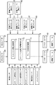
- FIG. 2 is a block diagram showing the configuration of the brake system according to this embodiment.
- the control device 70 includes a throttle opening detector 71 , a throttle rotation angular velocity detector 72 and a brake fluid pressure controller 73 .
- the control device 70 receives information from the front camera 80 and the front radar 81, as well as information from a vehicle speed sensor 90, a throttle opening sensor 91, an engine speed sensor 92, a gear position sensor 93, an acceleration sensor 94, and a gyro sensor 95. is entered.
- the gyro sensor 95 can detect the roll angle, pitch angle, and yaw angle of the vehicle body.
- the brake fluid pressure control unit 73 drives the actuators 52 and 62 based on information from various sensors to exert braking force on the front wheel brake BF and the rear wheel brake BR.
- the throttle opening Th detected by the throttle opening sensor 91 is set to a predetermined threshold value Th1 (for example, 10 degree), automatic control is started.
- FIG. 3 is a flowchart showing the procedure of automatic brake control 1 according to this embodiment.
- step S1 it is determined whether or not the operation conditions for the automatic control are satisfied, and if the determination is affirmative, the process proceeds to step S2. If a negative determination is made in step S1, the process returns to the determination in step S1.
- step S2 automatic control of the brake system is started.
- step S3 the throttle opening Th is detected.
- step S4 it is determined whether or not the throttle opening Th is less than a predetermined threshold value Th1. If an affirmative determination is made in step S4, the process proceeds to step S5 to continue automatic control of the brake system.
- step S6 it is determined whether or not the conditions for canceling the automatic control are satisfied.
- step S6 If an affirmative determination is made in step S6, the process proceeds to step S7 and the automatic control of the brake system is cancelled.
- the conditions for canceling the automatic control are set such that the vehicle speed is below a predetermined value, the operation force of the brake operator is above a predetermined value, the throttle operation amount and operation speed are above a predetermined value, and the vehicle body roll angle is above a predetermined value.
- step S4 determines whether a negative determination is made in step S4 or a negative determination is made in step S6 or a negative determination is made in step S4. If a negative determination is made in step S4, the process proceeds to step S7 without continuing the automatic control, and the series of control ends. Further, if a negative determination is made in step S6, the process returns to the determination of step S6.
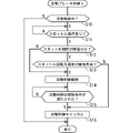
- FIG. 4 is a flowchart showing the procedure of automatic brake control 2 according to this embodiment.
- the throttle rotational angular velocity ⁇ is set to the predetermined threshold ⁇ 1 (for example, 1 degree/second). If less than ⁇ 1, the automatic control is continued.
- the throttle opening Th is equal to or greater than the predetermined threshold value Th1 and the throttle rotational angular velocity ⁇ is equal to or greater than the predetermined threshold value ⁇ 1, the automatic control of the brake system is canceled.
- the throttle rotation angular velocity ⁇ is calculated from the output of the throttle opening sensor 91 and the output of a timer provided in the control device 70 .
- step S10 it is determined whether or not the brake system is under automatic control. If an affirmative determination is made in step S10, the process proceeds to step S11, in which it is determined whether or not the throttle has been operated. If an affirmative determination is made in step S11, the process proceeds to step S12, in which it is determined whether or not the throttle opening Th is greater than or equal to a predetermined threshold value Th1. If a negative determination is made in step S10, the series of control ends.
- step S12 If an affirmative determination is made in step S12, the process proceeds to step S13, where it is determined whether or not the throttle rotation angular velocity ⁇ is less than a predetermined threshold value ⁇ 1. If an affirmative determination is made in step S13, the process proceeds to step S14 and automatic control is continued. On the other hand, if a negative determination is made in step S12, the process proceeds to step S14 to continue the automatic control.
- step S15 it is determined whether or not the conditions for canceling the automatic control are satisfied. If an affirmative determination is made in step S15, the process proceeds to step S16 and the automatic control is canceled. On the other hand, if a negative determination is made in step S15, the process returns to the determination of step S15. Further, when a negative determination is made in step S13, the process proceeds to step S16 and the automatic control is canceled.
- the control device 70 detects the operation of the throttle operator at the start of the automatic control of the front wheel brake BF and the rear wheel brake BR,
- the throttle opening Th is less than the predetermined threshold value Th1
- the automatic control is started, so when the throttle grip is unintentionally rotated by applying force to the steering handle in order to support the upper body leaning forward.
- control device 70 detects the rotation operation of the throttle operating element during the automatic control of the front wheel brake BF and the rear wheel brake BR, even if the throttle opening Th is equal to or greater than the predetermined threshold value Th1, the throttle operating element is less than the predetermined threshold value ⁇ 1, the automatic control is continued, so the brake system automatically starts decelerating, gradually applying force to the steering handle to support the upper body and throttle
- the degree of opening increases slowly, it is possible to continue automatic control of the brake system by determining that the throttle operation is not intended by the driver even when the degree of throttle opening exceeds the predetermined threshold value. As a result, it is possible to prevent the braking force from being lowered and affecting the behavior of the vehicle body.
- the control device 70 detects the turning operation of the throttle operating element during the automatic control of the front wheel brake BF and the rear wheel brake BR, the throttle opening Th is equal to or greater than the predetermined threshold value Th1, and the throttle operating element If the rotational angular velocity ⁇ is greater than or equal to the predetermined threshold ⁇ 1, the automatic control is canceled. It is possible to determine that it is an operation and release the automatic control of the brake system. This makes it possible to obtain vehicle body behavior that meets the driver's intention.
- the form of the motorcycle, the configuration of the brake system, the form of the front wheel brake operator and the rear wheel brake operator, the setting of the predetermined threshold value, etc. are not limited to the above embodiment, and various modifications are possible.
- the brake system according to the present invention can be applied not only to motorcycles, but also to saddle type three-wheeled vehicles and four-wheeled vehicles.
Landscapes
- Engineering & Computer Science (AREA)
- Transportation (AREA)
- Mechanical Engineering (AREA)
- Regulating Braking Force (AREA)
Priority Applications (3)
| Application Number | Priority Date | Filing Date | Title |
|---|---|---|---|
| US18/277,700 US20240227753A9 (en) | 2021-03-04 | 2021-12-28 | Brake system for saddled vehicle |
| JP2023503591A JP7428852B2 (ja) | 2021-03-04 | 2021-12-28 | 鞍乗型車両のブレーキシステム |
| DE112021006646.3T DE112021006646T5 (de) | 2021-03-04 | 2021-12-28 | Bremssystem für ein sattelsitzfahrzeug |
Applications Claiming Priority (2)
| Application Number | Priority Date | Filing Date | Title |
|---|---|---|---|
| JP2021034322 | 2021-03-04 | ||
| JP2021-034322 | 2021-03-04 |
Publications (1)
| Publication Number | Publication Date |
|---|---|
| WO2022185698A1 true WO2022185698A1 (ja) | 2022-09-09 |
Family
ID=83153968
Family Applications (1)
| Application Number | Title | Priority Date | Filing Date |
|---|---|---|---|
| PCT/JP2021/048777 Ceased WO2022185698A1 (ja) | 2021-03-04 | 2021-12-28 | 鞍乗型車両のブレーキシステム |
Country Status (4)
| Country | Link |
|---|---|
| US (1) | US20240227753A9 (https=) |
| JP (1) | JP7428852B2 (https=) |
| DE (1) | DE112021006646T5 (https=) |
| WO (1) | WO2022185698A1 (https=) |
Families Citing this family (5)
| Publication number | Priority date | Publication date | Assignee | Title |
|---|---|---|---|---|
| WO2022185671A1 (ja) * | 2021-03-04 | 2022-09-09 | 本田技研工業株式会社 | 鞍乗型車両のブレーキシステム |
| JP7746753B2 (ja) * | 2021-09-09 | 2025-10-01 | スズキ株式会社 | フロントフェンダ |
| JP1760840S (ja) * | 2023-05-12 | 2024-01-09 | オートバイ | |
| USD1094191S1 (en) * | 2023-09-13 | 2025-09-23 | Zhejiang CFMOTO Power Co., Ltd. | Motorcycle |
| JP1765161S (ja) * | 2023-09-13 | 2024-03-08 | オートバイ |
Citations (5)
| Publication number | Priority date | Publication date | Assignee | Title |
|---|---|---|---|---|
| JP2011194994A (ja) * | 2010-03-18 | 2011-10-06 | Honda Motor Co Ltd | 自動二輪車の制動装置 |
| WO2014016910A1 (ja) * | 2012-07-24 | 2014-01-30 | トヨタ自動車株式会社 | 運転支援装置 |
| JP2015217852A (ja) * | 2014-05-19 | 2015-12-07 | 本田技研工業株式会社 | 車両制御装置 |
| WO2016056337A1 (ja) * | 2014-10-09 | 2016-04-14 | ボッシュ株式会社 | 車両の発進を支援するための車両のブレーキ制御方法および装置 |
| JP2019073208A (ja) * | 2017-10-18 | 2019-05-16 | トヨタ自動車株式会社 | 走行支援装置 |
Family Cites Families (24)
| Publication number | Priority date | Publication date | Assignee | Title |
|---|---|---|---|---|
| DE19713715A1 (de) * | 1997-04-03 | 1998-10-08 | Itt Mfg Enterprises Inc | Automatisches Bremssystem für Kraftfahrzeuge |
| JP4434212B2 (ja) * | 2007-01-17 | 2010-03-17 | トヨタ自動車株式会社 | 車両の制御装置、制御方法、その方法を実現するプログラムおよびそのプログラムを記録した記録媒体 |
| JP4654212B2 (ja) * | 2007-03-30 | 2011-03-16 | 本田技研工業株式会社 | 駆動量制御装置 |
| JP5724569B2 (ja) * | 2011-04-15 | 2015-05-27 | トヨタ自動車株式会社 | 車両用制動制御装置 |
| JP5408201B2 (ja) * | 2011-08-10 | 2014-02-05 | 株式会社デンソー | 車両制御装置、および車両制御プログラム |
| JP5929575B2 (ja) | 2012-07-11 | 2016-06-08 | ソニー株式会社 | 消費電力管理装置及び消費電力管理システム |
| JP2014227985A (ja) * | 2013-05-27 | 2014-12-08 | アイシン精機株式会社 | 車両用駆動装置 |
| JP6136714B2 (ja) * | 2013-07-30 | 2017-05-31 | トヨタ自動車株式会社 | 車両制御装置 |
| JP6172451B2 (ja) * | 2013-08-12 | 2017-08-02 | マツダ株式会社 | 車両用制動装置 |
| JP6086107B2 (ja) * | 2014-10-17 | 2017-03-01 | トヨタ自動車株式会社 | 車両用制駆動力制御装置 |
| JP6166242B2 (ja) * | 2014-11-28 | 2017-07-19 | 株式会社アドヴィックス | 衝突回避装置 |
| JP6387939B2 (ja) * | 2015-10-16 | 2018-09-12 | トヨタ自動車株式会社 | 車両のブレーキ制御装置 |
| JP6514634B2 (ja) * | 2015-12-25 | 2019-05-15 | 株式会社デンソー | 車両制御装置及び車両制御方法 |
| JP6730890B2 (ja) * | 2016-09-14 | 2020-07-29 | 川崎重工業株式会社 | ウィリー判定装置およびウィリー判定方法 |
| JP2019026165A (ja) | 2017-08-02 | 2019-02-21 | ローベルト ボッシュ ゲゼルシャフト ミット ベシュレンクテル ハフツング | 制御装置、車体挙動制御システム、モータサイクル、及び、制御方法 |
| CN111527295B (zh) * | 2017-12-28 | 2022-07-22 | 本田技研工业株式会社 | 鞍乘型车辆 |
| JP7035753B2 (ja) * | 2018-04-16 | 2022-03-15 | トヨタ自動車株式会社 | 運転支援装置 |
| JP2020147108A (ja) * | 2019-03-12 | 2020-09-17 | 本田技研工業株式会社 | 鞍乗型車両のパーキングブレーキ装置 |
| DE102019209864A1 (de) * | 2019-07-04 | 2021-01-07 | Robert Bosch Gmbh | Verfahren und Vorrichtung zur Durchführung einer autonomen Bremsung bei einem einspurigen Kraftfahrzeug |
| JP7140077B2 (ja) * | 2019-09-02 | 2022-09-21 | トヨタ自動車株式会社 | 衝突回避支援装置 |
| DE102020204081A1 (de) * | 2019-11-14 | 2021-05-20 | Robert Bosch Gesellschaft mit beschränkter Haftung | Verfahren zum Betreiben eines fahrpedalgesteuerten Abstandsreglers eines Fahrzeugs und Steuergerät |
| JP7572148B2 (ja) * | 2020-01-09 | 2024-10-23 | トヨタ自動車株式会社 | 運転支援装置 |
| WO2022185672A1 (ja) * | 2021-03-04 | 2022-09-09 | 本田技研工業株式会社 | 鞍乗型車両のブレーキシステム |
| WO2022185671A1 (ja) * | 2021-03-04 | 2022-09-09 | 本田技研工業株式会社 | 鞍乗型車両のブレーキシステム |
-
2021
- 2021-12-28 JP JP2023503591A patent/JP7428852B2/ja active Active
- 2021-12-28 WO PCT/JP2021/048777 patent/WO2022185698A1/ja not_active Ceased
- 2021-12-28 DE DE112021006646.3T patent/DE112021006646T5/de active Pending
- 2021-12-28 US US18/277,700 patent/US20240227753A9/en active Pending
Patent Citations (5)
| Publication number | Priority date | Publication date | Assignee | Title |
|---|---|---|---|---|
| JP2011194994A (ja) * | 2010-03-18 | 2011-10-06 | Honda Motor Co Ltd | 自動二輪車の制動装置 |
| WO2014016910A1 (ja) * | 2012-07-24 | 2014-01-30 | トヨタ自動車株式会社 | 運転支援装置 |
| JP2015217852A (ja) * | 2014-05-19 | 2015-12-07 | 本田技研工業株式会社 | 車両制御装置 |
| WO2016056337A1 (ja) * | 2014-10-09 | 2016-04-14 | ボッシュ株式会社 | 車両の発進を支援するための車両のブレーキ制御方法および装置 |
| JP2019073208A (ja) * | 2017-10-18 | 2019-05-16 | トヨタ自動車株式会社 | 走行支援装置 |
Also Published As
| Publication number | Publication date |
|---|---|
| DE112021006646T5 (de) | 2023-10-19 |
| US20240227753A9 (en) | 2024-07-11 |
| JP7428852B2 (ja) | 2024-02-06 |
| US20240132029A1 (en) | 2024-04-25 |
| JPWO2022185698A1 (https=) | 2022-09-09 |
Similar Documents
| Publication | Publication Date | Title |
|---|---|---|
| JP7428852B2 (ja) | 鞍乗型車両のブレーキシステム | |
| JP7142635B2 (ja) | 制御装置、車体挙動制御システム、モータサイクル、及び、制御方法 | |
| JPWO2022185698A5 (https=) | ||
| JP2016068769A (ja) | 鞍乗り型車両 | |
| US9132771B2 (en) | Turn signal canceling device for a laterally tilting vehicle | |
| JP6833667B2 (ja) | 車両 | |
| JP7554903B2 (ja) | 鞍乗型車両のブレーキシステム | |
| JP2020100229A (ja) | 鞍乗型車両のライダー支援システムのための処理装置及び処理方法、鞍乗型車両のライダー支援システム、及び、鞍乗型車両 | |
| TWI604978B (zh) | 驅動轉矩控制裝置、驅動源單元及車輛 | |
| JP7430475B2 (ja) | 鞍乗型車両のブレーキシステム | |
| JP6178583B2 (ja) | 直進旋回判定装置 | |
| JP7284283B2 (ja) | 鞍乗型車両の車両情報報知装置 | |
| WO2024203085A1 (ja) | 車両制御システム、及び鞍乗型車両 | |
| JP4247052B2 (ja) | 車両における操作装置 | |
| US20220306101A1 (en) | Automatic control device for motorcycle | |
| JP7197552B2 (ja) | 車両 | |
| WO2022195997A1 (ja) | 鞍乗型車両 | |
| US12466372B2 (en) | Saddled vehicle | |
| US20240400014A1 (en) | Control device for motorcycle | |
| JP2010076658A (ja) | 鞍乗型車両の制動装置 | |
| JP7197551B2 (ja) | 車両 | |
| JP2014190164A (ja) | 自動二輪車の制御装置 | |
| WO2022195999A1 (ja) | 自動二輪車の自動吹鳴装置 | |
| WO2026069640A1 (ja) | 車両制御装置 | |
| WO2023191105A1 (ja) | 鞍乗型車両 |
Legal Events
| Date | Code | Title | Description |
|---|---|---|---|
| 121 | Ep: the epo has been informed by wipo that ep was designated in this application |
Ref document number: 21929254 Country of ref document: EP Kind code of ref document: A1 |
|
| DPE2 | Request for preliminary examination filed before expiration of 19th month from priority date (pct application filed from 20040101) | ||
| ENP | Entry into the national phase |
Ref document number: 2023503591 Country of ref document: JP Kind code of ref document: A |
|
| WWE | Wipo information: entry into national phase |
Ref document number: 18277700 Country of ref document: US |
|
| WWE | Wipo information: entry into national phase |
Ref document number: 112021006646 Country of ref document: DE |
|
| 122 | Ep: pct application non-entry in european phase |
Ref document number: 21929254 Country of ref document: EP Kind code of ref document: A1 |