WO2021256271A1 - 配線モジュール及び弾性止水部材 - Google Patents
配線モジュール及び弾性止水部材 Download PDFInfo
- Publication number
- WO2021256271A1 WO2021256271A1 PCT/JP2021/021130 JP2021021130W WO2021256271A1 WO 2021256271 A1 WO2021256271 A1 WO 2021256271A1 JP 2021021130 W JP2021021130 W JP 2021021130W WO 2021256271 A1 WO2021256271 A1 WO 2021256271A1
- Authority
- WO
- WIPO (PCT)
- Prior art keywords
- wiring
- slit
- accommodating
- penetration
- water blocking
- Prior art date
- Legal status (The legal status is an assumption and is not a legal conclusion. Google has not performed a legal analysis and makes no representation as to the accuracy of the status listed.)
- Ceased
Links
Images




Classifications
-
- H—ELECTRICITY
- H01—ELECTRIC ELEMENTS
- H01B—CABLES; CONDUCTORS; INSULATORS; SELECTION OF MATERIALS FOR THEIR CONDUCTIVE, INSULATING OR DIELECTRIC PROPERTIES
- H01B17/00—Insulators or insulating bodies characterised by their form
- H01B17/56—Insulating bodies
- H01B17/58—Tubes, sleeves, beads, or bobbins through which the conductor passes
-
- H—ELECTRICITY
- H01—ELECTRIC ELEMENTS
- H01B—CABLES; CONDUCTORS; INSULATORS; SELECTION OF MATERIALS FOR THEIR CONDUCTIVE, INSULATING OR DIELECTRIC PROPERTIES
- H01B7/00—Insulated conductors or cables characterised by their form
- H01B7/17—Protection against damage caused by external factors, e.g. sheaths or armouring
- H01B7/28—Protection against damage caused by moisture, corrosion, chemical attack or weather
- H01B7/282—Preventing penetration of fluid, e.g. water or humidity, into conductor or cable
-
- H—ELECTRICITY
- H02—GENERATION; CONVERSION OR DISTRIBUTION OF ELECTRIC POWER
- H02G—INSTALLATION OF ELECTRIC CABLES OR LINES, OR OF COMBINED OPTICAL AND ELECTRIC CABLES OR LINES
- H02G15/00—Cable fittings
- H02G15/013—Sealing means for cable inlets
-
- H—ELECTRICITY
- H02—GENERATION; CONVERSION OR DISTRIBUTION OF ELECTRIC POWER
- H02G—INSTALLATION OF ELECTRIC CABLES OR LINES, OR OF COMBINED OPTICAL AND ELECTRIC CABLES OR LINES
- H02G15/00—Cable fittings
- H02G15/02—Cable terminations
- H02G15/04—Cable-end sealings
-
- H—ELECTRICITY
- H02—GENERATION; CONVERSION OR DISTRIBUTION OF ELECTRIC POWER
- H02G—INSTALLATION OF ELECTRIC CABLES OR LINES, OR OF COMBINED OPTICAL AND ELECTRIC CABLES OR LINES
- H02G15/00—Cable fittings
- H02G15/02—Cable terminations
- H02G15/06—Cable terminating boxes, frames or other structures
Definitions
- This disclosure relates to a wiring module and an elastic waterproof member.
- Patent Document 1 discloses a rubber stopper applied to a multi-core cable.
- the rubber stopper has a sheath outer fitting that is fitted to the end of the sheath in a multi-core cable, and has a plurality of through holes through which each of the plurality of wires derived from the end of the sheath is penetrated. It is configured to have a part.
- Patent Document 1 in order to suppress the intrusion of water through the multi-core cable, a configuration is adopted in which the electric wire penetrates through the through hole of the rubber stopper.
- the wiring member can be easily penetrated into the through hole of the elastic water blocking member.
- the wiring module of the present disclosure includes a wiring member and an elastic waterproof member having a penetration accommodating portion capable of accommodating a part of the wiring member in the longitudinal direction, and the elastic waterproof member thereof. Wiring in which a slit from the outer peripheral portion to the penetration accommodating portion is formed, and the slit is kept closed in a state where a part of the wiring member in the longitudinal direction is accommodated in the penetration accommodating portion. It is a module.
- the elastic water-stopping member of the present disclosure is an elastic water-stopping member mounted on a wiring member, and a penetration accommodating portion capable of accommodating a part of the wiring member in the longitudinal direction is formed from the outer peripheral portion. It is an elastic waterproof member having a slit leading to the penetration accommodating portion.
- the elastic waterproof member can be easily attached to the wiring member.
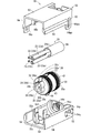
- FIG. 1 is a perspective view showing a wiring module.
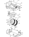
- FIG. 2 is an exploded perspective view showing a wiring module.
- FIG. 3 is an exploded perspective view showing a wiring module.
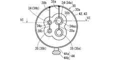
- FIG. 4 is a plan view showing an elastic water blocking member.
- FIG. 5 is a front view showing an elastic water blocking member.
- FIG. 6 is a sectional view taken along line VI-VI of FIG.
- FIG. 7 is a sectional view taken along line VII-VII of FIG.
- FIG. 8 is a perspective view showing a state in which the elastic waterproof member is set on the first exterior member.
- the wiring module of this disclosure is as follows.
- a wiring member and an elastic water-stopping member having a penetration accommodating portion capable of accommodating a part of the wiring member in the longitudinal direction are provided, and the elastic water-stopping member is provided with the elastic water-stopping member from the outer peripheral portion thereof.
- the wiring member includes a plurality of linear wiring members and a covering member covering the plurality of linear wiring members, and the plurality of wiring members from the end portion of the covering member.
- the linear wiring member of the above extends, and the penetration accommodating portion includes a covering member accommodating recess covering an end portion of the covering member, and a plurality of penetrating portions continuous with the covering member accommodating recess.
- Penetration portions are provided corresponding to the plurality of linear wiring members, and the slits are a base slit portion extending from the outer peripheral portion of the elastic water blocking member to the covering member accommodating recess, and a plurality of slits from the base slit portion.
- each of the end portion of the covering member and the plurality of linear wiring members can be accommodated in the covering member accommodating recess and the plurality of penetrating portions via the slits to stop water.
- the wiring member includes a linear wiring member and a back-side linear wiring member, and the penetration accommodating portion is among the linear wiring members.
- the slit includes a penetrating portion capable of accommodating a part in the longitudinal direction and a penetrating portion on the back side capable of accommodating a part in the longitudinal direction of the back-side linear wiring member, and the slit is an outer periphery of the elastic water blocking member.
- An inner slit may be formed in a portion extending from the portion to the penetrating portion, and the elastic water blocking member may be formed with an inner slit extending from the penetrating portion to the inner penetrating portion. Since the back slit from the penetrating portion to the back penetrating portion is formed, the number of slits leading to the outer peripheral portion of the elastic water blocking member can be reduced. Thereby, the water stopping property can be enhanced.
- the elastic waterproof member may be accommodated in a state where the second exterior member is united and the slit is closed between the first exterior member and the second exterior member. By accommodating the elastic waterproof member in the exterior member, the slit is kept in a closed state.
- the elastic waterproof member is a first exterior member in a state where the outward portion of the slit in the outer peripheral portion thereof is exposed to the outside from the first exterior member. It may be set to. As a result, with the elastic water blocking member set in the first exterior member, a part of the wiring member in the longitudinal direction can be accommodated in the penetration accommodating portion through the slit. Therefore, the elastic water stop member is easily attached to the wiring member in a state where the elastic water stop member is easily held together with the first exterior member.
- the exterior member exerts a tightening force in a direction of closing the slit in a state where the first exterior member and the second exterior member are united. It may be something to make. As a result, the slit is closed more reliably, and the water stopping property is improved.
- the elastic waterproof member of the present disclosure is as follows.
- An elastic waterproof member mounted on the wiring member in which a penetration accommodating portion capable of accommodating a part of the wiring member in the longitudinal direction is formed, and a slit from the outer peripheral portion to the penetration accommodating portion is formed. It is an elastic waterproof member formed. According to the present disclosure, a portion of the wiring member in the longitudinal direction is easily accommodated in the penetration accommodating portion through a slit. Therefore, the elastic water blocking member is easily attached to the wiring member.
- the penetration accommodating portion includes a covering member accommodating recess opening on one side and a plurality of penetrating portions continuous with the inner side of the covering member accommodating recess.
- the slits are divided into a base slit portion extending from the outer peripheral portion of the elastic waterproof member to the covering member accommodating recess, and a plurality of the base slit portions, and the plurality of penetrating portions from the outer peripheral portion of the elastic waterproof member. It may include a plurality of individual slit portions leading to each. As a result, water can be stopped individually for each of the end portion of the covering member and the plurality of linear wiring members.
- the slit includes a back-side penetrating portion capable of accommodating a part of the linear wiring member in the longitudinal direction different from the linear wiring member in the above, and the slit extends from the outer peripheral portion of the elastic water blocking member to the penetrating portion.
- a back slit formed in the portion and extending from the penetrating portion to the back penetrating portion may be further formed. Since the back slit from the penetrating portion to the back penetrating portion is formed, the number of slits leading to the outer peripheral portion of the elastic water blocking member can be reduced. Thereby, the water stopping property can be enhanced.
- FIG. 1 is a perspective view showing a wiring module 10.
- 2 and 3 are exploded perspective views showing the wiring module 10.
- FIG. 2 is a perspective view from the second exterior member 62 side
- FIG. 3 is a perspective view seen from the first exterior member 52. A part of the wiring member 20 is shown in each figure.
- the wiring module 10 includes a wiring member 20 and an elastic waterproof member 30.
- the wiring module 10 further includes an exterior member 50.
- the wiring member 20 penetrates the elastic water blocking member 30.
- the elastic water blocking member 30 suppresses the intrusion of water that has traveled around the wiring member 20.
- the elastic water blocking member 30 is housed in the exterior member 50. As a result, the state in which the wiring member 20 penetrates the elastic water blocking member 30 is maintained.
- the wiring member 20 includes the linear wiring member 22.
- the wiring member 20 may include one linear wiring member 22 or may include a plurality of linear wiring members 22. In this embodiment, an example in which the wiring member 20 includes a plurality of (here, two) linear wiring members 22 will be described.
- the wiring member 20 further includes a back-side linear wiring member 23.
- the wiring member 20 includes a plurality of (here, two) back-side linear wiring members 23.
- the linear wiring member 22 and the back-side linear wiring member 23 may be provided one by one.
- the back-side linear wiring member 23 may be omitted.
- the linear wiring member 22 and the back-side linear wiring member 23 are linear media for transmitting electricity, and are, for example, electric wires having a core wire and a coating covering the periphery of the core wire.
- the linear wiring member and the back-side linear wiring member 23 may be a cable in which a plurality of electric wires are covered with a sheath.
- the linear wiring member and the back-side linear wiring member may have an electromagnetic shield layer such as a braid.
- the linear wiring member and the back-side linear wiring member may be a coaxial cable in which the circumference of the inner conductor is covered with an outer conductor, and the circumference thereof is further covered with a sheath.
- the linear wiring member and the back-side linear wiring member may be a signal line or a power supply line.
- the plurality of linear wiring members 22 include linear wiring members having different thicknesses from each other. In the following description, for convenience of explanation, they may be distinguished as a thicker linear wiring member 22a and a thinner linear wiring member 22b.
- the plurality of back-side linear wiring members 23 include back-side linear wiring members having different thicknesses from each other. In the following description, for convenience of explanation, they may be distinguished as a thicker back-side linear wiring member 23a and a thinner back-side linear wiring member 23b.
- the thicker linear wiring member 22a and the thicker back-side linear wiring member 23a have the same thickness.
- the thinner linear wiring member 22b and the thinner inner linear wiring member 23b have the same thickness.
- the thickness of each linear wiring member and each back-side linear wiring member is arbitrary.
- the wiring member 20 includes a covering member 24 that covers a part of the plurality of linear wiring members 22 in the extending direction.
- the covering member 24 further covers a part of the plurality of back-side linear wiring members 23 in the extending direction.
- the covering member 24 is, for example, a sheath formed by extruding and coating a softened and melted resin around the linear wiring member 22 and the back-side linear wiring member 23.
- the covering member 24 may partially cover a part of the linear wiring member 22 and the back-side linear wiring member 23 in the extending direction.
- the covering member 24 may be an adhesive tape spirally wound so as to overlap the linear wiring member 22 and the back-side linear wiring member 23.
- the covering member 24 may be a corrugated tube, a resin tube, a resin sheet, or the like externally attached to the linear wiring member 22 and the back-side linear wiring member 23.
- the portion of the linear wiring member 22 and the back-side linear wiring member 23 covered by the covering member 24 is kept bundled by the covering member 24.
- a plurality of linear wiring members 22 extend from the end of the covering member 24.
- the back-side linear wiring member 23 also extends from the end of the covering member 24.
- the two linear wiring members 22a and 22b extend from the end of the covering member 24, and the two back-side linear wiring members 23a and 23b extend.
- FIG. 4 is a plan view showing the elastic waterproof member 30.
- FIG. 5 is a front view showing the elastic water blocking member 30.
- FIG. 6 is a sectional view taken along line VI-VI of FIG.
- FIG. 7 is a sectional view taken along line VII-VII of FIG.
- the exterior member 50 is shown by a two-dot chain line.
- a cross section of the wiring member 20 housed in the penetration accommodating portion 32 is shown, and the exterior member 50 is shown by a two-dot chain line.
- the elastic waterproof member 30 is a member formed of an elastic material such as silicone rubber.
- the elastic water blocking member 30 is formed in a columnar shape. More specifically, the elastic water blocking member 30 includes a columnar portion 30a and an extension portion 30b. An extension portion 30b is formed on a portion on the side where the linear wiring member 22 and the back side linear wiring member 23 extend with respect to the columnar portion 30a. The extension portion 30b is thinner than the columnar portion 30a.
- the cross section of the columnar portion 30a (the cross section in the plane orthogonal to the axis) is circular, and the outer edge of the cross section of the extension portion 30b is formed in a shape in which the outer edges of the four circles are connected. ..
- the partial circumference that defines the outer peripheral surface of the extension portion 30b is formed concentrically with the penetration portion 34 and the back penetration portion 35, which will be described later.
- the elastic water blocking member 30 may also be formed in an elliptical columnar shape or a square cylinder shape.
- a penetration accommodating portion 32 is formed in the elastic water blocking member 30 (see FIG. 6). The penetration accommodating portion 32 penetrates along the axial direction of the elastic water blocking member 30. The penetration accommodating portion 32 is formed so as to accommodate a part of the wiring member 20 in the longitudinal direction.
- the end portion 24a of the covering member 24 of the wiring member 20 and the portion of the linear wiring member 22 and the back-side linear wiring member 23 extending from the end portion 24a of the covering member 24 are elastically stopped. It is housed in the water member 30.
- the penetration accommodating portion 32 includes a covering member accommodating recess 33 and a plurality of penetration accommodating portions 34.
- the penetration accommodating portion 32 includes a plurality of inner penetration portions 35.
- the covering member accommodating recess 33 is formed in a shape that covers the end portion 24a of the covering member 24. More specifically, the covering member accommodating recess 33 is formed in a columnar space recessed from one end in the axial direction of the elastic water blocking member 30. An annular protrusion 33p protruding toward the inner peripheral side is formed in the inner peripheral portion of the covering member accommodating recess 33 (see FIG. 6). The annular protrusion 33p is a portion sometimes called a lip. The inner diameter of the annular protrusion 33p is formed to be smaller than the outer diameter of the covering member 24.
- a plurality (three) of the annular protrusions 33p are formed so as to be dispersed in the axial direction of the covering member accommodating recesses 33.
- the tip end portion of the annular protrusion 33p is elastically deformed and adheres to the periphery of the end portion 24a. As a result, water is suppressed from flowing around the outer periphery of the covering member 24.
- the plurality of through portions 34 are through holes provided continuously with the covering member accommodating recess 33.
- the plurality of penetration portions 34 are holes that penetrate from the bottom of the covering member accommodating recess 33 toward the other end of the elastic water blocking member 30.
- the plurality of penetrating portions 34 are provided corresponding to the plurality of linear wiring members 22.
- two of the plurality of penetrating portions 34 are provided in parallel corresponding to the two linear wiring members 22.
- the one corresponding to the thicker linear wiring member 22a may be referred to as a penetrating portion 34a
- the one corresponding to the thinner linear wiring member 22b may be referred to as a penetrating portion 34b.
- the penetrating portion 34a is larger than the penetrating portion 34b.
- annular protrusion 34ap protruding toward the inner peripheral side is formed in the inner peripheral portion of the penetrating portion 34a.
- the annular protrusion 34ap is a portion sometimes called a lip.
- the inner diameter of the annular protrusion 34ap is formed to be smaller than the outer diameter of the linear wiring member 22a.
- a plurality of annular protrusions 34ap are formed so as to be dispersed in the axial direction of the penetration portions 34a.
- annular protrusion 34bp protruding toward the inner peripheral side is formed in the inner peripheral portion of the penetrating portion 34b.
- the annular protrusion 34bp is a portion sometimes called a lip.
- the inner diameter of the annular protrusion 34bp is formed to be smaller than the outer diameter of the linear wiring member 22b.
- a plurality of annular protrusions 34bp are formed so as to be dispersed in the axial direction of the penetration portions 34b.
- the back-side penetrating portion 35 is a through-hole provided continuously with the covering member accommodating recess 33.
- the plurality (two) inner penetration portions 35 are holes that penetrate from the bottom of the covering member accommodating recess 33 toward the other end of the elastic water blocking member 30.
- the plurality of back-side penetrating portions 35 are provided corresponding to the plurality of back-side linear wiring members 23.
- two back-side penetrating portions 35 are provided in parallel corresponding to the two back-side linear wiring members 23.
- the one corresponding to the thicker back-side linear wiring member 23a may be referred to as the back-side penetrating portion 35a
- the one corresponding to the thinner back-side linear wiring member 23b may be referred to as the back-side penetrating portion 35b.
- the back-side penetrating portion 35a is larger than the back-side penetrating portion 35b.
- the back-side penetrating portion 35a has the same shape as the penetrating portion 34a.
- the back-side penetrating portion 35b has the same shape as the penetrating portion 34b.
- the thicker inner penetrating portion 35a is provided next to the thicker penetrating portion 34a.
- the narrower inner penetrating portion 35b is provided next to the narrower penetrating portion 34b. Therefore, the thicker penetrating portion 34a and the thicker inner penetrating portion 35a are provided unevenly on one side of the elastic water blocking member 30, and the thinner penetrating portion 34b and the thinner inner penetrating portion 35b are elastic. It is provided unevenly on the other side of the water blocking member 30.
- the thicker linear wiring member 22a and the thicker back-side linear wiring member 23a are placed in the penetrating portion 34a and the back-side penetrating portion 35a. It is housed in a penetrating state. Further, the narrower linear wiring member 22b and the narrower back-side linear wiring member 23b are housed in a state of penetrating the penetrating portion 34b and the back-side penetrating portion 35b. In this state, of the end portion 24a of the covering member 24, the linear wiring member 22, and the back-side linear wiring member 23, the portion closer to the covering member 24 is stopped by the elastic water blocking member 30.
- the opening of the end portion 24a of the covering member 24 includes a water stop portion of the end portion 24a of the covering member 24 (particularly, a water stop portion due to the covering member accommodating recess 33), the linear wiring member 22, and the backside linear wiring member 23.
- the portion closer to the covering member 24 is located inside the water stop portion (particularly, the water stop portion due to the penetrating portions 34a, 34b and the inner penetrating portions 35a, 35b, etc.). Therefore, the intrusion of water from the opening of the end portion 24a of the covering member 24 is also suppressed.
- a slit 36 is formed in the elastic water blocking member 30 from the outer peripheral portion thereof to the penetration accommodating portion 32.
- the slit 36 is formed so as to cover the entire extending direction of the penetration accommodating portion 32. Therefore, a part of the wiring member 20 in the longitudinal direction can be accommodated in the penetration accommodating portion 32 through the slit 36.
- the slit 36 includes a base slit portion 37 and a plurality of individual slit portions 38a and 38b.
- the base slit portion 37 is a slit extending from the outer peripheral portion of the elastic waterproof member 30 to the covering member accommodating recess 33. More specifically, the base slit portion 37 is formed in a portion of the elastic waterproof member 30 near one end. The base slit portion 37 is formed so as to face the covering member accommodating recess 33 from the outer peripheral portion of the elastic waterproof member 30 and to follow the direction parallel to the central axis of the elastic waterproof member 30.
- the plurality of individual slit portions 38a and 38b extend from the base slit portion 37 in a Y shape.
- the plurality of individual slit portions 38a and 38b are formed so as to extend from the outer peripheral portion of the elastic water blocking member 30 to the plurality of (here, two) penetrating portions 34a and 34b.
- the individual slit portion 38a includes a slit portion extending from the outer peripheral portion of the elastic waterproof member 30 toward the penetrating portion 34a and along a direction parallel to the central axis of the elastic waterproof member 30.
- the individual slit portion 38b includes a slit portion that faces the penetrating portion 34b from the outer peripheral portion of the elastic waterproof member 30 and is along a direction parallel to the central axis of the elastic waterproof member 30.
- the individual slit portions 38a and 38b and the base slit portion 37 are connected in a Y shape when viewed from the outside of the elastic water blocking member 30.
- the elastic water blocking member 30 is formed with back slits 39a and 39b extending from the penetrating portions 34a and 34b to the back penetrating portions 35a and 35b.
- a back slit 39a is formed from the penetrating portion 34a toward the back penetrating portion 35a and along a direction parallel to the axial direction of the elastic water blocking member 30.
- a back slit 39b is formed from the penetrating portion 34b toward the back penetrating portion 35b and along a direction parallel to the axial direction of the elastic water blocking member 30.
- the end portion 24a of the covering member 24 is accommodated in the covering member accommodating recess 33 via the base slit portion 37.
- the thicker back-side linear wiring member 23a is housed in the back-side penetrating portion 35a from the individual slit portion 38a via the through-side portion 34a and further, the back-side slit 39a.
- the narrower back-side linear wiring member 23b is housed in the back-side penetrating portion 35b from the individual slit portion 38b to the through-side portion 34b and further via the back-side slit 39b.
- the thicker linear wiring member 22a is housed in the penetrating portion 34a via the individual slit portion 38a.
- the narrower linear wiring member 22b is housed in the penetrating portion 34b via the individual slit portion 38b.
- the elastic water blocking member 30 is attached to a part of the wiring member 20 in the longitudinal direction.
- a first outer annular protrusion 42 and a second outer annular protrusion 43 are formed on the outer peripheral portion of the elastic water blocking member 30.
- the first outer annular protrusion 42 is formed on the outer side of the covering member accommodating recess 33 in the outer peripheral portion of the elastic water blocking member 30. It is preferable that the first outer annular protrusion 42 and the annular protrusion 33p are provided at least partially overlapping each other in the axial direction of the elastic water blocking member 30.
- the first outer annular protrusion 42 is formed in an annular shape that protrudes along the circumferential direction from the outer peripheral side portion of the columnar portion 30a of the elastic water blocking member 30. Here, a plurality of first outer annular protrusions 42 are formed.
- the second outer annular protrusion 43 is formed on the outer peripheral side portions of the penetrating portions 34a and 34b and the inner penetrating portions 35a and 35b in the outer peripheral portion of the elastic water blocking member 30. It is preferable that the second outer annular protrusion 43 and the annular protrusions 34ap and 34bp are provided at least partially overlapping in the axial direction of the elastic water blocking member 30.
- the second outer annular protrusion 43 is formed in an annular shape that protrudes along the circumferential direction from the outer peripheral portion of the columnar portion 30a of the elastic water blocking member 30. Here, a plurality of second outer annular protrusions 43 are formed.
- a set protrusion 44 is formed in a portion of the outer peripheral portion of the elastic waterproof member 30 opposite to the portion where the slit 36 is formed.
- the set protrusion 44 includes a base portion 44a and a head portion 44b.
- the base portion 44a protrudes from the outer peripheral portion of the elastic waterproof member 30.
- the head portion 44b projects from the tip end portion of the base portion 44a toward the outer peripheral side of the base portion 44a.
- the head 44b is formed in a shape other than a circle, for example, an oval shape.
- the head 44b is fitted into the set recess 57 in the exterior member 50.
- the slit 36 is kept closed with a part of the wiring member 20 in the longitudinal direction accommodated in the penetration accommodating portion 32.
- the slit 36 is kept closed by the exterior member 50.
- the exterior member 50 is a member that can cover the circumference of the elastic waterproof member 30 and keep the slit 36 in a closed state.
- the exterior member 50 includes a first exterior member 52 that can be combined with each other and a second exterior member 62. In a state where the first exterior member 52 and the second exterior member 62 are united, the elastic water blocking member 30 is accommodated between them. The force that tries to keep the first exterior member 52 and the second exterior member 62 in a united state compresses the elastic water blocking member 30, whereby the slit 36 is kept in a closed state.
- first exterior member 52 and the second exterior member 62 are members formed of resin or the like, respectively.
- the first exterior member 52 includes a bottom plate portion 53 and a pair of side wall portions 54.
- the bottom plate portion 53 is formed in the shape of a square plate.
- a pair of side wall portions 54 are erected on both side portions of the bottom plate portion 53.
- a protrusion 54p for coalescence is formed on the outer surface of the side wall portion 54.
- the coalescence protrusion 54p is formed in a shape in which the protrusion dimension gradually decreases toward the tip end side of the side wall portion 54.
- Guide protrusions 54q are formed on both sides of the coalescence protrusions 54p.
- the guide protrusion 54q is formed in an elongated protrusion shape from the base end side to the tip end side of the side wall portion 54.
- a semicircular surface-shaped water blocking member split holding surface 55f is formed in the middle portion in the longitudinal direction of the bottom plate portion 53.
- Half of the columnar portion 30a of the elastic waterproof member 30 is housed in the split holding surface 55f of the waterproof member.
- a first positioning portion 55a is provided at one end of the water blocking member split holding surface 55f.
- the first positioning portion 55a is formed in a U shape that protrudes inward from the inner peripheral surface of the water blocking member split holding surface 55f.
- a recess in which the covering member 24 can be placed is formed in the first positioning portion 55a.
- a semi-cylindrical holding portion 56a capable of accommodating the covering member 24 is formed at one end of the bottom plate portion 53.
- the semi-cylindrical holding portion 56a is located outside the first positioning portion 55a.
- a protrusion along the circumferential direction is formed on the inner peripheral surface of the semi-cylindrical holding portion 56a.
- the portion of the covering member 24 of the wiring member 20 extending from the elastic water blocking member 30 is held in the semi-cylindrical holding portion 56a through the first positioning portion 55a.
- a second positioning portion 55b is provided at the other end of the water blocking member split holding surface 55f.
- the second positioning portion 55b is formed in a U shape that protrudes inward from the inner peripheral surface of the water blocking member split holding surface 55f.
- a recess in which the extension portion 30b of the elastic water blocking member 30 can be arranged is formed in the second positioning portion 55b.
- a partition portion 55c that passes through a position intermediate in the width direction of the second positioning portion 55b is projected from the outer portion of the bottom plate portion 53 of the second positioning portion 55b.
- the thicker linear wiring member 22a, the thicker back-side linear wiring member 23a, and the thinner linear wiring member extend outward while being partitioned by the partition portion 55c.
- a set recess 57 is formed on the water blocking member split holding surface 55f of the bottom plate portion 53.
- the set recess 57 is formed in a shape into which the set protrusion 44 can be fitted.
- the set recess 57 is formed in an oval shape corresponding to the set protrusion 44.
- the set recess 57 may be recessed when viewed from the water blocking member split holding surface 55f, and may be a bottomed hole or a penetrating hole.
- the set recess 57 is a hole that penetrates outward from the water blocking member split holding surface 55f.
- the elastic water stop member 30 is set on the water stop member split holding surface 55f in a state where the set protrusion 44 is fitted in the set recess 57. In this state, about half of the elastic water stop member 30 on the set protrusion 44 side is housed in the water stop member split holding surface 55f. In this state, one end surface of the elastic water blocking member 30 comes into contact with the first positioning portion 55a. Further, the extension portion 30b of the elastic water stop member 30 is housed in the second positioning portion 55b, and the outward step portion at the boundary between the columnar portion 30a and the extension portion 30b of the elastic water stop member 30 is the second. It is in contact with the positioning portion 55b.
- the elastic water blocking member 30 is positioned in the axial direction with respect to the first exterior member 52.
- the slit 36 is formed in a portion of the elastic water blocking member 30 opposite to the set protrusion 44. Therefore, the outward portion of the slit 36 in the outer peripheral portion of the elastic waterproof member 30 is in a state of being exposed to the outside on the side opposite to the bottom plate portion 53. Therefore, for the elastic waterproof member 30 set in the first exterior member 52, a part of the wiring member 20 can be accommodated in the penetration accommodating portion 32 of the elastic waterproof member 30 through the slit 36.
- the second exterior member 62 includes a ceiling plate portion 63 and a pair of side wall portions 64.
- the ceiling plate portion 63 is formed in the same square plate shape as the bottom plate portion 53.
- a pair of side wall portions 64 project from both side portions of the ceiling plate portion 63.
- a concave portion 64pa for union is formed on the outer surface of the side wall portion 64.
- an extension piece 64p for coalescence is formed from the outer surface of the side wall portion 64 toward the tip end side thereof. At the tip of the coalescing extension piece 64p, a coalescing recess 64pa on which the coalescing protrusion 54p can be placed is formed.
- the tip edges of the pair of side wall portions 54 and the tip edges of the pair of side wall portions 64 are arranged to face each other.
- the overlapping piece of the tip portion of the pair of side wall portions 64 covers the outside of the tip edge of the pair of side wall portions 54.
- the tip of the union extension piece 64p gets over the union protrusion 54p, and the union protrusion 54p enters the union recess 64pa.
- the coalescing protrusion 54p is caught in the coalescing recess 64pa in a retaining state, and the coalesced state of the first exterior member 52 and the second exterior member 62 is maintained.
- a semicircular surface-shaped water blocking member split holding surface 65f is formed in the middle portion in the longitudinal direction of the ceiling plate portion 63.
- Half of the columnar portion 30a of the elastic waterproof member 30 is housed in the split holding surface 65f of the waterproof member.
- the columnar portion 30a of the elastic water blocking member 30 is housed in the columnar space formed by the water blocking member split holding surface 55f and the water blocking member split holding surface 65f.
- the distance between the inner portion of the water blocking member split holding surface 55f and the inner portion of the water blocking member divided holding surface 65f is the first in the columnar portion 30a. It is smaller than the diameter of the outer annular protrusion 42 and the second outer annular protrusion 43. Further, the radius of curvature of the water blocking member split holding surfaces 55f and 65f is smaller than the radius of the first outer annular protrusion 42 and the second outer annular protrusion 43 in the columnar portion 30a.
- a first positioning portion 65a is provided at one end of the water blocking member split holding surface 65f.
- the first positioning portion 65a is formed in an arc shape protruding inward from the inner peripheral surface of the water blocking member split holding surface 65f.
- the first positioning portions 55a and 65a come into contact with the annular region of one end surface of the elastic water stop member 30 to position the elastic water stop member 30. conduct.
- a semi-cylindrical holding portion 66a having the same configuration as the semi-cylindrical holding portion 56a is formed at one end of the ceiling plate portion 63. In a state where the first exterior member 52 and the second exterior member 62 are united, the semi-cylindrical holding portions 56a and 66a sandwich and hold the covering member 24.
- a partition wall portion 65b is provided at the other end of the water blocking member split holding surface 65f.
- the partition wall portion 65b is formed with a recess in which the second positioning portion 55b and the extension portion 30b can be arranged.
- the second positioning portion 55b and the extension portion 30b are arranged in the recess of the partition wall portion 65b in a state where the first exterior member 52 and the second exterior member 62 are united. In this state, the partition wall portion 65b partitions the inner and outer spaces of the exterior member 50.
- the elastic water blocking member 30 is set in the first exterior member 52 so that the set protrusion 44 is fitted into the set recess 57.
- the portion of the elastic water blocking member 30 in which the slit 36 is formed faces the opposite side with respect to the bottom plate portion 53. Therefore, the outer opening of the slit 36 is exposed on the side opposite to the bottom plate portion 53.
- About half of the elastic water stop member 30 on the set protrusion 44 side is housed in the water stop member split holding surface 55f of the first exterior member 52, and the portion on the opposite side is exposed to the outside. There is. Therefore, the elastic water blocking member 30 can be elastically deformed so as to widen the slit 36.
- the end portion 24a of the covering member 24 is pushed into the base slit portion 37 and accommodated in the covering member accommodating recess 33 (see arrow P1 in FIG. 8).
- the back side linear wiring members 23a and 23b are pushed into the individual slit portions 38a and 38b (see the arrows P2 and P3 in FIG. 8), pass through the through portions 34a and 34b and the back side slits 39a and 39b, and pass through the back side. It is housed in the penetrating portions 35a and 35b.
- the linear wiring members 22a and 22b are pushed into the individual slit portions 38a and 38b and housed in the through portions 34a and 34b.
- a part of the wiring member 20 is housed in the penetration accommodating portion 32 of the elastic water stop member 30, that is, the elastic water stop member 30 is mounted on the wiring member 20.
- the second exterior member 62 is put on the first exterior member 52 and the elastic waterproof member 30, and the coalescing protrusion 54p is caught in the coalescing recess 64pa in a retaining state.
- the first exterior member 52 and the second exterior member 62 are kept in a united state.
- the columnar portion 30a is compressed in the water blocking member divided holding surfaces 55f and 65f, and the slit 36 is kept in a closed state.
- the wiring module 10 configured in this way can be used as wiring for undercarriage in a vehicle, for example, wiring for ABS (anti-lock braking system). Since such wiring may be used outside the vehicle body in an environment where it is exposed to water, it is effective to improve the water stopping property as described above.
- ABS anti-lock braking system
- the wiring module 10 and the elastic waterproof member 30 a part of the wiring member 20 in the longitudinal direction is easily accommodated in the penetration accommodating portion 32 through the slit 36. Therefore, the work of inserting the wiring member into the through hole along the axial direction becomes unnecessary, and the elastic water blocking member 30 is easily attached to the wiring member 20.
- the elastic water blocking member 30 is formed with a covering member accommodating recess 33 and a plurality of penetrating portions 34a and 34b.
- a base slit portion 37 leading to the covering member accommodating recess 33 and individual slit portions 38a and 38b reaching each of the plurality of penetrating portions 34a and 34b are formed. Therefore, the end portion 24a of the covering member 24 can be accommodated in the covering member accommodating recess 33 through the base slit portion 37.
- the plurality of linear wiring members 22a and 22b can be accommodated in the penetrating portions 34a and 34b through the individual slit portions 38a and 38b, respectively.
- the end portion 24a of the covering member 24 is accommodated in the covering member accommodating recess 33 through the slit 36, and the linear wiring member is accommodated.
- the 22a and 22b can be accommodated in the penetrating portions 34a and 34b.
- water can be stopped individually for each of the end portion 24a of the covering member 24 and the plurality of linear wiring members 22a and 22b. In this case, the intrusion of water through the opening of the end portion 24a of the covering member 24 is effectively suppressed.
- the inner slits 39a and 39b extending from the penetrating portions 34a and 34b to the inner penetrating portions 35a and 35b are formed. Therefore, the back-side linear wiring members 23a and 23b are arranged in the back-side penetrating portions 35a and 35b via the individual slit portions 38a and 38b, the penetrating portions 34a and 34b and the back-side slits 39a and 39b. This eliminates the need to form a slit leading to the outer periphery of the elastic water blocking member 30 only for the back-side penetrating portions 35a and 35b.
- the number of individual slits 38a and 38b opened on the outer periphery of the elastic water blocking member 30 is smaller than the number of penetrating portions 34a and 34b and the back penetrating portions 35a and 35b formed in the elastic water blocking member 30. can do. Thereby, the water stopping property can be enhanced.
- the slit 36 is kept in a closed state, so that the wiring module 10 can be manufactured. It will be easy.
- the elastic water blocking member 30 is tightened in the direction of closing the slit 36 in a state where the first exterior member 52 and the second exterior member 62 are united, the slit 36 is closed more reliably. This improves water stoppage.
- the elastic water blocking member 30 is so small that it is difficult to grasp.
- the elastic water blocking member 30 is a columnar member, and there is no uneven shape or surface that can be used as a clue to firmly grasp the member.
- the elastic waterproof member 30 is made of a slippery material such as silicone rubber, it is difficult to grip the elastic waterproof member 30. In such a case, if the elastic water stop member 30 is set in the first exterior member 52, the elastic water stop member 30 can be easily grasped together with the first exterior member 52.
- the wiring member includes a covering member.
- the wiring member may include only one electric wire.
- the elastic water blocking member may be formed with one penetration accommodating portion for penetrating the one electric wire. In this case, only one slit needs to be formed in the elastic water blocking member.
- a structure for stopping water in the intermediate portion of the wiring member 20 in the longitudinal direction has been described.
- a structure that suppresses the intrusion of water from the opening of the end portion 24a of the covering member 24 has been described.
- the water-stopping structure by the elastic water-stopping member may be applied as a water-stopping structure for the connector at the end of the wiring member.
- the elastic waterproof member may be housed in the connector housing.
- the elastic waterproof member 30 may be configured to be fitted into a recess formed in one member.
- the exterior member may be any member as long as it keeps the slit 36 closed, and may be, for example, an adhesive tape wrapped around the elastic waterproof member 30.
- Wiring module 20 Wiring member 22 (22a, 22b) Linear wiring member 23 (23a, 23b) Back side linear wiring member 24 Covering member 24a End part 30 Elastic water blocking member 30a Cylindrical part 30b Extension part 32 Penetration accommodating part 33 Cover member accommodating recess 33p (34ap, 34bp) Circular protrusion 34 (34a, 34b) Penetration part 35 (35a, 35b) Back side penetration part 36 Slit 37 Base slit part 38a, 38b Individual slit part 39a, 39b Back side slit 42 First outer annular protrusion 43 Second outer annular protrusion 44 Set protrusion 44a Base 44b Head 50 Exterior member 52 First exterior member 53 Bottom plate portion 54, 64 Side wall portion 54p Combined protrusion 54q Guide protrusion 55a, 65a 1st positioning part 55b 2nd positioning part 55c Partition part 55f, 65f Water stop member split holding surface 56a, 66a Semi-cylindrical holding part 57 Set recess 62 Second exterior member
Landscapes
- Installation Of Indoor Wiring (AREA)
- Insulated Conductors (AREA)
- Processing Of Terminals (AREA)
- Details Of Indoor Wiring (AREA)
- Cable Accessories (AREA)
- Insertion, Bundling And Securing Of Wires For Electric Apparatuses (AREA)
- Connector Housings Or Holding Contact Members (AREA)
Abstract
弾性止水部材を配線部材に容易に装着できるようにすることを目的とする。配線部材(20)と、前記配線部材のうちの長手方向の一部を収容可能な貫通収容部(32)が形成された弾性止水部材(30)と、を備え、前記弾性止水部材に、その外周部から前記貫通収容部に至るスリット(36)が形成され、前記配線部材のうちの長手方向の一部が前記貫通収容部内に収容された状態で、前記スリットが閉じた状態に保たれている、配線モジュール(10)である。
Description
本開示は、配線モジュール及び弾性止水部材に関する。
特許文献1は、多芯ケーブルに適用されるゴム栓を開示している。ゴム栓は、多芯ケーブルにおけるシースの端部に外嵌されるシース外嵌部を有すると共に、シースの端部から導出された複数の電線のそれぞれが貫通される複数の貫通孔を有する電線貫通部とを有する構成とされている。
特許文献1に開示されているように、多芯ケーブルを伝う水の侵入を抑制するため、電線がゴム栓の貫通孔に貫通する構成が採用される。
ここにおいて、配線部材を、弾性止水部材の貫通孔に容易に貫通できるようにすることが望まれている。
そこで、本開示は、弾性止水部材を配線部材に容易に装着できるようにすることを目的とする。
本開示の配線モジュールは、配線部材と、前記配線部材のうちの長手方向の一部を収容可能な貫通収容部が形成された弾性止水部材と、を備え、前記弾性止水部材に、その外周部から前記貫通収容部に至るスリットが形成され、前記配線部材のうちの長手方向の一部が前記貫通収容部内に収容された状態で、前記スリットが閉じた状態に保たれている、配線モジュールである。
また、本開示の弾性止水部材は、配線部材に装着される弾性止水部材であって、前記配線部材のうちの長手方向の一部を収容可能な貫通収容部が形成され、外周部から前記貫通収容部に至るスリットが形成された、弾性止水部材である。
本開示によれば、弾性止水部材を配線部材に容易に装着できる。
[本開示の実施形態の説明]
最初に本開示の実施態様を列記して説明する。
最初に本開示の実施態様を列記して説明する。
本開示の配線モジュールは、次の通りである。
(1)配線部材と、前記配線部材のうちの長手方向の一部を収容可能な貫通収容部が形成された弾性止水部材と、を備え、前記弾性止水部材に、その外周部から前記貫通収容部に至るスリットが形成され、前記配線部材のうちの長手方向の一部が前記貫通収容部内に収容された状態で、前記スリットが閉じた状態に保たれている、配線モジュールである。本開示によると、配線部材のうちの長手方向の一部はスリットを通じて貫通収容部内に容易に収容される。このため、弾性止水部材が配線部材に容易に装着される。
(2)(1)の配線モジュールであって、前記配線部材は、複数の線状配線部材と、前記複数の線状配線部材を覆う被覆部材とを含み、前記被覆部材の端部から前記複数の線状配線部材が延出しており、前記貫通収容部は、前記被覆部材の端部を覆う被覆部材収容凹部と、前記被覆部材収容凹部と連続する複数の貫通部とを含み、前記複数の貫通部は、前記複数の線状配線部材に対応して設けられ、前記スリットは、前記弾性止水部材の外周部から前記被覆部材収容凹部に至るベーススリット部と、前記ベーススリット部から複数に分かれて前記弾性止水部材の外周部から前記複数の貫通部のそれぞれに至る複数の個別スリット部とを含んでもよい。これにより、被覆部材の端部及び複数の線状配線部材のそれぞれについて、スリットを経由して被覆部材収容凹部及び複数の貫通部に収容して止水することが可能となる。
(3)(1)又は(2)の配線モジュールであって、前記配線部材は、線状配線部材と奥側線状配線部材とを含み、前記貫通収容部は、前記線状配線部材のうちの長手方向の一部を収容可能な貫通部と、前記奥側線状配線部材のうちの長手方向の一部を収容可能な奥側貫通部とを含み、前記スリットは、前記弾性止水部材の外周部から前記貫通部に至る部分に形成され、前記弾性止水部材に、前記貫通部から前記奥側貫通部に至る奥側スリットが形成されていてもよい。貫通部から奥側貫通部に至る奥側スリットが形成されているため、弾性止水部材の外周部に至るスリットを少なくできる。これにより、止水性を高めることができる。
(4)(1)から(3)のいずれか1つの配線モジュールであって、互いに合体可能な第1外装部材と第2外装部材とを含む外装部材をさらに備え、前記第1外装部材と前記第2外装部材とが合体した状態で、前記第1外装部材と前記第2外装部材との間に前記スリットを閉じた状態で前記弾性止水部材が収容されていてもよい。弾性止水部材を外装部材に収容することで、スリットが閉じた状態に保たれる。
(5)(4)の配線モジュールであって、前記弾性止水部材は、その外周部のうち前記スリットの外向き部分を前記第1外装部材から外部に露出させた状態で、第1外装部材にセットされてもよい。これにより、弾性止水部材を第1外装部材にセットした状態で、配線部材の長手方向の一部を、スリットを介して貫通収容部内に収容することができる。このため、弾性止水部材が第1外装部材と共に容易に保持された状態で、弾性止水部材が配線部材に容易に装着される。
(6)(4)又は(5)の配線モジュールであって、前記外装部材は、前記第1外装部材と前記第2外装部材とが合体した状態で、前記スリットを閉じる方向に締付ける力を作用させるものであってもよい。これにより、スリットがより確実に閉じられるため、止水性が向上する。
また、本開示の弾性止水部材は次の通りである。
(7)配線部材に装着される弾性止水部材であって、前記配線部材のうちの長手方向の一部を収容可能な貫通収容部が形成され、外周部から前記貫通収容部に至るスリットが形成された、弾性止水部材である。本開示によると、配線部材のうちの長手方向の一部はスリットを通じて貫通収容部内に容易に収容される。このため、弾性止水部材が配線部材に容易に装着される。
(8)(7)の弾性止水部材であって、前記貫通収容部は、一方側に開口する被覆部材収容凹部と、前記被覆部材収容凹部の奥側と連続する複数の貫通部とを含み、前記スリットは、前記弾性止水部材の外周部から前記被覆部材収容凹部に至るベーススリット部と、前記ベーススリット部から複数に分かれて前記弾性止水部材の外周部から前記複数の貫通部のそれぞれに至る複数の個別スリット部とを含んでもよい。これにより、被覆部材の端部及び複数の線状配線部材のそれぞれについて、個別に止水が可能となる。
(9)(7)又は(8)の弾性止水部材であって、前記貫通収容部は、前記配線部材における線状配線部材の長手方向の一部を収容可能な貫通部と、前記配線部材における前記線状配線部材とは別の線状配線部材の長手方向の一部を収容可能な奥側貫通部とを含み、前記スリットは、前記弾性止水部材の外周部から前記貫通部に至る部分に形成され、前記貫通部から前記奥側貫通部に至る奥側スリットがさらに形成されていてもよい。貫通部から奥側貫通部に至る奥側スリットが形成されているため、弾性止水部材の外周部に至るスリットを少なくできる。これにより、止水性を高めることができる。
[本開示の実施形態の詳細]
本開示の配線モジュール及び弾性止水部材の具体例を、以下に図面を参照しつつ説明する。なお、本開示はこれらの例示に限定されるものではなく、請求の範囲によって示され、請求の範囲と均等の意味および範囲内でのすべての変更が含まれることが意図される。
本開示の配線モジュール及び弾性止水部材の具体例を、以下に図面を参照しつつ説明する。なお、本開示はこれらの例示に限定されるものではなく、請求の範囲によって示され、請求の範囲と均等の意味および範囲内でのすべての変更が含まれることが意図される。
[実施形態]
以下、実施形態に係る配線モジュール10について説明する。図1は配線モジュール10を示す斜視図である。図2及び図3は配線モジュール10を示す分解斜視図である。図2は第2外装部材62側から斜視図であり、図3は第1外装部材52から見た斜視図である。各図において配線部材20の一部が示されている。
以下、実施形態に係る配線モジュール10について説明する。図1は配線モジュール10を示す斜視図である。図2及び図3は配線モジュール10を示す分解斜視図である。図2は第2外装部材62側から斜視図であり、図3は第1外装部材52から見た斜視図である。各図において配線部材20の一部が示されている。
配線モジュール10は、配線部材20と、弾性止水部材30とを備える。本実施形態では、配線モジュール10は、さらに外装部材50を備える。配線部材20が弾性止水部材30を貫通する。弾性止水部材30によって、配線部材20の周囲を伝った水の侵入が抑制される。弾性止水部材30が外装部材50内に収容される。これにより、配線部材20が弾性止水部材30を貫通した状態が保たれる。
各部構成について説明する。
配線部材20は、線状配線部材22を含む。配線部材20は、1つの線状配線部材22を含んでいてもよいし、複数の線状配線部材22を含んでいてもよい。本実施形態では、配線部材20が、複数(ここでは2つ)の線状配線部材22を含む例が説明される。配線部材20は、さらに、奥側線状配線部材23を含む。ここでは、配線部材20は、複数(ここでは2つ)の奥側線状配線部材23を含む例が説明される。配線部材20において、線状配線部材22及び奥側線状配線部材23が1つずつ設けられてもよい。奥側線状配線部材23が省略されてもよい。
線状配線部材22及び奥側線状配線部材23は、電気を伝送する線状の媒体であり、例えば、芯線と、芯線の周囲を覆う被覆とを備える電線である。本実施形態では、線状配線部材22及び奥側線状配線部材23が一般的な電線である例で説明される。線状配線部材及び奥側線状配線部材は、複数の電線をシースで覆ったケーブルであってもよい。線状配線部材及び奥側線状配線部材は、編組等の電磁シールド層を有していてもよい。線状配線部材及び奥側線状配線部材は、内部導体の周囲を外部導体で覆い、その周囲をさらに、シースで覆った同軸ケーブルであってもよい。線状配線部材及び奥側線状配線部材は、信号線であってもよいし、電源線であってもよい。
本実施形態では、複数の線状配線部材22は、互いに太さが異なる線状配線部材を含む。以下の説明において、説明の便宜上、太い方の線状配線部材22a、細い方の線状配線部材22bとして区別されることがある。複数の奥側線状配線部材23は、互いに太さが異なる奥側線状配線部材を含む。以下の説明において、説明の便宜上、太い方の奥側線状配線部材23a、細い方の奥側線状配線部材23bとして区別されることがある。なお、太い方の線状配線部材22aと太い方の奥側線状配線部材23aとは同じ太さである。また、細い方の線状配線部材22bと細い方の奥側線状配線部材23bとは同じ太さである。各線状配線部材及び各奥側線状配線部材の太さは任意である。
配線部材20は、複数の線状配線部材22の延在方向の一部を覆う被覆部材24を含む。被覆部材24は、さらに、複数の奥側線状配線部材23の延在方向の一部を覆う。被覆部材24は、例えば、線状配線部材22及び奥側線状配線部材23の周囲に軟化溶融した樹脂を押出被覆等することによって形成されるシースである。被覆部材24は、線状配線部材22及び奥側線状配線部材23における延在方向の一部を部分的に覆うものであればよい。例えば、被覆部材24は、線状配線部材22及び奥側線状配線部材23に対して重なった状態で螺旋巻された粘着テープであってもよい。被覆部材24は、線状配線部材22及び奥側線状配線部材23に外装されたコルゲートチューブ、樹脂チューブ、樹脂シート等であってもよい。線状配線部材22及び奥側線状配線部材23のうち被覆部材24によって覆われた部分は、当該被覆部材24によって束ねられた状態に保たれている。
被覆部材24の端部から複数の線状配線部材22が延出している。被覆部材24の端部から奥側線状配線部材23も延出している。本実施形態では、被覆部材24の端部から2つの線状配線部材22a、22bが延出すると共に、2つの奥側線状配線部材23a、23bが延出している。
図4は弾性止水部材30を示す平面図である。図5は弾性止水部材30を示す正面図である。図6は図5のVI-VI線断面図である。図7は図4のVII-VII線断面図である。図6では外装部材50が2点鎖線で示される。図7では、貫通収容部32内に収容された配線部材20の断面が図示され、外装部材50が2点鎖線で示される。
図1から図7に示すように、弾性止水部材30は、シリコーンゴム等の弾性材料によって形成された部材である。本実施形態では、弾性止水部材30は、円柱状に形成されている。より具体的には、弾性止水部材30は、円柱状部分30aと、延長部分30bとを含む。円柱状部分30aに対して線状配線部材22及び奥側線状配線部材23が延出する側の部分に延長部分30bが形成されている。延長部分30bは、円柱状部分30aよりも細い。ここでは、円柱状部分30aの横断面(その軸に対して直交する面における断面)は円形であり、延長部分30bの横断面の外縁は4つの円の外縁が連なった形状に形成されている。延長部分30bの外周面を規定する部分的な円周は、後述する貫通部34及び奥側貫通部35と同心円状に形成される。弾性止水部材30は、その他、楕円柱状、角筒状に形成されていてもよい。弾性止水部材30に、貫通収容部32が形成されている(図6参照)。貫通収容部32は、弾性止水部材30の軸方向に沿って貫通している。貫通収容部32は、配線部材20のうちの長手方向の一部を収容可能に形成されている。
本実施形態では、配線部材20のうち被覆部材24の端部24aと、線状配線部材22及び奥側線状配線部材23のうち被覆部材24の端部24aから延出する部分とが、弾性止水部材30に収容される。
より具体的には、貫通収容部32は、被覆部材収容凹部33と、複数の貫通部34とを含む。本実施形態では、貫通収容部32は、複数の奥側貫通部35を含む。
被覆部材収容凹部33は、被覆部材24の端部24aを覆う形状に形成されている。より具体的には、被覆部材収容凹部33は、弾性止水部材30の軸方向一端部から凹む円柱状の空間に形成されている。被覆部材収容凹部33の内周部には、内周側に向けて突出する環状突部33pが形成されている(図6参照)。環状突部33pは、リップと呼ばれることもある部分である。環状突部33pの内径は、被覆部材24の外径よりも小さく形成されている。ここで、環状突部33pは、被覆部材収容凹部33の軸方向に分散するように複数(3つ)形成されている。
配線部材20のうち被覆部材24の端部24aの部分が被覆部材収容凹部33内に収容されると、環状突部33pの先端部が、弾性変形しつつ当該端部24aの周囲に密着する。これにより、被覆部材24の外周を水が伝うことが抑制される。
複数の貫通部34は、被覆部材収容凹部33と連続して設けられた貫通孔である。ここでは、複数の貫通部34は、被覆部材収容凹部33の底から弾性止水部材30の他端部に向けて貫通する孔である。複数の貫通部34は、複数の線状配線部材22に対応して設けられる。ここでは、複数の貫通部34は、2つの線状配線部材22に対応して並列状態で2つ設けられる。以下の説明において、太い方の線状配線部材22aに対応するものを貫通部34a、細い方の線状配線部材22bに対応するものを貫通部34bとして符号によって区別する場合がある。貫通部34aは、貫通部34bよりも大きい。
貫通部34aの内周部には、内周側に向けて突出する環状突部34apが形成されている。環状突部34apは、リップと呼ばれることもある部分である。環状突部34apの内径は、線状配線部材22aの外径よりも小さく形成されている。ここで、環状突部34apは、貫通部34aの軸方向に分散するように複数形成されている。線状配線部材22aのうち被覆部材24側の部分が貫通部34a内に収容されると、環状突部34apの先端部が弾性変形した状態で当該線状配線部材22aの周囲に密着する。これにより、線状配線部材22aの外周を水が伝うことが抑制される。
同様に、貫通部34bの内周部には、内周側に向けて突出する環状突部34bpが形成されている。環状突部34bpは、リップと呼ばれることもある部分である。環状突部34bpの内径は、線状配線部材22bの外径よりも小さく形成されている。ここで、環状突部34bpは、貫通部34bの軸方向に分散するように複数形成されている。線状配線部材22bのうち被覆部材24側の部分が貫通部34b内に収容されると、環状突部34bpの先端部が弾性変形した状態で、当該線状配線部材22bの周囲に密着する。これにより、線状配線部材22bの外周を水が伝うことが抑制される。
奥側貫通部35は、被覆部材収容凹部33と連続して設けられた貫通孔である。ここでは、複数(2つ)の奥側貫通部35は、被覆部材収容凹部33の底から弾性止水部材30の他端部に向けて貫通する孔である。複数の奥側貫通部35は、複数の奥側線状配線部材23に対応して設けられる。ここでは、複数の奥側貫通部35は、2つの奥側線状配線部材23に対応して2つ並列状に設けられる。以下の説明において、太い方の奥側線状配線部材23aに対応するものを奥側貫通部35a、細い方の奥側線状配線部材23bに対応するものを奥側貫通部35bという場合がある。奥側貫通部35aは、奥側貫通部35bよりも大きい。
奥側貫通部35aは、上記貫通部34aと同様形状である。奥側貫通部35bは、上記貫通部34bと同様形状である。太い方の奥側貫通部35aは、同じく太い方の貫通部34aの隣に設けられる。細い方の奥側貫通部35bは、同じく細い方の貫通部34bの隣に設けられる。このため、太い方の貫通部34a及び太い方の奥側貫通部35aが弾性止水部材30の一側に偏って設けられ、細い方の貫通部34b及び細い方の奥側貫通部35bが弾性止水部材30の他側に偏って設けられる。
被覆部材24の端部24aが被覆部材収容凹部33に収容された状態で、太い方の線状配線部材22a及び太い方の奥側線状配線部材23aが上記貫通部34a及び奥側貫通部35aに貫通した状態で収容される。また、細い方の線状配線部材22b及び細い方の奥側線状配線部材23bが貫通部34b及び奥側貫通部35bに貫通した状態で収容される。この状態で、被覆部材24の端部24a、線状配線部材22及び奥側線状配線部材23のうち被覆部材24寄りの部分が弾性止水部材30によって止水される。このため、配線部材20を伝った水の侵入が抑制される。また、被覆部材24の端部24aの開口は、被覆部材24の端部24aの止水箇所(特に被覆部材収容凹部33による止水箇所)と、線状配線部材22及び奥側線状配線部材23のうち被覆部材24寄りの部分の止水箇所(特に、貫通部34a、34b及び奥側貫通部35a、35b等による止水箇所)とに対して内側に位置する。このため、被覆部材24の端部24aの開口からの水の侵入も抑制される。
弾性止水部材30に、その外周部から貫通収容部32に至るスリット36が形成される。スリット36は、貫通収容部32の延びる方向全体に亘るように形成される。このため、配線部材20の長手方向の一部は、スリット36を通って貫通収容部32内に収容され得る。
本実施形態では、スリット36は、ベーススリット部37と、複数の個別スリット部38a、38bとを含む。
ベーススリット部37は、弾性止水部材30の外周部から被覆部材収容凹部33に至るスリットである。より具体的には、ベーススリット部37は、弾性止水部材30のうち一端寄りの部分に形成される。ベーススリット部37は、弾性止水部材30の外周部から被覆部材収容凹部33に向い、かつ、弾性止水部材30の中心軸と平行な方向に沿うように形成されている。
複数の個別スリット部38a、38bは、ベーススリット部37からY字状に分れて延びている。複数の個別スリット部38a、38bは、弾性止水部材30の外周部から複数(ここでは2つ)の貫通部34a、34bに至るように形成されている。より具体的には、個別スリット部38aは、弾性止水部材30の外周部から貫通部34aに向いかつ弾性止水部材30の中心軸と平行な方向に沿うスリット部分を含む。個別スリット部38bは、弾性止水部材30の外周部から貫通部34bに向いかつ弾性止水部材30の中心軸と平行な方向に沿うスリット部分を含む。個別スリット部38a、38bとベーススリット部37とは、弾性止水部材30の外側から見てY字状なして繋がっている。
また、弾性止水部材30には、貫通部34a、34bから奥側貫通部35a、35bに至る奥側スリット39a、39bが形成されている。ここでは、貫通部34aから奥側貫通部35aに向いかつ弾性止水部材30の軸方向と平行な方向に沿う奥側スリット39aが形成されている。また、貫通部34bから奥側貫通部35bに向いかつ弾性止水部材30の軸方向と平行な方向に沿う奥側スリット39bが形成されている。
そして、被覆部材24の端部24aがベーススリット部37を介して被覆部材収容凹部33内に収容される。また、太い方の奥側線状配線部材23aが、個別スリット部38aから貫通部34a、さらに、奥側スリット39aを介して、奥側貫通部35a内に収容される。同様に、細い方の奥側線状配線部材23bが、個別スリット部38bから貫通部34b、さらに、奥側スリット39bを介して、奥側貫通部35b内に収容される。また、太い方の線状配線部材22aが、個別スリット部38aを介して貫通部34a内に収容される。同様に、細い方の線状配線部材22bが、個別スリット部38bを介して貫通部34b内に収容される。これにより、弾性止水部材30が配線部材20の長手方向の一部に装着される。
弾性止水部材30の外周部に、第1外側環状突部42と、第2外側環状突部43とが形成されている。第1外側環状突部42は、弾性止水部材30の外周部のうち被覆部材収容凹部33の外側部分に形成される。弾性止水部材30の軸方向において、第1外側環状突部42と環状突部33pとは少なくとも部分的に重複して設けられることが好ましい。第1外側環状突部42は、弾性止水部材30のうち円柱状部分30aの外周側部分にその周方向に沿って突出する環状形状に形成される。ここでは、第1外側環状突部42は複数形成されている。第2外側環状突部43は、弾性止水部材30の外周部のうち貫通部34a、34b及び奥側貫通部35a、35bの外周側部分に形成される。弾性止水部材30の軸方向において、第2外側環状突部43と環状突部34ap、34bpとは少なくとも部分的に重複して設けられることが好ましい。第2外側環状突部43は、弾性止水部材30のうち円柱状部分30aの外周部にその周方向に沿って突出する環状形状に形成される。ここでは、第2外側環状突部43が複数形成されている。
また、弾性止水部材30の外周部のうちスリット36が形成された部分とは反対側の部分にセット突部44が形成される。セット突部44は、基部44aと、頭部44bとを含む。基部44aは、弾性止水部材30の外周部から突出している。頭部44bは、基部44aの先端部から基部44aの外周側に突出している。頭部44bは、円ではない形状、例えば、長円形状に形成される。この頭部44bは、外装部材50におけるセット凹部57に嵌め込まれる。
上記のように配線部材20のうちの長手方向の一部が貫通収容部32内に収容された状態で、スリット36が閉じた状態に保たれる。本実施形態では、外装部材50によってスリット36が閉じた状態に保たれる。
外装部材50は、弾性止水部材30の周りを覆ってスリット36を閉じた状態に保つ役割を果すことができる部材である。本実施形態では、外装部材50は、互いに合体可能な第1外装部材52と、第2外装部材62とを含む。第1外装部材52と第2外装部材62とが合体した状態で、それらの間に弾性止水部材30が収容される。第1外装部材52と第2外装部材62とを合体状態に保とうとする力が、弾性止水部材30を圧縮し、これにより、スリット36が閉じた状態に保たれる。
より具体的には、第1外装部材52と第2外装部材62とは、それぞれ樹脂等によって形成された部材である。
第1外装部材52は、底板部53と、一対の側壁部54とを含む。底板部53は、方形板状に形成されている。底板部53の両側部に一対の側壁部54が立設されている。側壁部54の外面に合体用突部54pが形成されている。合体用突部54pは、側壁部54の先端側に向けて徐々に突出寸法が小さくなる形状に形成されている。合体用突部54pの両側方外側にガイド突部54qが形成されている。ガイド突部54qは、側壁部54の基端側から先端側に向う細長い突部形状に形成されている。
底板部53の長手方向中間部に、半円周面状の止水部材分割保持面55fが形成されている。止水部材分割保持面55f内に、弾性止水部材30の円柱状部分30aを縦割した半分の部分が収容される。
止水部材分割保持面55fの一端部に第1位置決め部55aが設けられる。第1位置決め部55aは、止水部材分割保持面55fの内周面よりも内側に突出するU字状に形成される。第1位置決め部55a内には、被覆部材24を配置可能な凹部が形成されている。底板部53の一端部に、被覆部材24を収容可能な半筒状保持部56aが形成されている。半筒状保持部56aは、第1位置決め部55aの外側に位置している。半筒状保持部56aの内周面には、その周方向に沿った突部が形成されている。弾性止水部材30から延出する配線部材20のうち被覆部材24の部分が、第1位置決め部55aを通って半筒状保持部56a内に保持される。
止水部材分割保持面55fの他端部に第2位置決め部55bが設けられる。第2位置決め部55bは、止水部材分割保持面55fの内周面よりも内側に突出するU字状に形成される。第2位置決め部55b内には、弾性止水部材30のうちの延長部分30bを配置可能な凹部が形成されている。底板部53のうち第2位置決め部55bの外側部分に、第2位置決め部55bの幅方向中間の位置を通る仕切部55cが突設される。弾性止水部材30から延出する線状配線部材22及び奥側線状配線部材23のうち太い方の線状配線部材22a及び太い方の奥側線状配線部材23aと、細い方の線状配線部材22b及び細い方の奥側線状配線部材23bとが、仕切部55cによって仕切られつつ外方に延出する。
底板部53のうち止水部材分割保持面55fに、セット凹部57が形成されている。セット凹部57は、上記セット突部44を嵌込可能な形状に形成されている。ここでは、セット凹部57は、セット突部44に応じた長円形状に形成されている。セット凹部57は、止水部材分割保持面55fから見て凹んでいればよく、有底の穴であってもよいし、貫通する孔であってもよい。ここでは、セット凹部57は、止水部材分割保持面55fから外側に向けて貫通する孔である。
弾性止水部材30は、そのセット突部44がセット凹部57に嵌め込まれた状態で、上記止水部材分割保持面55fにセットされる。この状態では、弾性止水部材30のうちセット突部44側の半分程度の部分が止水部材分割保持面55f内に収容される。この状態で、弾性止水部材30の一端面が第1位置決め部55aに接触した状態になる。また、弾性止水部材30のうちの延長部分30bが第2位置決め部55b内に収容され、弾性止水部材30の円柱状部分30aと延長部分30bとの境界の外向き段部が、第2位置決め部55bに接触した状態となる。これにより、第1外装部材52に対して弾性止水部材30がその軸方向において位置決めされる。スリット36は、弾性止水部材30のうちセット突部44とは反対側の部分に形成されている。このため、弾性止水部材30の外周部のうちスリット36の外向き部分は、底板部53とは反対側で外部に露出した状態とされる。このため、第1外装部材52にセットされた弾性止水部材30に対して、スリット36を通じて、配線部材20の一部を弾性止水部材30の貫通収容部32内に収容させることができる。
第2外装部材62は、天井板部63と、一対の側壁部64とを含む。天井板部63は、上記底板部53と同様の方形板状に形成されている。天井板部63の両側部から一対の側壁部64が突出している。側壁部64の外面に合体用凹部64paが形成されている。ここでは、側壁部64の外面からその先端側に向けて合体用延長片64pが形成されている。合体用延長片64pの先端部に、上記合体用突部54pを配置可能な合体用凹部64paが形成されている。第1外装部材52上に第2外装部材62が重ねられた状態で、一対の側壁部54の先端縁と一対の側壁部64の先端縁とが対向配置される。なお、一対の側壁部64の先端部の重なり片が、一対の側壁部54の先端縁の外側に被さる。この状態で、合体用延長片64pの先端部が合体用突部54pを乗越えて、合体用突部54pが合体用凹部64pa内に入り込んだ状態となる。これにより、合体用突部54pが合体用凹部64paに抜け止状態に引っ掛かり、第1外装部材52と第2外装部材62との合体状態が維持される。
天井板部63の長手方向中間部に、半円周面状の止水部材分割保持面65fが形成されている。止水部材分割保持面65f内に、弾性止水部材30の円柱状部分30aを縦割した半分の部分が収容される。上記止水部材分割保持面55fと止水部材分割保持面65fとで形成される円柱状空間内に、弾性止水部材30の円柱状部分30aが収容される。
第1外装部材52と第2外装部材62との合体状態で、止水部材分割保持面55fの奥部分と止水部材分割保持面65fの奥部分との距離は、円柱状部分30aにおける第1外側環状突部42及び第2外側環状突部43の直径よりも小さい。また、止水部材分割保持面55f、65fの曲率半径は、円柱状部分30aにおける第1外側環状突部42及び第2外側環状突部43の半径よりも小さい。このため、第1外側環状突部42と第2外装部材62とが合体した状態で、円柱状部分30aのうち第1外側環状突部42及び第2外側環状突部43に収縮力が作用する。この収縮力は、スリット36を閉じる方向に締付ける力として、弾性止水部材30に作用する。
止水部材分割保持面65fの一端部に第1位置決め部65aが設けられる。第1位置決め部65aは、止水部材分割保持面65fの内周面よりも内側に突出する弧状に形成される。第1外装部材52と第2外装部材62とが合体した状態で、第1位置決め部55a、65aが弾性止水部材30の一端面の環状領域に接触して、弾性止水部材30の位置決めを行う。天井板部63の一端部に、半筒状保持部56aと同様構成の半筒状保持部66aが形成されている。第1外装部材52と第2外装部材62とが合体した状態で、半筒状保持部56a、66aが被覆部材24を挟込んで保持する。
止水部材分割保持面65fの他端部に仕切壁部65bが設けられる。仕切壁部65bには、上記第2位置決め部55b及び延長部分30bを配置可能な凹部が形成されている。第1外装部材52と第2外装部材62とが合体した状態で、第2位置決め部55b及び延長部分30bが仕切壁部65bの凹部内に配置される。この状態で、仕切壁部65bが外装部材50の内外空間を仕切る。
このように構成された配線モジュール10の製造方法例について説明する。
被覆部材24の端部から線状配線部材22及び奥側線状配線部材23が延出した配線部材20を準備する。
セット突部44をセット凹部57に嵌め込むようにして、弾性止水部材30を第1外装部材52にセットする。この状態では、図8に示すように、弾性止水部材30のうちスリット36が形成された部分が、底板部53に対して反対側を向いている。このため、スリット36の外側開口が底板部53とは反対側に露出している。弾性止水部材30のうちセット突部44側の半分程度の領域が第1外装部材52の止水部材分割保持面55f内に収容されており、その反対側の部分は外方に露出している。このため、弾性止水部材30は、スリット36を広げるように弾性変形することができる。
上記状態で、被覆部材24の端部24aがベーススリット部37に押込まれて、被覆部材収容凹部33内に収容される(図8の矢符P1参照)。また、奥側線状配線部材23a、23bが、個別スリット部38a、38bに押込まれ(図8の矢符P2、P3参照)、貫通部34a、34b及び奥側スリット39a、39bを経て、奥側貫通部35a、35b内に収容される。この後、線状配線部材22a、22bが、個別スリット部38a、38bに押込まれ、貫通部34a、34b内に収容される。これにより、配線部材20の一部が弾性止水部材30の貫通収容部32に収容された状態、即ち、弾性止水部材30が配線部材20に装着された状態となる。
この後、第1外装部材52及び弾性止水部材30上に、第2外装部材62が被せられ、合体用突部54pが合体用凹部64paに抜け止状態に引っ掛った状態とされる。これにより、第1外装部材52と第2外装部材62とが合体状態に保たれる。すると、止水部材分割保持面55f、65f内に円柱状部分30aが圧縮され、スリット36が閉じた状態に保たれる。
このように構成された配線モジュール10は、例えば、ABS(アンチロックブレーキシステム)用の配線等、車両における足回りの用配線として用いられ得る。かかる配線では、車体外において、被水する環境下で用いられる可能性があるため、上記のように止水性を高めることが有効である。
この配線モジュール10及び弾性止水部材30によると、配線部材20のうち長手方向の一部は、スリット36を通じて貫通収容部32内に容易に収容される。このため、配線部材を貫通孔にその軸方向に沿って挿入する作業等が不要となり、弾性止水部材30が配線部材20に容易に装着される。
また、弾性止水部材30には被覆部材収容凹部33と複数の貫通部34a、34bとが形成されている。スリット36として、被覆部材収容凹部33に至るベーススリット部37と、複数の貫通部34a、34bのそれぞれに至る個別スリット部38a、38bとが形成されている。このため、被覆部材24の端部24aについては、ベーススリット部37を通じて被覆部材収容凹部33内に収容させることができる。複数の線状配線部材22a、22bについては、それぞれ個別スリット部38a、38bを通じて、貫通部34a、34b内に収容させることができる。このため、被覆部材24から複数の線状配線部材22a、22bが延出する構成においても、スリット36を通じて、被覆部材24の端部24aを被覆部材収容凹部33内に収容し、線状配線部材22a、22bを貫通部34a、34bに収容することができる。これにより、被覆部材24の端部24a及び複数の線状配線部材22a、22bのそれぞれについて、個別に止水が可能となる。この場合、被覆部材24の端部24aの開口を通じた水の侵入が有効に抑制される。
また、貫通部34a、34bから奥側貫通部35a、35bに至る奥側スリット39a、39bが形成されている。このため、奥側線状配線部材23a、23bについては、個別スリット部38a、38b、貫通部34a、34b及び奥側スリット39a、39bを経由して奥側貫通部35a、35b内に配置される。これにより、奥側貫通部35a、35bのためだけに、弾性止水部材30の外周に至るスリットを形成する必要がなくなる。つまり、弾性止水部材30に形成される貫通部34a、34b及び奥側貫通部35a、35bの数に比して、弾性止水部材30の外周に開く個別スリット部38a、38bの数を少なくすることができる。これにより、止水性を高めることができる。
また、弾性止水部材30を第1外装部材52と第2外装部材62との間に収容してそれらを合体すれば、スリット36が閉じた状態に保たれるので、配線モジュール10の製造が容易となる。
しかも、第1外装部材52と第2外装部材62とが合体した状態で、スリット36を閉じる方向に弾性止水部材30が締付けられれば、スリット36がより確実に閉じられる。これにより、止水性が向上する。
また、次に述べる複数の要因のうちの少なくとも1つによって弾性止水部材30を掴み難いことが考えられる。例えば、弾性止水部材30が掴み難いほどに小さい場合である。例えば、弾性止水部材30が円柱状の部材であり、しっかりと掴むのに手がかりとなる凹凸形状又は面が無い場合である。また、弾性止水部材30がシリコーンゴム等の滑りやすい材料で形成されていれば、弾性止水部材30を掴み難い。このような場合において、また、弾性止水部材30が第1外装部材52にセットされていれば、弾性止水部材30を第1外装部材52と共に掴みやすい。そして、弾性止水部材30を第1外装部材52と共に掴んだ状態で、配線部材20の長手方向の一部を、スリット36に押込んで貫通収容部32内に収容することができる。これにより、弾性止水部材30が配線部材20に容易に装着される。
[変形例]
上記実施形態において、配線部材が被覆部材を備えていることは必須ではない。配線部材は、1つの電線のみを備えていてもよい。この場合、弾性止水部材には、当該1つの電線を貫通させる1つの貫通収容部が形成されていればよい。この場合、弾性止水部材には、1つのスリットのみが形成されればよい。
上記実施形態において、配線部材が被覆部材を備えていることは必須ではない。配線部材は、1つの電線のみを備えていてもよい。この場合、弾性止水部材には、当該1つの電線を貫通させる1つの貫通収容部が形成されていればよい。この場合、弾性止水部材には、1つのスリットのみが形成されればよい。
本実施形態では、配線部材20の長手方向の中間部の止水を行う構造が説明された。特に、被覆部材24の端部24aの開口からの水の侵入を抑制する構造が説明された。本弾性止水部材による止水構造は、配線部材の端部におけるコネクタに対する止水構造として適用されてもよい。この場合、弾性止水部材は、コネクタハウジングに収容されてもよい。
本実施形態では、弾性止水部材30が第1外装部材52と第2外装部材62との間に収容される構成が説明された。弾性止水部材は、1つの部材に形成された凹部に嵌め込まれる構成であってもよい。外装部材は、スリット36を閉じた状態に保つ部材であればよく、例えば、弾性止水部材30の周りを覆うように巻付けられた粘着テープであってもよい。
なお、上記実施形態及び各変形例で説明した各構成は、相互に矛盾しない限り適宜組合わせることができる。
10 配線モジュール
20 配線部材
22(22a、22b) 線状配線部材
23(23a、23b) 奥側線状配線部材
24 被覆部材
24a 端部
30 弾性止水部材
30a 円柱状部分
30b 延長部分
32 貫通収容部
33 被覆部材収容凹部
33p(34ap,34bp) 環状突部
34(34a,34b) 貫通部
35(35a,35b) 奥側貫通部
36 スリット
37 ベーススリット部
38a,38b 個別スリット部
39a,39b 奥側スリット
42 第1外側環状突部
43 第2外側環状突部
44 セット突部
44a 基部
44b 頭部
50 外装部材
52 第1外装部材
53 底板部
54,64 側壁部
54p 合体用突部
54q ガイド突部
55a,65a 第1位置決め部
55b 第2位置決め部
55c 仕切部
55f,65f 止水部材分割保持面
56a,66a 半筒状保持部
57 セット凹部
62 第2外装部材
63 天井板部
64p 合体用延長片
64pa 合体用凹部
65b 仕切壁部
20 配線部材
22(22a、22b) 線状配線部材
23(23a、23b) 奥側線状配線部材
24 被覆部材
24a 端部
30 弾性止水部材
30a 円柱状部分
30b 延長部分
32 貫通収容部
33 被覆部材収容凹部
33p(34ap,34bp) 環状突部
34(34a,34b) 貫通部
35(35a,35b) 奥側貫通部
36 スリット
37 ベーススリット部
38a,38b 個別スリット部
39a,39b 奥側スリット
42 第1外側環状突部
43 第2外側環状突部
44 セット突部
44a 基部
44b 頭部
50 外装部材
52 第1外装部材
53 底板部
54,64 側壁部
54p 合体用突部
54q ガイド突部
55a,65a 第1位置決め部
55b 第2位置決め部
55c 仕切部
55f,65f 止水部材分割保持面
56a,66a 半筒状保持部
57 セット凹部
62 第2外装部材
63 天井板部
64p 合体用延長片
64pa 合体用凹部
65b 仕切壁部
Claims (9)
- 配線部材と、
前記配線部材のうちの長手方向の一部を収容可能な貫通収容部が形成された弾性止水部材と、
を備え、
前記弾性止水部材に、その外周部から前記貫通収容部に至るスリットが形成され、
前記配線部材のうちの長手方向の一部が前記貫通収容部内に収容された状態で、前記スリットが閉じた状態に保たれている、配線モジュール。 - 請求項1に記載の配線モジュールであって、
前記配線部材は、複数の線状配線部材と、前記複数の線状配線部材を覆う被覆部材とを含み、前記被覆部材の端部から前記複数の線状配線部材が延出しており、
前記貫通収容部は、前記被覆部材の端部を覆う被覆部材収容凹部と、前記被覆部材収容凹部と連続する複数の貫通部とを含み、
前記複数の貫通部は、前記複数の線状配線部材に対応して設けられ、
前記スリットは、前記弾性止水部材の外周部から前記被覆部材収容凹部に至るベーススリット部と、前記ベーススリット部から複数に分かれて前記弾性止水部材の外周部から前記複数の貫通部のそれぞれに至る複数の個別スリット部とを含む、配線モジュール。 - 請求項1又は請求項2に記載の配線モジュールであって、
前記配線部材は、線状配線部材と奥側線状配線部材とを含み、
前記貫通収容部は、前記線状配線部材のうちの長手方向の一部を収容可能な貫通部と、前記奥側線状配線部材のうちの長手方向の一部を収容可能な奥側貫通部とを含み、
前記スリットは、前記弾性止水部材の外周部から前記貫通部に至る部分に形成され、
前記弾性止水部材に、前記貫通部から前記奥側貫通部に至る奥側スリットが形成されている、配線モジュール。 - 請求項1から請求項3のいずれか1項に記載の配線モジュールであって、
互いに合体可能な第1外装部材と第2外装部材とを含む外装部材をさらに備え、
前記第1外装部材と前記第2外装部材とが合体した状態で、前記第1外装部材と前記第2外装部材との間に前記スリットを閉じた状態で前記弾性止水部材が収容される、配線モジュール。 - 請求項4に記載の配線モジュールであって、
前記弾性止水部材は、その外周部のうち前記スリットの外向き部分を前記第1外装部材から外部に露出させた状態で、前記第1外装部材にセットされる、配線モジュール。 - 請求項4又は請求項5に記載の配線モジュールであって、
前記外装部材は、前記第1外装部材と前記第2外装部材とが合体した状態で、前記スリットを閉じる方向に締付ける力を作用させる、配線モジュール。 - 配線部材に装着される弾性止水部材であって、
前記配線部材のうちの長手方向の一部を収容可能な貫通収容部が形成され、
外周部から前記貫通収容部に至るスリットが形成された、弾性止水部材。 - 請求項7に記載の弾性止水部材であって、
前記貫通収容部は、一方側に開口する被覆部材収容凹部と、前記被覆部材収容凹部の奥側と連続する複数の貫通部とを含み、
前記スリットは、前記弾性止水部材の外周部から前記被覆部材収容凹部に至るベーススリット部と、前記ベーススリット部から複数に分かれて前記弾性止水部材の外周部から前記複数の貫通部のそれぞれに至る複数の個別スリット部とを含む、弾性止水部材。 - 請求項7又は請求項8に記載の弾性止水部材であって、
前記貫通収容部は、前記配線部材における線状配線部材の長手方向の一部を収容可能な貫通部と、前記配線部材における前記線状配線部材とは別の線状配線部材の長手方向の一部を収容可能な奥側貫通部とを含み、
前記スリットは、前記弾性止水部材の外周部から前記貫通部に至る部分に形成され、
前記貫通部から前記奥側貫通部に至る奥側スリットがさらに形成されている、弾性止水部材。
Priority Applications (2)
| Application Number | Priority Date | Filing Date | Title |
|---|---|---|---|
| US18/010,110 US12308141B2 (en) | 2020-06-19 | 2021-06-03 | Wiring module and elastic waterproofing member |
| CN202180042469.XA CN115699488A (zh) | 2020-06-19 | 2021-06-03 | 布线模块及弹性止水构件 |
Applications Claiming Priority (2)
| Application Number | Priority Date | Filing Date | Title |
|---|---|---|---|
| JP2020106241A JP7559373B2 (ja) | 2020-06-19 | 2020-06-19 | 配線モジュール及び弾性止水部材 |
| JP2020-106241 | 2020-06-19 |
Publications (1)
| Publication Number | Publication Date |
|---|---|
| WO2021256271A1 true WO2021256271A1 (ja) | 2021-12-23 |
Family
ID=79244509
Family Applications (1)
| Application Number | Title | Priority Date | Filing Date |
|---|---|---|---|
| PCT/JP2021/021130 Ceased WO2021256271A1 (ja) | 2020-06-19 | 2021-06-03 | 配線モジュール及び弾性止水部材 |
Country Status (4)
| Country | Link |
|---|---|
| US (1) | US12308141B2 (ja) |
| JP (2) | JP7559373B2 (ja) |
| CN (1) | CN115699488A (ja) |
| WO (1) | WO2021256271A1 (ja) |
Citations (4)
| Publication number | Priority date | Publication date | Assignee | Title |
|---|---|---|---|---|
| JPH08191528A (ja) * | 1995-01-09 | 1996-07-23 | Sumitomo Wiring Syst Ltd | ワイヤハーネス用グロメット |
| JP2007273861A (ja) * | 2006-03-31 | 2007-10-18 | Fujitsu Ltd | ケーブル保持構造 |
| JP2014143889A (ja) * | 2013-01-25 | 2014-08-07 | Sii Data Service Kk | グロメット |
| WO2015199055A1 (ja) * | 2014-06-26 | 2015-12-30 | 株式会社オートネットワーク技術研究所 | シール部材、及び多芯ケーブルのシール構造 |
Family Cites Families (52)
| Publication number | Priority date | Publication date | Assignee | Title |
|---|---|---|---|---|
| US2722667A (en) * | 1951-11-15 | 1955-11-01 | Ohio Brass Co | Cable connectors |
| AR204293A1 (es) * | 1975-04-11 | 1975-12-10 | Siemens Ag | Caja de cable termoplastico con elemento de obturacion |
| DE3129570C2 (de) * | 1981-07-27 | 1985-05-15 | Siemens AG, 1000 Berlin und 8000 München | Aufteilungsmuffe |
| US4611872A (en) * | 1983-09-21 | 1986-09-16 | Tokai Electric Wire Company Limited | Water-proof connector |
| US4558174A (en) * | 1984-04-06 | 1985-12-10 | At&T Bell Laboratories | Cable closure |
| ES2069216T3 (es) * | 1990-09-20 | 1995-05-01 | Bicc Plc | Terminacion de cables electricos aislados con mineral. |
| EP0677894B1 (en) * | 1994-04-13 | 2001-09-05 | Sumitomo Wiring Systems, Ltd. | Sealing device and method for producing a waterproof connector |
| JPH0984246A (ja) * | 1995-09-12 | 1997-03-28 | Tokyo Gas Co Ltd | 通信ケーブル分離箇所用防水カバー |
| JP3570805B2 (ja) * | 1995-12-21 | 2004-09-29 | 株式会社ジャパンリーコム | ケーブル接続用ケースにおける端面シール部材 |
| FR2748868B1 (fr) * | 1996-05-15 | 1998-06-26 | Alcatel Cable Interface | Boitier etanche de raccordement de cables |
| JP4030611B2 (ja) * | 1996-05-23 | 2008-01-09 | 株式会社フジクラ | ケーブル導入穴封止部材、ケーブル接続箱 |
| JP2001110520A (ja) * | 1999-10-04 | 2001-04-20 | Sumitomo Wiring Syst Ltd | コネクタ |
| CN1311600C (zh) * | 1999-12-02 | 2007-04-18 | Ccs技术公司 | 用于纵向分体电缆配件的密封体 |
| US6409541B1 (en) * | 2000-11-02 | 2002-06-25 | Autonetworks Technologies, Ltd. | Waterproof structure in cable insertion section, method of manufacturing the same, and die for waterproof molding |
| JP2002148448A (ja) * | 2000-11-15 | 2002-05-22 | Shoden Corp | ドロップケーブルプラグ |
| JP2002231375A (ja) * | 2001-01-30 | 2002-08-16 | Yazaki Corp | 補機モジュールの封止構造 |
| JP3925170B2 (ja) * | 2001-11-26 | 2007-06-06 | 東海ゴム工業株式会社 | コネクタ用遮水カバー |
| JP4000884B2 (ja) * | 2002-03-29 | 2007-10-31 | 東海ゴム工業株式会社 | クイックコネクタ |
| JP4171964B2 (ja) * | 2002-03-29 | 2008-10-29 | 東海ゴム工業株式会社 | クイックコネクタ |
| JP4055004B2 (ja) * | 2002-09-30 | 2008-03-05 | 東海ゴム工業株式会社 | コネクタ用回り止め具 |
| US7316428B2 (en) * | 2002-10-07 | 2008-01-08 | Tokai Rubber Industries, Ltd. | Connection verifying device and connection verifying structure for a pipe and a connector |
| US6957817B2 (en) * | 2002-10-29 | 2005-10-25 | Mar Don Corporation | Seal assembly and method of forming seal |
| EP1599362A1 (de) * | 2003-03-05 | 2005-11-30 | Nexans | Kabelsatz für kraftfahrzeuge |
| JP2005019319A (ja) * | 2003-06-27 | 2005-01-20 | Auto Network Gijutsu Kenkyusho:Kk | 機器用コネクタ |
| DE10349440B4 (de) * | 2003-10-23 | 2008-05-08 | Wieland Electric Gmbh | Dichte Wanddurchführung mit Zugentlastung |
| CN2805172Y (zh) * | 2004-04-22 | 2006-08-09 | 深圳市沃尔核材股份有限公司 | 带楞的分支指手套 |
| US7442884B2 (en) * | 2004-08-30 | 2008-10-28 | 3M Innovative Properties Company | Sealing member for enclosures |
| US7229325B1 (en) * | 2005-07-29 | 2007-06-12 | Ilsco Corporation | Submersible electrical connector |
| JP4446969B2 (ja) * | 2006-03-01 | 2010-04-07 | ヒロセ電機株式会社 | 防水装置 |
| JP2008021467A (ja) * | 2006-07-11 | 2008-01-31 | Ngk Spark Plug Co Ltd | 防水コネクタ及びガスセンサユニット |
| US7625252B2 (en) * | 2006-07-25 | 2009-12-01 | Ilsco Corporation | Submersible electrical connector |
| US7411128B2 (en) * | 2006-09-26 | 2008-08-12 | Lapp Engineering & Co. | Cable feed-through and cable feed-through system |
| JP5419626B2 (ja) * | 2009-10-08 | 2014-02-19 | 株式会社フジクラ | ケーブル貫通部用防水部材、及びこれを用いた防水接続箱 |
| JP5209038B2 (ja) * | 2010-12-08 | 2013-06-12 | 日立オートモティブシステムズ株式会社 | コネクタ及びその製造方法 |
| JP2012129145A (ja) * | 2010-12-17 | 2012-07-05 | Tyco Electronics Japan Kk | ワイヤシールおよび防水コネクタ |
| JP5884135B2 (ja) * | 2012-01-25 | 2016-03-15 | 矢崎総業株式会社 | コネクタユニット |
| CN202503228U (zh) * | 2012-02-21 | 2012-10-24 | 鹤壁汽车工程职业学院 | 办公电器设备线束三通管 |
| US20150144394A1 (en) * | 2012-05-14 | 2015-05-28 | Next Wave Design Pty Ltd | Cable holder |
| JP5886161B2 (ja) * | 2012-07-31 | 2016-03-16 | 矢崎総業株式会社 | シールドコネクタ構造 |
| US20140099810A1 (en) * | 2012-08-27 | 2014-04-10 | Eco Power Design LLC | Solar system wiring connectors and methods for secured connection of wiring in an outdoor environment |
| CN102904373A (zh) * | 2012-10-12 | 2013-01-30 | 友力机电有限公司 | 电缆接线盒防水装置 |
| US9954307B2 (en) * | 2013-03-28 | 2018-04-24 | Cameron Stuart Tait | Connector plug and socket having a wire clamping configuration |
| US9608342B2 (en) * | 2013-03-28 | 2017-03-28 | Cameron Stuart Tait | Plug, socket and connection apparatus |
| JP6330684B2 (ja) * | 2015-02-18 | 2018-05-30 | 株式会社デンソー | 電子制御装置 |
| JP6480898B2 (ja) * | 2016-08-10 | 2019-03-13 | 矢崎総業株式会社 | コネクタ |
| KR101983237B1 (ko) * | 2017-04-24 | 2019-05-29 | 탑라이트 주식회사 | 전선연결용 커넥터 |
| DE102017212009A1 (de) * | 2017-07-13 | 2019-03-07 | Icotek Project Gmbh & Co. Kg | Zugentlastungstülle |
| CN111295805A (zh) * | 2017-10-25 | 2020-06-16 | 株式会社自动网络技术研究所 | 线束部件 |
| DE102018101790A1 (de) * | 2018-01-26 | 2019-08-01 | Harting Electric Gmbh & Co. Kg | Dichteinsatz |
| JP7028153B2 (ja) * | 2018-12-17 | 2022-03-02 | 住友電装株式会社 | コネクタ嵌合体 |
| JP6905544B2 (ja) * | 2019-01-10 | 2021-07-21 | 矢崎総業株式会社 | 防水コネクタ及びコネクタ付き機器 |
| CN111781682B (zh) * | 2020-07-28 | 2022-02-15 | 广东亿源通科技股份有限公司 | 可锁定式光纤连接器 |
-
2020
- 2020-06-19 JP JP2020106241A patent/JP7559373B2/ja active Active
-
2021
- 2021-06-03 US US18/010,110 patent/US12308141B2/en active Active
- 2021-06-03 CN CN202180042469.XA patent/CN115699488A/zh active Pending
- 2021-06-03 WO PCT/JP2021/021130 patent/WO2021256271A1/ja not_active Ceased
-
2024
- 2024-05-22 JP JP2024083300A patent/JP2024100924A/ja active Pending
Patent Citations (4)
| Publication number | Priority date | Publication date | Assignee | Title |
|---|---|---|---|---|
| JPH08191528A (ja) * | 1995-01-09 | 1996-07-23 | Sumitomo Wiring Syst Ltd | ワイヤハーネス用グロメット |
| JP2007273861A (ja) * | 2006-03-31 | 2007-10-18 | Fujitsu Ltd | ケーブル保持構造 |
| JP2014143889A (ja) * | 2013-01-25 | 2014-08-07 | Sii Data Service Kk | グロメット |
| WO2015199055A1 (ja) * | 2014-06-26 | 2015-12-30 | 株式会社オートネットワーク技術研究所 | シール部材、及び多芯ケーブルのシール構造 |
Also Published As
| Publication number | Publication date |
|---|---|
| US20230238158A1 (en) | 2023-07-27 |
| US12308141B2 (en) | 2025-05-20 |
| JP7559373B2 (ja) | 2024-10-02 |
| CN115699488A (zh) | 2023-02-03 |
| JP2022002431A (ja) | 2022-01-06 |
| JP2024100924A (ja) | 2024-07-26 |
Similar Documents
| Publication | Publication Date | Title |
|---|---|---|
| US11279302B2 (en) | Grommet and wire harness | |
| US11742107B2 (en) | Wire harness | |
| US11505138B2 (en) | Wire harness | |
| JP2021061679A (ja) | グロメット、及び、ワイヤハーネス | |
| WO2021182104A1 (ja) | 防水ユニット及びワイヤハーネス | |
| JP6946362B2 (ja) | グロメット、及び、ワイヤハーネス | |
| US10651640B2 (en) | Grommet and wire harness using the same | |
| US11005242B2 (en) | Wiring member and composite harness | |
| WO2021256271A1 (ja) | 配線モジュール及び弾性止水部材 | |
| WO2022138138A1 (ja) | 配線モジュール及び弾性止水部材 | |
| US11433831B2 (en) | Wire harness | |
| WO2021256231A1 (ja) | 配線モジュール及び弾性止水部材 | |
| WO2021187064A1 (ja) | ワイヤハーネス | |
| WO2022138139A1 (ja) | 配線モジュール及び弾性止水部材 | |
| JP7459925B2 (ja) | 配線部材 | |
| US11476014B2 (en) | Wire harness with insulated twisted wire and welded holding member | |
| JP2020155402A (ja) | 配線部材及び複合ハーネス | |
| JP2021090305A (ja) | グロメット、及び、ワイヤハーネス | |
| JP2023170405A (ja) | グロメット、及び、ワイヤハーネス | |
| JP2017168286A (ja) | 被覆電線および複式被覆電線 | |
| WO2024018870A1 (ja) | 外装部材及びワイヤハーネス | |
| JP2023144344A (ja) | グロメット組立体およびワイヤハーネス | |
| JP2021057969A (ja) | グロメットインナ、グロメット、およびワイヤハーネス | |
| WO2021153364A1 (ja) | 外装部材及びワイヤハーネス | |
| JP2021023052A (ja) | ワイヤハーネス |
Legal Events
| Date | Code | Title | Description |
|---|---|---|---|
| 121 | Ep: the epo has been informed by wipo that ep was designated in this application |
Ref document number: 21825447 Country of ref document: EP Kind code of ref document: A1 |
|
| NENP | Non-entry into the national phase |
Ref country code: DE |
|
| 122 | Ep: pct application non-entry in european phase |
Ref document number: 21825447 Country of ref document: EP Kind code of ref document: A1 |
|
| WWG | Wipo information: grant in national office |
Ref document number: 18010110 Country of ref document: US |