WO2021200361A1 - 発電素子、これを用いた磁気センサ、エンコーダおよびモータ - Google Patents
発電素子、これを用いた磁気センサ、エンコーダおよびモータ Download PDFInfo
- Publication number
- WO2021200361A1 WO2021200361A1 PCT/JP2021/011846 JP2021011846W WO2021200361A1 WO 2021200361 A1 WO2021200361 A1 WO 2021200361A1 JP 2021011846 W JP2021011846 W JP 2021011846W WO 2021200361 A1 WO2021200361 A1 WO 2021200361A1
- Authority
- WO
- WIPO (PCT)
- Prior art keywords
- magnetic material
- power generation
- generation element
- soft magnetic
- magnetic
- Prior art date
Links
Images


Classifications
-
- G—PHYSICS
- G01—MEASURING; TESTING
- G01B—MEASURING LENGTH, THICKNESS OR SIMILAR LINEAR DIMENSIONS; MEASURING ANGLES; MEASURING AREAS; MEASURING IRREGULARITIES OF SURFACES OR CONTOURS
- G01B7/00—Measuring arrangements characterised by the use of electric or magnetic techniques
- G01B7/30—Measuring arrangements characterised by the use of electric or magnetic techniques for measuring angles or tapers; for testing the alignment of axes
-
- H—ELECTRICITY
- H02—GENERATION; CONVERSION OR DISTRIBUTION OF ELECTRIC POWER
- H02K—DYNAMO-ELECTRIC MACHINES
- H02K11/00—Structural association of dynamo-electric machines with electric components or with devices for shielding, monitoring or protection
- H02K11/20—Structural association of dynamo-electric machines with electric components or with devices for shielding, monitoring or protection for measuring, monitoring, testing, protecting or switching
- H02K11/21—Devices for sensing speed or position, or actuated thereby
- H02K11/215—Magnetic effect devices, e.g. Hall-effect or magneto-resistive elements
-
- G—PHYSICS
- G01—MEASURING; TESTING
- G01D—MEASURING NOT SPECIALLY ADAPTED FOR A SPECIFIC VARIABLE; ARRANGEMENTS FOR MEASURING TWO OR MORE VARIABLES NOT COVERED IN A SINGLE OTHER SUBCLASS; TARIFF METERING APPARATUS; MEASURING OR TESTING NOT OTHERWISE PROVIDED FOR
- G01D5/00—Mechanical means for transferring the output of a sensing member; Means for converting the output of a sensing member to another variable where the form or nature of the sensing member does not constrain the means for converting; Transducers not specially adapted for a specific variable
- G01D5/12—Mechanical means for transferring the output of a sensing member; Means for converting the output of a sensing member to another variable where the form or nature of the sensing member does not constrain the means for converting; Transducers not specially adapted for a specific variable using electric or magnetic means
- G01D5/14—Mechanical means for transferring the output of a sensing member; Means for converting the output of a sensing member to another variable where the form or nature of the sensing member does not constrain the means for converting; Transducers not specially adapted for a specific variable using electric or magnetic means influencing the magnitude of a current or voltage
- G01D5/20—Mechanical means for transferring the output of a sensing member; Means for converting the output of a sensing member to another variable where the form or nature of the sensing member does not constrain the means for converting; Transducers not specially adapted for a specific variable using electric or magnetic means influencing the magnitude of a current or voltage by varying inductance, e.g. by a movable armature
-
- G—PHYSICS
- G01—MEASURING; TESTING
- G01P—MEASURING LINEAR OR ANGULAR SPEED, ACCELERATION, DECELERATION, OR SHOCK; INDICATING PRESENCE, ABSENCE, OR DIRECTION, OF MOVEMENT
- G01P3/00—Measuring linear or angular speed; Measuring differences of linear or angular speeds
- G01P3/42—Devices characterised by the use of electric or magnetic means
- G01P3/44—Devices characterised by the use of electric or magnetic means for measuring angular speed
- G01P3/48—Devices characterised by the use of electric or magnetic means for measuring angular speed by measuring frequency of generated current or voltage
- G01P3/481—Devices characterised by the use of electric or magnetic means for measuring angular speed by measuring frequency of generated current or voltage of pulse signals
- G01P3/486—Devices characterised by the use of electric or magnetic means for measuring angular speed by measuring frequency of generated current or voltage of pulse signals delivered by photo-electric detectors
-
- G—PHYSICS
- G01—MEASURING; TESTING
- G01R—MEASURING ELECTRIC VARIABLES; MEASURING MAGNETIC VARIABLES
- G01R33/00—Arrangements or instruments for measuring magnetic variables
- G01R33/02—Measuring direction or magnitude of magnetic fields or magnetic flux
-
- H—ELECTRICITY
- H02—GENERATION; CONVERSION OR DISTRIBUTION OF ELECTRIC POWER
- H02K—DYNAMO-ELECTRIC MACHINES
- H02K1/00—Details of the magnetic circuit
- H02K1/02—Details of the magnetic circuit characterised by the magnetic material
-
- H—ELECTRICITY
- H02—GENERATION; CONVERSION OR DISTRIBUTION OF ELECTRIC POWER
- H02K—DYNAMO-ELECTRIC MACHINES
- H02K11/00—Structural association of dynamo-electric machines with electric components or with devices for shielding, monitoring or protection
- H02K11/0094—Structural association with other electrical or electronic devices
-
- H—ELECTRICITY
- H02—GENERATION; CONVERSION OR DISTRIBUTION OF ELECTRIC POWER
- H02K—DYNAMO-ELECTRIC MACHINES
- H02K11/00—Structural association of dynamo-electric machines with electric components or with devices for shielding, monitoring or protection
- H02K11/20—Structural association of dynamo-electric machines with electric components or with devices for shielding, monitoring or protection for measuring, monitoring, testing, protecting or switching
- H02K11/21—Devices for sensing speed or position, or actuated thereby
- H02K11/22—Optical devices
-
- H—ELECTRICITY
- H02—GENERATION; CONVERSION OR DISTRIBUTION OF ELECTRIC POWER
- H02K—DYNAMO-ELECTRIC MACHINES
- H02K3/00—Details of windings
- H02K3/04—Windings characterised by the conductor shape, form or construction, e.g. with bar conductors
-
- H—ELECTRICITY
- H03—ELECTRONIC CIRCUITRY
- H03K—PULSE TECHNIQUE
- H03K3/00—Circuits for generating electric pulses; Monostable, bistable or multistable circuits
- H03K3/02—Generators characterised by the type of circuit or by the means used for producing pulses
- H03K3/45—Generators characterised by the type of circuit or by the means used for producing pulses by the use, as active elements, of non-linear magnetic or dielectric devices
Definitions
- the present application relates to a power generation element, a magnetic sensor using the power generation element, an encoder, and a motor.
- the large Barkhausen effect is a phenomenon in which the magnetization direction is suddenly reversed in response to a change in an external magnetic field.
- a power generation coil made of a conductive wire is provided around a magnetic material that produces this large bulkhausen effect and an external magnetic field is applied to reverse the magnetization direction due to the large bulkhausen effect, an electromotive force is generated in the power generation coil by electromagnetic induction. It is possible to obtain a power generation element that produces the above.
- Patent Document 1 describes that by providing soft magnetic materials at both ends of the magnetic material, the influence of the demagnetic field generated at the ends of the magnetic material can be reduced and stable power generation characteristics can be obtained.
- a soft magnetic material is attached to a magnetic material, it is generally performed by forming a through hole in the soft magnetic material and inserting the magnetic material.
- the inner diameter of the hole and the outer diameter of the magnetic material vary, the soft magnetic material is used.
- the magnetic resistance due to the gap between the body and the magnetic material fluctuates, the magnetic flux generated in the magnetic material becomes unstable, and the stability of the power generation characteristics also deteriorates.
- the present application has been made to solve the above-mentioned problems, and an object of the present application is to obtain a power generation element having a highly stable power generation characteristic in which the large Barkhausen effect of a magnetic material is stably generated.
- a magnetic material that produces a large Barkhausen effect a power generation coil that is wound around the magnetic material, and both ends of the magnetic material are in contact with the magnetic material and press the magnetic material. It includes a formed soft magnetic material.
- the large Barkhausen effect of the magnetic material is stably generated, and a highly stable power generation element can be obtained.
- FIG. It is a schematic diagram which shows the structure of the power generation element which concerns on Embodiment 1.
- FIG. It is sectional drawing of the soft magnetic material which concerns on Embodiment 1.
- FIG. It is sectional drawing of the power generation element which concerns on Embodiment 1.
- FIG. It is sectional drawing of the power generation element which concerns on Embodiment 1.
- FIG. It is sectional drawing of the power generation element which concerns on Embodiment 1.
- FIG. It is a figure which shows the magnetic flux density inside the magnetic material which concerns on Embodiment 1.
- FIG. It is a figure which shows the electromotive force of the power generation element which concerns on Embodiment 1.
- FIG. It is a figure explaining the distribution of the magnetic flux density in the magnetic body which concerns on Embodiment 1.
- FIG. 1 It is a figure explaining the distribution of the magnetic flux density in the magnetic body which concerns on Embodiment 1.
- FIG. It is a figure explaining the distribution of the magnetic flux density in the magnetic body which concerns on Embodiment 1.
- FIG. 2 It is a figure explaining the magnetic material which concerns on Embodiment 1.
- FIG. It is a figure explaining the attachment of the soft magnetic material which concerns on Embodiment 1.
- FIG. It is a schematic diagram which shows the structure of the power generation element which concerns on Embodiment 1.
- FIG. It is a figure explaining the non-power supply magnetic sensor which concerns on Embodiment 1.
- FIG. 5 is a schematic cross-sectional view of the reflective optical encoder according to the first embodiment. It is sectional drawing of the soft magnetic material which concerns on Embodiment 2. FIG. It is sectional drawing of the soft magnetic material which concerns on Embodiment 3. FIG. It is sectional drawing of the soft magnetic material which concerns on Embodiment 3. FIG. It is sectional drawing of the soft magnetic material which concerns on Embodiment 4. FIG. It is a figure explaining the method of holding a magnetic material which concerns on Embodiment 4. FIG. It is sectional drawing of the soft magnetic material which concerns on Embodiment 4. FIG. It is a perspective view explaining the attachment method of the soft magnetic material which concerns on Embodiment 5. It is sectional drawing of the soft magnetic material which concerns on Embodiment 5. It is a schematic diagram which shows the structure of the power generation element which concerns on Embodiment 6. It is a schematic diagram which shows the structure of the power generation element which concerns on Embodiment 7.
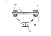
- FIG. 1 shows the configuration of the power generation element 100 according to the first embodiment.
- a power generation coil 2 made of a conductive wire is wound around the magnetic body 1, and a soft magnetic material 3 made of a soft magnetic material is in contact with the periphery of the magnetic body 1 at both ends of the magnetic body 1. It is arranged in a state where it is sandwiched and pressed.
- the magnetic material 1 used in the first embodiment can produce a large Barkhausen effect.
- the large Barkhausen effect is a phenomenon in which when the magnetic body 1 is magnetized, the magnetic domain wall inside the magnetic body 1 moves at once, and the magnetization direction is reversed in an extremely short time.
- a bicaloy alloy FeCoV alloy
- FeCoV alloy FeCoV alloy
- the power generation coil 2 uses a conductive wire and is arranged so as to wind and surround the magnetic body 1.
- the magnetic flux inside the magnetic body 1 changes due to the large Barkhausen effect of the magnetic body 1
- the magnetic flux passing through the power generation coil 2 changes. Therefore, an electromotive force due to electromagnetic induction is generated in the power generation coil 2, and the power generation element 100 can function.
- the power generation coil 2 using the conductive wire a copper wire having an insulating coating can be used, and the wire is formed by winding the wire around the bobbin.
- the wire diameter of the power generation coil 2 was set to 0.02 mm to 0.05 mm.
- a magnetic field generation source 12 is arranged around the magnetic body 1. Two magnetic poles, an N pole and an S pole, are used as the magnetic field generation source 12 to generate the magnetic field 11. It is also possible to generate a magnetic field 11 by using one or more sets of two magnetic poles, an N pole and an S pole, as the magnetic field generation source 12. The magnetic field 11 is applied to the magnetic body 1.
- Soft magnetic materials 3 are arranged at both ends of the magnetic material 1.
- the soft magnetic material 3 easily undergoes magnetic pole reversal and the like, and exhibits a higher magnetic permeability and a saturated magnetic flux density than the magnetic material 1 used in the first embodiment.
- FIG. 2 shows a cross-sectional view of a portion of the magnetic body 1 to which the soft magnetic body 3 is attached, cut in a direction orthogonal to the magnetic body 1.
- the block-shaped soft magnetic material 3 is formed with a groove 15 having a V-shaped cross section.
- the magnetic body 1 is arranged at a position determined by fitting with the V-shaped groove 15, and is pressed by two soft magnetic bodies 3 from above and below, that is, a V-shape formed on the soft magnetic body 3.
- the wall surface of the groove 15 is held in a state where the magnetic body 1 is pressed.
- the groove 15 formed in the block-shaped soft magnetic body 3 is formed deeper than the radius of the magnetic body 1.
- the groove 15 is formed and used at a maximum of 0.2 mm deeper than the depth of the radius of the magnetic body 1.
- the soft magnetic body 3 is formed with a groove shape having an inner diameter smaller than the outer diameter of the magnetic body 1 so that the wall surface of the groove 15 presses the magnetic body 1.
- the two block-shaped soft magnetic bodies 3 face each other, and the surfaces of the opposing soft magnetic bodies 3 other than the portion where the groove 15 is formed are in contact with each other.
- FIG. 3 to 5 show schematic cross-sectional views of the power generation element 100 cut in the longitudinal direction of each magnetic body 1, and how the magnetic field generated from each magnetic field generation source 12 is inside the magnetic body 1. It shows whether it is distributed in.
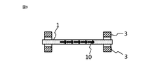
- FIG. 3 is a schematic cross-sectional view of the power generation element 100 in which the soft magnetic material 3 is pressed against both ends of the magnetic body 1 and arranged in contact with each other.
- FIG. 5 shows the soft magnetic material 3 at both ends of the magnetic body 1.
- a schematic cross-sectional view of the power generation element 100 in the case where the power generation element 100 is not used is shown.
- FIG. 4 shows an intermediate configuration between these, and although the soft magnetic material 3 is provided at both ends of the magnetic body 1, the magnetic body 1 is not pressed by the soft magnetic material 3 and the gap 18 is formed. It shows the state of having. In addition, in FIGS. 3 to 5, the power generation coil 2 is omitted.
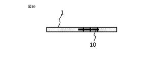
- FIG. 6 shows the distribution of the internal magnetic flux density of the magnetic body 1 of the power generation element 100 shown in FIGS. 3 to 5, and FIG. 7 shows the electromotive force of each. Further, in FIGS. 8 to 10, an arrow 10 indicates a region having a high magnetic flux density inside each magnetic material 1.
- FIG. 6 shows a comparison of the distributions of magnetic flux densities of the magnetic materials 1 of the three types of power generation elements 100 shown in FIGS. 3 to 5.
- the magnetic flux density 8A inside the magnetic body 1 placed by pressing the soft magnetic body 3 and the magnetic flux density 8B when the magnetic body 1 is placed with a gap without being pressed by the soft magnetic body 3 are shown.
- FIG. 6 in order to make it easier to understand the positional relationship between the magnetic material 1 and the distribution of the magnetic flux density, the cross-sectional views of the magnetic material 1 and the soft magnetic material 3 are made to correspond to the data of the magnetic flux density at the upper part of the drawing. Shown.
- the magnetic flux density 8C When the soft magnetic material 3 was not used, the magnetic flux density was high in the central portion of the magnetic body 1 as shown by the magnetic flux density 8C, but when it was out of the central portion, the magnetic flux density decreased sharply toward both ends. Further, in the case where the soft magnetic material 3 does not press the magnetic material 1 and has a gap between them, the soft magnetic material 3 is not used in the range where the magnetic flux density is high, as shown in the magnetic flux density 8B. Although it was wider than the magnetic flux density of 8C in the configuration, it dropped sharply at both ends of the magnetic body 1. It can be seen that the magnetic flux density 8A having the structure in which the magnetic body 1 is pressed against the soft magnetic body 3 has a wider region where the magnetic flux density is higher than the magnetic flux densities 8B and 8C having different arrangements of the soft magnetic body 3.
- FIG. 7 shows the electromotive force when the distribution of the magnetic flux density of the magnetic material 1 corresponds to the magnetic flux densities 8A to 8C shown in FIG.
- the magnetic flux density 8A corresponds to an electromotive force 9A
- the magnetic flux density 8B corresponds to an electromotive force 9B
- the magnetic flux density 8C corresponds to an electromotive force 9C. It can be confirmed that the region having a high magnetic flux density produces the largest electromotive force 9A at the widest magnetic flux density 8A.
- FIG. 8 to 10 schematically show a portion where the magnetic flux density inside the magnetic body 1 is high and the magnetization direction is reversed due to the large Barkhausen effect for three configurations in which the soft magnetic material 3 is arranged differently. It is shown by.
- FIG. 8 shows a configuration in which the soft magnetic material 3 is pressed and arranged, which is shown in a schematic cross-sectional view in FIG. It is shown that the reversal of the magnetization direction due to the Barkhaus effect occurs stably in the entire magnetic material 1. Therefore, in the power generation element having this configuration, the electromotive force of the power generation coil 2 due to electromagnetic induction is also stable and large.
- FIG. 9 shows a configuration in which the magnetic material 1 and the soft magnetic material 3 shown in FIG. 4 have voids
- FIG. 10 shows a configuration in which the soft magnetic material 3 shown in FIG. 5 is not used.
- the arrows 10 are distributed only in a part of the magnetic material 1, and the large Barkhausen effect occurs only in a part of the magnetic material 1. Therefore, it can be seen that the reversal of the magnetization direction becomes unstable and sufficient power generation characteristics cannot be obtained as the power generation element 100.
- the power generation element 100 of the first embodiment will be described together with configurations and materials that can be used in addition to the configurations and materials described so far.
- a permalloy alloy NiFe alloy
- an amorphous alloy or the like can be used in addition to the bicaloy alloy.
- surface treatment such as bending, heat treatment and plating, and chemical treatment can be used.
- the coercive force can also be controlled by adding additives to these alloy materials.
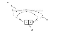
- the shape of the magnetic body 1 is a wire shape in the first embodiment, but as shown in FIG. 11, even a sheet-shaped magnetic body 22 can be used by winding the power generation coil 2.
- a wire diameter of 0.1 mm to 1 mm was used for the magnetic material 1, but the present invention is not limited to this, and a wire diameter of less than 0.1 mm and a wire diameter thicker than 1 mm can be used.
- the magnetic material 1 having a circular cross-sectional shape is used, but the present invention is not limited to this, and it can also be used as a polygon such as a quadrangle or a thin flat plate. ..
- the coercive force of the outer peripheral portion of the magnetic body 1 is smaller than that of the central portion, the coercive force of the outer peripheral portion and the central portion may be different, and the coercive force of the outer peripheral portion is larger. Can be used in the same manner.
- the material used for the soft magnetic material 3 a cold-rolled steel sheet is suitable because it can be processed into a desired shape with high accuracy and is inexpensive.
- the soft magnetic material 3 having a higher magnetic permeability and saturation magnetic flux density than the magnetic material 1 may be used, and soft ferrite, permalloy, permendur, silicon steel, amorphous magnetic alloy, nanocrystal magnetic alloy, and sendust may also be used. Can be done.
- the soft magnetic material can be processed into particles and contained in a plastic material or the like for use.
- the soft magnetic material 3 using this plastic material has a feature that it can be easily formed into various shapes by injection molding or the like.
- a block-shaped soft magnetic body 3 having a V-shaped groove 15 formed therein is used vertically, but the cross-sectional shape of the groove 15 is fitted with the magnetic body 1.
- the magnetic body 1 can be arranged at a predetermined position, a quadrangle, a semicircular shape, and a semi-elliptical shape can be used in addition to the V-shape.
- the groove 15 is not always necessary, and even if the soft magnetic material 3 does not form the groove 15, as shown in FIG.
- the magnetic material 1 And the position of the soft magnetic body 3 is arranged at a predetermined position by the jig P, and the adhesive 16 is applied and cured to form the magnetic body 1 into two soft magnetic bodies as shown in FIG. 12 (b). It can be stably held on the flat surface of the body 3.
- the type of adhesive that adheres the two soft magnetic materials 3 arranged one above the other to each other is not particularly limited, but the anaerobic curing type or the anaerobic curing type is used because the adhesive is easy to handle and the curing time is short.
- a curable adhesive that is a combination of an anaerobic curable type and other curable types is suitable.
- a heat-curing type, a curing agent mixed type, an ultraviolet curing type, a heat-melting type, or an adhesive in which these curing methods are combined can also be used.
- the two soft magnetic bodies 3 can be pressed and held against each other.
- the soft magnetic material 3 can be joined by caulking.
- adhesive tape, press fitting, rivet joining, pressure welding, welding, brazing, snap fit and the like can be used.
- the power generating coil 2 uses a conductive wire of a copper wire having an insulating coating, but it is sufficient if the same conductivity can be ensured, and an aluminum wire, gold, silver, or a copper alloy is used. , Aluminum alloys can also be used. Further, for the power generation coil 2, a wire having a wire diameter of 0.02 mm to 0.05 mm was used as the conductive wire, but the present invention is not limited to this, and the diameter of the magnetic body 1 to be wound and the power generation element are not limited to this. The wire diameter of the conductive wire constituting the power generation coil 2 can be selected based on the size of 100 or the like.
- a conductive wire was wound around a bobbin to form the power generation coil 2, but the present invention is not limited to this. It is also possible to wind a conductive wire around the jig and tool, fix it with an adhesive and a self-bonding wire, remove it from the jig and tool, and use it as a power generation coil 2.
- the power generation coil 2 is preferably arranged so as to surround the magnetic body 1 so that the change in magnetic flux due to the large Barkhausen effect of the magnetic body 1 is maximized.
- the magnetic field 17 generated by the magnetic body 1 does not surround the magnetic body 1 so as to pass through the power generation coil 2 along the magnetic body 1. It may be arranged.
- a permanent magnet As the magnetic field generation source 12. However, it suffices to stably generate the magnetic field 11, and even an electromagnet can be used.
- the permanent magnet rare earth magnets such as ferrite magnets, neodymium magnets, alnico magnets, and samarium-cobalt magnets can be used. Further, it is also possible to contain magnetic material particles in a plastic material and mold it by injection molding or the like to use it as a magnet.
- FIG. 1 As a configuration of the power generation element, as shown in FIG. 1, a case where a power generation element 100 composed of a magnetic material 1, a power generation coil 2 and a soft magnetic material 3 is paired with one magnetic field generation source 12 is shown. However, as shown in FIG. 14, three sets of power generation elements 100a, 100b, and 100c may be arranged with respect to one magnetic field generation source 12A.
- the magnetic field generation source 12A has a disk shape, and power generation elements 100a to 100c are arranged above the magnetic field generation source 12A at intervals from the magnetic field generation source 12A.
- the magnetic field generation source 12A rotates about the point O. Note that FIG. 14 is an example of the arrangement method, and the present invention is not limited to this.
- the electromotive force generated in the power generation element 100 can be used as a power source for driving the IC.
- a magnetic sensor that notifies the generation of the magnetic field 11 by a pulse voltage by utilizing the fact that the fluctuation of the magnetic field 11 caused by the large bulkhausen effect is steep and the electric power generated from the power generation coil 2 by electromagnetic induction becomes a pulse shape. Can be used.
- the IC 23 uses the characteristics of stable power supply and pulse of the power generation element 100, as shown in FIG. 15, the IC 23 operates by combining the power generation element 100 with the IC 23 and the like and using the power generated in a pulse shape by the power generation element 100 as a power source.
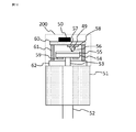
- a non-powered magnetic sensor 50 for detecting the generation of a pulse of the power generation element 100 with the IC 23, and a reflective optical encoder 200 whose cross-sectional schematic diagram is shown in FIG. 16 can also be obtained.
- FIG. 16 is a schematic view showing a cross-sectional configuration of the reflective optical encoder 200.
- the reflective optical encoder 200 is attached to the motor 51.
- a rotary shaft 53 is coaxially connected to the motor rotary shaft 52 of the motor 51, and a hub member 54 to which a disk-shaped scale plate 55 is attached is fixed to the rotary shaft 53.
- the substrate 60, the housing 61 arranged around it, and the housing 62 through which the rotating shaft 53 penetrates cover the periphery of the scale plate 55, and the non-powered magnetic sensor 50 is applied to the outer surface of the substrate 60, and the irradiation light indicated by the arrow 49 is applied to the inner surface.
- a light emitting unit 57 that emits light and a light receiving unit 58 that receives the reflected light indicated by the arrow 56 are arranged.
- Magnetism is applied to the hub member 54.
- a magnet 59 is fixed to the back surface of the hub member 54 in order to impart magnetism to the hub member 54. Further, the magnet 59 can be arranged between the disk-shaped scale plate 55 and the hub member 54. In this case, the step of fixing the hub member 54 and the magnet 59 can be omitted, and the production efficiency can be improved. Further, by molding the magnet 59 into the shape of the hub member 54, since the magnet 59 has the function of the hub member 54, the number of constituent parts can be reduced and the production efficiency can be improved.
- the material of the hub member 54 can be formed by dispersing magnetic particles in a plastic material or the like, and the hub member 54 can be easily formed into various shapes by injection molding.
- the hub member 54 is not limited to the configuration in which magnetic particles are dispersed in a plastic material or the like, and may be formed of ferrite, alnico (Al—Ni—Co), or a rare earth element.
- the reflective optical encoder 200 when the rotating shaft 53 is rotated, the irradiation light emitted from the light projecting portion 57 is transmitted by a high-reflecting portion having a high light reflectance and a low-reflecting portion having a low light reflectance formed on the scale plate 55.
- the rotation angle and the rotation speed are detected by reflecting the light in the configured pattern and detecting the change in the amount of the reflected light by the light receiving unit 58.
- the power generation element 100 generates power by changing the direction of the magnetic force emitted from the hub member 54, thereby detecting the number of rotations rotated from the reference position.
- the reflective optical encoder 200 detects the rotation angle, the number of rotations, and the rotation speed of the rotating shaft 53 to determine the rotation angle and the number of rotations of the motor 51.
- the rotation speed can be detected.
- Embodiment 2 The basic structure of the power generation element 100 according to the second embodiment is the same as that of the first embodiment, and the structure in which the magnetic body 1 is pressed and arranged by the soft magnetic body 3 is different.
- FIG. 17 shows a cross-sectional view of a portion of the power generation element 100 in which the soft magnetic body 4 is attached to the magnetic body 1 cut in a direction orthogonal to the magnetic body 1.
- the two block-shaped soft magnetic materials 3 were pressed against each other and held, but the soft magnetic material shown in FIG. 17 was held.
- the magnetic material 1 is pressed by the block-shaped soft magnetic material 4 having the groove 15 formed and the block-shaped non-magnetic material 20 having the groove 15 formed in the same manner as the soft magnetic material 4, and the magnetic material 1 is softened.
- the magnetic material 4 and the non-magnetic material 20 are fixed and held by the adhesive 16.
- the shape of the groove 15 and the type of the adhesive 16 can be used as long as the soft magnetic body 4 has a shape and a material that can press and hold the magnetic body 1 as in the first embodiment. ..
- the non-magnetic material 20 and the soft magnetic material 4 press and hold the magnetic material 1 so that the magnetic material 1 and the soft magnetic material 4 can be stably brought into contact with each other due to the large Barkhausen effect generated by the magnetic material 1. It is possible to stabilize the change in the magnetization direction and obtain power generation characteristics with little fluctuation. Further, the power generation element 100 can be applied to a magnetic sensor and an encoder.
- Embodiment 3 The basic structure of the power generation element 100 according to the third embodiment is the same as that of the first embodiment, and the structure in which the magnetic body 1 is pressed and arranged by the soft magnetic body 3 is different.
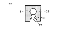
- FIG. 18 shows a cross-sectional view of a portion of the power generation element 100 in which the soft magnetic body 24 is attached to the magnetic body 1 cut in a direction orthogonal to the magnetic body 1.
- the two block-shaped soft magnetic materials 3 are pressed against each other and held, but the soft magnetic material shown in FIG. 18 is held.
- a U-shaped soft magnetic material 24 is used, and the magnetic material 1 is pressed against the fitting groove 27, which is an inner portion of the U-shape, to be fixed and held.
- the inner diameter of the inner bottom portion of the U-shape is formed to be equal to or smaller than the outer diameter of the magnetic body 1, and the distance between both ends of the tip portion of the U-shape is formed to be smaller than the diameter of the bottom portion.
- the fitting groove 27 expands, and after the fitting, the magnetic body 1 is schematically indicated by the arrow 30 by the elastic force of the soft magnetic body 24. Press as if.
- the fitting groove 27 can be used as long as it has a shape and a material that the soft magnetic material 24 can press and hold the magnetic material 1.
- the block-shaped soft magnetic material 25 can also be used by forming the fitting groove 27.
- the inner diameter of the bottom of the fitting groove 27 is formed to be smaller than the outer diameter of the magnetic body 1.
- the soft magnetic bodies 24 and 25 press and hold the magnetic body 1 as shown by the arrow 30, so that the magnetic body 1 and the soft magnetic bodies 24 and 25 can be stably brought into contact with each other. Therefore, it is possible to stabilize the change in the magnetization direction due to the large Barkhausen effect generated in the magnetic material 1 and obtain power generation characteristics with little change. Further, the power generation element 100 can be applied to a magnetic sensor and an encoder.
- Embodiment 4 The basic structure of the power generation element 100 according to the fourth embodiment is the same as that of the first embodiment, and the structure in which the magnetic body 1 is pressed and arranged by the soft magnetic body 3 is different.
- FIG. 20 shows a cross-sectional view of a portion of the power generation element 100 in which the soft magnetic body 4 is attached to the magnetic body 1 cut in a direction orthogonal to the magnetic body 1.
- the two block-shaped soft magnetic materials 3 were pressed against each other and held, but the soft magnetic material shown in FIG. 20 was held.
- the magnetic body 1 is pressed, fixed and held by the block-shaped soft magnetic material 4 having the groove 15 formed and the adhesive 21.
- the shape of the groove 15 and the type of the adhesive 21 can be used as long as the soft magnetic body 4 has a shape and a material that can press and hold the magnetic body 1 as in the first embodiment. ..
- the adhesive 21 when the adhesive 21 is cured, it shrinks and the magnetic material 1 can be pressed against the groove wall surface of the soft magnetic material 4. As shown in FIG.
- the magnetic material 1 was pressed against the soft magnetic material 4 by applying the adhesive 21 and curing the magnetic material 1 against the soft magnetic material 4 with the jig Q. It may be held in a state. Further, as shown in FIG. 22, a structure in which an fitting groove 27, which is an inner portion of the U-shape, is formed in the U-shaped soft magnetic body 26, and the fitted magnetic body 1 is held by the adhesive 21 and pressed. It may be.
- the soft magnetic bodies 4 and 26 press and hold the magnetic body 1, so that the magnetic body 1 and the soft magnetic bodies 4 and 26 can be stably brought into contact with each other, and a large bulk generated by the magnetic body 1 can be obtained. It is possible to stabilize the change in the magnetization direction due to the Barkhaus effect and obtain power generation characteristics with little fluctuation. Further, the power generation element 100 can be applied to a magnetic sensor and an encoder.
- Embodiment 5 The basic structure of the power generation element 100 according to the fifth embodiment is the same as that of the first embodiment, and the attachment structure of the soft magnetic body 3 to the magnetic body 1 is different.
- FIG. 23 shows a perspective view illustrating a portion where the soft magnetic body 5 is arranged on the magnetic body 1 of the power generation element 100.
- the soft magnetic material 5 has a cylindrical shape and is provided with an insertion hole 13 penetrating between the circular upper surface and the bottom surface.
- a magnetic body 1 that produces a large Barkhausen effect is press-fitted into the insertion hole 13, and the magnetic body 1 is pressed and fixed by the cylindrical soft magnetic body 5.
- FIG. 24 shows the cross-sectional structure of the cylindrical soft magnetic material 5 provided with the insertion hole 13 shown in FIG. 23 when it is divided from the upper surface to the bottom surface along the insertion hole 13.
- tapered portions 14 are formed on the upper surface side and the bottom surface side of the insertion hole 13 of the soft magnetic material 5 so that the opening portion increases outward from the central portion of the insertion hole 13.
- the outer diameter of the magnetic body 1 is formed larger than the inner diameter of the insertion hole 13 formed in the soft magnetic body 5.
- the fitting tolerance which is the difference between the inner diameter of the insertion hole 13 of the soft magnetic body 5 and the outer diameter of the magnetic body 1, should be +50 micron or less in terms of workability and fixing strength by pressing. Preferred from the point of view.
- the magnetic body 1 By press-fitting the magnetic body 1 into the insertion hole 13 of the soft magnetic body 5, the magnetic body 1 can be pressed and arranged by tight fitting.
- the tight fitting step not only press fitting but also shrink fitting or the like in which the insertion hole 13 is heated and expanded to fit the magnetic material 1 can be used.
- the soft magnetic body 5 and the magnetic body 1 are brought into contact with each other by pressing the magnetic body 1 from the fitting, and the magnetic resistance between the magnetic body 1 and the soft magnetic body 5 is increased. It can be made smaller. Therefore, the magnetic field 11 can be stably applied to the magnetic body 1 by the magnetic field generation source 12. As a result, the change in the magnetization direction due to the large Barkhausen effect is stable, and the electromotive force can be stably generated in the power generation coil 2 by electromagnetic induction.
- the tapered portion 14 in the insertion hole 13 of the soft magnetic material 5 as described above in order to efficiently perform the insertion work.
- the efficiency of the insertion work by press fitting can be improved, and a power generation element capable of stably generating an electromotive force can be obtained.
- the power generation element 100 can be applied to a magnetic sensor and an encoder.
- the soft magnetic material 6 used in the sixth embodiment is not only composed of a soft magnetic material made of soft ferrite, permalloy, etc., but is made of soft magnetic material particles obtained by finely processing the soft magnetic material into particles, such as an adhesive. It is characterized by being added to the plastic material of.
- FIG. 25 shows a schematic diagram of the power generation element 120 of the sixth embodiment.
- the basic configuration is the same as that of the first embodiment, in which a power generation coil 2 made of a conductive wire is arranged around the magnetic body 1, and soft magnetic materials 6 are attached to both ends of the magnetic body 1. ing.
- the soft magnetic material 6 is made by processing soft ferrite to a particle size of 5 microns or less and adding it to a plastic material.
- the plastic material to which the soft ferrite particles are added can be processed into a shape that can be attached to both ends of the magnetic body 1 by a molding apparatus. For example, by forming a cylindrical shape having an insertion hole 13 similar to the soft magnetic body 5 of FIG. 23 described in the fifth embodiment, it can be easily attached to both ends of the magnetic body 1.
- soft ferrite is used as the particulate soft magnetic material to be added to the plastic material, but the present invention is not limited to this, and any material that can be processed into particles is used in the same manner. Permalloy, silicon steel, etc. can be used.
- a heat-curing type, a curing agent mixed type, an ultraviolet curing type, an anaerobic curing type, a heat-melting type, or a composite curing type plastic material thereof is used.
- a heat-curing type, a curing agent mixed type, an ultraviolet curing type, an anaerobic curing type, a heat-melting type, or a composite curing type plastic material thereof is used.
- an ultraviolet curable type or a composite plastic material of another curable type and an ultraviolet curable type, which has a short time to cure is suitable.
- a plastic material to which a particulate soft magnetic material is added is molded to obtain a soft magnetic material 6, which is fitted to both ends of the magnetic material 1 without any gaps. Since the magnetic material 1 that produces the large bulkhausen effect is pressed and contacted by the soft magnetic material 6, the magnetic field 11 can be stably applied to the magnetic material 1, and the change in the magnetization direction due to the large bulkhausen effect is stable. By electromagnetic induction, the electromotive force can be stably generated in the power generation coil 2. Further, the power generation element 120 can be applied to a magnetic sensor and an encoder.
- Embodiment 7 In the power generation element 130 of the seventh embodiment, as shown in the schematic view of FIG. 26, the soft magnetic material 7 is used by forming a wire from a soft magnetic material such as soft ferrite or permalloy and winding it around the magnetic material 1. It is a feature. In the processing of the soft magnetic body 7, the inner diameter of the wound soft magnetic body 7 is formed to be smaller than the outer diameter of the magnetic body 1, so that when the soft magnetic body 7 is attached to the magnetic body 1, the soft magnetic body 7 presses and arranges the soft magnetic body 7. be able to.
- a soft magnetic material such as soft ferrite or permalloy
- the wound soft magnetic body 7 presses and arranges the magnetic body 1 that produces a large Barkhausen effect
- the magnetic resistance between the soft magnetic body 7 and the magnetic body 1 can be kept small, and a magnetic field is generated.
- the magnetic field 11 of the source 12 can be stably applied to the magnetic material 1. Therefore, the change in the magnetization direction due to the large Barkhausen effect is stabilized, and a stable electromotive force can be generated in the power generation coil 2 by electromagnetic induction.
- the power generation element 100 can be applied to a magnetic sensor and an encoder.
- the block-shaped soft magnetic material 3 when heat is applied to the power generation elements 100, 110, 120 from the outside and the magnetic material 1 becomes hot, the block-shaped soft magnetic material 3, etc.
- the thermal expansion coefficient of the magnetic body 1 is significantly different from that of the magnetic body 1, a large stress is applied to the magnetic body 1 at a high temperature, and the magnetic characteristics of the magnetic body 1 change. As a result, the change in the magnetization direction due to the large Barkhausen effect may be small.
- the soft magnetic material 7 When the soft magnetic material 7 is wound and used as in the seventh embodiment, even if there is a difference in the coefficient of thermal expansion between the soft magnetic material 7 and the magnetic material 1, even at a high temperature, the magnetic material 1 is transferred to the magnetic material 1. The stress can be reduced. Therefore, since the soft magnetic body 7 can be pressed and held by the magnetic body 1, the magnetic resistance can be reduced and the stable magnetic field 11 can be passed through the magnetic body 1, and the power generation coil 2 can be used. A stable electromotive force can be generated. Further, the power generation element 130 can be applied to a magnetic sensor and an encoder.
Abstract
大バルクハウゼン効果を生じる磁性体と、磁性体に巻回して配置された発電用コイルと、磁性体の両端部に、磁性体に接するとともに、磁性体を押圧するように形成された軟磁性体と、を備えたことにより、磁性体の磁束密度の均一性を高め、大バルクハウゼン効果を安定して生じさせることにより、安定性の高い発電素子を得る。
Description
本願は、発電素子、これを用いた磁気センサ、エンコーダおよびモータに関するものである。
大バルクハウゼン効果は、外部磁界の変化に応じて磁化方向を急反転させる現象である。
この大バルクハウゼン効果が生じる磁性体の周囲に導電性ワイヤからなる発電用コイルを設け、外部磁界を印加して大バルクハウゼン効果により磁化方向を反転させると、電磁誘導により発電用コイルに起電力を生じる発電素子を得ることができる。
この大バルクハウゼン効果が生じる磁性体の周囲に導電性ワイヤからなる発電用コイルを設け、外部磁界を印加して大バルクハウゼン効果により磁化方向を反転させると、電磁誘導により発電用コイルに起電力を生じる発電素子を得ることができる。
この発電素子を構成する磁性体の両端部に軟磁性体を配置することによって磁性体の末端で生じる反磁界が軽減され、磁性体に生じる磁束の均一性を高めることができる。その結果、外部から印加する磁界の強度及び極性に依存することなく安定して大バルクハウゼン効果を生じさせることができ、変動の少ない発電特性を得ることができる(例えば、特許文献1)。
特許文献1には、磁性体の両端部に軟磁性体を備えることで、磁性体の末端に生じる反磁界の影響を低減し、安定した発電特性を得ることができると記載されている。
しかし、磁性体に軟磁性体を取り付ける場合、一般に軟磁性体に貫通穴を形成し、磁性体を挿入することで行うが、穴の内径及び磁性体の外径にばらつきが生じると、軟磁性体と磁性体との間の空隙による磁気抵抗が変動し、磁性体に生じる磁束が不安定となり、発電特性の安定性も低下するという問題があった。
しかし、磁性体に軟磁性体を取り付ける場合、一般に軟磁性体に貫通穴を形成し、磁性体を挿入することで行うが、穴の内径及び磁性体の外径にばらつきが生じると、軟磁性体と磁性体との間の空隙による磁気抵抗が変動し、磁性体に生じる磁束が不安定となり、発電特性の安定性も低下するという問題があった。
本願は上記のような課題を解決するためになされたものであって、磁性体の大バルクハウゼン効果が安定して生じ、安定性の高い発電特性を有する発電素子を得ることを目的とする。
本願の発電素子は、大バルクハウゼン効果を生じる磁性体と、磁性体に巻回して配置された発電用コイルと、磁性体の両端部に、磁性体に接するとともに、磁性体を押圧するように形成された軟磁性体と、を備える。
本願の発電素子によれば、磁性体の大バルクハウゼン効果が安定して生じ、安定性の高い発電素子を得ることができる。
実施の形態の説明及び各図において、同一の符号を付した部分は、同一又は相当する部分を示すものである。
実施の形態1.
実施の形態1に係る発電素子を図1~図16を用いて説明する。
<発電素子の構成>
図1は、本実施の形態1に係る発電素子100の構成を示している。
磁性体1の周囲に導電性ワイヤからなる発電用コイル2が巻回され、磁性体1の両端部には軟磁性材料からなる軟磁性体3が、磁性体1の周囲に接し、磁性体1を挟み押圧した状態で配置されている。
磁性体1の近傍には、磁性体1に磁界を印加する、例えば磁石である磁界発生源12が配置され、周囲に磁界11が発生している。
実施の形態1に係る発電素子を図1~図16を用いて説明する。
<発電素子の構成>
図1は、本実施の形態1に係る発電素子100の構成を示している。
磁性体1の周囲に導電性ワイヤからなる発電用コイル2が巻回され、磁性体1の両端部には軟磁性材料からなる軟磁性体3が、磁性体1の周囲に接し、磁性体1を挟み押圧した状態で配置されている。
磁性体1の近傍には、磁性体1に磁界を印加する、例えば磁石である磁界発生源12が配置され、周囲に磁界11が発生している。
本実施の形態1で用いた磁性体1は、大バルクハウゼン効果を生じることができる。大バルクハウゼン効果は、磁性体1が磁化する際に、磁性体1の内部の磁壁が一度に移動し、極めて短時間に磁化方向が反転する現象である。
大バルクハウゼン効果を生じさせる磁性体1としては、バイカロイ合金(FeCoV合金)を用いることができる。大バルクハウゼン効果を生じさせるためには、内部応力分布、組成分布を制御して外周部と中心部とで保磁力が異なる構成とすることが必要である。
そこで、バイカロイ合金を0.1mm~1mmのワイヤ状に伸線加工した後、ひねり加工を施して外周部と中心部とで保磁力が異なる構成の磁性体1を得る。
そこで、バイカロイ合金を0.1mm~1mmのワイヤ状に伸線加工した後、ひねり加工を施して外周部と中心部とで保磁力が異なる構成の磁性体1を得る。
発電用コイル2は導電性ワイヤを用い、磁性体1を巻回して囲むように配置されている。
磁性体1の大バルクハウゼン効果により、磁性体1の内部の磁束が変化すると、発電用コイル2を通る磁束が変化する。そのため、発電用コイル2に電磁誘導による起電力が発生し、発電素子100として機能することができる。
磁性体1の大バルクハウゼン効果により、磁性体1の内部の磁束が変化すると、発電用コイル2を通る磁束が変化する。そのため、発電用コイル2に電磁誘導による起電力が発生し、発電素子100として機能することができる。
導電性ワイヤを用いた発電用コイル2は、絶縁被覆が施された銅線を用いることができ、線材をボビンに巻線して形成する。
発電用コイル2の線径は0.02mm~0.05mmとして用いた。
発電用コイル2の線径は0.02mm~0.05mmとして用いた。
磁性体1の周囲部分には、磁界発生源12を配置する。
N極とS極の2つの磁極を磁界発生源12として用い、磁界11を生じさせる。N極とS極の2つの磁極を磁界発生源12として一組以上用い、磁界11を発生させることもできる。磁界11は、磁性体1に印加される。
N極とS極の2つの磁極を磁界発生源12として用い、磁界11を生じさせる。N極とS極の2つの磁極を磁界発生源12として一組以上用い、磁界11を発生させることもできる。磁界11は、磁性体1に印加される。
磁性体1の両端部には各々軟磁性体3が配置されている。
軟磁性体3とは、磁極の反転等が容易に生じ、本実施の形態1で用いる磁性体1と比較して、高い透磁率及び飽和磁束密度を示す。
軟磁性体3とは、磁極の反転等が容易に生じ、本実施の形態1で用いる磁性体1と比較して、高い透磁率及び飽和磁束密度を示す。
図2には、磁性体1に軟磁性体3を取り付けた部分について、磁性体1に直交する方向で切断した断面図を示している。
図1の模式図と図2の断面図に示したように、ブロック形状の軟磁性体3には断面形状がV字形の溝15が形成されている。磁性体1は、このV字形の溝15と嵌合して決められた位置に配置され、上下から2つの軟磁性体3に押圧された状態、すなわち、軟磁性体3に形成されたV字形の溝15の壁面が磁性体1を押圧した状態で保持されている。
図1の模式図と図2の断面図に示したように、ブロック形状の軟磁性体3には断面形状がV字形の溝15が形成されている。磁性体1は、このV字形の溝15と嵌合して決められた位置に配置され、上下から2つの軟磁性体3に押圧された状態、すなわち、軟磁性体3に形成されたV字形の溝15の壁面が磁性体1を押圧した状態で保持されている。
ブロック形状の軟磁性体3に形成された溝15は、磁性体1の半径より深く形成されている。本実施の形態1では、磁性体1の半径の深さよりも最大で0.2mm深く溝15が形成され用いられている。溝15の壁面が、磁性体1を押圧するように、磁性体1の外径よりも小さい内径の溝形状を軟磁性体3に形成する。
2つのブロック形状の軟磁性体3を対向させ、溝15が形成された部分以外の対向する軟磁性体3の面は、接触している。この接触する面に接着剤16を塗布して硬化することにより、磁性体1を押圧した状態を維持する。
2つのブロック形状の軟磁性体3を対向させ、溝15が形成された部分以外の対向する軟磁性体3の面は、接触している。この接触する面に接着剤16を塗布して硬化することにより、磁性体1を押圧した状態を維持する。
<軟磁性体による効果>
図3~図5は、発電素子100について、各々の磁性体1の長手方向に切断した断面模式図を示しており、各々の磁界発生源12から生じる磁界が、磁性体1の内部にどのように分布しているかを示している。図3は、磁性体1の両端部に軟磁性体3が押圧され、接して配置された発電素子100の断面模式図であり、図5は磁性体1の両端部に軟磁性体3を有しない場合の発電素子100の断面模式図を示している。
図3~図5は、発電素子100について、各々の磁性体1の長手方向に切断した断面模式図を示しており、各々の磁界発生源12から生じる磁界が、磁性体1の内部にどのように分布しているかを示している。図3は、磁性体1の両端部に軟磁性体3が押圧され、接して配置された発電素子100の断面模式図であり、図5は磁性体1の両端部に軟磁性体3を有しない場合の発電素子100の断面模式図を示している。
また、図4は、これらの中間の構成であり、磁性体1の両端部に軟磁性体3を備えてはいるものの、磁性体1が軟磁性体3に押圧されることなく、空隙18を有する状態を示している。なお、図3~図5において、発電用コイル2は省略している。
図6は、図3~図5に示した発電素子100の磁性体1について内部の磁束密度の分布を示しており、図7に各々の起電力を示している。また、図8~図10では、各々の磁性体1の内部の磁束密度の高い領域を矢印10で示している。
磁性体1の両端部に配置した軟磁性体3の間の磁束密度が等しい状態を均一、磁束密度が等しくない状態を不均一と評価する時、磁性体1の両端部に軟磁性体3が押圧して配置された発電素子100を示した図3では、磁性体1のほぼ全体が均一であると言える。磁性体1に軟磁性体3を押圧せず、空隙を有して配置された発電素子100を示した図4では、均一な磁界が形成される範囲が狭くなっていることがわかる。さらに、図5に示した軟磁性体3を用いない発電素子100では、磁性体1の内部の磁界の均一性は大きく低下していることがわかる。
磁性体1の両端部に配置した軟磁性体3の間の磁束密度が等しい状態を均一、磁束密度が等しくない状態を不均一と評価する時、磁性体1の両端部に軟磁性体3が押圧して配置された発電素子100を示した図3では、磁性体1のほぼ全体が均一であると言える。磁性体1に軟磁性体3を押圧せず、空隙を有して配置された発電素子100を示した図4では、均一な磁界が形成される範囲が狭くなっていることがわかる。さらに、図5に示した軟磁性体3を用いない発電素子100では、磁性体1の内部の磁界の均一性は大きく低下していることがわかる。
図6は、図3~図5に示した3種類の発電素子100の磁性体1について、磁束密度の分布を比較して示している。図6において、軟磁性体3が押圧して配置された磁性体1の内部の磁束密度8A、磁性体1が軟磁性体3に押圧されず空隙を有して配置された時の磁束密度8B、及び軟磁性体3を用いない時の磁束密度8Cを各々示している。
また、図6において、磁性体1と磁束密度の分布との位置関係を理解し易くするため、図の上部に、磁性体1及び軟磁性体3の断面図を磁束密度のデータと対応させて示している。
軟磁性体3を用いない時、磁束密度8Cで示すように磁性体1の中央部では磁束密度が高くなるものの、中央部を外れると両端部にかけて磁束密度は急激に低下した。また、軟磁性体3が磁性体1を押圧することなく、相互の間に空隙を有する構成の場合、磁束密度8Bに示すように、磁束密度が高くなる範囲は、軟磁性体3を用いない構成の磁束密度8Cより広くなるものの、磁性体1の両端部では急激に低下した。
磁性体1が軟磁性体3に押圧された構成の磁束密度8Aは、軟磁性体3の配置態様の異なる構成の磁束密度8B、8Cより磁束密度が高い領域が広くなっていることがわかる。
磁性体1が軟磁性体3に押圧された構成の磁束密度8Aは、軟磁性体3の配置態様の異なる構成の磁束密度8B、8Cより磁束密度が高い領域が広くなっていることがわかる。
磁性体1の磁束密度の分布が、図6に示した磁束密度8A~8Cに対応する時の起電力を、図7に示した。磁束密度8Aでは起電力9A、磁束密度8Bでは起電力9B、磁束密度8Cでは起電力9Cに対応している。
磁束密度の高い領域が最も広い磁束密度8Aで最も大きな起電力9Aを生じていることを確認することができる。
磁束密度の高い領域が最も広い磁束密度8Aで最も大きな起電力9Aを生じていることを確認することができる。
図8~図10は、軟磁性体3の配置態様が異なる3つの構成について、磁性体1の内部の磁束密度が高く、大バルクハウゼン効果により磁化方向の反転が生じる部分を模式的に矢印10で示している。
図8は、図3に断面模式図を示した、軟磁性体3で押圧して配置された構成であり、磁性体1のほぼ全体に渡る広い範囲に矢印10が記載されており、大バルクハウゼン効果による磁化方向の反転が、磁性体1の全体で安定して生じることを示している。そのため、この構成の発電素子では電磁誘導による発電用コイル2の起電力も安定し大きくなる。
図8は、図3に断面模式図を示した、軟磁性体3で押圧して配置された構成であり、磁性体1のほぼ全体に渡る広い範囲に矢印10が記載されており、大バルクハウゼン効果による磁化方向の反転が、磁性体1の全体で安定して生じることを示している。そのため、この構成の発電素子では電磁誘導による発電用コイル2の起電力も安定し大きくなる。
図9は、図4に示した磁性体1と軟磁性体3とが空隙を有する構成、図10は、図5に示した軟磁性体3を用いない構成を示している。図9及び図10では、図8と比較し、磁性体1の一部にのみ矢印10が分布しており、大バルクハウゼン効果は磁性体1の一部でのみ生じる。従って、磁化方向の反転は不安定となり、発電素子100として十分な発電特性を得ることはできないことがわかる。
<発電素子のその他の構成及び材料について>
本実施の形態1の発電素子100について、ここまでに説明した構成及び材料以外に用いることができる構成及び材料をまとめて説明する。
本実施の形態1の磁性体1には、バイカロイ合金の他に、パーマロイ合金(NiFe合金)、アモルファス合金等を用いることができる。また、保磁力を制御するために、伸線加工、ひねり加工の他に、曲げ加工、熱処理及びメッキ処理、化学処理などの表面処理を用いることができる。
本実施の形態1の発電素子100について、ここまでに説明した構成及び材料以外に用いることができる構成及び材料をまとめて説明する。
本実施の形態1の磁性体1には、バイカロイ合金の他に、パーマロイ合金(NiFe合金)、アモルファス合金等を用いることができる。また、保磁力を制御するために、伸線加工、ひねり加工の他に、曲げ加工、熱処理及びメッキ処理、化学処理などの表面処理を用いることができる。
これらの合金材料に添加物を加えることでも保磁力を制御することもできる。
磁性体1の形状は、本実施の形態1ではワイヤ状としたが、図11に示すように、シート状の磁性体22であっても発電用コイル2を巻回して用いることができる。
磁性体1の形状は、本実施の形態1ではワイヤ状としたが、図11に示すように、シート状の磁性体22であっても発電用コイル2を巻回して用いることができる。
磁性体1には0.1mm~1mmの線径を用いたが、これに限定されるものではなく、0.1mm未満の線径及び1mmより太い線径であっても用いることができる。また、本実施の形態1においては、断面形状が円形の磁性体1を用いたが、これに限定するものではなく、断面形状が四角形等の多角形、薄い平板状等としても用いることができる。
さらに、磁性体1の外周部の保磁力が中心部より小さい構成で用いたが、外周部と中心部の保磁力が異なっていればよく、外周部の保磁力の方が大きい構成であっても同様に用いることができる。
軟磁性体3に用いる材料は、目的とする形状に精度よく加工することができ、かつ安価であることから、冷間圧延鋼板が適している。その他に、磁性体1よりも透磁率及び飽和磁束密度が高い軟磁性体3であればよく、ソフトフェライト、パーマロイ、パーメンジュール、ケイ素鋼、アモルファス磁性合金、ナノクリスタル磁性合金、センダストも用いることができる。
また、軟磁性材料を粒子状に加工し、プラスチック材料などに含有させて用いることもできる。このプラスチック材料を用いた軟磁性体3では射出成型等により種々の形状に容易に形成することができる特徴を有する。
本実施の形態1においては、断面形状がV字形の溝15を形成したブロック形状の軟磁性体3を上下に配置した構成を用いたが、溝15の断面形状は、磁性体1と嵌合して磁性体1を決められた位置に配置することができればよく、V字形以外に、四角形、半円形、半楕円形も用いることができる。なお、例えば、磁性体1が板状の場合であれば、必ずしも溝15は必要なく、溝15を形成しない軟磁性体3であっても、図12(a)で示すように、磁性体1と軟磁性体3の位置を治具Pにより、決められた位置に配置し、接着剤16を塗布して硬化させることで、図12(b)で示すように磁性体1を2つの軟磁性体3の平坦な面で安定して保持することができる。
上下に配置された2つの軟磁性体3の相互間を接着する接着剤の種類は特に限定するものではないが、接着剤の取り扱いの容易さ、硬化時間が短い点から、嫌気硬化型、または嫌気硬化型とその他の硬化型が複合した硬化型の接着剤が適している。その他に、加熱硬化型、硬化剤混合型、紫外線硬化型、熱溶融型、またはこれらの硬化方法が複合した接着剤も用いることができる。
また、上下に配置した軟磁性体3を外部から固定する治具を用いることで、2つの軟磁性体3を相互に押圧し保持することができる。相互に押圧し、保持する手法としては、軟磁性体3をカシメ加工に接合させることもできる。その他に、粘着テープ、圧入、リベット接合、圧接、溶接、ろう接、スナップフィット等を用いることができる。
本実施の形態1において発電用コイル2は、絶縁被膜が施された銅線の導電性ワイヤを用いたが、同様の導電性を確保することができればよく、アルミニウム線、金、銀、銅合金、アルミニウム合金も用いることができる。
また、発電用コイル2には、線径が0.02mm~0.05mmの線材を導電性ワイヤとして用いたが、これに限定されるものではなく、巻回する磁性体1の直径、発電素子100の大きさ等に基づいて発電用コイル2を構成する導電性ワイヤの線径を選ぶことができる。
また、発電用コイル2には、線径が0.02mm~0.05mmの線材を導電性ワイヤとして用いたが、これに限定されるものではなく、巻回する磁性体1の直径、発電素子100の大きさ等に基づいて発電用コイル2を構成する導電性ワイヤの線径を選ぶことができる。
発電用コイル2の形成には、導電性ワイヤをボビンに巻回して用いたが、これに限定されるものではない。治工具に導電性ワイヤを巻回し、接着剤及び自己融着線を用いて固定して、治工具から取り外して発電用コイル2として用いることもできる。
発電用コイル2の配置場所は、図1に示すように、磁性体1の大バルクハウゼン効果による磁束の変化が最も大きくなるよう、磁性体1を囲んで配置することが好ましい。ただし、図13の発電素子110の構成図に示すように、磁性体1を囲むのではなく、磁性体1によって発生する磁界17が、発電用コイル2を通るように、磁性体1に沿って配置してもよい。
磁界発生源12としては、永久磁石を用いることが好ましい。ただし、安定して磁界11を発生すればよく、電磁石であっても用いることができる。
永久磁石としては、フェライト磁石、ネオジム磁石、アルニコ磁石、サマリウムコバルト磁石など希土類磁石を用いることできる。また、プラスチック材料に磁性材料粒子を含有させ、射出成型等により成形して磁石として用いることもできる。
永久磁石としては、フェライト磁石、ネオジム磁石、アルニコ磁石、サマリウムコバルト磁石など希土類磁石を用いることできる。また、プラスチック材料に磁性材料粒子を含有させ、射出成型等により成形して磁石として用いることもできる。
発電素子の構成としては、図1に示すように、1つの磁界発生源12に対して、磁性体1と発電用コイル2と軟磁性体3からなる発電素子100が1組の場合を示したが、図14に示すように、1つの磁界発生源12Aに対し、3組の発電素子100a、100b、100cが配置されていてもよい。磁界発生源12Aは、円盤形状であり、その上部に、磁界発生源12Aと間隔をおいて、発電素子100a~100cが配置されている。磁界発生源12Aは、点Oを中心に回転する。なお、図14は、配置の仕方の一例であり、これに限るものではない。
<発電素子の特性>
本実施の形態1で示した発電素子100、110では、軟磁性体3が、大バルクハウゼン効果を生じる磁性体1を押圧し接触して配置されているため、磁性体1と軟磁性体3の間の磁気抵抗は小さくすることができる。そのため、磁界発生源12によって印加される磁界11を安定して磁性体1に与えることができ、大バルクハウゼン効果による磁化方向の反転を安定化し、電磁誘導によって、発電用コイル2から安定して起電力を発生させることができる。
本実施の形態1で示した発電素子100、110では、軟磁性体3が、大バルクハウゼン効果を生じる磁性体1を押圧し接触して配置されているため、磁性体1と軟磁性体3の間の磁気抵抗は小さくすることができる。そのため、磁界発生源12によって印加される磁界11を安定して磁性体1に与えることができ、大バルクハウゼン効果による磁化方向の反転を安定化し、電磁誘導によって、発電用コイル2から安定して起電力を発生させることができる。
安定的に起電力を発生する発電素子100を用いることで、発電素子100に発生した起電力を、ICを駆動する電源として用いることができる。
また、大バルクハウゼン効果によって生じる磁界11の変動が急峻であり、電磁誘導によって発電用コイル2から発生する電力がパルス状となることを利用し、パルス電圧により磁界11の発生を知らせる磁気センサとして用いることができる。
さらに、発電素子100の安定した電源供給とパルスという特徴を用い、図15に示すように、発電素子100とIC23などと組み合わせ、発電素子100でパルス状に発生する電力を電源としてIC23が動作し、同時に発電素子100のパルスの発生をIC23で検出する無電源磁気センサ50として用いることができ、図16に断面模式図を示した反射型光学式エンコーダ200を得ることもできる。
また、大バルクハウゼン効果によって生じる磁界11の変動が急峻であり、電磁誘導によって発電用コイル2から発生する電力がパルス状となることを利用し、パルス電圧により磁界11の発生を知らせる磁気センサとして用いることができる。
さらに、発電素子100の安定した電源供給とパルスという特徴を用い、図15に示すように、発電素子100とIC23などと組み合わせ、発電素子100でパルス状に発生する電力を電源としてIC23が動作し、同時に発電素子100のパルスの発生をIC23で検出する無電源磁気センサ50として用いることができ、図16に断面模式図を示した反射型光学式エンコーダ200を得ることもできる。
図16は反射型光学式エンコーダ200の断面構成を示す模式図である。
反射型光学式エンコーダ200は、モータ51に取り付けられている。モータ51のモータ回転軸52と同軸に回転軸53が接続され、回転軸53には円盤型のスケール板55が取付けられたハブ部材54が固定されている。
基板60、周囲に配置したハウジング61及び回転軸53が貫通するハウジング62でスケール板55の周囲を覆い、基板60の外面には無電源磁気センサ50、内面には矢印49で示した照射光を発する投光部57と矢印56で示した反射光を受ける受光部58が配置されている。
反射型光学式エンコーダ200は、モータ51に取り付けられている。モータ51のモータ回転軸52と同軸に回転軸53が接続され、回転軸53には円盤型のスケール板55が取付けられたハブ部材54が固定されている。
基板60、周囲に配置したハウジング61及び回転軸53が貫通するハウジング62でスケール板55の周囲を覆い、基板60の外面には無電源磁気センサ50、内面には矢印49で示した照射光を発する投光部57と矢印56で示した反射光を受ける受光部58が配置されている。
ハブ部材54には磁性が付与されている。ハブ部材54に磁性を付与するためにハブ部材54の裏面に磁石59を固定する。また、磁石59を円盤型のスケール板55とハブ部材54の間に配置することもできる。この場合、ハブ部材54と磁石59を固定する工程を省略することができ、生産効率の向上を図ることができる。さらに、磁石59をハブ部材54の形に成形することで、磁石59がハブ部材54の機能を有するため、構成する部品点数を削減することができ、生産効率を向上させることができる。
ハブ部材54の材料としては、プラスチック材料などに磁性粒子を分散させて形成することができ、射出成形によりハブ部材54を容易に様々な形状にすることができる。
ハブ部材54は、プラスチック材料などに磁性粒子を分散させて形成する構成に限らず、フェライト、アルニコ(Al-Ni-Co)、または希土類で形成しても良い。
ハブ部材54は、プラスチック材料などに磁性粒子を分散させて形成する構成に限らず、フェライト、アルニコ(Al-Ni-Co)、または希土類で形成しても良い。
反射型光学式エンコーダ200では、回転軸53の回転時に、投光部57から出た照射光を、スケール板55上に形成された、光の反射率が高い高反射部と低い低反射部で構成されるパターンで反射し、反射光の光量変化を受光部58で検出することにより、回転角度及び回転速度を検出する。さらに、ハブ部材54から放出される磁力の方向変化によって発電素子100が発電することにより基準位置からの回転した回転数を検出する。回転軸53はモータ51のモータ回転軸52と共に回転するため反射型光学式エンコーダ200は、回転軸53の回転角度、回転数、回転速度を検出することにより、モータ51の回転角度、回転数、回転速度を検出することができる。
実施の形態2.
本実施の形態2に記載の発電素子100の基本構造は、実施の形態1と同じであり、軟磁性体3により磁性体1を押圧して配置する構造が異なっている。
図17に、発電素子100の磁性体1に軟磁性体4を取付けた部分について、磁性体1に直交する方向で切断した断面図を示している。
本実施の形態2に記載の発電素子100の基本構造は、実施の形態1と同じであり、軟磁性体3により磁性体1を押圧して配置する構造が異なっている。
図17に、発電素子100の磁性体1に軟磁性体4を取付けた部分について、磁性体1に直交する方向で切断した断面図を示している。
図2に示した実施の形態1での軟磁性体3の配置構造においては、2つのブロック形状の軟磁性体3で相互に押圧して保持していたが、図17に示した軟磁性体4の配置構造においては、溝15を形成したブロック形状の軟磁性体4と、軟磁性体4と同様に溝15を形成したブロック形状の非磁性体20とで磁性体1を押圧し、軟磁性体4と非磁性体20とを接着剤16で固定して保持している。
ここで、溝15の形状、接着剤16の種類は、実施の形態1と同様に、軟磁性体4が磁性体1を押圧して保持することができる形状及び材料であれば用いることができる。
ここで、溝15の形状、接着剤16の種類は、実施の形態1と同様に、軟磁性体4が磁性体1を押圧して保持することができる形状及び材料であれば用いることができる。
非磁性体20と軟磁性体4により、磁性体1を押圧して保持し、磁性体1と軟磁性体4とを安定して接触させることができ、磁性体1で生じる大バルクハウゼン効果による磁化方向の変化を安定化し、変動の少ない発電特性を得ることができる。
また、発電素子100の磁気センサ及びエンコーダへの応用も可能とすることができる。
また、発電素子100の磁気センサ及びエンコーダへの応用も可能とすることができる。
実施の形態3.
本実施の形態3に記載の発電素子100の基本構造は、実施の形態1と同じであり、軟磁性体3により磁性体1を押圧して配置する構造が異なっている。
図18に、発電素子100の磁性体1に軟磁性体24を取付けた部分について、磁性体1に直交する方向で切断した断面図を示している。
本実施の形態3に記載の発電素子100の基本構造は、実施の形態1と同じであり、軟磁性体3により磁性体1を押圧して配置する構造が異なっている。
図18に、発電素子100の磁性体1に軟磁性体24を取付けた部分について、磁性体1に直交する方向で切断した断面図を示している。
図2に示した実施の形態1での軟磁性体3の配置構造においては、2つのブロック形状の軟磁性体3で相互に押圧して保持していたが、図18に示した軟磁性体24の配置構造においては、U字形状の軟磁性体24を用い、U字形状の内側部分である嵌入溝27に磁性体1を押圧し、固定して保持している。U字形状の内側底部の内径は、磁性体1の外径と等しいかあるいは小さく形成されており、U字の先端部両端の距離は底部の径よりも小さく形成されている。従って、軟磁性体24の弾性力を利用し、磁性体1を嵌入するときは、嵌入溝27が広がり、嵌入後は軟磁性体24の弾性力で磁性体1を矢印30で模式的に示したように押圧する。
ここで、嵌入溝27は、軟磁性体24が磁性体1を押圧して保持することができる形状及び材料であれば用いることができる。例えば、図19に示すように、ブロック状の軟磁性体25でも嵌入溝27を形成して用いることができる。この場合、嵌入溝27の底部の内径は、磁性体1の外径よりも小さく形成する。
ここで、嵌入溝27は、軟磁性体24が磁性体1を押圧して保持することができる形状及び材料であれば用いることができる。例えば、図19に示すように、ブロック状の軟磁性体25でも嵌入溝27を形成して用いることができる。この場合、嵌入溝27の底部の内径は、磁性体1の外径よりも小さく形成する。
弾性力により、軟磁性体24、25は磁性体1を矢印30で示すように押圧して保持し、磁性体1と軟磁性体24、25とを安定して接触させることができる。そのため、磁性体1で生じる大バルクハウゼン効果による磁化方向の変化を安定化し、変動の少ない発電特性を得ることができる。
また、発電素子100の磁気センサ及びエンコーダへの応用も可能とすることができる。
また、発電素子100の磁気センサ及びエンコーダへの応用も可能とすることができる。
実施の形態4.
本実施の形態4に記載の発電素子100の基本構造は、実施の形態1と同じであり、軟磁性体3により磁性体1を押圧して配置する構造が異なっている。
図20に、発電素子100の磁性体1に軟磁性体4を取付けた部分について、磁性体1に直交する方向で切断した断面図を示している。
本実施の形態4に記載の発電素子100の基本構造は、実施の形態1と同じであり、軟磁性体3により磁性体1を押圧して配置する構造が異なっている。
図20に、発電素子100の磁性体1に軟磁性体4を取付けた部分について、磁性体1に直交する方向で切断した断面図を示している。
図2に示した実施の形態1での軟磁性体3の配置構造においては、2つのブロック形状の軟磁性体3で相互に押圧して保持していたが、図20に示した軟磁性体4の配置構造においては、溝15を形成したブロック形状の軟磁性体4と、接着剤21とで磁性体1を押圧し、固定して保持している。
ここで、溝15の形状、接着剤21の種類は、実施の形態1と同様に、軟磁性体4が磁性体1を押圧して保持することができる形状及び材料であれば用いることができる。例えば、図20の場合、接着剤21が硬化する際、収縮し、磁性体1を軟磁性体4の溝壁面に押圧することができる。なお、図21のように、治具Qで、磁性体1を軟磁性体4に押圧した状態で、接着剤21を塗布し、硬化させることで、磁性体1を軟磁性体4に押圧した状態で保持させてもよい。また、図22に示すように、U字形状の軟磁性体26にU字形状の内側部分である嵌入溝27を形成し、嵌入した磁性体1を接着剤21で保持するとともに、押圧する構造であってもよい。
ここで、溝15の形状、接着剤21の種類は、実施の形態1と同様に、軟磁性体4が磁性体1を押圧して保持することができる形状及び材料であれば用いることができる。例えば、図20の場合、接着剤21が硬化する際、収縮し、磁性体1を軟磁性体4の溝壁面に押圧することができる。なお、図21のように、治具Qで、磁性体1を軟磁性体4に押圧した状態で、接着剤21を塗布し、硬化させることで、磁性体1を軟磁性体4に押圧した状態で保持させてもよい。また、図22に示すように、U字形状の軟磁性体26にU字形状の内側部分である嵌入溝27を形成し、嵌入した磁性体1を接着剤21で保持するとともに、押圧する構造であってもよい。
接着剤21により、軟磁性体4、26は磁性体1を押圧して保持し、磁性体1と軟磁性体4、26とを安定して接触させることができ、磁性体1で生じる大バルクハウゼン効果による磁化方向の変化を安定化し、変動の少ない発電特性を得ることができる。
また、発電素子100の磁気センサ及びエンコーダへの応用も可能とすることができる。
また、発電素子100の磁気センサ及びエンコーダへの応用も可能とすることができる。
実施の形態5.
本実施の形態5に記載の発電素子100の基本構造は、実施の形態1と同じであり、磁性体1への軟磁性体3の取り付け構造が異なっている。
図23に、発電素子100の磁性体1に軟磁性体5を配置する部分を説明する斜視図を示している。
本実施の形態5に記載の発電素子100の基本構造は、実施の形態1と同じであり、磁性体1への軟磁性体3の取り付け構造が異なっている。
図23に、発電素子100の磁性体1に軟磁性体5を配置する部分を説明する斜視図を示している。
本実施の形態5においては、軟磁性体5は円柱形状であり、円形の上面と底面との間を貫通する挿入穴13が設けられている。挿入穴13に大バルクハウゼン効果を生じる磁性体1が圧入され、円柱形状の軟磁性体5により磁性体1が押圧されて固定されている。
図24は、図23に示した挿入穴13を備えた円柱形状の軟磁性体5について、挿入穴13に沿って上面から底面へ向けて分断した時の断面構造を示している。
図24に示すように、軟磁性体5の挿入穴13の上面側及び底面側には、挿入穴13の中央部分から外側に向かって開口部分が大きくなる、テーパ部14が形成されている。
図24に示すように、軟磁性体5の挿入穴13の上面側及び底面側には、挿入穴13の中央部分から外側に向かって開口部分が大きくなる、テーパ部14が形成されている。
軟磁性体5に形成された挿入穴13の内径よりも、磁性体1の外径は大きく形成されている。本実施の形態5においては、軟磁性体5の挿入穴13の内径と磁性体1の外径の差である嵌め合い公差は+50ミクロン以下とすることが、作業性、押圧による固定の強度の観点から好ましい。
軟磁性体5の挿入穴13に磁性体1を圧入することで、しまり嵌めにより磁性体1を押圧して配置することができる。しまり嵌めの工程においては、単に圧入するだけでなく、挿入穴13を加熱して膨張させ、磁性体1を嵌め入れる焼き嵌め等を用いることもできる。
本実施の形態5で用いたように、軟磁性体5と磁性体1とは嵌め合いより、磁性体1を押圧して接触し、磁性体1と軟磁性体5との間の磁気抵抗を小さくすることができる。そのため、安定的に磁界発生源12によって磁界11を磁性体1に印加することができる。
以上の結果、大バルクハウゼン効果による磁化方向の変化が安定し、電磁誘導によって、発電用コイル2で安定的に起電力を発生させることができる。
以上の結果、大バルクハウゼン効果による磁化方向の変化が安定し、電磁誘導によって、発電用コイル2で安定的に起電力を発生させることができる。
軟磁性体5に磁性体1を圧入する場合、挿入作業を効率よく行うために、上述のように軟磁性体5の挿入穴13にテーパ部14を設けることが好ましい。テーパ部14を設けることで圧入による挿入作業の効率を向上させることができ、安定的に起電力を発生させることができる発電素子を得ることができる。
また、発電素子100の磁気センサ及びエンコーダへの応用も可能とすることができる。
また、発電素子100の磁気センサ及びエンコーダへの応用も可能とすることができる。
実施の形態6.
本実施の形態6で用いる軟磁性体6は、ソフトフェライト、パーマロイ等からなる軟磁性材料のみから構成されるのではなく、軟磁性材料を細かく粒子状に加工した軟磁性材料粒子を接着剤等のプラスチック材料に添加する点を特徴としている。
本実施の形態6で用いる軟磁性体6は、ソフトフェライト、パーマロイ等からなる軟磁性材料のみから構成されるのではなく、軟磁性材料を細かく粒子状に加工した軟磁性材料粒子を接着剤等のプラスチック材料に添加する点を特徴としている。
図25は本実施の形態6の発電素子120の模式図を示している。基本的な構成は、実施の形態1等と同様で、磁性体1の周囲に導電性ワイヤからなる発電用コイル2が配置され、また磁性体1の両端部に各々軟磁性体6が取り付けられている。
軟磁性体6は、ソフトフェライトを5ミクロン以下の粒子径に加工し、プラスチック材料に添加している。ソフトフェライト粒子を添加したプラスチック材料は、成形装置により、磁性体1の両端部に取付けることができる形状に加工することができる。例えば、実施の形態5で説明した図23の軟磁性体5と同様の、円柱形状で、挿入穴13を有する形状とすることで、磁性体1の両端部に容易に取付けることができる。
本実施の形態6では、プラスチック材料へ添加する粒子状の軟磁性材料としてソフトフェライトを用いたが、これに限定するものではなく、粒子状に加工することができるものであれば同様に用いることができ、パーマロイ、ケイ素鋼等を用いることができる。
また、粒子状の軟磁性材料を添加するプラスチック材料としては、加熱硬化型、硬化剤混合型、紫外線硬化型、嫌気硬化型、熱溶融型、またはこれらの複合した硬化型のプラスチック材料を用いることができる。ただし、取り扱い及び硬化方法の簡便さの観点から、硬化までの時間が短い、紫外線硬化型、または他の硬化型と紫外線硬化型の複合したプラスチック材料が適している。
本実施の形態6においては、粒子状の軟磁性材料を添加したプラスチック材料を成形して軟磁性体6を得、磁性体1の両端部に嵌め合いにより空隙なく取り付ける。軟磁性体6により大バルクハウゼン効果を生じる磁性体1が押圧され接しているため、安定的に磁界11を磁性体1に印加することができ、大バルクハウゼン効果による磁化方向の変化が安定し、電磁誘導によって、発電用コイル2で安定的に起電力を発生させることができる。
また、発電素子120の磁気センサ及びエンコーダへの応用も可能とすることができる。
また、発電素子120の磁気センサ及びエンコーダへの応用も可能とすることができる。
実施の形態7.
本実施の形態7の発電素子130では、図26の模式図で示すように、軟磁性体7は、ソフトフェライト、パーマロイ等の軟磁性材料を線材化し、磁性体1に巻回して用いることを特徴としている。
軟磁性体7の加工において、巻回した軟磁性体7の内径を、磁性体1の外径よりも小さく形成することで、磁性体1に取付けた時に、軟磁性体7で押圧し配置することができる。
本実施の形態7の発電素子130では、図26の模式図で示すように、軟磁性体7は、ソフトフェライト、パーマロイ等の軟磁性材料を線材化し、磁性体1に巻回して用いることを特徴としている。
軟磁性体7の加工において、巻回した軟磁性体7の内径を、磁性体1の外径よりも小さく形成することで、磁性体1に取付けた時に、軟磁性体7で押圧し配置することができる。
巻回された軟磁性体7が、大バルクハウゼン効果を生じる磁性体1を押圧して配置するため、軟磁性体7と磁性体1の間の磁気抵抗を小さく維持することができ、磁界発生源12の磁界11を安定して磁性体1に印加することができる。従って、大バルクハウゼン効果による磁化方向の変化が安定化し、電磁誘導によって、発電用コイル2で安定した起電力を発生させることができる。
また、発電素子100の磁気センサ及びエンコーダへの応用も可能とすることができる。
また、発電素子100の磁気センサ及びエンコーダへの応用も可能とすることができる。
実施の形態1~6で説明した発電素子100、110、120では、発電素子100、110、120に外部から熱が加わり、磁性体1が高温となった場合、ブロック形状の軟磁性体3等と磁性体1の熱膨張係数が大きく異なると、高温時に磁性体1に大きな応力が加わり、磁性体1の磁気特性が変化する。その結果、大バルクハウゼン効果による磁化方向の変化が小さくなる場合がある。
また、磁性体1とブロック形状の軟磁性体3等との間に空隙が生じる可能性があり、磁気抵抗が増加し、磁界発生源12から生じた磁界11により磁性体1を通る磁束が不均一となる。その結果、軟磁性体3等を用いた効果がなくなり、軟磁性体3等を用いない時と同様に安定した起電力を得ることができない場合がある。
本実施の形態7のように、軟磁性体7を巻回して用いた場合、軟磁性体7と磁性体1の熱膨張係数に差があったとしても、高温においても、磁性体1への応力を小さくすることができる。従って、磁性体1に軟磁性体7を押圧して保持した状態を維持することができるため、磁気抵抗を小さくし、安定した磁界11を磁性体1に通すことができ、発電用コイル2で安定した起電力を発生させることができる。
また、発電素子130の磁気センサ及びエンコーダへの応用も可能とすることができる。
また、発電素子130の磁気センサ及びエンコーダへの応用も可能とすることができる。
本願は、様々な例示的な実施の形態及び実施例が記載されているが、1つまたは複数の実施の形態に記載された様々な特徴、態様、及び機能は特定の実施の形態の適用に限られるのではなく、単独で、または様々な組み合わせで実施の形態に適用可能である。
従って、例示されていない無数の変形例が、本願明細書に開示される技術の範囲内において想定される。例えば、少なくとも1つの構成要素を変形する場合、追加する場合または省略する場合、さらには、少なくとも1つの構成要素を抽出し、他の実施の形態の構成要素と組み合わせる場合が含まれるものとする。
従って、例示されていない無数の変形例が、本願明細書に開示される技術の範囲内において想定される。例えば、少なくとも1つの構成要素を変形する場合、追加する場合または省略する場合、さらには、少なくとも1つの構成要素を抽出し、他の実施の形態の構成要素と組み合わせる場合が含まれるものとする。
1:磁性体、2:発電用コイル、3:軟磁性体、4:軟磁性体、5:軟磁性体、6:軟磁性体、7:軟磁性体、8A:磁束密度、8B:磁束密度、8C:磁束密度、9A:起電力、9B:起電力、9C:起電力、10:矢印、11:磁界、12、12A:磁界発生源、13:挿入穴、14:テーパ部、15:溝、16:接着剤、17:磁界、18:空隙、20:非磁性体、21:接着剤、22:磁性体、23:IC、24:軟磁性体、25:軟磁性体、26:軟磁性体、27:嵌入溝、30:矢印、49:矢印、50:無電源磁気センサ、51:モータ、52:モータ回転軸、53:回転軸、54:ハブ部材、55:スケール板、56:矢印、57:投光部、58:受光部、59:磁石、60:基板、61:ハウジング、62:ハウジング、100、100a、100b、100c:発電素子、110:発電素子、120:発電素子、130:発電素子、200:反射型光学式エンコーダ。
Claims (20)
- 大バルクハウゼン効果を生じる磁性体と、
前記磁性体に巻回して配置された発電用コイルと、
前記磁性体の両端部に、前記磁性体に接するとともに、前記磁性体を押圧するように形成された軟磁性体と、
を備えた発電素子。 - 大バルクハウゼン効果を生じる磁性体と、
前記磁性体に沿って配置された発電用コイルと、
前記磁性体の両端部に、前記磁性体に接するとともに、前記磁性体を押圧するように形成された軟磁性体と、
を備えた発電素子。 - 前記軟磁性体は、
貫通する挿入穴を有し、
前記磁性体の両端部が前記挿入穴に各々圧入されていることを特徴とする請求項1又は請求項2に記載の発電素子。 - 前記挿入穴は、開口部分の内径が、中央部分の内径よりも大きいことを特徴とする請求項3に記載の発電素子。
- 前記磁性体は、
しまり嵌めにより前記軟磁性体に圧入されていることを特徴とする請求項3又は請求項4に記載の発電素子。 - 前記磁性体は、
焼き嵌めにより前記軟磁性体に圧入されていることを特徴とする請求項3又は請求項4に記載の発電素子。 - 前記軟磁性体は、対向する面で前記磁性体を押圧できる形状に構成されていることを特徴とする請求項1又は請求項2に記載の発電素子。
- 前記軟磁性体は、前記磁性体を挟んで対向するブロック形状に形成され、前記対向する面の前記磁性体を押圧する箇所に前記磁性体の外径よりも小さい径の溝が形成されており、前記溝以外の対向面は接触していることを特徴とする請求項7に記載の発電素子。
- 前記軟磁性体は、前記磁性体を挟んで非磁性体と対向して配置され、前記軟磁性体の面と前記非磁性体の面とで前記磁性体が押圧されていることを特徴とする請求項1又は請求項2に記載の発電素子。
- 前記軟磁性体および前記非磁性体はブロック形状に形成され、前記磁性体を押圧する箇所に前記磁性体の外径よりも小さい径の溝が形成されており、前記溝以外の対向面は接触していることを特徴とする請求項9に記載の発電素子。
- 接触している対向面は接着剤により接着されていることを特徴とする請求項8又は請求項10に記載の発電素子。
- 前記軟磁性体の断面がU字形状であり、前記U字形状の底部の内径が前記磁性体の外径に等しいかあるいは小さいことを特徴とする請求項7に記載の発電素子。
- 前記U字形状の先端部両端の間の距離が前記U字形状の底部の径よりも小さく形成されており、前記磁性体を前記先端部両端の間に挿入したときに生じる弾性力により前記磁性体が押圧されることを特徴とする請求項12に記載の発電素子。
- 前記軟磁性体は、前記磁性体に巻回されていることを特徴とする請求項1又は請求項2に記載の発電素子。
- 前記軟磁性体は、軟磁性材料粒子をブラスチック材料に分散した構造であることを特徴とする請求項1から請求項14のいずれか1項に記載の発電素子。
- 前記軟磁性体は、冷間圧延鋼板からなることを特徴とする請求項1から請求項14のいずれか1項に記載の発電素子。
- 前記軟磁性体は、ソフトフェライトからなることを特徴とする請求項1から請求項14のいずれか1項に記載の発電素子。
- 請求項1から請求項17のいずれか1項に記載の発電素子と、
前記磁性体に磁界を印加する磁界発生源と、
を備えた磁気センサ。 - 請求項1から請求項17のいずれか1項に記載の発電素子と、
前記磁性体に磁界を印加する磁界発生源と、
を備えたエンコーダ。 - 請求項19に記載のエンコーダを備えたモータ。
Priority Applications (3)
| Application Number | Priority Date | Filing Date | Title |
|---|---|---|---|
| US17/800,242 US20230068474A1 (en) | 2020-04-01 | 2021-03-23 | Power generation element, and magnetic sensor, encoder, and motor using the same |
| JP2022511970A JP7378586B2 (ja) | 2020-04-01 | 2021-03-23 | 発電素子、これを用いた磁気センサ、エンコーダおよびモータ |
| CN202180023746.2A CN115335716A (zh) | 2020-04-01 | 2021-03-23 | 发电元件、使用其的磁传感器、编码器以及马达 |
Applications Claiming Priority (2)
| Application Number | Priority Date | Filing Date | Title |
|---|---|---|---|
| JP2020-065516 | 2020-04-01 | ||
| JP2020065516 | 2020-04-01 |
Publications (1)
| Publication Number | Publication Date |
|---|---|
| WO2021200361A1 true WO2021200361A1 (ja) | 2021-10-07 |
Family
ID=77927472
Family Applications (1)
| Application Number | Title | Priority Date | Filing Date |
|---|---|---|---|
| PCT/JP2021/011846 WO2021200361A1 (ja) | 2020-04-01 | 2021-03-23 | 発電素子、これを用いた磁気センサ、エンコーダおよびモータ |
Country Status (4)
| Country | Link |
|---|---|
| US (1) | US20230068474A1 (ja) |
| JP (1) | JP7378586B2 (ja) |
| CN (1) | CN115335716A (ja) |
| WO (1) | WO2021200361A1 (ja) |
Cited By (3)
| Publication number | Priority date | Publication date | Assignee | Title |
|---|---|---|---|---|
| WO2022153861A1 (ja) * | 2021-01-12 | 2022-07-21 | 三菱電機株式会社 | 発電素子、磁気センサ、エンコーダおよびモータ |
| WO2024004423A1 (ja) * | 2022-06-28 | 2024-01-04 | パナソニックIpマネジメント株式会社 | 発電素子、磁気センサ、およびエンコーダ |
| JP7471519B2 (ja) | 2021-05-18 | 2024-04-19 | 三菱電機株式会社 | 発電モジュール |
Citations (8)
| Publication number | Priority date | Publication date | Assignee | Title |
|---|---|---|---|---|
| JPS5450373A (en) * | 1978-08-07 | 1979-04-20 | Akira Matsushita | Magnetismmsensitive element |
| JPH11195964A (ja) * | 1997-12-26 | 1999-07-21 | Hirose Cherry Precision:Kk | パルス信号発生装置 |
| JP2006073974A (ja) * | 2004-09-03 | 2006-03-16 | Taiji Takemura | 磁気センサ |
| WO2013094042A1 (ja) * | 2011-12-21 | 2013-06-27 | 株式会社安川電機 | モータ、モータシステムおよびモータ用エンコーダ |
| JP2014171044A (ja) * | 2013-03-01 | 2014-09-18 | Yokohama National Univ | 電気パルス発生装置、及び電気パルス発生装方法 |
| WO2016170648A1 (ja) * | 2015-04-23 | 2016-10-27 | 三菱電機株式会社 | 回転検出装置および回転検出装置の製造方法 |
| JP2016208817A (ja) * | 2015-04-17 | 2016-12-08 | 信越化学工業株式会社 | アキシャルギャップ型回転機 |
| JP6647478B1 (ja) * | 2019-06-14 | 2020-02-14 | 三菱電機株式会社 | 回転数検出器 |
Family Cites Families (11)
| Publication number | Priority date | Publication date | Assignee | Title |
|---|---|---|---|---|
| JPH04218905A (ja) * | 1990-03-23 | 1992-08-10 | Unitika Ltd | 薄膜状磁性材料及びその製造方法 |
| JP5132210B2 (ja) * | 2007-07-09 | 2013-01-30 | キヤノン株式会社 | 磁気検出素子及び検出方法 |
| US8030786B2 (en) * | 2008-08-22 | 2011-10-04 | Willowview Systems, Inc. | System for generating electrical energy from ambient energy |
| JP5341854B2 (ja) * | 2010-09-30 | 2013-11-13 | 株式会社東芝 | 永久磁石モータおよび洗濯機 |
| JP5450373B2 (ja) | 2010-12-27 | 2014-03-26 | 株式会社サイカワ | 環状波付け装置 |
| US9494556B2 (en) * | 2012-01-13 | 2016-11-15 | Polyresearch Ag | Active mechanical force and axial load sensor |
| DE112013002075T5 (de) | 2012-04-17 | 2015-01-22 | Mitsubishi Electric Corp. | Multirotations-Drehgeber |
| JP2015527865A (ja) * | 2012-12-14 | 2015-09-17 | 武漢領普科技有限公司 | 永久磁石発電装置 |
| JP6660531B2 (ja) * | 2014-10-31 | 2020-03-11 | パナソニックIpマネジメント株式会社 | 異物検出装置 |
| WO2018097110A1 (ja) * | 2016-11-28 | 2018-05-31 | 日本電産株式会社 | 発電素子、およびスマートキー |
| WO2022153356A1 (ja) | 2021-01-12 | 2022-07-21 | 三菱電機株式会社 | 発電素子、磁気センサおよびエンコーダ |
-
2021
- 2021-03-23 JP JP2022511970A patent/JP7378586B2/ja active Active
- 2021-03-23 CN CN202180023746.2A patent/CN115335716A/zh active Pending
- 2021-03-23 WO PCT/JP2021/011846 patent/WO2021200361A1/ja active Application Filing
- 2021-03-23 US US17/800,242 patent/US20230068474A1/en active Pending
Patent Citations (8)
| Publication number | Priority date | Publication date | Assignee | Title |
|---|---|---|---|---|
| JPS5450373A (en) * | 1978-08-07 | 1979-04-20 | Akira Matsushita | Magnetismmsensitive element |
| JPH11195964A (ja) * | 1997-12-26 | 1999-07-21 | Hirose Cherry Precision:Kk | パルス信号発生装置 |
| JP2006073974A (ja) * | 2004-09-03 | 2006-03-16 | Taiji Takemura | 磁気センサ |
| WO2013094042A1 (ja) * | 2011-12-21 | 2013-06-27 | 株式会社安川電機 | モータ、モータシステムおよびモータ用エンコーダ |
| JP2014171044A (ja) * | 2013-03-01 | 2014-09-18 | Yokohama National Univ | 電気パルス発生装置、及び電気パルス発生装方法 |
| JP2016208817A (ja) * | 2015-04-17 | 2016-12-08 | 信越化学工業株式会社 | アキシャルギャップ型回転機 |
| WO2016170648A1 (ja) * | 2015-04-23 | 2016-10-27 | 三菱電機株式会社 | 回転検出装置および回転検出装置の製造方法 |
| JP6647478B1 (ja) * | 2019-06-14 | 2020-02-14 | 三菱電機株式会社 | 回転数検出器 |
Cited By (5)
| Publication number | Priority date | Publication date | Assignee | Title |
|---|---|---|---|---|
| WO2022153861A1 (ja) * | 2021-01-12 | 2022-07-21 | 三菱電機株式会社 | 発電素子、磁気センサ、エンコーダおよびモータ |
| JP7109713B1 (ja) * | 2021-01-12 | 2022-07-29 | 三菱電機株式会社 | 発電素子、磁気センサ、エンコーダおよびモータ |
| US11913813B2 (en) | 2021-01-12 | 2024-02-27 | Mitsubishi Electric Corporation | Power generation element, magnetic sensor, encoder, and motor |
| JP7471519B2 (ja) | 2021-05-18 | 2024-04-19 | 三菱電機株式会社 | 発電モジュール |
| WO2024004423A1 (ja) * | 2022-06-28 | 2024-01-04 | パナソニックIpマネジメント株式会社 | 発電素子、磁気センサ、およびエンコーダ |
Also Published As
| Publication number | Publication date |
|---|---|
| US20230068474A1 (en) | 2023-03-02 |
| JPWO2021200361A1 (ja) | 2021-10-07 |
| JP7378586B2 (ja) | 2023-11-13 |
| CN115335716A (zh) | 2022-11-11 |
Similar Documents
| Publication | Publication Date | Title |
|---|---|---|
| WO2021200361A1 (ja) | 発電素子、これを用いた磁気センサ、エンコーダおよびモータ | |
| JP3199813B2 (ja) | 可動磁石検流計及び高周波光学スキャナ・トルク・モータ | |
| JP5614501B2 (ja) | 回転電機用ロータ、回転電機、および、回転電機用ロータの製造方法 | |
| JP2007110822A (ja) | 周期磁界発生装置とその製造方法およびこの周期磁界発生装置を用いたリニアモータ | |
| WO2005008862A1 (ja) | 薄型ハイブリッド着磁型リング磁石、ヨーク付き薄型ハイブリッド着磁型リング磁石、および、ブラシレスモータ | |
| JP2003199274A (ja) | 回転子とその製造法及び回転機 | |
| JP2015133839A (ja) | 磁石埋込型ロータ | |
| JP3249930B2 (ja) | 挿入光源 | |
| JP2007214393A (ja) | リング状の極異方性プラスチック磁石及びモータ用ロータ | |
| JP4029679B2 (ja) | モータ用ボンド磁石及びモータ | |
| WO2022153861A1 (ja) | 発電素子、磁気センサ、エンコーダおよびモータ | |
| US20070205672A1 (en) | Linear Motor And Manufacturing Method Of Linear Motor | |
| JP4556439B2 (ja) | モータ用極異方性円筒状磁石成形用金型 | |
| JP3664271B2 (ja) | 多極着磁用ヨーク | |
| JPS5927508A (ja) | 着磁方法 | |
| JP2001339885A (ja) | 電動機の永久磁石回転子 | |
| JP6947340B1 (ja) | 界磁子および界磁子を備えた電動機 | |
| JP7394428B1 (ja) | ブラシレスspmモータおよびその回転子の製造方法 | |
| JP2005312166A (ja) | 4磁極モータ用異方性ボンド磁石及びそれを用いたモータ | |
| JP4013916B2 (ja) | 4磁極モータ用異方性ボンド磁石の配向処理装置 | |
| JPS6329811B2 (ja) | ||
| KR100252831B1 (ko) | 전동기에 설치되는 영구자석의 착자방법 | |
| JP4737202B2 (ja) | モータ用異方性ボンド磁石の配向処理方法 | |
| JPH03203539A (ja) | ステッピングモータ | |
| JP2002369426A (ja) | 小型同期発電機の永久磁石 |
Legal Events
| Date | Code | Title | Description |
|---|---|---|---|
| 121 | Ep: the epo has been informed by wipo that ep was designated in this application |
Ref document number: 21781611 Country of ref document: EP Kind code of ref document: A1 |
|
| ENP | Entry into the national phase |
Ref document number: 2022511970 Country of ref document: JP Kind code of ref document: A |
|
| NENP | Non-entry into the national phase |
Ref country code: DE |
|
| 122 | Ep: pct application non-entry in european phase |
Ref document number: 21781611 Country of ref document: EP Kind code of ref document: A1 |