WO2021200361A1 - Élément de génération d'énergie, capteur magnétique le mettant en œuvre, codeur et moteur - Google Patents
Élément de génération d'énergie, capteur magnétique le mettant en œuvre, codeur et moteur Download PDFInfo
- Publication number
- WO2021200361A1 WO2021200361A1 PCT/JP2021/011846 JP2021011846W WO2021200361A1 WO 2021200361 A1 WO2021200361 A1 WO 2021200361A1 JP 2021011846 W JP2021011846 W JP 2021011846W WO 2021200361 A1 WO2021200361 A1 WO 2021200361A1
- Authority
- WO
- WIPO (PCT)
- Prior art keywords
- magnetic material
- power generation
- generation element
- soft magnetic
- magnetic
- Prior art date
Links
Images


Classifications
-
- G—PHYSICS
- G01—MEASURING; TESTING
- G01B—MEASURING LENGTH, THICKNESS OR SIMILAR LINEAR DIMENSIONS; MEASURING ANGLES; MEASURING AREAS; MEASURING IRREGULARITIES OF SURFACES OR CONTOURS
- G01B7/00—Measuring arrangements characterised by the use of electric or magnetic techniques
- G01B7/30—Measuring arrangements characterised by the use of electric or magnetic techniques for measuring angles or tapers; for testing the alignment of axes
-
- H—ELECTRICITY
- H02—GENERATION; CONVERSION OR DISTRIBUTION OF ELECTRIC POWER
- H02K—DYNAMO-ELECTRIC MACHINES
- H02K11/00—Structural association of dynamo-electric machines with electric components or with devices for shielding, monitoring or protection
- H02K11/20—Structural association of dynamo-electric machines with electric components or with devices for shielding, monitoring or protection for measuring, monitoring, testing, protecting or switching
- H02K11/21—Devices for sensing speed or position, or actuated thereby
- H02K11/215—Magnetic effect devices, e.g. Hall-effect or magneto-resistive elements
-
- G—PHYSICS
- G01—MEASURING; TESTING
- G01D—MEASURING NOT SPECIALLY ADAPTED FOR A SPECIFIC VARIABLE; ARRANGEMENTS FOR MEASURING TWO OR MORE VARIABLES NOT COVERED IN A SINGLE OTHER SUBCLASS; TARIFF METERING APPARATUS; MEASURING OR TESTING NOT OTHERWISE PROVIDED FOR
- G01D5/00—Mechanical means for transferring the output of a sensing member; Means for converting the output of a sensing member to another variable where the form or nature of the sensing member does not constrain the means for converting; Transducers not specially adapted for a specific variable
- G01D5/12—Mechanical means for transferring the output of a sensing member; Means for converting the output of a sensing member to another variable where the form or nature of the sensing member does not constrain the means for converting; Transducers not specially adapted for a specific variable using electric or magnetic means
- G01D5/14—Mechanical means for transferring the output of a sensing member; Means for converting the output of a sensing member to another variable where the form or nature of the sensing member does not constrain the means for converting; Transducers not specially adapted for a specific variable using electric or magnetic means influencing the magnitude of a current or voltage
- G01D5/20—Mechanical means for transferring the output of a sensing member; Means for converting the output of a sensing member to another variable where the form or nature of the sensing member does not constrain the means for converting; Transducers not specially adapted for a specific variable using electric or magnetic means influencing the magnitude of a current or voltage by varying inductance, e.g. by a movable armature
-
- G—PHYSICS
- G01—MEASURING; TESTING
- G01P—MEASURING LINEAR OR ANGULAR SPEED, ACCELERATION, DECELERATION, OR SHOCK; INDICATING PRESENCE, ABSENCE, OR DIRECTION, OF MOVEMENT
- G01P3/00—Measuring linear or angular speed; Measuring differences of linear or angular speeds
- G01P3/42—Devices characterised by the use of electric or magnetic means
- G01P3/44—Devices characterised by the use of electric or magnetic means for measuring angular speed
- G01P3/48—Devices characterised by the use of electric or magnetic means for measuring angular speed by measuring frequency of generated current or voltage
- G01P3/481—Devices characterised by the use of electric or magnetic means for measuring angular speed by measuring frequency of generated current or voltage of pulse signals
- G01P3/486—Devices characterised by the use of electric or magnetic means for measuring angular speed by measuring frequency of generated current or voltage of pulse signals delivered by photo-electric detectors
-
- G—PHYSICS
- G01—MEASURING; TESTING
- G01R—MEASURING ELECTRIC VARIABLES; MEASURING MAGNETIC VARIABLES
- G01R33/00—Arrangements or instruments for measuring magnetic variables
- G01R33/02—Measuring direction or magnitude of magnetic fields or magnetic flux
-
- H—ELECTRICITY
- H02—GENERATION; CONVERSION OR DISTRIBUTION OF ELECTRIC POWER
- H02K—DYNAMO-ELECTRIC MACHINES
- H02K1/00—Details of the magnetic circuit
- H02K1/02—Details of the magnetic circuit characterised by the magnetic material
-
- H—ELECTRICITY
- H02—GENERATION; CONVERSION OR DISTRIBUTION OF ELECTRIC POWER
- H02K—DYNAMO-ELECTRIC MACHINES
- H02K11/00—Structural association of dynamo-electric machines with electric components or with devices for shielding, monitoring or protection
- H02K11/0094—Structural association with other electrical or electronic devices
-
- H—ELECTRICITY
- H02—GENERATION; CONVERSION OR DISTRIBUTION OF ELECTRIC POWER
- H02K—DYNAMO-ELECTRIC MACHINES
- H02K11/00—Structural association of dynamo-electric machines with electric components or with devices for shielding, monitoring or protection
- H02K11/20—Structural association of dynamo-electric machines with electric components or with devices for shielding, monitoring or protection for measuring, monitoring, testing, protecting or switching
- H02K11/21—Devices for sensing speed or position, or actuated thereby
- H02K11/22—Optical devices
-
- H—ELECTRICITY
- H02—GENERATION; CONVERSION OR DISTRIBUTION OF ELECTRIC POWER
- H02K—DYNAMO-ELECTRIC MACHINES
- H02K3/00—Details of windings
- H02K3/04—Windings characterised by the conductor shape, form or construction, e.g. with bar conductors
-
- H—ELECTRICITY
- H03—ELECTRONIC CIRCUITRY
- H03K—PULSE TECHNIQUE
- H03K3/00—Circuits for generating electric pulses; Monostable, bistable or multistable circuits
- H03K3/02—Generators characterised by the type of circuit or by the means used for producing pulses
- H03K3/45—Generators characterised by the type of circuit or by the means used for producing pulses by the use, as active elements, of non-linear magnetic or dielectric devices
Definitions
- the present application relates to a power generation element, a magnetic sensor using the power generation element, an encoder, and a motor.
- the large Barkhausen effect is a phenomenon in which the magnetization direction is suddenly reversed in response to a change in an external magnetic field.
- a power generation coil made of a conductive wire is provided around a magnetic material that produces this large bulkhausen effect and an external magnetic field is applied to reverse the magnetization direction due to the large bulkhausen effect, an electromotive force is generated in the power generation coil by electromagnetic induction. It is possible to obtain a power generation element that produces the above.
- Patent Document 1 describes that by providing soft magnetic materials at both ends of the magnetic material, the influence of the demagnetic field generated at the ends of the magnetic material can be reduced and stable power generation characteristics can be obtained.
- a soft magnetic material is attached to a magnetic material, it is generally performed by forming a through hole in the soft magnetic material and inserting the magnetic material.
- the inner diameter of the hole and the outer diameter of the magnetic material vary, the soft magnetic material is used.
- the magnetic resistance due to the gap between the body and the magnetic material fluctuates, the magnetic flux generated in the magnetic material becomes unstable, and the stability of the power generation characteristics also deteriorates.
- the present application has been made to solve the above-mentioned problems, and an object of the present application is to obtain a power generation element having a highly stable power generation characteristic in which the large Barkhausen effect of a magnetic material is stably generated.
- a magnetic material that produces a large Barkhausen effect a power generation coil that is wound around the magnetic material, and both ends of the magnetic material are in contact with the magnetic material and press the magnetic material. It includes a formed soft magnetic material.
- the large Barkhausen effect of the magnetic material is stably generated, and a highly stable power generation element can be obtained.
- FIG. It is a schematic diagram which shows the structure of the power generation element which concerns on Embodiment 1.
- FIG. It is sectional drawing of the soft magnetic material which concerns on Embodiment 1.
- FIG. It is sectional drawing of the power generation element which concerns on Embodiment 1.
- FIG. It is sectional drawing of the power generation element which concerns on Embodiment 1.
- FIG. It is sectional drawing of the power generation element which concerns on Embodiment 1.
- FIG. It is a figure which shows the magnetic flux density inside the magnetic material which concerns on Embodiment 1.
- FIG. It is a figure which shows the electromotive force of the power generation element which concerns on Embodiment 1.
- FIG. It is a figure explaining the distribution of the magnetic flux density in the magnetic body which concerns on Embodiment 1.
- FIG. 1 It is a figure explaining the distribution of the magnetic flux density in the magnetic body which concerns on Embodiment 1.
- FIG. It is a figure explaining the distribution of the magnetic flux density in the magnetic body which concerns on Embodiment 1.
- FIG. 2 It is a figure explaining the magnetic material which concerns on Embodiment 1.
- FIG. It is a figure explaining the attachment of the soft magnetic material which concerns on Embodiment 1.
- FIG. It is a schematic diagram which shows the structure of the power generation element which concerns on Embodiment 1.
- FIG. It is a figure explaining the non-power supply magnetic sensor which concerns on Embodiment 1.
- FIG. 5 is a schematic cross-sectional view of the reflective optical encoder according to the first embodiment. It is sectional drawing of the soft magnetic material which concerns on Embodiment 2. FIG. It is sectional drawing of the soft magnetic material which concerns on Embodiment 3. FIG. It is sectional drawing of the soft magnetic material which concerns on Embodiment 3. FIG. It is sectional drawing of the soft magnetic material which concerns on Embodiment 4. FIG. It is a figure explaining the method of holding a magnetic material which concerns on Embodiment 4. FIG. It is sectional drawing of the soft magnetic material which concerns on Embodiment 4. FIG. It is a perspective view explaining the attachment method of the soft magnetic material which concerns on Embodiment 5. It is sectional drawing of the soft magnetic material which concerns on Embodiment 5. It is a schematic diagram which shows the structure of the power generation element which concerns on Embodiment 6. It is a schematic diagram which shows the structure of the power generation element which concerns on Embodiment 7.
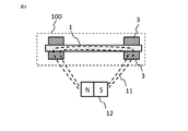
- FIG. 1 shows the configuration of the power generation element 100 according to the first embodiment.
- a power generation coil 2 made of a conductive wire is wound around the magnetic body 1, and a soft magnetic material 3 made of a soft magnetic material is in contact with the periphery of the magnetic body 1 at both ends of the magnetic body 1. It is arranged in a state where it is sandwiched and pressed.
- the magnetic material 1 used in the first embodiment can produce a large Barkhausen effect.
- the large Barkhausen effect is a phenomenon in which when the magnetic body 1 is magnetized, the magnetic domain wall inside the magnetic body 1 moves at once, and the magnetization direction is reversed in an extremely short time.
- a bicaloy alloy FeCoV alloy
- FeCoV alloy FeCoV alloy
- the power generation coil 2 uses a conductive wire and is arranged so as to wind and surround the magnetic body 1.
- the magnetic flux inside the magnetic body 1 changes due to the large Barkhausen effect of the magnetic body 1
- the magnetic flux passing through the power generation coil 2 changes. Therefore, an electromotive force due to electromagnetic induction is generated in the power generation coil 2, and the power generation element 100 can function.
- the power generation coil 2 using the conductive wire a copper wire having an insulating coating can be used, and the wire is formed by winding the wire around the bobbin.
- the wire diameter of the power generation coil 2 was set to 0.02 mm to 0.05 mm.
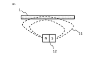
- a magnetic field generation source 12 is arranged around the magnetic body 1. Two magnetic poles, an N pole and an S pole, are used as the magnetic field generation source 12 to generate the magnetic field 11. It is also possible to generate a magnetic field 11 by using one or more sets of two magnetic poles, an N pole and an S pole, as the magnetic field generation source 12. The magnetic field 11 is applied to the magnetic body 1.
- Soft magnetic materials 3 are arranged at both ends of the magnetic material 1.
- the soft magnetic material 3 easily undergoes magnetic pole reversal and the like, and exhibits a higher magnetic permeability and a saturated magnetic flux density than the magnetic material 1 used in the first embodiment.
- FIG. 2 shows a cross-sectional view of a portion of the magnetic body 1 to which the soft magnetic body 3 is attached, cut in a direction orthogonal to the magnetic body 1.
- the block-shaped soft magnetic material 3 is formed with a groove 15 having a V-shaped cross section.
- the magnetic body 1 is arranged at a position determined by fitting with the V-shaped groove 15, and is pressed by two soft magnetic bodies 3 from above and below, that is, a V-shape formed on the soft magnetic body 3.
- the wall surface of the groove 15 is held in a state where the magnetic body 1 is pressed.
- the groove 15 formed in the block-shaped soft magnetic body 3 is formed deeper than the radius of the magnetic body 1.
- the groove 15 is formed and used at a maximum of 0.2 mm deeper than the depth of the radius of the magnetic body 1.
- the soft magnetic body 3 is formed with a groove shape having an inner diameter smaller than the outer diameter of the magnetic body 1 so that the wall surface of the groove 15 presses the magnetic body 1.
- the two block-shaped soft magnetic bodies 3 face each other, and the surfaces of the opposing soft magnetic bodies 3 other than the portion where the groove 15 is formed are in contact with each other.
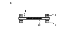
- FIG. 3 to 5 show schematic cross-sectional views of the power generation element 100 cut in the longitudinal direction of each magnetic body 1, and how the magnetic field generated from each magnetic field generation source 12 is inside the magnetic body 1. It shows whether it is distributed in.
- FIG. 3 is a schematic cross-sectional view of the power generation element 100 in which the soft magnetic material 3 is pressed against both ends of the magnetic body 1 and arranged in contact with each other.
- FIG. 5 shows the soft magnetic material 3 at both ends of the magnetic body 1.
- a schematic cross-sectional view of the power generation element 100 in the case where the power generation element 100 is not used is shown.
- FIG. 4 shows an intermediate configuration between these, and although the soft magnetic material 3 is provided at both ends of the magnetic body 1, the magnetic body 1 is not pressed by the soft magnetic material 3 and the gap 18 is formed. It shows the state of having. In addition, in FIGS. 3 to 5, the power generation coil 2 is omitted.
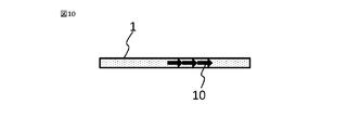
- FIG. 6 shows the distribution of the internal magnetic flux density of the magnetic body 1 of the power generation element 100 shown in FIGS. 3 to 5, and FIG. 7 shows the electromotive force of each. Further, in FIGS. 8 to 10, an arrow 10 indicates a region having a high magnetic flux density inside each magnetic material 1.
- FIG. 6 shows a comparison of the distributions of magnetic flux densities of the magnetic materials 1 of the three types of power generation elements 100 shown in FIGS. 3 to 5.
- the magnetic flux density 8A inside the magnetic body 1 placed by pressing the soft magnetic body 3 and the magnetic flux density 8B when the magnetic body 1 is placed with a gap without being pressed by the soft magnetic body 3 are shown.
- FIG. 6 in order to make it easier to understand the positional relationship between the magnetic material 1 and the distribution of the magnetic flux density, the cross-sectional views of the magnetic material 1 and the soft magnetic material 3 are made to correspond to the data of the magnetic flux density at the upper part of the drawing. Shown.
- the magnetic flux density 8C When the soft magnetic material 3 was not used, the magnetic flux density was high in the central portion of the magnetic body 1 as shown by the magnetic flux density 8C, but when it was out of the central portion, the magnetic flux density decreased sharply toward both ends. Further, in the case where the soft magnetic material 3 does not press the magnetic material 1 and has a gap between them, the soft magnetic material 3 is not used in the range where the magnetic flux density is high, as shown in the magnetic flux density 8B. Although it was wider than the magnetic flux density of 8C in the configuration, it dropped sharply at both ends of the magnetic body 1. It can be seen that the magnetic flux density 8A having the structure in which the magnetic body 1 is pressed against the soft magnetic body 3 has a wider region where the magnetic flux density is higher than the magnetic flux densities 8B and 8C having different arrangements of the soft magnetic body 3.
- FIG. 7 shows the electromotive force when the distribution of the magnetic flux density of the magnetic material 1 corresponds to the magnetic flux densities 8A to 8C shown in FIG.
- the magnetic flux density 8A corresponds to an electromotive force 9A
- the magnetic flux density 8B corresponds to an electromotive force 9B
- the magnetic flux density 8C corresponds to an electromotive force 9C. It can be confirmed that the region having a high magnetic flux density produces the largest electromotive force 9A at the widest magnetic flux density 8A.
- FIG. 8 to 10 schematically show a portion where the magnetic flux density inside the magnetic body 1 is high and the magnetization direction is reversed due to the large Barkhausen effect for three configurations in which the soft magnetic material 3 is arranged differently. It is shown by.
- FIG. 8 shows a configuration in which the soft magnetic material 3 is pressed and arranged, which is shown in a schematic cross-sectional view in FIG. It is shown that the reversal of the magnetization direction due to the Barkhaus effect occurs stably in the entire magnetic material 1. Therefore, in the power generation element having this configuration, the electromotive force of the power generation coil 2 due to electromagnetic induction is also stable and large.
- FIG. 9 shows a configuration in which the magnetic material 1 and the soft magnetic material 3 shown in FIG. 4 have voids
- FIG. 10 shows a configuration in which the soft magnetic material 3 shown in FIG. 5 is not used.
- the arrows 10 are distributed only in a part of the magnetic material 1, and the large Barkhausen effect occurs only in a part of the magnetic material 1. Therefore, it can be seen that the reversal of the magnetization direction becomes unstable and sufficient power generation characteristics cannot be obtained as the power generation element 100.
- the power generation element 100 of the first embodiment will be described together with configurations and materials that can be used in addition to the configurations and materials described so far.
- a permalloy alloy NiFe alloy
- an amorphous alloy or the like can be used in addition to the bicaloy alloy.
- surface treatment such as bending, heat treatment and plating, and chemical treatment can be used.
- the coercive force can also be controlled by adding additives to these alloy materials.
- the shape of the magnetic body 1 is a wire shape in the first embodiment, but as shown in FIG. 11, even a sheet-shaped magnetic body 22 can be used by winding the power generation coil 2.
- a wire diameter of 0.1 mm to 1 mm was used for the magnetic material 1, but the present invention is not limited to this, and a wire diameter of less than 0.1 mm and a wire diameter thicker than 1 mm can be used.
- the magnetic material 1 having a circular cross-sectional shape is used, but the present invention is not limited to this, and it can also be used as a polygon such as a quadrangle or a thin flat plate. ..
- the coercive force of the outer peripheral portion of the magnetic body 1 is smaller than that of the central portion, the coercive force of the outer peripheral portion and the central portion may be different, and the coercive force of the outer peripheral portion is larger. Can be used in the same manner.
- the material used for the soft magnetic material 3 a cold-rolled steel sheet is suitable because it can be processed into a desired shape with high accuracy and is inexpensive.
- the soft magnetic material 3 having a higher magnetic permeability and saturation magnetic flux density than the magnetic material 1 may be used, and soft ferrite, permalloy, permendur, silicon steel, amorphous magnetic alloy, nanocrystal magnetic alloy, and sendust may also be used. Can be done.
- the soft magnetic material can be processed into particles and contained in a plastic material or the like for use.
- the soft magnetic material 3 using this plastic material has a feature that it can be easily formed into various shapes by injection molding or the like.
- a block-shaped soft magnetic body 3 having a V-shaped groove 15 formed therein is used vertically, but the cross-sectional shape of the groove 15 is fitted with the magnetic body 1.
- the magnetic body 1 can be arranged at a predetermined position, a quadrangle, a semicircular shape, and a semi-elliptical shape can be used in addition to the V-shape.
- the groove 15 is not always necessary, and even if the soft magnetic material 3 does not form the groove 15, as shown in FIG.
- the magnetic material 1 And the position of the soft magnetic body 3 is arranged at a predetermined position by the jig P, and the adhesive 16 is applied and cured to form the magnetic body 1 into two soft magnetic bodies as shown in FIG. 12 (b). It can be stably held on the flat surface of the body 3.
- the type of adhesive that adheres the two soft magnetic materials 3 arranged one above the other to each other is not particularly limited, but the anaerobic curing type or the anaerobic curing type is used because the adhesive is easy to handle and the curing time is short.
- a curable adhesive that is a combination of an anaerobic curable type and other curable types is suitable.
- a heat-curing type, a curing agent mixed type, an ultraviolet curing type, a heat-melting type, or an adhesive in which these curing methods are combined can also be used.
- the two soft magnetic bodies 3 can be pressed and held against each other.
- the soft magnetic material 3 can be joined by caulking.
- adhesive tape, press fitting, rivet joining, pressure welding, welding, brazing, snap fit and the like can be used.
- the power generating coil 2 uses a conductive wire of a copper wire having an insulating coating, but it is sufficient if the same conductivity can be ensured, and an aluminum wire, gold, silver, or a copper alloy is used. , Aluminum alloys can also be used. Further, for the power generation coil 2, a wire having a wire diameter of 0.02 mm to 0.05 mm was used as the conductive wire, but the present invention is not limited to this, and the diameter of the magnetic body 1 to be wound and the power generation element are not limited to this. The wire diameter of the conductive wire constituting the power generation coil 2 can be selected based on the size of 100 or the like.
- a conductive wire was wound around a bobbin to form the power generation coil 2, but the present invention is not limited to this. It is also possible to wind a conductive wire around the jig and tool, fix it with an adhesive and a self-bonding wire, remove it from the jig and tool, and use it as a power generation coil 2.
- the power generation coil 2 is preferably arranged so as to surround the magnetic body 1 so that the change in magnetic flux due to the large Barkhausen effect of the magnetic body 1 is maximized.
- the magnetic field 17 generated by the magnetic body 1 does not surround the magnetic body 1 so as to pass through the power generation coil 2 along the magnetic body 1. It may be arranged.
- a permanent magnet As the magnetic field generation source 12. However, it suffices to stably generate the magnetic field 11, and even an electromagnet can be used.
- the permanent magnet rare earth magnets such as ferrite magnets, neodymium magnets, alnico magnets, and samarium-cobalt magnets can be used. Further, it is also possible to contain magnetic material particles in a plastic material and mold it by injection molding or the like to use it as a magnet.
- FIG. 1 As a configuration of the power generation element, as shown in FIG. 1, a case where a power generation element 100 composed of a magnetic material 1, a power generation coil 2 and a soft magnetic material 3 is paired with one magnetic field generation source 12 is shown. However, as shown in FIG. 14, three sets of power generation elements 100a, 100b, and 100c may be arranged with respect to one magnetic field generation source 12A.
- the magnetic field generation source 12A has a disk shape, and power generation elements 100a to 100c are arranged above the magnetic field generation source 12A at intervals from the magnetic field generation source 12A.
- the magnetic field generation source 12A rotates about the point O. Note that FIG. 14 is an example of the arrangement method, and the present invention is not limited to this.
- the electromotive force generated in the power generation element 100 can be used as a power source for driving the IC.
- a magnetic sensor that notifies the generation of the magnetic field 11 by a pulse voltage by utilizing the fact that the fluctuation of the magnetic field 11 caused by the large bulkhausen effect is steep and the electric power generated from the power generation coil 2 by electromagnetic induction becomes a pulse shape. Can be used.
- the IC 23 uses the characteristics of stable power supply and pulse of the power generation element 100, as shown in FIG. 15, the IC 23 operates by combining the power generation element 100 with the IC 23 and the like and using the power generated in a pulse shape by the power generation element 100 as a power source.
- a non-powered magnetic sensor 50 for detecting the generation of a pulse of the power generation element 100 with the IC 23, and a reflective optical encoder 200 whose cross-sectional schematic diagram is shown in FIG. 16 can also be obtained.
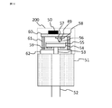
- FIG. 16 is a schematic view showing a cross-sectional configuration of the reflective optical encoder 200.
- the reflective optical encoder 200 is attached to the motor 51.
- a rotary shaft 53 is coaxially connected to the motor rotary shaft 52 of the motor 51, and a hub member 54 to which a disk-shaped scale plate 55 is attached is fixed to the rotary shaft 53.
- the substrate 60, the housing 61 arranged around it, and the housing 62 through which the rotating shaft 53 penetrates cover the periphery of the scale plate 55, and the non-powered magnetic sensor 50 is applied to the outer surface of the substrate 60, and the irradiation light indicated by the arrow 49 is applied to the inner surface.
- a light emitting unit 57 that emits light and a light receiving unit 58 that receives the reflected light indicated by the arrow 56 are arranged.
- Magnetism is applied to the hub member 54.
- a magnet 59 is fixed to the back surface of the hub member 54 in order to impart magnetism to the hub member 54. Further, the magnet 59 can be arranged between the disk-shaped scale plate 55 and the hub member 54. In this case, the step of fixing the hub member 54 and the magnet 59 can be omitted, and the production efficiency can be improved. Further, by molding the magnet 59 into the shape of the hub member 54, since the magnet 59 has the function of the hub member 54, the number of constituent parts can be reduced and the production efficiency can be improved.
- the material of the hub member 54 can be formed by dispersing magnetic particles in a plastic material or the like, and the hub member 54 can be easily formed into various shapes by injection molding.
- the hub member 54 is not limited to the configuration in which magnetic particles are dispersed in a plastic material or the like, and may be formed of ferrite, alnico (Al—Ni—Co), or a rare earth element.
- the reflective optical encoder 200 when the rotating shaft 53 is rotated, the irradiation light emitted from the light projecting portion 57 is transmitted by a high-reflecting portion having a high light reflectance and a low-reflecting portion having a low light reflectance formed on the scale plate 55.
- the rotation angle and the rotation speed are detected by reflecting the light in the configured pattern and detecting the change in the amount of the reflected light by the light receiving unit 58.
- the power generation element 100 generates power by changing the direction of the magnetic force emitted from the hub member 54, thereby detecting the number of rotations rotated from the reference position.
- the reflective optical encoder 200 detects the rotation angle, the number of rotations, and the rotation speed of the rotating shaft 53 to determine the rotation angle and the number of rotations of the motor 51.
- the rotation speed can be detected.
- Embodiment 2 The basic structure of the power generation element 100 according to the second embodiment is the same as that of the first embodiment, and the structure in which the magnetic body 1 is pressed and arranged by the soft magnetic body 3 is different.
- FIG. 17 shows a cross-sectional view of a portion of the power generation element 100 in which the soft magnetic body 4 is attached to the magnetic body 1 cut in a direction orthogonal to the magnetic body 1.
- the two block-shaped soft magnetic materials 3 were pressed against each other and held, but the soft magnetic material shown in FIG. 17 was held.
- the magnetic material 1 is pressed by the block-shaped soft magnetic material 4 having the groove 15 formed and the block-shaped non-magnetic material 20 having the groove 15 formed in the same manner as the soft magnetic material 4, and the magnetic material 1 is softened.
- the magnetic material 4 and the non-magnetic material 20 are fixed and held by the adhesive 16.
- the shape of the groove 15 and the type of the adhesive 16 can be used as long as the soft magnetic body 4 has a shape and a material that can press and hold the magnetic body 1 as in the first embodiment. ..
- the non-magnetic material 20 and the soft magnetic material 4 press and hold the magnetic material 1 so that the magnetic material 1 and the soft magnetic material 4 can be stably brought into contact with each other due to the large Barkhausen effect generated by the magnetic material 1. It is possible to stabilize the change in the magnetization direction and obtain power generation characteristics with little fluctuation. Further, the power generation element 100 can be applied to a magnetic sensor and an encoder.
- Embodiment 3 The basic structure of the power generation element 100 according to the third embodiment is the same as that of the first embodiment, and the structure in which the magnetic body 1 is pressed and arranged by the soft magnetic body 3 is different.
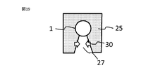
- FIG. 18 shows a cross-sectional view of a portion of the power generation element 100 in which the soft magnetic body 24 is attached to the magnetic body 1 cut in a direction orthogonal to the magnetic body 1.
- the two block-shaped soft magnetic materials 3 are pressed against each other and held, but the soft magnetic material shown in FIG. 18 is held.
- a U-shaped soft magnetic material 24 is used, and the magnetic material 1 is pressed against the fitting groove 27, which is an inner portion of the U-shape, to be fixed and held.
- the inner diameter of the inner bottom portion of the U-shape is formed to be equal to or smaller than the outer diameter of the magnetic body 1, and the distance between both ends of the tip portion of the U-shape is formed to be smaller than the diameter of the bottom portion.
- the fitting groove 27 expands, and after the fitting, the magnetic body 1 is schematically indicated by the arrow 30 by the elastic force of the soft magnetic body 24. Press as if.
- the fitting groove 27 can be used as long as it has a shape and a material that the soft magnetic material 24 can press and hold the magnetic material 1.
- the block-shaped soft magnetic material 25 can also be used by forming the fitting groove 27.
- the inner diameter of the bottom of the fitting groove 27 is formed to be smaller than the outer diameter of the magnetic body 1.
- the soft magnetic bodies 24 and 25 press and hold the magnetic body 1 as shown by the arrow 30, so that the magnetic body 1 and the soft magnetic bodies 24 and 25 can be stably brought into contact with each other. Therefore, it is possible to stabilize the change in the magnetization direction due to the large Barkhausen effect generated in the magnetic material 1 and obtain power generation characteristics with little change. Further, the power generation element 100 can be applied to a magnetic sensor and an encoder.
- Embodiment 4 The basic structure of the power generation element 100 according to the fourth embodiment is the same as that of the first embodiment, and the structure in which the magnetic body 1 is pressed and arranged by the soft magnetic body 3 is different.
- FIG. 20 shows a cross-sectional view of a portion of the power generation element 100 in which the soft magnetic body 4 is attached to the magnetic body 1 cut in a direction orthogonal to the magnetic body 1.
- the two block-shaped soft magnetic materials 3 were pressed against each other and held, but the soft magnetic material shown in FIG. 20 was held.
- the magnetic body 1 is pressed, fixed and held by the block-shaped soft magnetic material 4 having the groove 15 formed and the adhesive 21.
- the shape of the groove 15 and the type of the adhesive 21 can be used as long as the soft magnetic body 4 has a shape and a material that can press and hold the magnetic body 1 as in the first embodiment. ..
- the adhesive 21 when the adhesive 21 is cured, it shrinks and the magnetic material 1 can be pressed against the groove wall surface of the soft magnetic material 4. As shown in FIG.
- the magnetic material 1 was pressed against the soft magnetic material 4 by applying the adhesive 21 and curing the magnetic material 1 against the soft magnetic material 4 with the jig Q. It may be held in a state. Further, as shown in FIG. 22, a structure in which an fitting groove 27, which is an inner portion of the U-shape, is formed in the U-shaped soft magnetic body 26, and the fitted magnetic body 1 is held by the adhesive 21 and pressed. It may be.
- the soft magnetic bodies 4 and 26 press and hold the magnetic body 1, so that the magnetic body 1 and the soft magnetic bodies 4 and 26 can be stably brought into contact with each other, and a large bulk generated by the magnetic body 1 can be obtained. It is possible to stabilize the change in the magnetization direction due to the Barkhaus effect and obtain power generation characteristics with little fluctuation. Further, the power generation element 100 can be applied to a magnetic sensor and an encoder.
- Embodiment 5 The basic structure of the power generation element 100 according to the fifth embodiment is the same as that of the first embodiment, and the attachment structure of the soft magnetic body 3 to the magnetic body 1 is different.
- FIG. 23 shows a perspective view illustrating a portion where the soft magnetic body 5 is arranged on the magnetic body 1 of the power generation element 100.
- the soft magnetic material 5 has a cylindrical shape and is provided with an insertion hole 13 penetrating between the circular upper surface and the bottom surface.
- a magnetic body 1 that produces a large Barkhausen effect is press-fitted into the insertion hole 13, and the magnetic body 1 is pressed and fixed by the cylindrical soft magnetic body 5.
- FIG. 24 shows the cross-sectional structure of the cylindrical soft magnetic material 5 provided with the insertion hole 13 shown in FIG. 23 when it is divided from the upper surface to the bottom surface along the insertion hole 13.
- tapered portions 14 are formed on the upper surface side and the bottom surface side of the insertion hole 13 of the soft magnetic material 5 so that the opening portion increases outward from the central portion of the insertion hole 13.
- the outer diameter of the magnetic body 1 is formed larger than the inner diameter of the insertion hole 13 formed in the soft magnetic body 5.
- the fitting tolerance which is the difference between the inner diameter of the insertion hole 13 of the soft magnetic body 5 and the outer diameter of the magnetic body 1, should be +50 micron or less in terms of workability and fixing strength by pressing. Preferred from the point of view.
- the magnetic body 1 By press-fitting the magnetic body 1 into the insertion hole 13 of the soft magnetic body 5, the magnetic body 1 can be pressed and arranged by tight fitting.
- the tight fitting step not only press fitting but also shrink fitting or the like in which the insertion hole 13 is heated and expanded to fit the magnetic material 1 can be used.
- the soft magnetic body 5 and the magnetic body 1 are brought into contact with each other by pressing the magnetic body 1 from the fitting, and the magnetic resistance between the magnetic body 1 and the soft magnetic body 5 is increased. It can be made smaller. Therefore, the magnetic field 11 can be stably applied to the magnetic body 1 by the magnetic field generation source 12. As a result, the change in the magnetization direction due to the large Barkhausen effect is stable, and the electromotive force can be stably generated in the power generation coil 2 by electromagnetic induction.
- the tapered portion 14 in the insertion hole 13 of the soft magnetic material 5 as described above in order to efficiently perform the insertion work.
- the efficiency of the insertion work by press fitting can be improved, and a power generation element capable of stably generating an electromotive force can be obtained.
- the power generation element 100 can be applied to a magnetic sensor and an encoder.
- the soft magnetic material 6 used in the sixth embodiment is not only composed of a soft magnetic material made of soft ferrite, permalloy, etc., but is made of soft magnetic material particles obtained by finely processing the soft magnetic material into particles, such as an adhesive. It is characterized by being added to the plastic material of.
- FIG. 25 shows a schematic diagram of the power generation element 120 of the sixth embodiment.
- the basic configuration is the same as that of the first embodiment, in which a power generation coil 2 made of a conductive wire is arranged around the magnetic body 1, and soft magnetic materials 6 are attached to both ends of the magnetic body 1. ing.
- the soft magnetic material 6 is made by processing soft ferrite to a particle size of 5 microns or less and adding it to a plastic material.
- the plastic material to which the soft ferrite particles are added can be processed into a shape that can be attached to both ends of the magnetic body 1 by a molding apparatus. For example, by forming a cylindrical shape having an insertion hole 13 similar to the soft magnetic body 5 of FIG. 23 described in the fifth embodiment, it can be easily attached to both ends of the magnetic body 1.
- soft ferrite is used as the particulate soft magnetic material to be added to the plastic material, but the present invention is not limited to this, and any material that can be processed into particles is used in the same manner. Permalloy, silicon steel, etc. can be used.
- a heat-curing type, a curing agent mixed type, an ultraviolet curing type, an anaerobic curing type, a heat-melting type, or a composite curing type plastic material thereof is used.
- a heat-curing type, a curing agent mixed type, an ultraviolet curing type, an anaerobic curing type, a heat-melting type, or a composite curing type plastic material thereof is used.
- an ultraviolet curable type or a composite plastic material of another curable type and an ultraviolet curable type, which has a short time to cure is suitable.
- a plastic material to which a particulate soft magnetic material is added is molded to obtain a soft magnetic material 6, which is fitted to both ends of the magnetic material 1 without any gaps. Since the magnetic material 1 that produces the large bulkhausen effect is pressed and contacted by the soft magnetic material 6, the magnetic field 11 can be stably applied to the magnetic material 1, and the change in the magnetization direction due to the large bulkhausen effect is stable. By electromagnetic induction, the electromotive force can be stably generated in the power generation coil 2. Further, the power generation element 120 can be applied to a magnetic sensor and an encoder.
- Embodiment 7 In the power generation element 130 of the seventh embodiment, as shown in the schematic view of FIG. 26, the soft magnetic material 7 is used by forming a wire from a soft magnetic material such as soft ferrite or permalloy and winding it around the magnetic material 1. It is a feature. In the processing of the soft magnetic body 7, the inner diameter of the wound soft magnetic body 7 is formed to be smaller than the outer diameter of the magnetic body 1, so that when the soft magnetic body 7 is attached to the magnetic body 1, the soft magnetic body 7 presses and arranges the soft magnetic body 7. be able to.
- a soft magnetic material such as soft ferrite or permalloy
- the wound soft magnetic body 7 presses and arranges the magnetic body 1 that produces a large Barkhausen effect
- the magnetic resistance between the soft magnetic body 7 and the magnetic body 1 can be kept small, and a magnetic field is generated.
- the magnetic field 11 of the source 12 can be stably applied to the magnetic material 1. Therefore, the change in the magnetization direction due to the large Barkhausen effect is stabilized, and a stable electromotive force can be generated in the power generation coil 2 by electromagnetic induction.
- the power generation element 100 can be applied to a magnetic sensor and an encoder.
- the block-shaped soft magnetic material 3 when heat is applied to the power generation elements 100, 110, 120 from the outside and the magnetic material 1 becomes hot, the block-shaped soft magnetic material 3, etc.
- the thermal expansion coefficient of the magnetic body 1 is significantly different from that of the magnetic body 1, a large stress is applied to the magnetic body 1 at a high temperature, and the magnetic characteristics of the magnetic body 1 change. As a result, the change in the magnetization direction due to the large Barkhausen effect may be small.
- the soft magnetic material 7 When the soft magnetic material 7 is wound and used as in the seventh embodiment, even if there is a difference in the coefficient of thermal expansion between the soft magnetic material 7 and the magnetic material 1, even at a high temperature, the magnetic material 1 is transferred to the magnetic material 1. The stress can be reduced. Therefore, since the soft magnetic body 7 can be pressed and held by the magnetic body 1, the magnetic resistance can be reduced and the stable magnetic field 11 can be passed through the magnetic body 1, and the power generation coil 2 can be used. A stable electromotive force can be generated. Further, the power generation element 130 can be applied to a magnetic sensor and an encoder.
Abstract
La présente invention concerne un corps magnétique qui présente un effet Barkhausen important, une bobine de génération d'énergie disposée de manière à être enroulée autour du corps magnétique, et un corps magnétique doux qui est formé sur les deux extrémités du corps magnétique de façon à être en contact avec le corps magnétique et à presser le corps magnétique. En conséquence, la présente invention améliore l'uniformité de la densité du flux magnétique du corps magnétique et produit de façon stable un effet Barkhausen important de telle sorte qu'un élément de génération d'énergie hautement stable est obtenu.
Priority Applications (3)
| Application Number | Priority Date | Filing Date | Title |
|---|---|---|---|
| CN202180023746.2A CN115335716A (zh) | 2020-04-01 | 2021-03-23 | 发电元件、使用其的磁传感器、编码器以及马达 |
| JP2022511970A JP7378586B2 (ja) | 2020-04-01 | 2021-03-23 | 発電素子、これを用いた磁気センサ、エンコーダおよびモータ |
| US17/800,242 US20230068474A1 (en) | 2020-04-01 | 2021-03-23 | Power generation element, and magnetic sensor, encoder, and motor using the same |
Applications Claiming Priority (2)
| Application Number | Priority Date | Filing Date | Title |
|---|---|---|---|
| JP2020-065516 | 2020-04-01 | ||
| JP2020065516 | 2020-04-01 |
Publications (1)
| Publication Number | Publication Date |
|---|---|
| WO2021200361A1 true WO2021200361A1 (fr) | 2021-10-07 |
Family
ID=77927472
Family Applications (1)
| Application Number | Title | Priority Date | Filing Date |
|---|---|---|---|
| PCT/JP2021/011846 WO2021200361A1 (fr) | 2020-04-01 | 2021-03-23 | Élément de génération d'énergie, capteur magnétique le mettant en œuvre, codeur et moteur |
Country Status (4)
| Country | Link |
|---|---|
| US (1) | US20230068474A1 (fr) |
| JP (1) | JP7378586B2 (fr) |
| CN (1) | CN115335716A (fr) |
| WO (1) | WO2021200361A1 (fr) |
Cited By (3)
| Publication number | Priority date | Publication date | Assignee | Title |
|---|---|---|---|---|
| WO2022153861A1 (fr) * | 2021-01-12 | 2022-07-21 | 三菱電機株式会社 | Élément de génération d'énergie, capteur magnétique, codeur et moteur |
| WO2024004423A1 (fr) * | 2022-06-28 | 2024-01-04 | パナソニックIpマネジメント株式会社 | Élément de génération d'énergie électrique, capteur magnétique et codeur |
| JP7471519B2 (ja) | 2021-05-18 | 2024-04-19 | 三菱電機株式会社 | 発電モジュール |
Citations (8)
| Publication number | Priority date | Publication date | Assignee | Title |
|---|---|---|---|---|
| JPS5450373A (en) * | 1978-08-07 | 1979-04-20 | Akira Matsushita | Magnetismmsensitive element |
| JPH11195964A (ja) * | 1997-12-26 | 1999-07-21 | Hirose Cherry Precision:Kk | パルス信号発生装置 |
| JP2006073974A (ja) * | 2004-09-03 | 2006-03-16 | Taiji Takemura | 磁気センサ |
| WO2013094042A1 (fr) * | 2011-12-21 | 2013-06-27 | 株式会社安川電機 | Moteur, système de moteur, et encodeur de moteur |
| JP2014171044A (ja) * | 2013-03-01 | 2014-09-18 | Yokohama National Univ | 電気パルス発生装置、及び電気パルス発生装方法 |
| WO2016170648A1 (fr) * | 2015-04-23 | 2016-10-27 | 三菱電機株式会社 | Dispositif de détection de rotation et procédé de fabrication d'un dispositif de détection de rotation |
| JP2016208817A (ja) * | 2015-04-17 | 2016-12-08 | 信越化学工業株式会社 | アキシャルギャップ型回転機 |
| JP6647478B1 (ja) * | 2019-06-14 | 2020-02-14 | 三菱電機株式会社 | 回転数検出器 |
Family Cites Families (11)
| Publication number | Priority date | Publication date | Assignee | Title |
|---|---|---|---|---|
| JPH04218905A (ja) * | 1990-03-23 | 1992-08-10 | Unitika Ltd | 薄膜状磁性材料及びその製造方法 |
| JP5132210B2 (ja) * | 2007-07-09 | 2013-01-30 | キヤノン株式会社 | 磁気検出素子及び検出方法 |
| US8030786B2 (en) * | 2008-08-22 | 2011-10-04 | Willowview Systems, Inc. | System for generating electrical energy from ambient energy |
| JP5341854B2 (ja) * | 2010-09-30 | 2013-11-13 | 株式会社東芝 | 永久磁石モータおよび洗濯機 |
| JP5450373B2 (ja) | 2010-12-27 | 2014-03-26 | 株式会社サイカワ | 環状波付け装置 |
| US9494556B2 (en) * | 2012-01-13 | 2016-11-15 | Polyresearch Ag | Active mechanical force and axial load sensor |
| JP5769879B2 (ja) | 2012-04-17 | 2015-08-26 | 三菱電機株式会社 | 多回転エンコーダ |
| CN104813570A (zh) * | 2012-12-14 | 2015-07-29 | 武汉领普科技有限公司 | 永磁发电装置 |
| WO2016067575A1 (fr) * | 2014-10-31 | 2016-05-06 | パナソニックIpマネジメント株式会社 | Dispositif de détection de matière étrangère |
| JPWO2018097110A1 (ja) * | 2016-11-28 | 2019-10-17 | 日本電産株式会社 | 発電素子、およびスマートキー |
| WO2022153356A1 (fr) | 2021-01-12 | 2022-07-21 | 三菱電機株式会社 | Élément de production d'énergie, capteur magnétique et codeur |
-
2021
- 2021-03-23 CN CN202180023746.2A patent/CN115335716A/zh active Pending
- 2021-03-23 US US17/800,242 patent/US20230068474A1/en active Pending
- 2021-03-23 WO PCT/JP2021/011846 patent/WO2021200361A1/fr active Application Filing
- 2021-03-23 JP JP2022511970A patent/JP7378586B2/ja active Active
Patent Citations (8)
| Publication number | Priority date | Publication date | Assignee | Title |
|---|---|---|---|---|
| JPS5450373A (en) * | 1978-08-07 | 1979-04-20 | Akira Matsushita | Magnetismmsensitive element |
| JPH11195964A (ja) * | 1997-12-26 | 1999-07-21 | Hirose Cherry Precision:Kk | パルス信号発生装置 |
| JP2006073974A (ja) * | 2004-09-03 | 2006-03-16 | Taiji Takemura | 磁気センサ |
| WO2013094042A1 (fr) * | 2011-12-21 | 2013-06-27 | 株式会社安川電機 | Moteur, système de moteur, et encodeur de moteur |
| JP2014171044A (ja) * | 2013-03-01 | 2014-09-18 | Yokohama National Univ | 電気パルス発生装置、及び電気パルス発生装方法 |
| JP2016208817A (ja) * | 2015-04-17 | 2016-12-08 | 信越化学工業株式会社 | アキシャルギャップ型回転機 |
| WO2016170648A1 (fr) * | 2015-04-23 | 2016-10-27 | 三菱電機株式会社 | Dispositif de détection de rotation et procédé de fabrication d'un dispositif de détection de rotation |
| JP6647478B1 (ja) * | 2019-06-14 | 2020-02-14 | 三菱電機株式会社 | 回転数検出器 |
Cited By (5)
| Publication number | Priority date | Publication date | Assignee | Title |
|---|---|---|---|---|
| WO2022153861A1 (fr) * | 2021-01-12 | 2022-07-21 | 三菱電機株式会社 | Élément de génération d'énergie, capteur magnétique, codeur et moteur |
| JP7109713B1 (ja) * | 2021-01-12 | 2022-07-29 | 三菱電機株式会社 | 発電素子、磁気センサ、エンコーダおよびモータ |
| US11913813B2 (en) | 2021-01-12 | 2024-02-27 | Mitsubishi Electric Corporation | Power generation element, magnetic sensor, encoder, and motor |
| JP7471519B2 (ja) | 2021-05-18 | 2024-04-19 | 三菱電機株式会社 | 発電モジュール |
| WO2024004423A1 (fr) * | 2022-06-28 | 2024-01-04 | パナソニックIpマネジメント株式会社 | Élément de génération d'énergie électrique, capteur magnétique et codeur |
Also Published As
| Publication number | Publication date |
|---|---|
| CN115335716A (zh) | 2022-11-11 |
| JP7378586B2 (ja) | 2023-11-13 |
| JPWO2021200361A1 (fr) | 2021-10-07 |
| US20230068474A1 (en) | 2023-03-02 |
Similar Documents
| Publication | Publication Date | Title |
|---|---|---|
| WO2021200361A1 (fr) | Élément de génération d'énergie, capteur magnétique le mettant en œuvre, codeur et moteur | |
| JP3199813B2 (ja) | 可動磁石検流計及び高周波光学スキャナ・トルク・モータ | |
| JP5614501B2 (ja) | 回転電機用ロータ、回転電機、および、回転電機用ロータの製造方法 | |
| JP2007110822A (ja) | 周期磁界発生装置とその製造方法およびこの周期磁界発生装置を用いたリニアモータ | |
| WO2005008862A1 (fr) | Aimant annulaire fin pour magnetisation hybride, aimant annulaire fin pour magnetisation hybride equipe d'une culasse, et moteur sans balais | |
| JP2003199274A (ja) | 回転子とその製造法及び回転機 | |
| JP2015133839A (ja) | 磁石埋込型ロータ | |
| JP3249930B2 (ja) | 挿入光源 | |
| JP2007214393A (ja) | リング状の極異方性プラスチック磁石及びモータ用ロータ | |
| JP4029679B2 (ja) | モータ用ボンド磁石及びモータ | |
| JP7109713B1 (ja) | 発電素子、磁気センサ、エンコーダおよびモータ | |
| US20070205672A1 (en) | Linear Motor And Manufacturing Method Of Linear Motor | |
| JP3664271B2 (ja) | 多極着磁用ヨーク | |
| JPH06303752A (ja) | ブラシレスモータの位置検出用磁気回路 | |
| JPS5927508A (ja) | 着磁方法 | |
| JP2001339885A (ja) | 電動機の永久磁石回転子 | |
| JP6947340B1 (ja) | 界磁子および界磁子を備えた電動機 | |
| JP2005223233A (ja) | 極異方性円筒状磁石成形用金型 | |
| JP7394428B1 (ja) | ブラシレスspmモータおよびその回転子の製造方法 | |
| JP2005312166A (ja) | 4磁極モータ用異方性ボンド磁石及びそれを用いたモータ | |
| JP4013916B2 (ja) | 4磁極モータ用異方性ボンド磁石の配向処理装置 | |
| JPS6329811B2 (fr) | ||
| KR100252831B1 (ko) | 전동기에 설치되는 영구자석의 착자방법 | |
| JP4737202B2 (ja) | モータ用異方性ボンド磁石の配向処理方法 | |
| JPH03203539A (ja) | ステッピングモータ |
Legal Events
| Date | Code | Title | Description |
|---|---|---|---|
| 121 | Ep: the epo has been informed by wipo that ep was designated in this application |
Ref document number: 21781611 Country of ref document: EP Kind code of ref document: A1 |
|
| ENP | Entry into the national phase |
Ref document number: 2022511970 Country of ref document: JP Kind code of ref document: A |
|
| NENP | Non-entry into the national phase |
Ref country code: DE |
|
| 122 | Ep: pct application non-entry in european phase |
Ref document number: 21781611 Country of ref document: EP Kind code of ref document: A1 |