WO2021187595A1 - 自己粘着シート - Google Patents
自己粘着シート Download PDFInfo
- Publication number
- WO2021187595A1 WO2021187595A1 PCT/JP2021/011183 JP2021011183W WO2021187595A1 WO 2021187595 A1 WO2021187595 A1 WO 2021187595A1 JP 2021011183 W JP2021011183 W JP 2021011183W WO 2021187595 A1 WO2021187595 A1 WO 2021187595A1
- Authority
- WO
- WIPO (PCT)
- Prior art keywords
- self
- adhesive sheet
- adhesive
- methyl
- pentene
- Prior art date
Links
- 239000000853 adhesive Substances 0.000 title claims abstract description 498
- WSSSPWUEQFSQQG-UHFFFAOYSA-N dimethylbutene Natural products CC(C)CC=C WSSSPWUEQFSQQG-UHFFFAOYSA-N 0.000 claims abstract description 241
- 229920005989 resin Polymers 0.000 claims description 120
- 239000011347 resin Substances 0.000 claims description 120
- 229920000642 polymer Polymers 0.000 claims description 108
- 238000007789 sealing Methods 0.000 claims description 90
- 239000000463 material Substances 0.000 claims description 78
- 239000004711 α-olefin Substances 0.000 claims description 65
- 238000005259 measurement Methods 0.000 claims description 39
- 125000004432 carbon atom Chemical group C* 0.000 claims description 31
- 238000004806 packaging method and process Methods 0.000 claims description 24
- 239000005022 packaging material Substances 0.000 claims description 19
- 238000010438 heat treatment Methods 0.000 claims description 7
- 238000004891 communication Methods 0.000 claims description 3
- 241000264877 Hippospongia communis Species 0.000 claims 1
- 229920001577 copolymer Polymers 0.000 abstract description 15
- 230000001070 adhesive effect Effects 0.000 abstract description 14
- 238000000034 method Methods 0.000 description 68
- 230000000149 penetrating effect Effects 0.000 description 48
- -1 Cyclic olefins Chemical class 0.000 description 46
- 239000010410 layer Substances 0.000 description 31
- 229920000089 Cyclic olefin copolymer Polymers 0.000 description 29
- 229920001971 elastomer Polymers 0.000 description 28
- 238000001125 extrusion Methods 0.000 description 25
- 238000000465 moulding Methods 0.000 description 24
- VXNZUUAINFGPBY-UHFFFAOYSA-N 1-Butene Chemical compound CCC=C VXNZUUAINFGPBY-UHFFFAOYSA-N 0.000 description 22
- VGGSQFUCUMXWEO-UHFFFAOYSA-N Ethene Chemical compound C=C VGGSQFUCUMXWEO-UHFFFAOYSA-N 0.000 description 22
- PPBRXRYQALVLMV-UHFFFAOYSA-N Styrene Chemical compound C=CC1=CC=CC=C1 PPBRXRYQALVLMV-UHFFFAOYSA-N 0.000 description 22
- 238000002834 transmittance Methods 0.000 description 22
- 239000000470 constituent Substances 0.000 description 21
- 239000005977 Ethylene Substances 0.000 description 20
- 230000000052 comparative effect Effects 0.000 description 18
- 125000004805 propylene group Chemical group [H]C([H])([H])C([H])([*:1])C([H])([H])[*:2] 0.000 description 18
- XLYOFNOQVPJJNP-UHFFFAOYSA-N water Substances O XLYOFNOQVPJJNP-UHFFFAOYSA-N 0.000 description 18
- 239000000806 elastomer Substances 0.000 description 17
- 239000006260 foam Substances 0.000 description 17
- QQONPFPTGQHPMA-UHFFFAOYSA-N propylene Natural products CC=C QQONPFPTGQHPMA-UHFFFAOYSA-N 0.000 description 17
- 229920002725 thermoplastic elastomer Polymers 0.000 description 17
- 238000004519 manufacturing process Methods 0.000 description 16
- 239000004088 foaming agent Substances 0.000 description 14
- 230000003746 surface roughness Effects 0.000 description 14
- 239000004743 Polypropylene Substances 0.000 description 13
- 229920001155 polypropylene Polymers 0.000 description 13
- 239000005060 rubber Substances 0.000 description 13
- 150000001336 alkenes Chemical class 0.000 description 12
- JRZJOMJEPLMPRA-UHFFFAOYSA-N olefin Natural products CCCCCCCC=C JRZJOMJEPLMPRA-UHFFFAOYSA-N 0.000 description 12
- 238000012360 testing method Methods 0.000 description 12
- 230000033001 locomotion Effects 0.000 description 11
- 229920001684 low density polyethylene Polymers 0.000 description 11
- 239000004702 low-density polyethylene Substances 0.000 description 11
- 239000003921 oil Substances 0.000 description 11
- YWAKXRMUMFPDSH-UHFFFAOYSA-N pentene Chemical compound CCCC=C YWAKXRMUMFPDSH-UHFFFAOYSA-N 0.000 description 11
- 229920000139 polyethylene terephthalate Polymers 0.000 description 11
- 239000005020 polyethylene terephthalate Substances 0.000 description 11
- 229920002554 vinyl polymer Polymers 0.000 description 11
- 238000001816 cooling Methods 0.000 description 10
- NNBZCPXTIHJBJL-UHFFFAOYSA-N decalin Chemical compound C1CCCC2CCCCC21 NNBZCPXTIHJBJL-UHFFFAOYSA-N 0.000 description 10
- 239000011342 resin composition Substances 0.000 description 10
- 238000004132 cross linking Methods 0.000 description 9
- 239000000203 mixture Substances 0.000 description 9
- 238000012545 processing Methods 0.000 description 9
- UIIMBOGNXHQVGW-UHFFFAOYSA-M Sodium bicarbonate Chemical compound [Na+].OC([O-])=O UIIMBOGNXHQVGW-UHFFFAOYSA-M 0.000 description 8
- 229920001903 high density polyethylene Polymers 0.000 description 8
- 239000004700 high-density polyethylene Substances 0.000 description 8
- 238000002156 mixing Methods 0.000 description 8
- 239000000123 paper Substances 0.000 description 8
- 239000002245 particle Substances 0.000 description 8
- 238000003825 pressing Methods 0.000 description 8
- 239000000126 substance Substances 0.000 description 8
- 238000006467 substitution reaction Methods 0.000 description 8
- 239000004020 conductor Substances 0.000 description 7
- 238000007639 printing Methods 0.000 description 7
- 239000002994 raw material Substances 0.000 description 7
- KWKAKUADMBZCLK-UHFFFAOYSA-N 1-octene Chemical compound CCCCCCC=C KWKAKUADMBZCLK-UHFFFAOYSA-N 0.000 description 6
- 241000894006 Bacteria Species 0.000 description 6
- KAKZBPTYRLMSJV-UHFFFAOYSA-N Butadiene Chemical compound C=CC=C KAKZBPTYRLMSJV-UHFFFAOYSA-N 0.000 description 6
- CURLTUGMZLYLDI-UHFFFAOYSA-N Carbon dioxide Chemical compound O=C=O CURLTUGMZLYLDI-UHFFFAOYSA-N 0.000 description 6
- 230000036760 body temperature Effects 0.000 description 6
- KHAVLLBUVKBTBG-UHFFFAOYSA-N dec-9-enoic acid Chemical compound OC(=O)CCCCCCCC=C KHAVLLBUVKBTBG-UHFFFAOYSA-N 0.000 description 6
- 238000010586 diagram Methods 0.000 description 6
- 150000001993 dienes Chemical class 0.000 description 6
- 239000003208 petroleum Substances 0.000 description 6
- 229920002620 polyvinyl fluoride Polymers 0.000 description 6
- 238000003860 storage Methods 0.000 description 6
- 229920005992 thermoplastic resin Polymers 0.000 description 6
- 125000000391 vinyl group Chemical group [H]C([*])=C([H])[H] 0.000 description 6
- RYGMFSIKBFXOCR-UHFFFAOYSA-N Copper Chemical compound [Cu] RYGMFSIKBFXOCR-UHFFFAOYSA-N 0.000 description 5
- YCKRFDGAMUMZLT-UHFFFAOYSA-N Fluorine atom Chemical compound [F] YCKRFDGAMUMZLT-UHFFFAOYSA-N 0.000 description 5
- BZHJMEDXRYGGRV-UHFFFAOYSA-N Vinyl chloride Chemical compound ClC=C BZHJMEDXRYGGRV-UHFFFAOYSA-N 0.000 description 5
- 230000009471 action Effects 0.000 description 5
- 239000003963 antioxidant agent Substances 0.000 description 5
- 238000005422 blasting Methods 0.000 description 5
- 239000006229 carbon black Substances 0.000 description 5
- 229910052802 copper Inorganic materials 0.000 description 5
- 239000010949 copper Substances 0.000 description 5
- 238000013461 design Methods 0.000 description 5
- 238000011156 evaluation Methods 0.000 description 5
- 239000011737 fluorine Substances 0.000 description 5
- 229910052731 fluorine Inorganic materials 0.000 description 5
- 235000013305 food Nutrition 0.000 description 5
- 239000011521 glass Substances 0.000 description 5
- 229910052751 metal Inorganic materials 0.000 description 5
- 239000002184 metal Substances 0.000 description 5
- 239000003381 stabilizer Substances 0.000 description 5
- 238000012546 transfer Methods 0.000 description 5
- PXXNTAGJWPJAGM-UHFFFAOYSA-N vertaline Natural products C1C2C=3C=C(OC)C(OC)=CC=3OC(C=C3)=CC=C3CCC(=O)OC1CC1N2CCCC1 PXXNTAGJWPJAGM-UHFFFAOYSA-N 0.000 description 5
- AFFLGGQVNFXPEV-UHFFFAOYSA-N 1-decene Chemical compound CCCCCCCCC=C AFFLGGQVNFXPEV-UHFFFAOYSA-N 0.000 description 4
- LIKMAJRDDDTEIG-UHFFFAOYSA-N 1-hexene Chemical compound CCCCC=C LIKMAJRDDDTEIG-UHFFFAOYSA-N 0.000 description 4
- SDJHPPZKZZWAKF-UHFFFAOYSA-N 2,3-dimethylbuta-1,3-diene Chemical compound CC(=C)C(C)=C SDJHPPZKZZWAKF-UHFFFAOYSA-N 0.000 description 4
- CJSBUWDGPXGFGA-UHFFFAOYSA-N 4-methylpenta-1,3-diene Chemical compound CC(C)=CC=C CJSBUWDGPXGFGA-UHFFFAOYSA-N 0.000 description 4
- RSWGJHLUYNHPMX-UHFFFAOYSA-N Abietic-Saeure Natural products C12CCC(C(C)C)=CC2=CCC2C1(C)CCCC2(C)C(O)=O RSWGJHLUYNHPMX-UHFFFAOYSA-N 0.000 description 4
- IJGRMHOSHXDMSA-UHFFFAOYSA-N Atomic nitrogen Chemical compound N#N IJGRMHOSHXDMSA-UHFFFAOYSA-N 0.000 description 4
- RTZKZFJDLAIYFH-UHFFFAOYSA-N Diethyl ether Chemical compound CCOCC RTZKZFJDLAIYFH-UHFFFAOYSA-N 0.000 description 4
- RRHGJUQNOFWUDK-UHFFFAOYSA-N Isoprene Chemical compound CC(=C)C=C RRHGJUQNOFWUDK-UHFFFAOYSA-N 0.000 description 4
- PXHVJJICTQNCMI-UHFFFAOYSA-N Nickel Chemical compound [Ni] PXHVJJICTQNCMI-UHFFFAOYSA-N 0.000 description 4
- 239000004698 Polyethylene Substances 0.000 description 4
- 239000004793 Polystyrene Substances 0.000 description 4
- KHPCPRHQVVSZAH-HUOMCSJISA-N Rosin Natural products O(C/C=C/c1ccccc1)[C@H]1[C@H](O)[C@@H](O)[C@@H](O)[C@@H](CO)O1 KHPCPRHQVVSZAH-HUOMCSJISA-N 0.000 description 4
- XUIMIQQOPSSXEZ-UHFFFAOYSA-N Silicon Chemical compound [Si] XUIMIQQOPSSXEZ-UHFFFAOYSA-N 0.000 description 4
- 239000002253 acid Substances 0.000 description 4
- NIXOWILDQLNWCW-UHFFFAOYSA-N acrylic acid group Chemical group C(C=C)(=O)O NIXOWILDQLNWCW-UHFFFAOYSA-N 0.000 description 4
- 229920000122 acrylonitrile butadiene styrene Polymers 0.000 description 4
- 150000001875 compounds Chemical class 0.000 description 4
- 230000008602 contraction Effects 0.000 description 4
- HGCIXCUEYOPUTN-UHFFFAOYSA-N cyclohexene Chemical compound C1CCC=CC1 HGCIXCUEYOPUTN-UHFFFAOYSA-N 0.000 description 4
- LPIQUOYDBNQMRZ-UHFFFAOYSA-N cyclopentene Chemical compound C1CC=CC1 LPIQUOYDBNQMRZ-UHFFFAOYSA-N 0.000 description 4
- 230000000694 effects Effects 0.000 description 4
- 238000002474 experimental method Methods 0.000 description 4
- 125000002887 hydroxy group Chemical group [H]O* 0.000 description 4
- 230000009545 invasion Effects 0.000 description 4
- 229920000554 ionomer Polymers 0.000 description 4
- 229920001179 medium density polyethylene Polymers 0.000 description 4
- 239000004701 medium-density polyethylene Substances 0.000 description 4
- JFNLZVQOOSMTJK-KNVOCYPGSA-N norbornene Chemical compound C1[C@@H]2CC[C@H]1C=C2 JFNLZVQOOSMTJK-KNVOCYPGSA-N 0.000 description 4
- 230000035699 permeability Effects 0.000 description 4
- 239000004014 plasticizer Substances 0.000 description 4
- 150000004291 polyenes Chemical class 0.000 description 4
- 229920000573 polyethylene Polymers 0.000 description 4
- 229920002223 polystyrene Polymers 0.000 description 4
- 230000008569 process Effects 0.000 description 4
- 229910052710 silicon Inorganic materials 0.000 description 4
- 239000010703 silicon Substances 0.000 description 4
- 239000002356 single layer Substances 0.000 description 4
- 229910000030 sodium bicarbonate Inorganic materials 0.000 description 4
- 235000017557 sodium bicarbonate Nutrition 0.000 description 4
- 235000007586 terpenes Nutrition 0.000 description 4
- KHPCPRHQVVSZAH-UHFFFAOYSA-N trans-cinnamyl beta-D-glucopyranoside Natural products OC1C(O)C(O)C(CO)OC1OCC=CC1=CC=CC=C1 KHPCPRHQVVSZAH-UHFFFAOYSA-N 0.000 description 4
- JOYRKODLDBILNP-UHFFFAOYSA-N Ethyl urethane Chemical compound CCOC(N)=O JOYRKODLDBILNP-UHFFFAOYSA-N 0.000 description 3
- 150000001408 amides Chemical class 0.000 description 3
- 238000005452 bending Methods 0.000 description 3
- 150000001721 carbon Chemical group 0.000 description 3
- 229910052799 carbon Inorganic materials 0.000 description 3
- 229910002092 carbon dioxide Inorganic materials 0.000 description 3
- 239000001569 carbon dioxide Substances 0.000 description 3
- 239000003795 chemical substances by application Substances 0.000 description 3
- 239000002131 composite material Substances 0.000 description 3
- 238000010894 electron beam technology Methods 0.000 description 3
- 150000002148 esters Chemical class 0.000 description 3
- 238000005187 foaming Methods 0.000 description 3
- 230000005251 gamma ray Effects 0.000 description 3
- 239000007789 gas Substances 0.000 description 3
- 238000010030 laminating Methods 0.000 description 3
- 230000004048 modification Effects 0.000 description 3
- 238000012986 modification Methods 0.000 description 3
- 230000000474 nursing effect Effects 0.000 description 3
- 238000007747 plating Methods 0.000 description 3
- 238000005498 polishing Methods 0.000 description 3
- 239000004417 polycarbonate Substances 0.000 description 3
- 229920000515 polycarbonate Polymers 0.000 description 3
- 238000006116 polymerization reaction Methods 0.000 description 3
- 229920000098 polyolefin Polymers 0.000 description 3
- 229920001296 polysiloxane Polymers 0.000 description 3
- 238000004080 punching Methods 0.000 description 3
- 230000005855 radiation Effects 0.000 description 3
- 230000003014 reinforcing effect Effects 0.000 description 3
- 229920001935 styrene-ethylene-butadiene-styrene Polymers 0.000 description 3
- 238000009864 tensile test Methods 0.000 description 3
- OJOWICOBYCXEKR-APPZFPTMSA-N (1S,4R)-5-ethylidenebicyclo[2.2.1]hept-2-ene Chemical compound CC=C1C[C@@H]2C[C@@H]1C=C2 OJOWICOBYCXEKR-APPZFPTMSA-N 0.000 description 2
- AHAREKHAZNPPMI-AATRIKPKSA-N (3e)-hexa-1,3-diene Chemical compound CC\C=C\C=C AHAREKHAZNPPMI-AATRIKPKSA-N 0.000 description 2
- PMJHHCWVYXUKFD-SNAWJCMRSA-N (E)-1,3-pentadiene Chemical compound C\C=C\C=C PMJHHCWVYXUKFD-SNAWJCMRSA-N 0.000 description 2
- HOROZASJKPUNET-UHFFFAOYSA-N 1-chlorodec-5-yne Chemical compound CCCCC#CCCCCCl HOROZASJKPUNET-UHFFFAOYSA-N 0.000 description 2
- VTPNYMSKBPZSTF-UHFFFAOYSA-N 1-ethenyl-2-ethylbenzene Chemical compound CCC1=CC=CC=C1C=C VTPNYMSKBPZSTF-UHFFFAOYSA-N 0.000 description 2
- NVZWEEGUWXZOKI-UHFFFAOYSA-N 1-ethenyl-2-methylbenzene Chemical compound CC1=CC=CC=C1C=C NVZWEEGUWXZOKI-UHFFFAOYSA-N 0.000 description 2
- XHUZSRRCICJJCN-UHFFFAOYSA-N 1-ethenyl-3-ethylbenzene Chemical compound CCC1=CC=CC(C=C)=C1 XHUZSRRCICJJCN-UHFFFAOYSA-N 0.000 description 2
- JZHGRUMIRATHIU-UHFFFAOYSA-N 1-ethenyl-3-methylbenzene Chemical compound CC1=CC=CC(C=C)=C1 JZHGRUMIRATHIU-UHFFFAOYSA-N 0.000 description 2
- FRPZMMHWLSIFAZ-UHFFFAOYSA-N 10-undecenoic acid Chemical compound OC(=O)CCCCCCCCC=C FRPZMMHWLSIFAZ-UHFFFAOYSA-N 0.000 description 2
- 238000001644 13C nuclear magnetic resonance spectroscopy Methods 0.000 description 2
- OZAIFHULBGXAKX-UHFFFAOYSA-N 2-(2-cyanopropan-2-yldiazenyl)-2-methylpropanenitrile Chemical compound N#CC(C)(C)N=NC(C)(C)C#N OZAIFHULBGXAKX-UHFFFAOYSA-N 0.000 description 2
- OEPOKWHJYJXUGD-UHFFFAOYSA-N 2-(3-phenylmethoxyphenyl)-1,3-thiazole-4-carbaldehyde Chemical compound O=CC1=CSC(C=2C=C(OCC=3C=CC=CC=3)C=CC=2)=N1 OEPOKWHJYJXUGD-UHFFFAOYSA-N 0.000 description 2
- YPVPQMCSLFDIKA-UHFFFAOYSA-N 3-ethylpent-1-ene Chemical compound CCC(CC)C=C YPVPQMCSLFDIKA-UHFFFAOYSA-N 0.000 description 2
- YHQXBTXEYZIYOV-UHFFFAOYSA-N 3-methylbut-1-ene Chemical compound CC(C)C=C YHQXBTXEYZIYOV-UHFFFAOYSA-N 0.000 description 2
- LDTAOIUHUHHCMU-UHFFFAOYSA-N 3-methylpent-1-ene Chemical compound CCC(C)C=C LDTAOIUHUHHCMU-UHFFFAOYSA-N 0.000 description 2
- XPIQJMUYUKAKNX-UHFFFAOYSA-N 3-octa-2,7-dienyloxolane-2,5-dione Chemical compound C=CCCCC=CCC1CC(=O)OC1=O XPIQJMUYUKAKNX-UHFFFAOYSA-N 0.000 description 2
- VRMUTGLITCWVPW-UHFFFAOYSA-N 3-prop-1-enoxycarbonyl-2,2,3-tris(prop-1-enyl)hex-4-enoic acid Chemical compound CC=COC(=O)C(C=CC)(C=CC)C(C=CC)(C=CC)C(O)=O VRMUTGLITCWVPW-UHFFFAOYSA-N 0.000 description 2
- JLBJTVDPSNHSKJ-UHFFFAOYSA-N 4-Methylstyrene Chemical compound CC1=CC=C(C=C)C=C1 JLBJTVDPSNHSKJ-UHFFFAOYSA-N 0.000 description 2
- OCKGFTQIICXDQW-ZEQRLZLVSA-N 5-[(1r)-1-hydroxy-2-[4-[(2r)-2-hydroxy-2-(4-methyl-1-oxo-3h-2-benzofuran-5-yl)ethyl]piperazin-1-yl]ethyl]-4-methyl-3h-2-benzofuran-1-one Chemical compound C1=C2C(=O)OCC2=C(C)C([C@@H](O)CN2CCN(CC2)C[C@H](O)C2=CC=C3C(=O)OCC3=C2C)=C1 OCKGFTQIICXDQW-ZEQRLZLVSA-N 0.000 description 2
- TXQHJLUVWZNSLH-UHFFFAOYSA-N 5-ethenyl-2,5-dimethylcyclohexa-1,3-diene Chemical compound CC1(C=C)CC=C(C=C1)C TXQHJLUVWZNSLH-UHFFFAOYSA-N 0.000 description 2
- KLAWFKRMCIXRFS-UHFFFAOYSA-N 5-ethenylidenebicyclo[2.2.1]hept-2-ene Chemical compound C1C2C(=C=C)CC1C=C2 KLAWFKRMCIXRFS-UHFFFAOYSA-N 0.000 description 2
- PCBPVYHMZBWMAZ-UHFFFAOYSA-N 5-methylbicyclo[2.2.1]hept-2-ene Chemical compound C1C2C(C)CC1C=C2 PCBPVYHMZBWMAZ-UHFFFAOYSA-N 0.000 description 2
- AWQOXJOAQMCOED-UHFFFAOYSA-N 8-Nonenoic acid Natural products OC(=O)CCCCCCC=C AWQOXJOAQMCOED-UHFFFAOYSA-N 0.000 description 2
- 239000004925 Acrylic resin Substances 0.000 description 2
- 229920000178 Acrylic resin Polymers 0.000 description 2
- 239000004953 Aliphatic polyamide Substances 0.000 description 2
- 208000035473 Communicable disease Diseases 0.000 description 2
- 239000004713 Cyclic olefin copolymer Substances 0.000 description 2
- 239000004593 Epoxy Substances 0.000 description 2
- JHWNWJKBPDFINM-UHFFFAOYSA-N Laurolactam Chemical compound O=C1CCCCCCCCCCCN1 JHWNWJKBPDFINM-UHFFFAOYSA-N 0.000 description 2
- 208000030984 MIRAGE syndrome Diseases 0.000 description 2
- CERQOIWHTDAKMF-UHFFFAOYSA-N Methacrylic acid Chemical group CC(=C)C(O)=O CERQOIWHTDAKMF-UHFFFAOYSA-N 0.000 description 2
- 229920000571 Nylon 11 Polymers 0.000 description 2
- 229920000299 Nylon 12 Polymers 0.000 description 2
- 229920002292 Nylon 6 Polymers 0.000 description 2
- 229920000305 Nylon 6,10 Polymers 0.000 description 2
- 229920002302 Nylon 6,6 Polymers 0.000 description 2
- 229920000572 Nylon 6/12 Polymers 0.000 description 2
- 239000002033 PVDF binder Substances 0.000 description 2
- KDLHZDBZIXYQEI-UHFFFAOYSA-N Palladium Chemical compound [Pd] KDLHZDBZIXYQEI-UHFFFAOYSA-N 0.000 description 2
- 229920002614 Polyether block amide Polymers 0.000 description 2
- 239000004642 Polyimide Substances 0.000 description 2
- 239000004721 Polyphenylene oxide Substances 0.000 description 2
- 239000004734 Polyphenylene sulfide Substances 0.000 description 2
- 239000004372 Polyvinyl alcohol Substances 0.000 description 2
- OFOBLEOULBTSOW-UHFFFAOYSA-N Propanedioic acid Chemical group OC(=O)CC(O)=O OFOBLEOULBTSOW-UHFFFAOYSA-N 0.000 description 2
- BQCADISMDOOEFD-UHFFFAOYSA-N Silver Chemical compound [Ag] BQCADISMDOOEFD-UHFFFAOYSA-N 0.000 description 2
- 238000010521 absorption reaction Methods 0.000 description 2
- 150000008065 acid anhydrides Chemical class 0.000 description 2
- 150000007513 acids Chemical class 0.000 description 2
- 150000001253 acrylic acids Chemical class 0.000 description 2
- 239000000654 additive Substances 0.000 description 2
- 229920003231 aliphatic polyamide Polymers 0.000 description 2
- XYLMUPLGERFSHI-UHFFFAOYSA-N alpha-Methylstyrene Chemical compound CC(=C)C1=CC=CC=C1 XYLMUPLGERFSHI-UHFFFAOYSA-N 0.000 description 2
- 150000001412 amines Chemical class 0.000 description 2
- 230000003078 antioxidant effect Effects 0.000 description 2
- 230000003190 augmentative effect Effects 0.000 description 2
- 230000004888 barrier function Effects 0.000 description 2
- 230000008901 benefit Effects 0.000 description 2
- 230000036772 blood pressure Effects 0.000 description 2
- 210000004556 brain Anatomy 0.000 description 2
- MPMBRWOOISTHJV-UHFFFAOYSA-N but-1-enylbenzene Chemical compound CCC=CC1=CC=CC=C1 MPMBRWOOISTHJV-UHFFFAOYSA-N 0.000 description 2
- PVEOYINWKBTPIZ-UHFFFAOYSA-N but-3-enoic acid Chemical class OC(=O)CC=C PVEOYINWKBTPIZ-UHFFFAOYSA-N 0.000 description 2
- 150000001735 carboxylic acids Chemical class 0.000 description 2
- 239000003054 catalyst Substances 0.000 description 2
- YACLQRRMGMJLJV-UHFFFAOYSA-N chloroprene Chemical compound ClC(=C)C=C YACLQRRMGMJLJV-UHFFFAOYSA-N 0.000 description 2
- 239000003818 cinder Substances 0.000 description 2
- 239000003086 colorant Substances 0.000 description 2
- ZXIJMRYMVAMXQP-UHFFFAOYSA-N cycloheptene Chemical compound C1CCC=CCC1 ZXIJMRYMVAMXQP-UHFFFAOYSA-N 0.000 description 2
- XUDOZULIAWNMIU-UHFFFAOYSA-N delta-hexenoic acid Chemical class OC(=O)CCCC=C XUDOZULIAWNMIU-UHFFFAOYSA-N 0.000 description 2
- 235000014113 dietary fatty acids Nutrition 0.000 description 2
- 239000002270 dispersing agent Substances 0.000 description 2
- 238000005553 drilling Methods 0.000 description 2
- 239000003814 drug Substances 0.000 description 2
- 238000001035 drying Methods 0.000 description 2
- 239000000428 dust Substances 0.000 description 2
- 238000004049 embossing Methods 0.000 description 2
- 230000007613 environmental effect Effects 0.000 description 2
- LDLDYFCCDKENPD-UHFFFAOYSA-N ethenylcyclohexane Chemical compound C=CC1CCCCC1 LDLDYFCCDKENPD-UHFFFAOYSA-N 0.000 description 2
- 229920000840 ethylene tetrafluoroethylene copolymer Polymers 0.000 description 2
- 239000000194 fatty acid Substances 0.000 description 2
- 229930195729 fatty acid Natural products 0.000 description 2
- 150000004665 fatty acids Chemical class 0.000 description 2
- 239000003063 flame retardant Substances 0.000 description 2
- 150000002221 fluorine Chemical class 0.000 description 2
- 230000006870 function Effects 0.000 description 2
- 239000000499 gel Substances 0.000 description 2
- 230000009477 glass transition Effects 0.000 description 2
- PCHJSUWPFVWCPO-UHFFFAOYSA-N gold Chemical compound [Au] PCHJSUWPFVWCPO-UHFFFAOYSA-N 0.000 description 2
- 229910052737 gold Inorganic materials 0.000 description 2
- 239000010931 gold Substances 0.000 description 2
- 150000004820 halides Chemical class 0.000 description 2
- PDSKWUZFFRWRCD-UHFFFAOYSA-N hept-6-en-1-amine Chemical class NCCCCCC=C PDSKWUZFFRWRCD-UHFFFAOYSA-N 0.000 description 2
- RWNJOXUVHRXHSD-UHFFFAOYSA-N hept-6-enoic acid Chemical class OC(=O)CCCCC=C RWNJOXUVHRXHSD-UHFFFAOYSA-N 0.000 description 2
- FICBXRYQMBKLJJ-UHFFFAOYSA-N hex-5-en-1-amine Chemical class NCCCCC=C FICBXRYQMBKLJJ-UHFFFAOYSA-N 0.000 description 2
- 230000001771 impaired effect Effects 0.000 description 2
- 230000006872 improvement Effects 0.000 description 2
- 208000015181 infectious disease Diseases 0.000 description 2
- 239000004615 ingredient Substances 0.000 description 2
- 239000003112 inhibitor Substances 0.000 description 2
- 238000004898 kneading Methods 0.000 description 2
- 239000010985 leather Substances 0.000 description 2
- 239000002649 leather substitute Substances 0.000 description 2
- 229920000092 linear low density polyethylene Polymers 0.000 description 2
- 239000004707 linear low-density polyethylene Substances 0.000 description 2
- 239000000314 lubricant Substances 0.000 description 2
- VZCYOOQTPOCHFL-UPHRSURJSA-N maleic acid Chemical group OC(=O)\C=C/C(O)=O VZCYOOQTPOCHFL-UPHRSURJSA-N 0.000 description 2
- 239000011976 maleic acid Chemical group 0.000 description 2
- 238000000691 measurement method Methods 0.000 description 2
- 239000000155 melt Substances 0.000 description 2
- 238000002844 melting Methods 0.000 description 2
- 230000008018 melting Effects 0.000 description 2
- 239000012968 metallocene catalyst Substances 0.000 description 2
- TVMXDCGIABBOFY-UHFFFAOYSA-N n-Octanol Natural products CCCCCCCC TVMXDCGIABBOFY-UHFFFAOYSA-N 0.000 description 2
- 229910052759 nickel Inorganic materials 0.000 description 2
- 229910052757 nitrogen Inorganic materials 0.000 description 2
- 239000004745 nonwoven fabric Substances 0.000 description 2
- SJYNFBVQFBRSIB-UHFFFAOYSA-N norbornadiene Chemical compound C1=CC2C=CC1C2 SJYNFBVQFBRSIB-UHFFFAOYSA-N 0.000 description 2
- HVAMZGADVCBITI-UHFFFAOYSA-N pent-4-enoic acid Chemical class OC(=O)CCC=C HVAMZGADVCBITI-UHFFFAOYSA-N 0.000 description 2
- RGSFGYAAUTVSQA-UHFFFAOYSA-N pentamethylene Natural products C1CCCC1 RGSFGYAAUTVSQA-UHFFFAOYSA-N 0.000 description 2
- 230000002093 peripheral effect Effects 0.000 description 2
- 239000000049 pigment Substances 0.000 description 2
- PMJHHCWVYXUKFD-UHFFFAOYSA-N piperylene Natural products CC=CC=C PMJHHCWVYXUKFD-UHFFFAOYSA-N 0.000 description 2
- BASFCYQUMIYNBI-UHFFFAOYSA-N platinum Chemical compound [Pt] BASFCYQUMIYNBI-UHFFFAOYSA-N 0.000 description 2
- 229920002492 poly(sulfone) Polymers 0.000 description 2
- 229920000767 polyaniline Polymers 0.000 description 2
- 229920001707 polybutylene terephthalate Polymers 0.000 description 2
- 229920006393 polyether sulfone Polymers 0.000 description 2
- 229920001721 polyimide Polymers 0.000 description 2
- 239000002685 polymerization catalyst Substances 0.000 description 2
- 229920006124 polyolefin elastomer Polymers 0.000 description 2
- 229920006324 polyoxymethylene Polymers 0.000 description 2
- 229920006380 polyphenylene oxide Polymers 0.000 description 2
- 229920000069 polyphenylene sulfide Polymers 0.000 description 2
- 229920002742 polystyrene-block-poly(ethylene/propylene) -block-polystyrene Polymers 0.000 description 2
- 229920001343 polytetrafluoroethylene Polymers 0.000 description 2
- 239000004810 polytetrafluoroethylene Substances 0.000 description 2
- 229920002635 polyurethane Polymers 0.000 description 2
- 239000004814 polyurethane Substances 0.000 description 2
- 229920002451 polyvinyl alcohol Polymers 0.000 description 2
- 229920002981 polyvinylidene fluoride Polymers 0.000 description 2
- 238000002360 preparation method Methods 0.000 description 2
- TVLSRXXIMLFWEO-UHFFFAOYSA-N prochloraz Chemical compound C1=CN=CN1C(=O)N(CCC)CCOC1=C(Cl)C=C(Cl)C=C1Cl TVLSRXXIMLFWEO-UHFFFAOYSA-N 0.000 description 2
- 150000004672 propanoic acids Chemical class 0.000 description 2
- 235000019260 propionic acid Nutrition 0.000 description 2
- 238000011160 research Methods 0.000 description 2
- 150000003839 salts Chemical class 0.000 description 2
- 239000003566 sealing material Substances 0.000 description 2
- 230000035939 shock Effects 0.000 description 2
- 229920002545 silicone oil Polymers 0.000 description 2
- 229910052709 silver Inorganic materials 0.000 description 2
- 239000004332 silver Substances 0.000 description 2
- 239000004984 smart glass Substances 0.000 description 2
- 229910000033 sodium borohydride Inorganic materials 0.000 description 2
- 239000012279 sodium borohydride Substances 0.000 description 2
- 239000007787 solid Substances 0.000 description 2
- 239000002904 solvent Substances 0.000 description 2
- 229920000468 styrene butadiene styrene block copolymer Polymers 0.000 description 2
- 150000003440 styrenes Chemical class 0.000 description 2
- 239000000758 substrate Substances 0.000 description 2
- 150000003505 terpenes Chemical class 0.000 description 2
- XBFJAVXCNXDMBH-UHFFFAOYSA-N tetracyclo[6.2.1.1(3,6).0(2,7)]dodec-4-ene Chemical compound C1C(C23)C=CC1C3C1CC2CC1 XBFJAVXCNXDMBH-UHFFFAOYSA-N 0.000 description 2
- 229920001169 thermoplastic Polymers 0.000 description 2
- 229920002397 thermoplastic olefin Polymers 0.000 description 2
- 229920006345 thermoplastic polyamide Polymers 0.000 description 2
- 229920006230 thermoplastic polyester resin Polymers 0.000 description 2
- 229920001187 thermosetting polymer Polymers 0.000 description 2
- 239000004416 thermosoftening plastic Substances 0.000 description 2
- VZCYOOQTPOCHFL-UHFFFAOYSA-N trans-butenedioic acid Chemical group OC(=O)C=CC(O)=O VZCYOOQTPOCHFL-UHFFFAOYSA-N 0.000 description 2
- 229960002703 undecylenic acid Drugs 0.000 description 2
- 239000002966 varnish Substances 0.000 description 2
- 238000009423 ventilation Methods 0.000 description 2
- 238000010792 warming Methods 0.000 description 2
- 239000001993 wax Substances 0.000 description 2
- 239000013585 weight reducing agent Substances 0.000 description 2
- 238000004804 winding Methods 0.000 description 2
- 239000002759 woven fabric Substances 0.000 description 2
- RNFJDJUURJAICM-UHFFFAOYSA-N 2,2,4,4,6,6-hexaphenoxy-1,3,5-triaza-2$l^{5},4$l^{5},6$l^{5}-triphosphacyclohexa-1,3,5-triene Chemical compound N=1P(OC=2C=CC=CC=2)(OC=2C=CC=CC=2)=NP(OC=2C=CC=CC=2)(OC=2C=CC=CC=2)=NP=1(OC=1C=CC=CC=1)OC1=CC=CC=C1 RNFJDJUURJAICM-UHFFFAOYSA-N 0.000 description 1
- ZZLCFHIKESPLTH-UHFFFAOYSA-N 4-Methylbiphenyl Chemical compound C1=CC(C)=CC=C1C1=CC=CC=C1 ZZLCFHIKESPLTH-UHFFFAOYSA-N 0.000 description 1
- MAGFQRLKWCCTQJ-UHFFFAOYSA-N 4-ethenylbenzenesulfonic acid Chemical compound OS(=O)(=O)C1=CC=C(C=C)C=C1 MAGFQRLKWCCTQJ-UHFFFAOYSA-N 0.000 description 1
- ATRRKUHOCOJYRX-UHFFFAOYSA-N Ammonium bicarbonate Chemical compound [NH4+].OC([O-])=O ATRRKUHOCOJYRX-UHFFFAOYSA-N 0.000 description 1
- 229910000013 Ammonium bicarbonate Inorganic materials 0.000 description 1
- 229920002799 BoPET Polymers 0.000 description 1
- MWRWFPQBGSZWNV-UHFFFAOYSA-N Dinitrosopentamethylenetetramine Chemical compound C1N2CN(N=O)CN1CN(N=O)C2 MWRWFPQBGSZWNV-UHFFFAOYSA-N 0.000 description 1
- 229920002430 Fibre-reinforced plastic Polymers 0.000 description 1
- 244000043261 Hevea brasiliensis Species 0.000 description 1
- 241000238631 Hexapoda Species 0.000 description 1
- 241000282412 Homo Species 0.000 description 1
- 239000004831 Hot glue Substances 0.000 description 1
- 241001465754 Metazoa Species 0.000 description 1
- 240000007594 Oryza sativa Species 0.000 description 1
- 235000007164 Oryza sativa Nutrition 0.000 description 1
- 229920000144 PEDOT:PSS Polymers 0.000 description 1
- 229920001609 Poly(3,4-ethylenedioxythiophene) Polymers 0.000 description 1
- 229930182556 Polyacetal Natural products 0.000 description 1
- 239000004695 Polyether sulfone Substances 0.000 description 1
- UIIMBOGNXHQVGW-DEQYMQKBSA-M Sodium bicarbonate-14C Chemical compound [Na+].O[14C]([O-])=O UIIMBOGNXHQVGW-DEQYMQKBSA-M 0.000 description 1
- ATJFFYVFTNAWJD-UHFFFAOYSA-N Tin Chemical compound [Sn] ATJFFYVFTNAWJD-UHFFFAOYSA-N 0.000 description 1
- 206010052428 Wound Diseases 0.000 description 1
- 208000027418 Wounds and injury Diseases 0.000 description 1
- 239000006096 absorbing agent Substances 0.000 description 1
- 230000001133 acceleration Effects 0.000 description 1
- 239000002313 adhesive film Substances 0.000 description 1
- 235000012538 ammonium bicarbonate Nutrition 0.000 description 1
- 239000001099 ammonium carbonate Substances 0.000 description 1
- 230000003712 anti-aging effect Effects 0.000 description 1
- 238000013459 approach Methods 0.000 description 1
- QVGXLLKOCUKJST-UHFFFAOYSA-N atomic oxygen Chemical compound [O] QVGXLLKOCUKJST-UHFFFAOYSA-N 0.000 description 1
- XOZUGNYVDXMRKW-AATRIKPKSA-N azodicarbonamide Chemical compound NC(=O)\N=N\C(N)=O XOZUGNYVDXMRKW-AATRIKPKSA-N 0.000 description 1
- 230000005540 biological transmission Effects 0.000 description 1
- 230000015572 biosynthetic process Effects 0.000 description 1
- 229920001400 block copolymer Polymers 0.000 description 1
- 239000008280 blood Substances 0.000 description 1
- 210000004369 blood Anatomy 0.000 description 1
- 239000003990 capacitor Substances 0.000 description 1
- 239000003575 carbonaceous material Substances 0.000 description 1
- 150000007942 carboxylates Chemical class 0.000 description 1
- 239000000919 ceramic Substances 0.000 description 1
- 230000008859 change Effects 0.000 description 1
- 239000011248 coating agent Substances 0.000 description 1
- 238000000576 coating method Methods 0.000 description 1
- 238000013329 compounding Methods 0.000 description 1
- 239000002537 cosmetic Substances 0.000 description 1
- 238000005520 cutting process Methods 0.000 description 1
- 230000032798 delamination Effects 0.000 description 1
- 238000011161 development Methods 0.000 description 1
- 239000002612 dispersion medium Substances 0.000 description 1
- 238000006073 displacement reaction Methods 0.000 description 1
- 229940079593 drug Drugs 0.000 description 1
- 235000013399 edible fruits Nutrition 0.000 description 1
- 238000005530 etching Methods 0.000 description 1
- 239000004744 fabric Substances 0.000 description 1
- 239000000835 fiber Substances 0.000 description 1
- 239000011151 fibre-reinforced plastic Substances 0.000 description 1
- 238000010304 firing Methods 0.000 description 1
- 239000006261 foam material Substances 0.000 description 1
- 238000010097 foam moulding Methods 0.000 description 1
- 230000020169 heat generation Effects 0.000 description 1
- 230000002439 hemostatic effect Effects 0.000 description 1
- 238000007641 inkjet printing Methods 0.000 description 1
- 238000009413 insulation Methods 0.000 description 1
- 230000010354 integration Effects 0.000 description 1
- 238000002955 isolation Methods 0.000 description 1
- 238000005304 joining Methods 0.000 description 1
- 238000003475 lamination Methods 0.000 description 1
- 239000004611 light stabiliser Substances 0.000 description 1
- 239000007788 liquid Substances 0.000 description 1
- 229940127554 medical product Drugs 0.000 description 1
- 210000003205 muscle Anatomy 0.000 description 1
- 229920003052 natural elastomer Polymers 0.000 description 1
- 229920001194 natural rubber Polymers 0.000 description 1
- 230000003472 neutralizing effect Effects 0.000 description 1
- 239000002667 nucleating agent Substances 0.000 description 1
- 230000006911 nucleation Effects 0.000 description 1
- 238000010899 nucleation Methods 0.000 description 1
- 230000003287 optical effect Effects 0.000 description 1
- 239000003960 organic solvent Substances 0.000 description 1
- 239000001301 oxygen Substances 0.000 description 1
- 229910052760 oxygen Inorganic materials 0.000 description 1
- 229910052763 palladium Inorganic materials 0.000 description 1
- 230000035515 penetration Effects 0.000 description 1
- 229910052698 phosphorus Inorganic materials 0.000 description 1
- 230000000704 physical effect Effects 0.000 description 1
- 229910052697 platinum Inorganic materials 0.000 description 1
- 229920001230 polyarylate Polymers 0.000 description 1
- 229920000128 polypyrrole Polymers 0.000 description 1
- 229920005996 polystyrene-poly(ethylene-butylene)-polystyrene Polymers 0.000 description 1
- 238000003672 processing method Methods 0.000 description 1
- 230000001681 protective effect Effects 0.000 description 1
- 230000001012 protector Effects 0.000 description 1
- 230000009257 reactivity Effects 0.000 description 1
- 235000009566 rice Nutrition 0.000 description 1
- 229920002379 silicone rubber Polymers 0.000 description 1
- 239000007779 soft material Substances 0.000 description 1
- 238000004544 sputter deposition Methods 0.000 description 1
- 230000000638 stimulation Effects 0.000 description 1
- 239000004575 stone Substances 0.000 description 1
- 210000004243 sweat Anatomy 0.000 description 1
- 229920002994 synthetic fiber Polymers 0.000 description 1
- 239000012209 synthetic fiber Substances 0.000 description 1
- 229920003002 synthetic resin Polymers 0.000 description 1
- 239000000057 synthetic resin Substances 0.000 description 1
- 229910052718 tin Inorganic materials 0.000 description 1
- 239000011135 tin Substances 0.000 description 1
- 239000006097 ultraviolet radiation absorber Substances 0.000 description 1
- 238000004078 waterproofing Methods 0.000 description 1
- 238000003466 welding Methods 0.000 description 1
- 239000002023 wood Substances 0.000 description 1
Images


Classifications
-
- C—CHEMISTRY; METALLURGY
- C09—DYES; PAINTS; POLISHES; NATURAL RESINS; ADHESIVES; COMPOSITIONS NOT OTHERWISE PROVIDED FOR; APPLICATIONS OF MATERIALS NOT OTHERWISE PROVIDED FOR
- C09J—ADHESIVES; NON-MECHANICAL ASPECTS OF ADHESIVE PROCESSES IN GENERAL; ADHESIVE PROCESSES NOT PROVIDED FOR ELSEWHERE; USE OF MATERIALS AS ADHESIVES
- C09J7/00—Adhesives in the form of films or foils
- C09J7/30—Adhesives in the form of films or foils characterised by the adhesive composition
- C09J7/38—Pressure-sensitive adhesives [PSA]
- C09J7/381—Pressure-sensitive adhesives [PSA] based on macromolecular compounds obtained by reactions involving only carbon-to-carbon unsaturated bonds
-
- B—PERFORMING OPERATIONS; TRANSPORTING
- B32—LAYERED PRODUCTS
- B32B—LAYERED PRODUCTS, i.e. PRODUCTS BUILT-UP OF STRATA OF FLAT OR NON-FLAT, e.g. CELLULAR OR HONEYCOMB, FORM
- B32B27/00—Layered products comprising a layer of synthetic resin
- B32B27/06—Layered products comprising a layer of synthetic resin as the main or only constituent of a layer, which is next to another layer of the same or of a different material
- B32B27/08—Layered products comprising a layer of synthetic resin as the main or only constituent of a layer, which is next to another layer of the same or of a different material of synthetic resin
-
- B—PERFORMING OPERATIONS; TRANSPORTING
- B32—LAYERED PRODUCTS
- B32B—LAYERED PRODUCTS, i.e. PRODUCTS BUILT-UP OF STRATA OF FLAT OR NON-FLAT, e.g. CELLULAR OR HONEYCOMB, FORM
- B32B27/00—Layered products comprising a layer of synthetic resin
- B32B27/32—Layered products comprising a layer of synthetic resin comprising polyolefins
-
- B—PERFORMING OPERATIONS; TRANSPORTING
- B32—LAYERED PRODUCTS
- B32B—LAYERED PRODUCTS, i.e. PRODUCTS BUILT-UP OF STRATA OF FLAT OR NON-FLAT, e.g. CELLULAR OR HONEYCOMB, FORM
- B32B3/00—Layered products comprising a layer with external or internal discontinuities or unevennesses, or a layer of non-planar form; Layered products having particular features of form
- B32B3/10—Layered products comprising a layer with external or internal discontinuities or unevennesses, or a layer of non-planar form; Layered products having particular features of form characterised by a discontinuous layer, i.e. formed of separate pieces of material
- B32B3/12—Layered products comprising a layer with external or internal discontinuities or unevennesses, or a layer of non-planar form; Layered products having particular features of form characterised by a discontinuous layer, i.e. formed of separate pieces of material characterised by a layer of regularly- arranged cells, e.g. a honeycomb structure
-
- B—PERFORMING OPERATIONS; TRANSPORTING
- B32—LAYERED PRODUCTS
- B32B—LAYERED PRODUCTS, i.e. PRODUCTS BUILT-UP OF STRATA OF FLAT OR NON-FLAT, e.g. CELLULAR OR HONEYCOMB, FORM
- B32B3/00—Layered products comprising a layer with external or internal discontinuities or unevennesses, or a layer of non-planar form; Layered products having particular features of form
- B32B3/26—Layered products comprising a layer with external or internal discontinuities or unevennesses, or a layer of non-planar form; Layered products having particular features of form characterised by a particular shape of the outline of the cross-section of a continuous layer; characterised by a layer with cavities or internal voids ; characterised by an apertured layer
- B32B3/266—Layered products comprising a layer with external or internal discontinuities or unevennesses, or a layer of non-planar form; Layered products having particular features of form characterised by a particular shape of the outline of the cross-section of a continuous layer; characterised by a layer with cavities or internal voids ; characterised by an apertured layer characterised by an apertured layer, the apertures going through the whole thickness of the layer, e.g. expanded metal, perforated layer, slit layer regular cells B32B3/12
-
- B—PERFORMING OPERATIONS; TRANSPORTING
- B32—LAYERED PRODUCTS
- B32B—LAYERED PRODUCTS, i.e. PRODUCTS BUILT-UP OF STRATA OF FLAT OR NON-FLAT, e.g. CELLULAR OR HONEYCOMB, FORM
- B32B5/00—Layered products characterised by the non- homogeneity or physical structure, i.e. comprising a fibrous, filamentary, particulate or foam layer; Layered products characterised by having a layer differing constitutionally or physically in different parts
- B32B5/02—Layered products characterised by the non- homogeneity or physical structure, i.e. comprising a fibrous, filamentary, particulate or foam layer; Layered products characterised by having a layer differing constitutionally or physically in different parts characterised by structural features of a fibrous or filamentary layer
- B32B5/028—Net structure, e.g. spaced apart filaments bonded at the crossing points
-
- B—PERFORMING OPERATIONS; TRANSPORTING
- B32—LAYERED PRODUCTS
- B32B—LAYERED PRODUCTS, i.e. PRODUCTS BUILT-UP OF STRATA OF FLAT OR NON-FLAT, e.g. CELLULAR OR HONEYCOMB, FORM
- B32B7/00—Layered products characterised by the relation between layers; Layered products characterised by the relative orientation of features between layers, or by the relative values of a measurable parameter between layers, i.e. products comprising layers having different physical, chemical or physicochemical properties; Layered products characterised by the interconnection of layers
- B32B7/04—Interconnection of layers
- B32B7/12—Interconnection of layers using interposed adhesives or interposed materials with bonding properties
-
- B—PERFORMING OPERATIONS; TRANSPORTING
- B65—CONVEYING; PACKING; STORING; HANDLING THIN OR FILAMENTARY MATERIAL
- B65D—CONTAINERS FOR STORAGE OR TRANSPORT OF ARTICLES OR MATERIALS, e.g. BAGS, BARRELS, BOTTLES, BOXES, CANS, CARTONS, CRATES, DRUMS, JARS, TANKS, HOPPERS, FORWARDING CONTAINERS; ACCESSORIES, CLOSURES, OR FITTINGS THEREFOR; PACKAGING ELEMENTS; PACKAGES
- B65D77/00—Packages formed by enclosing articles or materials in preformed containers, e.g. boxes, cartons, sacks or bags
- B65D77/10—Container closures formed after filling
- B65D77/20—Container closures formed after filling by applying separate lids or covers, i.e. flexible membrane or foil-like covers
- B65D77/2024—Container closures formed after filling by applying separate lids or covers, i.e. flexible membrane or foil-like covers the cover being welded or adhered to the container
-
- C—CHEMISTRY; METALLURGY
- C09—DYES; PAINTS; POLISHES; NATURAL RESINS; ADHESIVES; COMPOSITIONS NOT OTHERWISE PROVIDED FOR; APPLICATIONS OF MATERIALS NOT OTHERWISE PROVIDED FOR
- C09J—ADHESIVES; NON-MECHANICAL ASPECTS OF ADHESIVE PROCESSES IN GENERAL; ADHESIVE PROCESSES NOT PROVIDED FOR ELSEWHERE; USE OF MATERIALS AS ADHESIVES
- C09J123/00—Adhesives based on homopolymers or copolymers of unsaturated aliphatic hydrocarbons having only one carbon-to-carbon double bond; Adhesives based on derivatives of such polymers
- C09J123/02—Adhesives based on homopolymers or copolymers of unsaturated aliphatic hydrocarbons having only one carbon-to-carbon double bond; Adhesives based on derivatives of such polymers not modified by chemical after-treatment
- C09J123/18—Homopolymers or copolymers of hydrocarbons having four or more carbon atoms
- C09J123/20—Homopolymers or copolymers of hydrocarbons having four or more carbon atoms having four to nine carbon atoms
-
- C—CHEMISTRY; METALLURGY
- C09—DYES; PAINTS; POLISHES; NATURAL RESINS; ADHESIVES; COMPOSITIONS NOT OTHERWISE PROVIDED FOR; APPLICATIONS OF MATERIALS NOT OTHERWISE PROVIDED FOR
- C09J—ADHESIVES; NON-MECHANICAL ASPECTS OF ADHESIVE PROCESSES IN GENERAL; ADHESIVE PROCESSES NOT PROVIDED FOR ELSEWHERE; USE OF MATERIALS AS ADHESIVES
- C09J7/00—Adhesives in the form of films or foils
- C09J7/10—Adhesives in the form of films or foils without carriers
-
- H—ELECTRICITY
- H05—ELECTRIC TECHNIQUES NOT OTHERWISE PROVIDED FOR
- H05K—PRINTED CIRCUITS; CASINGS OR CONSTRUCTIONAL DETAILS OF ELECTRIC APPARATUS; MANUFACTURE OF ASSEMBLAGES OF ELECTRICAL COMPONENTS
- H05K1/00—Printed circuits
- H05K1/02—Details
- H05K1/0277—Bendability or stretchability details
- H05K1/0283—Stretchable printed circuits
-
- H—ELECTRICITY
- H05—ELECTRIC TECHNIQUES NOT OTHERWISE PROVIDED FOR
- H05K—PRINTED CIRCUITS; CASINGS OR CONSTRUCTIONAL DETAILS OF ELECTRIC APPARATUS; MANUFACTURE OF ASSEMBLAGES OF ELECTRICAL COMPONENTS
- H05K1/00—Printed circuits
- H05K1/02—Details
- H05K1/03—Use of materials for the substrate
- H05K1/0393—Flexible materials
-
- B—PERFORMING OPERATIONS; TRANSPORTING
- B32—LAYERED PRODUCTS
- B32B—LAYERED PRODUCTS, i.e. PRODUCTS BUILT-UP OF STRATA OF FLAT OR NON-FLAT, e.g. CELLULAR OR HONEYCOMB, FORM
- B32B2250/00—Layers arrangement
- B32B2250/24—All layers being polymeric
- B32B2250/242—All polymers belonging to those covered by group B32B27/32
-
- B—PERFORMING OPERATIONS; TRANSPORTING
- B32—LAYERED PRODUCTS
- B32B—LAYERED PRODUCTS, i.e. PRODUCTS BUILT-UP OF STRATA OF FLAT OR NON-FLAT, e.g. CELLULAR OR HONEYCOMB, FORM
- B32B2307/00—Properties of the layers or laminate
- B32B2307/50—Properties of the layers or laminate having particular mechanical properties
- B32B2307/51—Elastic
-
- B—PERFORMING OPERATIONS; TRANSPORTING
- B32—LAYERED PRODUCTS
- B32B—LAYERED PRODUCTS, i.e. PRODUCTS BUILT-UP OF STRATA OF FLAT OR NON-FLAT, e.g. CELLULAR OR HONEYCOMB, FORM
- B32B2307/00—Properties of the layers or laminate
- B32B2307/50—Properties of the layers or laminate having particular mechanical properties
- B32B2307/538—Roughness
-
- B—PERFORMING OPERATIONS; TRANSPORTING
- B32—LAYERED PRODUCTS
- B32B—LAYERED PRODUCTS, i.e. PRODUCTS BUILT-UP OF STRATA OF FLAT OR NON-FLAT, e.g. CELLULAR OR HONEYCOMB, FORM
- B32B2307/00—Properties of the layers or laminate
- B32B2307/50—Properties of the layers or laminate having particular mechanical properties
- B32B2307/54—Yield strength; Tensile strength
-
- B—PERFORMING OPERATIONS; TRANSPORTING
- B32—LAYERED PRODUCTS
- B32B—LAYERED PRODUCTS, i.e. PRODUCTS BUILT-UP OF STRATA OF FLAT OR NON-FLAT, e.g. CELLULAR OR HONEYCOMB, FORM
- B32B2307/00—Properties of the layers or laminate
- B32B2307/50—Properties of the layers or laminate having particular mechanical properties
- B32B2307/542—Shear strength
-
- B—PERFORMING OPERATIONS; TRANSPORTING
- B32—LAYERED PRODUCTS
- B32B—LAYERED PRODUCTS, i.e. PRODUCTS BUILT-UP OF STRATA OF FLAT OR NON-FLAT, e.g. CELLULAR OR HONEYCOMB, FORM
- B32B2307/00—Properties of the layers or laminate
- B32B2307/70—Other properties
- B32B2307/72—Density
-
- B—PERFORMING OPERATIONS; TRANSPORTING
- B32—LAYERED PRODUCTS
- B32B—LAYERED PRODUCTS, i.e. PRODUCTS BUILT-UP OF STRATA OF FLAT OR NON-FLAT, e.g. CELLULAR OR HONEYCOMB, FORM
- B32B2307/00—Properties of the layers or laminate
- B32B2307/70—Other properties
- B32B2307/724—Permeability to gases, adsorption
- B32B2307/7242—Non-permeable
-
- B—PERFORMING OPERATIONS; TRANSPORTING
- B32—LAYERED PRODUCTS
- B32B—LAYERED PRODUCTS, i.e. PRODUCTS BUILT-UP OF STRATA OF FLAT OR NON-FLAT, e.g. CELLULAR OR HONEYCOMB, FORM
- B32B2307/00—Properties of the layers or laminate
- B32B2307/70—Other properties
- B32B2307/732—Dimensional properties
-
- B—PERFORMING OPERATIONS; TRANSPORTING
- B32—LAYERED PRODUCTS
- B32B—LAYERED PRODUCTS, i.e. PRODUCTS BUILT-UP OF STRATA OF FLAT OR NON-FLAT, e.g. CELLULAR OR HONEYCOMB, FORM
- B32B2435/00—Closures, end caps, stoppers
-
- B—PERFORMING OPERATIONS; TRANSPORTING
- B32—LAYERED PRODUCTS
- B32B—LAYERED PRODUCTS, i.e. PRODUCTS BUILT-UP OF STRATA OF FLAT OR NON-FLAT, e.g. CELLULAR OR HONEYCOMB, FORM
- B32B2435/00—Closures, end caps, stoppers
- B32B2435/02—Closures, end caps, stoppers for containers
-
- B—PERFORMING OPERATIONS; TRANSPORTING
- B32—LAYERED PRODUCTS
- B32B—LAYERED PRODUCTS, i.e. PRODUCTS BUILT-UP OF STRATA OF FLAT OR NON-FLAT, e.g. CELLULAR OR HONEYCOMB, FORM
- B32B2457/00—Electrical equipment
-
- B—PERFORMING OPERATIONS; TRANSPORTING
- B32—LAYERED PRODUCTS
- B32B—LAYERED PRODUCTS, i.e. PRODUCTS BUILT-UP OF STRATA OF FLAT OR NON-FLAT, e.g. CELLULAR OR HONEYCOMB, FORM
- B32B2457/00—Electrical equipment
- B32B2457/08—PCBs, i.e. printed circuit boards
-
- C—CHEMISTRY; METALLURGY
- C09—DYES; PAINTS; POLISHES; NATURAL RESINS; ADHESIVES; COMPOSITIONS NOT OTHERWISE PROVIDED FOR; APPLICATIONS OF MATERIALS NOT OTHERWISE PROVIDED FOR
- C09J—ADHESIVES; NON-MECHANICAL ASPECTS OF ADHESIVE PROCESSES IN GENERAL; ADHESIVE PROCESSES NOT PROVIDED FOR ELSEWHERE; USE OF MATERIALS AS ADHESIVES
- C09J2203/00—Applications of adhesives in processes or use of adhesives in the form of films or foils
- C09J2203/326—Applications of adhesives in processes or use of adhesives in the form of films or foils for bonding electronic components such as wafers, chips or semiconductors
-
- C—CHEMISTRY; METALLURGY
- C09—DYES; PAINTS; POLISHES; NATURAL RESINS; ADHESIVES; COMPOSITIONS NOT OTHERWISE PROVIDED FOR; APPLICATIONS OF MATERIALS NOT OTHERWISE PROVIDED FOR
- C09J—ADHESIVES; NON-MECHANICAL ASPECTS OF ADHESIVE PROCESSES IN GENERAL; ADHESIVE PROCESSES NOT PROVIDED FOR ELSEWHERE; USE OF MATERIALS AS ADHESIVES
- C09J2301/00—Additional features of adhesives in the form of films or foils
- C09J2301/30—Additional features of adhesives in the form of films or foils characterized by the chemical, physicochemical or physical properties of the adhesive or the carrier
- C09J2301/312—Additional features of adhesives in the form of films or foils characterized by the chemical, physicochemical or physical properties of the adhesive or the carrier parameters being the characterizing feature
-
- C—CHEMISTRY; METALLURGY
- C09—DYES; PAINTS; POLISHES; NATURAL RESINS; ADHESIVES; COMPOSITIONS NOT OTHERWISE PROVIDED FOR; APPLICATIONS OF MATERIALS NOT OTHERWISE PROVIDED FOR
- C09J—ADHESIVES; NON-MECHANICAL ASPECTS OF ADHESIVE PROCESSES IN GENERAL; ADHESIVE PROCESSES NOT PROVIDED FOR ELSEWHERE; USE OF MATERIALS AS ADHESIVES
- C09J2301/00—Additional features of adhesives in the form of films or foils
- C09J2301/40—Additional features of adhesives in the form of films or foils characterized by the presence of essential components
- C09J2301/414—Additional features of adhesives in the form of films or foils characterized by the presence of essential components presence of a copolymer
-
- C—CHEMISTRY; METALLURGY
- C09—DYES; PAINTS; POLISHES; NATURAL RESINS; ADHESIVES; COMPOSITIONS NOT OTHERWISE PROVIDED FOR; APPLICATIONS OF MATERIALS NOT OTHERWISE PROVIDED FOR
- C09J—ADHESIVES; NON-MECHANICAL ASPECTS OF ADHESIVE PROCESSES IN GENERAL; ADHESIVE PROCESSES NOT PROVIDED FOR ELSEWHERE; USE OF MATERIALS AS ADHESIVES
- C09J2423/00—Presence of polyolefin
-
- H—ELECTRICITY
- H05—ELECTRIC TECHNIQUES NOT OTHERWISE PROVIDED FOR
- H05K—PRINTED CIRCUITS; CASINGS OR CONSTRUCTIONAL DETAILS OF ELECTRIC APPARATUS; MANUFACTURE OF ASSEMBLAGES OF ELECTRICAL COMPONENTS
- H05K1/00—Printed circuits
- H05K1/02—Details
- H05K1/09—Use of materials for the conductive, e.g. metallic pattern
- H05K1/092—Dispersed materials, e.g. conductive pastes or inks
-
- H—ELECTRICITY
- H05—ELECTRIC TECHNIQUES NOT OTHERWISE PROVIDED FOR
- H05K—PRINTED CIRCUITS; CASINGS OR CONSTRUCTIONAL DETAILS OF ELECTRIC APPARATUS; MANUFACTURE OF ASSEMBLAGES OF ELECTRICAL COMPONENTS
- H05K2201/00—Indexing scheme relating to printed circuits covered by H05K1/00
- H05K2201/01—Dielectrics
- H05K2201/0104—Properties and characteristics in general
- H05K2201/0116—Porous, e.g. foam
-
- H—ELECTRICITY
- H05—ELECTRIC TECHNIQUES NOT OTHERWISE PROVIDED FOR
- H05K—PRINTED CIRCUITS; CASINGS OR CONSTRUCTIONAL DETAILS OF ELECTRIC APPARATUS; MANUFACTURE OF ASSEMBLAGES OF ELECTRICAL COMPONENTS
- H05K2201/00—Indexing scheme relating to printed circuits covered by H05K1/00
- H05K2201/09—Shape and layout
- H05K2201/09009—Substrate related
- H05K2201/09018—Rigid curved substrate
-
- H—ELECTRICITY
- H05—ELECTRIC TECHNIQUES NOT OTHERWISE PROVIDED FOR
- H05K—PRINTED CIRCUITS; CASINGS OR CONSTRUCTIONAL DETAILS OF ELECTRIC APPARATUS; MANUFACTURE OF ASSEMBLAGES OF ELECTRICAL COMPONENTS
- H05K2201/00—Indexing scheme relating to printed circuits covered by H05K1/00
- H05K2201/09—Shape and layout
- H05K2201/09009—Substrate related
- H05K2201/09063—Holes or slots in insulating substrate not used for electrical connections
-
- H—ELECTRICITY
- H05—ELECTRIC TECHNIQUES NOT OTHERWISE PROVIDED FOR
- H05K—PRINTED CIRCUITS; CASINGS OR CONSTRUCTIONAL DETAILS OF ELECTRIC APPARATUS; MANUFACTURE OF ASSEMBLAGES OF ELECTRICAL COMPONENTS
- H05K2201/00—Indexing scheme relating to printed circuits covered by H05K1/00
- H05K2201/09—Shape and layout
- H05K2201/09209—Shape and layout details of conductors
- H05K2201/09218—Conductive traces
- H05K2201/09263—Meander
Definitions
- the present invention relates to a self-adhesive sheet. More specifically, the present invention relates to a self-adhesive sheet, a wiring board using the self-adhesive sheet, a sealing member, and the like.
- Patent Document 1 discloses a self-adhesive sheet containing a specific elastomer and used as an exterior material of an automobile wire harness or the like.
- Patent Documents 2 and 3 electronic devices having deformability such as bending and expansion / contraction are being developed (for example, Patent Documents 2 and 3).
- a general hook-and-loop fastener can be repeatedly attached and detached and used by facing the surface raised in a hook shape and the surface raised in a loop shape densely.
- the detachable surface of the hook-and-loop fastener has problems that the suction force is reduced due to the deposits and the loop portion is damaged or deteriorated by the hook due to repeated use, and the suction force is lowered.
- a large area is required to some extent, there are design restrictions, which makes stylish design unsuitable.
- the present inventor has focused on using self-adhesive sheets in an overlapping manner like a hook-and-loop fastener, and as a result of repeated research, the conventional self-adhesive sheet as described in Patent Document 1 has been found. It was found that there is room for improvement in the fixation in the plane direction.
- the first invention has been made in view of the above circumstances, and provides a self-adhesive sheet, a fixing member, and a hook-and-loop fastener having improved fixability.
- the present inventor has focused on the development of a wiring board having good adhesion to a living body and the like, and as a result of repeated research, by using a sheet satisfying a specific condition, good adhesion to a living body is obtained. I found that sex can be obtained. That is, by using the predetermined loss tangent of the 4-methyl-1-pentene polymer contained in the sheet as an index and controlling it, good viscosity is exhibited at the environmental temperature in which the wiring board is used, and as a result, wiring is performed. It has been found that appropriate shape followability and adhesion can be obtained as a substrate, and the second invention has been completed.
- sealing objects can be sealed by using a sealing member provided with an opening / closing portion.
- the object to be sealed include foods such as fruits, syringes, drugs, medical devices such as medical tubes, affected areas such as wounds of patients, and patients with infectious diseases requiring isolation.
- a specific area may be sealed with a film or the like in order to prevent the invasion or leakage of bacteria.
- the inside of the sealing member may be pressurized to prevent the invasion.
- the problem to be solved by the third invention is to provide a sealing member having excellent airtightness of the opening / closing portion in an environment close to room temperature.
- the present invention has found that 4-methyl-1-pentene is a self-adhesive sheet containing a 4-methyl-1-pentene polymer.
- the present invention was completed by discovering for the first time the effectiveness of specifying the surface roughness of the self-adhesive sheet body while controlling the predetermined loss positive contact in the system polymer.
- a self-adhesive sheet containing a 4-methyl-1-pentene polymer has at least a temperature at which the maximum value of the loss tangent (tan ⁇ ) obtained by dynamic viscoelasticity measurement under the conditions of a temperature rise rate of 4 ° C./min, a frequency of 1.59 Hz, and a strain amount of 0.1% is obtained.
- the maximum value of the loss tangent is 0.5 or more and 3.5 or less.
- the 4-methyl-1-pentene polymer contains a structural unit derived from 4-methyl-1-pentene and a structural unit derived from an ⁇ -olefin having 2 to 20 carbon atoms other than 4-methyl-1-pentene.
- the self-adhesive sheet according to [1] which comprises.
- [5] The self-adhesive sheet according to any one of [1] to [4], wherein the average thickness of the self-adhesive sheet is within the range of 0.01 mm or more and 30 mm or less.
- [6] The self-adhesive sheet according to any one of [1] to [5], wherein the arithmetic average roughness Ra on one surface of the self-adhesive sheet is 3.5 ⁇ m or less.
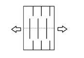
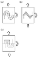
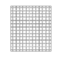
- the self-adhesive sheet is processed into one or more shapes selected from parallel lines, wavy, lattice, mesh, honeycomb, and dot shapes in the in-plane direction, [1] to [1] to [ 6] The self-adhesive sheet according to any one.
- a fixing member including a laminated portion in which the plurality of self-adhesive sheets according to any one of [1] to [7] are in contact with each other.
- a hook-and-loop fastener having the self-adhesive sheet according to any one of [1] to [8] as a removable surface.
- Self-adhesive sheet and Wiring and It is a wiring board equipped with The sheet is a wiring board containing a 4-methyl-1-pentene polymer and satisfying the following conditions.
- conditions For the self-adhesive sheet, the temperature showing the maximum value of the loss tangent (tan ⁇ ) obtained by dynamic viscoelasticity measurement under the conditions of a temperature rise rate of 4 ° C./min, a frequency of 1.59 Hz, and a strain amount of 0.1% is 10.
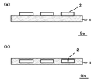
- the wiring is electrically connected to the electrodes and The wiring board according to [10], wherein the self-adhesive sheet has an opening for covering the wiring and exposing the electrodes.
- the wiring board according to any one of [10] to [13], wherein the wiring is formed of conductive ink.
- a self-adhesive member consisting of a self-adhesive sheet that has a self-adhesive surface and meets the following requirement 1.
- An opening / closing portion is formed by facing the self-adhesive surfaces.
- the opening / closing portion is a sealing member that opens when the self-adhesive surfaces facing each other are separated from each other and closes when the self-adhesive surfaces facing each other adhere to each other.
- the temperature at which the maximum value of the loss tangent (tan ⁇ ) obtained by dynamic viscoelasticity measurement under the conditions of a heating rate of 4 ° C./min, a frequency of 1.59 Hz, and a strain amount of 0.1% is at least 10 ° C.
- the 4-methyl-1-pentene polymer contains a structural unit derived from 4-methyl-1-pentene and a structural unit derived from an ⁇ -olefin having 2 to 20 carbon atoms other than 4-methyl-1-pentene.
- the self-adhesive member includes a resin plate arranged on the side opposite to the self-adhesive surface. The sealing member according to [19] or [20], wherein the resin plate satisfies the following requirements 2 to 4.
- the resin plate has a flexural modulus of 500 MPa to 2500 MPa (JIS7171).
- the resin plate has a thickness of 500 ⁇ m to 3000 ⁇ m.
- the resin plate is provided with hinge structures at both ends.
- a packaging member comprising the sealing member according to any one of [19] to [23] and a packaging material.
- the first invention it is possible to provide a self-adhesive sheet, a fixing member and a hook-and-loop fastener having improved fixing property.
- the second invention it is possible to provide a wiring board having good adhesion and an electronic component.
- the third invention it is possible to provide a sealing member having excellent airtightness of the opening / closing portion in an environment close to room temperature.
- the term “abbreviation” means to include a range in consideration of manufacturing tolerances, assembly variations, etc., unless otherwise specified explicitly.
- the notation “a to b” in the description of the numerical range means a or more and b or less unless otherwise specified.
- “1 to 5% by mass” means “1% by mass or more and 5% by mass or less”.
- the term “sheet” is a concept including not only what is generally called “sheet” but also what is generally called “film”. The thickness of what is generally called a “sheet” is 250 ⁇ m or more, and the thickness of what is generally called a “film” is less than 250 ⁇ m.
- self-adhesiveness means 0.026 MPa using a heat sealer (TP701B manufactured by Tester Sangyo Co., Ltd.) in which the surfaces of the sheets containing the 4-methyl-1-pentene polymer are set at 40 ° C.
- the maximum shear stress (MPa) in the tensile test (distance between chucks 50 mm, tensile speed 50 mm / min) after applying pressure for 1 second and leaving it in an environment of temperature 23 ° C. and relative humidity 50% for 24 hours is 2. It is intended to be at least 0.0 MPa.
- the self-adhesive sheet according to the present embodiment has a maximum value of loss tangent (tan ⁇ ) obtained by dynamic viscoelasticity measurement under the conditions of a temperature rise rate of 4 ° C./min, a frequency of 1.59 Hz, and a strain amount of 0.1%. There is at least one temperature in the range of 10 ° C. or higher and 100 ° C. or lower, and the maximum value of the loss tangent is 0.5 or more and 3.5 or less.
- a self-adhesive sheet is cut into a test piece having a length of 50 mm and a width of 5 mm, and has a frequency of 1.59 Hz, a heating rate of 4 ° C./min, a measurement temperature range of 0 ° C. to 110 ° C., a strain amount of 0.1%, and a distance between chucks of 20 mm.
- the present inventors have diligently studied in order to realize a self-adhesive sheet having excellent fixability.
- the temperature range showing the maximum value of the loss tangent (tan ⁇ ) and the maximum value of the loss tangent are adjusted to the above ranges to improve the fixability.
- the performance balance between flexibility and shape followability can be improved.
- the self-adhesive sheet in which the maximum value of the loss tangent is within the above range in the range of 10 ° C. or higher and 100 ° C. or lower can convert most of the mechanical energy given at the time of deformation into thermal energy and can absorb a large amount of energy. Therefore, it is considered that the restoration speed after deformation becomes slow. As a result, it is considered that the self-adhesive sheet can be well followed with the deformation while maintaining the flexibility, and as a result, the fixing property can be improved.
- the loss tangent of the self-adhesive sheet according to the present embodiment is, for example, (1) the type and blending ratio of the 4-methyl-1-pentene polymer (a1) described later, (2) the presence or absence of cross-linking of the sheet, and (2). 3) It is possible to control within the above range by appropriately adjusting the self-adhesive sheet molding method and the like. Specifically, for example, the mixing ratio of the 4-methyl-1-pentene polymer (a1) in the self-adhesive sheet may be increased, and the sheet may not be crosslinked.
- the self-adhesive sheet according to the present embodiment is preferably uncrosslinked from the viewpoint of improving the fixing property. That is, the self-adhesive sheet according to the present embodiment is preferably an uncrosslinked sheet that has not been subjected to a cross-linking treatment such as ionization radiation cross-linking using an electron beam or ⁇ -ray, for example.
- a cross-linking treatment such as ionization radiation cross-linking using an electron beam or ⁇ -ray, for example.
- the temperature showing the maximum value of the loss tangent (tan ⁇ ) of dynamic viscoelasticity is preferably at least one in the range of at least 10 ° C. or higher and 80 ° C. or lower, and is preferably 10 ° C. or higher and 60 ° C. It is more preferably one or more in the following range, further preferably one or more in the range of 10 ° C. or higher and 50 ° C. or lower, and particularly preferably one in the range of 10 ° C. or higher and 50 ° C. or lower.
- better adhesiveness can be obtained when the self-adhesive sheet comes into contact with human skin at about 25 ° C. to 40 ° C. or when the self-adhesive sheet is arranged at a position close to the human body.
- the maximum value of the loss tangent is preferably 0.8 or more, more preferably 1.0 or more, and further preferably 1.2 or more. ..
- the maximum value of the loss tangent is preferably 3.0 or less, and more preferably 2.8 or less.
- the larger the maximum value of the loss tangent the stronger the viscous property of the self-adhesive sheet.
- a self-adhesive sheet with strong viscous properties can convert more of the mechanical energy given when deforming into thermal energy and can absorb more energy, so it is thought that the restoration speed after deformation will be even slower. Be done. As a result, while maintaining the flexibility of the self-adhesive sheet, the shape after deformation can be maintained even better, and the deformation can follow the shape even better, and as a result, the fixing property in the surface direction can be improved. Conceivable.
- the self-adhesive sheet according to the present embodiment has an arithmetic average roughness Ra of one surface in the range of 0.01 to 10 ⁇ m and a ten-point average roughness Rz of 0.1 to 50 ⁇ m. As a result, good fixing property can be obtained.
- the arithmetic mean roughness Ra is preferably 0.02 to 8 ⁇ m, more preferably 0.03 to 5 ⁇ m. Further, the arithmetic mean roughness Ra is preferably 3.5 ⁇ m or less, more preferably 2 from the viewpoint of obtaining good adhesiveness by entwining fine irregularities on the surface of the self-adhesive sheet at the operating temperature of the self-adhesive sheet.
- the ten-point average roughness Rz is preferably 0.2 to 40 ⁇ m, more preferably 0.3 to 25 ⁇ m, and even more preferably 0.3 to 20 ⁇ m.
- the variation in unevenness can be effectively suppressed, and a more uniform fixing force can be obtained on the entire surface of the self-adhesive sheet.
- At least the arithmetic average roughness Ra and the ten-point average roughness Rz of the surface on the side to be the adhesive surface (fixed surface) may satisfy the above numerical range. ..
- the arithmetic average roughness Ra and the ten-point average roughness Rz satisfy the above numerical range at least on the surface side where the self-adhesive sheets oppose each other.
- the method for adjusting the surface roughness of the self-adhesive sheet according to the present embodiment is not particularly limited, and a known method can be used. For example, a method by molding such as embossing in the sheet manufacturing process or winding the sheet. At the time of removal, a method of sandwiching a sheet (separator) between the sheets to transfer the surface shape of the sheet, polishing, and blasting such as water blasting and air blasting may be performed. Of these, the water blast treatment is preferable as the blast treatment.
- the arithmetic average roughness Ra and the ten-point average roughness Rz can be measured in accordance with JIS B0610-2001.
- the thickness of the self-adhesive sheet according to the present embodiment is not particularly limited, but is preferably in the range of 0.01 mm or more and 30 mm or less, more preferably in the range of 0.01 mm or more and 10 mm or less, and further preferably 0.02 mm or more. The range is 5 mm or less, and more preferably 0.03 mm or more and 2 mm or less.
- the self-adhesive sheet according to the present embodiment may have ventilation holes in order to enhance breathability, depending on the intended use.
- ventilation holes in order to enhance breathability, depending on the intended use.
- a large number of vents communicating with each other can be provided on the front and back by processing techniques such as mechanical punching, needle processing, laser perforation, and water jet.
- the density of the self-adhesive sheet according to the present embodiment measured according to ASTM D 1505 (underwater substitution method) is preferably 0.3 to 1.5 g / cm 3 , more preferably 0.5 to 1.2 g / cm 3. , More preferably 0.8 to 0.9 g / cm 3 , and even more preferably 0.83 to 0.85 g / cm 3 .
- the self-adhesive sheet of the present embodiment When the self-adhesive sheet of the present embodiment is applied to an application utilizing transparency described later, it is desirable that the internal haze with respect to visible light (hereinafter, also simply referred to as “internal haze”) is 30% or less.
- the "internal haze” refers to a haze excluding the haze due to the shape of the outer surface of the self-adhesive sheet.
- the “internal haze” is a value measured at 25 ° C. for the self-adhesive sheet in accordance with JIS-K7105.
- the internal haze of the self-adhesive sheet of the present embodiment is preferably 30% or less, more preferably 20% or less, further preferably 13% or less, still more preferably 5% or less. , 2.0% or less is even more preferable, and 1.0% or less is particularly preferable.
- the lower the internal haze of the self-adhesive sheet of the present embodiment is, the better from the viewpoint of transparency, but from the viewpoint of balance with adhesiveness and the like, the lower limit is 0.01% or more. Is preferable. That is, the transparency of the self-adhesive sheet of the present embodiment can be evaluated by the internal haze.
- the transparency of the self-adhesive sheet of the present embodiment may be evaluated not only by the above-mentioned internal haze but also by the internal light transmittance.
- the "internal light transmittance” refers to the light transmittance excluding the influence of the shape of the outer surface of the self-adhesive sheet.
- the internal light transmittance of the self-adhesive sheet of the present embodiment is preferably 90.0% or more, more preferably 95.0% or more, further preferably 97.0% or more, still more preferably 98.0% or more. 99.0% or more is even more preferable, ideally 100%.
- the internal haze and internal light transmittance of the self-adhesive sheet of the present embodiment can be measured as follows.
- Haze (H2) and haze (H3) are measured using the following devices under the following measurement conditions.
- the light transmittance (T2) (%) is measured instead of the haze (H2) in the measurement of the haze (H2), and the haze is measured in the measurement of the haze (H3).
- the light transmittance (T3) (%) is measured instead of (H3).
- the internal light transmittance (T1) (%) of the self-adhesive sheet is obtained by the following formula (2).
- Internal light transmittance (T1) 100- (light transmittance (T2) -light transmittance (T3)) (2)
- the self-adhesive sheet according to this embodiment contains a 4-methyl-1-pentene polymer (a1).
- the maximum value of the loss tangent (tan ⁇ ) can be made larger.
- the 4-methyl-1-pentene polymer (a1) according to the present embodiment include a structural unit (c1) derived from 4-methyl-1-pentene and a carbon atom other than 4-methyl-1-pentene.
- Examples thereof include a 4-methyl-1-pentene / ⁇ -olefin copolymer (c) containing a structural unit (c2) derived from ⁇ -olefins of numbers 2 to 20.
- ⁇ -olefin having 2 to 20 carbon atoms does not contain 4-methyl-1-pentene unless otherwise specified.
- the 4-methyl-1-pentene / ⁇ -olefin copolymer (c) according to the present embodiment has a structural unit (c1) and a structural unit (c2) from the viewpoint of further improving the flexibility and fixability of the self-adhesive sheet. ),
- the content of the constituent unit (c1) is 10 mol% or more and 90 mol% or less
- the content of the constituent unit (c2) is 10 mol% or more and 90 mol% or less. It is preferable to have.
- the 4-methyl-1-pentene / ⁇ -olefin copolymer (c) according to the present embodiment is a structural unit (c1) from the viewpoint of improving the flexibility and mechanical properties of the self-adhesive sheet.
- the content of the constituent unit (c1) is 30 mol% or more and 90 mol% or less, and the content of the constituent unit (c2) is 10 mol% or more. It is more preferably 70 mol% or less, the content of the constituent unit (c1) is 50 mol% or more and 90 mol% or less, and the content of the constituent unit (c2) is 10 mol% or more and 50 mol% or less. It is even more preferable that the content of the structural unit (c1) is 60 mol% or more and 90 mol% or less, and the content of the structural unit (c2) is 10 mol% or more and 40 mol% or less. It is particularly preferable that the content of the structural unit (c1) is 65 mol% or more and 90 mol% or less, and the content of the structural unit (c2) is 10 mol% or more and 35 mol% or less.
- the ⁇ -olefin having 2 to 20 carbon atoms used in the 4-methyl-1-pentene / ⁇ -olefin copolymer (c) is, for example, a linear or branched ⁇ -olefin.
- Cyclic olefins, aromatic vinyl compounds, conjugated dienes, functionalized vinyl compounds and the like, and linear ⁇ -olefins are preferable.
- the number of carbon atoms of the linear ⁇ -olefin is preferably 2 to 10, more preferably 2 to 5, and even more preferably 2 to 3.
- Examples of the linear ⁇ -olefin include ethylene, propylene, 1-butene, 1-pentene and the like, and ethylene, propylene, 1-butene, 1-pentene, 1-hexene, 1-octene and 1-decene.
- One or more selected from, and at least one selected from ethylene and propylene are more preferred.
- the number of carbon atoms of the branched ⁇ -olefin is preferably 5 to 20, more preferably 5 to 15.
- Examples of the branched ⁇ -olefin include 3-methyl-1-butene, 3-methyl-1-pentene, 3-ethyl-1-pentene and the like.
- the number of carbon atoms of the cyclic olefin is preferably 5 to 15.
- Examples of the cyclic olefin include cyclopentene, cyclohexene, cycloheptene, norbornene, 5-methyl-2-norbornene, tetracyclododecene, vinylcyclohexane and the like.
- aromatic vinyl compound examples include styrene, ⁇ -methylstyrene, o-methylstyrene, m-methylstyrene, p-methylstyrene, o, p-dimethylstyrene, o-ethylstyrene, m-ethylstyrene, and p-.
- aromatic vinyl compound examples include mono such as ethyl styrene or polyalkyl styrene.
- the number of carbon atoms of the conjugated diene is preferably 4 to 20, more preferably 4 to 10.
- conjugated diene examples include 1,3-butadiene, isoprene, chloroprene, 1,3-pentadiene, 2,3-dimethylbutadiene, 4-methyl-1,3-pentadiene, 1,3-hexadiene, and 1,3-.
- Octadien and the like can be mentioned.
- Examples of the functionalized vinyl compound include hydroxyl group-containing olefins, halogenated olefins, (meth) acrylic acids, propionic acids, 3-butenoic acids, 4-pentenoic acids, 5-hexenoic acids, 6-heptenoic acids, and 7-octenes.
- Unsaturated carboxylic acids such as acids, 8-nonenoic acid, 9-decenoic acid, 10-undecenoic acid and their acid anhydrides and unsaturated amines such as acid halides, allylamines, 5-hexeneamines and 6-hepteneamines, (2, 7-Octadienyl) succinic acid anhydride, pentapropenyl succinic acid anhydride, unsaturated epoxy compound, ethylenically unsaturated silane compound and the like can be mentioned.
- the hydroxyl group-containing olefin include linear or branched terminal hydroxylated ⁇ -olefins having 2 to 20 carbon atoms, preferably 2 to 15 carbon atoms.
- the halogenated olefin include linear or branched halogenated ⁇ -olefins having 2 to 20 carbon atoms, preferably 2 to 15 carbon atoms.
- ⁇ -olefins having 2 to 20 carbon atoms can be used alone or in combination of two or more.
- ⁇ -olefins having 2 to 5 carbon atoms are preferable, and ethylene and propylene are more preferable, but propylene is particularly preferable in that flexibility and the like can be improved.
- the 4-methyl-1-pentene / ⁇ -olefin copolymer (c) contains a structural unit (c1) and a structural unit other than the structural unit (c2) as long as the object of the present invention is not impaired. May be good.
- Other configurations include structural units derived from non-conjugated polyenes. Examples of the non-conjugated polyene include linear, branched or cyclic diene having a carbon atom number of preferably 5 to 20, more preferably 5 to 10, various norbornene, norbornadiene and the like. Among these, 5-vinylidene-2-norbornene and 5-ethylidene-2-norbornene are preferable.
- the ultimate viscosity [ ⁇ ] of the 4-methyl-1-pentene polymer according to the present embodiment in decalin at 135 ° C. is 0. It is preferably 01 to 5.0 dL / g, more preferably 0.1 to 4.0 dL / g, further preferably 0.5 to 3.0 dL / g, and 1.0 to 2 It is particularly preferably .8 dL / g.
- the density of the 4-methyl-1-pentene polymer according to the present embodiment measured according to ASTM D 1505 (substitution method in water) is preferably 0.810 to 0.850 g / cm 3 , more preferably 0.820. It is ⁇ 0.850 g / cm 3 , more preferably 0.830 to 0.850 g / cm 3 .
- the 4-methyl-1-pentene polymer according to this embodiment can be produced by various methods.
- the content of the 4-methyl-1-pentene polymer (a1) in the self-adhesive sheet according to the present embodiment is not particularly limited, but is preferably 50% by mass when the entire self-adhesive sheet is 100% by mass.
- the above is more preferably 60% by mass or more, still more preferably 65% by mass or more, still more preferably 70% by mass or more, particularly preferably 75% by mass or more, while preferably 100% by mass or less, more preferably 99% by mass or more. It is 5.5% by mass or less, more preferably 99% by mass or less, still more preferably 98% by mass or less, and particularly preferably 97% by mass or less.
- the self-adhesive sheet according to the present embodiment may contain components other than the above-mentioned 4-methyl-1-pentene polymer (a1).
- the self-adhesive sheet according to the present embodiment is a sex-modified resin (a2) (however, a 4-methyl-1-pentene polymer according to the present embodiment (however, from the viewpoint of improving the appearance, touch, and fixability). It may contain) except a1).
- the modified resin (a2) according to the present embodiment include one or more selected from thermoplastic resins, thermoplastic elastomers and rubbers.
- thermoplastic resin examples include low-density polyethylene, medium-density polyethylene, high-density polyethylene, and high-pressure method low-density.
- polyethylene Polyethylene, polypropylene, poly1-butene, poly4-methyl-1-pentene, poly3-methyl-1-butene, ethylene / ⁇ -olefin copolymer, propylene / ⁇ -olefin copolymer, 1-butene / ⁇ -Thermoplastic polyolefin resins such as olefin copolymers, cyclic olefin copolymers, and chlorinated polyolefins; aliphatic polyamides (nylon 6, nylon 11, nylon 12, nylon 66, nylon 610, nylon 612), polyether blockamides Thermoplastic polyamide resin such as polymer; thermoplastic polyester resin such as polyethylene terephthalate and polybutylene terephthalate; thermoplastic vinyl aromatic resin such as polystyrene, ABS resin and AS resin; vinyl chloride resin; vinylidene chloride resin; acrylic Resin; ethylene / vinyl acetate copolymer; ethylene / methacryl
- examples of the rubber include ethylene / ⁇ -olefin / diene copolymer rubber, propylene / ⁇ -olefin / diene copolymer rubber and the like.
- examples of the thermoplastic elastomer include olefin-based elastomers, styrene-based elastomers, acid-modified styrene-based elastomers, vinyl chloride-based elastomers, urethane-based elastomers, ester-based elastomers, and amide-based elastomers.
- these modified resins (a2) may be acid-modified with acrylic acid, methacrylic acid, maleic acid or the like. These modified resins (a2) may be used alone or in combination of two or more.
- low density polyethylene low density polyethylene, medium density polyethylene, high density polyethylene, high pressure method low density polyethylene, polypropylene, poly 1-butene, poly 4-methyl-1-pentene, poly 3-methyl- One or more selected from 1-butene, ethylene / ⁇ -olefin copolymer, propylene / ⁇ -olefin copolymer, 1-butene / ⁇ -olefin copolymer is preferable, and polyethylene, polypropylene, poly 1 -Buten, poly 4-methyl-1-pentene, ethylene / ⁇ -olefin copolymer, propylene / ⁇ -olefin copolymer, 1-butene / ⁇ -olefin copolymer, ethylene / vinyl acetate copolymer, poly One or more selected from ether blockamide, ionomer, fluorine-based resin, acid-modified fluorine-based resin, rosin-based resin, terpen
- the 4-methyl-1-pentene polymer (a1) has appropriate compatibility.
- vinyl SIS product name: Hybler, brand 5127) manufactured by Kuraray
- vinyl SEPS product name: Hybler, brand 7125
- SEBS SEBS manufactured by Asahi Kasei Co., Ltd.
- S.O. E, Brand S1605, S1611, and L609
- the self-adhesive sheet according to the present embodiment may be used alone from these modified resins (a2), or may be used in combination of two or more.
- the content of the modified resin (a2) in the self-adhesive sheet according to the present embodiment is not particularly limited, but when the total amount of the self-adhesive sheet is 100% by mass, it is preferably 0.5% by mass or more, more preferably 0.5% by mass or more. 1% by mass or more, still more preferably 2% by mass or more, still more preferably 3% by mass or more, preferably 50% by mass or less, more preferably 40% by mass or less, still more preferably 35% by mass or less, still more preferably. Is 30% by mass or less, particularly preferably 25% by mass or less.
- the content of the modified resin (a2) is at least the above lower limit value, the appearance, touch, fixability, etc.
- the performance balance such as fixability and flexibility of the self-adhesive sheet according to the present embodiment can be further improved.
- the self-adhesive sheet according to the present embodiment is, if necessary, a heat-resistant stabilizer, an antioxidant, an ultraviolet absorber, a pigment, an antioxidant, a copper damage inhibitor, a flame retardant, a neutralizing agent, a plasticizer, and a nucleation.
- Additives such as agents, weather stabilizers, light stabilizers, antioxidants, fatty acid metal salts, softeners, dispersants, colorants, lubricants, natural oils, synthetic oils and waxes may be added.
- the plasticizer, the softener, the natural oil, and the synthetic oil adjust the temperature at which the maximum value of the loss positive contact (tan ⁇ ) of the solid viscoelasticity of the self-adhesive sheet according to the present embodiment is shown and the maximum value of the loss positive contact. Therefore, the type and the amount of addition may be controlled and used.
- each component is dry-blended, a tumbler mixer, a Banbury mixer, a single-screw extruder, a twin-screw extruder, a high-speed twin-screw extruder, and a thermal roll. It can be prepared by mixing or melting and kneading with the like.
- the self-adhesive sheet according to the present embodiment may be a single layer or a multi-layer.
- at least one layer may be a layer containing a 4-methyl-1-pentene polymer (a1), and two or more layers may contain a 4-methyl-1-pentene polymer (a1). good.
- a resin composition containing a 4-methyl-1-pentene polymer (a1) or a 4-methyl-1-pentene polymer (a1) is molded into a sheet.
- the molding apparatus and molding conditions are not particularly limited, and conventionally known molding apparatus and molding conditions can be adopted, and for example, known methods such as extrusion molding, inflation molding, and calendar ring molding can be applied. Above all, it is preferable to mold by an extrusion molding apparatus. Further, even when the self-adhesive sheet has a multi-layer structure, known methods such as coextrusion (extrusion using a multi-die) and various laminating methods can be appropriately applied.
- the fixing member according to the present embodiment includes a laminated portion in which the plurality of self-adhesive sheets are laminated so as to be in direct contact with each other so as to face each other. Since the self-adhesive sheet is excellent in the fixing property in the surface direction, the adhesion between layers is good, and the delamination of the laminated portion is highly suppressed.
- the laminated portion may be a product in which two self-adhesive sheets are laminated, a product in which three or more layers are laminated, or a long self-adhesive sheet may be folded and stacked.
- a composite may be formed in which other members different from the above-mentioned self-adhesive sheet are laminated on the laminated portion.
- the self-adhesive sheet described above has an excellent balance of fixing property, flexibility, and shape-following property, and thus has excellent adhesiveness to other members. Therefore, even if the self-adhesive sheet is used for a long period of time, the adhesiveness between the self-adhesive sheet and other members can be maintained, and the durability can be excellent. That is, the complex according to the present embodiment has an excellent balance of flexibility, shape memory, stress relaxation, and durability.
- a composite can be produced by laminating other members on the above self-adhesive sheet and, if necessary, heat-pressing or welding with a press or the like. Further, a composite can also be produced by applying an adhesive between the self-adhesive sheet and the other member, and then joining the self-adhesive sheet and the other member via the adhesive.
- an SBR-based solvent adhesive or a hot melt adhesive composed of EVA, petroleum resin, or a mixture of EVA and petroleum resin can be preferably used.
- the other members are not particularly limited, but for example, woven fabric, non-woven fabric, synthetic fiber, artificial leather, synthetic leather, natural leather, fur, metal, carbon material, rubber, thermoplastic elastomer, thermoplastic resin, thermosetting resin, etc.
- examples thereof include polymer foam, mesh structure (warp knitted fiber, double Russell mesh, three-dimensional spring structure, etc.), fiber reinforced plastic, paper, wood, glass, stone, ceramic and the like.
- the hook-and-loop fastener according to the present embodiment has the above-mentioned self-adhesive sheet as a removable surface. Since the self-adhesive sheet is excellent in fixing property in the surface direction, good adhesiveness can be obtained by using the self-adhesive sheet as the attachment / detachment surface of the hook-and-loop fastener, and the self-adhesive sheet can be repeatedly attached and detached. Further, unlike the conventional surface fastener having a loop, the surface fastener according to the present embodiment does not break the loop due to repeated attachment / detachment, so that the decrease in adhesiveness can be relatively reduced. Further, since the hook-and-loop fastener according to the present embodiment does not make a noise when it is removed, it is expected to be applied in a wider range of fields than the conventional hook-and-loop fastener.
- the hook-and-loop fastener according to the present embodiment can be widely applied to applications that are repeatedly attached and detached.
- various industries such as clothing, medical / nursing care products, housing equipment, automobiles / aircraft, etc. It can be used in the field.
- the above-mentioned self-adhesive sheet easily fits the shape of the body and easily obtains adhesiveness, it is used as a fixing member for clothing, for example, for innerwear, sports, outdoor clothing, and the like. be able to.
- a fixing member for shoes it can be used for sneakers, pumps, sandals and the like.
- a fixing member for fashion accessories.
- a medical fixing member for example, it can be used for a fixing tape, a band, a belt, a supporter, or the like.
- materials for wearables for example, base materials such as biological sensing devices, e-sports devices, techno-sports devices, VR (virtual reality) and AR (augmented reality), smart watches, smart glasses, robot suits, etc. It can be used for members and the like.
- the above self-adhesive sheet can obtain more flexibility and followability at a temperature close to body temperature, it is possible to improvise daily necessities such as bags, cups, and boxes from the viewpoint of easy adhesion at body temperature. Can be done. Taking advantage of this ease, it can be used, for example, for outdoor goods, sports-related goods, base materials and members in the event of a disaster or emergency. From the same point of view, it can be used as a new material for art, art, work, etc. such as DIY material, art work material, origami substitute material.
- the above self-adhesive sheet has a high affinity with the human body, it is also suitable for apparel materials, sheet materials, bedding materials, grips, eyeglasses, helmets, wigs, headphones, earphones, watches, belts and the like. It can be used. In addition, it can be used for a wide range of purposes such as toys, stationery, cable ties, wraps, and daily necessities such as seal materials.
- the self-adhesive sheet according to the present embodiment has high transparency, the range of application will be further expanded. For example, if it is used for wristwatch bands, inner fasteners and hooks for dresses, brassieres, etc., it can add new design and design that makes use of transparency, expanding the possibilities of various products. be able to.
- the transparency of the self-adhesive sheet according to the present embodiment in this case is as described above.
- the wiring board 9 of the present embodiment includes a self-adhesive sheet 1 and a wiring 2, and the self-adhesive sheet 1 contains a 4-methyl-1-pentene polymer. Moreover, the following conditions are satisfied.
- the temperature showing the maximum value of the loss tangent (tan ⁇ ) obtained by dynamic viscoelasticity measurement under the conditions of a temperature rise rate of 4 ° C./min, a frequency of 1.59 Hz, and a strain amount of 0.1% is There is one or more in the range of 10 ° C. or higher and 100 ° C. or lower, and the maximum value of the loss tangent is 0.5 or more and 3.5 or less.
- FIG. 1A shows a wiring board 9a in which a plurality of wirings 2 are arranged on the self-adhesive sheet 1
- FIG. 1B shows the inside of the self-adhesive sheet 1.
- a wiring board 9b in which a plurality of wirings 2 are embedded is shown in the above.
- the number and arrangement method of the wiring 2 is not particularly limited, and a known technique can be adopted.
- a part of the wiring may be arranged so as to be flush with a part of the surface of the sheet, and the sheet has a recess and is arranged so that at least a part of the wiring is exposed in the recess. You may.
- the wiring 2 may be a member having conductivity, and includes a so-called conductive layer and an electrode 4 described later. The details of the self-adhesive sheet 1, the wiring 2, and the electrode 4 will be described later.
- the wiring board 9 of the present embodiment can obtain good adhesion to a living body and is effectively applied as a wearable device. That is, by controlling the predetermined loss tangent of the 4-methyl-1-pentene polymer contained in the self-adhesive sheet 1 as an index, at the environmental temperature at which the electronic device using the wiring board 9 is used. As a result of obtaining good viscosity, it is possible to follow the living body well and exhibit excellent adhesion.
- the adhesion to the living body means that the self-adhesive sheet 1 adheres to or is fixed to the shape and movement of the outer surface of the living body due to the flexibility and shape followability of the self-adhesive sheet 1.
- the adhesion obtained by this is intended.
- the self-adhesive sheet 1 has a loss tangent (tan ⁇ ) obtained by dynamic viscoelasticity measurement under the conditions of a temperature rise rate of 4 ° C./min, a frequency of 1.59 Hz, and a strain amount of 0.1%.
- the maximum value is at least one in the range of 10 ° C. or higher and 100 ° C. or lower, and the maximum value of the loss tangent is 0.5 or more and 3.5 or less.
- the self-adhesive sheet 1 is cut into a test piece having a length of 50 mm and a width of 5 mm, and has a frequency of 1.59 Hz, a heating rate of 4 ° C./min, a measurement temperature range of 0 ° C. to 110 ° C., a strain amount of 0.1%, and between chucks. It can be measured using a rheometer under the conditions of a distance of 20 mm and a tension mode.
- the present inventor has diligently studied in order to realize a self-adhesive sheet 1 having excellent adhesion and fixing property.
- the temperature range showing the maximum value of the loss tangent (tan ⁇ ) and the maximum value of the loss tangent are adjusted to the above ranges. It was found that the performance balance of adhesion / fixation, flexibility and shape followability can be improved.
- the loss tangent (tan ⁇ ) in the relatively low frequency region of 1.59 Hz
- the force also called slow force
- the self-adhesive sheet 1 in which the maximum value of the loss tangent is within the above range in the range of 10 ° C. or higher and 100 ° C. or lower can convert most of the mechanical energy given when deforming into thermal energy, and increases the energy.
- the restoration speed after deformation becomes slow.
- the self-adhesive sheet 1 can be well followed with the deformation while maintaining the flexibility, and as a result, the fixing property can be improved.
- the loss tangent of the self-adhesive sheet 1 according to the present embodiment is, for example, (1) the type and blending ratio of the 4-methyl-1-pentene polymer (a1) described later, and (2) the presence or absence of cross-linking of the sheet. , (3) Self-adhesive sheet 1 It is possible to control within the above range by appropriately adjusting the molding method and the like. Specifically, for example, the compounding ratio of the 4-methyl-1-pentene polymer (a1) in the self-adhesive sheet 1 is increased, the sheet is not crosslinked, and the like.
- the self-adhesive sheet 1 according to the present embodiment is preferably uncrosslinked from the viewpoint of improving fixability and adhesion. That is, the self-adhesive sheet 1 according to the present embodiment is preferably an uncrosslinked sheet that has not been subjected to a cross-linking treatment such as ionization radiation cross-linking using an electron beam or ⁇ -ray, for example.
- a cross-linking treatment such as ionization radiation cross-linking using an electron beam or ⁇ -ray, for example.
- the temperature showing the maximum value of the loss tangent (tan ⁇ ) of dynamic viscoelasticity is preferably at least one in the range of at least 10 ° C. or higher and 80 ° C. or lower, and is 10 ° C. or higher. It is more preferably one or more in the range of 60 ° C. or lower, further preferably one or more in the range of 10 ° C. or higher and 50 ° C. or lower, and particularly preferably one in the range of 10 ° C. or higher and 50 ° C. or lower.
- shape followability can be obtained.
- the maximum value of the loss tangent is preferably 0.8 or more, more preferably 1.0 or more, and preferably 1.2 or more. More preferred.
- the maximum value of the loss tangent is preferably 3.0 or less, and more preferably 2.8 or less.
- the larger the maximum value of the loss tangent the stronger the viscous property of the self-adhesive sheet 1.
- the self-adhesive sheet 1 having a strong viscous property can convert more of the mechanical energy given when deforming into thermal energy and can absorb more energy, so that the restoration speed after deformation becomes even slower. It is considered to be.
- the shape after deformation can be maintained even better, and the deformation can follow the shape even better.
- the body can be fixed to the skin and movement of the living body. It is thought that the property and adhesion can be improved.
- the wiring board 10 of the present embodiment includes a wiring 2 electrically connected to the electrode 4, a self-adhesive sheet 1 having an opening for covering the wiring 2 and exposing the electrode 4. May be provided. That is, the wiring board 10 is an example in which the base material 3, the wiring 2, and the self-adhesive sheet 1 are laminated in this order, and the electrode 4 is exposed on a part of the outer surface of the self-adhesive sheet 1. be.
- the electronic device 11 of the present embodiment includes a wiring board 10, an electrode 4 exposed in the opening of the self-adhesive sheet 1, and an electronic component electrically connected to the wiring 2. Note that the electronic components are not shown in FIG.
- the self-adhesive sheet 1 of the present embodiment has flexibility and shape-following property, and functions to make the wiring board 10 adhere well to the living body.
- the self-adhesive sheet 1 has an opening that covers the wiring 2 and exposes the electrode 4.
- the self-adhesive sheet 1 is preferably coated so as to suppress electric leakage and discharge from the wiring 2.
- the coating is not limited to the case of being continuous, and there may be a part of which is discontinuous.
- the number, arrangement, size, etc. of the openings of the self-adhesive sheet 1 are set according to the number, arrangement, size, etc. of the electrodes 4 used. From the viewpoint of suppressing electric leakage and discharge, it is sufficient that at least a part of the electrode 4 is exposed in the opening, and the opening area is preferably the same as or smaller than the cross-sectional area of the electrode 4.
- the self-adhesive sheet 1 preferably has at least an insulating surface on the outer surface side.
- the self-adhesive sheet 1 of the wiring board 10 is directly attached to the skin of a living body to prevent electrical stimulation when energized, and can be used safely.
- the self-adhesive sheet 1 may have at least a part of air permeability depending on the application. As a result, it is possible to improve the feel of the electronic device 11 using the wiring board 10 and reduce the occurrence of stuffiness. In addition, the weight can be reduced and the fit can be improved.
- the air permeability means that the air permeability is 1 cc / cm 2 / sec or more as measured under the conditions of 24 ° C. and 50% RH in accordance with JIS K6400-7: 2012 (Method B). preferably, more preferably 5cc / cm 2 / sec or more, more preferably 10cc / cm 2 / sec or more, still more preferably at 20cc / cm 2 / sec or more, 30 cc / cm 2 / It is particularly preferable that it is sec or more.
- the upper limit of the air volume is not particularly limited, but is, for example, 10000 cc / cm 2 / sec or less.
- the breathability of the self-adhesive sheet 1 is, for example, (1) the self-adhesive sheet 1 is made into a foam, (2) the self-adhesive sheet 1 is provided with a through hole, or (3) the self-adhesive sheet 1 is provided with a through hole. Examples thereof include those obtained by deforming the shape, and the above (1) to (3) may be combined. Each will be described below.
- the self-adhesive sheet 1 of the above (1) is used as a foam
- open cells contained in the foam may be connected from one surface to the other surface of the self-adhesive sheet 1 to obtain air permeability. ..
- the self-adhesive sheet 1 may have closed cells in addition to open cells. Details of the foam will be described later.
- the through hole of (2) above can be obtained by a known drilling process on the molded self-adhesive sheet 1.
- a drilling process for example, mechanical punching, needle processing, laser perforation, water jet and the like can be used.
- the hole diameter of the through hole is not particularly limited, and examples thereof include 0.1 mm and more and 50 mm or less.
- the through holes may be uniformly formed on the entire surface of the self-adhesive sheet 1, and may be formed only in a portion where breathability is desired to be obtained, or the density may be increased in a portion where breathability is desired to be obtained. It may be formed as follows.
- the shape of the self-adhesive sheet 1 can be deformed in a parallel line shape, a wavy shape, a grid shape, a mesh shape (mesh shape), a honeycomb shape, a dot shape, or the like in the in-plane direction (xy plane) of the self-adhesive sheet 1. It is possible to process a gap in the shape of. These shapes may be a combination of one or more shapes. Further, it is sufficient that at least a part of the self-adhesive sheet 1 is processed.
- FIG. 3 shows an example of the self-adhesive sheet 1 having parallel linear gaps.
- the self-adhesive sheet 1 can be extended in the direction orthogonal to the parallel lines.
- the wavy shape is not limited to a curved line, and a triangular or rectangular uneven shape may be periodically repeated like a wave.
- FIG. 4A shows an example of a self-adhesive sheet 1 having a curved wavy gap
- FIG. 4A shows an example of a self-adhesive sheet 1 having a curved wavy gap
- FIG. 4B shows an example of a self-adhesive sheet 1 having a triangular wavy gap
- FIG. 4 (C) shows an example of the self-adhesive sheet 1 having a rectangular wavy gap.
- the self-adhesive sheet 1 can be extended in the uneven direction of the wave (vertical direction in FIG. 3).
- FIG. 4 shows an example in which two wavy slits for one cycle are formed in parallel, but the wave cycle and the number of slits are not limited to this.
- FIG. 5 shows an example of a honeycomb-shaped self-adhesive sheet 1 in a plan view
- FIG. 6 shows an example of a mesh-shaped self-adhesive sheet 1 in a plan view
- FIG. 7 shows a grid pattern in a plan view. An example of the self-adhesive sheet 1 of the above is shown.
- the gap may be either a slit-shaped thin wire or a hole-shaped opening.
- the size of the gap is appropriately set according to the application and the processed shape, but from the viewpoint of obtaining good deformability while maintaining the mechanical strength, the gap size is appropriately set.
- a processing method it can be obtained by extruding the raw material to be the self-adhesive sheet 1 into a sheet shape by using a net extrusion molding method or the like.
- the resin composition is extruded from the nozzle of a rotary die for net forming provided at the tip of the extruder, welded into a net shape, and the obtained extrusion net is passed through a water tank at a predetermined temperature.
- a slit may be formed in the molded self-adhesive sheet 1 by a known method.
- the self-adhesive sheet 1 preferably has deformability.
- the self-adhesive sheet 1 is deformed into the shape of (3) above, the flexibility and elasticity of the self-adhesive sheet 1 can be further improved.
- the wiring 2 and the base material 3 may also be deformed into substantially the same shape.
- the wiring board 10 as a whole can have deformability such as flexibility and / or elasticity.
- the self-adhesive sheet 1 when a set of wavy slits for one cycle is formed in the substantially central portion of the self-adhesive sheet 1, the self-adhesive sheet 1 can be bent at the substantially central portion. Thereby, deformability such as bendability can be obtained.
- the wiring 2 is processed into a wavy shape in the in-plane direction of the self-adhesive sheet 1 and is arranged between a set of the above-mentioned wavy slits so that one of the wirings 2 is passed through the folding line of the self-adhesive sheet 1. Allows electrical transmission from one area to the other.
- the self-adhesive sheet 1 is wavy along the in-plane direction (z-axis direction, thickness direction). It may be (including folds and bellows).
- the wiring 2 and the base material 3 are also preferably wavy (including folds and bellows) along the in-plane direction (see FIG. 8).
- the self-adhesive sheet 1 of the present embodiment may be a foam depending on the application.
- the foam has single cells and / or open cells.
- the degree of air bubbles in the foam may be different in the thickness direction of the self-adhesive sheet 1 or may be uniform.
- the density of the foam may increase from the outer surface side of the self-adhesive sheet 1 toward the wiring 2 side.
- the density of the foam is relatively low on the outer surface side of the self-adhesive sheet 1, flexibility is obtained, and good adhesion is maintained, while the density of the foam is on the wiring 2 side of the self-adhesive sheet 1. Is relatively high, hardness is obtained, and it becomes easy to protect the wiring 2.
- the foam of the self-adhesive sheet 1 can be obtained by a known method.
- a resin composition as a raw material of the self-adhesive sheet 1 and a foaming agent are used in the method for producing the self-adhesive sheet 1 described later. It can be obtained by foam molding into a sheet shape with an extrusion molding machine.
- Examples of the foaming agent used when molding the self-adhesive sheet 1 according to the present embodiment include a chemical foaming agent and a physical foaming agent.
- Chemical foaming agents include sodium bicarbonate, ammonium bicarbonate, various carboxylates, sodium borohydride, azodicarbamide, N, N-dinitrosopentamethylenetetramine, P, P-oxybis (benzenesulfonyl hydrazide). , Azobisisobutyronitrile, paratoluenesulfonyl hydrazide, sodium borohydride and the like.
- the physical foaming agent examples include carbon dioxide, nitrogen, and a mixture of carbon dioxide and nitrogen, all of which can be supplied in a gaseous, liquid or supercritical state. It is preferable that the chemical foaming agent is uniformly mixed with the 4-methyl-1-pentene polymerization system resin composition which is the raw material of the self-adhesive sheet 1 before being put into the extrusion molding machine.
- carbon dioxide is used as the physical foaming agent
- the 4-methyl-1-pentene polymerization system resin composition is kneaded in the extruder to be in a plasticized state, and then directly injected into the extruder. It is preferable to do so.
- the foaming ratio of the self-adhesive sheet 1 is not particularly limited, and can be appropriately determined in consideration of various physical properties of the self-adhesive sheet 1.
- the self-adhesive sheet 1 of the present embodiment may have fine irregularities on the outer surface depending on the intended use.
- the adhesiveness (self-adhesiveness) between the self-adhesive sheets 1 can be dramatically improved.
- the wiring board 10 is more satisfactorily fixed to the living body by fixing the self-adhesive sheets 1 to each other (self-adhesive).
- a high adhesive force in the in-plane direction of the self-adhesive sheet 1 can be obtained.
- the outer surface of the self-adhesive sheet 1 is one surface of the wiring board 10 and is a surface on the living body side.
- the self-adhesive sheet 1 preferably has an outer surface arithmetic average roughness Ra in the range of 0.01 to 10 ⁇ m and / or a ten-point average roughness Rz of 0.1 to 50 ⁇ m. be.
- the arithmetic mean roughness Ra is more preferably 0.02 to 8 ⁇ m, still more preferably 0.03 to 5 ⁇ m.
- the ten-point average roughness Rz is more preferably 0.2 to 40 ⁇ m, and even more preferably 0.3 to 20 ⁇ m.
- the self-adhesive sheet 1 has a more uniform fixing force and holding force. Will be obtained.
- the method for adjusting the surface roughness of the self-adhesive sheet 1 according to the present embodiment is not particularly limited, and a known method can be used. For example, a method by mold molding such as embossing in the sheet manufacturing process, or a sheet. When winding, the interleaving paper (separator) may be sandwiched between the sheets to transfer the surface shape of the interleaving paper, polishing, blasting, or the like.
- the arithmetic average roughness Ra and the ten-point average roughness Rz can be measured in accordance with JIS B0610-2001.
- the thickness of the self-adhesive sheet 1 according to the present embodiment is not particularly limited, but is preferably in the range of 0.01 mm or more and 30 mm or less, more preferably 0.01 mm or more and 10 mm or less, and further preferably 0. The range is 02 mm or more and 5 mm or less, and more preferably 0.03 mm or more and 2 mm or less.
- the self-adhesive sheet 1 of the present embodiment may be a single layer or a multilayer. In the case of multiple layers, they may have different performances from each other. For example, a layer having breathability and a layer made of foam may be combined and laminated.
- the density of the self-adhesive sheet 1 according to the present embodiment measured according to ASTM D 1505 (underwater substitution method) is appropriately set according to the application, but is preferably 0.01 to 2.0 g / cm 3 , more. It is preferably 0.1 to 1.5 g / cm 3 , and more preferably 0.3 to 1.0 g / cm 3 .
- the same components (materials) as those in the first embodiment can be used as the components (materials) constituting the self-adhesive sheet 1 according to the present embodiment.
- the self-adhesive sheet 1 may be a single layer or a multi-layer, as in the first embodiment.
- at least one layer may be a layer containing a 4-methyl-1-pentene polymer (a1), and two or more layers may contain a 4-methyl-1-pentene polymer (a1). good.
- the self-adhesive sheet 1 according to the present embodiment can be obtained by the same manufacturing method as that of the first embodiment.
- the wiring 2 of the present embodiment is electrically connected to the electrode 4 and has conductivity.
- the material constituting the wiring 2 is not particularly limited as long as it is a conductive material, but (i) the conductive material itself has deformability and elasticity, and (ii) the conductive material itself. Any one that does not have deformability or elasticity, or both may be used.
- a resin and a conductive resin having conductive particles are obtained from the viewpoint of obtaining durability against deformation and expansion and contraction of the wiring 2. It is formed from a composition.
- Wiring 2 can be obtained from the conductive resin composition by using methods such as printing, etching, sputtering, and sticking.
- a general thermoplastic elastomer and a thermosetting elastomer, or a conductive resin can be used.
- the above-mentioned conductive particles include particles composed of one or more selected from gold, silver, copper, nickel, palladium, platinum, carbon black and the like.
- the particle size of the conductive particles is preferably 1 nm to 500 nm, more preferably 10 nm to 100 nm.
- the particle size is preferably 1 nm to 500 nm, more preferably 10 nm to 100 nm.
- the conductive resin composition is formed of a conductive ink.
- the conductive ink is an ink having conductivity, and a wiring 2 having a desired shape can be formed by forming a printing layer having a desired shape by printing and then drying or the like. Further, after drying, a firing treatment may be optionally performed.
- the conductive ink include those containing a conductive resin, carbon black, and a rubber component.
- the conductive resin include PEDOT: PSS (poly (3,4-ethylenedioxythiophene): poly (4-styrenesulfonic acid)), polypyrrole, polyaniline (PANI) and the like.
- the rubber component examples include polyurethane, styrene-butadiene-styrene block copolymer (SBS), styrene- (ethylene / butylene) -styrene block copolymer (SEBS), and natural rubber.
- SBS styrene-butadiene-styrene block copolymer
- SEBS styrene- (ethylene / butylene) -styrene block copolymer
- natural rubber By using carbon black as the conductive ink, the hysteresis of the resistance change can be reduced.
- the content of carbon black is preferably 1.0 to 4.0% by mass, more preferably 1.6 to 2.3% by mass.
- the content of the conductive resin in the conductive ink is preferably 0.1 to 1.0% by mass, more preferably 0.3 to 0.5% by mass.
- the content of the rubber component in the conductive ink is preferably 10 to 20% by mass, more preferably 12 to 15%
- the conductive ink is obtained by mixing a conductive resin, carbon black, a rubber component, and the like with water as a dispersion medium. Further, the content of the water in the conductive conductive ink is preferably 70 to 90% by mass, more preferably 83 to 86%. The viscosity of the conductive ink is preferably 1 cps to 500 cps.
- a known method can be used as the printing method using the conductive ink, and for example, stencil printing, inkjet printing, flexographic printing, and the like are preferable.
- the deformability and elasticity can be obtained by devising the shape of the wiring 2 as described later.
- a metal film is mentioned as a material of the wiring 2 which does not have elasticity.
- the metal film include a plating film formed of one or more selected from copper, nickel, silver, gold, and tin. It is preferable to use copper from the viewpoint of conductivity.
- the thickness of the plating film is preferably 0.03 ⁇ m to 100 ⁇ m, more preferably 1 ⁇ m to 35 ⁇ m, and even more preferably 3 ⁇ m to 18 ⁇ m.
- the wiring 2 is, for example, a first wiring layer in which a wiring pattern is formed by using conductive ink on a self-adhesive sheet 1, and a second wiring layer formed as a plating film on the first wiring layer. It may be provided with the wiring layer of the above. Further, in the boundary region between the first wiring layer and the self-adhesive sheet 1, a part of the self-adhesive sheet 1 may be contained in the gap of the first wiring layer. As a result, the bond between the self-adhesive sheet 1 and the wiring 2 can be enhanced.
- the thickness of the wiring 2 is smaller than the thickness of the wiring board 10 and the electronic device 11, for example, preferably 50 ⁇ m or less, and more preferably 30 ⁇ m or less.
- the width of the wiring 2 is, for example, 50 ⁇ m or more and 10 mm or less.
- the wiring 2 of the present embodiment is preferably processed into a parallel line shape, a wavy shape, a fold shape, a grid shape, a mesh shape (mesh shape), a honeycomb shape, or a dot shape in the in-plane direction (in the xy plane).
- These shapes may be a combination of one or more shapes.
- the conductive material itself is deformable and stretchable because the wiring 2 has a parallel line shape, a wavy shape, a fold shape, a grid shape, and a mesh shape (mesh shape) in the in-plane direction (in the xy plane). Even if it does not have the property, the wiring 2 itself expands and contracts like a bellows or a spring, so that the deformability and the elasticity can be obtained.
- the wiring 2 may be covered with the self-adhesive sheet 1 to the extent that leakage / discharge can be suppressed, and may have substantially the same shape as the self-adhesive sheet 1 or may be different.
- the wiring 2 is appropriately designed according to the shape and deformability of the self-adhesive sheet 1.
- At least a part of the wiring 2 of the present embodiment may be wavy (including folds and bellows) along the in-plane direction of the wiring board 10 (see FIG. 8). That is, a part of the wiring 2 has a pleated or bellows shape in which a plurality of peaks and valleys are alternately arranged in the thickness direction of the wiring board 10. As a result, when the wiring board 10 is in a relaxed state, the wiring 2 has fold-shaped or bellows-shaped portions in which peaks and valleys repeatedly appear along the in-plane direction of the wiring board 10, and the wiring board 10 is provided. When extended, the bellows-shaped portion of the wiring 2 can be expanded in the in-plane direction.
- the elasticity of the wiring 2 is obtained, and in combination with the elasticity of the self-adhesive sheet 1, the wiring substrate 10 can satisfactorily follow the skin and movement of the living body, and the adhesion can be improved.
- the self-adhesive sheet 1 may also have a wavy shape (pleated or bellows-shaped portion) along the in-plane direction of the wiring board 10, and the self-adhesive sheet 1 itself expands and contracts. If it has sex, it does not have to have such folds or bellows.
- the wiring board 10 has the base material 3 on the surface of the wiring 2 opposite to the surface on which the self-adhesive sheet 1 is provided.
- the mechanical strength of the wiring board 10 can be increased, and the degree of freedom in design such as providing additional functions can be expanded.
- the base material 3 is located on the side farther from the living body or the like than the self-adhesive sheet 1 when the wiring board 10 is used for the living body or the like.
- the base material 3 is preferably configured to have elasticity.
- the elasticity may be obtained by a material having elasticity, or the material itself may be obtained by devising the shape and structure even if the material itself does not have elasticity, or both. May be good.
- the material constituting the base material 3 is not particularly limited, but synthetic resins such as thermoplastic elastomers, silicone rubbers, urethane gels, and silicon gels; cloths such as woven fabrics, knitted fabrics, and non-woven fabrics can be used.
- thermoplastic elastomer examples include polyurethane-based elastomers, styrene-based thermoplastic elastomers, olefin-based thermoplastic elastomers, vinyl chloride-based thermoplastic elastomers, ester-based thermoplastic elastomers, amide-based thermoplastic elastomers, butadiene-based thermoplastic elastomers, and fluorine.
- thermoplastic elastomers include polyurethane-based elastomers, styrene-based thermoplastic elastomers, olefin-based thermoplastic elastomers, vinyl chloride-based thermoplastic elastomers, ester-based thermoplastic elastomers, amide
- the material constituting the base material 3 may be the same as the material constituting the self-adhesive sheet 1. As a result, it is possible to simplify the manufacturing process and improve the adhesion of the bonding region between the self-adhesive sheet 1 and the base material 3 while obtaining good flexibility and / or deformability such as elasticity.
- the thickness of the base material 3 is, for example, 10 ⁇ m or more and 10 mm or less, preferably 100 ⁇ m or more and 1 mm or less.
- the base material 3 can have the same structure as the self-adhesive sheet 1 or wiring 2 described above in order to obtain deformability such as flexibility and / or elasticity. That is, the base material 3 may be processed into a parallel line shape, a wavy shape, a grid shape, a mesh shape (mesh shape), a honeycomb shape, or a dot shape in the in-plane direction (in the xy plane). Further, at least a part of the base material 3 may be wavy (bellows-shaped) along the in-plane direction of the wiring board 10 (see FIG. 8). As a result, the deformability of the entire wiring board 10 is enhanced, and it is possible to satisfactorily follow the skin and movement of the living body and improve the adhesion.
- the electrode 4 comes into contact with a living body and receives an electrical signal.
- the electrode 4 is not particularly limited as long as it is made of a conductive material, and can be obtained by using the same material as the wiring 2 described above.
- the method for forming the electrode 4 is not particularly limited, and a known method can be used. Above all, it is preferable to use a conductive ink because it is easy to form a desired shape.
- the ratio of the exposed area of the electrode 4 to the outer surface area of the self-adhesive sheet 1 is not particularly limited, and is appropriately set according to the arrangement location and application of the electrode 4.
- the wiring board 10 of the present embodiment may further include a configuration other than the above.
- a layer for suppressing stuffiness or absorbing water such as sweat a layer for suppressing friction, a layer having waterproof property, and the like can be mentioned.
- known ones can be used by a known method as long as the surface on the self-adhesive sheet 1 side can adhere to the skin of the living body and does not interfere with the energization of the electrode 4.
- the wiring board 10 may be provided with a reinforcing member for protecting electronic components that are electrically connected to the wiring 2.
- the reinforcing member is preferably less deformable than the self-adhesive sheet 1 and the base material 3 from the viewpoint of protecting the electronic component from stress due to deformation or the like.
- the reinforcing member may be intended for waterproofing, heat resistance, or weather resistance.
- the surface of the wiring board 10 on the side to be attached to the living body is appropriately set according to the application, but from the viewpoint of easily improving the adhesion, it is preferable that the entire surface is composed of the self-adhesive sheet 1. ..
- the wiring board 10 has a sucker-shaped recess that is gently curved on a part of the outer surface of the self-adhesive sheet 1.
- the suction cup-shaped recesses are crushed and air is released, so that a sucking action can be generated on the living body contact surface of the wiring board 10. Therefore, the adhesion of the wiring board 10 or the electronic device 11 to the living body is improved.
- the suction cup action is lost by peeling only the outer edge portion of the wiring board 10 or the electronic device 11 (self-adhesive sheet 1) from the skin, and the sucker action is easily lost.
- the self-adhesive sheet 1 can be separated from the living body.
- the size of the suction cup-shaped recess is not particularly limited as long as the wiring board 10 or the electronic device 11 can be appropriately adhered to the living body.
- the thickness of the outer edge portion of the wiring board 10 is thinner than the thickness of the central portion. Further, when the surface of the wiring board 10 on the self-adhesive sheet 1 side is brought into contact with a flat surface, it is preferable that the surface of the wiring board 10 is gently inclined from the outer edge to the inner edge toward the outer edge. be. As a result, in the wiring board 10 or the electronic device 11 attached to the living body by the suction cup action, the outer edge of the wiring board 10 is easily adhered to the living body well, and the outer edge is caught, so that the self-adhesive sheet 1 and the living body are attached to each other. It is possible to suppress the formation of a gap between the two, and reduce the decrease in the suction cup action.
- the wiring board 10 of this embodiment can be manufactured, for example, as follows.
- Wiring 2 is provided on the base material 3.
- Examples of the method of providing the wiring 2 include a method of printing conductive ink on the base material 3.
- an electrode 4 that is electrically connected to the wiring 2 is provided on the base material 3.
- the self-adhesive sheet 1 is placed on the wiring 2 so that at least a part of the electrode 4 is exposed, and the wiring 2 is covered.
- the material of the self-adhesive sheet 1 is dissolved in an organic solvent to form a varnish, and the varnish is applied on the wiring 2 and dried to arrange the self-adhesive sheet 1.
- the self-adhesive sheet 1 may be placed on the wiring 2 by extrusion lamination.
- the self-adhesive sheet 1 may be further laminated on the wiring 2 after the wiring 2 is arranged on the self-adhesive sheet 1, and after the self-adhesive sheet 1 is formed, a part of the self-adhesive sheet 1 is formed. May be removed and the wiring 2 may be embedded.
- the electronic device 11 of the present embodiment includes the wiring board 10, the electrode 4 exposed in the opening of the self-adhesive sheet 1, and an electronic component electrically connected to the wiring 2.
- Examples of the above electronic components include sensors; transistors, LSI (Large-Scale Integration), MEMS (MicroElectroMechanical Systems), relays, LEDs, OLEDs, LCDs and other light emitting elements; sounding components such as buzzers; vibrating components that generate vibrations; cooling. Cold and heat-generating components such as Pelche elements and heating wires that control heat generation; resistors, capacitors, inductors, piezoelectric elements, switches, connectors, and the like can be mentioned.
- Examples of the above sensors include temperature sensors, pressure sensors, piezoelectric sensors, optical sensors, photoelectric sensors, proximity sensors, shear force sensors, biological sensors, laser sensors, microwave sensors, humidity sensors, strain sensors, gyro sensors, and acceleration sensors.
- biosensors examples thereof include sensors, displacement sensors, magnetic sensors, gas sensors, GPS sensors, ultrasonic sensors, odor sensors, brain wave sensors, current sensors, vibration sensors, pulse wave sensors, electrocardiographic sensors, and photometric sensors. Of these, biosensors are preferred.
- the biosensor can measure biometric information such as heartbeat, pulse, electrocardiogram, blood pressure, body temperature, blood oxygen concentration, myoelectricity, brain wave, body temperature, and muscle activity.
- Wiring boards can be used in all fields where electronic devices are required.
- it since it has good adhesion to a living body, it can be used in applications that come into contact with the human body.
- it is used in a wide range of fields such as apparel, fashion accessories, sports, outdoor, medical care, nursing care, housing, furniture, bedding, stationery, toys, mobility (automobiles, aircraft, trains, etc.), home appliances, displays, wearables, sensors, robots, etc. can do.
- it can be used for various wearable devices because it can be closely attached to a complicated shape of the body and accurate biological information can be obtained.
- Wristbands scarves, socks, shoes (sneakers, pumps, leather shoes, boots, sandals, etc.), slippers, leggers, protectors, accessories, protective clothing, seats (automobile seats, aircraft seats, train seats, sofas, office chairs, etc.) ), Cushion, bedding (bed, mattress, etc.), pillow, grip (sports related such as golf, stationery related such as pen, etc.), mobile phone, personal computer, various displays (touch panel, etc.), remote control, switch, various medical equipment ( It can be used in thermometers, pulse meters, blood pressure monitors, electrocardiograms, myocardiograms, electrosurgical meters, high-precision measurement of body parts, etc.), various medical products (hemostatic bands, etc.).
- It can also be used to monitor complex movements of the human body, expansion and contraction movements, violent movements, and movements of objects that move at high speed by taking advantage of its excellent elasticity and flexibility.
- it since it has a high affinity with soft materials other than those that come into contact with the body, it can be used in various fields and applications that require measurement of soft and stretchable materials. For example, it can be used for measuring the movement of soft parts (tubes, etc.) of equipment, measuring changes in the shape of clothing, shoes, and the like.
- the sealing member of the present disclosure includes a self-adhesive member having a self-adhesive surface, and an opening / closing portion is formed when the self-adhesive surfaces face each other.
- the self-adhesive member that opens and closes when the self-adhesive surfaces facing each other adhere to each other contains a polymer that satisfies the following requirement 1.
- the polymer has a temperature at which the maximum value of the loss tangent (tan ⁇ ) measured by dynamic viscoelasticity measurement under the conditions of a temperature rise rate of 4 ° C./min, a frequency of 1.59 Hz, and a strain amount of 0.1% is determined. At least one is present in the range of 10 ° C.
- the self-adhesive member is composed of a self-adhesive sheet, and the self-adhesive sheet satisfies the above requirement 1.
- the sealing member of the present disclosure can provide a sealing member having excellent airtightness of the opening / closing portion in an environment close to room temperature.
- the excellent airtightness of the opening / closing part means that the opening / closing part is excellent in the state where the penetrating member such as a tube is fixed to the opening / closing part, and that other members such as the penetrating member are not fixed to the opening / closing part. It means that the opening and closing part of the state is excellent in airtightness.
- the sealing member of the present disclosure is arranged so that the self-adhesive surfaces of the self-adhesive sheet having the self-adhesive surface face each other, and the self-adhesive surfaces are detachable and therefore face each other.
- the self-adhesive surfaces are separated from each other to form an opening, and the self-adhesive surfaces facing each other are adhered to each other to close the opening.
- the above-mentioned penetrating member is intended to be a member having a size capable of passing through an opening obtained by the sealing member of the present disclosure, and a member capable of passing through the opening. That is, the penetrating member is not limited to the member itself having a penetrating portion. Further, the penetrating member may be sandwiched between the self-adhesive surfaces forming the opening when the opening of the sealing member of the present disclosure is closed.
- FIG. 9 is a schematic view showing an embodiment of a self-adhesive member used for surrounding the opening / closing portion.
- self-adhesive members surrounding the opening / closing portion for example, two self-adhesive members having an appropriate thickness as shown in FIG. 9 are prepared in the same size.
- the prepared self-adhesive member is cut out along the cutting line a1 and bent in the vertical direction along the bending line a2 with the bending direction a3, so that the length l of the opening / closing portion and the width w of the opening / closing portion become desired values. Process as follows.
- the thickness (t) of the self-adhesive member may be adjusted as appropriate.
- the thickness (t) of the self-adhesive member can be adjusted by the outer diameter of the penetrating member when there is a member (also referred to as a penetrating member) sandwiched in the opening / closing portion.
- t When the outer diameter of the penetrating member is relatively large (for example, 10 ⁇ to 30 ⁇ ), t may be set relatively thick (for example, 100 ⁇ m to 250 ⁇ m).
- t may be set relatively thick (for example, 50 ⁇ m to 150 ⁇ m).
- FIG. 10 is a schematic view for explaining a method of manufacturing an opening / closing portion by superimposing processed self-adhesive members.
- each of the self-adhesive members a4 having the thickness t after processing is overlapped with the vertical direction as the overlapping direction a5 so that the surfaces cut out in the above processing face each other. Thereby, an opening / closing portion surrounded by the self-adhesive member can be obtained.
- the sealing member of the present disclosure includes a self-adhesive member having a self-adhesive surface, and the self-adhesive member contains a polymer satisfying the following requirement 1.
- the polymer has a temperature at which the maximum value of the loss tangent (tan ⁇ ) measured by dynamic viscoelasticity measurement under the conditions of a temperature rise rate of 4 ° C./min, a frequency of 1.59 Hz, and a strain amount of 0.1% is determined. At least one is present in the range of 10 ° C. or higher and 100 ° C. or lower, and the maximum value is 0.5 or higher and 3.5 or lower.
- the self-adhesive member is composed of a self-adhesive sheet, and the self-adhesive sheet satisfies the above requirement 1.
- the self-adhesive member including the above structure gradually softens as the temperature approaches human skin of about 30 ° C. to 35 ° C. Then, the adhesive portion can be peeled off with a slight external force to secure the opening. Further, the self-adhesive member including the above configuration is softened by raising the temperature to about 36 ° C. to 40 ° C. with the opening secured, and the adhesive force is maximized, so that the penetrating member is easily sandwiched in the opening. be able to. As a result, by sandwiching the penetrating member in the opening and then closing the self-adhesive member, the adhesive surface can be satisfactorily adhered in a state where the penetrating member is sandwiched in the opening.
- the self-adhesive member of the present disclosure is excellent in the airtightness of the opening / closing portion. Further, as described above, the sealing member of the present disclosure is also excellent in the ease of opening and closing the opening / closing portion.
- the self-adhesive member has a self-adhesive surface arranged in the opening / closing part.
- the self-adhesive surfaces are arranged so as to face each other. Further, the opening / closing portion opens when the opposing self-adhesive surfaces are separated from each other, and closes when the opposing self-adhesive surfaces adhere to each other. Thereby, the opening and closing of the opening / closing part can be adjusted. In addition, the sealing property of the sealing member can be improved in the closed state.
- the self-adhesive member contains a polymer that satisfies the following requirement 1.
- the polymer has a temperature at which the maximum value of the loss tangent (tan ⁇ ) measured by dynamic viscoelasticity measurement under the conditions of a temperature rise rate of 4 ° C./min, a frequency of 1.59 Hz, and a strain amount of 0.1% is determined. At least one is present in the range of 10 ° C. or higher and 100 ° C. or lower, and the maximum value is 0.5 or higher and 3.5 or lower.
- the self-adhesive surface is a force that takes time compared to a force such as a momentary impact by increasing the loss tangent (tan ⁇ ) of the polymer in a relatively low frequency region of 1.59 Hz (frequency 1.59 Hz). It becomes easier to follow (also called slow force). Therefore, when the self-adhesive surfaces are adhered to each other, the surface shapes of the self-adhesive surfaces follow each other due to the force applied during use after the adhesion, and the force to peel them off (especially in the surface direction). It is presumed that the fixing force increases with respect to the force).
- the self-adhesive surface contains a polymer whose maximum loss tangent value is within the above range in the range of 10 ° C. or higher and 100 ° C. or lower, so that most of the mechanical energy given at the time of deformation is converted into thermal energy. It is possible and can absorb a lot of energy, so it is thought that the restoration speed after deformation will be slow. As a result, it is considered that the deformation can be well followed while maintaining the flexibility of the self-adhesive surface, and as a result, the fixing property can be improved.
- the polymer preferably has at least one temperature in the range of at least 10 ° C. or higher and 80 ° C. or lower, which indicates the maximum value of the loss tangent (tan ⁇ ), and is in the range of 10 ° C. or higher and 60 ° C. or lower. It is more preferable that there is one or more in the range of 10 ° C. or higher and 50 ° C. or lower, and it is particularly preferable that there is one in the range of 10 ° C. or higher and 50 ° C. or lower.
- the self-adhesive member comes into contact with the human skin at about 36 to 40 ° C., or when the self-adhesive member is arranged at a position close to the human body, it softens and the adhesive force between the self-adhesive surfaces is maximized. As a result, the self-adhesive surfaces can be brought into close contact with each other more easily.
- the self-adhesive member is maintained in a temperature range other than the above temperature range (for example, room temperature of 23 ° C.), the solidified state is maintained as it is and good adhesion can be obtained. As a result, the self-adhesive surfaces can be more firmly adhered to each other.
- the maximum value of the loss tangent of the polymer is 0.5 or more and 3.5 or less. From the above viewpoint, it is preferably 0.8 or more, more preferably 1.0 or more, further preferably 1.2 or more, and particularly preferably 2.0 or more. In the polymer in the present disclosure, the maximum value of the loss tangent is preferably 3.0 or less, and more preferably 2.8 or less. Thereby, the performance balance of flexibility and shape followability can be further improved while obtaining the fixability of the self-adhesive member in the present disclosure.
- the loss tangent (tan ⁇ ) of the polymer is measured by dynamic viscoelasticity measurement under the conditions of a heating rate of 4 ° C./min, a frequency of 1.59 Hz, and a strain amount of 0.1%. ..
- a self-adhesive member containing a polymer is cut into a test piece having a length of 50 mm and a width of 5 mm, and has a frequency of 1.59 Hz, a heating rate of 4 ° C./min, a measurement temperature range of 0 ° C. to 110 ° C., and a strain amount of 0.1%. It can be measured using a rheometer under the conditions of a distance between chucks of 20 mm and a tension mode.
- the loss tangent of the polymer in the present disclosure includes, for example, (1) the type and blending ratio of the 4-methyl-1-pentene polymer (a1) described later, (2) the presence or absence of cross-linking of the sheet, and (3) self-adhesion. It is possible to control within the above range by appropriately adjusting the member molding method and the like. Specifically, for example, the mixing ratio of the 4-methyl-1-pentene polymer (a1) in the self-adhesive member may be increased, and the sheet may not be crosslinked.
- the polymer is preferably uncrosslinked from the viewpoint of improving the fixability. That is, the self-adhesive member in the present disclosure is preferably an uncrosslinked sheet that has not been subjected to a cross-linking treatment such as ionization radiation cross-linking using an electron beam or ⁇ -ray, for example.
- a cross-linking treatment such as ionization radiation cross-linking using an electron beam or ⁇ -ray, for example.
- any polymer satisfying the above-mentioned (Requirement 1) can be used without particular limitation.
- the polymer include olefin-based polymers, and among them, 4-methyl-1-pentene-based polymers are preferable.
- the polymer in the present disclosure preferably contains 4-methyl-1-pentene polymerization (a1). As a result, the maximum value of the loss tangent (tan ⁇ ) can be made larger.
- the 4-methyl-1-pentene polymer (a1) in the present disclosure includes a structural unit (c1) derived from 4-methyl-1-pentene and 2 to 20 carbon atoms other than 4-methyl-1-pentene.
- a 4-methyl-1-pentene / ⁇ -olefin copolymer (c) containing a structural unit (c2) derived from ⁇ -olefin is preferable. That is, the polymer in the present disclosure contains a 4-methyl-1-pentene polymer, and the 4-methyl-1-pentene polymer is a constituent unit derived from 4-methyl-1-pentene and 4-methyl-1-. It is preferable to include a structural unit derived from ⁇ -olefin having 2 to 20 carbon atoms other than 1-pentene.
- ⁇ -olefin having 2 to 20 carbon atoms does not contain 4-methyl-1-pentene unless otherwise specified.
- the 4-methyl-1-pentene / ⁇ -olefin copolymer (c) in the present disclosure includes a constituent unit (c1) and a constituent unit (c2) from the viewpoint of further improving the flexibility and fixability of the self-adhesive member.
- the content of the constituent unit (c1) is 10 mol% or more and 90 mol% or less
- the content of the constituent unit (c2) is 10 mol% or more and 90 mol% or less. Is preferable.
- the 4-methyl-1-pentene / ⁇ -olefin copolymer (c) in the present disclosure is composed of a constituent unit (c1) from the viewpoint of improving the flexibility and mechanical properties of the self-adhesive member.
- the content of the constituent unit (c1) is 30 mol% or more and 90 mol% or less, and the content of the constituent unit (c2) is 10 mol% or more and 70 mol. % Or less, the content of the constituent unit (c1) is 50 mol% or more and 90 mol% or less, and the content of the constituent unit (c2) is 10 mol% or more and 50 mol% or less.
- the content of the structural unit (c1) is 60 mol% or more and 90 mol% or less, and the content of the structural unit (c2) is 10 mol% or more and 40 mol% or less. It is particularly preferable that the content of (c1) is 65 mol% or more and 90 mol% or less, and the content of the constituent unit (c2) is 10 mol% or more and 35 mol% or less.
- examples of the ⁇ -olefin having 2 to 20 carbon atoms used in the 4-methyl-1-pentene / ⁇ -olefin copolymer (c) include linear or branched ⁇ -olefins. Examples thereof include cyclic olefins, aromatic vinyl compounds, conjugated dienes, functionalized vinyl compounds and the like, and linear ⁇ -olefins are preferable.
- the number of carbon atoms of the linear ⁇ -olefin is preferably 2 to 10, more preferably 2 to 5, and even more preferably 2 to 3.
- Examples of the linear ⁇ -olefin include ethylene, propylene, 1-butene, 1-pentene and the like, and ethylene, propylene, 1-butene, 1-pentene, 1-hexene, 1-octene and 1-decene.
- One or more selected from, and at least one selected from ethylene and propylene are more preferred.
- the number of carbon atoms of the branched ⁇ -olefin is preferably 5 to 20, more preferably 5 to 15.
- Examples of the branched ⁇ -olefin include 3-methyl-1-butene, 3-methyl-1-pentene, 3-ethyl-1-pentene and the like.
- the number of carbon atoms of the cyclic olefin is preferably 5 to 15.
- Examples of the cyclic olefin include cyclopentene, cyclohexene, cycloheptene, norbornene, 5-methyl-2-norbornene, tetracyclododecene, vinylcyclohexane and the like.
- aromatic vinyl compound examples include styrene, ⁇ -methylstyrene, o-methylstyrene, m-methylstyrene, p-methylstyrene, o, p-dimethylstyrene, o-ethylstyrene, m-ethylstyrene, and p-.
- aromatic vinyl compound examples include mono such as ethyl styrene or polyalkyl styrene.
- the number of carbon atoms of the conjugated diene is preferably 4 to 20, more preferably 4 to 10.
- conjugated diene examples include 1,3-butadiene, isoprene, chloroprene, 1,3-pentadiene, 2,3-dimethylbutadiene, 4-methyl-1,3-pentadiene, 1,3-hexadiene, and 1,3-.
- Octadien and the like can be mentioned.
- Examples of the functionalized vinyl compound include hydroxyl group-containing olefins, halogenated olefins, (meth) acrylic acids, propionic acids, 3-butenoic acids, 4-pentenoic acids, 5-hexenoic acids, 6-heptenoic acids, and 7-octenes.
- Unsaturated carboxylic acids such as acids, 8-nonenoic acid, 9-decenoic acid, 10-undecenoic acid and their acid anhydrides and unsaturated amines such as acid halides, allylamines, 5-hexeneamines and 6-hepteneamines, (2, 7-Octadienyl) succinic acid anhydride, pentapropenyl succinic acid anhydride, unsaturated epoxy compound, ethylenically unsaturated silane compound and the like can be mentioned.
- the hydroxyl group-containing olefin include linear or branched terminal hydroxylated ⁇ -olefins having 2 to 20 carbon atoms, preferably 2 to 15 carbon atoms.
- the halogenated olefin include linear or branched halogenated ⁇ -olefins having 2 to 20 carbon atoms, preferably 2 to 15 carbon atoms.
- ⁇ -olefins having 2 to 20 carbon atoms can be used alone or in combination of two or more.
- ethylene and propylene are preferable, but propylene is particularly preferable because it can improve flexibility and the like.
- the 4-methyl-1-pentene / ⁇ -olefin copolymer (c) contains a structural unit (c1) and a structural unit other than the structural unit (c2) as long as the object of the present disclosure is not impaired. May be good.
- Other configurations include structural units derived from non-conjugated polyenes. Examples of the non-conjugated polyene include linear, branched or cyclic diene having a carbon atom number of preferably 5 to 20, more preferably 5 to 10, various norbornene, norbornadiene and the like. Among these, 5-vinylidene-2-norbornene and 5-ethylidene-2-norbornene are preferable.
- the ultimate viscosity [ ⁇ ] of the 4-methyl-1-pentene polymer in decalin at 135 ° C. in the present disclosure is 0.01 to 0.01 to improve the flexibility and mechanical strength of the self-adhesive member. It is preferably 5.0 dL / g, more preferably 0.1 to 4.0 dL / g, even more preferably 0.5 to 3.0 dL / g, and 1.0 to 2.8 dL. It is particularly preferable that it is / g.
- the density of the 4-methyl-1-pentene polymer in the present disclosure measured according to ASTM D 1505 (substitution method in water) is preferably 0.810 to 0.850 g / cm 3 , more preferably 0.820 to 0. .850 g / cm 3 , more preferably 0.830 to 0.850 g / cm 3 .
- the 4-methyl-1-pentene polymer in the present disclosure can be produced by various methods.
- the content of the 4-methyl-1-pentene polymer (a1) in the self-adhesive member in the present disclosure is not particularly limited, but is preferably 50% by mass or more when the total amount of the self-adhesive member is 100% by mass. More preferably 60% by mass or more, further preferably 65% by mass or more, still more preferably 70% by mass or more, particularly preferably 75% by mass or more, while preferably 100% by mass or less, more preferably 99.5% by mass. It is 9% by mass or less, more preferably 99% by mass or less, still more preferably 98% by mass or less, and particularly preferably 97% by mass or less. As a result, it is possible to obtain a self-adhesive member having an excellent balance of shock absorption, flexibility, shape followability, light weight, mechanical properties, handleability, appearance, moldability, moisture resistance and the like.
- the self-adhesive member in the present disclosure may contain components other than the above-mentioned 4-methyl-1-pentene polymer (a1).
- the self-adhesive member in the present disclosure excludes the sex-modified resin (a2) (however, the 4-methyl-1-pentene polymer (a1) in the present disclosure is excluded from the viewpoint of improving the appearance, touch, and fixability. ) May be contained.
- the modified resin (a2) in the present disclosure include one or more selected from thermoplastic resins, thermoplastic elastomers and rubbers.
- thermoplastic resin examples include low-density polyethylene (also referred to as LDPE), medium-density polyethylene, high-density polyethylene, and high-pressure.
- LDPE low-density polyethylene
- medium-density polyethylene high-density polyethylene
- high-pressure high-pressure
- Method Low density polyethylene also called LLDPE
- polypropylene poly1-butene, poly4-methyl-1-pentene, poly3-methyl-1-butene, ethylene / ⁇ -olefin copolymer, propylene / ⁇ -olefin Polymers, 1-butene / ⁇ -olefin copolymers, cyclic olefin copolymers, thermoplastic polyolefin resins such as chlorinated polyolefins; aliphatic polyamides (nylon 6, nylon 11, nylon 12, nylon 66, nylon 610, nylon) 612), Thermoplastic polyamide resin such as polyether blockamide copolymer; Thermoplastic polyester resin such as polyethylene terephthalate and polybutylene terephthalate; Thermoplastic vinyl aromatic resin such as polystyrene, ABS resin and AS resin; Chloride Vinyl resin; vinylidene chloride resin; acrylic resin; ethylene / vinyl acetate copolymer;
- examples of the rubber include ethylene / ⁇ -olefin / diene copolymer rubber, propylene / ⁇ -olefin / diene copolymer rubber and the like.
- examples of the thermoplastic elastomer include olefin-based elastomers, styrene-based elastomers, acid-modified styrene-based elastomers, vinyl chloride-based elastomers, urethane-based elastomers, ester-based elastomers, and amide-based elastomers.
- these modified resins (a2) may be acid-modified with acrylic acid, methacrylic acid, maleic acid or the like. These modified resins (a2) may be used alone or in combination of two or more.
- low density polyethylene low density polyethylene, medium density polyethylene, high density polyethylene, high pressure method low density polyethylene, polypropylene, poly 1-butene, poly 4-methyl-1-pentene, poly 3-methyl- One or more selected from 1-butene, ethylene / ⁇ -olefin copolymer, propylene / ⁇ -olefin copolymer, 1-butene / ⁇ -olefin copolymer is preferable, and polyethylene, polypropylene, poly 1 -Buten, poly 4-methyl-1-pentene, ethylene / ⁇ -olefin copolymer, propylene / ⁇ -olefin copolymer, 1-butene / ⁇ -olefin copolymer, ethylene / vinyl acetate copolymer, poly One or more selected from ether blockamide, ionomer, fluorine-based resin, acid-modified fluorine-based resin, rosin-based resin, terpen
- those having appropriate compatibility with the 4-methyl-1-pentene polymer (a1) in the present disclosure are more preferable.
- vinyl SIS product name: Hybler, brand 5127) manufactured by Kuraray
- vinyl SEPS product name: Hybler, brand 7125
- SEBS SEBS manufactured by Asahi Kasei Corporation
- the self-adhesive member in the present disclosure may be used alone or in combination of two or more of these modified resins (a2).
- the content of the modified resin (a2) in the self-adhesive member in the present disclosure is not particularly limited, but when the total amount of the self-adhesive member is 100% by mass, it is preferably 0.5% by mass or more, more preferably 1% by mass. % Or more, more preferably 2% by mass or more, still more preferably 3% by mass or more, preferably 50% by mass or less, more preferably 40% by mass or less, still more preferably 35% by mass or less, still more preferably 30. It is mass% or less, particularly preferably 25 mass% or less.
- the content of the modified resin (a2) is at least the above lower limit value, the appearance, touch, fixability, etc. of the self-adhesive member in the present disclosure can be further improved.
- the content of the modified resin (a2) is not more than the above upper limit value, the performance balance such as fixability and flexibility of the self-adhesive member in the present disclosure can be further improved.
- the self-adhesive member in the present disclosure includes heat-resistant stabilizers, antioxidants, ultraviolet absorbers, pigments, antioxidants, copper damage inhibitors, flame retardants, neutralizers, plasticizers, nucleating agents, as required.
- Additives such as weather-resistant stabilizers, light-resistant stabilizers, anti-aging agents, fatty acid metal salts, softeners, dispersants, colorants, lubricants, natural oils, synthetic oils, and waxes may be added.
- plasticizers, softeners, natural oils and synthetic oils are used to adjust the temperature and the maximum value of the loss tangent, which are the maximum values of the loss tangent (tan ⁇ ) of the solid viscoelasticity of the self-adhesive member in the present disclosure.
- the type and the amount of addition may be controlled.
- each component is dry-blended, a tumbler mixer, a Banbury mixer, a single-screw extruder, a twin-screw extruder, a high-speed twin-screw extruder, and a thermal roll. It can be prepared by mixing or melting and kneading with the like.
- the self-adhesive member in the present disclosure may be a single layer or a multi-layer.
- at least one layer may be a layer containing a 4-methyl-1-pentene polymer (a1), and two or more layers may contain a 4-methyl-1-pentene polymer (a1). good.
- the self-adhesive member in the present disclosure preferably has an arithmetic average roughness Ra of the self-adhesive surface of 0.01 ⁇ m to 10 ⁇ m.
- the arithmetic mean roughness Ra of the self-adhesive surface is more preferably 0.02 ⁇ m to 8 ⁇ m, and further preferably 0.03 ⁇ m to 5 ⁇ m.
- the self-adhesive member in the present disclosure has a ten-point average roughness Rz of the self-adhesive surface preferably 0.1 ⁇ m to 50 ⁇ m, more preferably 0.2 ⁇ m to 40 ⁇ m, and further. It is preferably 0.3 ⁇ m to 20 ⁇ m.
- Rz ten-point average roughness
- the self-adhesive member in the present disclosure preferably has an arithmetic average roughness Ra of the self-adhesive surface in the range of 0.01 ⁇ m to 10 ⁇ m and a ten-point average roughness Rz of 0.1 ⁇ m to 50 ⁇ m.
- the method for adjusting the surface roughness of the self-adhesive surface in the present disclosure is not particularly limited, and a known method can be used. , A method of sandwiching an interleaving paper (separator) between sheets and transferring the surface shape of the interleaving paper, polishing, blasting, or the like may be performed.
- Arithmetic mean roughness Ra and ten-point average roughness Rz are measured according to JIS B0610-2001. Specifically, according to JIS B0610-2001, a surface roughness shape measuring machine (for example, Surfcom 1400D, manufactured by Tokyo Seimitsu Co., Ltd.) is used to measure the surface of the self-adhesive member at a measurement length of 40 mm and a measurement speed of 0.15 mm / sec. Arithmetic mean roughness Ra and ten-point average roughness Rz are measured. This measurement is performed three times, and the average value of each is taken as the arithmetic average roughness Ra ( ⁇ m) and the ten-point average roughness Rz ( ⁇ m).
- a surface roughness shape measuring machine for example, Surfcom 1400D, manufactured by Tokyo Seimitsu Co., Ltd.
- the thickness of the self-adhesive member in the present disclosure is not particularly limited, but is preferably in the range of 0.01 mm or more and 30 mm or less, more preferably in the range of 0.01 mm or more and 10 mm or less, and further preferably 0.02 mm or more and 5 mm or less.
- the range is, particularly preferably 0.03 mm or more and 2 mm or less.
- the thickness of the self-adhesive member in the present disclosure By setting the thickness of the self-adhesive member in the present disclosure to the above lower limit value or more, a good balance of shape followability, mechanical properties, moldability, moisture resistance, etc. can be obtained while improving the fixing property.
- the thickness of the self-adhesive member in the present disclosure By setting the thickness of the self-adhesive member in the present disclosure to be equal to or less than the above upper limit value, it is possible to improve the lightness, appearance, and handleability while maintaining good fixing property.
- the shape of the self-adhesive member in the present disclosure is not particularly limited, but is preferably a sheet shape.
- the self-adhesive member in the present disclosure may have ventilation holes in order to enhance breathability, depending on the application.
- ventilation holes in order to enhance breathability, depending on the application.
- a large number of vents communicating with each other can be provided on the front and back by processing techniques such as mechanical punching, needle processing, laser perforation, and water jet.
- the density of the self-adhesive member in the present disclosure measured according to ASTM D 1505 (underwater substitution method) is preferably 0.3 to 1.5 g / cm 3 , and more preferably 0.5 to 1.2 g / cm 3. It is more preferably 0.8 to 0.9 g / cm 3 , and particularly preferably 0.83 to 0.85 g / cm 3 .
- the density of the self-adhesive member is the density measured according to ASTM D1505 (underwater substitution method). Specifically, it is calculated from the weight of each sample measured in water and air using, for example, ALFA MIRAGE electronic hydrometer MD-300S according to ASTM D1505 (underwater substitution method).
- the internal haze with respect to visible light is preferably 30% or less.
- the "internal haze” refers to a haze excluding the haze due to the shape of the outer surface of the self-adhesive member.
- the "internal haze” is a value measured at 25 ° C. for the self-adhesive member in accordance with JIS-K7105.
- the internal haze of the self-adhesive member in the present disclosure is preferably 30% or less, more preferably 20% or less, further preferably 13% or less, and particularly preferably 5% or less. It is even more preferably 2.0% or less, and even more preferably 1.0% or less.
- the lower the internal haze of the self-adhesive member in the present disclosure is, the better from the viewpoint of transparency, but from the viewpoint of balance with adhesiveness and the like, the lower limit is 0.01% or more. Is preferable. That is, the transparency of the self-adhesive member in the present disclosure can be evaluated by the internal haze.
- the transparency of the self-adhesive member in the present disclosure may be evaluated not only by the above-mentioned internal haze but also by the internal light transmittance.
- the "internal light transmittance” refers to the light transmittance excluding the influence of the shape of the outer surface of the self-adhesive member.
- the internal light transmittance of the self-adhesive member in the present disclosure is preferably 90.0% or more, more preferably 95.0% or more, further preferably 97.0% or more, particularly preferably 98.0% or more, 99. 0% or more is even more preferable, ideally 100%.
- the internal haze and internal light transmittance of the self-adhesive member in the present disclosure can be measured as follows.
- the internal haze of the self-adhesive member (hereinafter, also referred to as internal haze (H1)) in the present disclosure is obtained by the following method.
- haze (H2) (%) was measured by sandwiching only silicon oil (Shin-Etsu Silicone (trademark) manufactured by Shin-Etsu Chemical Co., Ltd., model number: KF96-100CS) between two glass plates in advance.
- the haze (H3) (%) is measured by sandwiching the self-adhesive member whose surface is uniformly coated with silicone oil between the two glass plates.
- the internal haze (H1) (%) of the self-adhesive member is obtained by taking these differences as in the following formula (1).
- Internal haze (H1) haze (H3) -haze (H2) (1)
- Haze (H2) and haze (H3) are measured using the following devices under the following measurement conditions.
- the light transmittance (T2) (%) is measured instead of the haze (H2) in the measurement of the haze (H2), and the haze (H3) is measured in the measurement of the haze (H3).
- the light transmittance (T3) (%) is measured instead of H3).
- the internal light transmittance (T1) (%) of the self-adhesive member is obtained by the following formula (2).
- Internal light transmittance (T1) 100- (light transmittance (T2) -light transmittance (T3)) (2)
- the sealing member of the present disclosure preferably further includes a release film arranged between the self-adhesive surfaces. This makes it possible to prevent the self-adhesive surfaces from adhering to each other until a desired time. That is, the sealing member of the present disclosure can include a release film arranged between the self-adhesive surface and the self-adhesive surface facing each other.
- release film examples include stretched polypropylene film (OPS), stretched polypropylene film (OPP), polyethylene terephthalate film (PET), and the like.
- OPS stretched polypropylene film
- OPP stretched polypropylene film
- PET polyethylene terephthalate film
- the method for producing the sealing member including the release film there is no particular limitation on the method for producing the sealing member including the release film.
- a release film may be interposed between the self-adhesive surface and the self-adhesive surface in advance.
- FIG. 11 is a schematic view showing an embodiment of the sealing member of the present disclosure attached to another material.
- the packaging material a7 is provided with a hole a8 through which the opening / closing portion a10 of the sealing member is passed.
- the opening / closing portion a10 is passed through the hole a8.
- the outer peripheral portion of the hole a8 is heat-sealed so that the packaging material a7 and the sealing member are integrated, and the heat-sealing portion a9 is provided.
- the sealing member of the present disclosure further includes a resin plate arranged on the side opposite to the self-adhesive surface with respect to the self-adhesive member, and the resin plate may satisfy the following requirements 2 to 4 below. preferable.
- the resin plate has a flexural modulus of 500 MPa to 2500 MPa (JIS K7171).
- the resin plate has a thickness of 500 ⁇ m to 3000 ⁇ m.
- the resin plate is provided with hinge structures at both ends.
- the resin plate preferably has a flexural modulus of 500 MPa to 2500 MPa measured in accordance with JIS K7171 (2016).
- a flexural modulus 500 MPa or more, a certain rigidity can be imparted to the resin plate, so that the self-adhesive member can be more firmly sandwiched and the opening / closing portion can be satisfactorily fixed.
- the flexural modulus is 2500 MPa or less, a certain degree of flexibility can be imparted to the resin plate, so that the opening and closing of the opening / closing portion can be satisfactorily operated.
- the flexural modulus of the resin plate measured in accordance with JIS K7171 (2016) is more preferably 800 MPa to 2300 MPa, further preferably 800 MPa to 1500 MPa.
- the resin plate has a thickness of 500 ⁇ m to 3000 ⁇ m. As a result, the opening / closing portion can be opened / closed more easily. From the above viewpoint, the thickness of the resin plate is preferably 1000 ⁇ m to 2000 ⁇ m.
- the resin plate has a hinge structure at both ends. Since the resin plate satisfies the requirements 2 and 3 and further has hinge structures at both ends, the resin plate can be easily curved, so that the handleability can be improved.
- the sealing member of the present disclosure preferably includes a pair of resin plates arranged on the side opposite to the self-adhesive surface with respect to the self-adhesive member.
- the method for forming the hinge structure is not particularly limited.
- both ends of the resin plate may be heat-sealed to form a hinge structure.
- the material of the resin plate is not particularly limited.
- hard vinyl chloride (PVC), high density polyethylene (HDPE), polypropylene (PP), polycarbonate (PC), polystyrene (ABS) and the like can be mentioned.
- the resin plate may be a plate made of various thermoplastic resins, may be a foam obtained by foaming a resin, or may be a laminate of several types of resins.
- the sealing member of the present disclosure preferably contains a cushioning material between the self-adhesive member and the resin plate.
- a cushioning material between the self-adhesive member and the resin plate.
- the airtightness of the opening / closing part in which the penetrating member such as a tube is fixed to the opening / closing part is excellent, and the airtightness of the opening / closing part in which other members such as the penetrating member are not fixed to the opening / closing part is also excellent.
- the penetrating member penetrating the opening / closing portion is not particularly limited.
- at least one of the sealing members of the present disclosure selected from the group consisting of tubes, catheters, cables and wires penetrates the opening / closing portion.
- at least one of the sealing members of the present disclosure selected from the group consisting of tubes, catheters, power cables, communication cables and wires penetrates the opening / closing portion.
- the thickness of the cushion material is not particularly limited. For example, when a penetrating member having a certain thickness is sandwiched between the opening and closing portions, it may be appropriately set depending on the thickness of the penetrating member.
- the thickness of the cushion material may be 5 mm to 20 mm, 7 mm to 15 mm, or 9 mm to 13 mm.
- the mode of the cushion material is not particularly limited as long as the adhesion of the opening / closing portion can be further improved when the self-adhesive member is brought into close contact with the resin plate by applying pressure.
- a resin such as polyethylene may be used, and high-pressure low-density polyethylene (also referred to as LLDPE) is preferable.
- the cushion material is preferably a foam material.
- FIG. 12 is a schematic view showing a sealing member including a cushion material.
- the sealing member having a thickness t includes an opening / closing portion a10 surrounded by a pair of cushioning materials a11 having a thickness T, and a release film a6 is included between the self-adhesive surfaces facing each other. That is, the cushion material a11 is included on the side opposite to the self-adhesive surface of the self-adhesive member.
- the heat-sealing portion a9 is formed by performing heat-sealing so that the sealing member and the packaging material a7 are integrated.
- FIG. 13 is a schematic view showing a sealing member including a resin plate and a cushioning material.
- the sealing member includes a pair of self-adhesive members, an opening / closing portion a10 surrounded by the self-adhesive members, and a release film a6 between the facing self-adhesive surfaces.
- the sealing member includes a resin plate a12 arranged on the side opposite to the self-adhesive surface, and includes a cushion material a11 between the self-adhesive member and the resin plate a12.
- the heat-sealing portion a9 is formed by performing heat-sealing so that the sealing member and the packaging material a7 are integrated.
- FIG. 14 is a schematic view showing a method of opening the opening / closing portion by separating the self-adhesive surfaces from each other.
- the hinge structures at both ends of the resin plate a12 are manually squeezed in the direction a13 to separate the resin plates, and the resin plate is added.
- a hole a8 is provided between the two. With the holes a8 provided, the release film a6 is pulled out in the direction of the arrow. At this time, the self-adhesive surfaces are separated from each other, and the opening / closing portion is open.
- FIG. 15 is a schematic view showing a method of penetrating the penetrating member through the opening / closing portion.
- the penetrating member a14 is passed through the hole a8 and inserted to an arbitrary position. As a result, the penetrating member a14 can be penetrated through the opening / closing portion. From the viewpoint of airtightness, it is preferable to remove dust, dust, water, oil, etc. from the penetrating member in advance before performing the penetrating.
- FIG. 16 is a schematic view showing a method of closing the opening / closing portion sandwiching the penetrating member. After penetrating the penetrating member a14, the manually applied addition is released in the closing direction a15 between the resin plates, and the penetrating member a14 is sandwiched between the resin plates a12. At this time, the opening / closing portion is closed with the penetrating member a14 penetrating the opening / closing portion.
- FIG. 17 is a schematic view showing a method of maintaining a state in which the opening / closing portion sandwiching the penetrating member is in close contact.
- the self-adhesive member in the present disclosure is, for example, by molding a resin composition containing a 4-methyl-1-pentene polymer (a1) or a 4-methyl-1-pentene polymer (a1) into a sheet.
- the molding apparatus and molding conditions are not particularly limited, and conventionally known molding apparatus and molding conditions can be adopted, and for example, known methods such as extrusion molding, inflation molding, and calendar ring molding can be applied. Above all, it is preferable to mold by an extrusion molding apparatus. Further, even when the self-adhesive member has a multi-layer structure, known methods such as coextrusion (extrusion using a multi-die) and various laminating methods can be appropriately applied.
- the packaging member of the present disclosure includes the sealing member of the present disclosure and a packaging material.
- the sealing member of the present disclosure has excellent airtightness of the opening / closing portion in an environment close to room temperature, and therefore has high airtightness in the internal region to be sealed. Therefore, by providing the packaging member of the present disclosure with the above configuration, the object to be packaged can be stored in an environment in which the growth of bacteria is suppressed.
- the packaging material is not particularly limited.
- a commercially available product may be used, for example, a Tedlar (registered trademark) bag may be used.
- the sealing member and the packaging member of the present disclosure can repeatedly open and close the opening and closing portion. Therefore, it can be widely applied to applications in which the opening / closing portion is repeatedly opened / closed / detached, and can be used in various industrial fields such as food, clothing, medical supplies, nursing care products, housing equipment, automobiles / aircraft, and the like.
- the sealing member of the present disclosure has excellent airtightness of the opening / closing portion in an environment close to room temperature, and therefore has high airtightness in the internal region to be sealed. As a result, for example, it is possible to suppress the growth of bacteria in the sealed internal region. Therefore, the sealing member of the present disclosure is preferably used for accommodating humans, animals, foods, pharmaceuticals, or cosmetics.
- ⁇ Measurement method> Measurement of dynamic viscoelasticity of the sheet
- the self-adhesive sheet was cut into strips having a length of 50 mm and a width of 5 mm to prepare test pieces.
- the distance between chucks was 20 mm
- the frequency was 1.59 Hz
- the strain amount was 0.1%
- the temperature rise rate was 4 ° C./min
- the tension mode was used.
- the temperature dependence of the dynamic viscoelasticity in the temperature range of 0 ° C. to 110 ° C. was measured under the conditions of. From the obtained graph, the temperature showing the maximum value of the loss tangent (tan ⁇ ) and the maximum value of the tan ⁇ were obtained respectively.
- Foaming agent Sodium hydrogen carbonate chemical foaming agent
- Example 1A ⁇ Preparation of sheet containing 4-methyl-1-pentene polymer>
- a device including a single-screw extrusion molding machine (cylinder inner diameter D: 65 mm, full flight screw, T die (die width: 750 mm), cooling roll, and take-up machine) was used.
- the 4-methyl-1-pentene polymer is put into an extrusion molding machine and melted and kneaded under the conditions of a temperature of 100 to 250 ° C. and a screw rotation speed of 23 rpm for each part of the cylinder so that the extrusion rate is 15 kg / hour. Extruded from T-die.
- the extruded sheet is cooled by a cooling roll (water flow temperature inside the roll is 20 ° C.), and is picked up using a pick-up machine (pick-up speed 1.3 m / min), sheet thickness 0.3 mm, and sheet width about 700 mm.
- -Methyl-1-pentene polymer sheet was obtained.
- the surface roughness of the sheet was adjusted by pressing the unevenness-processed interleaving paper against the surface of the obtained sheet to transfer the unevenness.
- Example 2A As the molding machine, a device including a single-screw extrusion molding machine (cylinder inner diameter D: 65 mm, full flight screw, T die (die width: 750 mm), cooling roll, and take-up machine) was used. First, the 4-methyl-1-pentene polymer is put into an extrusion molding machine and melted and kneaded under the conditions of a temperature of 100 to 250 ° C. and a screw rotation speed of 50 rpm for each part of the cylinder so that the extrusion rate is 23 kg / hour. Extruded from T-die.
- the extruded sheet is cooled by a cooling roll (water flow temperature inside the roll is 10 ° C.), and is picked up using a pick-up machine (pick-up speed 1.0 m / min), sheet thickness 0.6 mm, and sheet width about 700 mm.
- -Methyl-1-pentene polymer sheet was obtained.
- the surface roughness of the sheet was adjusted by pressing the unevenness-processed interleaving paper against the surface of the obtained sheet to transfer the unevenness.
- a device including a single-screw extrusion molding machine (cylinder inner diameter D: 65 mm, full flight screw, T die (die width: 750 mm), cooling roll, and take-up machine) was used.
- 97 wt% of 4-methyl-1-pentene polymer and 3 wt% of sodium hydrogen carbonate chemical foaming agent were put into an extrusion molding machine, and the temperature of each part of the cylinder was 100 to 220 ° C. and the screw rotation speed was 20 rpm (each).
- the component raw materials were melted and kneaded, and extruded from the T die so as to have an extrusion rate of 13 kg / hour.
- the extruded sheet is cooled by a cooling roll (water flow temperature inside the roll is 20 ° C.), and is picked up using a pick-up machine (pick-up speed 1.3 m / min), sheet thickness 0.5 mm, and sheet width about 700 mm.
- a foamed sheet of a -methyl-1-pentene polymer was obtained.
- a device including a single-screw extrusion molding machine (cylinder inner diameter D: 50 mm, full flight screw, T die (die width: 320 mm), cooling roll, and take-up machine) was used.
- cylinder inner diameter D 50 mm
- full flight screw 50 mm
- T die die width: 320 mm
- cooling roll and take-up machine
- 97 wt% of 4-methyl-1-pentene polymer and 3 wt% of sodium hydrogen carbonate chemical foaming agent were put into an extrusion molding machine, and the temperature of each part of the cylinder was 100 to 220 ° C. and the screw rotation speed was 10 rpm (each).
- the component raw materials were melted and kneaded, and extruded from the T die so as to have an extrusion rate of 3 kg / hour.
- the extruded sheet is cooled by a cooling roll (water flow temperature inside the roll is 25 ° C.) and picked up using a pick-up machine (pick-up speed 0.6 m / min), sheet thickness 0.5 mm, and sheet width about 280 mm.
- a foamed sheet of a -methyl-1-pentene polymer was obtained.
- composition of 4-Methyl-1-pentene Polymer The contents of 4-methyl-1-pentene and ⁇ -olefin in the 4-methyl-1-pentene polymer were quantified by 13 C-NMR.
- ⁇ Material> The raw materials used in Examples and Comparative Examples are shown below.
- Packaging material Gas barrier test bag "Tedlar Pack" with a capacity of 1 L (manufactured by GL Sciences Co., Ltd.) The tedler pack has two 6 ⁇ pinch cocks attached to it.
- Example 1C ⁇ 4-Methyl-1-pentene polymer>
- 4-methyl-1-pentene polymer was used.
- -4-Methyl-1-pentene polymer a copolymer of 4-methyl-1-pentene and propylene (content of structural units derived from 4-methyl-1-pentene: 72 mol%, composition derived from propylene) Unit content: 28 mol%)
- PET polyethylene terephthalate
- a hole was formed in one place on the surface of the gas barrier test bag "Tedlar Pack" (manufactured by GL Sciences Co., Ltd.) having a capacity of 1 L, which is a packaging material, so as to have the same length as the opening and closing part. ..
- the opening / closing part was passed through the hole so that the side in the length direction of the opening / closing part coincided with the hole. Then, by heat-sealing the outer peripheral portion of the hole to provide the heat-sealing portion, the opening and the packaging material were connected to obtain a sealing member.
- the sealing member was heated to 40 ° C. to 45 ° C. to improve the adhesiveness and flexibility, and the opening / closing portion was opened to remove the release film. Then, a "silicon tube" (manufactured by Labran Silicone Tube Co., Ltd., a penetrating member) having an outer diameter of 4 ⁇ , which sealed one of them, was sandwiched between the opening and closing parts, and the opening and closing part was manually closed. From the above, a packaging member including a sealing member was produced.
- Examples 2C to 8C and Comparative Example 1C to Comparative Example 4C were carried out in the same manner as in Example 1C except for the following points.
- the thickness, width and length of the self-adhesive member are changed as shown in Table 2, and the types and outer diameters of the penetrating members are shown in Table 2. Changed as described.
- cushioning materials having the materials, foaming ratios and thicknesses shown in Table 2 were formed on the sealing member.
- Examples 2C to 8C and Comparative Examples 1C to 4C a resin having a hinge structure at both ends and having the material, thickness, length and flexural modulus shown in Table 2 with respect to the sealing member. A plate was formed.
- the type of polymer was changed to 4-MP having a temperature indicating a maximum value of the loss tangent (tan ⁇ ) and a maximum value of the loss tangent (tan ⁇ ) shown in Table 2.
- the types of polymers are the temperature showing the maximum value of the loss tangent (tan ⁇ ) shown in Table 1 and the polypropylene (PP, Prime Polymer Co., Ltd.) having the maximum value of the loss tangent (tan ⁇ ). Made).
- the display of "-" means that the composition, numerical value or component corresponding to the item is not included.
- the indication of "-" in the items of "cushion material”, “resin plate” and “penetrating member” means that the sealing member does not include “cushion material”, “resin plate” and “penetrating member”.
- "PP 5 times foam” means a polypropylene plate having 5 times foam ("Palonia Super”, manufactured by Mitsui Chemicals Tohcello Co., Ltd.).
- PET means a polyethylene terephthalate (PET) plate ("three sheets of a PET film having a thickness of 0.2 mm (manufactured by Teijin Limited) bonded together).
- LDPE low density polyethylene
- HDPE high density polyethylene
- ABS polystyrene
- the packaging material according to the reference example does not include a sealing member. That is, the packaging material "Tedlar pack" itself is used as a packaging member.
- a pressure gauge can be inserted into one pinch cock and an air cinder with a capacity of 500 ml can be inserted into the other pinch cock to send air into the packaging member. I set it up.
- the air pressure in the packaging member was 150 mmHg, and the mixture was stored for 24 hours under the conditions of 23 ° C. and 50% relative humidity.
- the pressure and the amount of air inside the packaging member were measured.
- the average value of the pressure inside the packaging member before and after storage obtained for each of the five packaging members according to each example and comparative example is taken as the packaging member before and after storage of the packaging member according to each example and comparative example.
- the average value of the amount of air in the packaging member before and after storage obtained for each of the five packaging members according to each example and comparative example is taken before and after storage of the packaging member according to each example and comparative example. It is the amount of air in the packaging member in.
- A The opening and closing part could be opened only when a strong force was applied.
- B The opening and closing part could be opened only by applying a weak force.
- C The opening / closing part could be opened without applying force.
- an opening / closing portion is formed by including a self-adhesive member having a self-adhesive surface, and the self-adhesive surfaces face each other, and the opening / closing portion opens when the opposing self-adhesive surfaces are separated from each other.
- the opening / closing portion is excellent in airtightness. rice field.
- Comparative Examples 1 to 4 in which the temperature showing the maximum value of the loss tangent (tan ⁇ ) is 8 ° C. and the maximum value of the loss tangent (tan ⁇ ) is 0.08 are sealed as compared with Examples. It was inferior in sex.
Abstract
4-メチル-1-ペンテン系重合体を含む自己粘着シートであって、当該自己粘着シートは、昇温速度4℃/min、周波数1.59Hz、歪量0.1%の条件での動的粘弾性測定により求められる損失正接(tanδ)の極大値を示す温度が少なくとも10℃以上100℃以下の範囲に1つ以上あり、かつ、前記損失正接の極大値が0.5以上3.5以下であり、当該自己粘着シートの一方の面における算術平均粗さRaが0.01~10μmの範囲内であり、かつ十点平均粗さRzが0.1~50μmの範囲内であることが好ましい。
Description
本発明は、自己粘着シートに関する。より詳細には、自己粘着シートおよびこれを用いた配線基板、封止部材等に関する。
従来、粘着剤を介さなくてもフィルム自体が有する粘着性により粘着できる自己粘着性フィルムが知られている。例えば、特許文献1には、特定のエラストマーを含み、自動車用ワイヤーハーネスの外装材等に用いられる自己粘着性シートが開示されている。
一方で、折り曲げや伸縮などの変形性を有する電子デバイスの開発がおこなわれている(たとえば、特許文献2、3)。
ところで、一般的な面ファスナーは、フック状に起毛された面と、ループ状に密集して起毛された面とを対向させることで、繰り返し脱着して使用できる。
しかしながら、面ファスナーの脱着面は、繰り返しの使用により、付着物により吸着力が低減したり、ループ部がフックによって損傷、劣化し、吸着力が落ちるなどの問題があった。また、ある程度広範な面積が必要なため、デザイン上の制限があり、スタイリッシュなデザインには不向きな側面があった。
しかしながら、面ファスナーの脱着面は、繰り返しの使用により、付着物により吸着力が低減したり、ループ部がフックによって損傷、劣化し、吸着力が落ちるなどの問題があった。また、ある程度広範な面積が必要なため、デザイン上の制限があり、スタイリッシュなデザインには不向きな側面があった。
そこで、本発明者は、自己粘着性シートを面ファスナーのように重ね合わせて用いることに着目し、研究を重ねたところ、特許文献1に記載されるような従来の自己粘着性シートにおいては、面方向における固定性において改善の余地があることを見出した。
すなわち、第1の本発明は、上記事情に鑑みてなされたものであり、固定性が向上した自己粘着シート、固定部材および面ファスナーを提供するものである。
また一方で、近年、変形性を有する電子デバイスの中でも生体に装着して利用されるウェアラブルデバイス等が高い注目を集めている。ウェアラブルデバイスは、軽量化・薄型化・小型化に加え、可撓性や伸縮性といったフレキシブル性が求められる。しかしながら、軽量化・薄型化・小型化を実現しつつ、生体に対して良好に密着できるウェアラブルデバイスは未だ開発されていなかった。
本発明者は、新たに生体などに対して良好な密着性を有する配線基板の開発に着目し、研究を重ねたところ、特定の条件を満たすシートを用いることで、生体に対して良好な密着性が得られることを見出した。すなわちシートに含まれる4-メチル-1-ペンテン系重合体の所定の損失正接を指標として、これを制御することで、配線基板が使用される環境温度において良好な粘性が発揮される結果、配線基板として適切な形状追従性や密着性が得られることが見出され、第2の本発明が完成された。
また、開閉部を備える封止部材を用いて、様々な封止対象物を封止されることが知られている。上記封止対象物としては、果物などの食品、注射器、薬剤、医療用チューブなどの医療機器、患者の傷口などの患部、隔離を要する感染症患者等が挙げられる。
医療現場、食品を取り扱う現場などでは、菌の侵入又は漏れを防ぐ為、特定区域をフィルム等で封止して密封する場合がある。
例えば、食品分野では、外部からの菌、昆虫などの侵入を防ぐ為、封止部材の内部を加圧して侵入を防ぐことがある。
例えば、医療分野では、感染症患者を受け入れる際に、感染防止を図るために外部と隔離する観点から、密封性の有る隔離フィルム等で封止し、内部を陰圧にして菌の漏れ、拡散を防ぐように区分けすることがある。
医療現場、食品を取り扱う現場などでは、菌の侵入又は漏れを防ぐ為、特定区域をフィルム等で封止して密封する場合がある。
例えば、食品分野では、外部からの菌、昆虫などの侵入を防ぐ為、封止部材の内部を加圧して侵入を防ぐことがある。
例えば、医療分野では、感染症患者を受け入れる際に、感染防止を図るために外部と隔離する観点から、密封性の有る隔離フィルム等で封止し、内部を陰圧にして菌の漏れ、拡散を防ぐように区分けすることがある。
上記の例において、封止部材内部の密封性が劣るために、菌の侵入又は漏れを防ぐことができない場合がある。
特に、開閉部が閉口状態である場合において、開閉部の密閉性を高めることが困難であった。
特に、開閉部が閉口状態である場合において、開閉部の密閉性を高めることが困難であった。
そこで、第3の発明が解決しようとする課題は、常温に近い環境下において、開閉部の密閉性に優れる封止部材を提供することである。
本発明者は、面方向における固定性に優れる自己粘着シートを実現するために鋭意検討した結果、4-メチル-1-ペンテン系重合体を含む自己粘着シートにおいて、当該4-メチル-1-ペンテン系重合体における所定の損失正接を指標として、これを制御しつつ、自己粘着シート本体の表面粗度を特定することの有効性を初めて見出し、本発明を完成させた。
すなわち、本発明によれば、以下に示す第1の発明、第2の発明および第3の発明が提供される。
[1]
4-メチル-1-ペンテン系重合体を含む自己粘着シートであって、
当該自己粘着シートは、昇温速度4℃/min、周波数1.59Hz、歪量0.1%の条件での動的粘弾性測定により求められる損失正接(tanδ)の極大値を示す温度が少なくとも10℃以上100℃以下の範囲に1つ以上あり、かつ、前記損失正接の極大値が0.5以上3.5以下であり、
当該自己粘着シートの一方の面における算術平均粗さRaが0.01~10μmの範囲内であり、かつ十点平均粗さRzが0.1~50μmの範囲内である、自己粘着シート。
[2]
前記4-メチル-1-ペンテン系重合体が、4-メチル-1-ペンテン由来の構成単位と4-メチル-1-ペンテン以外の炭素原子数2~20のα-オレフィン由来の構成単位とを含む、[1]に記載の自己粘着シート。
[3]
前記4-メチル-1-ペンテン由来の構成単位と、前記4-メチル-1-ペンテン以外の炭素原子数2~20のα-オレフィン由来の構成単位との合計を100モル%としたとき、前記4-メチル-1-ペンテン由来の構成単位の含有量が10モル%以上90モル%以下である、[1]または[2]に記載の自己粘着シート。
[4]
前記自己粘着シートの動的粘弾性の損失正接(tanδ)の極大値を示す温度が少なくとも10℃以上40℃以下の範囲に1つ以上あり、かつ、前記損失正接の極大値が0.8以上3以下である、[1]乃至[3]いずれか一つに記載の自己粘着シート。
[5]
前記自己粘着シートの平均厚みが0.01mm以上30mm以下の範囲内である、[1]乃至[4]いずれか一つに記載の自己粘着シート。
[6]
当該自己粘着シートの一方の面における算術平均粗さRaが3.5μm以下である、[1]乃至[5]いずれか一つに記載の自己粘着シート。
[7]
前記自己粘着シートは、面内方向において平行線状、波状、格子状、メッシュ状、ハニカム状、およびドット状の中から選ばれる1または2以上の形状に加工されている、[1]乃至[6]いずれか一つに記載の自己粘着シート。
[8]
[1]乃至[7]いずれか一つに記載の複数の自己粘着シート同士が接する積層部を備える、固定部材。
[9]
[1]乃至[8]いずれか一つに記載の自己粘着シートを着脱面とする、面ファスナー。
[10]
自己粘着シートと、
配線と、
を備える配線基板であって、
当該シートは、4-メチル-1-ペンテン系重合体を含み、かつ以下の条件を満たすものである、配線基板。
(条件)
当該自己粘着シートについて、昇温速度4℃/min、周波数1.59Hz、歪量0.1%の条件での動的粘弾性測定により求められる損失正接(tanδ)の極大値を示す温度が10℃以上100℃以下の範囲に1つ以上あり、かつ、前記損失正接の極大値が0.5以上3.5以下である。
[11]
前記配線は、電極と電気的に接続され、かつ、
前記自己粘着シートは、前記配線を被覆し、前記電極を露出させる開口を有する、[10]に記載の配線基板。
[12]
変形性を有する、[10]または[11]に記載の配線基板。
[13]
前記自己粘着シートは絶縁性を有する、[10]乃至[12]いずれか一つに記載の配線基板。
[14]
前記配線は、導電性インクにより形成されている、[10]乃至[13]いずれか一つに記載の配線基板。
[15]
前記配線基板は、前記自己粘着シートの外表面の一部に緩やかに湾曲する吸盤状凹部を有する、[10]乃至[14]いずれか一つに記載の配線基板。
[16]
前記配線基板は、外縁部の厚みが中央部の厚みよりも薄い、[10]乃至[15]いずれか一つに記載の配線基板。
[17]
前記自己粘着シート側の外表面を生体の皮膚に密着するようにして用いられる、[10]乃至[16]いずれか一つに記載の配線基板。
[18]
[10]乃至[17]いずれか一つ記載の配線基板と、
前記自己粘着シートの外表面に露出した電極と、
前記配線に電気的に接続される電子部品と、
を有する、電子デバイス。
[19]
自己粘着面を有し、以下の要件1を満たす自己粘着シートからなる自己粘着部材を含み、
前記自己粘着面が対向することによって開閉部が形成され、
前記開閉部は、対向する前記自己粘着面同士が離れることによって開き、かつ、対向する前記自己粘着面同士が粘着することによって閉じる、封止部材。
(要件1)昇温速度4℃/min、周波数1.59Hz、歪量0.1%の条件での動的粘弾性測定により求められる損失正接(tanδ)の極大値を示す温度が少なくとも10℃以上100℃以下の範囲に1つ以上あり、かつ、前記損失正接の極大値が0.5以上3.5以下である。
[20]
前記4-メチル-1-ペンテン系重合体が、4-メチル-1-ペンテン由来の構成単位と4-メチル-1-ペンテン以外の炭素原子数2~20のα-オレフィン由来の構成単位とを含む、[19]に記載の封止部材。
[21]
さらに、前記自己粘着部材に対して前記自己粘着面とは反対側に配置される樹脂板を含み、
前記樹脂板は、以下の要件2~要件4を満たす[19]または[20]に記載の封止部材。
(要件2)前記樹脂板は、曲げ弾性率が500MPa~2500MPa(JIS7171)である。
(要件3)前記樹脂板は、厚みが500μm~3000μmである。
(要件4)前記樹脂板は、両端にヒンジ構造を備える。
[22]
前記自己粘着部材と前記樹脂板との間にクッション材を含む[19]乃至[21]いずれか一つに記載の封止部材。
[23]
チューブ、カテーテル、電源ケーブル、通信ケーブル及びワイヤからなる群から選ばれる1つまたは2つ以上が、前記開閉部を貫通する[19]乃至[22]いずれか一つに記載の封止部材。
[24]
[19]乃至[23]いずれか一つに記載の封止部材と、包装材料と、を備える包装部材。
第1の本発明によれば、固定性が向上した自己粘着シート、固定部材および面ファスナーを提供することができる。第2の本発明によれば、密着性が良好な配線基板、および電子部品を提供することができる。第3の発明によれば、常温に近い環境下において、開閉部の密閉性に優れる封止部材を提供することができる。
本発明の実施形態について、適宜、図面を参照しつつ、詳細に説明する。
すべての図面において、同様な構成要素には同様の符号を付し、適宜説明を省略する。煩雑さを避けるため、(i)同一図面内に同一の構成要素が複数ある場合には、その1つのみに符号を付し、全てには符号を付さない場合や、(ii)特に図2以降において、図1と同様の構成要素に改めては符号を付さない場合がある。
すべての図面はあくまで説明用のものである。図面中の各部材の形状や寸法比などは、必ずしも現実の物品と対応するものではない。
すべての図面において、同様な構成要素には同様の符号を付し、適宜説明を省略する。煩雑さを避けるため、(i)同一図面内に同一の構成要素が複数ある場合には、その1つのみに符号を付し、全てには符号を付さない場合や、(ii)特に図2以降において、図1と同様の構成要素に改めては符号を付さない場合がある。
すべての図面はあくまで説明用のものである。図面中の各部材の形状や寸法比などは、必ずしも現実の物品と対応するものではない。
本明細書中、「略」という用語は、特に明示的な説明の無い限りは、製造上の公差や組立て上のばらつき等を考慮した範囲を含むことを表す。
本明細書中、数値範囲の説明における「a~b」との表記は、特に断らない限り、a以上b以下のことを表す。例えば、「1~5質量%」とは「1質量%以上5質量%以下」を意味する。
本明細書中、「シート」は、一般的に「シート」と呼ばれているものだけでなく、一般的に「フィルム」と呼ばれているものも含む概念である。
なお、一般的に「シート」と呼ばれているものは厚さが250μm以上であり、一般的に「フィルム」と呼ばれているものは厚さが250μm未満である。
また、本件明細書において「自己粘着」とは、4-メチル-1-ペンテン系重合体を含むシートの面同士を40℃に設定したヒートシーラー(テスター産業製TP701B)用いて、0.026MPaで1秒間圧力をかけ、温度23℃、相対湿度50%の環境下にて、24時間置いた後の引張試験(チャック間距離50mm、引張速度50mm/分)での最大せん断応力(MPa)が2.0MPa以上であるものを意図する。
<第1実施形態>
まず、第1の発明の実施形態について、説明する。
まず、第1の発明の実施形態について、説明する。
1.自己粘着シート
[損失正接(tanδ)]
本実施形態に係る自己粘着シートは、昇温速度4℃/min、周波数1.59Hz、歪量0.1%の条件での動的粘弾性測定により求められる、損失正接(tanδ)の極大値を示す温度が少なくとも10℃以上100℃以下の範囲に1つ以上あり、かつ、上記損失正接の極大値が0.5以上3.5以下である。
例えば、自己粘着シートを縦50mm×幅5mmの試験片に切り出し、周波数1.59Hz、昇温速度4℃/分、測定温度範囲0℃~110℃、歪量0.1%、チャック間距離20mm、引張モードの条件で、レオメータを用いて測定することができる。
[損失正接(tanδ)]
本実施形態に係る自己粘着シートは、昇温速度4℃/min、周波数1.59Hz、歪量0.1%の条件での動的粘弾性測定により求められる、損失正接(tanδ)の極大値を示す温度が少なくとも10℃以上100℃以下の範囲に1つ以上あり、かつ、上記損失正接の極大値が0.5以上3.5以下である。
例えば、自己粘着シートを縦50mm×幅5mmの試験片に切り出し、周波数1.59Hz、昇温速度4℃/分、測定温度範囲0℃~110℃、歪量0.1%、チャック間距離20mm、引張モードの条件で、レオメータを用いて測定することができる。
本発明者らは、固定性に優れる自己粘着シートを実現するために鋭意検討した。その結果、4-メチル-1-ペンテン系重合体を含む自己粘着シートにおいて、損失正接(tanδ)の極大値を示す温度範囲および損失正接の極大値を上記範囲に調整することにより、固定性、柔軟性および形状追従性の性能バランスを向上できることを見出した。
かかる理由の詳細は明らかではないが、以下のように考えられる。
まず、周波数1.59Hzという比較的低周波数領域での損失正接(tanδ)を高くすることによって、瞬間的な衝撃などの力と比較して時間をかけてかかる力(遅い力ともいう)に対しては追従しやすくなる。そのため、自己粘着シート同士を粘着させた際や粘着後の使用時に付加される力により、自己粘着シートの表面形状が互いに追従し、これを引き剥がそうとする力(特に面方向の力)に対して固定力が高まると推測される。
さらに、10℃以上100℃以下の範囲において損失正接の極大値が上記範囲内である自己粘着シートは、変形する際に与えられる力学的エネルギーの多くを熱エネルギーに変換でき、エネルギーを多く吸収できるため、変形後の復元速度が緩やかになると考えられる。その結果、自己粘着シートが有する柔軟性を維持しながら、変形に良好に追従でき、その結果、固定性が向上できると考えられる。
本実施形態に係る自己粘着シートの上記損失正接は、例えば、(1)後述する4-メチル-1-ペンテン系重合体(a1)の種類や配合割合、(2)シートの架橋の有無、(3)自己粘着シート成形方法等を適切に調節することにより、上記範囲内に制御することが可能である。
具体的には、例えば、自己粘着シート中の4-メチル-1-ペンテン系重合体(a1)の配合割合を高めること、シートに対し架橋処理をおこなわないこと等が挙げられる。
具体的には、例えば、自己粘着シート中の4-メチル-1-ペンテン系重合体(a1)の配合割合を高めること、シートに対し架橋処理をおこなわないこと等が挙げられる。
本実施形態に係る自己粘着シートは、固定性を良好にする観点から、未架橋であることが好ましい。すなわち、本実施形態に係る自己粘着シートは、例えば、電子線やγ線を用いた電離性放射架橋等の架橋処理がなされていない未架橋シートであることが好ましい。これにより10℃以上100℃以下の範囲における損失正接の極大値を向上させることができ、固定性により一層優れる自己粘着シートを得ることができる。
本実施形態に係る自己粘着シートにおいて、動的粘弾性の損失正接(tanδ)の極大値を示す温度が少なくとも10℃以上80℃以下の範囲に1つ以上あることが好ましく、10℃以上60℃以下の範囲に1つ以上あることがより好ましく、10℃以上50℃以下の範囲に1つ以上あることがさらに好ましく、10℃以上50℃以下の範囲に1つあることが特に好ましい。これにより、自己粘着シートが25℃~40℃程度の人肌に接したとき、または自己粘着シートが人体に近い位置に配置されたときに、より良好な固着性が得られるようになる。
また、本実施形態に係る自己粘着シートにおいて、上記損失正接の極大値は0.8以上であることが好ましく、1.0以上であることがより好ましく、1.2以上であることがさらに好ましい。そして本実施形態に係る自己粘着シートにおいて、上記損失正接の極大値は3.0以下であることが好ましく、2.8以下であることがより好ましい。
これにより、本実施形態に係る自己粘着シートの固定性を得つつ、柔軟性および形状追従性の性能バランスをより良好にすることができる。ここで、損失正接の極大値が大きいほど、自己粘着シートの粘性的な性質が強いことを意味する。粘性的な性質が強い自己粘着シートは、変形する際に与えられる力学的エネルギーのより多くを熱エネルギーに変換でき、エネルギーをより多く吸収できるため、変形後の復元速度がより一層緩やかになると考えられる。その結果、自己粘着シートが有する柔軟性を維持しながら、変形後の形状をより一層良好に保持できたり、変形により一層良好に追従できたりし、結果として、面方向に対する固定性を向上できると考えられる。
これにより、本実施形態に係る自己粘着シートの固定性を得つつ、柔軟性および形状追従性の性能バランスをより良好にすることができる。ここで、損失正接の極大値が大きいほど、自己粘着シートの粘性的な性質が強いことを意味する。粘性的な性質が強い自己粘着シートは、変形する際に与えられる力学的エネルギーのより多くを熱エネルギーに変換でき、エネルギーをより多く吸収できるため、変形後の復元速度がより一層緩やかになると考えられる。その結果、自己粘着シートが有する柔軟性を維持しながら、変形後の形状をより一層良好に保持できたり、変形により一層良好に追従できたりし、結果として、面方向に対する固定性を向上できると考えられる。
[表面粗度]
本実施形態に係る自己粘着シートは、一方の面の算術平均粗さRaが0.01~10μmの範囲内であり、かつ十点平均粗さRzが0.1~50μmである。これにより、良好な固定性が得られる。算術平均粗さRaは、好ましくは0.02~8μmであり、より好ましくは0.03~5μmである。また、自己粘着シートの使用温度において自己粘着シートの表面の微細な凹凸が絡み合うことにより良好な接着性を得る点からは、算術平均粗さRaは、好ましくは3.5μm以下、より好ましくは2.5μm以下、さらに好ましくは2.0μm以下である。また、十点平均粗さRzは、好ましくは0.2~40μmであり、より好ましくは0.3~25μmであり、さらに好ましくは0.3~20μmである。
本実施形態において、算術平均粗さRaおよび十点平均粗さRzを組み合わせて制御することによって、凹凸のばらつきを効果的に抑制し、自己粘着シート全面においてより均一な固定力が得られるようになる。
また、本実施形態に係る自己粘着シートは、少なくとも粘着面(固定面)となる側の面の算術平均粗さRaおよび十点平均粗さRzが、上記の数値範囲を満たすものであればよい。言い換えると、後述の面ファスナーにおいて、少なくとも自己粘着シート同士が対抗する面側において、算術平均粗さRaおよび十点平均粗さRzが、上記の数値範囲を満たす。
本実施形態に係る自己粘着シートの表面粗度の調整方法は、特に限定されず公知の方法を用いることができ、例えば、シート製造過程でエンボス加工を施す等の型成型による方法、シートを巻き取る際、シートの間に間紙(セパレータ)を挟み込み、間紙の表面形状を転写させる方法、研磨加工、並びにウォーターブラスト及びエアーブラスト等のブラスト処理等により行ってもよい。なかでも、ブラスト処理としては、ウォーターブラスト処理が好ましい。
算術平均粗さRa、及び十点平均粗さRzは、JIS B0610-2001に準拠して測定できる。
[厚み]
本実施形態に係る自己粘着シートの厚みは特に限定されないが、好ましくは0.01mm以上30mm以下の範囲であり、より好ましくは0.01mm以上10mm以下の範囲であり、さらに好ましくは0.02mm以上5mm以下の範囲であり、ことさらに好ましくは0.03mm以上2mm以下の範囲である。
本実施形態に係る自己粘着シートの厚みを、上記下限値以上とすることにより、固定性を向上しつつ、形状追従性、機械的特性、成形性、および耐湿性等の良好なバランスが得られる。
本実施形態に係る自己粘着シートの厚みを、上記上限値以下とすることにより、良好な固定性を保持しつつ、軽量性、外観、および取扱い性を良好にできる。
本実施形態に係る自己粘着シートの厚みは特に限定されないが、好ましくは0.01mm以上30mm以下の範囲であり、より好ましくは0.01mm以上10mm以下の範囲であり、さらに好ましくは0.02mm以上5mm以下の範囲であり、ことさらに好ましくは0.03mm以上2mm以下の範囲である。
本実施形態に係る自己粘着シートの厚みを、上記下限値以上とすることにより、固定性を向上しつつ、形状追従性、機械的特性、成形性、および耐湿性等の良好なバランスが得られる。
本実施形態に係る自己粘着シートの厚みを、上記上限値以下とすることにより、良好な固定性を保持しつつ、軽量性、外観、および取扱い性を良好にできる。
本実施形態に係る自己粘着シートは、用途に応じて、通気性を高めるために通気孔を有してもよい。例えば、機械式パンチング、ニードル加工、レーザーパーフォレーション、ウォータージェット等の加工技術により、表裏に連通した多数の通気孔を設けることができる。
[密度]
本実施形態に係る自己粘着シートのASTM D 1505(水中置換法)に従って測定された密度は、好ましくは0.3~1.5g/cm3、より好ましくは0.5~1.2g/cm3、さらに好ましくは0.8~0.9g/cm3、ことさらに好ましくは0.83~0.85g/cm3である。
本実施形態に係る自己粘着シートのASTM D 1505(水中置換法)に従って測定された密度は、好ましくは0.3~1.5g/cm3、より好ましくは0.5~1.2g/cm3、さらに好ましくは0.8~0.9g/cm3、ことさらに好ましくは0.83~0.85g/cm3である。
[透明性]
本実施形態の自己粘着シートは、後述する透明性を活かした用途に適用される場合、可視光線に対する内部ヘイズ(以下、単に「内部ヘイズ」ともいう)が、30%以下であることが望ましい。
ここで、「内部ヘイズ」とは、自己粘着シートの外表面の形状によるヘイズを除外したヘイズを指す。また、「内部ヘイズ」は、自己粘着シートに対して、JIS-K7105に準拠して、25℃で測定したときの値である。
本実施形態の自己粘着シートは、後述する透明性を活かした用途に適用される場合、可視光線に対する内部ヘイズ(以下、単に「内部ヘイズ」ともいう)が、30%以下であることが望ましい。
ここで、「内部ヘイズ」とは、自己粘着シートの外表面の形状によるヘイズを除外したヘイズを指す。また、「内部ヘイズ」は、自己粘着シートに対して、JIS-K7105に準拠して、25℃で測定したときの値である。
本実施形態の自己粘着シートの内部ヘイズは30%以下であることが好ましく、20%以下であることがより好ましく、13%以下であることが更に好ましく、5%以下であることがこと更に好ましく、2.0%以下であることが更に一層好ましく、1.0%以下であることが特に好ましい。
一方、本実施形態の自己粘着シートの内部ヘイズは、透明性の観点からは低ければ低いほどよいが、粘着性などとのバランスの観点からは、その下限値は、0.01%以上であることが好ましい。
すなわち、本実施形態の自己粘着シートの透明性は、内部ヘイズによって評価することができる。
一方、本実施形態の自己粘着シートの内部ヘイズは、透明性の観点からは低ければ低いほどよいが、粘着性などとのバランスの観点からは、その下限値は、0.01%以上であることが好ましい。
すなわち、本実施形態の自己粘着シートの透明性は、内部ヘイズによって評価することができる。
また、本実施形態の自己粘着シートの透明性は、上記の内部ヘイズだけでなく、内部光線透過率によって評価されてもよい。
ここで、「内部光線透過率」とは、自己粘着シートの外表面の形状による影響を除外した光線透過率を指す。
ここで、「内部光線透過率」とは、自己粘着シートの外表面の形状による影響を除外した光線透過率を指す。
本実施形態の自己粘着シートの内部光線透過率は、90.0%以上が好ましく、95.0%以上がより好ましく、97.0%以上が更に好ましく、98.0%以上がこと更に好ましく、99.0%以上が更に一層好ましく、理想的には100%である。
本実施形態の自己粘着シートの内部ヘイズおよび内部光線透過率は、具体的には、以下のようにして測定することができる。
-内部ヘイズ-
以下の方法により、本実施形態の自己粘着シートの内部ヘイズ(以下、内部ヘイズ(H1)ともいう)を得る。
まず、予めガラス板2枚の間に、シリコンオイル(信越化学工業株式会社製信越シリコーン(商標)、型番:KF96-100CS)のみを挟んでヘイズ(H2)(%)を測定した。次に、シリコンオイルで表面を均一に塗らした上記自己粘着シートを上記のガラス板2枚で挟んでヘイズ(H3)(%)を測定する。
次に、以下の式(1)のようにこれらの差をとることで、上記自己粘着シートの内部ヘイズ(H1)(%)を得る。
内部ヘイズ(H1)=ヘイズ(H3)-ヘイズ(H2) (1)
以下の方法により、本実施形態の自己粘着シートの内部ヘイズ(以下、内部ヘイズ(H1)ともいう)を得る。
まず、予めガラス板2枚の間に、シリコンオイル(信越化学工業株式会社製信越シリコーン(商標)、型番:KF96-100CS)のみを挟んでヘイズ(H2)(%)を測定した。次に、シリコンオイルで表面を均一に塗らした上記自己粘着シートを上記のガラス板2枚で挟んでヘイズ(H3)(%)を測定する。
次に、以下の式(1)のようにこれらの差をとることで、上記自己粘着シートの内部ヘイズ(H1)(%)を得る。
内部ヘイズ(H1)=ヘイズ(H3)-ヘイズ(H2) (1)
なお、ヘイズ(H2)及びヘイズ(H3)(いずれも単位は%)は、それぞれ、下記測定条件下で下記装置を用いて測定する。
測定装置:東京電色社製、HAZE METER TC-HIIIDPK
試料サイズ:幅30mm×長さ30mm
測定条件:JIS-K7136(2000)に準拠
測定温度:室温(25℃)
測定装置:東京電色社製、HAZE METER TC-HIIIDPK
試料サイズ:幅30mm×長さ30mm
測定条件:JIS-K7136(2000)に準拠
測定温度:室温(25℃)
-内部光線透過率-
本実施形態の自己粘着シートの内部ヘイズの測定中、ヘイズ(H2)の測定において、ヘイズ(H2)ではなく光線透過率(T2)(%)を測定し、ヘイズ(H3)の測定において、ヘイズ(H3)ではなく光線透過率(T3)(%)を測定する。次に、以下の式(2)により、自己粘着シートの内部光線透過率(T1)(%)を得る。
内部光線透過率(T1)=100-(光線透過率(T2)-光線透過率(T3)) (2)
本実施形態の自己粘着シートの内部ヘイズの測定中、ヘイズ(H2)の測定において、ヘイズ(H2)ではなく光線透過率(T2)(%)を測定し、ヘイズ(H3)の測定において、ヘイズ(H3)ではなく光線透過率(T3)(%)を測定する。次に、以下の式(2)により、自己粘着シートの内部光線透過率(T1)(%)を得る。
内部光線透過率(T1)=100-(光線透過率(T2)-光線透過率(T3)) (2)
以下、本実施形態に係る自己粘着シートを構成する各成分について説明する。
[4-メチル-1-ペンテン系重合体]
本実施形態に係る自己粘着シートは、4-メチル-1-ペンテン系重合体(a1)を含む。これにより、損失正接(tanδ)の極大値をより大きくすることができる。
本実施形態に係る4-メチル-1-ペンテン系重合体(a1)としては、例えば、4-メチル-1-ペンテン由来の構成単位(c1)と、4-メチル-1-ペンテン以外の炭素原子数2~20のα-オレフィン由来の構成単位(c2)とを含む4-メチル-1-ペンテン・α-オレフィン共重合体(c)が挙げられる。
ここで、本実施形態において、「炭素原子数2~20のα-オレフィン」は特に断らない限り4-メチル-1-ペンテンを含まないことを意味する。
本実施形態に係る自己粘着シートは、4-メチル-1-ペンテン系重合体(a1)を含む。これにより、損失正接(tanδ)の極大値をより大きくすることができる。
本実施形態に係る4-メチル-1-ペンテン系重合体(a1)としては、例えば、4-メチル-1-ペンテン由来の構成単位(c1)と、4-メチル-1-ペンテン以外の炭素原子数2~20のα-オレフィン由来の構成単位(c2)とを含む4-メチル-1-ペンテン・α-オレフィン共重合体(c)が挙げられる。
ここで、本実施形態において、「炭素原子数2~20のα-オレフィン」は特に断らない限り4-メチル-1-ペンテンを含まないことを意味する。
本実施形態に係る4-メチル-1-ペンテン・α-オレフィン共重合体(c)は、自己粘着シートの柔軟性および固定性をより向上させる観点から、構成単位(c1)と構成単位(c2)との合計を100モル%としたとき、構成単位(c1)の含有量が10モル%以上90モル%以下であり、構成単位(c2)の含有量が10モル%以上90モル%以下であることが好ましい。
また、本実施形態に係る4-メチル-1-ペンテン・α-オレフィン共重合体(c)は、自己粘着シートの柔軟性や機械的特性等をより良好にする観点から、構成単位(c1)と構成単位(c2)との合計を100モル%としたとき、構成単位(c1)の含有量が30モル%以上90モル%以下であり、構成単位(c2)の含有量が10モル%以上70モル%以下であることがより好ましく、構成単位(c1)の含有量が50モル%以上90モル%以下であり、構成単位(c2)の含有量が10モル%以上50モル%以下であることがさらに好ましく、構成単位(c1)の含有量が60モル%以上90モル%以下であり、構成単位(c2)の含有量が10モル%以上40モル%以下であることがさらにより好ましく、構成単位(c1)の含有量が65モル%以上90モル%以下であり、構成単位(c2)の含有量が10モル%以上35モル%以下であることが特に好ましい。
また、本実施形態に係る4-メチル-1-ペンテン・α-オレフィン共重合体(c)は、自己粘着シートの柔軟性や機械的特性等をより良好にする観点から、構成単位(c1)と構成単位(c2)との合計を100モル%としたとき、構成単位(c1)の含有量が30モル%以上90モル%以下であり、構成単位(c2)の含有量が10モル%以上70モル%以下であることがより好ましく、構成単位(c1)の含有量が50モル%以上90モル%以下であり、構成単位(c2)の含有量が10モル%以上50モル%以下であることがさらに好ましく、構成単位(c1)の含有量が60モル%以上90モル%以下であり、構成単位(c2)の含有量が10モル%以上40モル%以下であることがさらにより好ましく、構成単位(c1)の含有量が65モル%以上90モル%以下であり、構成単位(c2)の含有量が10モル%以上35モル%以下であることが特に好ましい。
本実施形態において、4-メチル-1-ペンテン・α-オレフィン共重合体(c)に用いられる炭素原子数2~20のα-オレフィンとしては、例えば、直鎖状又は分岐状のα-オレフィン、環状オレフィン、芳香族ビニル化合物、共役ジエン、官能基化ビニル化合物等が挙げられ、直鎖状のα-オレフィンが好ましい。
直鎖状α-オレフィンの炭素原子数は、好ましくは2~10、より好ましくは2~5、さらに好ましくは2~3である。直鎖状α-オレフィンとしては、例えば、エチレン、プロピレン、1-ブテン、1-ペンテン等が挙げられ、エチレン、プロピレン、1-ブテン、1-ペンテン、1-ヘキセン、1-オクテンおよび1-デセンから選択される一種または二種以上が好ましく、エチレンおよびプロピレンから選択される少なくとも一種がより好ましい。
分岐状のα-オレフィンの炭素原子数は、好ましくは5~20、より好ましくは5~15である。分岐状のα-オレフィンとしては、例えば、3-メチル-1-ブテン、3-メチル-1-ペンテン、3-エチル-1-ペンテン等が挙げられる。
環状オレフィンの炭素原子数は、好ましくは5~15である。環状オレフィンとしては、例えば、シクロペンテン、シクロヘキセン、シクロへプテン、ノルボルネン、5-メチル-2-ノルボルネン、テトラシクロドデセン、ビニルシクロヘキサン等が挙げられる。
分岐状のα-オレフィンの炭素原子数は、好ましくは5~20、より好ましくは5~15である。分岐状のα-オレフィンとしては、例えば、3-メチル-1-ブテン、3-メチル-1-ペンテン、3-エチル-1-ペンテン等が挙げられる。
環状オレフィンの炭素原子数は、好ましくは5~15である。環状オレフィンとしては、例えば、シクロペンテン、シクロヘキセン、シクロへプテン、ノルボルネン、5-メチル-2-ノルボルネン、テトラシクロドデセン、ビニルシクロヘキサン等が挙げられる。
芳香族ビニル化合物としては、例えば、スチレン、α-メチルスチレン、o-メチルスチレン、m-メチルスチレン、p-メチルスチレン、o,p-ジメチルスチレン、o-エチルスチレン、m-エチルスチレン、p-エチルスチレン等のモノ又はポリアルキルスチレン等が挙げられる。
共役ジエンの炭素原子数は、好ましくは4~20、より好ましくは4~10である。共役ジエンとしては、例えば、1,3-ブタジエン、イソプレン、クロロプレン、1,3-ペンタジエン、2,3-ジメチルブタジエン、4-メチル-1,3-ペンタジエン、1,3-ヘキサジエン、1,3-オクタジエン等が挙げられる。
共役ジエンの炭素原子数は、好ましくは4~20、より好ましくは4~10である。共役ジエンとしては、例えば、1,3-ブタジエン、イソプレン、クロロプレン、1,3-ペンタジエン、2,3-ジメチルブタジエン、4-メチル-1,3-ペンタジエン、1,3-ヘキサジエン、1,3-オクタジエン等が挙げられる。
官能基化ビニル化合物としては、例えば、水酸基含有オレフィン、ハロゲン化オレフィン、(メタ)アクリル酸、プロピオン酸、3-ブテン酸、4-ペンテン酸、5-ヘキセン酸、6-ヘプテン酸、7-オクテン酸、8-ノネン酸、9-デセン酸、10-ウンデセン酸等の不飽和カルボン酸およびその酸無水物や酸ハライド、アリルアミン、5-ヘキセンアミン、6-ヘプテンアミン等の不飽和アミン、(2,7-オクタジエニル)コハク酸無水物、ペンタプロペニルコハク酸無水物、不飽和エポキシ化合物、エチレン性不飽和シラン化合物等が挙げられる。
上記水酸基含有オレフィンとしては、例えば、炭素原子数2~20、好ましくは2~15の直鎖状又は分岐状の末端水酸基化α-オレフィン等が挙げられる。
上記ハロゲン化オレフィンとしては、例えば、炭素原子数が2~20、好ましくは2~15の直鎖状又は分岐状のハロゲン化α-オレフィン等が挙げられる。
上記水酸基含有オレフィンとしては、例えば、炭素原子数2~20、好ましくは2~15の直鎖状又は分岐状の末端水酸基化α-オレフィン等が挙げられる。
上記ハロゲン化オレフィンとしては、例えば、炭素原子数が2~20、好ましくは2~15の直鎖状又は分岐状のハロゲン化α-オレフィン等が挙げられる。
これらの炭素原子数2~20のα-オレフィンは、単独で又は2種以上を組み合わせて用いることができる。上記の中でも炭素原子数2~5のα―オレフィンが好ましく、エチレン、プロピレンがより好適であるが、プロピレンを使用すると、柔軟性等をより良好にできる点で特に好ましい。
なお、4-メチル-1-ペンテン・α-オレフィン共重合体(c)は、本発明の目的を損なわない範囲で、構成単位(c1)と構成単位(c2)以外の構成単位を含んでいてもよい。その他の構成としては、非共役ポリエン由来の構成単位が挙げられる。
非共役ポリエンとしては、炭素原子数が好ましくは5~20、より好ましくは5~10の直鎖状、分岐状又は環状のジエン、各種のノルボルネン、ノルボルナジエン等が挙げられる。これらの中でも、5-ビニリデン-2-ノルボルネン、5-エチリデン-2-ノルボルネンが好ましい。
非共役ポリエンとしては、炭素原子数が好ましくは5~20、より好ましくは5~10の直鎖状、分岐状又は環状のジエン、各種のノルボルネン、ノルボルナジエン等が挙げられる。これらの中でも、5-ビニリデン-2-ノルボルネン、5-エチリデン-2-ノルボルネンが好ましい。
本実施形態に係る4-メチル-1-ペンテン系重合体の135℃のデカリン中での極限粘度[η]は、自己粘着シートの柔軟性や機械的強度をより良好にする観点から、0.01~5.0dL/gであることが好ましく、0.1~4.0dL/gであることがより好ましく、0.5~3.0dL/gであることがさらに好ましく、1.0~2.8dL/gであることが特に好ましい。
本実施形態に係る4-メチル-1-ペンテン系重合体のASTM D 1505(水中置換法)に従って測定された密度は、好ましくは0.810~0.850g/cm3、より好ましくは0.820~0.850g/cm3、さらに好ましくは0.830~0.850g/cm3である。
本実施形態に係る4-メチル-1-ペンテン系重合体は種々の方法により製造することができる。例えば、マグネシウム担持型チタン触媒;国際公開第01/53369号、国際公開第01/027124号、特開平3-193796号公報、および特開平02-41303号公報等に記載のメタロセン触媒;国際公開第2011/055803号に記載されるメタロセン化合物を含有するオレフィン重合触媒等の公知の触媒を用いて製造することができる。
本実施形態に係る自己粘着シート中の4-メチル-1-ペンテン系重合体(a1)の含有量は特に限定されないが、自己粘着シートの全体を100質量%としたとき、好ましくは50質量%以上、より好ましくは60質量%以上、さらに好ましくは65質量%以上、さらにより好ましくは70質量%以上、特に好ましくは75質量%以上であり、一方、好ましくは100質量%以下、より好ましくは99.5質量%以下、さらに好ましくは99質量%以下、さらにより好ましくは98質量%以下、特に好ましくは97質量%以下である。
これにより、衝撃吸収性、柔軟性、形状追従性、軽量性、機械的特性、取扱い性、外観、成形性、耐湿性等のバランスにより優れた自己粘着シートを得ることができる。
これにより、衝撃吸収性、柔軟性、形状追従性、軽量性、機械的特性、取扱い性、外観、成形性、耐湿性等のバランスにより優れた自己粘着シートを得ることができる。
本実施形態に係る自己粘着シートは、上記4-メチル-1-ペンテン系重合体(a1)以外の成分を含んでもよい。
[改質樹脂(a2)]
本実施形態に係る自己粘着シートは、外観や肌触り、固定性をより良好にする観点から、性改質樹脂(a2)(ただし、本実施形態に係る4-メチル-1-ペンテン系重合体(a1)を除く)を含有してもよい。本実施形態に係る改質樹脂(a2)は、例えば、熱可塑性樹脂、熱可塑性エラストマーおよびゴムから選択される1種または2種以上が挙げられる。
本実施形態に係る自己粘着シートは、外観や肌触り、固定性をより良好にする観点から、性改質樹脂(a2)(ただし、本実施形態に係る4-メチル-1-ペンテン系重合体(a1)を除く)を含有してもよい。本実施形態に係る改質樹脂(a2)は、例えば、熱可塑性樹脂、熱可塑性エラストマーおよびゴムから選択される1種または2種以上が挙げられる。
上記の熱可塑性樹脂(ただし、本実施形態に係る4-メチル-1-ペンテン系重合体(a1)を除く)としては、例えば、低密度ポリエチレン、中密度ポリエチレン、高密度ポリエチレン、高圧法低密度ポリエチレン、ポリプロピレン、ポリ1-ブテン、ポリ4-メチル-1-ペンテン、ポリ3-メチル-1-ブテン、エチレン・α-オレフィン共重合体、プロピレン・α-オレフィン共重合体、1-ブテン・α-オレフィン共重合体、環状オレフィン共重合体、塩素化ポリオレフィン等の熱可塑性ポリオレフィン樹脂;脂肪族ポリアミド(ナイロン6、ナイロン11、ナイロン12、ナイロン66、ナイロン610、ナイロン612)、ポリエーテルブロックアミド共重合体等の熱可塑性ポリアミド系樹脂;ポリエチレンテレフタレート、ポリブチレンテレフタレート等の熱可塑性ポリエステル系樹脂;ポリスチレン、ABS樹脂、AS樹脂等の熱可塑性ビニル芳香族系樹脂;塩化ビニル樹脂;塩化ビニリデン樹脂;アクリル樹脂;エチレン・酢酸ビニル共重合体;エチレン・メタクリル酸アクリレート共重合体;アイオノマー;エチレン・ビニルアルコール共重合体;ポリビニルアルコール;ポリフッ化ビニル樹脂、ポリテトラフルオロエチレン、ポリフッ化ビニリデン、ETFE等のフッ素系樹脂;ポリカーボネート;ポリアセタール;ポリフェニレンオキシド;ポリフェニレンサルファイド;ポリイミド;ポリアリレート;ポリスルホン;ポリエーテルスルホン;ロジン系樹脂;テルペン系樹脂;石油樹脂等が挙げられる。
ゴムとしては、例えば、エチレン・α-オレフィン・ジエン共重合体ゴム、プロピレン・α-オレフィン・ジエン共重合体ゴム等が挙げられる。
さらに、熱可塑性エラストマーとしては、例えば、オレフィン系エラストマー、スチレン系エラストマー、酸変性スチレン系エラストマー、塩化ビニル系エラストマー、ウレタン系エラストマー、エステル系エラストマー、アミド系エラストマー等が挙げられる。
また、これらの改質樹脂(a2)をアクリル酸やメタクリル酸、マレイン酸等により酸変性したものであってもよい。
これらの改質樹脂(a2)は1種単独で用いてもよいし、2種以上を組み合わせて用いてもよい。
ゴムとしては、例えば、エチレン・α-オレフィン・ジエン共重合体ゴム、プロピレン・α-オレフィン・ジエン共重合体ゴム等が挙げられる。
さらに、熱可塑性エラストマーとしては、例えば、オレフィン系エラストマー、スチレン系エラストマー、酸変性スチレン系エラストマー、塩化ビニル系エラストマー、ウレタン系エラストマー、エステル系エラストマー、アミド系エラストマー等が挙げられる。
また、これらの改質樹脂(a2)をアクリル酸やメタクリル酸、マレイン酸等により酸変性したものであってもよい。
これらの改質樹脂(a2)は1種単独で用いてもよいし、2種以上を組み合わせて用いてもよい。
これらの改質樹脂(a2)の中でも、低密度ポリエチレン、中密度ポリエチレン、高密度ポリエチレン、高圧法低密度ポリエチレン、ポリプロピレン、ポリ1-ブテン、ポリ4-メチル-1-ペンテン、ポリ3-メチル-1-ブテン、エチレン・α-オレフィン共重合体、プロピレン・α-オレフィン共重合体、1-ブテン・α-オレフィン共重合体から選択される一種または二種以上が好ましく、ポリエチレン、ポリプロピレン、ポリ1-ブテン、ポリ4-メチル-1-ペンテン、エチレン・α-オレフィン共重合体、プロピレン・α-オレフィン共重合体、1-ブテン・α-オレフィン共重合体、エチレン・酢酸ビニル共重合体、ポリエーテルブロックアミド、アイオノマー、フッ素系樹脂、酸変性フッ素系樹脂、ロジン系樹脂、テルペン系樹脂、石油樹脂およびスチレン系エラストマーから選択される一種または二種以上で、添加により溶融張力を向上させるものがより好ましい。
また、本実施形態に係る4-メチル-1-ペンテン系重合体(a1)と適度な相容性があるものがさらに好ましい。さらに、スチレン系エラストマーの中で、クラレ社製のビニルSIS(製品名:ハイブラー、銘柄5127)、ビニルSEPS(製品名:ハイブラー、銘柄7125)、および旭化成社製SEBS(製品名:S.O.E、銘柄:S1605、S1611、およびL609)についても、相容性、損失正接の極大値を示す温度範囲、損失正接の極大値の大きさの観点から、好ましく用いることができる。
また、本実施形態に係る4-メチル-1-ペンテン系重合体(a1)と適度な相容性があるものがさらに好ましい。さらに、スチレン系エラストマーの中で、クラレ社製のビニルSIS(製品名:ハイブラー、銘柄5127)、ビニルSEPS(製品名:ハイブラー、銘柄7125)、および旭化成社製SEBS(製品名:S.O.E、銘柄:S1605、S1611、およびL609)についても、相容性、損失正接の極大値を示す温度範囲、損失正接の極大値の大きさの観点から、好ましく用いることができる。
本実施形態に係る自己粘着シートは、これらの改質樹脂(a2)の中から1種単独で使用することもできるし、2種以上を組み合わせて使用することもできる。
本実施形態に係る自己粘着シート中の改質樹脂(a2)の含有量は特に限定されないが、自己粘着シートの全体を100質量%としたとき、好ましくは0.5質量%以上、より好ましくは1質量%以上、さらに好ましくは2質量%以上、さらにより好ましくは3質量%以上であり、好ましくは50質量%以下、より好ましくは40質量%以下、さらに好ましくは35質量%以下、さらにより好ましくは30質量%以下、特に好ましくは25質量%以下である。
改質樹脂(a2)の含有量が上記下限値以上であると、本実施形態に係る自己粘着シートの外観や肌触り、固定性等をより良好にすることができる。改質樹脂(a2)の含有量が上記上限値以下であると、本実施形態に係る自己粘着シートの固定性、柔軟性等の性能バランスをより良好にすることができる。
改質樹脂(a2)の含有量が上記下限値以上であると、本実施形態に係る自己粘着シートの外観や肌触り、固定性等をより良好にすることができる。改質樹脂(a2)の含有量が上記上限値以下であると、本実施形態に係る自己粘着シートの固定性、柔軟性等の性能バランスをより良好にすることができる。
[その他の成分]
本実施形態に係る自己粘着シートは、必要に応じて、耐熱安定剤、酸化防止剤、紫外線吸収剤、顔料、帯電防止剤、銅害防止剤、難燃剤、中和剤、可塑剤、造核剤、耐候安定剤、耐光安定剤、老化防止剤、脂肪酸金属塩、軟化剤、分散剤、着色剤、滑剤、天然油、合成油、ワックス等の添加剤を配合してもよい。これらの中でも、可塑剤、軟化剤、天然油および合成油は、本実施形態に係る自己粘着シートの固体粘弾性の損失正接(tanδ)の極大値を示す温度および損失正接の極大値を調整するために、種類および添加量を制御して用いてもよい。
本実施形態に係る自己粘着シートは、必要に応じて、耐熱安定剤、酸化防止剤、紫外線吸収剤、顔料、帯電防止剤、銅害防止剤、難燃剤、中和剤、可塑剤、造核剤、耐候安定剤、耐光安定剤、老化防止剤、脂肪酸金属塩、軟化剤、分散剤、着色剤、滑剤、天然油、合成油、ワックス等の添加剤を配合してもよい。これらの中でも、可塑剤、軟化剤、天然油および合成油は、本実施形態に係る自己粘着シートの固体粘弾性の損失正接(tanδ)の極大値を示す温度および損失正接の極大値を調整するために、種類および添加量を制御して用いてもよい。
4-メチル-1-ペンテン系重合体(a1)を含む樹脂組成物は、各成分をドライブレンド、タンブラーミキサー、バンバリーミキサー、単軸押出機、二軸押出機、高速二軸押出機、熱ロール等により混合または溶融・混練することにより調製することができる。
また、本実施形態に係る自己粘着シートは、単層であってもよく、多層であってもよい。多層である場合、少なくとも1層が4-メチル-1-ペンテン系重合体(a1)を含む層であればよく、2層以上が4-メチル-1-ペンテン系重合体(a1)を含んでもよい。
<自己粘着シートの製造方法>
本実施形態に係る自己粘着シートは、例えば、4-メチル-1-ペンテン系重合体(a1)を含む樹脂組成物または4-メチル-1-ペンテン系重合体(a1)をシート状に成形することにより得ることができる。
成形装置および成形条件としては特に限定されず、従来公知の成形装置および成形条件を採用することができ、例えば、押出成形、インフレーション成形、カレンダーリング成形等の公知の方法を適用することができる。なかでも、押出成形装置により成形することが好ましい。また、自己粘着シートを多層構造とする場合にも、共押出(マルチダイを使用した押出)、各種ラミネート法など、公知の方法を適宜適用することができる。
本実施形態に係る自己粘着シートは、例えば、4-メチル-1-ペンテン系重合体(a1)を含む樹脂組成物または4-メチル-1-ペンテン系重合体(a1)をシート状に成形することにより得ることができる。
成形装置および成形条件としては特に限定されず、従来公知の成形装置および成形条件を採用することができ、例えば、押出成形、インフレーション成形、カレンダーリング成形等の公知の方法を適用することができる。なかでも、押出成形装置により成形することが好ましい。また、自己粘着シートを多層構造とする場合にも、共押出(マルチダイを使用した押出)、各種ラミネート法など、公知の方法を適宜適用することができる。
2.固定部材
本実施形態に係る固定部材は、上記の複数の自己粘着シート同士が対向するように直接接するように積層された積層部を備えるものである。上記の自己粘着シートは、面方向の固定性に優れるため、層間の密着性が良好となり、積層部の層間?離が高度に抑制される。
積層部は、自己粘着シートを2層積層したものであってもよく、3層以上を積層したものであってもよく、長尺の自己粘着シートを折りたたんで重ねることもできる。
本実施形態に係る固定部材は、上記の複数の自己粘着シート同士が対向するように直接接するように積層された積層部を備えるものである。上記の自己粘着シートは、面方向の固定性に優れるため、層間の密着性が良好となり、積層部の層間?離が高度に抑制される。
積層部は、自己粘着シートを2層積層したものであってもよく、3層以上を積層したものであってもよく、長尺の自己粘着シートを折りたたんで重ねることもできる。
また、積層部に、上記の自己粘着シートとは異なる、その他部材を積層した複合体としてもよい。
たとえば、上記の自己粘着シートは、固定性、柔軟性および形状追従性の性能バランスに優れるため、その他部材に対する接着性に優れている。そのため、上記の自己粘着シートを長期間使用しても、上記の自己粘着シートとその他部材との接着性を維持することができ、耐久性に優れることができる。すなわち、本実施形態に係る複合体は、柔軟性、形状記憶性、応力緩和性、および耐久性の性能バランスに優れる。
たとえば、上記の自己粘着シートは、固定性、柔軟性および形状追従性の性能バランスに優れるため、その他部材に対する接着性に優れている。そのため、上記の自己粘着シートを長期間使用しても、上記の自己粘着シートとその他部材との接着性を維持することができ、耐久性に優れることができる。すなわち、本実施形態に係る複合体は、柔軟性、形状記憶性、応力緩和性、および耐久性の性能バランスに優れる。
本実施形態に係る複合体を形成する方法は各種公知の方法が適用可能である。
例えば、上記の自己粘着シートに対し、その他部材を積層し、必要に応じてプレス等により加熱圧着、または溶着することにより複合体を作製することができる。
また、上記の自己粘着シートとその他部材との間に接着剤を付与し、次いで、上記の自己粘着シートとその他部材を接着剤を介して接合することにより、複合体を作製することもできる。
接着剤としては、SBR系溶剤接着剤や、EVA、石油樹脂、またはEVAと石油樹脂との混合物等からなるホットメルト接着剤を好適に用いることができる。
例えば、上記の自己粘着シートに対し、その他部材を積層し、必要に応じてプレス等により加熱圧着、または溶着することにより複合体を作製することができる。
また、上記の自己粘着シートとその他部材との間に接着剤を付与し、次いで、上記の自己粘着シートとその他部材を接着剤を介して接合することにより、複合体を作製することもできる。
接着剤としては、SBR系溶剤接着剤や、EVA、石油樹脂、またはEVAと石油樹脂との混合物等からなるホットメルト接着剤を好適に用いることができる。
その他部材としては特に限定されないが、例えば、織布、不織布、合成繊維、人工皮革、合成皮革、天然皮革、毛皮、金属、炭素材、ゴム、熱可塑性エラストマー、熱可塑性樹脂、熱硬化性樹脂、高分子発泡体、メッシュ構造体(経編繊維、ダブルラッセルメッシュ、3次元スプリング構造体等)、繊維強化プラスチック、紙、木材、ガラス、石材、セラミック等が挙げられる。これらの部材は一種単独で用いてもよいし、二種以上を併用してもよい。
3.面ファスナー
本実施形態に係る面ファスナーは、上記の自己粘着シートを着脱面とするものである。上記の自己粘着シートは、面方向の固定性に優れるため、上記の自己粘着シートを面ファスナーの着脱面とすることで、良好な粘着性が得られるとともに、繰り返し脱着することができる。
また、本実施形態に係る面ファスナーは、従来のループを有する面ファスナーのように繰り返しの脱着によりループが破損することがないため、粘着性の低下が比較的に低減できる。
更に、本実施形態に係る面ファスナーは、外す際に音がしにくいため、従来の面ファスナーよりも幅広い分野での応用が期待される。
本実施形態に係る面ファスナーは、上記の自己粘着シートを着脱面とするものである。上記の自己粘着シートは、面方向の固定性に優れるため、上記の自己粘着シートを面ファスナーの着脱面とすることで、良好な粘着性が得られるとともに、繰り返し脱着することができる。
また、本実施形態に係る面ファスナーは、従来のループを有する面ファスナーのように繰り返しの脱着によりループが破損することがないため、粘着性の低下が比較的に低減できる。
更に、本実施形態に係る面ファスナーは、外す際に音がしにくいため、従来の面ファスナーよりも幅広い分野での応用が期待される。
[用途]
本実施形態に係る面ファスナーは、従来の面ファスナーと同様に、繰り返し脱着される用途に幅広く適用することができ、例えば、衣料品、医療・介護用品、住宅設備、自動車・航空機等の各種産業分野において利用することができる。
より具体的には、上記の自己粘着シートが体の形状にフィットしやすく、容易に粘着性が得られる観点から、衣料用の固定部材として、例えば、インナー、スポーツ、アウトドア用衣料等に利用することができる。また、シューズ用の固定部材として、スニーカー、パンプス、サンダル等に利用することができる。また、服飾雑貨の固定部材として、腕時計、眼鏡帽子等に利用することができる。また、医療用の固定部材として、例えば、固定テープ、バンド、ベルト、及びサポーター等に利用することができる。同様の観点から、ウェアラブル用の材料として、例えば、生体センシングデバイス、eスポーツデバイス、テクノスポーツデバイス、VR(仮想現実)やAR(拡張現実)、スマートウォッチ、スマートグラス、ロボットスーツ等の基材や部材等に利用することができる。
また、上記の自己粘着シートが体温に近い温度でより柔軟性・追従性が得られるために、体温で容易に接着できる観点から、即興で袋、コップ、箱等生活用品を容易に作製することができる。この容易さを活かし、例えば、アウトドアグッズ、スポーツ関連グッズ、災害時や緊急時の基材や部材等に利用することができる。同様の観点から、DIY素材、アート作品素材、折り紙代替素材等の芸術、美術、工作等の新しい素材として利用することができる。
更に、上記の自己粘着シートが人間の体との親和性が高いことから、アパレル素材、シート素材、寝具素材、グリップ、眼鏡、ヘルメット、ウィッグ、ヘッドホン、イヤホン、腕時計、及びベルト等にも好適に利用することができる。
その他にも、玩具、文具、結束バンド、ラップ、及びシール素材等の生活用品等、幅広い用途で利用することができる。
また、本実施形態に係る自己粘着シートは、透明性が高ければ、更に応用範囲が広がる。例えば、腕時計のバンドや、ドレス、ブラジャー等のインナーのファスナーやホック等に使用されれば、透明感を活かした新たな意匠性・デザイン性を付与することができ、各種製品の可能性を広げることができる。この場合の本実施形態に係る自己粘着シートの透明性は、上述したとおりである。
<第2実施形態>
次に、第2の発明の実施形態について、説明する。なお、第1実施形態と同様の構成、効果については、適宜説明を省略する。
次に、第2の発明の実施形態について、説明する。なお、第1実施形態と同様の構成、効果については、適宜説明を省略する。
<<配線基板>>
図1に示すように、本実施形態の配線基板9は、自己粘着性シート1と、配線2と、を備え、自己粘着性シート1は、4-メチル-1-ペンテン系重合体を含み、かつ以下の条件を満たすものである。
(条件)
自己粘着性シート1について、昇温速度4℃/min、周波数1.59Hz、歪量0.1%の条件での動的粘弾性測定により求められる損失正接(tanδ)の極大値を示す温度が10℃以上100℃以下の範囲に1つ以上あり、かつ、前記損失正接の極大値が0.5以上3.5以下である。
図1に示すように、本実施形態の配線基板9は、自己粘着性シート1と、配線2と、を備え、自己粘着性シート1は、4-メチル-1-ペンテン系重合体を含み、かつ以下の条件を満たすものである。
(条件)
自己粘着性シート1について、昇温速度4℃/min、周波数1.59Hz、歪量0.1%の条件での動的粘弾性測定により求められる損失正接(tanδ)の極大値を示す温度が10℃以上100℃以下の範囲に1つ以上あり、かつ、前記損失正接の極大値が0.5以上3.5以下である。
なお、図1(a)には、自己粘着性シート1上に、複数の配線2が配置された配線基板9aが示されており、図1(b)には、自己粘着性シート1の内部に複数の配線2が埋設された配線基板9bが示されている。配線2の数や配置方法は特に限定されず、公知の技術を採用することができる。例えば、シートの表面の一部に配線の一部が面一となるように配置されていてもよく、シートが凹部を有し、凹部内に配線の少なくとも一部が露出するように配置されていてもよい。
また、本実施形態において、配線2とは、導電性を有する部材であればよく、いわゆる導電層、および後述の電極4も含むものである。なお、自己粘着性シート1、配線2、電極4の詳細については後述する。
また、本実施形態において、配線2とは、導電性を有する部材であればよく、いわゆる導電層、および後述の電極4も含むものである。なお、自己粘着性シート1、配線2、電極4の詳細については後述する。
本実施形態の配線基板9は、かかる条件を満たす自己粘着性シート1を用いることによって、生体に対して良好な密着性が得られ、ウェアラブルデバイスとして有効に適用される。すなわち自己粘着性シート1に含まれる4-メチル-1-ペンテン系重合体の所定の損失正接を指標として、これを制御することで、配線基板9を用いた電子デバイスが使用される環境温度において良好な粘性が得られる結果、生体に対して良好に追従でき優れた密着性を発揮することができる。
なお、本実施形態において、生体に対する密着性とは、自己粘着性シート1による柔軟性、形状追従性により、生体の外表面の形状や動きに自己粘着性シート1が付着したり、固定されることによって得られる密着性を意図する。
なお、本実施形態において、生体に対する密着性とは、自己粘着性シート1による柔軟性、形状追従性により、生体の外表面の形状や動きに自己粘着性シート1が付着したり、固定されることによって得られる密着性を意図する。
[損失正接(tanδ)]
本実施形態に係る自己粘着性シート1は、昇温速度4℃/min、周波数1.59Hz、歪量0.1%の条件での動的粘弾性測定により求められる、損失正接(tanδ)の極大値を示す温度が少なくとも10℃以上100℃以下の範囲に1つ以上あり、かつ、上記損失正接の極大値が0.5以上3.5以下である。
例えば、自己粘着性シート1を縦50mm×幅5mmの試験片に切り出し、周波数1.59Hz、昇温速度4℃/分、測定温度範囲0℃~110℃、歪量0.1%、チャック間距離20mm、引張モードの条件で、レオメータを用いて測定することができる。
本実施形態に係る自己粘着性シート1は、昇温速度4℃/min、周波数1.59Hz、歪量0.1%の条件での動的粘弾性測定により求められる、損失正接(tanδ)の極大値を示す温度が少なくとも10℃以上100℃以下の範囲に1つ以上あり、かつ、上記損失正接の極大値が0.5以上3.5以下である。
例えば、自己粘着性シート1を縦50mm×幅5mmの試験片に切り出し、周波数1.59Hz、昇温速度4℃/分、測定温度範囲0℃~110℃、歪量0.1%、チャック間距離20mm、引張モードの条件で、レオメータを用いて測定することができる。
本発明者は、密着性・固定性に優れる自己粘着性シート1を実現するために鋭意検討した。その結果、4-メチル-1-ペンテン系重合体を含む自己粘着性シート1において、損失正接(tanδ)の極大値を示す温度範囲および損失正接の極大値を上記範囲に調整することにより、生体に対する密着性・固定性、柔軟性および形状追従性の性能バランスを向上できることを見出した。
かかる理由の詳細は明らかではないが、以下のように考えられる。
まず、周波数1.59Hzという比較的低周波数領域での損失正接(tanδ)を高くすることによって、瞬間的な衝撃などの力と比較して時間をかけてかかる力(遅い力ともいう)に対しては追従しやすくなる。そのため、生体の表面形状や動きに対して良好に追従し、密着性・固定力が高まると推測される。
さらに、10℃以上100℃以下の範囲において損失正接の極大値が上記範囲内である自己粘着性シート1は、変形する際に与えられる力学的エネルギーの多くを熱エネルギーに変換でき、エネルギーを多く吸収できるため、変形後の復元速度が緩やかになると考えられる。その結果、自己粘着性シート1が有する柔軟性を維持しながら、変形に良好に追従でき、その結果、固定性が向上できると考えられる。
本実施形態に係る自己粘着性シート1の上記損失正接は、例えば、(1)後述する4-メチル-1-ペンテン系重合体(a1)の種類や配合割合、(2)シートの架橋の有無、(3)自己粘着性シート1成形方法等を適切に調節することにより、上記範囲内に制御することが可能である。
具体的には、例えば、自己粘着性シート1中の4-メチル-1-ペンテン系重合体(a1)の配合割合を高めること、シートに対し架橋処理をおこなわないこと等が挙げられる。
具体的には、例えば、自己粘着性シート1中の4-メチル-1-ペンテン系重合体(a1)の配合割合を高めること、シートに対し架橋処理をおこなわないこと等が挙げられる。
本実施形態に係る自己粘着性シート1は、固定性・密着性を良好にする観点から、未架橋であることが好ましい。すなわち、本実施形態に係る自己粘着性シート1は、例えば、電子線やγ線を用いた電離性放射架橋等の架橋処理がなされていない未架橋シートであることが好ましい。これにより10℃以上100℃以下の範囲における損失正接の極大値を向上させることができ、固定性・密着性により一層優れる自己粘着性シート1を得ることができる。
本実施形態に係る自己粘着性シート1において、動的粘弾性の損失正接(tanδ)の極大値を示す温度が少なくとも10℃以上80℃以下の範囲に1つ以上あることが好ましく、10℃以上60℃以下の範囲に1つ以上あることがより好ましく、10℃以上50℃以下の範囲に1つ以上あることがさらに好ましく、10℃以上50℃以下の範囲に1つあることが特に好ましい。これにより、自己粘着性シート1が25℃~40℃程度の人肌に接したとき、または自己粘着性シート1が人体に近い位置に配置されたときに、より良好な固着性・密着性、形状追従性が得られるようになる。
また、本実施形態に係る自己粘着性シート1において、上記損失正接の極大値は0.8以上であることが好ましく、1.0以上であることがより好ましく、1.2以上であることがさらに好ましい。そして本実施形態に係る自己粘着性シート1において、上記損失正接の極大値は3.0以下であることが好ましく、2.8以下であることがより好ましい。
これにより、本実施形態に係る自己粘着性シート1の固定性・密着性を得つつ、柔軟性および形状追従性の性能バランスをより良好にすることができる。ここで、損失正接の極大値が大きいほど、自己粘着性シート1の粘性的な性質が強いことを意味する。粘性的な性質が強い自己粘着性シート1は、変形する際に与えられる力学的エネルギーのより多くを熱エネルギーに変換でき、エネルギーをより多く吸収できるため、変形後の復元速度がより一層緩やかになると考えられる。その結果、自己粘着性シート1が有する柔軟性を維持しながら、変形後の形状をより一層良好に保持できたり、変形により一層良好に追従できたりし、結果として、生体の皮膚や動きに対する固定性・密着性を向上できると考えられる。
これにより、本実施形態に係る自己粘着性シート1の固定性・密着性を得つつ、柔軟性および形状追従性の性能バランスをより良好にすることができる。ここで、損失正接の極大値が大きいほど、自己粘着性シート1の粘性的な性質が強いことを意味する。粘性的な性質が強い自己粘着性シート1は、変形する際に与えられる力学的エネルギーのより多くを熱エネルギーに変換でき、エネルギーをより多く吸収できるため、変形後の復元速度がより一層緩やかになると考えられる。その結果、自己粘着性シート1が有する柔軟性を維持しながら、変形後の形状をより一層良好に保持できたり、変形により一層良好に追従できたりし、結果として、生体の皮膚や動きに対する固定性・密着性を向上できると考えられる。
本実施形態の配線基板9は、さらに、以下の構成を備えることによって、一層良好な密着性が得られるとともに、さらなる特性、効果を得ることができる。以下、図2~8を用いて説明する。
図2に示すように、本実施形態の配線基板10は、電極4と電気的に接続される配線2と、配線2を被覆し、電極4を露出させる開口を有する自己粘着性シート1と、を備えていてもよい。すなわち、配線基板10は、基材3、配線2、および自己粘着性シート1がこの順に積層し、自己粘着性シート1の外表面の一部に電極4が露出した構造を備えている例である。
また、本実施形態の電子デバイス11は、配線基板10と、自己粘着性シート1の開口に露出した電極4と、配線2に電気的に接続される電子部品と、を有するものである。なお、図2では電子部品は図示されていない。
<自己粘着性シート1>
本実施形態の自己粘着性シート1は、柔軟性、形状追従性を有し、配線基板10を生体に良好に密着させるために機能する。
本実施形態において、自己粘着性シート1は、配線2を被覆し、電極4を露出させる開口を有する。また、自己粘着性シート1は、配線2からの漏電、放電を抑制するように被覆していることが好ましい。
なお、被覆とは連続的である場合に限られず、一部に非連続の部分があってもよい。
また自己粘着性シート1の開口の数、配置および大きさ等は、使用される電極4の数、配置および大きさ等に応じて設定される。漏電や放電を抑制する点から、開口は電極4の少なくとも一部が露出されればよく、開口面積は電極4の断面積と同一または小さいことが好ましい。
[絶縁性]
自己粘着性シート1は、少なくとも外表面側が絶縁性であることが好ましい。これにより配線基板10の自己粘着性シート1を生体の皮膚に直接付着させて通電した際の電気的刺激を妨げ、安全に使用することができる。
自己粘着性シート1は、少なくとも外表面側が絶縁性であることが好ましい。これにより配線基板10の自己粘着性シート1を生体の皮膚に直接付着させて通電した際の電気的刺激を妨げ、安全に使用することができる。
[通気性]
自己粘着性シート1は、用途に応じて、少なくとも一部に通気性を有していてもよい。これにより配線基板10を用いた電子デバイス11を装着した際の肌触りを良好にしたり、蒸れの発生を低減できる。また、軽量化を図り、装着感を良好にできる。
自己粘着性シート1は、用途に応じて、少なくとも一部に通気性を有していてもよい。これにより配線基板10を用いた電子デバイス11を装着した際の肌触りを良好にしたり、蒸れの発生を低減できる。また、軽量化を図り、装着感を良好にできる。
本実施形態において通気性とは、JIS K6400-7:2012(B法)に準拠し、24℃、50%RHの条件で測定される、通気量が1cc/cm2/sec以上であることが好ましく、5cc/cm2/sec以上であることがより好ましく、10cc/cm2/sec以上であることがさらに好ましく、20cc/cm2/sec以上であることがさらにより好ましく、30cc/cm2/sec以上であることが特に好ましい。一方、当該通気量の上限は特に限定されないが、例えば、10000cc/cm2/sec以下である。
自己粘着性シート1の通気性は、例えば、(1)自己粘着性シート1を発泡体としたり、(2)自己粘着性シート1に貫通孔を設けたり、(3)自己粘着性シート1の形状を変形加工させて得られるもの等が挙げられ、上記(1)~(3)を組み合わせてもよい。以下、それぞれについて説明する。
上記(1)の自己粘着性シート1を発泡体とした場合、例えば、発泡体に内在する連続気泡が自己粘着性シート1の一方の面から他方の面まで連なることによって通気性をえてもよい。なお、自己粘着性シート1は、連続気泡の他、独立気泡を有していてもよい。発泡体の詳細については、後述する。
上記(2)の貫通孔としては、成形された自己粘着性シート1に対し、公知の穴あけ加工により得ることができる。穴あけ加工としては、例えば、機械式パンチング、ニードル加工、レーザーパーフォレーション、ウォータージェット等を用いることができる。貫通孔の孔径は特に限定されないが、例えば、0.1mm以上、50mm以下が挙げられる。また、貫通孔は、自己粘着性シート1の全面に均一に形成されていてもよく、また、特に通気性を得たい部分のみに形成されたり、または通気性を得たい部分において密度が高くなるように形成されていてもよい。
上記(3)の形状の変形加工としては、自己粘着性シート1の面内方向(xy面内)において平行線状、波状、格子状、メッシュ状(網目状)、ハニカム状、及びドット状等の形状に間隙を加工することが挙げられる。これらの形状は、1または2以上の形状を組み合わせてもよい。また、自己粘着性シート1の少なくとも一部に加工されていればよい。
例えば、平行線状は、すべてが同じ長さでなくてもよく、自己粘着性シート1の一方の外縁から中央部に向かう直線と、中央部に延在する直線とが互いに平行であってもよい。図3には、平行線状の間隙を有する自己粘着性シート1の一例が示されている。これにより、平行線に直交する方向に自己粘着性シート1を伸長することができる。
また、波状とは、曲線に限られず、三角形状、矩形状の凹凸形状が波のように周期的に繰り返すものであってもよい。図4(a)には、曲線状の波状の間隙を有する自己粘着性シート1の一例、図4(b)には、三角形状の波状の間隙を有する自己粘着性シート1の一例、図4(c)には、矩形状の波状の間隙を有する自己粘着性シート1の一例が示されている。これにより、波の凹凸方向(図3における上下方向)に自己粘着性シート1を伸長することができる。なお、図4では、1周期分の波状のスリットが2本平行に形成されている例が示されているが、波の周期、スリットの数はこれに限られない。
また、図5には、平面視におけるハニカム状の自己粘着性シート1の一例、図6には、平面視におけるメッシュ状の自己粘着性シート1の一例、図7には、平面視における格子状の自己粘着性シート1の一例をそれぞれ示す。
間隙とは、スリット状細線、穴状開口のいずれであってもよい。間隙の大きさは、用途および加工形状に応じて適宜設定されるが、機械的強度を保持しつつ、良好な変形性を得る観点から、
加工方法としては、自己粘着性シート1となる原材料をネット押出成形法等を用いてシート状に押し出すことで得ることができる。例えば、ネット押出法では、押出機の先端に設けたネット成形用回転ダイのノズルから樹脂組成物を押出しながら、ネット状に溶着成形し、得られた押出ネットを所定の温度にした水槽に通すことによって、ネット状またはメッシュ状のシートが得られる。
また、間隙がスリット状細線の場合、成形された自己粘着性シート1に対し、公知の方法で、スリットを形成してもよい。
また、間隙がスリット状細線の場合、成形された自己粘着性シート1に対し、公知の方法で、スリットを形成してもよい。
[変形性]
自己粘着性シート1は、変形性を有することが好ましい。
例えば、自己粘着性シート1を上記(3)の形状の変形加工を施した場合、自己粘着性シート1の柔軟性および伸縮性を一層向上することができる。自己粘着性シート1の形状を変形加工した場合、配線2および基材3も略同一形状に変形加工されていてもよい。これにより、配線基板10全体としての可撓性及び/又は伸縮性などの変形性を有することができる。
自己粘着性シート1は、変形性を有することが好ましい。
例えば、自己粘着性シート1を上記(3)の形状の変形加工を施した場合、自己粘着性シート1の柔軟性および伸縮性を一層向上することができる。自己粘着性シート1の形状を変形加工した場合、配線2および基材3も略同一形状に変形加工されていてもよい。これにより、配線基板10全体としての可撓性及び/又は伸縮性などの変形性を有することができる。
さらに、図4に示されるように、自己粘着性シート1の略中央部に1周期分の波状スリットが一組形成されている場合、略中央部で自己粘着性シート1を折り曲げることができる。これにより、折り曲げ性といった変形性を得ることもできる。この場合、配線2は、自己粘着性シート1の面内方向において波状に加工され、一組の上記の波状スリットの間に配置されることで自己粘着性シート1の折り畳み線を介した一方の領域から他方の領域への電通を可能とする。
さらに、自己粘着性シート1の可撓性及び/又は伸縮性などの変形性を高めるため、少なくとも一部が、自己粘着性シート1の面内方向に沿って(z軸方向、厚み方向)波状(ひだ状や蛇腹状を含む)であってもよい。この場合、配線2および基材3も面内方向に沿って(z軸方向)波状(ひだ状や蛇腹状を含む)であることが好ましい(図8参照)。これにより、配線基板10全体としての可撓性及び/又は伸縮性などの変形性を一層高めることができる。
[発泡体]
本実施形態の自己粘着性シート1は、用途に応じて、発泡体であってもよい。これにより、自己粘着性シート1の柔軟性が向上し、形状追従性および密着性を向上でき、軽量化を図り、また肌触りも良好にしやすくなる。発泡体は単独気泡および/または連続気泡を有する。
また、本実施形態において発泡体の気泡の程度は、自己粘着性シート1の厚み方向において異なるものであってもよく、均一であってもよい。例えば、自己粘着性シート1の外表面側から配線2側に向かって、発泡体の密度が高くなってもよい。この場合、自己粘着性シート1の外表面側では発泡体の密度が比較的低くなり柔軟性が得られ良好な密着性を保持しつつ、自己粘着性シート1の配線2側では発泡体の密度が比較的高くなり硬さが得られ配線2を保護しやすくなる。
自己粘着性シート1の発泡体は、公知の方法により得られるが、例えば、後述する自己粘着性シート1の製造方法において、自己粘着性シート1の原料となる樹脂組成物と、発泡剤を用いて、押出成形機によりシート状に発泡成形することにより得ることができる。
本実施形態に係る自己粘着性シート1の成形の際に用いられる発泡剤としては、化学発泡剤、物理発泡剤が挙げられる。
化学発泡剤としては、重炭酸ナトリウム、重炭酸アンモニウム、各種カルボン酸塩、水素化ホウ素ナトリウム、アゾジカルボアミド、N,N-ジニトロソペンタメチレンテトラミン、P,P-オキシビス(ベンゼンスルホニルヒドラジッド)、アゾビスイソブチロニトリル、パラトルエンスルホニルヒドラジッド、重曹クエン酸ナトリウム等が挙げられる。
物理発泡剤としては、二酸化炭素、窒素、または二酸化炭素と窒素の混合物等が挙げられ、いずれもガス状、液状または超臨界状態のいずれでも供給することが可能である。
化学発泡剤は押出成形機に投入する前に自己粘着性シート1の原料となる4-メチル-1-ペンテン系重合体系樹脂組成物と配合して均一に混合することが好ましい。また、物理発泡剤として二酸化炭素を使用する場合は、4-メチル-1-ペンテン系重合体系樹脂組成物が押出成形機内で混練、可塑化された状態になった後、直接押出成形機内へ注入することが好ましい。
自己粘着性シート1の発泡倍率は特に限定されず、自己粘着性シート1の諸物性を考慮して適宜決定することができる。
[表面粗度]
本実施形態の自己粘着性シート1は、用途に応じて、外表面に微細な凹凸を有していてもよい。これにより、自己粘着性シート1同士の接着性(自己粘着性)が飛躍的に向上できる。その結果、例えば、自己粘着性シート1同士が対向するような使用態様において、自己粘着性シート1同士を固着(自己粘着)させることにより、配線基板10を生体に対して一層良好に固定することができる。なかでも、自己粘着性シート1の面内方向における高い接着力が得られる。
なお、自己粘着性シート1の外表面とは、配線基板10の一方の面であり、生体側となる面である。
本実施形態の自己粘着性シート1は、用途に応じて、外表面に微細な凹凸を有していてもよい。これにより、自己粘着性シート1同士の接着性(自己粘着性)が飛躍的に向上できる。その結果、例えば、自己粘着性シート1同士が対向するような使用態様において、自己粘着性シート1同士を固着(自己粘着)させることにより、配線基板10を生体に対して一層良好に固定することができる。なかでも、自己粘着性シート1の面内方向における高い接着力が得られる。
なお、自己粘着性シート1の外表面とは、配線基板10の一方の面であり、生体側となる面である。
本実施形態に係る自己粘着性シート1は、好ましくは、外表面の算術平均粗さRaが0.01~10μmの範囲内、および/または、十点平均粗さRzが0.1~50μmである。これにより、良好な固定性(自己粘着性)が得られる。算術平均粗さRaは、より好ましくは0.02~8μmであり、さらに好ましくは0.03~5μmである。また、十点平均粗さRzは、より好ましくは0.2~40μmであり、さらに好ましくは0.3~20μmである。
本実施形態において、算術平均粗さRaおよび/または十点平均粗さRzを制御することによって、凹凸のばらつきを効果的に抑制し、自己粘着性シート1全面においてより均一な固定力、保持力が得られるようになる。
本実施形態において、算術平均粗さRaおよび/または十点平均粗さRzを制御することによって、凹凸のばらつきを効果的に抑制し、自己粘着性シート1全面においてより均一な固定力、保持力が得られるようになる。
本実施形態に係る自己粘着性シート1の表面粗度の調整方法は、特に限定されず公知の方法を用いることができ、例えば、シート製造過程でエンボス加工を施す等の型成型による方法、シートを巻き取る際、シートの間に間紙(セパレータ)を挟み込み、間紙の表面形状を転写させる方法、研磨加工、及びブラスト処理等により行ってもよい。
算術平均粗さRa、及び十点平均粗さRzは、JIS B0610-2001に準拠して測定できる。
[厚み]
本実施形態に係る自己粘着性シート1の厚みは特に限定されないが、好ましくは0.01mm以上30mm以下の範囲であり、より好ましくは0.01mm以上10mm以下の範囲であり、さらに好ましくは0.02mm以上5mm以下の範囲であり、ことさらに好ましくは0.03mm以上2mm以下の範囲である。
本実施形態に係る自己粘着性シート1の厚みを、上記下限値以上とすることにより、固定性を向上しつつ、形状追従性、機械的特性、成形性、および耐湿性等の良好なバランスが得られる。
本実施形態に係る自己粘着性シート1の厚みを、上記上限値以下とすることにより、良好な固定性を保持しつつ、軽量性、外観、および取扱い性を良好にできる。
[多層]
本実施形態の自己粘着性シート1は、単層または多層であってもよい。多層の場合、互いに異なる性能を有するものとしてもよい。例えば、通気性を有する層、発泡体からなる層を組み合わせて積層してもよい。
本実施形態の自己粘着性シート1は、単層または多層であってもよい。多層の場合、互いに異なる性能を有するものとしてもよい。例えば、通気性を有する層、発泡体からなる層を組み合わせて積層してもよい。
[密度]
本実施形態に係る自己粘着性シート1のASTM D 1505(水中置換法)に従って測定された密度は、用途に応じて適宜設定されるが、好ましくは0.01~2.0g/cm3、より好ましくは0.1~1.5g/cm3、さらに好ましくは0.3~1.0g/cm3である。
本実施形態に係る自己粘着性シート1のASTM D 1505(水中置換法)に従って測定された密度は、用途に応じて適宜設定されるが、好ましくは0.01~2.0g/cm3、より好ましくは0.1~1.5g/cm3、さらに好ましくは0.3~1.0g/cm3である。
本実施形態に係る自己粘着性シート1を構成する各成分(材料)は、第1実施形態と同じものを用いることができる。
また、本実施形態に係る自己粘着性シート1は、第1実施形態と同様に、単層であってもよく、多層であってもよい。多層である場合、少なくとも1層が4-メチル-1-ペンテン系重合体(a1)を含む層であればよく、2層以上が4-メチル-1-ペンテン系重合体(a1)を含んでもよい。
また、本実施形態に係る自己粘着性シート1は、第1実施形態と同様の製造方法によって得ることができる。
<配線2>
本実施形態の配線2は、電極4と電気的に接続されるものであり、導電性を有する。
配線2を構成する材料としては、導電性を有する材料であれば特に限定されないが、(i)導電性材料自体が変形性や伸縮性を有しているもの、(ii)導電性材料自体は変形性や伸縮性を有していないもののいずれか、または両方を用いたものであってもよい。
本実施形態の配線2は、電極4と電気的に接続されるものであり、導電性を有する。
配線2を構成する材料としては、導電性を有する材料であれば特に限定されないが、(i)導電性材料自体が変形性や伸縮性を有しているもの、(ii)導電性材料自体は変形性や伸縮性を有していないもののいずれか、または両方を用いたものであってもよい。
上記(i)導電性材料自体が変形性や伸縮性を有しているものとしては、配線2の変形、伸縮に対する耐久性を得る点から、例えば、樹脂と、導電性粒子を有する導電性樹脂組成物から形成されるが挙げられる。導電性樹脂組成物は、印刷、エッチング、スパッタリング、および貼付等の方法を用いることによって、配線2を得ることができる。
上記の樹脂としては、一般的な熱塑性エラストマーおよび熱硬化性エラストマー、または導電性樹脂を用いることができる。
上記の導電性粒子としては、例えば、金、銀、銅、ニッケル、パラジウム、白金、およびカーボンブラック等から選ばれる1種または2種以上からなる粒子が挙げられる。
導電性粒子の粒子径は1nmから500nmが好ましく、10nmから100nmがより好ましい。粒子径を上記下限値以上とすることにより、粒子の反応性を良好にし、インクの保存安定性をほじできる。粒子径を上記上限値以上とすることにより、配線層2の厚みを均一に形成しやすくなる。
上記の樹脂としては、一般的な熱塑性エラストマーおよび熱硬化性エラストマー、または導電性樹脂を用いることができる。
上記の導電性粒子としては、例えば、金、銀、銅、ニッケル、パラジウム、白金、およびカーボンブラック等から選ばれる1種または2種以上からなる粒子が挙げられる。
導電性粒子の粒子径は1nmから500nmが好ましく、10nmから100nmがより好ましい。粒子径を上記下限値以上とすることにより、粒子の反応性を良好にし、インクの保存安定性をほじできる。粒子径を上記上限値以上とすることにより、配線層2の厚みを均一に形成しやすくなる。
なかでも、導電性樹脂組成物は、導電性インクにより形成されていることが好適である。導電性インクとは、導電性を有するインクであり、印刷により所望の形状の印刷層を形成し、その後、乾燥等行うことによって、所望の形状の配線2を形成することができるものである。また、乾燥後、任意で焼成処理を行ってもよい。
導電性インクは、導電性樹脂、カーボンブラック、およびゴム成分を含むものが挙げられる。導電性樹脂としては、例えば、PEDOT:PSS(ポリ(3,4-エチレンジオキシチオフェン):ポリ(4-スチレンスルホン酸))、ポリピロール、およびポリアニリン(PANI)等が挙げられる。またゴム成分としては、ポリウレタン、スチレン-ブタジエン-スチレンブロックコポリマー(SBS)、スチレン-(エチレン・ブチレン)-スチレンブロックコポリマー(SEBS)、天然ゴム等が挙げられる。
導電性インクは、カーボンブラックを用いることにより、抵抗変化のヒステリシスを低減することができる。カーボンブラックの含有率は、1.0~4.0質量%であるのが好ましく、1.6~2.3質量%であるのがより好ましい。また、導電性インク中の上記導電性樹脂の含有率は0.1~1.0質量%であるのが好ましく、0.3~0.5質量%であるのがより好ましい。また導電性インク中の上記ゴム成分の含有率は10~20質量%であるのが好ましく、12~15質量%であるのがより好ましい。
導電性インクは、導電性樹脂、カーボンブラック、およびゴム成分等を水を分散媒として混合することによって得られる。また、導電性導電インク中の上記水の含有率は70~90質量%であるのが好ましく、83~86%であるのがより好ましい。導電性インクの粘度は、1cpsから500cpsであることが好適である。
導電性インクを用いた印刷方法は公知の方法を用いることができるが、例えば、ステンシル印刷、インクジェット印刷、およびフレキソ印刷などが好適である。
上記(ii)導電性材料自体は変形性や伸縮性を有していないものであっても、配線2の形状を後述のように工夫することによって、変形性や伸縮性を得ることができる。
配線2の材料自体が伸縮性を有さないものとしては、金属膜が挙げられる。金属膜としては、銅、ニッケル、銀、金、及び錫の中から選ばれる1種または2種以上から形成されるメッキ膜が挙げられる。導電性の観点から銅を用いることが好ましい。メッキ膜の厚さは、0.03μmから100μmが好ましく、1μmから35μmがより好ましく、3μmから18μmがさらに好ましい。
配線2の材料自体が伸縮性を有さないものとしては、金属膜が挙げられる。金属膜としては、銅、ニッケル、銀、金、及び錫の中から選ばれる1種または2種以上から形成されるメッキ膜が挙げられる。導電性の観点から銅を用いることが好ましい。メッキ膜の厚さは、0.03μmから100μmが好ましく、1μmから35μmがより好ましく、3μmから18μmがさらに好ましい。
また、配線2は、例えば、自己粘着性シート1上に、導電性インクを用いて配線パターンを形成した第1の配線層と、第1の配線層の上にメッキ膜として形成された第2の配線層とを備えるものであってもよい。また、第1の配線層と自己粘着性シート1との境界領域において、第1の配線層の空隙内に自己粘着性シート1の一部が入り込んだ構造を有していてもよい。これにより自己粘着性シート1と配線2との結合を高めることができる。
配線2の厚みは、配線基板10および電子デバイス11の厚みよりも小さく、例えば50μm以下であることが好ましく、30μm以下であることがより好ましい。配線2の幅は、例えば50μm以上且つ10mm以下である。
本実施形態の配線2は、面内方向(xy面内)において平行線状、波状、ひだ状、格子状、メッシュ状(網目状)、ハニカム状、ドット状に加工されていることが好ましい。これらの形状は、1または2以上の形状を組み合わせてもよい。また、配線2の少なくとも一部がかかる形状を有していればよい。これにより、生体の皮膚および動きに沿って変形または伸長しながら延在することができる。その結果、配線基板10および電子デバイス11の装着感を良好にするとともに、電子デバイス11の通電性を安定にし、良好な電気信号を得ることができる。
なかでも、配線2が面内方向において(xy面内)平行線状、波状、ひだ状、格子状、メッシュ状(網目状)であることによって、(ii)導電性材料自体は変形性や伸縮性を有していない場合であっても、配線2自体が蛇腹やばね様に伸縮することによって、変形性や伸縮性を得ることができる。
なかでも、配線2が面内方向において(xy面内)平行線状、波状、ひだ状、格子状、メッシュ状(網目状)であることによって、(ii)導電性材料自体は変形性や伸縮性を有していない場合であっても、配線2自体が蛇腹やばね様に伸縮することによって、変形性や伸縮性を得ることができる。
配線2は、漏電・放電を抑制できる程度に自己粘着性シート1に被覆されていればよく、自己粘着性シート1と略同一形状であってもよく、異なっていてもよい。配線2は、自己粘着性シート1の形状および変形性に応じて、適宜設計される。
本実施形態の配線2は、少なくとも一部が、配線基板10の面内方向に沿って(z軸方向)波状(ひだ状や蛇腹状を含む)であってもよい(図8参照)。すなわち、配線2の一部が、配線基板10の厚み方向において複数の山部および谷部が交互に並ぶひだ状または蛇腹状となっている。これにより、配線基板10が弛緩状態にある場合、配線2は、山部及び谷部が配線基板10の面内方向に沿って繰り返し現れるひだ形状または蛇腹形状部を有することとなり、配線基板10を伸長させた場合、配線2の蛇腹形状部が面内方向に拡張できる。その結果、配線2の伸縮性が得られ、自己粘着性シート1の伸縮性と相まって、配線基板10が良好に生体の皮膚および動きに追従し、密着性を向上できる。この場合、自己粘着性シート1も、配線基板10の面内方向に沿って(z軸方向)波状(ひだ状または蛇腹状部)を有していてもよく、自己粘着性シート1自体が伸縮性を有する場合は、かかるひだ状部または蛇腹状部を有していなくてもよい。
<基材3>
本実施形態において、配線基板10は、配線2の、自己粘着性シート1が設けられた面とは反対側の面上に、基材3を有する。これにより、配線基板10の機械的強度を高くしたり、付加的機能を設けるなどの設計の自由度を広げることができる。
また、基材3は、配線基板10の生体等に対する使用時において、自己粘着性シート1よりも生体等から遠い側に位置するものである。なお、図1に示すように配線基板9が自己粘着性シート1と配線2から構成される場合、自己粘着性シート1と基材3は共通する。
本実施形態において、配線基板10は、配線2の、自己粘着性シート1が設けられた面とは反対側の面上に、基材3を有する。これにより、配線基板10の機械的強度を高くしたり、付加的機能を設けるなどの設計の自由度を広げることができる。
また、基材3は、配線基板10の生体等に対する使用時において、自己粘着性シート1よりも生体等から遠い側に位置するものである。なお、図1に示すように配線基板9が自己粘着性シート1と配線2から構成される場合、自己粘着性シート1と基材3は共通する。
基材3は、伸縮性を有するよう構成されていることが好ましい。伸縮性は、伸縮性を有する材料によって得られるものと、材料自体は伸縮性を有さなくても形状・構造を工夫することによって伸縮性が得られるものであってもよく、両方であってもよい。
基材3を構成する材料としては、特に限定されないが、熱可塑性エラストマー、シリコーンゴム、ウレタンゲル、およびシリコンゲルなどの合成樹脂;織物、編物、および不織布などの布等を用いることができる。上記熱可塑性エラストマーとしては、ポリウレタン系エラストマー、スチレン系熱可塑性エラストマー、オレフィン系熱可塑性エラストマー、塩化ビニル系熱可塑性エラストマー、エステル系熱可塑性エラストマー、アミド系熱可塑性エラストマー、ブタジエン系熱可塑性エラストマー、およびフッ素系熱可塑性エラストマー等が挙げられる。
また、基材3を構成する材料は、自己粘着性シート1を構成する材料と同一であってもよい。これにより、良好な可撓性及び/又は伸縮性などの変形性を得つつ、製造工程を簡略化したり、自己粘着性シート1と基材3との接合領域の密着性を高めることができる。
また、基材3を構成する材料は、自己粘着性シート1を構成する材料と同一であってもよい。これにより、良好な可撓性及び/又は伸縮性などの変形性を得つつ、製造工程を簡略化したり、自己粘着性シート1と基材3との接合領域の密着性を高めることができる。
基材3の厚みは、例えば、10μm以上10mm以下であり、好ましくは100μm以上1mm以下である。基材3の厚みを上記下限値以上とすることにより、配線2を保護し、配線基板10の機械的強度を保持できる。一方、基材3の厚みを上記上限値以下とすることにより、伸縮に要する力を低減でき、配線基板10を薄膜化・軽量化しやすくなる。また、配線基板10を用いた電子デバイス11を生体に付着した際の装着感を低減できる。
基材3は、可撓性及び/又は伸縮性などの変形性を得るため、上述した自己粘着性シート1または配線2と同様の構造とすることができる。すなわち、基材3は、面内方向(xy面内)において平行線状、波状、格子状、メッシュ状(網目状)、ハニカム状、ドット状に加工されていてもよい。また、基材3は、少なくとも一部が、配線基板10の面内方向に沿って(z軸方向)波状(蛇腹状)であってもよい(図8参照)。これにより、配線基板10全体の変形性が高まり、良好に生体の皮膚および動きに追従し、密着性を向上できる。
<電極4>
電極4は、生体に接触し、電気的信号を受信するものである。
電極4は、導電性を有する材料であれば特に限定されず、上記の配線2と同様の材料を用いることによって得られる。電極4の形成方法は、特に限定されず、公知の方法を用いることができる。中でも、所望の形状に形成しやすい点から、導電性インクを用いることが好適である。
自己粘着性シート1の外表面積に対する電極4の露出面積比は、特に限定されず、電極4の配置場所や用途に応じて適宜設定される。
電極4は、生体に接触し、電気的信号を受信するものである。
電極4は、導電性を有する材料であれば特に限定されず、上記の配線2と同様の材料を用いることによって得られる。電極4の形成方法は、特に限定されず、公知の方法を用いることができる。中でも、所望の形状に形成しやすい点から、導電性インクを用いることが好適である。
自己粘着性シート1の外表面積に対する電極4の露出面積比は、特に限定されず、電極4の配置場所や用途に応じて適宜設定される。
<その他>
本実施形態の配線基板10は、上記以外の構成をさらに備えていてもよい。
例えば、蒸れを抑制したり汗などを吸水する層、摩擦を抑制するための層、防水性を有する層等が挙げられる。これらの層は、自己粘着性シート1側の面が生体の皮膚に付着でき、電極4への通電を妨げない範囲において、公知のものを公知の方法で用いることができる。
また、配線基板10は、配線2と電気的に接続される電子部品を保護するための補強部材を備えていてもよい。補強部材は、電子部品を変形などによる応力等から保護する観点から、自己粘着性シート1および基材3よりも変形しにくいものであることが好適である。または、補強部材は、防水、耐熱、または耐候を目的とするものであってもよい。
また、配線基板10の生体に付着される側の面は、用途に応じて適宜設定されるが、密着性が高めやすい観点からは、全面が自己粘着性シート1で構成されていることが好ましい。
また、配線基板10は、自己粘着性シート1の外表面の一部に緩やかに湾曲する吸盤状凹部を有することが好ましい。これにより、自己粘着性シート1を生体の皮膚等に押し付けることにより吸盤状凹部が潰されて空気が抜け、配線基板10の生体接触面に吸盤作用を発生させることができる。したがって配線基板10または電子デバイス11の生体との密着性が向上する。一方、配線基板10または電子デバイス11を生体から取り外す際においては、配線基板10または電子デバイス11(自己粘着性シート1)の外縁部のみを皮膚から剥離することにより吸盤作用が失われ、容易に自己粘着性シート1を生体から離間させることができる。
吸盤状凹部の大きさは、配線基板10または電子デバイス11が生体に対して適切に密着できるものであれば、特に限定されない。
吸盤状凹部の大きさは、配線基板10または電子デバイス11が生体に対して適切に密着できるものであれば、特に限定されない。
さらに、配線基板10は、外縁部の厚みが中央部の厚みよりも薄いことが好ましい。また、配線基板10の自己粘着性シート1側の面を平坦な面に接触させたとき、配線基板10の外縁からやや内側の領域から外縁部に向かって緩やかに傾斜していることが好適である。これにより、吸盤作用により生体に付着された配線基板10または電子デバイス11において、配線基板10の外縁が良好に生体に密着しやすくなり、外縁が引っ掛かったりすることで自己粘着性シート1と生体との間に隙間が生じることを抑制し、吸盤作用が低下することを低減できる。
<配線基板10の製造方法>
本実施形態の配線基板10は、例えば、以下のようにして製造することができる。
基材3上に配線2を設ける。配線2を設ける方法としては、例えば、基材3上に導電性インクを印刷する方法が挙げられる。続けて、基材3上に配線2と電気的に接続する電極4を設ける。
次に、電極4の少なくとも一部が露出するようにして、配線2上に自己粘着性シート1を配置し配線2を被覆する。自己粘着性シート1を配置する方法としては、自己粘着性シート1の材料を有機溶媒に溶解してワニス状にし、当該ワニスを配線2上に塗布、乾燥させて自己粘着性シート1を配置してもよく、または、押出ラミネートにより配線2上に自己粘着性シート1を配置してもよい。
または、自己粘着性シート1上に配線2を配置した後配線2上にさらに自己粘着性シート1を積層してもよく、自己粘着性シート1を形成した後、自己粘着性シート1の一部を除去して配線2を埋め込んでもよい。
<<電子デバイス>>
本実施形態の電子デバイス11は、上記の配線基板10と、自己粘着性シート1の開口に露出した電極4と、配線2に電気的に接続される電子部品と、を有する。
本実施形態の電子デバイス11は、上記の配線基板10と、自己粘着性シート1の開口に露出した電極4と、配線2に電気的に接続される電子部品と、を有する。
上記の電子部品としては、例えば、センサ;トランジスタ、LSI(Large-ScaleIntegration)、MEMS(MicroElectroMechanicalSystems)、リレー、LED、OLED、LCDなどの発光素子;ブザー等の発音部品;振動を発する振動部品;冷却発熱をコントロールするペルチェ素子、電熱線などの冷発熱部品;抵抗器、キャパシタ、インダクタ、圧電素子、スイッチ、及びコネクタなどが挙げられる。
上記のセンサとしては、例えば、温度センサ、圧力センサ、圧電センサ、光センサ、光電センサ、近接センサ、せん断力センサ、生体センサ、レーザーセンサ、マイクロ波センサ、湿度センサ、歪みセンサ、ジャイロセンサ、加速度センサ、変位センサ、磁気センサ、ガスセンサ、GPSセンサ、超音波センサ、臭いセンサ、脳波センサ、電流センサ、振動センサ、脈波センサ、心電センサ、および光度センサ等を挙げることができる。なかでも、生体センサが好ましい。生体センサは、心拍や脈拍、心電、血圧、体温、血中酸素濃度、筋電、脳波、体温、筋肉活動量等の生体情報を測定することができる。
上記のセンサとしては、例えば、温度センサ、圧力センサ、圧電センサ、光センサ、光電センサ、近接センサ、せん断力センサ、生体センサ、レーザーセンサ、マイクロ波センサ、湿度センサ、歪みセンサ、ジャイロセンサ、加速度センサ、変位センサ、磁気センサ、ガスセンサ、GPSセンサ、超音波センサ、臭いセンサ、脳波センサ、電流センサ、振動センサ、脈波センサ、心電センサ、および光度センサ等を挙げることができる。なかでも、生体センサが好ましい。生体センサは、心拍や脈拍、心電、血圧、体温、血中酸素濃度、筋電、脳波、体温、筋肉活動量等の生体情報を測定することができる。
<用途>
配線基板の用途としては、電子デバイスが必要なあらゆる分野において、利用することができる。特に生体に対して良好な密着性を有することから、人の体に接する用途において利用することができる。例えば、アパレル、服飾雑貨、スポーツ、アウトドア、医療、介護、住宅、家具、寝具、文具、玩具、モビリティ(自動車、航空機、電車等)、家電、ディスプレイ、ウェアラブル、センサ、ロボット等、幅広い分野で利用することができる。中でも体の複雑な形状に密着させ、正確な生体情報を得ることができるため、各種ウェアラブルデバイスに利用することができる。例えば、スマートウォッチ、スマートグラス、VR(仮想現実)デバイス、AR(拡張現実)デバイス、eスポーツデバイス、テクノスポーツデバイス、ロボットスーツ、生体センシングデバイス、ソフトロボティクスデバイス、スキンディスプレイ等で利用することができる。また、あらゆるモノから情報を得るIoT時代の到来により、体に接するモノであれば、好適に利用することができる。例えば、帽子、ヘルメット、ウィッグ、ヘッドホン、イヤホン、補聴器、眼鏡、マスク、フェイスマスク、アクセサリー(ピアス、イヤリング、ネックレス、ブレスレッド、指輪等)、腕時計、下着、シャツ、パンツ、ズボン、スカート、ベルト、サポーター、リストバンド、スカーフ、靴下、靴(スニーカー、パンプス、革靴、ブーツ、サンダル等)、スリッパ、レガース、プロテクター、保護具、防護服、シート(自動車シート、航空機シート、電車シート、ソファ、オフィスチェア等)、クッション、寝具(ベッド、マットレス等)、まくら、グリップ(ゴルフ等のスポーツ関連、ペン等の文具関連等)、携帯電話、パソコン、各種ディスプレイ(タッチパネル等)、リモコン、スイッチ、各種医療機器(体温計、脈拍計、血圧計、心電図、筋電図、脳波計、身体部位の高精度計測等)、各種医療製品(止血バンド等)等で利用することができる。また優れた伸縮性、柔軟性を活かし、人体の複雑な動き、伸縮する動き、激しい動きや、高速で動作するモノの動きをモニタリングする用途にも利用できる。また体に接するモノ以外でも柔らかい素材との親和性が高いことから、柔らかく、伸縮する素材の計測が必要な様々な分野、用途へ利用することができる。例えば、機器類の柔らかい箇所(チューブ等)の動作計測や、ウェアやシューズ等の形状の変化を計測する等にも利用することができる。
配線基板の用途としては、電子デバイスが必要なあらゆる分野において、利用することができる。特に生体に対して良好な密着性を有することから、人の体に接する用途において利用することができる。例えば、アパレル、服飾雑貨、スポーツ、アウトドア、医療、介護、住宅、家具、寝具、文具、玩具、モビリティ(自動車、航空機、電車等)、家電、ディスプレイ、ウェアラブル、センサ、ロボット等、幅広い分野で利用することができる。中でも体の複雑な形状に密着させ、正確な生体情報を得ることができるため、各種ウェアラブルデバイスに利用することができる。例えば、スマートウォッチ、スマートグラス、VR(仮想現実)デバイス、AR(拡張現実)デバイス、eスポーツデバイス、テクノスポーツデバイス、ロボットスーツ、生体センシングデバイス、ソフトロボティクスデバイス、スキンディスプレイ等で利用することができる。また、あらゆるモノから情報を得るIoT時代の到来により、体に接するモノであれば、好適に利用することができる。例えば、帽子、ヘルメット、ウィッグ、ヘッドホン、イヤホン、補聴器、眼鏡、マスク、フェイスマスク、アクセサリー(ピアス、イヤリング、ネックレス、ブレスレッド、指輪等)、腕時計、下着、シャツ、パンツ、ズボン、スカート、ベルト、サポーター、リストバンド、スカーフ、靴下、靴(スニーカー、パンプス、革靴、ブーツ、サンダル等)、スリッパ、レガース、プロテクター、保護具、防護服、シート(自動車シート、航空機シート、電車シート、ソファ、オフィスチェア等)、クッション、寝具(ベッド、マットレス等)、まくら、グリップ(ゴルフ等のスポーツ関連、ペン等の文具関連等)、携帯電話、パソコン、各種ディスプレイ(タッチパネル等)、リモコン、スイッチ、各種医療機器(体温計、脈拍計、血圧計、心電図、筋電図、脳波計、身体部位の高精度計測等)、各種医療製品(止血バンド等)等で利用することができる。また優れた伸縮性、柔軟性を活かし、人体の複雑な動き、伸縮する動き、激しい動きや、高速で動作するモノの動きをモニタリングする用途にも利用できる。また体に接するモノ以外でも柔らかい素材との親和性が高いことから、柔らかく、伸縮する素材の計測が必要な様々な分野、用途へ利用することができる。例えば、機器類の柔らかい箇所(チューブ等)の動作計測や、ウェアやシューズ等の形状の変化を計測する等にも利用することができる。
<第3実施形態>
次に、第3の発明の実施形態について、説明する。なお、第1実施形態と同様の構成、効果については、適宜説明を省略する。
次に、第3の発明の実施形態について、説明する。なお、第1実施形態と同様の構成、効果については、適宜説明を省略する。
本開示の封止部材は、自己粘着面を有する自己粘着部材を含み、前記自己粘着面が対向することによって開閉部が形成され、前記開閉部は、対向する前記自己粘着面同士が離れることによって開き、かつ、対向する前記自己粘着面同士が粘着することによって閉じ、前記自己粘着部材は、下記要件1を満たす高分子を含む。
(要件1)
前記高分子は、昇温速度4℃/min、周波数1.59Hz、歪量0.1%の条件での動的粘弾性測定により測定される損失正接(tanδ)の極大値を示す温度が、10℃以上100℃以下の範囲に少なくとも1つ存在し、前記極大値が0.5以上3.5以下である。
なお、本実施形態において、自己粘着部材は、自己粘着シートからなり、当該自己粘着シートは、上記の要件1を満たすものである。
(要件1)
前記高分子は、昇温速度4℃/min、周波数1.59Hz、歪量0.1%の条件での動的粘弾性測定により測定される損失正接(tanδ)の極大値を示す温度が、10℃以上100℃以下の範囲に少なくとも1つ存在し、前記極大値が0.5以上3.5以下である。
なお、本実施形態において、自己粘着部材は、自己粘着シートからなり、当該自己粘着シートは、上記の要件1を満たすものである。
本開示の封止部材は、上記の構成を含むことで、常温に近い環境下において、開閉部の密閉性に優れる封止部材を提供することができる。
上記開閉部の密閉性に優れるとは、開閉部にチューブ等の貫通部材を固定した状態の開閉部の密閉性に優れること、及び、開閉部に貫通部材等の他の部材を固定していない状態の開閉部の密閉性に優れること、を意味する。
すなわち、本開示の封止部材は、自己粘着面を有する自己粘着シートの当該自己粘着面同士が対向するように配置されたものであり、当該自己粘着面同士が着脱自在であるため、対向する前記自己粘着面同士が離れることによって開口部が生じ、かつ、対向する前記自己粘着面同士が粘着することによって当該開口部が閉じられるように構成されたものである。
なお、上記の貫通部材とは、本開示の封止部材により得られる開口部を通り抜けることができる程度の大きさの部材であって、当該開口部を通り抜け自在である部材を意図する。すなわち、貫通部材は、部材そのものが貫通部分を有するものに限定されない。また、貫通部材は、本開示の封止部材の開口部が閉じられた際に、当該開口部を形成する自己粘着面同士により挟まれるものであってもよい。
本開示における開閉部の製造方法の一実施態様について、図9及び図10を用いて説明する。
図9は、開閉部を囲うために用いられる自己粘着部材の一実施態様を示す概略図である。
開閉部を囲う自己粘着部材として、例えば、図9に示すような適切な厚みを有する自己粘着部材を同じサイズで2枚を用意する。用意した自己粘着部材を、切り出し線a1に沿って切り出し、折り曲げ線a2に沿って垂直方向を折り曲げ方向a3として折り曲げて、開閉部の長さl及び開閉部の幅wが、所望の値となるように加工する。
図9は、開閉部を囲うために用いられる自己粘着部材の一実施態様を示す概略図である。
開閉部を囲う自己粘着部材として、例えば、図9に示すような適切な厚みを有する自己粘着部材を同じサイズで2枚を用意する。用意した自己粘着部材を、切り出し線a1に沿って切り出し、折り曲げ線a2に沿って垂直方向を折り曲げ方向a3として折り曲げて、開閉部の長さl及び開閉部の幅wが、所望の値となるように加工する。
自己粘着部材の厚み(t)は適宜調整すればよい。
例えば、自己粘着部材の厚み(t)は、開閉部において挟み込む部材(貫通部材ともいう)がある場合、貫通部材の外径によって調整することができる。
貫通部材の外径が比較的大きい場合(例えば10φ~30φ)は、tを比較的厚く(例えば100μm~250μm)設定してもよい。
貫通部材の外径が比較的小さい場合(例えば1φ~20φ)は、tを比較的厚く(例えば50μm~150μm)設定してもよい。
例えば、自己粘着部材の厚み(t)は、開閉部において挟み込む部材(貫通部材ともいう)がある場合、貫通部材の外径によって調整することができる。
貫通部材の外径が比較的大きい場合(例えば10φ~30φ)は、tを比較的厚く(例えば100μm~250μm)設定してもよい。
貫通部材の外径が比較的小さい場合(例えば1φ~20φ)は、tを比較的厚く(例えば50μm~150μm)設定してもよい。
図10は、加工後の自己粘着部材を重ね合わせることで開閉部を製造する方法を説明するための概略図である。
図10に示す通り、上述の加工において切り出した面同士が対向するように、垂直方向を重ね合わせ方向a5として、加工後の厚みtを有する自己粘着部材a4の各々を重ね合わせる。これによって、自己粘着部材によって囲まれた開閉部を得ることができる。
図10に示す通り、上述の加工において切り出した面同士が対向するように、垂直方向を重ね合わせ方向a5として、加工後の厚みtを有する自己粘着部材a4の各々を重ね合わせる。これによって、自己粘着部材によって囲まれた開閉部を得ることができる。
<自己粘着部材>
本開示の封止部材は、自己粘着面を有する自己粘着部材を含み、前記自己粘着部材は、下記要件1を満たす高分子を含む。
(要件1)
前記高分子は、昇温速度4℃/min、周波数1.59Hz、歪量0.1%の条件での動的粘弾性測定により測定される損失正接(tanδ)の極大値を示す温度が、10℃以上100℃以下の範囲に少なくとも1つ存在し、前記極大値が0.5以上3.5以下である。
なお、本実施形態において、自己粘着部材は、自己粘着シートからなり、当該自己粘着シートは、上記の要件1を満たすものである。
本開示の封止部材は、自己粘着面を有する自己粘着部材を含み、前記自己粘着部材は、下記要件1を満たす高分子を含む。
(要件1)
前記高分子は、昇温速度4℃/min、周波数1.59Hz、歪量0.1%の条件での動的粘弾性測定により測定される損失正接(tanδ)の極大値を示す温度が、10℃以上100℃以下の範囲に少なくとも1つ存在し、前記極大値が0.5以上3.5以下である。
なお、本実施形態において、自己粘着部材は、自己粘着シートからなり、当該自己粘着シートは、上記の要件1を満たすものである。
上記の構成を含む自己粘着部材は、30℃~35℃程度の人肌に近い温度になるに従い徐々に軟化する。そして、僅かな外力で粘着部分を剥がし、開口部を確保することができる。また、上記の構成を含む自己粘着部材は、開口部を確保した状態にて、36℃~40℃程度に昇温することで軟化し粘着力が最大となり、容易に貫通部材を開口部に挟み込むことができる。
その結果、貫通部材を開口部に挟み込んだ後、自己粘着部材を閉じることで、貫通部材を開口部に挟み込んだ状態で粘着面を良好に密着させることができる。一方、自己粘着部材を上記温度範囲外の温度(例えば常温に近い23℃)に低下させて維持することで、粘着面が密着された状態のまま固化することができる。つまり、強固に自己粘着材同士が粘着された状態を維持することができる。
以上により、本開示の封止部材は、開閉部の密閉性に優れる。また、上記の通り、本開示の封止部材は、開閉部の開閉容易性にも優れる。
その結果、貫通部材を開口部に挟み込んだ後、自己粘着部材を閉じることで、貫通部材を開口部に挟み込んだ状態で粘着面を良好に密着させることができる。一方、自己粘着部材を上記温度範囲外の温度(例えば常温に近い23℃)に低下させて維持することで、粘着面が密着された状態のまま固化することができる。つまり、強固に自己粘着材同士が粘着された状態を維持することができる。
以上により、本開示の封止部材は、開閉部の密閉性に優れる。また、上記の通り、本開示の封止部材は、開閉部の開閉容易性にも優れる。
(自己粘着面)
自己粘着部材は、開閉部内に配置される自己粘着面を有する。
前記自己粘着面は、互いに対向するように配置される。
また、前記開閉部は、対向する前記自己粘着面同士が離れることによって開き、対向する前記自己粘着面同士が粘着することによって閉じる。
これによって、開閉部の開閉を調節することができる。また、閉口状態において、封止部材の密封性を向上させることができる。
自己粘着部材は、開閉部内に配置される自己粘着面を有する。
前記自己粘着面は、互いに対向するように配置される。
また、前記開閉部は、対向する前記自己粘着面同士が離れることによって開き、対向する前記自己粘着面同士が粘着することによって閉じる。
これによって、開閉部の開閉を調節することができる。また、閉口状態において、封止部材の密封性を向上させることができる。
〔高分子〕
自己粘着部材は、下記要件1を満たす高分子を含む。
(要件1)
前記高分子は、昇温速度4℃/min、周波数1.59Hz、歪量0.1%の条件での動的粘弾性測定により測定される損失正接(tanδ)の極大値を示す温度が、10℃以上100℃以下の範囲に少なくとも1つ存在し、前記極大値が0.5以上3.5以下である。
自己粘着部材は、下記要件1を満たす高分子を含む。
(要件1)
前記高分子は、昇温速度4℃/min、周波数1.59Hz、歪量0.1%の条件での動的粘弾性測定により測定される損失正接(tanδ)の極大値を示す温度が、10℃以上100℃以下の範囲に少なくとも1つ存在し、前記極大値が0.5以上3.5以下である。
かかる理由の詳細は明らかではないが、以下のように考えられる。
まず、自己粘着面は、周波数1.59Hzという比較的低周波数領域における高分子の損失正接(tanδ)を高くすることによって、瞬間的な衝撃などの力と比較して時間をかけてかかる力(遅い力ともいう)に対しては追従しやすくなる。そのため、自己粘着面同士を粘着させた際、粘着後の使用の際などにおいて付加される力により、自己粘着面の表面形状が互いに追従し、これを引き剥がそうとする力(特に面方向の力)に対して固定力が高まると推測される。
さらに、自己粘着面は、10℃以上100℃以下の範囲において損失正接の極大値が上記範囲内である高分子を含むことで、変形する際に与えられる力学的エネルギーの多くを熱エネルギーに変換でき、エネルギーを多く吸収できるため、変形後の復元速度が緩やかになると考えられる。その結果、自己粘着面が有する柔軟性を維持しながら、変形に良好に追従でき、その結果、固定性が向上できると考えられる。
[損失正接(tanδ)の極大値を示す温度]
本開示における自己粘着部材において、高分子は、損失正接(tanδ)の極大値を示す温度が少なくとも10℃以上80℃以下の範囲に1つ以上あることが好ましく、10℃以上60℃以下の範囲に1つ以上あることがより好ましく、10℃以上50℃以下の範囲に1つ以上あることがさらに好ましく、10℃以上50℃以下の範囲に1つあることが特に好ましい。
これにより、自己粘着部材が36~40℃程度の人肌に接した場合、または自己粘着部材が人体に近い位置に配置された場合軟化し、自己粘着面同士の粘着力が最大となる。その結果、より容易に自己粘着面同士を密着させることができる。
一方、自己粘着部材が、上記の温度範囲以外の温度範囲(例えば、23℃の常温)に維持した場合、そのままの固化状態が維持され良好な密着性が得られる。その結果、より強固に自己粘着面同士を粘着させることができる。
[損失正接(tanδ)の極大値]
本開示における自己粘着部材において、高分子は、損失正接の極大値が、0.5以上3.5以下である。
上述の観点から、0.8以上であることが好ましく、1.0以上であることがより好ましく、1.2以上であることがさらに好ましく、2.0以上であることが特に好ましい。
本開示における高分子において、損失正接の極大値は3.0以下であることが好ましく、2.8以下であることがより好ましい。
これにより、本開示における自己粘着部材の固定性を得つつ、柔軟性および形状追従性の性能バランスをより良好にすることができる。
本開示における自己粘着部材において、高分子は、損失正接の極大値が、0.5以上3.5以下である。
上述の観点から、0.8以上であることが好ましく、1.0以上であることがより好ましく、1.2以上であることがさらに好ましく、2.0以上であることが特に好ましい。
本開示における高分子において、損失正接の極大値は3.0以下であることが好ましく、2.8以下であることがより好ましい。
これにより、本開示における自己粘着部材の固定性を得つつ、柔軟性および形状追従性の性能バランスをより良好にすることができる。
ここで、損失正接の極大値が大きいほど、自己粘着部材の粘性的な性質が強いことを意味する。粘性的な性質が強い自己粘着部材は、変形する際に与えられる力学的エネルギーのより多くを熱エネルギーに変換でき、エネルギーをより多く吸収できるため、変形後の復元速度がより一層緩やかになると考えられる。その結果、自己粘着部材が有する柔軟性を維持しながら、変形後の形状をより一層良好に保持できたり、変形により一層良好に追従できたりし、結果として、面方向に対する固定性を向上できると考えられる。
上述の通り、本開示において、高分子の損失正接(tanδ)は、昇温速度4℃/min、周波数1.59Hz、歪量0.1%の条件での動的粘弾性測定により測定される。
例えば、高分子を含む自己粘着部材を縦50mm×幅5mmの試験片に切り出し、周波数1.59Hz、昇温速度4℃/分、測定温度範囲0℃~110℃、歪量0.1%、チャック間距離20mm、引張モードの条件で、レオメータを用いて測定することができる。
例えば、高分子を含む自己粘着部材を縦50mm×幅5mmの試験片に切り出し、周波数1.59Hz、昇温速度4℃/分、測定温度範囲0℃~110℃、歪量0.1%、チャック間距離20mm、引張モードの条件で、レオメータを用いて測定することができる。
本開示における高分子の損失正接は、例えば、(1)後述する4-メチル-1-ペンテン系重合体(a1)の種類や配合割合、(2)シートの架橋の有無、(3)自己粘着部材成形方法等を適切に調節することにより、上記範囲内に制御することが可能である。
具体的には、例えば、自己粘着部材中の4-メチル-1-ペンテン系重合体(a1)の配合割合を高めること、シートに対し架橋処理をおこなわないこと等が挙げられる。
具体的には、例えば、自己粘着部材中の4-メチル-1-ペンテン系重合体(a1)の配合割合を高めること、シートに対し架橋処理をおこなわないこと等が挙げられる。
本開示における自己粘着部材において、高分子は、固定性を良好にする観点から、未架橋であることが好ましい。すなわち、本開示における自己粘着部材は、例えば、電子線やγ線を用いた電離性放射架橋等の架橋処理がなされていない未架橋シートであることが好ましい。
これにより10℃以上100℃以下の範囲における損失正接の極大値を向上させることができ、より一層固定性に優れる自己粘着部材を得ることができる。
これにより10℃以上100℃以下の範囲における損失正接の極大値を向上させることができ、より一層固定性に優れる自己粘着部材を得ることができる。
本開示における高分子としては、上述の(要件1)を満たす高分子であれば、特に制限なく用いることができる。
高分子としては、例えば、オレフィン系重合体が挙げられ、中でも4-メチル-1-ペンテン系重合体であることが好ましい。
高分子としては、例えば、オレフィン系重合体が挙げられ、中でも4-メチル-1-ペンテン系重合体であることが好ましい。
[4-メチル-1-ペンテン系重合体]
本開示における高分子は、4-メチル-1-ペンテン系重合(a1)を含むことが好ましい。
これにより、損失正接(tanδ)の極大値をより大きくすることができる。
本開示における高分子は、4-メチル-1-ペンテン系重合(a1)を含むことが好ましい。
これにより、損失正接(tanδ)の極大値をより大きくすることができる。
本開示における4-メチル-1-ペンテン系重合体(a1)としては、4-メチル-1-ペンテン由来の構成単位(c1)と、4-メチル-1-ペンテン以外の炭素原子数2~20のα-オレフィン由来の構成単位(c2)とを含む4-メチル-1-ペンテン・α-オレフィン共重合体(c)が好ましい。
即ち、本開示における高分子は、4-メチル―1-ペンテン系重合体を含み、4-メチル-1-ペンテン系重合体が、4-メチル-1-ペンテン由来の構成単位と4-メチル-1-ペンテン以外の炭素原子数2~20のα-オレフィン由来の構成単位とを含むことが好ましい。
即ち、本開示における高分子は、4-メチル―1-ペンテン系重合体を含み、4-メチル-1-ペンテン系重合体が、4-メチル-1-ペンテン由来の構成単位と4-メチル-1-ペンテン以外の炭素原子数2~20のα-オレフィン由来の構成単位とを含むことが好ましい。
ここで、本開示において、「炭素原子数2~20のα-オレフィン」は特に断らない限り4-メチル-1-ペンテンを含まないことを意味する。
本開示における4-メチル-1-ペンテン・α-オレフィン共重合体(c)は、自己粘着部材の柔軟性および固定性をより向上させる観点から、構成単位(c1)と構成単位(c2)との合計を100モル%としたとき、構成単位(c1)の含有量が10モル%以上90モル%以下であり、構成単位(c2)の含有量が10モル%以上90モル%以下であることが好ましい。
また、本開示における4-メチル-1-ペンテン・α-オレフィン共重合体(c)は、自己粘着部材の柔軟性や機械的特性等をより良好にする観点から、構成単位(c1)と構成単位(c2)との合計を100モル%としたとき、構成単位(c1)の含有量が30モル%以上90モル%以下であり、構成単位(c2)の含有量が10モル%以上70モル%以下であることがより好ましく、構成単位(c1)の含有量が50モル%以上90モル%以下であり、構成単位(c2)の含有量が10モル%以上50モル%以下であることがさらに好ましく、構成単位(c1)の含有量が60モル%以上90モル%以下であり、構成単位(c2)の含有量が10モル%以上40モル%以下であることがさらにより好ましく、構成単位(c1)の含有量が65モル%以上90モル%以下であり、構成単位(c2)の含有量が10モル%以上35モル%以下であることが特に好ましい。
また、本開示における4-メチル-1-ペンテン・α-オレフィン共重合体(c)は、自己粘着部材の柔軟性や機械的特性等をより良好にする観点から、構成単位(c1)と構成単位(c2)との合計を100モル%としたとき、構成単位(c1)の含有量が30モル%以上90モル%以下であり、構成単位(c2)の含有量が10モル%以上70モル%以下であることがより好ましく、構成単位(c1)の含有量が50モル%以上90モル%以下であり、構成単位(c2)の含有量が10モル%以上50モル%以下であることがさらに好ましく、構成単位(c1)の含有量が60モル%以上90モル%以下であり、構成単位(c2)の含有量が10モル%以上40モル%以下であることがさらにより好ましく、構成単位(c1)の含有量が65モル%以上90モル%以下であり、構成単位(c2)の含有量が10モル%以上35モル%以下であることが特に好ましい。
本開示において、4-メチル-1-ペンテン・α-オレフィン共重合体(c)に用いられる炭素原子数2~20のα-オレフィンとしては、例えば、直鎖状又は分岐状のα-オレフィン、環状オレフィン、芳香族ビニル化合物、共役ジエン、官能基化ビニル化合物等が挙げられ、直鎖状のα-オレフィンが好ましい。
直鎖状α-オレフィンの炭素原子数は、好ましくは2~10、より好ましくは2~5、さらに好ましくは2~3である。直鎖状α-オレフィンとしては、例えば、エチレン、プロピレン、1-ブテン、1-ペンテン等が挙げられ、エチレン、プロピレン、1-ブテン、1-ペンテン、1-ヘキセン、1-オクテンおよび1-デセンから選択される一種または二種以上が好ましく、エチレンおよびプロピレンから選択される少なくとも一種がより好ましい。
分岐状のα-オレフィンの炭素原子数は、好ましくは5~20、より好ましくは5~15である。分岐状のα-オレフィンとしては、例えば、3-メチル-1-ブテン、3-メチル-1-ペンテン、3-エチル-1-ペンテン等が挙げられる。
環状オレフィンの炭素原子数は、好ましくは5~15である。環状オレフィンとしては、例えば、シクロペンテン、シクロヘキセン、シクロへプテン、ノルボルネン、5-メチル-2-ノルボルネン、テトラシクロドデセン、ビニルシクロヘキサン等が挙げられる。
分岐状のα-オレフィンの炭素原子数は、好ましくは5~20、より好ましくは5~15である。分岐状のα-オレフィンとしては、例えば、3-メチル-1-ブテン、3-メチル-1-ペンテン、3-エチル-1-ペンテン等が挙げられる。
環状オレフィンの炭素原子数は、好ましくは5~15である。環状オレフィンとしては、例えば、シクロペンテン、シクロヘキセン、シクロへプテン、ノルボルネン、5-メチル-2-ノルボルネン、テトラシクロドデセン、ビニルシクロヘキサン等が挙げられる。
芳香族ビニル化合物としては、例えば、スチレン、α-メチルスチレン、o-メチルスチレン、m-メチルスチレン、p-メチルスチレン、o,p-ジメチルスチレン、o-エチルスチレン、m-エチルスチレン、p-エチルスチレン等のモノ又はポリアルキルスチレン等が挙げられる。
共役ジエンの炭素原子数は、好ましくは4~20、より好ましくは4~10である。共役ジエンとしては、例えば、1,3-ブタジエン、イソプレン、クロロプレン、1,3-ペンタジエン、2,3-ジメチルブタジエン、4-メチル-1,3-ペンタジエン、1,3-ヘキサジエン、1,3-オクタジエン等が挙げられる。
共役ジエンの炭素原子数は、好ましくは4~20、より好ましくは4~10である。共役ジエンとしては、例えば、1,3-ブタジエン、イソプレン、クロロプレン、1,3-ペンタジエン、2,3-ジメチルブタジエン、4-メチル-1,3-ペンタジエン、1,3-ヘキサジエン、1,3-オクタジエン等が挙げられる。
官能基化ビニル化合物としては、例えば、水酸基含有オレフィン、ハロゲン化オレフィン、(メタ)アクリル酸、プロピオン酸、3-ブテン酸、4-ペンテン酸、5-ヘキセン酸、6-ヘプテン酸、7-オクテン酸、8-ノネン酸、9-デセン酸、10-ウンデセン酸等の不飽和カルボン酸およびその酸無水物や酸ハライド、アリルアミン、5-ヘキセンアミン、6-ヘプテンアミン等の不飽和アミン、(2,7-オクタジエニル)コハク酸無水物、ペンタプロペニルコハク酸無水物、不飽和エポキシ化合物、エチレン性不飽和シラン化合物等が挙げられる。
上記水酸基含有オレフィンとしては、例えば、炭素原子数2~20、好ましくは2~15の直鎖状又は分岐状の末端水酸基化α-オレフィン等が挙げられる。
上記ハロゲン化オレフィンとしては、例えば、炭素原子数が2~20、好ましくは2~15の直鎖状又は分岐状のハロゲン化α-オレフィン等が挙げられる。
上記水酸基含有オレフィンとしては、例えば、炭素原子数2~20、好ましくは2~15の直鎖状又は分岐状の末端水酸基化α-オレフィン等が挙げられる。
上記ハロゲン化オレフィンとしては、例えば、炭素原子数が2~20、好ましくは2~15の直鎖状又は分岐状のハロゲン化α-オレフィン等が挙げられる。
これらの炭素原子数2~20のα-オレフィンは、単独で又は2種以上を組み合わせて用いることができる。上記の中でもエチレン、プロピレンが好適であるが、プロピレンを使用すると、柔軟性等をより良好にできる点で特に好ましい。
なお、4-メチル-1-ペンテン・α-オレフィン共重合体(c)は、本開示の目的を損なわない範囲で、構成単位(c1)と構成単位(c2)以外の構成単位を含んでいてもよい。その他の構成としては、非共役ポリエン由来の構成単位が挙げられる。
非共役ポリエンとしては、炭素原子数が好ましくは5~20、より好ましくは5~10の直鎖状、分岐状又は環状のジエン、各種のノルボルネン、ノルボルナジエン等が挙げられる。これらの中でも、5-ビニリデン-2-ノルボルネン、5-エチリデン-2-ノルボルネンが好ましい。
非共役ポリエンとしては、炭素原子数が好ましくは5~20、より好ましくは5~10の直鎖状、分岐状又は環状のジエン、各種のノルボルネン、ノルボルナジエン等が挙げられる。これらの中でも、5-ビニリデン-2-ノルボルネン、5-エチリデン-2-ノルボルネンが好ましい。
本開示における4-メチル-1-ペンテン系重合体の135℃のデカリン中での極限粘度[η]は、自己粘着部材の柔軟性や機械的強度をより良好にする観点から、0.01~5.0dL/gであることが好ましく、0.1~4.0dL/gであることがより好ましく、0.5~3.0dL/gであることがさらに好ましく、1.0~2.8dL/gであることが特に好ましい。
本開示における4-メチル-1-ペンテン系重合体のASTM D 1505(水中置換法)に従って測定された密度は、好ましくは0.810~0.850g/cm3、より好ましくは0.820~0.850g/cm3、さらに好ましくは0.830~0.850g/cm3である。
本開示における4-メチル-1-ペンテン系重合体は種々の方法により製造することができる。例えば、マグネシウム担持型チタン触媒;国際公開第01/53369号、国際公開第01/027124号、特開平3-193796号公報、および特開平02-41303号公報等に記載のメタロセン触媒;国際公開第2011/055803号に記載されるメタロセン化合物を含有するオレフィン重合触媒等の公知の触媒を用いて製造することができる。
本開示における自己粘着部材中の4-メチル-1-ペンテン系重合体(a1)の含有量は特に限定されないが、自己粘着部材の全体を100質量%としたとき、好ましくは50質量%以上、より好ましくは60質量%以上、さらに好ましくは65質量%以上、さらにより好ましくは70質量%以上、特に好ましくは75質量%以上であり、一方、好ましくは100質量%以下、より好ましくは99.5質量%以下、さらに好ましくは99質量%以下、さらにより好ましくは98質量%以下、特に好ましくは97質量%以下である。
これにより、衝撃吸収性、柔軟性、形状追従性、軽量性、機械的特性、取扱い性、外観、成形性、耐湿性等のバランスにより優れた自己粘着部材を得ることができる。
これにより、衝撃吸収性、柔軟性、形状追従性、軽量性、機械的特性、取扱い性、外観、成形性、耐湿性等のバランスにより優れた自己粘着部材を得ることができる。
本開示における自己粘着部材は、上記4-メチル-1-ペンテン系重合体(a1)以外の成分を含んでもよい。
[改質樹脂(a2)]
本開示における自己粘着部材は、外観や肌触り、固定性をより良好にする観点から、性改質樹脂(a2)(ただし、本開示における4-メチル-1-ペンテン系重合体(a1)を除く)を含有してもよい。本開示における改質樹脂(a2)は、例えば、熱可塑性樹脂、熱可塑性エラストマーおよびゴムから選択される1種または2種以上が挙げられる。
本開示における自己粘着部材は、外観や肌触り、固定性をより良好にする観点から、性改質樹脂(a2)(ただし、本開示における4-メチル-1-ペンテン系重合体(a1)を除く)を含有してもよい。本開示における改質樹脂(a2)は、例えば、熱可塑性樹脂、熱可塑性エラストマーおよびゴムから選択される1種または2種以上が挙げられる。
上記の熱可塑性樹脂(ただし、本開示における4-メチル-1-ペンテン系重合体(a1)を除く)としては、例えば、低密度ポリエチレン(LDPEともいう)、中密度ポリエチレン、高密度ポリエチレン、高圧法低密度ポリエチレン(LLDPEともいう)、ポリプロピレン、ポリ1-ブテン、ポリ4-メチル-1-ペンテン、ポリ3-メチル-1-ブテン、エチレン・α-オレフィン共重合体、プロピレン・α-オレフィン共重合体、1-ブテン・α-オレフィン共重合体、環状オレフィン共重合体、塩素化ポリオレフィン等の熱可塑性ポリオレフィン樹脂;脂肪族ポリアミド(ナイロン6、ナイロン11、ナイロン12、ナイロン66、ナイロン610、ナイロン612)、ポリエーテルブロックアミド共重合体等の熱可塑性ポリアミド系樹脂;ポリエチレンテレフタレート、ポリブチレンテレフタレート等の熱可塑性ポリエステル系樹脂;ポリスチレン、ABS樹脂、AS樹脂等の熱可塑性ビニル芳香族系樹脂;塩化ビニル樹脂;塩化ビニリデン樹脂;アクリル樹脂;エチレン・酢酸ビニル共重合体;エチレン・メタクリル酸アクリレート共重合体;アイオノマー;エチレン・ビニルアルコール共重合体;ポリビニルアルコール;ポリフッ化ビニル樹脂、ポリテトラフルオロエチレン、ポリフッ化ビニリデン、ETFE等のフッ素系樹脂;ポリカーボネート;ポリアセタール;ポリフェニレンオキシド;ポリフェニレンサルファイド;ポリイミド;ポリアリレート;ポリスルホン;ポリエーテルスルホン;ロジン系樹脂;テルペン系樹脂;石油樹脂等が挙げられる。
ゴムとしては、例えば、エチレン・α-オレフィン・ジエン共重合体ゴム、プロピレン・α-オレフィン・ジエン共重合体ゴム等が挙げられる。
さらに、熱可塑性エラストマーとしては、例えば、オレフィン系エラストマー、スチレン系エラストマー、酸変性スチレン系エラストマー、塩化ビニル系エラストマー、ウレタン系エラストマー、エステル系エラストマー、アミド系エラストマー等が挙げられる。
また、これらの改質樹脂(a2)をアクリル酸やメタクリル酸、マレイン酸等により酸変性したものであってもよい。
これらの改質樹脂(a2)は1種単独で用いてもよいし、2種以上を組み合わせて用いてもよい。
ゴムとしては、例えば、エチレン・α-オレフィン・ジエン共重合体ゴム、プロピレン・α-オレフィン・ジエン共重合体ゴム等が挙げられる。
さらに、熱可塑性エラストマーとしては、例えば、オレフィン系エラストマー、スチレン系エラストマー、酸変性スチレン系エラストマー、塩化ビニル系エラストマー、ウレタン系エラストマー、エステル系エラストマー、アミド系エラストマー等が挙げられる。
また、これらの改質樹脂(a2)をアクリル酸やメタクリル酸、マレイン酸等により酸変性したものであってもよい。
これらの改質樹脂(a2)は1種単独で用いてもよいし、2種以上を組み合わせて用いてもよい。
これらの改質樹脂(a2)の中でも、低密度ポリエチレン、中密度ポリエチレン、高密度ポリエチレン、高圧法低密度ポリエチレン、ポリプロピレン、ポリ1-ブテン、ポリ4-メチル-1-ペンテン、ポリ3-メチル-1-ブテン、エチレン・α-オレフィン共重合体、プロピレン・α-オレフィン共重合体、1-ブテン・α-オレフィン共重合体から選択される一種または二種以上が好ましく、ポリエチレン、ポリプロピレン、ポリ1-ブテン、ポリ4-メチル-1-ペンテン、エチレン・α-オレフィン共重合体、プロピレン・α-オレフィン共重合体、1-ブテン・α-オレフィン共重合体、エチレン・酢酸ビニル共重合体、ポリエーテルブロックアミド、アイオノマー、フッ素系樹脂、酸変性フッ素系樹脂、ロジン系樹脂、テルペン系樹脂、石油樹脂およびスチレン系エラストマーから選択される一種または二種以上で、添加により溶融張力を向上させるものがより好ましい。
また、本開示における4-メチル-1-ペンテン系重合体(a1)と適度な相容性があるものがさらに好ましい。さらに、スチレン系エラストマーの中で、クラレ社製のビニルSIS(製品名:ハイブラー、銘柄5127)、ビニルSEPS(製品名:ハイブラー、銘柄7125)、および旭化成社製SEBS(製品名:S.O.E、銘柄:S1605、S1611、およびL609)についても、相容性、損失正接の極大値を示す温度範囲、損失正接の極大値の大きさの観点から、好ましく用いることができる。
また、本開示における4-メチル-1-ペンテン系重合体(a1)と適度な相容性があるものがさらに好ましい。さらに、スチレン系エラストマーの中で、クラレ社製のビニルSIS(製品名:ハイブラー、銘柄5127)、ビニルSEPS(製品名:ハイブラー、銘柄7125)、および旭化成社製SEBS(製品名:S.O.E、銘柄:S1605、S1611、およびL609)についても、相容性、損失正接の極大値を示す温度範囲、損失正接の極大値の大きさの観点から、好ましく用いることができる。
本開示における自己粘着部材は、これらの改質樹脂(a2)の中から1種単独で使用することもできるし、2種以上を組み合わせて使用することもできる。
本開示における自己粘着部材中の改質樹脂(a2)の含有量は特に限定されないが、自己粘着部材の全体を100質量%としたとき、好ましくは0.5質量%以上、より好ましくは1質量%以上、さらに好ましくは2質量%以上、さらにより好ましくは3質量%以上であり、好ましくは50質量%以下、より好ましくは40質量%以下、さらに好ましくは35質量%以下、さらにより好ましくは30質量%以下、特に好ましくは25質量%以下である。
改質樹脂(a2)の含有量が上記下限値以上であると、本開示における自己粘着部材の外観や肌触り、固定性等をより良好にすることができる。改質樹脂(a2)の含有量が上記上限値以下であると、本開示における自己粘着部材の固定性、柔軟性等の性能バランスをより良好にすることができる。
改質樹脂(a2)の含有量が上記下限値以上であると、本開示における自己粘着部材の外観や肌触り、固定性等をより良好にすることができる。改質樹脂(a2)の含有量が上記上限値以下であると、本開示における自己粘着部材の固定性、柔軟性等の性能バランスをより良好にすることができる。
[その他の成分]
本開示における自己粘着部材は、必要に応じて、耐熱安定剤、酸化防止剤、紫外線吸収剤、顔料、帯電防止剤、銅害防止剤、難燃剤、中和剤、可塑剤、造核剤、耐候安定剤、耐光安定剤、老化防止剤、脂肪酸金属塩、軟化剤、分散剤、着色剤、滑剤、天然油、合成油、ワックス等の添加剤を配合してもよい。これらの中でも、可塑剤、軟化剤、天然油および合成油は、本開示における自己粘着部材の固体粘弾性の損失正接(tanδ)の極大値を示す温度および損失正接の極大値を調整するために、種類および添加量を制御して用いてもよい。
本開示における自己粘着部材は、必要に応じて、耐熱安定剤、酸化防止剤、紫外線吸収剤、顔料、帯電防止剤、銅害防止剤、難燃剤、中和剤、可塑剤、造核剤、耐候安定剤、耐光安定剤、老化防止剤、脂肪酸金属塩、軟化剤、分散剤、着色剤、滑剤、天然油、合成油、ワックス等の添加剤を配合してもよい。これらの中でも、可塑剤、軟化剤、天然油および合成油は、本開示における自己粘着部材の固体粘弾性の損失正接(tanδ)の極大値を示す温度および損失正接の極大値を調整するために、種類および添加量を制御して用いてもよい。
4-メチル-1-ペンテン系重合体(a1)を含む樹脂組成物は、各成分をドライブレンド、タンブラーミキサー、バンバリーミキサー、単軸押出機、二軸押出機、高速二軸押出機、熱ロール等により混合または溶融・混練することにより調製することができる。
また、本開示における自己粘着部材は、単層であってもよく、多層であってもよい。多層である場合、少なくとも1層が4-メチル-1-ペンテン系重合体(a1)を含む層であればよく、2層以上が4-メチル-1-ペンテン系重合体(a1)を含んでもよい。
[表面粗度]
本開示における自己粘着部材は、良好な固定性の観点から、自己粘着面の算術平均粗さRaが、好ましくは0.01μm~10μmある。
自己粘着面の算術平均粗さRaは、より好ましくは0.02μm~8μmであり、さらに好ましくは0.03μm~5μmである。
本開示における自己粘着部材は、良好な固定性の観点から、自己粘着面の算術平均粗さRaが、好ましくは0.01μm~10μmある。
自己粘着面の算術平均粗さRaは、より好ましくは0.02μm~8μmであり、さらに好ましくは0.03μm~5μmである。
本開示における自己粘着部材は、良好な固定性の観点から、自己粘着面の十点平均粗さRzが、好ましくは0.1μm~50μmであり、より好ましくは0.2μm~40μmであり、さらに好ましくは0.3μm~20μmである。
本開示において、算術平均粗さRaおよび十点平均粗さRzを組み合わせて制御することによって、凹凸のばらつきを効果的に抑制し、自己粘着部材全面においてより均一な固定力が得られるようになる。
本開示において、算術平均粗さRaおよび十点平均粗さRzを組み合わせて制御することによって、凹凸のばらつきを効果的に抑制し、自己粘着部材全面においてより均一な固定力が得られるようになる。
本開示における自己粘着部材は、好ましくは、自己粘着面の算術平均粗さRaが0.01μm~10μmの範囲内であり、かつ、十点平均粗さRzが0.1μm~50μmである。
本開示における自己粘着面の表面粗度の調整方法は、特に限定されず公知の方法を用いることができ、例えば、シート製造過程でエンボス加工を施す等の型成型による方法、シートを巻き取る際、シートの間に間紙(セパレータ)を挟み込み、間紙の表面形状を転写させる方法、研磨加工、及びブラスト処理等により行ってもよい。
算術平均粗さRa、及び十点平均粗さRzは、JIS B0610-2001に準拠して測定する。
具体的には、JIS B0610-2001に従って、表面粗さ形状測定機(例えばサーフコム1400D、東京精密製)を用いて、測定長さ40mm、測定速度0.15mm/秒で、自己粘着部材の表面の算術平均粗さRa、十点平均粗さRzを測定する。この測定を3回行い、それぞれの平均値を算術平均粗さRa(μm)、十点平均粗さRz(μm)とする。
具体的には、JIS B0610-2001に従って、表面粗さ形状測定機(例えばサーフコム1400D、東京精密製)を用いて、測定長さ40mm、測定速度0.15mm/秒で、自己粘着部材の表面の算術平均粗さRa、十点平均粗さRzを測定する。この測定を3回行い、それぞれの平均値を算術平均粗さRa(μm)、十点平均粗さRz(μm)とする。
[厚み]
本開示における自己粘着部材の厚みは特に限定されないが、好ましくは0.01mm以上30mm以下の範囲であり、より好ましくは0.01mm以上10mm以下の範囲であり、さらに好ましくは0.02mm以上5mm以下の範囲であり、特に好ましくは0.03mm以上2mm以下の範囲である。
本開示における自己粘着部材の厚みは特に限定されないが、好ましくは0.01mm以上30mm以下の範囲であり、より好ましくは0.01mm以上10mm以下の範囲であり、さらに好ましくは0.02mm以上5mm以下の範囲であり、特に好ましくは0.03mm以上2mm以下の範囲である。
本開示における自己粘着部材の厚みを、上記下限値以上とすることにより、固定性を向上しつつ、形状追従性、機械的特性、成形性、および耐湿性等の良好なバランスが得られる。
本開示における自己粘着部材の厚みを、上記上限値以下とすることにより、良好な固定性を保持しつつ、軽量性、外観、および取扱い性を良好にできる。
本開示における自己粘着部材の厚みを、上記上限値以下とすることにより、良好な固定性を保持しつつ、軽量性、外観、および取扱い性を良好にできる。
本開示における自己粘着部材の形状は、特に制限はないが、好ましくはシート形状である。
本開示における自己粘着部材は、用途に応じて、通気性を高めるために通気孔を有してもよい。例えば、機械式パンチング、ニードル加工、レーザーパーフォレーション、ウォータージェット等の加工技術により、表裏に連通した多数の通気孔を設けることができる。
[密度]
本開示における自己粘着部材のASTM D 1505(水中置換法)に従って測定される密度は、好ましくは0.3~1.5g/cm3であり、より好ましくは0.5~1.2g/cm3であり、さらに好ましくは0.8~0.9g/cm3であり、特に好ましくは0.83~0.85g/cm3である。
自己粘着部材の密度は、ASTM D 1505(水中置換法)に従って測定される密度である。
具体的には、 ASTM D 1505(水中置換法)に従って、例えばALFA MIRAGE社電子比重計MD-300Sを用い、水中と空気中で測定された各試料の重量から算出する。
本開示における自己粘着部材のASTM D 1505(水中置換法)に従って測定される密度は、好ましくは0.3~1.5g/cm3であり、より好ましくは0.5~1.2g/cm3であり、さらに好ましくは0.8~0.9g/cm3であり、特に好ましくは0.83~0.85g/cm3である。
自己粘着部材の密度は、ASTM D 1505(水中置換法)に従って測定される密度である。
具体的には、 ASTM D 1505(水中置換法)に従って、例えばALFA MIRAGE社電子比重計MD-300Sを用い、水中と空気中で測定された各試料の重量から算出する。
[透明性]
本開示における自己粘着部材は、例えば、透明性を活かした用途に適用される場合、可視光線に対する内部ヘイズ(以下、単に「内部ヘイズ」ともいう)が、30%以下であることが好ましい。
ここで、「内部ヘイズ」とは、自己粘着部材の外表面の形状によるヘイズを除外したヘイズを指す。また、「内部ヘイズ」は、自己粘着部材に対して、JIS-K7105に準拠して、25℃で測定される値である。
本開示における自己粘着部材は、例えば、透明性を活かした用途に適用される場合、可視光線に対する内部ヘイズ(以下、単に「内部ヘイズ」ともいう)が、30%以下であることが好ましい。
ここで、「内部ヘイズ」とは、自己粘着部材の外表面の形状によるヘイズを除外したヘイズを指す。また、「内部ヘイズ」は、自己粘着部材に対して、JIS-K7105に準拠して、25℃で測定される値である。
本開示における自己粘着部材の内部ヘイズは、30%以下であることが好ましく、20%以下であることがより好ましく、13%以下であることがさらに好ましく、5%以下であることが特に好ましく、2.0%以下であることがより一層好ましく、1.0%以下であることがさらに一層好ましい。
一方、本開示における自己粘着部材の内部ヘイズは、透明性の観点からは低ければ低いほどよいが、粘着性などとのバランスの観点からは、その下限値は、0.01%以上であることが好ましい。
すなわち、本開示における自己粘着部材の透明性は、内部ヘイズによって評価することができる。
一方、本開示における自己粘着部材の内部ヘイズは、透明性の観点からは低ければ低いほどよいが、粘着性などとのバランスの観点からは、その下限値は、0.01%以上であることが好ましい。
すなわち、本開示における自己粘着部材の透明性は、内部ヘイズによって評価することができる。
また、本開示における自己粘着部材の透明性は、上記の内部ヘイズだけでなく、内部光線透過率によって評価されてもよい。
ここで、「内部光線透過率」とは、自己粘着部材の外表面の形状による影響を除外した光線透過率を指す。
ここで、「内部光線透過率」とは、自己粘着部材の外表面の形状による影響を除外した光線透過率を指す。
本開示における自己粘着部材の内部光線透過率は、90.0%以上が好ましく、95.0%以上がより好ましく、97.0%以上がさらに好ましく、98.0%以上が特に好ましく、99.0%以上がさらにより一層好ましく、理想的には100%である。
本開示における自己粘着部材の内部ヘイズおよび内部光線透過率は、具体的には、以下のようにして測定することができる。
-内部ヘイズ-
以下の方法により、本開示における自己粘着部材の内部ヘイズ(以下、内部ヘイズ(H1)ともいう)を得る。
まず、予めガラス板2枚の間に、シリコンオイル(信越化学工業株式会社製信越シリコーン(商標)、型番:KF96-100CS)のみを挟んでヘイズ(H2)(%)を測定した。次に、シリコンオイルで表面を均一に塗らした上記自己粘着部材を上記のガラス板2枚で挟んでヘイズ(H3)(%)を測定する。
次に、以下の式(1)のようにこれらの差をとることで、上記自己粘着部材の内部ヘイズ(H1)(%)を得る。
内部ヘイズ(H1)=ヘイズ(H3)-ヘイズ(H2) (1)
以下の方法により、本開示における自己粘着部材の内部ヘイズ(以下、内部ヘイズ(H1)ともいう)を得る。
まず、予めガラス板2枚の間に、シリコンオイル(信越化学工業株式会社製信越シリコーン(商標)、型番:KF96-100CS)のみを挟んでヘイズ(H2)(%)を測定した。次に、シリコンオイルで表面を均一に塗らした上記自己粘着部材を上記のガラス板2枚で挟んでヘイズ(H3)(%)を測定する。
次に、以下の式(1)のようにこれらの差をとることで、上記自己粘着部材の内部ヘイズ(H1)(%)を得る。
内部ヘイズ(H1)=ヘイズ(H3)-ヘイズ(H2) (1)
なお、ヘイズ(H2)及びヘイズ(H3)(いずれも単位は%)は、それぞれ、下記測定条件下で下記装置を用いて測定する。
測定装置:東京電色社製、HAZE METER TC-HIIIDPK
試料サイズ:幅30mm×長さ30mm
測定条件:JIS-K7136(2000)に準拠
測定温度:室温(25℃)
測定装置:東京電色社製、HAZE METER TC-HIIIDPK
試料サイズ:幅30mm×長さ30mm
測定条件:JIS-K7136(2000)に準拠
測定温度:室温(25℃)
-内部光線透過率-
本開示における自己粘着部材の内部ヘイズの測定中、ヘイズ(H2)の測定において、ヘイズ(H2)ではなく光線透過率(T2)(%)を測定し、ヘイズ(H3)の測定において、ヘイズ(H3)ではなく光線透過率(T3)(%)を測定する。次に、以下の式(2)により、自己粘着部材の内部光線透過率(T1)(%)を得る。
内部光線透過率(T1)=100-(光線透過率(T2)-光線透過率(T3)) (2)
本開示における自己粘着部材の内部ヘイズの測定中、ヘイズ(H2)の測定において、ヘイズ(H2)ではなく光線透過率(T2)(%)を測定し、ヘイズ(H3)の測定において、ヘイズ(H3)ではなく光線透過率(T3)(%)を測定する。次に、以下の式(2)により、自己粘着部材の内部光線透過率(T1)(%)を得る。
内部光線透過率(T1)=100-(光線透過率(T2)-光線透過率(T3)) (2)
<剥離フィルム>
本開示の封止部材は、さらに、前記自己粘着面同士の間に配置された剥離フィルムを含むことが好ましい。
これによって、所望の時期まで自己粘着面同士が粘着することを防止することができる。
即ち、本開示の封止部材は、対向する自己粘着面と自己粘着面との間に配置された剥離フィルムを含むことができる。
本開示の封止部材は、さらに、前記自己粘着面同士の間に配置された剥離フィルムを含むことが好ましい。
これによって、所望の時期まで自己粘着面同士が粘着することを防止することができる。
即ち、本開示の封止部材は、対向する自己粘着面と自己粘着面との間に配置された剥離フィルムを含むことができる。
剥離フィルムとしては、延伸ポスチレンフィルム(OPS)、延伸ポプロピレンフィルム(OPP)、ポリエチレンテレフタレートフィルム(PET)等が挙げられる。
剥離フィルムを含む封止部材を製造する方法については、特に制限はない。
例えば、加工後の自己粘着部材を重ね合わせることで開閉部を製造する際に、予め自己粘着面と自己粘着面との間に剥離フィルムを介在させてもよい。
例えば、加工後の自己粘着部材を重ね合わせることで開閉部を製造する際に、予め自己粘着面と自己粘着面との間に剥離フィルムを介在させてもよい。
本開示の封止部材は、他の材料(例えば、後述する包装材料)に対して取り付けることができる。
図11は、他の材料に取り付けられた本開示の封止部材の実施態様を示す概略図である。
図11に示す通り、開閉部a10に剥離フィルムa6を含む封止部材を包装材料a7に取り付ける前に、まず、包装材料a7に、封止部材の開閉部a10を通す孔a8を設ける。
次に、開閉部a10を孔a8に通す。そして、包装材料a7と封止部材とが一体となるように孔a8の外周部をヒートシールしてヒートシール部a9を設ける。
図11は、他の材料に取り付けられた本開示の封止部材の実施態様を示す概略図である。
図11に示す通り、開閉部a10に剥離フィルムa6を含む封止部材を包装材料a7に取り付ける前に、まず、包装材料a7に、封止部材の開閉部a10を通す孔a8を設ける。
次に、開閉部a10を孔a8に通す。そして、包装材料a7と封止部材とが一体となるように孔a8の外周部をヒートシールしてヒートシール部a9を設ける。
<樹脂板>
本開示の封止部材は、さらに、前記自己粘着部材に対して前記自己粘着面とは反対側に配置される樹脂板を含み、前記樹脂板は、下記要件2~下記要件4を満たすことが好ましい。
(要件2)前記樹脂板は、曲げ弾性率が500MPa~2500MPa(JIS K7171)である。
(要件3)前記樹脂板は、厚みが500μm~3000μmである。
(要件4)前記樹脂板は、両端にヒンジ構造を備える。
本開示の封止部材は、本開示における樹脂板を含むことで、開閉部の開閉を容易に行うことができる。
本開示の封止部材は、本開示における樹脂板を含むことで、樹脂板自体の剛性により、開閉部の密閉性を良好に維持することができる。
本開示の封止部材は、さらに、前記自己粘着部材に対して前記自己粘着面とは反対側に配置される樹脂板を含み、前記樹脂板は、下記要件2~下記要件4を満たすことが好ましい。
(要件2)前記樹脂板は、曲げ弾性率が500MPa~2500MPa(JIS K7171)である。
(要件3)前記樹脂板は、厚みが500μm~3000μmである。
(要件4)前記樹脂板は、両端にヒンジ構造を備える。
本開示の封止部材は、本開示における樹脂板を含むことで、開閉部の開閉を容易に行うことができる。
本開示の封止部材は、本開示における樹脂板を含むことで、樹脂板自体の剛性により、開閉部の密閉性を良好に維持することができる。
樹脂板は、JIS K7171(2016年)に準拠して測定される曲げ弾性率が、500MPa~2500MPaであることが好ましい。
曲げ弾性率が500MPa以上であることで、樹脂板に一定の剛性を付与することができるため、自己粘着部材をより強固に挟み込み、開閉部を良好に固定することができる。
一方、曲げ弾性率が2500MPa以下であることで、樹脂板に一定の柔軟性を付与することができるため、開閉部における開閉を良好に操作することができる。
上記の観点から、樹脂板は、JIS K7171(2016年)に準拠して測定される曲げ弾性率が、800MPa~2300MPaであることがより好ましく、800MPa~1500MPaであることがさらに好ましい。
曲げ弾性率が500MPa以上であることで、樹脂板に一定の剛性を付与することができるため、自己粘着部材をより強固に挟み込み、開閉部を良好に固定することができる。
一方、曲げ弾性率が2500MPa以下であることで、樹脂板に一定の柔軟性を付与することができるため、開閉部における開閉を良好に操作することができる。
上記の観点から、樹脂板は、JIS K7171(2016年)に準拠して測定される曲げ弾性率が、800MPa~2300MPaであることがより好ましく、800MPa~1500MPaであることがさらに好ましい。
樹脂板は、厚みが500μm~3000μmである。
これによって、開閉部の開閉をより容易に行うことができる。
上記の観点から、樹脂板は、厚みが1000μm~2000μmであることが好ましい。
これによって、開閉部の開閉をより容易に行うことができる。
上記の観点から、樹脂板は、厚みが1000μm~2000μmであることが好ましい。
樹脂板は、両端にヒンジ構造を備える。
樹脂板が要件2及び要件3を満たしさらに両端にヒンジ構造を備えることで、樹脂板を容易に湾曲させることができるため、取り扱い性を向上させることができる。
本開示の封止部材は、前記自己粘着部材に対して前記自己粘着面とは反対側に配置される一対の樹脂板を含むことが好ましい。
樹脂板が要件2及び要件3を満たしさらに両端にヒンジ構造を備えることで、樹脂板を容易に湾曲させることができるため、取り扱い性を向上させることができる。
本開示の封止部材は、前記自己粘着部材に対して前記自己粘着面とは反対側に配置される一対の樹脂板を含むことが好ましい。
ヒンジ構造の形成方法としては、特に制限はない。
例えば、樹脂板の両端を熱融着させてヒンジ構造を形成してもよい。
例えば、樹脂板の両端を熱融着させてヒンジ構造を形成してもよい。
樹脂板の材質としては、特に制限はない。
例えば、樹脂板の材質としては、硬質塩化ビニル(PVC)、高密度ポリエチレン(HDPE)、ポリプロピレン(PP)、ポリカーボネート(PC)、ポリスチレン(ABS)等が挙げられる。
例えば、樹脂板の材質としては、硬質塩化ビニル(PVC)、高密度ポリエチレン(HDPE)、ポリプロピレン(PP)、ポリカーボネート(PC)、ポリスチレン(ABS)等が挙げられる。
樹脂板は、各種熱可塑性樹脂からなる板であってもよく、樹脂を発泡させた発泡体であってもよく、数種類の樹脂の積層体であってもよい。
<クッション材>
本開示の封止部材は、前記自己粘着部材と前記樹脂板との間にクッション材を含むことが好ましい。
これによって、樹脂板に圧力を加えて自己粘着部材を密着させる際、開閉部の密着性をより向上させることができるため、開閉部の密閉性を向上させることができる。
例えば、開閉部に一定の厚みを有する貫通部材を挟み込む場合に、自己粘着部材と樹脂板との間にクッション材を含むことが好ましい。これによって、樹脂板に圧力を加えて自己粘着部材を密着させる際、開閉部の密着性に加え、自己粘着面と貫通部材との密着性も向上させることができる。
その結果、開閉部にチューブ等の貫通部材を固定した状態の開閉部の密閉性に優れ、開閉部に貫通部材等の他の部材を固定していない状態の開閉部の密閉性にも優れる。
開閉部を貫通する貫通部材としては、特に制限はない。
例えば、本開示の封止部材は、チューブ、カテーテル、ケーブル及びワイヤからなる群から選ばれる少なくとも1つが、前記開閉部を貫通することが好ましい。
中でも、本開示の封止部材は、チューブ、カテーテル、電源ケーブル、通信ケーブル及びワイヤからなる群から選ばれる少なくとも1つが、開閉部を貫通することが好ましい。
例えば、本開示の封止部材は、チューブ、カテーテル、ケーブル及びワイヤからなる群から選ばれる少なくとも1つが、前記開閉部を貫通することが好ましい。
中でも、本開示の封止部材は、チューブ、カテーテル、電源ケーブル、通信ケーブル及びワイヤからなる群から選ばれる少なくとも1つが、開閉部を貫通することが好ましい。
クッション材の厚みとしては、特に制限はない。
例えば、開閉部に一定の厚みを有する貫通部材を挟み込む場合、貫通部材の厚みによって、適宜設定してもよい。
クッション材の厚みとしては、5mm~20mmであってもよく、7mm~15mmであってもよく、9mm~13mmであってもよい。
例えば、開閉部に一定の厚みを有する貫通部材を挟み込む場合、貫通部材の厚みによって、適宜設定してもよい。
クッション材の厚みとしては、5mm~20mmであってもよく、7mm~15mmであってもよく、9mm~13mmであってもよい。
クッション材の態様としては、樹脂板に圧力を加えて自己粘着部材を密着させる際、開閉部の密着性をより向上させることができる態様であれば、特に制限はない。
例えば、ポリエチレン等の樹脂であってもよく、高圧法低密度ポリエチレン(LLDPEともいう)であることが好ましい。
また、クッション材は、発泡体であることが好ましい。
例えば、ポリエチレン等の樹脂であってもよく、高圧法低密度ポリエチレン(LLDPEともいう)であることが好ましい。
また、クッション材は、発泡体であることが好ましい。
本開示の封止部材における樹脂板及びクッション材の態様について、図12及び図13を用いて説明する。
図12は、クッション材を含む封止部材を示す概略図である。
図12において、厚みtの封止部材は、厚みTの一対のクッション材a11によって囲まれた開閉部a10と、を含み、対向する自己粘着面の間には剥離フィルムa6を含む。
つまり、自己粘着部材の自己粘着面とは反対側にクッション材a11を含む。
これによって、例えば、開閉部に一定の厚みを有する貫通部材を挟み込む場合に、貫通部材の部材容積分を吸収することができる。
封止部材と包装材料a7とが一体となるようにヒートシールを施すことで、ヒートシール部a9が形成されている。
図12は、クッション材を含む封止部材を示す概略図である。
図12において、厚みtの封止部材は、厚みTの一対のクッション材a11によって囲まれた開閉部a10と、を含み、対向する自己粘着面の間には剥離フィルムa6を含む。
つまり、自己粘着部材の自己粘着面とは反対側にクッション材a11を含む。
これによって、例えば、開閉部に一定の厚みを有する貫通部材を挟み込む場合に、貫通部材の部材容積分を吸収することができる。
封止部材と包装材料a7とが一体となるようにヒートシールを施すことで、ヒートシール部a9が形成されている。
樹脂板及びクッション材を含む封止部材について、図13を用いて説明する。
図13は、樹脂板及びクッション材を含む封止部材を示す概略図である。
図13に示す通り、封止部材は、一対の自己粘着部材と、自己粘着部材によって囲まれた開閉部a10と、を含み、対向する自己粘着面の間には剥離フィルムa6を含む。
また、封止部材は、自己粘着面とは反対側に配置される樹脂板a12を含み、自己粘着部材と樹脂板a12との間にクッション材a11を含む。
封止部材と包装材料a7とが一体となるようにヒートシールを施すことで、ヒートシール部a9が形成されている。
図13は、樹脂板及びクッション材を含む封止部材を示す概略図である。
図13に示す通り、封止部材は、一対の自己粘着部材と、自己粘着部材によって囲まれた開閉部a10と、を含み、対向する自己粘着面の間には剥離フィルムa6を含む。
また、封止部材は、自己粘着面とは反対側に配置される樹脂板a12を含み、自己粘着部材と樹脂板a12との間にクッション材a11を含む。
封止部材と包装材料a7とが一体となるようにヒートシールを施すことで、ヒートシール部a9が形成されている。
続いて、本開示の封止部材において、開閉部に貫通部材を通す方法の実施態様について、図14~図17を用いて説明する。
図14は、自己粘着面同士を離すことによって開閉部を開く方法を示す模式図である。
図14に示すように、包装材料a7の所定箇所に取り付けた封止部材において、樹脂板a12が備える両端のヒンジ構造を、手動で樹脂板同士を離す方向a13に絞って付加をかけ、樹脂板同士の間に孔a8を設ける。孔a8を設けた状態で、剥離フィルムa6を矢印の方向へ引き抜く。
なお、この際、自己粘着面同士は離れた状態であり、開閉部が開いている。
図14は、自己粘着面同士を離すことによって開閉部を開く方法を示す模式図である。
図14に示すように、包装材料a7の所定箇所に取り付けた封止部材において、樹脂板a12が備える両端のヒンジ構造を、手動で樹脂板同士を離す方向a13に絞って付加をかけ、樹脂板同士の間に孔a8を設ける。孔a8を設けた状態で、剥離フィルムa6を矢印の方向へ引き抜く。
なお、この際、自己粘着面同士は離れた状態であり、開閉部が開いている。
図15は、開閉部に貫通部材を貫通させる方法を示す模式図である。
貫通部材a14を、孔a8に通し任意の箇所まで挿し通す。これによって、開閉部に貫通部材a14を貫通させることができる。
なお、上記貫通を行う前に、密閉性の観点から、貫通部材について、ゴミ、埃、水分、油分等を予め取り除くことが好ましい。
貫通部材a14を、孔a8に通し任意の箇所まで挿し通す。これによって、開閉部に貫通部材a14を貫通させることができる。
なお、上記貫通を行う前に、密閉性の観点から、貫通部材について、ゴミ、埃、水分、油分等を予め取り除くことが好ましい。
図16は、貫通部材を挟み込んだ開閉部を閉じる方法を示す模式図である。
貫通部材a14を貫通させた後、手動でかけていた付加を樹脂板同士を閉じる方向a15に解放し、貫通部材a14を樹脂板a12で挟み込む。
この際、貫通部材a14が開閉部を貫通した状態にて開閉部が閉じている。
貫通部材a14を貫通させた後、手動でかけていた付加を樹脂板同士を閉じる方向a15に解放し、貫通部材a14を樹脂板a12で挟み込む。
この際、貫通部材a14が開閉部を貫通した状態にて開閉部が閉じている。
図17は、貫通部材を挟み込んだ開閉部が密着した状態を維持する方法を示す模式図である。
貫通部材a14を挟み込んだ開閉部a10を含む封止部材を、所定の温度(例えば、25℃以下)にて保管することで、自己粘着面同士、並びに、自己粘着面及び貫通部材a14が密着した状態を維持することができる。
貫通部材a14を挟み込んだ開閉部a10を含む封止部材を、所定の温度(例えば、25℃以下)にて保管することで、自己粘着面同士、並びに、自己粘着面及び貫通部材a14が密着した状態を維持することができる。
貫通部材(a14)の取り外し、交換等を行う場合は、上述の図15に係る項、及び図16に係る項に従って行えばよい。
<自己粘着部材の製造方法>
本開示における自己粘着部材は、例えば、4-メチル-1-ペンテン系重合体(a1)を含む樹脂組成物または4-メチル-1-ペンテン系重合体(a1)をシート状に成形することにより得ることができる。
成形装置および成形条件としては特に限定されず、従来公知の成形装置および成形条件を採用することができ、例えば、押出成形、インフレーション成形、カレンダーリング成形等の公知の方法を適用することができる。なかでも、押出成形装置により成形することが好ましい。また、自己粘着部材を多層構造とする場合にも、共押出(マルチダイを使用した押出)、各種ラミネート法など、公知の方法を適宜適用することができる。
本開示における自己粘着部材は、例えば、4-メチル-1-ペンテン系重合体(a1)を含む樹脂組成物または4-メチル-1-ペンテン系重合体(a1)をシート状に成形することにより得ることができる。
成形装置および成形条件としては特に限定されず、従来公知の成形装置および成形条件を採用することができ、例えば、押出成形、インフレーション成形、カレンダーリング成形等の公知の方法を適用することができる。なかでも、押出成形装置により成形することが好ましい。また、自己粘着部材を多層構造とする場合にも、共押出(マルチダイを使用した押出)、各種ラミネート法など、公知の方法を適宜適用することができる。
≪包装部材≫
本開示の包装部材は、本開示の封止部材と、包装材料と、を備える。
本開示の封止部材は、常温に近い環境下において、開閉部の密閉性に優れるため、封止される内部領域において気密性が高い。
そのため、本開示の包装部材は、上記構成を備えることで、包装される対象物を、菌の増殖が抑えられた環境下にて保管することができる。
包装材料としては、特に制限はない。
包装材料としては市販品を用いてもよく、例えばテドラー(登録商標)バッグを用いてもよい。
本開示の包装部材は、本開示の封止部材と、包装材料と、を備える。
本開示の封止部材は、常温に近い環境下において、開閉部の密閉性に優れるため、封止される内部領域において気密性が高い。
そのため、本開示の包装部材は、上記構成を備えることで、包装される対象物を、菌の増殖が抑えられた環境下にて保管することができる。
包装材料としては、特に制限はない。
包装材料としては市販品を用いてもよく、例えばテドラー(登録商標)バッグを用いてもよい。
[用途]
本開示の封止部材及び包装部材は、開閉部を繰り返し開閉することができる。
そのため、開閉部を繰り返し開閉又は脱着する用途に幅広く適用することができ、例えば、食品、衣料品、医療用品、介護用品、住宅設備、自動車・航空機等の各種産業分野において利用することができる。
本開示の封止部材及び包装部材は、開閉部を繰り返し開閉することができる。
そのため、開閉部を繰り返し開閉又は脱着する用途に幅広く適用することができ、例えば、食品、衣料品、医療用品、介護用品、住宅設備、自動車・航空機等の各種産業分野において利用することができる。
本開示の封止部材は、常温に近い環境下において、開閉部の密閉性に優れるため、封止される内部領域において気密性が高い。その結果、例えば、封止される内部領域において、菌の増殖を抑えることが可能である。
そのため、本開示の封止部材は、ヒト、動物、食品、医薬品、又は化粧品を収容するために用いられることが好ましい。
そのため、本開示の封止部材は、ヒト、動物、食品、医薬品、又は化粧品を収容するために用いられることが好ましい。
以上、本発明の実施形態について述べたが、これらは本発明の例示であり、上記以外の様々な構成を採用することもできる。また、本発明は前述の実施形態に限定されるものではなく、本発明の目的を達成できる範囲での変形、改良等は本発明に含まれるものである。
以下、本実施形態を、実施例・比較例を参照して詳細に説明する。なお、本実施形態は、これらの実施例の記載に何ら限定されるものではない。
<測定方法>
(1)シートの動的粘弾性測定
自己粘着シートを短冊状に縦50mm×幅5mmに切り出し、試験片とした。次いで、得られた試験片に対して、ティーエイインスツルメント社製RSAIIIを用いて、チャック間距離20mm、周波数1.59Hz、歪量0.1%、昇温速度4℃/分、引張モードの条件で温度範囲0℃~110℃までの動的粘弾性の温度依存性を測定した。得られたグラフから、損失正接(tanδ)の極大値を示す温度およびそのtanδの極大値をそれぞれ求めた。
(1)シートの動的粘弾性測定
自己粘着シートを短冊状に縦50mm×幅5mmに切り出し、試験片とした。次いで、得られた試験片に対して、ティーエイインスツルメント社製RSAIIIを用いて、チャック間距離20mm、周波数1.59Hz、歪量0.1%、昇温速度4℃/分、引張モードの条件で温度範囲0℃~110℃までの動的粘弾性の温度依存性を測定した。得られたグラフから、損失正接(tanδ)の極大値を示す温度およびそのtanδの極大値をそれぞれ求めた。
(2)4-メチル-1-ペンテン系重合体の極限粘度[η]
極限粘度[η]は、デカリン溶媒を用いて135℃で測定した。
極限粘度[η]は、デカリン溶媒を用いて135℃で測定した。
(3)4-メチル-1-ペンテン系重合体の組成
4-メチル-1-ペンテン系重合体中の4-メチル-1-ペンテンおよびα-オレフィンの含有量は13C-NMRにより定量した。
4-メチル-1-ペンテン系重合体中の4-メチル-1-ペンテンおよびα-オレフィンの含有量は13C-NMRにより定量した。
(4)シートの密度
ASTM D 1505(水中置換法)に従って、ALFA MIRAGE社電子比重計MD-300Sを用い、水中と空気中で測定された各試料の重量から算出した。
ASTM D 1505(水中置換法)に従って、ALFA MIRAGE社電子比重計MD-300Sを用い、水中と空気中で測定された各試料の重量から算出した。
(5)シートの表面粗度
JIS B0610-2001に従って、表面粗さ形状測定機サーフコム1400D(東京精密製)を用いて、測定長さ40mm、測定速度0.15mm/秒で、自己粘着シートの表面の算術平均粗さRa、十点平均粗さRzを測定した。この測定を3回行い、それぞれの平均値を算術平均粗さRa(μm)、十点平均粗さRz(μm)とした。
JIS B0610-2001に従って、表面粗さ形状測定機サーフコム1400D(東京精密製)を用いて、測定長さ40mm、測定速度0.15mm/秒で、自己粘着シートの表面の算術平均粗さRa、十点平均粗さRzを測定した。この測定を3回行い、それぞれの平均値を算術平均粗さRa(μm)、十点平均粗さRz(μm)とした。
[実験1]
<材料>
実施例および比較例で用いた原料について以下に示す。
(1)4-メチル-1-ペンテン系重合体:4-メチル-1-ペンテンとプロピレンとの共重合体(4-メチル-1-ペンテン由来の構成単位の含有量:72モル%、プロピレン由来の構成単位の含有量:28モル%)
・ガラス転移温度:30℃
・135℃のデカリン中での極限粘度[η]:1.5dL/g
・MFR:28g/10min
<材料>
実施例および比較例で用いた原料について以下に示す。
(1)4-メチル-1-ペンテン系重合体:4-メチル-1-ペンテンとプロピレンとの共重合体(4-メチル-1-ペンテン由来の構成単位の含有量:72モル%、プロピレン由来の構成単位の含有量:28モル%)
・ガラス転移温度:30℃
・135℃のデカリン中での極限粘度[η]:1.5dL/g
・MFR:28g/10min
(2)発泡剤:炭酸水素ナトリウム系化学発泡剤
<4-メチル-1-ペンテン系重合体を含むシートの作製>
[実施例1A]
成形機としては、単軸押出成形機(シリンダー内径D:65mm、フルフライトスクリュー、Tダイ(ダイ幅:750mm)、冷却ロール、および引取機、とからなる装置を用いた。
まず、4-メチル-1-ペンテン系重合体を押出成形機に投入し、シリンダー各部の温度100~250℃、スクリュー回転数23rpmの条件で、溶融・混練し、押出量15kg/時間となるようにTダイから押出した。
押し出されたシートは、冷却ロール(ロール内部通水温度20℃)で冷却して、引取機を用いて引き取り(引取速度1.3m/分)、シート厚み0.3mm、シート幅約700mmの4-メチル-1-ペンテン系重合体シートを得た。
得られたシートの表面に凹凸加工された合紙を押し当てて凹凸を転写して、シートの表面粗度を調整した。
[実施例2A]
成形機としては、単軸押出成形機(シリンダー内径D:65mm、フルフライトスクリュー、Tダイ(ダイ幅:750mm)、冷却ロール、および引取機、とからなる装置を用いた。
まず、4-メチル-1-ペンテン系重合体を押出成形機に投入し、シリンダー各部の温度100~250℃、スクリュー回転数50rpmの条件で、溶融・混練し、押出量23kg/時間となるようにTダイから押出した。
押し出されたシートは、冷却ロール(ロール内部通水温度10℃)で冷却して、引取機を用いて引き取り(引取速度1.0m/分)、シート厚み0.6mm、シート幅約700mmの4-メチル-1-ペンテン系重合体シートを得た。
得られたシートの表面に凹凸加工された合紙を押し当てて凹凸を転写して、シートの表面粗度を調整した。
[比較例1A]
成形機としては、単軸押出成形機(シリンダー内径D:65mm、フルフライトスクリュー、Tダイ(ダイ幅:750mm)、冷却ロール、および引取機、とからなる装置を用いた。
まず、4-メチル-1-ペンテン系重合体97wt%と炭酸水素ナトリウム系化学発泡剤3wt%を押出成形機に投入し、シリンダー各部の温度100~220℃、スクリュー回転数20rpmの条件で(各成分原料を)溶融・混練し、押出量13kg/時間となるようにTダイから押出した。
押し出されたシートは、冷却ロール(ロール内部通水温度20℃)で冷却して、引取機を用いて引き取り(引取速度1.3m/分)、シート厚み0.5mm、シート幅約700mmの4-メチル-1-ペンテン系重合体発泡シートを得た。
[比較例2A]
成形機としては、単軸押出成形機(シリンダー内径D:50mm、フルフライトスクリュー、Tダイ(ダイ幅:320mm)、冷却ロール、および引取機、とからなる装置を用いた。
まず、4-メチル-1-ペンテン系重合体97wt%と炭酸水素ナトリウム系化学発泡剤3wt%を押出成形機に投入し、シリンダー各部の温度100~220℃、スクリュー回転数10rpmの条件で(各成分原料を)溶融・混練し、押出量3kg/時間となるようにTダイから押出した。
押し出されたシートは、冷却ロール(ロール内部通水温度25℃)で冷却して、引取機を用いて引き取り(引取速度0.6m/分)、シート厚み0.5mm、シート幅約280mmの4-メチル-1-ペンテン系重合体発泡シートを得た。
<評価>
得られた各シートを用いて、以下の評価を行った。結果を、表1に示した。
・最大せん断速度、および伸び(%)
シートを短冊状に縦85mm×幅20mmに切り出し、試験片とした。温度23℃、相対湿度50%の環境下にて、2枚の試験片を幅20mm、長さ25mmの貼り付けサイズにて、表1に示す表面粗度の面同士が対向するように重ね合わせ、40℃に設定したヒートシーラー(テスター産業製TP701B)用いて、0.026MPaで1秒間圧力をかけた。その後、温度23℃、相対湿度50%の環境下にて、24時間置いた。
次いで、引張試験機(島津製作所製AG-X-5)を用いて、チャック間距離50mm、引張速度50mm/分で、引張試験を行い、引きはがす際の最大せん断応力(MPa)と伸び(%)を測定した。この測定を5回行い、それぞれの平均値を最大せん断応力(MPa)と伸び(%)とした。

[実験2]
<評価>
上記の実験1で得られた実施例1A,2Aの各シートを成人男性の皮膚(上腕)に付着させたところ、各シートは良好に密着し、上腕を回しても外れなかった。
<評価>
上記の実験1で得られた実施例1A,2Aの各シートを成人男性の皮膚(上腕)に付着させたところ、各シートは良好に密着し、上腕を回しても外れなかった。
[実験3]
<測定方法>
(動的粘弾性測定)
自己粘着部材を短冊状に縦50mm×幅5mmに切り出し、試験片とした。次いで、得られた試験片に対して、ティーエイインスツルメント社製RSAIIIを用いて、チャック間距離20mm、周波数1.59Hz、歪量0.1%、昇温速度4℃/分、引張モードの条件で温度範囲0℃~110℃までの動的粘弾性の温度依存性を測定した。得られたグラフから、損失正接(tanδ)の極大値を示す温度およびそのtanδの極大値をそれぞれ求めた。
<測定方法>
(動的粘弾性測定)
自己粘着部材を短冊状に縦50mm×幅5mmに切り出し、試験片とした。次いで、得られた試験片に対して、ティーエイインスツルメント社製RSAIIIを用いて、チャック間距離20mm、周波数1.59Hz、歪量0.1%、昇温速度4℃/分、引張モードの条件で温度範囲0℃~110℃までの動的粘弾性の温度依存性を測定した。得られたグラフから、損失正接(tanδ)の極大値を示す温度およびそのtanδの極大値をそれぞれ求めた。
(4-メチル-1-ペンテン系重合体の組成)
4-メチル-1-ペンテン系重合体中の4-メチル-1-ペンテンおよびα-オレフィンの含有量は13C-NMRにより定量した。
4-メチル-1-ペンテン系重合体中の4-メチル-1-ペンテンおよびα-オレフィンの含有量は13C-NMRにより定量した。
<材料>
実施例および比較例で用いた原料について以下に示す。
・発泡剤:炭酸水素ナトリウム系化学発泡剤
・包装材料:容量1Lのガスバリヤー試験袋「テドラーパック」(ジーエルサイエンス株式会社製)
上記テドラーパックには、6φのピンチコックが2ケ所に取り付けられている。
実施例および比較例で用いた原料について以下に示す。
・発泡剤:炭酸水素ナトリウム系化学発泡剤
・包装材料:容量1Lのガスバリヤー試験袋「テドラーパック」(ジーエルサイエンス株式会社製)
上記テドラーパックには、6φのピンチコックが2ケ所に取り付けられている。
[実施例1C]
<4-メチル-1-ペンテン系重合体>
実施例1において、下記の4-メチル-1-ペンテン系重合体を用いた。
・4-メチル-1-ペンテン系重合体:4-メチル-1-ペンテンとプロピレンとの共重合体(4-メチル-1-ペンテン由来の構成単位の含有量:72モル%、プロピレン由来の構成単位の含有量:28モル%)
損失正接(tanδ)の極大値を示す温度:30℃
損失正接(tanδ)の極大値:2.7
ガラス転移温度:30℃
135℃のデカリン中での極限粘度[η]:1.5dL/g
MFR:28g/10min
<4-メチル-1-ペンテン系重合体>
実施例1において、下記の4-メチル-1-ペンテン系重合体を用いた。
・4-メチル-1-ペンテン系重合体:4-メチル-1-ペンテンとプロピレンとの共重合体(4-メチル-1-ペンテン由来の構成単位の含有量:72モル%、プロピレン由来の構成単位の含有量:28モル%)
損失正接(tanδ)の極大値を示す温度:30℃
損失正接(tanδ)の極大値:2.7
ガラス転移温度:30℃
135℃のデカリン中での極限粘度[η]:1.5dL/g
MFR:28g/10min
<4-メチル-1-ペンテン(4-MP)系重合体を含む自己粘着部材の作製>
成形機としては、単軸押出成形機(シリンダー内径D:65mm、フルフライトスクリュー、Tダイ(ダイ幅:750mm)、冷却ロール、および引取機からなる装置を用い、材料としては4-メチル-1-ペンテン系重合体を用い、表1に記載の厚み、幅及び長さを有する自己粘着部材を得た。
得られた自己粘着部材の自己粘着面に対し、凹凸加工された合紙を押し当てて凹凸を転写して、自己粘着面の表面粗度を調整した。
成形機としては、単軸押出成形機(シリンダー内径D:65mm、フルフライトスクリュー、Tダイ(ダイ幅:750mm)、冷却ロール、および引取機からなる装置を用い、材料としては4-メチル-1-ペンテン系重合体を用い、表1に記載の厚み、幅及び長さを有する自己粘着部材を得た。
得られた自己粘着部材の自己粘着面に対し、凹凸加工された合紙を押し当てて凹凸を転写して、自己粘着面の表面粗度を調整した。
<封止部材を含む包装部材の作製>
本実施例における封止部材を含む包装部材の作製方法を説明する。
まず、2つの自己粘着部材を加工し重ね合わせることで、幅=15mm、長さl=40mmの開閉部を作製した。また、開閉部における自己粘着面と自己粘着面との間に剥離フィルム(厚さ50μmのポリエチレンテレフタレート(PET)フィルム)を挟み込んだ。厚さ50μmのポリエチレンテレフタレート(PET)フィルムを開閉部に挟み込んだ。
本実施例における封止部材を含む包装部材の作製方法を説明する。
まず、2つの自己粘着部材を加工し重ね合わせることで、幅=15mm、長さl=40mmの開閉部を作製した。また、開閉部における自己粘着面と自己粘着面との間に剥離フィルム(厚さ50μmのポリエチレンテレフタレート(PET)フィルム)を挟み込んだ。厚さ50μmのポリエチレンテレフタレート(PET)フィルムを開閉部に挟み込んだ。
次に、包装材料である容量1Lのガスバリヤー試験袋「テドラーパック」(ジーエルサイエンス株式会社製)の面の一ケ所に、開閉部の長さと同じ長さとなるように切り込みを入れて孔を形成した。
開閉部の長さ方向の辺と孔が一致する様に、孔に開閉部を通した。そして、孔の外周部をヒートシールしてヒートシール部を設けることによって、開口部と包装材料とを連結させて封止部材を得た。
開閉部の長さ方向の辺と孔が一致する様に、孔に開閉部を通した。そして、孔の外周部をヒートシールしてヒートシール部を設けることによって、開口部と包装材料とを連結させて封止部材を得た。
その後、封止部材を40℃~45℃に加温し、粘着性及び柔軟性を向上させて、開閉部を開き剥離フィルムを除いた。そして、一方を封止した外径4φの「シリコンチューブ」(ラボランシリコーンチューブ(株)製、貫通部材)を開閉部に挟み込み手動で開閉部を閉じた。
以上により、封止部材を含む包装部材を作製した。
以上により、封止部材を含む包装部材を作製した。
[実施例2C~実施例8C、及び比較例1C~比較例4C]
下記の点以外は、実施例1Cと同様にして実施例2C~実施例8C、及び比較例1C~比較例4Cを行った。
実施例2C~実施例8C、及び比較例1C~比較例4Cでは、自己粘着部材の厚み、幅及び長さを表2に記載の通りに変更し、貫通部材の種類及び外径を表2に記載の通りに変更した。
実施例2C~実施例8C、及び比較例1C~比較例4Cでは、封止部材に対して、表2に記載の材質、発泡倍率及び厚みを有するクッション材を形成した。
実施例2C~実施例8C、及び比較例1C~比較例4Cでは、封止部材に対して、両端にヒンジ構造を備え、表2に記載の材質、厚み、長さ及び曲げ弾性率を有する樹脂板を形成した。
実施例7C及び実施例8Cでは、高分子の種類を、表2に記載の損失正接(tanδ)の極大値を示す温度及び損失正接(tanδ)の極大値を有する4-MPに変更した。
比較例1C~比較例4Cでは、高分子の種類を、表1に記載の損失正接(tanδ)の極大値を示す温度及び損失正接(tanδ)の極大値を有するポリプロピレン(PP、プライムポリマー株式会社製)に変更した。
なお、表2において、「-」の表示は、その項目に該当する構成、数値又は成分が含まれていないことを意味する。
例えば、「クッション材」、「樹脂板」及び「貫通部材」の項目における「-」の表示は、封止部材に「クッション材」、「樹脂板」及び「貫通部材」が含まれていないことを意味する。
表2中、「PP5倍発泡体」とは、5倍発泡のポリプロピレン板(「パロニアスーパー」、三井化学東セロ株式会社製)を意味する。
表2中、「PET」とは、ポリエチレンテレフタレート(PET)板(「厚み0.2mmのPETフィルム(帝人株式会社製)を3枚貼り合わせたもの)を意味する。
表2中、「LDPE」とは、低密度ポリエチレンを意味する。
表2中、「HDPE」とは、高密度ポリエチレンを意味する。
表2中、「ABS」とは、ポリスチレンを意味する。
[参考例]
参考例に係る包装材料は、封止部材を含んでいない。即ち、包装材料「テドラーパック」自体を包装部材としている。
参考例に係る包装材料は、封止部材を含んでいない。即ち、包装材料「テドラーパック」自体を包装部材としている。
<評価>
(自己粘着性)
実施例1C~8Cで得られた4-メチル-1-ペンテン(4-MP)系重合体を含む自己粘着部材の面同士を40℃に設定したヒートシーラー(テスター産業製TP701B)用いて、0.026MPaで1秒間圧力をかけ、温度23℃、相対湿度50%の環境下にて、24時間置いた後、引張試験(チャック間距離50mm、引張速度50mm/分)を行ったところ、最大せん断応力(MPa)が2.0MPa以上であった。
(自己粘着性)
実施例1C~8Cで得られた4-メチル-1-ペンテン(4-MP)系重合体を含む自己粘着部材の面同士を40℃に設定したヒートシーラー(テスター産業製TP701B)用いて、0.026MPaで1秒間圧力をかけ、温度23℃、相対湿度50%の環境下にて、24時間置いた後、引張試験(チャック間距離50mm、引張速度50mm/分)を行ったところ、最大せん断応力(MPa)が2.0MPa以上であった。
(密閉性1)
各実施例及び比較例に係る包装部材を、それぞれ5つ用意した。
5つの包装部材のそれぞれについて以下の操作を行った。
各実施例及び比較例に係る包装部材を、それぞれ5つ用意した。
5つの包装部材のそれぞれについて以下の操作を行った。
開閉部に貫通部材を挟み込んだ封止材を含む包装部材の開閉部を体温と同じ温度になるように温め、対向する開閉部の自己粘着部分同士が触れるように閉じた後すぐに、23℃、相対湿度50%の部屋へ移し、1時間放置して封止部材の開閉部を固定化させた。
1時間放置した後、包装材料が備える2つのピンチコックのうち、一方のピンチコックには圧力計を、他方のピンチコックには容量500mlのエアシンダーを、それぞれ差し込み、包装部材内へ空気を送り込めるように設定した。
その後、エアシンダーを用いて、包装部材内の空気圧が150mmHgとなるように空気を入れ、23℃、相対湿度50%の条件で、24時間保管した。保管の前後において、包装部材内の圧力及び空気量を測定した。
各実施例及び比較例に係る5つの包装部材のそれぞれについて得られた、保管の前後における包装部材内の圧力の平均値を、各実施例及び比較例に係る包装部材の保管の前後における包装部材内の圧力とする。
また、各実施例及び比較例に係る5つの包装部材のそれぞれについて得られた、保管の前後における包装部材内の空気量の平均値を、各実施例及び比較例に係る包装部材の保管の前後における包装部材内の空気量とする。
各実施例及び比較例に係る5つの包装部材のそれぞれについて得られた、保管の前後における包装部材内の圧力の平均値を、各実施例及び比較例に係る包装部材の保管の前後における包装部材内の圧力とする。
また、各実施例及び比較例に係る5つの包装部材のそれぞれについて得られた、保管の前後における包装部材内の空気量の平均値を、各実施例及び比較例に係る包装部材の保管の前後における包装部材内の空気量とする。
(密閉性2)
開閉部に貫通部材を挟み込んだ封止材を含む包装部材の開閉部を体温と同じ温度になるように温め、対向する開閉部の自己粘着部分同士が触れるように閉じた後すぐに、23℃、相対湿度50%の部屋に移して1時間放置し、封止部材の開閉部を固定化させた。
1時間放置した後、封止部材の開閉部の両端を片手でつかみ、開閉部の両端から開閉部の中心へ向かう方向に力を加えて開閉部が開くか否かを試験し、以下の評価基準に従って評価した。
なお、開閉部を開けるために加える力が強いほど、密閉性に優れる。
~評価基準~
A:強い力を加えた場合にのみ、開閉部を開けることができた。
B:弱い力を加えただけで、開閉部を開けることができた。
C:力を加えることなく、開閉部を開けることができた。

表2に示す通り、自己粘着面を有する自己粘着部材を含み、前記自己粘着面が対向することによって開閉部が形成され、前記開閉部は、対向する前記自己粘着面同士が離れることによって開き、かつ、対向する前記自己粘着面同士が粘着することによって閉じ、前記自己粘着部材は、上述の要件1を満たす高分子を含む封止部材を用いた実施例は、開閉部の密閉性に優れていた。
一方、損失正接(tanδ)の極大値を示す温度が8℃であり、損失正接(tanδ)の極大値が0.08である比較例1~比較例4は、実施例と比較して、密閉性に劣っていた。
一方、損失正接(tanδ)の極大値を示す温度が8℃であり、損失正接(tanδ)の極大値が0.08である比較例1~比較例4は、実施例と比較して、密閉性に劣っていた。
この出願は、2020年3月19日に出願された日本出願特願2020-048764号、2020年8月11日に出願された日本出願特願2020-135699号および2020年10月22日に出願された日本出願特願2020-177619号を基礎とする優先権を主張し、その開示の全てをここに取り込む。
Claims (24)
- 4-メチル-1-ペンテン系重合体を含む自己粘着シートであって、
当該自己粘着シートは、昇温速度4℃/min、周波数1.59Hz、歪量0.1%の条件での動的粘弾性測定により求められる損失正接(tanδ)の極大値を示す温度が少なくとも10℃以上100℃以下の範囲に1つ以上あり、かつ、前記損失正接の極大値が0.5以上3.5以下であり、
当該自己粘着シートの一方の面における算術平均粗さRaが0.01~10μmの範囲内であり、かつ十点平均粗さRzが0.1~50μmの範囲内である、自己粘着シート。 - 前記4-メチル-1-ペンテン系重合体が、4-メチル-1-ペンテン由来の構成単位と4-メチル-1-ペンテン以外の炭素原子数2~20のα-オレフィン由来の構成単位とを含む、請求項1に記載の自己粘着シート。
- 前記4-メチル-1-ペンテン由来の構成単位と、前記4-メチル-1-ペンテン以外の炭素原子数2~20のα-オレフィン由来の構成単位との合計を100モル%としたとき、前記4-メチル-1-ペンテン由来の構成単位の含有量が10モル%以上90モル%以下である、請求項1または2に記載の自己粘着シート。
- 前記自己粘着シートの動的粘弾性の損失正接(tanδ)の極大値を示す温度が少なくとも10℃以上40℃以下の範囲に1つ以上あり、かつ、前記損失正接の極大値が0.8以上3以下である、請求項1乃至3いずれか一項に記載の自己粘着シート。
- 前記自己粘着シートの平均厚みが0.01mm以上30mm以下の範囲内である、請求項1乃至4いずれか一項に記載の自己粘着シート。
- 当該自己粘着シートの一方の面における算術平均粗さRaが3.5μm以下である、請求項1乃至5いずれか一項に記載の自己粘着シート。
- 前記自己粘着シートは、面内方向において平行線状、波状、格子状、メッシュ状、ハニカム状、およびドット状の中から選ばれる1または2以上の形状に加工されている、請求項1乃至6いずれか一項に記載の自己粘着シート。
- 請求項1乃至7いずれか一項に記載の複数の自己粘着シート同士が接する積層部を備える、固定部材。
- 請求項1乃至8いずれか一項に記載の自己粘着シートを着脱面とする、面ファスナー。
- 自己粘着シートと、
配線と、
を備える配線基板であって、
当該シートは、4-メチル-1-ペンテン系重合体を含み、かつ以下の条件を満たすものである、配線基板。
(条件)
当該自己粘着シートについて、昇温速度4℃/min、周波数1.59Hz、歪量0.1%の条件での動的粘弾性測定により求められる損失正接(tanδ)の極大値を示す温度が10℃以上100℃以下の範囲に1つ以上あり、かつ、前記損失正接の極大値が0.5以上3.5以下である。 - 前記配線は、電極と電気的に接続され、かつ、
前記自己粘着シートは、前記配線を被覆し、前記電極を露出させる開口を有する、請求項10に記載の配線基板。 - 変形性を有する、請求項10または11に記載の配線基板。
- 前記自己粘着シートは絶縁性を有する、請求項10乃至12いずれか一項に記載の配線基板。
- 前記配線は、導電性インクにより形成されている、請求項10乃至13いずれか一項に記載の配線基板。
- 前記配線基板は、前記自己粘着シートの外表面の一部に緩やかに湾曲する吸盤状凹部を有する、請求項10乃至14いずれか一項に記載の配線基板。
- 前記配線基板は、外縁部の厚みが中央部の厚みよりも薄い、請求項10乃至15いずれか一項に記載の配線基板。
- 前記自己粘着シート側の外表面を生体の皮膚に密着するようにして用いられる、請求項10乃至16いずれか一項に記載の配線基板。
- 請求項10乃至17いずれか一項記載の配線基板と、
前記自己粘着シートの外表面に露出した電極と、
前記配線に電気的に接続される電子部品と、
を有する、電子デバイス。 - 自己粘着面を有し、以下の要件1を満たす自己粘着シートからなる自己粘着部材を含み、
前記自己粘着面が対向することによって開閉部が形成され、
前記開閉部は、対向する前記自己粘着面同士が離れることによって開き、かつ、対向する前記自己粘着面同士が粘着することによって閉じる、封止部材。
(要件1)昇温速度4℃/min、周波数1.59Hz、歪量0.1%の条件での動的粘弾性測定により求められる損失正接(tanδ)の極大値を示す温度が少なくとも10℃以上100℃以下の範囲に1つ以上あり、かつ、前記損失正接の極大値が0.5以上3.5以下である。 - 前記4-メチル-1-ペンテン系重合体が、4-メチル-1-ペンテン由来の構成単位と4-メチル-1-ペンテン以外の炭素原子数2~20のα-オレフィン由来の構成単位とを含む、請求項19に記載の封止部材。
- さらに、前記自己粘着部材に対して前記自己粘着面とは反対側に配置される樹脂板を含み、
前記樹脂板は、以下の要件2~要件4を満たす請求項19または20に記載の封止部材。
(要件2)前記樹脂板は、曲げ弾性率が500MPa~2500MPa(JIS K7171)である。
(要件3)前記樹脂板は、厚みが500μm~3000μmである。
(要件4)前記樹脂板は、両端にヒンジ構造を備える。 - 前記自己粘着部材と前記樹脂板との間にクッション材を含む請求項19乃至21いずれか一項に記載の封止部材。
- チューブ、カテーテル、電源ケーブル、通信ケーブル及びワイヤからなる群から選ばれる1つまたは2つ以上が、前記開閉部を貫通する請求項19乃至22いずれか一項に記載の封止部材。
- 請求項19乃至23いずれか一項に記載の封止部材と、包装材料と、を備える包装部材。
Priority Applications (4)
| Application Number | Priority Date | Filing Date | Title |
|---|---|---|---|
| US17/910,069 US20230193087A1 (en) | 2020-03-19 | 2021-03-18 | Self-adhesive sheet |
| JP2022508441A JP7434527B2 (ja) | 2020-03-19 | 2021-03-18 | 自己粘着シート |
| EP21771571.3A EP4122351A4 (en) | 2020-03-19 | 2021-03-18 | SELF-ADHESIVE SHEET |
| CN202180022406.8A CN115298279B (zh) | 2020-03-19 | 2021-03-18 | 自粘着片 |
Applications Claiming Priority (6)
| Application Number | Priority Date | Filing Date | Title |
|---|---|---|---|
| JP2020048764 | 2020-03-19 | ||
| JP2020-048764 | 2020-03-19 | ||
| JP2020135699 | 2020-08-11 | ||
| JP2020-135699 | 2020-08-11 | ||
| JP2020-177619 | 2020-10-22 | ||
| JP2020177619 | 2020-10-22 |
Publications (1)
| Publication Number | Publication Date |
|---|---|
| WO2021187595A1 true WO2021187595A1 (ja) | 2021-09-23 |
Family
ID=77769496
Family Applications (1)
| Application Number | Title | Priority Date | Filing Date |
|---|---|---|---|
| PCT/JP2021/011183 WO2021187595A1 (ja) | 2020-03-19 | 2021-03-18 | 自己粘着シート |
Country Status (5)
| Country | Link |
|---|---|
| US (1) | US20230193087A1 (ja) |
| EP (1) | EP4122351A4 (ja) |
| JP (1) | JP7434527B2 (ja) |
| CN (1) | CN115298279B (ja) |
| WO (1) | WO2021187595A1 (ja) |
Cited By (1)
| Publication number | Priority date | Publication date | Assignee | Title |
|---|---|---|---|---|
| PL442413A1 (pl) * | 2022-09-30 | 2024-04-02 | Masterpress Spółka Akcyjna | Sposób otrzymywania etykiety posiadającej drukowany czujnik wilgotności |
Families Citing this family (1)
| Publication number | Priority date | Publication date | Assignee | Title |
|---|---|---|---|---|
| US20210339916A1 (en) * | 2020-05-01 | 2021-11-04 | Jinwoo Jang | Paste tube dispenser with a sealing body and methods of making and using same |
Citations (22)
| Publication number | Priority date | Publication date | Assignee | Title |
|---|---|---|---|---|
| JPH0241303A (ja) | 1988-07-15 | 1990-02-09 | Fina Technol Inc | シンジオタクチツクポリオレフインの製造方法及び触媒 |
| JPH03193796A (ja) | 1989-10-10 | 1991-08-23 | Fina Technol Inc | メタロセン化合物 |
| JPH08308611A (ja) * | 1995-05-23 | 1996-11-26 | Nitto Denko Corp | 面ファスナ |
| JP2001026073A (ja) * | 1999-07-13 | 2001-01-30 | Inoac Corp | 防水封止材 |
| WO2001027124A1 (fr) | 1999-10-08 | 2001-04-19 | Mitsui Chemicals, Inc. | Compose metallocene, son procede de fabrication, catalyseur de polymerisation d'olefine, procede de production de polyolefine et polyolefine |
| JP2001130598A (ja) * | 1999-08-26 | 2001-05-15 | Daiwa Gravure Co Ltd | 収納袋 |
| WO2001053369A1 (fr) | 2000-01-21 | 2001-07-26 | Mitsui Chemicals, Inc. | Copolymeres blocs d'olefine, procedes de fabrication et utilisation |
| JP2005238633A (ja) * | 2004-02-26 | 2005-09-08 | Mitsui Chemicals Inc | 自己接着性積層フィルム及びそれからなる包装材 |
| WO2011055803A1 (ja) | 2009-11-06 | 2011-05-12 | 三井化学株式会社 | 4-メチル-1-ペンテン・α-オレフィン共重合体、該共重合体を含む組成物および4-メチル-1-ペンテン共重合体組成物 |
| WO2012042878A1 (ja) * | 2010-09-29 | 2012-04-05 | テルモ株式会社 | 水分計 |
| JP2013194132A (ja) * | 2012-03-19 | 2013-09-30 | Mitsui Chemicals Inc | 粘着剤、積層体および表面保護フィルム |
| JP2016014129A (ja) * | 2014-03-14 | 2016-01-28 | 三井化学株式会社 | 樹脂組成物、フィルム、積層フィルム、積層体、イージーピール用材料およびカバーテープ |
| WO2016047321A1 (ja) * | 2014-09-25 | 2016-03-31 | 東レフィルム加工株式会社 | 組成物および積層体 |
| JP2017038931A (ja) * | 2015-08-21 | 2017-02-23 | 国立大学法人電気通信大学 | インターフェイス部品、インターフェイス装置、および、アシスト装置 |
| JP2018070676A (ja) | 2016-10-25 | 2018-05-10 | デンカ株式会社 | 自己粘着性シート及び保護材 |
| JP2018119138A (ja) * | 2017-01-20 | 2018-08-02 | 東レ株式会社 | 積層フィルム |
| JP2018532538A (ja) * | 2015-10-30 | 2018-11-08 | サバン ベンチャーズ ピーティーワイ リミテッド | プローブカバー |
| JP2020010052A (ja) | 2017-10-12 | 2020-01-16 | 大日本印刷株式会社 | 配線基板及び配線基板の製造方法 |
| JP2020047818A (ja) | 2018-09-20 | 2020-03-26 | エレファンテック株式会社 | プリント基板 |
| JP2020048764A (ja) | 2018-09-26 | 2020-04-02 | 株式会社三共 | 遊技機 |
| JP2020135699A (ja) | 2019-02-25 | 2020-08-31 | セイコーエプソン株式会社 | 表示方法及び表示装置 |
| JP2020177619A (ja) | 2019-04-17 | 2020-10-29 | 未來市股▲ふん▼有限公司 | 赤外線カメラによる対話型画像処理システム |
Family Cites Families (10)
| Publication number | Priority date | Publication date | Assignee | Title |
|---|---|---|---|---|
| TW200613320A (en) * | 2004-06-10 | 2006-05-01 | Mitsui Chemicals Inc | Olefin polymer and use thereof |
| JP5446369B2 (ja) * | 2008-04-30 | 2014-03-19 | 東洋紡株式会社 | 粘着フィルム |
| JP5858696B2 (ja) * | 2010-10-01 | 2016-02-10 | 三菱樹脂株式会社 | 多孔性フィルム、電池用セパレータ及び電池 |
| JP2014001346A (ja) * | 2012-06-20 | 2014-01-09 | Sekisui Chem Co Ltd | 4−メチル−1−ペンテン・α−オレフィン共重合体および該共重合体を含む組成物からなる発泡体 |
| JP6282504B2 (ja) * | 2013-03-25 | 2018-02-21 | 三井化学株式会社 | 4−メチル−1−ペンテン共重合体組成物 |
| KR101500467B1 (ko) * | 2013-10-29 | 2015-03-12 | 닛토덴코 가부시키가이샤 | 적층체 |
| JP6866072B2 (ja) * | 2016-04-28 | 2021-04-28 | 三井化学株式会社 | 熱可塑性エラストマー樹脂組成物 |
| CN110234689A (zh) * | 2017-02-02 | 2019-09-13 | 三井化学株式会社 | 发泡体、聚烯烃系发泡片及复合体 |
| JP6920084B2 (ja) * | 2017-03-27 | 2021-08-18 | 三井化学株式会社 | 4−メチル−1−ペンテン共重合体組成物 |
| JP7238290B2 (ja) * | 2018-08-03 | 2023-03-14 | 東洋紡株式会社 | 積層フィルム。 |
-
2021
- 2021-03-18 CN CN202180022406.8A patent/CN115298279B/zh active Active
- 2021-03-18 EP EP21771571.3A patent/EP4122351A4/en active Pending
- 2021-03-18 US US17/910,069 patent/US20230193087A1/en active Pending
- 2021-03-18 WO PCT/JP2021/011183 patent/WO2021187595A1/ja unknown
- 2021-03-18 JP JP2022508441A patent/JP7434527B2/ja active Active
Patent Citations (22)
| Publication number | Priority date | Publication date | Assignee | Title |
|---|---|---|---|---|
| JPH0241303A (ja) | 1988-07-15 | 1990-02-09 | Fina Technol Inc | シンジオタクチツクポリオレフインの製造方法及び触媒 |
| JPH03193796A (ja) | 1989-10-10 | 1991-08-23 | Fina Technol Inc | メタロセン化合物 |
| JPH08308611A (ja) * | 1995-05-23 | 1996-11-26 | Nitto Denko Corp | 面ファスナ |
| JP2001026073A (ja) * | 1999-07-13 | 2001-01-30 | Inoac Corp | 防水封止材 |
| JP2001130598A (ja) * | 1999-08-26 | 2001-05-15 | Daiwa Gravure Co Ltd | 収納袋 |
| WO2001027124A1 (fr) | 1999-10-08 | 2001-04-19 | Mitsui Chemicals, Inc. | Compose metallocene, son procede de fabrication, catalyseur de polymerisation d'olefine, procede de production de polyolefine et polyolefine |
| WO2001053369A1 (fr) | 2000-01-21 | 2001-07-26 | Mitsui Chemicals, Inc. | Copolymeres blocs d'olefine, procedes de fabrication et utilisation |
| JP2005238633A (ja) * | 2004-02-26 | 2005-09-08 | Mitsui Chemicals Inc | 自己接着性積層フィルム及びそれからなる包装材 |
| WO2011055803A1 (ja) | 2009-11-06 | 2011-05-12 | 三井化学株式会社 | 4-メチル-1-ペンテン・α-オレフィン共重合体、該共重合体を含む組成物および4-メチル-1-ペンテン共重合体組成物 |
| WO2012042878A1 (ja) * | 2010-09-29 | 2012-04-05 | テルモ株式会社 | 水分計 |
| JP2013194132A (ja) * | 2012-03-19 | 2013-09-30 | Mitsui Chemicals Inc | 粘着剤、積層体および表面保護フィルム |
| JP2016014129A (ja) * | 2014-03-14 | 2016-01-28 | 三井化学株式会社 | 樹脂組成物、フィルム、積層フィルム、積層体、イージーピール用材料およびカバーテープ |
| WO2016047321A1 (ja) * | 2014-09-25 | 2016-03-31 | 東レフィルム加工株式会社 | 組成物および積層体 |
| JP2017038931A (ja) * | 2015-08-21 | 2017-02-23 | 国立大学法人電気通信大学 | インターフェイス部品、インターフェイス装置、および、アシスト装置 |
| JP2018532538A (ja) * | 2015-10-30 | 2018-11-08 | サバン ベンチャーズ ピーティーワイ リミテッド | プローブカバー |
| JP2018070676A (ja) | 2016-10-25 | 2018-05-10 | デンカ株式会社 | 自己粘着性シート及び保護材 |
| JP2018119138A (ja) * | 2017-01-20 | 2018-08-02 | 東レ株式会社 | 積層フィルム |
| JP2020010052A (ja) | 2017-10-12 | 2020-01-16 | 大日本印刷株式会社 | 配線基板及び配線基板の製造方法 |
| JP2020047818A (ja) | 2018-09-20 | 2020-03-26 | エレファンテック株式会社 | プリント基板 |
| JP2020048764A (ja) | 2018-09-26 | 2020-04-02 | 株式会社三共 | 遊技機 |
| JP2020135699A (ja) | 2019-02-25 | 2020-08-31 | セイコーエプソン株式会社 | 表示方法及び表示装置 |
| JP2020177619A (ja) | 2019-04-17 | 2020-10-29 | 未來市股▲ふん▼有限公司 | 赤外線カメラによる対話型画像処理システム |
Non-Patent Citations (1)
| Title |
|---|
| See also references of EP4122351A4 |
Cited By (1)
| Publication number | Priority date | Publication date | Assignee | Title |
|---|---|---|---|---|
| PL442413A1 (pl) * | 2022-09-30 | 2024-04-02 | Masterpress Spółka Akcyjna | Sposób otrzymywania etykiety posiadającej drukowany czujnik wilgotności |
Also Published As
| Publication number | Publication date |
|---|---|
| US20230193087A1 (en) | 2023-06-22 |
| JPWO2021187595A1 (ja) | 2021-09-23 |
| EP4122351A4 (en) | 2024-04-10 |
| JP7434527B2 (ja) | 2024-02-20 |
| EP4122351A1 (en) | 2023-01-25 |
| CN115298279B (zh) | 2024-01-09 |
| CN115298279A (zh) | 2022-11-04 |
Similar Documents
| Publication | Publication Date | Title |
|---|---|---|
| JP6512389B1 (ja) | 伸縮性回路基板および物品 | |
| WO2021187595A1 (ja) | 自己粘着シート | |
| TWI770295B (zh) | 配線基板及配線基板的製造方法 | |
| JP7154508B2 (ja) | 配線基板及び配線基板の製造方法 | |
| JP7251165B2 (ja) | 配線基板及び配線基板の製造方法 | |
| JP2020136350A (ja) | 配線基板及び配線基板の製造方法 | |
| JP7249514B2 (ja) | 配線基板及び配線基板の製造方法 | |
| JP2021044438A (ja) | 伸縮性デバイス | |
| JP7383928B2 (ja) | 伸縮性デバイス | |
| JP2020123705A (ja) | 配線基板及び配線基板の製造方法 | |
| JP7383972B2 (ja) | 配線基板及び配線基板の製造方法 | |
| JP2020155605A (ja) | 配線基板及び配線基板の製造方法 | |
| JP2020167224A (ja) | 配線基板及び配線基板の製造方法 | |
| JP7249512B2 (ja) | 配線基板及び配線基板の製造方法 | |
| JP7216911B2 (ja) | 配線基板及び配線基板の製造方法 | |
| JP7236052B2 (ja) | 配線基板及び配線基板の製造方法 | |
| JP7216912B2 (ja) | 配線基板及び配線基板の製造方法 | |
| JP7400510B2 (ja) | 配線基板およびその製造方法 | |
| JP7015952B1 (ja) | 配線基板及び配線基板の製造方法 | |
| JP2021190474A (ja) | 配線基板及び配線基板の製造方法 | |
| JP2019075500A (ja) | 伸縮性配線基板、伸縮性配線基板の製造方法及び電子部品付伸縮性配線基板 |
Legal Events
| Date | Code | Title | Description |
|---|---|---|---|
| 121 | Ep: the epo has been informed by wipo that ep was designated in this application |
Ref document number: 21771571 Country of ref document: EP Kind code of ref document: A1 |
|
| ENP | Entry into the national phase |
Ref document number: 2022508441 Country of ref document: JP Kind code of ref document: A |
|
| NENP | Non-entry into the national phase |
Ref country code: DE |
|
| ENP | Entry into the national phase |
Ref document number: 2021771571 Country of ref document: EP Effective date: 20221019 |