WO2021176642A1 - エレベータ装置及びエレベータ制御装置 - Google Patents
エレベータ装置及びエレベータ制御装置 Download PDFInfo
- Publication number
- WO2021176642A1 WO2021176642A1 PCT/JP2020/009361 JP2020009361W WO2021176642A1 WO 2021176642 A1 WO2021176642 A1 WO 2021176642A1 JP 2020009361 W JP2020009361 W JP 2020009361W WO 2021176642 A1 WO2021176642 A1 WO 2021176642A1
- Authority
- WO
- WIPO (PCT)
- Prior art keywords
- information
- passenger
- floor
- identification
- car
- Prior art date
- Legal status (The legal status is an assumption and is not a legal conclusion. Google has not performed a legal analysis and makes no representation as to the accuracy of the status listed.)
- Ceased
Links
Images





Classifications
-
- B—PERFORMING OPERATIONS; TRANSPORTING
- B66—HOISTING; LIFTING; HAULING
- B66B—ELEVATORS; ESCALATORS OR MOVING WALKWAYS
- B66B3/00—Applications of devices for indicating or signalling operating conditions of elevators
-
- B—PERFORMING OPERATIONS; TRANSPORTING
- B66—HOISTING; LIFTING; HAULING
- B66B—ELEVATORS; ESCALATORS OR MOVING WALKWAYS
- B66B5/00—Applications of checking, fault-correcting, or safety devices in elevators
- B66B5/0006—Monitoring devices or performance analysers
- B66B5/0012—Devices monitoring the users of the elevator system
-
- G—PHYSICS
- G06—COMPUTING OR CALCULATING; COUNTING
- G06V—IMAGE OR VIDEO RECOGNITION OR UNDERSTANDING
- G06V40/00—Recognition of biometric, human-related or animal-related patterns in image or video data
- G06V40/10—Human or animal bodies, e.g. vehicle occupants or pedestrians; Body parts, e.g. hands
- G06V40/16—Human faces, e.g. facial parts, sketches or expressions
-
- B—PERFORMING OPERATIONS; TRANSPORTING
- B66—HOISTING; LIFTING; HAULING
- B66B—ELEVATORS; ESCALATORS OR MOVING WALKWAYS
- B66B1/00—Control systems of elevators in general
- B66B1/34—Details, e.g. call counting devices, data transmission from car to control system, devices giving information to the control system
- B66B1/46—Adaptations of switches or switchgear
- B66B1/468—Call registering systems
-
- B—PERFORMING OPERATIONS; TRANSPORTING
- B66—HOISTING; LIFTING; HAULING
- B66B—ELEVATORS; ESCALATORS OR MOVING WALKWAYS
- B66B2201/00—Aspects of control systems of elevators
- B66B2201/40—Details of the change of control mode
- B66B2201/46—Switches or switchgear
- B66B2201/4607—Call registering systems
- B66B2201/4615—Wherein the destination is registered before boarding
-
- B—PERFORMING OPERATIONS; TRANSPORTING
- B66—HOISTING; LIFTING; HAULING
- B66B—ELEVATORS; ESCALATORS OR MOVING WALKWAYS
- B66B2201/00—Aspects of control systems of elevators
- B66B2201/40—Details of the change of control mode
- B66B2201/46—Switches or switchgear
- B66B2201/4607—Call registering systems
- B66B2201/4623—Wherein the destination is registered after boarding
-
- B—PERFORMING OPERATIONS; TRANSPORTING
- B66—HOISTING; LIFTING; HAULING
- B66B—ELEVATORS; ESCALATORS OR MOVING WALKWAYS
- B66B2201/00—Aspects of control systems of elevators
- B66B2201/40—Details of the change of control mode
- B66B2201/46—Switches or switchgear
- B66B2201/4607—Call registering systems
- B66B2201/463—Wherein the call is registered through physical contact with the elevator system
-
- B—PERFORMING OPERATIONS; TRANSPORTING
- B66—HOISTING; LIFTING; HAULING
- B66B—ELEVATORS; ESCALATORS OR MOVING WALKWAYS
- B66B2201/00—Aspects of control systems of elevators
- B66B2201/40—Details of the change of control mode
- B66B2201/46—Switches or switchgear
- B66B2201/4607—Call registering systems
- B66B2201/4653—Call registering systems wherein the call is registered using portable devices
-
- Y—GENERAL TAGGING OF NEW TECHNOLOGICAL DEVELOPMENTS; GENERAL TAGGING OF CROSS-SECTIONAL TECHNOLOGIES SPANNING OVER SEVERAL SECTIONS OF THE IPC; TECHNICAL SUBJECTS COVERED BY FORMER USPC CROSS-REFERENCE ART COLLECTIONS [XRACs] AND DIGESTS
- Y02—TECHNOLOGIES OR APPLICATIONS FOR MITIGATION OR ADAPTATION AGAINST CLIMATE CHANGE
- Y02B—CLIMATE CHANGE MITIGATION TECHNOLOGIES RELATED TO BUILDINGS, e.g. HOUSING, HOUSE APPLIANCES OR RELATED END-USER APPLICATIONS
- Y02B50/00—Energy efficient technologies in elevators, escalators and moving walkways, e.g. energy saving or recuperation technologies
Definitions
- the present disclosure relates to an elevator device and an elevator control device.
- Patent Document 1 discloses an elevator system that stores an elevator usage history using a portable information processing device of an elevator user.
- the use history of the elevator including the disembarkation floor of the user is stored by detecting the portable information processing device by the landing side user detection device and the car side user detection device.
- the present disclosure has been made in view of the above problems, and provides an elevator device and an elevator control device for determining the disembarkation floor where a user has disembarked from an elevator by using a detection device smaller than the conventional one in the elevator device.
- the purpose is.
- the elevator device includes a detection device provided in the elevator car, an identification unit that repeatedly acquires identification information for identifying passengers from the detection information detected by the detection device, and an identification unit acquired by the identification unit. It is provided with a determination unit for determining the disembarkation floor of passengers based on the change and the floor on which the car has stopped.
- the elevator control device includes an identification unit that repeatedly acquires identification information for identifying passengers from detection information inside the car detected by a detection device provided in the elevator car, and an identification unit that acquires the identification information. It is provided with a determination unit that determines a passenger's disembarkation floor based on a change in identification information and a floor on which the car has stopped.
- the elevator device it is possible to determine the disembarkation floor of a passenger by using a detection device that is smaller than the conventional one.
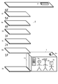
- FIG. It is a figure which shows the elevator apparatus in Embodiment 1.
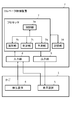
- FIG. It is a block diagram of the elevator apparatus in Embodiment 1.
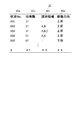
- FIG. It is a figure which shows the information of the database which stores the state information of the elevator apparatus in Embodiment 1.
- FIG. It is a flowchart which shows the control at the time of storing the state information of the elevator apparatus in Embodiment 1.
- FIG. It is a flowchart which shows the control at the time of the fixed information storage of the elevator apparatus in Embodiment 1.
- FIG. It is a figure which shows the information of the database which stores the definite information of the elevator apparatus in Embodiment 1.
- FIG. It is a figure which shows the information of the database which stores the aggregated information of the elevator apparatus in Embodiment 1.
- FIG. 1 It is a flowchart which shows the control at the time of the destination floor candidate prediction of the elevator apparatus in Embodiment 1. It is a figure which shows the button type destination navigation device when one passenger boarded in Embodiment 1. FIG. It is a figure which shows the button type destination navigation device when a plurality of passengers boarded in Embodiment 1.
- FIG. It is a figure which shows the information of the database which stores the definite information of the elevator apparatus in Embodiment 2. It is a figure which shows the elevator apparatus in Embodiment 3.
- FIG. It is a figure which shows the information of the database which stores the correspondence table of the elevator apparatus in Embodiment 3. It is a flowchart which shows the control at the time of storing the state information of the elevator apparatus in Embodiment 3.
- FIG. It is a figure which shows the information of the database which stores the correspondence table of the elevator apparatus in Embodiment 3. It is a flowchart which shows the control of the correspondence table update of the elevator apparatus in Embodiment 4.
- FIG. It is a figure which shows the elevator apparatus in Embodiment 5. It is a block diagram of the elevator apparatus in Embodiment 5. It is a flowchart which shows the control at the time of storing the state information of the elevator apparatus in Embodiment 5. It is a figure which shows the temporary information when the car of the elevator apparatus in Embodiment 6 moves from the 1st floor to the 2nd floor. It is a figure which shows the temporary information when the car of the elevator apparatus in Embodiment 6 moves from the 2nd floor to the 3rd floor.
- Embodiment 1 The elevator device according to the first embodiment will be described in detail below with reference to the drawings.
- the same reference numerals in the drawings represent the same or equivalent configurations and steps.
- FIG. 1 is a diagram showing an elevator device according to the first embodiment. First, the entire elevator device will be described with reference to FIG.
- This elevator device includes a car 1, an elevator control device 2, a photographing device 4a which is a detection device 4, and a button-type destination navigation device 5a which is a display device 5, and floors from the 1st floor 3a to the 6th floor 3f. It is installed in a building having 3. Further, the car 1 is provided with a door 1a. In FIG. 1, three passengers 6, passenger A6a, passenger B6b, and passenger C6c, are in the car 1 accommodating a person, and the car 1 is stopped on the first floor 3a.
- the elevator control device 2 since the elevator control device 2 determines the passengers 6 on each floor 3 using the photographing device 4a, it is not necessary to provide the detection devices 4 at all the landings as in the prior art, and the number of detections is small.
- the device 4 can determine the disembarkation floor on which the passenger 6 disembarks. Further, the elevator control device 2 can predict the candidate of the destination floor for each passenger 6 and display it on the button-type destination navigation device 5a by using the determined disembarkation information.
- the elevator control device 2 includes a processor 7 for controlling, an input unit 8, an output unit 9 for outputting commands from the processor 7, and a storage unit 16 for storing information.
- the processor 7 is a CPU (Central Processing Unit), and is connected to an input unit 8, an output unit 9, and a storage unit 16 to exchange information.
- the processor 7 includes a control unit 7a, an identification unit 7b, a determination unit 7c, and a prediction unit 7d.
- the control unit 7a includes a software module that controls the identification unit 7b, the determination unit 7c, the prediction unit 7d, and the entire elevator device.
- the identification unit 7b includes a software module that acquires identification information for identifying the passenger 6 from the detection information detected by the detection device 4 described later.
- the acquisition of the identification information means that the facial information of the passenger 6 which is the feature information is extracted from the image information captured by the photographing device 4a and stored in the extracted face information and the temporary storage destination of the storage unit 16. It means that the face information newly extracted as a result of the face recognition is stored in the temporary storage destination of the storage unit 16 as the identification information by collating with other face information by the two-dimensional face recognition.
- the facial information is information about the positions of feature points such as the eyes, nose, and mouth of the face.
- the determination unit 7c includes a software module that determines the disembarkation floor of each passenger 6 from the change of the identification information 10c and the departure floor information 10b in two consecutive states stored in the state information database 10 described later. ..
- the prediction unit 7d is provided with a software module that predicts the candidate floor 13 which is a candidate for the destination floor from the aggregated information database 12 described later.
- the input unit 8 is an input interface provided with a terminal for connecting an electric wire (not shown) connected to the detection device 4 and the display device 5.
- the input unit 8 also includes a terminal for connecting an electric wire connected to a drive device (not shown) that opens / closes / moves the door 1a of the car 1.
- the output unit 9 is an output interface provided with a terminal for connecting an electric wire (not shown) connected to the display device 5.
- the output unit 9 also includes a terminal for connecting an electric wire connected to a drive device (not shown) that opens / closes / moves the door 1a of the car 1.
- the storage unit 16 is a storage device composed of a non-volatile memory and a volatile memory.
- the non-volatile memory stores the state information database 10, the definite information database 11, and the aggregated information database 12, which will be described later.
- the volatile memory temporarily stores information generated by the processing of the processor 7 and information input to the elevator control device 2 from the photographing device 4a and the button-type destination navigation device 5a. Further, the temporarily stored information may be stored in the non-volatile memory.
- the photographing device 4a which is the detection device 4 is a camera installed on the upper part of the car 1 on the door 1a side, facing the front side when looking at the inside of the car 1 from the door 1a.
- the photographing device 4a constantly photographs the state in the car 1 and transmits the captured moving image to the elevator control device 2.
- the button-type destination navigation device 5a is an output device for transmitting information to the passenger 6, and displays the candidate floor 13 predicted by the prediction unit 7d and output by the output unit 9.
- the button-type destination navigation device 5a also functions as an input device when the passenger 6 registers the destination floor.
- the state information database 10 is a database that stores state information including the identification information acquired by the identification unit 7b for each state of the car 1.
- each state refers to the inside of the car 1 from the closing of the door on one floor 3 to the opening of the door on another floor 3 when the car 1 moves from one floor 3 to another. It means each state. That is, one state information includes information on the movement of the car 1 and identification information including the movement, which is acquired in a state where the passenger 6 does not enter or exit from the closing of the door to the opening of the door.
- the state information database 10 gets on the state number 10a, which is a serial number for each state, the departure floor information 10b, which is the floor 3 where the car 1 for each state has started moving, and the car 1 for each state. It is a database including identification information 10c which is identification information acquired from the passenger 6 and movement direction information 10d indicating the direction in which the car 1 has moved for each state, and is added by the identification unit 7b.
- the state information in which the state number 10a is X is represented as the state X.
- FIG. 3 shows that the information acquired from the closing of the door to the opening of the door, including the movement of the first car 1, is regarded as the state 001, and in the state 001, the car 1 starts moving in the ascending direction from the first floor 3a without the passenger 6. Shown. Further, the state 002 indicates that the car 1 has started moving in the ascending direction from the second floor 3b with the passenger A6a having the identification information of "A” and the passenger B6b having the identification information of "B". ..
- the identification information is face information
- the notations "A" and “B” are a combination of a plurality of face information obtained from each specific passenger 6.
- the identification information of "C” was possessed. This indicates that passenger C6c has started moving in the ascending direction from 3c on the 3rd floor.
- the state 004 indicates that in the state 003, a passenger having the identification information of "D” who was not in the car 1 has newly boarded.
- the passenger B6b having the identification information of "B” and the passenger C6c having the identification information of "C” who were in the car 1 in the state 003 are not in the car 1 in the state 004. ing.
- the passenger B6b having the identification information "B” and the passenger C6c having the identification information "C” are in the state by using only the change of the identification information acquired from the image information detected by the photographing device 4a. It can be seen that the passenger got off at 3e on the 5th floor, which is the departure floor of 004.
- FIG. 4 is a flowchart showing the control of the elevator device when the information in the car 1 is acquired.
- the photographing device 4a constantly photographs the inside of the car 1 and transmits the captured moving image to the elevator control device 2.
- step S11 the control unit 7a outputs a command for closing the door 1a of the car 1 from the output unit 9 to the drive device, and when the door closing is completed, the process proceeds to step S12.
- step S12 the control unit 7a stores the floor information about the floor 3 in which the car 1 is stopped in the temporary storage destination of the storage unit 16. After that, in step S13, the control unit 7a starts the movement of the car 1 by outputting a command from the output unit 9 to the drive device, and proceeds to step S14.
- step S14 the control unit 7a causes the identification unit 7b to extract the identification information.
- the identification unit 7b acquires image information taken by the photographing device 4a and stored in the storage unit 16 via the input unit 8, and features facial information which is information on the facial feature points of the passenger 6 from this image information. Extract as information.
- the identification unit 7b detects edge pixels using a sobel filter on the acquired image information, and calculates a feature amount such as a brightness distribution of the edge pixels.
- a partial image whose feature amount satisfies a predetermined condition considered to correspond to a human face stored in advance in the storage unit 16 is detected as a partial image showing the human face.
- the feature points of the passenger 6 which are the face information are extracted from the detected partial images by using the plurality of reference face images stored in the storage unit 16 in advance.
- the position where the difference between the image features such as the brightness value and the hue value at the feature points preset in the reference face image is detected. Identify from the partial image. This identification is performed for a plurality of reference facial images according to the positional relationship between the feature points (for example, the outer corner of the eye is outside the inner corner of the eye). Then, the position where the sum of the differences with respect to the plurality of reference face images is minimized is set as the position of the feature point in the detected partial image.
- Image features such as luminance value and hue value, which are information on feature points at this time, and relative distances from other feature points are acquired as face information.
- preprocessing for correcting the difference depending on the shooting angle of the face, and then perform the above-mentioned feature point extraction.
- the feature information may be extracted by a method other than the above as long as the information can be extracted from the image.
- the face image may be preprocessed to convert the face into an image viewed from the front, and the converted image may be input to the trained model of machine learning to extract feature information. This makes it possible to extract feature information that is resistant to changes in the shooting angle of the face.
- the image information transmitted by the photographing device 4a may be compressed image information such as Motion JPEG, AVC, HEVC, or uncompressed image information.
- the processor 7 restores the original image from the compressed image using a known decoder and uses it for the above-mentioned face information extraction.
- step S15 the identification unit 7b accesses the storage unit 16 and collates whether the face information extracted in step S14 has already been extracted with the face information stored in the temporary storage destination of the storage unit 16. Judgment by doing. The verification is performed by two-dimensional face recognition. As a result of collation, if the same face information is not stored in the temporary storage destination, it is determined that the face information has been extracted for the first time, and the process proceeds to step S16. The process proceeds to step S17. That is, if the face information extracted in step S14 and the face information having a similarity equal to or greater than the threshold value are stored in the temporary storage destination, the process proceeds to step S17.
- the threshold value of this similarity can be experimentally determined by using an image in which a plurality of people are placed in a basket. For example, in order to prevent the detection omission of the passenger 6 by determining that another passenger 6 is the same person, a high degree of similarity is set as a threshold value. On the other hand, if it is desired to reduce the possibility of detecting the same passenger 6 as another person, a low similarity is set as a threshold value.
- a trained model of machine learning may be used to determine whether or not they are the same. Two images or features to be compared by supervised learning using multiple images with different brightness such as shooting angle, facial expression, lighting, etc. for the same person, or feature quantities extracted from them. It is possible to more accurately determine whether the amounts belong to the same person.
- the identification unit 7b identifies the number of passengers 6 in the car 1, and when the number of face information stored in the temporary storage destination reaches the number of passengers 6 in the car 1, the process may proceed to step S18. good.
- step S16 the identification unit 7b stores the face information acquired in step S14 in the temporary storage destination of the storage unit 16.
- step S17 the process proceeds to step S17, and if the car 1 is not stopped, the process returns to step S14, and the processing for the partial image of the face of another passenger 6 and the image of the next image frame is repeated. If the car 1 is stopped, the process proceeds to step S18. That is, by repeating steps S14 to S17, the face information extracted even once during the movement of the car 1 is stored in the temporary storage destination.
- the identification unit 7b stores the state information in the state information database 10 and erases the information of the temporary storage destination. Specifically, the state information having a number one higher than the state number 10a having the largest value is created. Then, in the newly created state information, the information of the floor 3 stored in the temporary storage destination in step S12 is stored in the state information database 10 as the departure floor information 10b. Further, the identification unit 7b identifies the face information of one or a plurality of passengers 6 stored in the temporary storage destination in step S16 as the identification information 10c corresponding to each passenger 6, and identifies these identified identification information 10c. Stored in the state information database 10.
- the identification unit 7b stores the moving direction of the car 1 from step S13 to step S17 as the moving direction information 10d.
- the control unit 7a outputs a command to open the car 1 from the output unit 9 to the drive device, and ends the control of information acquisition in the car 1.
- the flow start of FIG. 4 is started again, the door closing in step S11, and the information acquisition of the car 1 in step S12 are performed. Therefore, the identification unit 7b repeatedly acquires the identification information every time the car 1 moves. According to the above, it is possible to acquire and store the identification information of the passenger 6 who is in the car 1 in a certain state from the door closing to the door opening including the movement of the car 1.
- the definite information database 11 is a database in which the definite information is stored by the determination unit 7c each time the state information is added to the state information database 10.
- the control shown in FIG. 5 is performed every time the state information is added to the state information database 10, but of course, it may be performed collectively at the end of the day or the like.
- FIG. 5 is a flowchart showing the control of the elevator device when storing the definite information.
- the control unit 7a causes the determination unit 7c to determine the disembarkation floor from the status information stored in the status information database 10.
- the determination unit 7c gets off one or a plurality of passengers 6 by taking the difference of the identification information 10c in the state information indicating the two states to which two consecutive state numbers 10a stored in the state information database 10 are assigned. judge. That is, the state X-1 indicating the first state from the closing of the door to the opening of the door including the movement of the car 1 and the second state from the closing of the door to the opening of the door including the movement of the next car 1
- the disembarkation of the passenger 6 is determined by taking the difference of the identification information 10c from the indicated state X. That is, if the identification information stored in the identification information 10c in the first state is not stored in the identification information 10c in the second state, it is determined that the passenger 6 having the identification information has disembarked. do.
- the determination unit 7c determines which floor the passenger 6 who disembarked is on which floor the departure floor information 10b in the state X, which indicates the floor 3 on which the car 1 starts moving in the second state, is determined as the disembarkation floor. Determine if you got off at 3.
- step S22 the determination unit 7c stores the disembarking floor, the disembarked passenger 6, and the moving direction information 10d of the state X-1 indicating the moving direction of the car 1 immediately before the passenger 6 disembarks in the confirmation information database 11. do.
- the information stored in the definite information database 11 will be described with reference to FIG.
- the confirmation information database 11 includes a confirmation number 11a which is a serial number, a disembarkation floor information 11b, a passenger information 11c, and a direction information 11d.
- a confirmation number 11a which is a serial number
- a disembarkation floor information 11b which is a serial number
- a passenger information 11c which is a passenger information
- a direction information 11d the definite information in which the definite number 11a is Y is represented as definite Y.
- the confirmation number 11a corresponds to two consecutive state numbers 10a of the state information database 10.
- the confirmation 001 of the confirmation information database 11 is information determined by the determination unit 7c from the states 001 and the state 002 of the state information database 10 in FIG.
- the disembarkation floor information 11b is information indicating the floor 3 on which the passenger 6 determined by the determination unit 7c has disembarked, and the passenger information 11c indicates the identification information of the passenger 6 disembarking on the floor 3.
- the direction information 11d is the moving direction of the car 1 immediately before stopping at the floor 3 indicated by the disembarkation floor information 11b. That is, the direction information 11d of the fixed 001 is the movement direction information 10d of the state 001.
- the passenger 6 has not disembarked on the second floor 3b, which is the floor 3 that departed in the state indicated by the state 002, and the moving direction of the car 1 immediately before stopping at the second floor 3b is the state 001. It indicates that it is an ascending direction, which is a moving direction.
- the confirmation 003 is the 5th floor 3e, which is the floor 3 that departed in the state indicated by the state 004, and the passenger B6b having the identification information of "B” and the passenger C6c having the identification information of "C” It indicates that the moving direction of the car 1 immediately before stopping on the 5th floor 3e after getting off is the ascending direction which is the moving direction in the state 003.
- step S22 the determination unit 7c creates confirmation information having a number one larger than the one with the largest confirmation number 11a. Then, in the newly created confirmation Y, the determined disembarkation floor is used as the disembarkation floor information 11b, the identification information of the passenger 6 who disembarked is used as the passenger information 11c, and the state X-1 indicating the first state is used.
- the moving direction information 10d of the above is stored as the direction information 11d.
- step S23 the control unit 7a refers to the confirmed information of the newly added confirmation information database 11 and updates the aggregation information database 12.
- the aggregated information database 12 is a history of getting off the passenger 6.
- the aggregated information database 12 is a database created for each moving direction of the car 1, and the number of times of getting off on each floor 3 is counted for each identification information of the passenger 6.
- FIG. 7 is a count of the number of disembarkations during the ascending movement of the car 1.
- Passenger A6a having the identification information "A" indicates that the number of disembarkations on the 5th floor 3e is 100 times.
- step S23 the control unit 7a refers to the direction information 11d of the finalized information and determines the aggregated information database 12 to be updated.
- the aggregated information database 12 when the car 1 is ascending is determined as the update target.
- the number of disembarkation times of the disembarking passenger 6 for each disembarkation floor is counted up.
- the control unit 7a collates the passenger information 11c with the identification information of the passenger 6 stored in the aggregated information database 12 by two-dimensional face authentication. If the matching passenger 6 is stored as a result of the collation, the number of disembarkation assigned to the floor 3 indicated by the disembarkation floor information 11b of the confirmed information is counted up from the number of disembarkation of the passenger 6 for each disembarkation floor. .. On the other hand, if the matching passenger 6 is not stored, the passenger 6 having the passenger information 11c of the confirmed information as the identification information is newly added to the aggregated information database 12, and the number of times of getting off the floor 3 indicated by the disembarkation floor information 11b is added. Is 1.
- the aggregation information database 12 when the car 1 moves up is updated. Since the disembarkation floor information 11b of the confirmed 003 is the 5th floor 3e and the passenger information 11c is "B" and "C", the passengers B6b and "C” having the identification information of "B” in the aggregated information database 12 The numerical value indicating the 5th floor 3e of the passenger C6c having the identification information is counted up by 1.
- the identification unit 7b of the elevator device acquires identification information for each state from the image captured by the photographing device 4a. That is, when the car 1 moves from one floor 3 to another floor 3, the identification information can be acquired in a state where the passenger 6 does not enter or exit from the closing of the door to the opening of the door, including the movement. Further, the identification unit 7b repeatedly acquires the identification information for each state, so that the determination unit 7c determines the change of the identification information in the plurality of states and the disembarkation floor of the passenger 6 from the floor 3 where the car 1 is stopped. can do.
- the detection device 4 and the elevator control device 2 installed in the car 1 without installing the detection device 4 on the landing side. can. Therefore, the cost for installation and maintenance is low. Further, in an elevator device in which a security camera or the like is already installed in the car 1, passenger 6 can simply rewrite the software installed in the elevator control device 2 without installing a new device. The history of getting off can be stored.
- the portable information processing device since the portable information processing device is used to store the usage history of the elevator device, the usage history can be stored only by the user who carries the portable information processing device. Was there. However, according to the present embodiment, it is possible to memorize the getting-off floor of the elevator user without giving the passenger 6 anything.
- the disembarkation history is stored in the aggregated information database 12 for each acquired identification information. Therefore, it is not necessary to set in advance the information of the target for storing the disembarkation history, and the disembarkation history of the unspecified passenger 6 can be stored.
- the aggregated information database stores the history for each ID (Identification) of the passenger 6
- the storage unit 16 stores in advance what kind of face information the passenger 6 corresponding to the ID has. It is necessary to memorize it. Therefore, the history of the passenger 6 which has not been set in advance was not saved. If the history is stored for each identification information as in the present embodiment, the operation of storing the face information of the passenger 6 corresponding to the ID becomes unnecessary.
- the history is stored for each face information which is the identification information of the passenger 6. Therefore, the passenger 6 does not have to set his / her face information and the history is created.
- FIG. 8 is a flowchart showing the control of the elevator device at the time of predicting the destination floor candidate.
- step S31 the control unit 7a causes the identification unit 7b to acquire the identification information.
- the identification unit 7b acquires an image from the photographing device 4a via the input unit 8 in the same manner as in step S14 of FIG. 6, and extracts the face information of the passenger 6 as identification information from the acquired image. Then, the face information is added to the temporary storage destination in the same manner as in step S16, and the process proceeds to step S32.
- step S32 the control unit 7a acquires the moving direction of the next car 1 and proceeds to step S33.
- the control unit 7a causes the prediction unit 7d to predict the candidate of the destination floor according to the number of disembarkation histories stored in the aggregated information database 12.
- the prediction unit 7d accesses the storage unit 16, refers to the aggregated information database 12 corresponding to the moving direction of the car 1 acquired by the control unit 7a in step S32, and corresponds to the identification information acquired by the identification unit 7b in step S31.
- the floor 3 on which the passenger 6 having the identification information gets off most is specified.
- the prediction unit 7d predicts that the specified floor 3 is the candidate floor 13 and is the destination floor of the passenger 6.
- the square in FIG. 7 shows the floor 3 where each passenger 6 got off the most, and is the candidate floor 13 which is a candidate for the destination floor predicted by the prediction unit 7d in the present embodiment.
- step S34 the control unit 7a acquires the current floor 3 and determines whether the candidate floor 13 predicted in step S33 is in the moving direction of the car 1 acquired in step S32 from the current floor 3. do. If the candidate floor 13 is a movable floor 3, the process proceeds to step S35, and if the candidate floor 13 is an impossible floor 3, the process proceeds to step S36.
- the control unit 7a executes the process of step S35.
- step S35 the control unit 7a outputs a command for displaying the candidate floor 13 to the button-type destination navigation device 5a, which is the display device 5, via the output unit 9.
- FIG. 9 shows a display example of the button-type destination navigation device 5a when the candidate floor 13 is output.
- the left figure of FIG. 9 shows a display example of the button-type destination navigation device 5a in which the candidate floor 13 is not displayed, and the central view of FIG. 9 shows a display example when the 5th floor 3e is predicted as the candidate floor 13.
- the central view of FIG. 9 shows that the button corresponding to the floor 3 which is the candidate floor 13 blinks.
- step S35 at the same time as the output of the candidate floor 13, the control unit 7a starts the timer referred to in step S37, which will be described later. It should be noted that this timer starts every 3 floors that are candidates for output.
- step S36 the control unit 7a confirms whether the button on the destination floor is pressed via the input unit 8. That is, if the signal of pressing the button on the destination floor is not output from the button-type destination navigation device 5a to the input unit 8, the process proceeds to step S37, and if so, the process proceeds to step S38.
- step S37 the control unit 7a determines whether a certain time, for example, 5 seconds or more has elapsed since the timer started. If the elapsed time is 5 seconds or more, the control unit 7a executes the process of step S38, and if the elapsed time is less than 5 seconds, the control unit 7a executes the process from step S31 again.
- step S38 the control unit 7a registers the floor 3 assigned to the candidate floor 13 output in step S35 or the button determined to have been pressed in step S36 as the destination floor.
- a display example of the button-type destination navigation device 5a when the destination floor is registered is shown in the right figure of FIG.
- the right figure of FIG. 9 shows that the button corresponding to the destination floor changes from blinking to lit.
- this button-type destination navigation device 5a displays a plurality of candidate floors 13 when a plurality of candidate floors 13 are predicted.
- FIG. 10 shows a button-type destination navigation device 5a when a plurality of candidate floors 13 are predicted.
- the central view of FIG. 10 shows a display example of the button-type destination navigation device 5a when it is predicted that the third floor 3c is a candidate floor for passenger 6 and the fifth floor 3e is a candidate floor for another passenger 6. ..
- the buttons indicating the 3rd floor 3c and the 5th floor 3e are blinking.
- buttons indicating the 5th floor 3e as the destination floor is subsequently pressed by the passenger 6, and the 5th floor pressed by the passenger 6.
- the button indicating 3e changes from blinking to lit, and the unpressed 3rd floor 3c continues blinking.
- the user of the elevator device does not have to register the candidate floor 13 by himself / herself in advance, and the candidate floor 13 is set by prediction. Further, according to the present embodiment, even when a plurality of passengers 6 board the elevator device, the candidate floor 13 can be predicted for all the passengers 6.
- this embodiment it is possible to register the destination floor without having to press the button on the destination floor when using the elevator.
- the disembarkation floor is stored by the disembarkation determination using the camera, and the disembarkation history used for the prediction of the candidate floor 13 is created. Therefore, this elevator device can determine the destination floor of the passenger 6 more accurately.
- Embodiment 2 is an elevator device that determines the boarding floor by using the same method as that of the first embodiment and stores it together with the disembarking floor information 11b.
- the differences from the first embodiment will be mainly described.
- FIG. 11 the same reference numerals as those in FIG. 6 represent the same or corresponding parts.
- the determination unit 7c is software that determines the disembarkation floor and the boarding floor of each passenger 6 from the change of the identification information 10c and the departure floor information 10b in two consecutive states stored in the state information database 10 shown in FIG. It has a module.
- step S21 of the first embodiment the disembarkation floor is determined from two consecutive states of the state information database 10, but in the present embodiment, the determination unit 7c also determines the boarding floor.
- the identification information is stored in the identification information 10c of the state X indicating the second state.
- Passenger 6 with the passenger 6 is determined to have boarded the car 1.
- the determination unit 7c determines that the departure floor information 10b in the state X-1 indicating the floor 3 on which the car 1 starts moving in the first state is the boarding floor.
- the determination unit 7c stores the determination information of the determined boarding floor and the passenger 6 who has boarded in the temporary storage destination of the storage unit 16.
- the determination unit 7c stores the identification information of the passenger 6 who got off in the temporary storage destination by the two-dimensional face authentication. Match with the identification information of.
- the determination unit 7c stores the boarding floor of the matched passenger 6 and the identification information of the passenger 6 in the definite information database 19 shown in FIG. 11 as boarding / alighting information 11e.
- the definite information database 11 stores passenger information 11c and direction information 11d together with the disembarkation floor information 11b.
- the definite information database 19 includes the disembarkation floor information 11b and the floor 3 on which the passengers who disembarked on the floor 3 indicated by the disembarkation floor information 11b. It is stored as boarding / alighting information 11e. Confirmation 003 in FIG. 11 indicates that on the 5th floor 3e, the passenger B6b having the identification information of'B'boarded on the 2nd floor 3b and the passenger C6c boarding on the 3rd floor 3c of the passenger C6c got off. There is.
- step S23 the control unit 7a refers to the confirmed information of the newly added confirmed information database 19 and updates the aggregated information database 12.
- the aggregated information database 12 to be updated based on the boarding floor is determined with reference to the boarding / alighting information 11e of the passenger 6.
- the aggregated information database 12 shown in FIG. 7 aggregates the disembarkation floors of the passengers 6 for each moving direction of the car 1, but in the present embodiment, the passengers 6 are aggregated for each passenger floor of the passengers 6. It is a total of the getting-off floors of.
- the boarding floor can be determined using the same method and device as in the first embodiment. Further, by storing it together with the getting-off floor and selecting and referring to the aggregated information database 12 corresponding to the boarding floor of the passenger 6 which is the prediction target of the destination floor in step S33 of FIG. 8, the prediction of the destination floor is made. Can be done more accurately.
- Embodiment 3 by acquiring information that can be easily acquired such as the color of the clothes of the passenger 6, the passenger 6 is identified such as the face information during the period from the closing of the door to the opening of the door, including the movement of the car 1. Even if it is not possible to obtain easy identification information, the disembarkation floor can be determined. For example, when the face information is used as the identification information, the face information may not be acquired because the face of the passenger 6 is facing in the direction opposite to the installation location of the camera. In this embodiment, even if the face information cannot be acquired, the passenger 6 is identified by acquiring other image information that can identify the passenger 6 in the car 1, and the disembarkation floor of the passenger 6 is determined. ..
- the differences from the first embodiment will be mainly described.
- FIG. 12 the same reference numerals as those in FIG. 1 represent the same or corresponding parts.
- the elevator device shown in FIG. 12 is different from the entire elevator device shown in FIG. 1 according to the first embodiment. It is installed like this.
- the identification unit 7b acquires the face information of the passenger 6 which is the feature information from the image information photographed by the photographing device 4a.
- the identification unit 7b identifies the other feature information of the passenger 6 as additional feature information.
- the identification unit 7b includes a software module that acquires the identification information when any of the face information 14b and the additional feature information 14c is extracted.
- Correspondence table 14 to be described later is stored in the storage unit 16.
- the information stored in the correspondence table 14 will be described with reference to FIG.
- Correspondence table 14 is a database that stores face information 14b and additional feature information 14c possessed by the same passenger 6.
- the correspondence table 14 is composed of the correspondence number 14a which is a serial number, the face information 14b extracted by the identification unit 7b, and the additional feature information 14c specified by the identification unit 7b.
- This additional feature information 14c is the color of the clothes in the present embodiment and includes information on the back view of the passenger 6.
- FIG. 14 is a flowchart showing the control of the elevator device at the time of information acquisition of the present embodiment.
- the processor 7 starts this control with the car 1 stopping on one of the floors 3 and the door 1a open.
- the identification unit 7b extracts the face information 14b in the same manner as in step S14 of the first embodiment, and proceeds to step S42.
- the extracted face information 14b is, for example, the face information 14b of the passenger 6 who gets into the car 1.
- the photographing device 4a is provided at a position where the passenger 6 can photograph his / her face when he / she gets into the car 1.
- the face information 14b can be acquired for the passenger 6 who has already boarded the car 1, but the face information may not be acquired if the face is not facing the direction of the photographing device 4a.
- step S42 the identification unit 7b collates whether the face information extracted in step S41 is stored in the correspondence table 14 by two-dimensional face authentication. If it is not stored, the process proceeds to step S43, and if it is already stored in the correspondence table 14, the process proceeds to step S45.
- the identification unit 7b identifies additional feature information of the passenger 6 having the face information extracted in step S41, and proceeds to step S44.
- the identification unit 7b has a width of 50 cm at a portion having a certain positional relationship (for example, at an actual distance of 10 cm to 60 cm below the human face) from the partial image showing the human face detected in step S14. From the image of the region), the partial image showing the clothes is detected by the same process as the partial image showing the human face in step S14. Then, the color information which is the average of the hue values in the partial image is regarded as the color of the clothes, and the additional feature information of the passenger 6 is specified. In many cases, the color of the clothes seen from the front including the face of the passenger 6 and the color of the clothes seen from the back of the passenger 6 are the same, so that the color of the clothes includes the information of the back view of the passenger 6.
- step S44 the identification unit 7b adds the correspondence between the face information 14b and the additional feature information 14c to the correspondence table 14.
- step S45 the control unit 7a determines whether to close the car 1. This determination is made based on, for example, the time since the door 1a is opened, the motion sensor provided on the door 1a, the presence or absence of pressing the door closing button provided on the button-type destination navigation device 5a, and the like.
- the control unit 7a executes the process of step S11, and if the door 1a is not closed yet, returns to step S41 and repeats the same process in order to detect the feature information of another passenger 6. ..
- step S11 the control unit 7a controls the car 1 and the like in the same procedure as in the first embodiment.
- step S14a the identification unit 7b extracts the face information 14b as in step S14 of the first embodiment, and extracts additional feature information 14c as in step S43.
- step S15a the identification unit 7b determines whether the face information 14b extracted in step S14a is already stored in the temporary storage destination, as in step S15 of the first embodiment.
- the identification unit 7b refers to the correspondence table 14 and determines whether the face information 14b corresponding to the additional feature information extracted in step S14a is already stored in the temporary storage destination. That is, it is determined whether or not there is one or a plurality of feature information 14c stored in the correspondence table 14 that matches or is similar to the additional feature information extracted in step S14a.
- step S15 of the first embodiment it is determined in the same manner as in step S15 of the first embodiment whether the face information 14b stored in association with the extracted additional feature information 14c that matches or is similar to the extracted additional feature information is stored in the temporary storage destination. do. Judgment of similarity of additional feature information is made by whether the difference in color information is within or below the threshold.
- the threshold value is, for example, the angle of the hue circle, and the difference in hue within 30 degrees is determined to be similar as within the threshold value.
- step S16 When the face information 14b matching the extracted face information or the face information 14b corresponding to the extracted additional feature information is not already stored in the temporary storage destination, that is, when the determination in step S15a is Yes, the identification unit 7b , The process of step S16 is executed.
- the identification unit. 7b executes step S16. If the determination in step S15a is No, the identification unit 7b skips the process in step S16 and executes the process in step S17.
- step S16 if the face information is extracted in step S14a, the identification unit 7b stores the face information in the temporary storage destination as in the first embodiment. If the feature information 14c is extracted in step S14a, the face information 14b corresponding to the extracted feature information 14c is stored in the temporary storage destination with reference to the correspondence table 14.
- the identification unit 7b of this embodiment is the passenger 6 who is riding the passenger 6 in the car 1 if there is information that can identify the passenger 6 even with only one type of the identification information of the plurality of types. To identify. Therefore, for example, even if the face cannot be photographed by the photographing device 4a, the passenger 6 in the car 1 can be identified if the color information such as clothes can be acquired.
- step S18 the identification unit 7b stores the face information stored in the temporary storage destination as the identification information 10c in the state information database 10 as shown in FIG. 3, and erases the information of the temporary storage destination.
- step S46 the identification unit 7b collates the identification information 10c of the state information newly stored in step S18 with the face information 14b stored in the correspondence table 14 by two-dimensional face authentication. If any of the face information 14b stored in the correspondence table 14 is not in the identification information 10c, the process proceeds to step S47, and if all of the face information is stored, the process proceeds to step S19.
- step S47 the control unit 7a deletes the corresponding information corresponding to the face information 14b that was not stored in the state information database 10 in step S18. That is, after step S11, the passenger 6 for which neither the face information 14b nor the additional feature information 14c has been acquired is deleted from the correspondence table 14.
- step S19 as in the first embodiment, the control unit 7a opens the car 1 and ends the control of information acquisition in the car 1.
- the operation of acquiring the information of the car 1 was started again when the door was closed next time, but in the present embodiment, the operation of acquiring the next information is immediately started. .. At this time, the information in the correspondence table 14 is taken over by the next operation of acquiring information.
- the identification information not only the face information 14b acquired when the passenger 6 gets in the car 1 but also the additional feature information 14c acquired when the passenger 6 does not enter and exit from the closing of the door to the opening of the door is also the identification information. It can be used as feature information for specifying 10c. That is, even if the face information 14b, which is easy to identify the passenger 6 such as the face information, cannot be obtained between the closing of the door and the opening of the door, including the movement of the car 1, the color of the clothes is similar. By acquiring the feature information 14c, which is easy-to-acquire identification information regardless of the orientation of the passenger 6, the disembarkation floor can be determined by using the same method as in the first embodiment.
- the disembarkation floor is determined even when the photographing device 4a is installed so that the door 1a side of the car 1 can be photographed. be able to.
- the identification of the passenger 6 by the additional feature information 14c can be performed by the elevator device. If the passenger 6 having a capacity of about 6 can be identified, the passenger 6 can be accurately identified. Therefore, it is possible to more accurately obtain the disembarkation history by using information such as the color of clothes that can be easily obtained regardless of the posture and orientation of the person.
- Embodiment 4 the passenger 6 who has once acquired the identification information is tracked by the image recognition process, so that the identification information cannot be acquired every time from the closing of the door to the opening of the door, including the movement of the car 1. Also, the disembarkation floor can be determined.
- the case where the face information cannot be acquired by using the feature information such as color is supplemented, but in this embodiment, the coordinate information of the passenger 6 in a plurality of images is used as additional feature information, and the passenger By tracking the coordinates of 6, the disembarkation floor of the passenger 6 is determined.
- the differences from the first embodiment will be mainly described.
- the identification unit 7b acquires the face information of the passenger 6 which is the identification information from the image information photographed by the photographing device 4a.
- the identification unit 7b includes a software module that tracks the passenger 6 by image recognition processing, face information that is characteristic information of the passenger 6, and coordinate information of the passenger 6 that is being tracked. It is provided with a software module for storing the above in the correspondence table 20 and a software module for acquiring identification information when the passenger 6 is traceable.
- the correspondence table 20 is stored in the temporary storage destination of the storage unit 16.
- a correspondence table 20 used for tracking the passenger 6 will be described with reference to FIG.
- the face information 14b and the additional feature information 14c are stored in association with each other.
- the correspondence table 20 in the present embodiment stores the coordinate information 14d of the passenger 6 in association with the face information 14b which is the feature information, and is composed of the correspondence number 14a, the face information 14b and the coordinate information 14d. ..
- FIG. 16 is a modification of the processing of the broken line portion of FIG. 4, and is a flowchart showing a control for updating the identification information using the coordinate information.
- the identification unit 7b of the elevator device recognizes the passenger 6 by image recognition processing from the image taken by the photographing device 4a, and constantly updates the current coordinates which are the current position information of the recognized passenger 6. Is being tracked by. That is, the identification unit 7b repeatedly acquires the coordinate information to identify the same passenger 6 as the specific passenger 6 whose coordinate information was acquired before the previous coordinate acquisition.
- step S11 to step S13 in FIG. 4 When the processes from step S11 to step S13 in FIG. 4 are executed, the processor 7 executes the process in FIG. 16 instead of steps S14 to S16 shown by the broken line in FIG.
- the control unit 7a causes the identification unit 7b to extract face information and coordinate information.
- the identification unit 7b reads out the image information captured by the photographing device 4a from the storage unit 16 and performs pattern matching on the image information.
- the contour line extraction process is performed on the image information, and the contour line data is collated with the contour line data representing the shape of the human head.
- the contour line data used for collation is data showing, for example, the outer shape of the average human head, for example, an elliptical shape, and the image can be detected even if the head is facing forward, sideways, or backward. Is.
- the identification unit 7b acquires the data of the contour lines of one or a plurality of heads and their coordinate information.
- the identification unit 7b performs the same processing as in step S14 of FIG. 4 on one of the acquired contour line data, and extracts face information. If the passenger 6 is not facing the installation direction of the photographing device 4a, the face information may not be extracted. In that case, the identification unit 7b uses the fact that the face information could not be extracted as the face information. Hold. For example, when the contour line data does not include data that matches the shape of the eyes, the identification unit 7b determines that the face information could not be extracted.
- the identification unit 7b determines whether the extracted face information could not be extracted, the extracted face information is new information, or is known information. Whether the extracted face information is new information or known information is determined by the identification unit 7b by referring to the correspondence table 20 of FIG. 15 and determined by the same algorithm as step S15 of FIG. NS. When the face information is new information, the identification unit 7b accesses the storage unit 16 in step S53, and the face information and the coordinate information are added to the correspondence table 20 of FIG. 15 together with the correspondence number.
- the identification unit 7b determines whether or not the processing has been performed on all the passengers 6 included in the extracted head contour data, that is, the image information, and if it is determined as No, the next passenger 6 In order to perform the identification process, the process returns to step S51 and the process is executed.
- step S52 When it is determined in step S52 that the face information is known, the process proceeds to step S55, and the identification unit 7b accesses the storage unit 16 and extracts the coordinate information 14d corresponding to the face information based on the face information in step S51. Rewrite to the coordinate information.
- the identification unit 7b accesses the storage unit 16 in step S56 and collates the coordinate information 14d in the correspondence table 20 with the acquired coordinate information. Then, the coordinate information 14d that meets the condition that the distance between the two is the closest within a certain threshold value is searched and specified.
- the "coordinate information 14d in the correspondence table 20" is the coordinate information acquired before the previous time
- the "acquired coordinate information” is the coordinate information acquired this time.
- the threshold value is, for example, a value corresponding to the typical width of a person's head or the frame rate of a moving image, for example, a predetermined value obtained by converting an actual distance within 10 cm into a distance in image information. Can be held as.
- the threshold value does not have to be a predetermined value, and may be specified by, for example, the processor 7 calculating this distance.
- step S57 the identification unit 7b rewrites the coordinate information 14d of the specified correspondence table 20 with the acquired coordinate information.
- the identification unit 7b executes the processing in step S58.
- the identification unit 7b identifies the information in which neither the face information 14b nor the coordinate information 14d is updated in steps S52 to S57, and the tracking of the specified information is interrupted. That is, it is deleted as information related to the passenger 6 who may have got off the car 1. As a result of this processing, only the information regarding the passenger 6 who is in the car 1 remains in the correspondence table 20. If it is determined in step S54 that the processing for all passengers has not been completed, the identification unit 7b returns to the processing in step S51 and repeats the same processing in order to recognize the next passenger.
- the processor 7 executes the process of step S17 of FIG. That is, the above-mentioned tracking process is executed until the car 1 is stopped.
- the identification unit 7b of the processor 7 stores the state information in the state information database 10 of FIG. 3 by the identification unit 7b using the face information 14b of the correspondence table 20 of FIG. Specifically, the identification unit 7b accesses the storage unit 16, reads all the face information 14b stored in the correspondence table 20, and uses the face information 14b as the identification information 10c of the state information database 10 in the storage unit 16.
- the identification unit 7b adds a line to FIG. 3 to create state information having a state number 10a that is one higher than that of the largest state number. Then, the acquired face information is added to the identification information 10c of the state information.
- the passenger 6 for the passenger 6 whose face information has been extracted even once, the correspondence between the current coordinate information and the face information 14b and the current coordinate information 14d is stored in the correspondence table 14 until the tracking is interrupted. Therefore, the passenger 6 can be identified by using the current coordinates of the passenger 6 as the identification information.
- the disembarkation floor can be determined even when information such as face information that can be easily identified by passenger 6 cannot be obtained every time between the closing of the car 1 and the opening of the car 1. For example, even if the face information 14b of the passenger A6a could not be acquired in the state 004 of FIG. 3, if the face information could be acquired in the state 002 or the state 003, the face information "A" of the passenger A6a could be obtained in the state 005. Since the associated passenger 6 can no longer be tracked, it is possible to determine whether the passenger A6a is getting off at the 6th floor 3f.
- step S56 when collating the coordinate information 14d, all the coordinate information 14d and the acquired coordinates are not collated, and the coordinate information 14d in which the face information is specified in the same image is excluded from the collation target. Can be. By doing so, the identification accuracy of the passenger 6 can be improved. Further, in the above description, the passenger 6 is tracked by associating the acquired coordinates with the coordinate information 14d having the closest distance, but the tracking method is not limited to this. For example, the distances between the coordinates and their total values are calculated for all patterns of the combination of the coordinates of the contour line data of the plurality of heads extracted from the image information and the coordinates of the plurality of coordinate information 14d in the correspondence table 20. , The combination pattern with the smallest total value may be used to track passenger 6.
- Embodiment 5 the information acquired by the receiving device 4b and the transmitting device 4c for wireless communication is used as additional feature information in addition to the image information acquired by the photographing device 4a, so that the vehicle can get off more accurately.
- the floor can be determined.
- the differences from the first embodiment will be mainly described.
- the car 1 of the elevator device of the present embodiment includes a receiving device 4b in addition to the photographing device 4a installed in the elevator device of the first embodiment.
- the receiving device 4b is an example of the detecting device 4, and receives the feature information transmitted from the transmitting device 4c carried by the passenger 6.
- the receiving device 4b detects and receives a management packet which is detection information transmitted from the transmitting device 4c by a wireless LAN (Local Area Network).
- This management packet contains a MAC (Media Access Control) address which is additional feature information.
- the receiving device 4b is connected to the input unit 8 of the elevator control device 2 by wire. The received management packet is transmitted to the input unit 8.
- the transmitting device 4c is a mobile information terminal (for example, a smartphone) carried by passenger 6. It keeps sending management packets including its own MAC address periodically.
- the elevator control device 2 includes an auxiliary storage unit 18 which is a non-volatile memory, in addition to the configuration of the first embodiment.
- the auxiliary storage unit 18 is provided with a database in which an identification number, which is identification information indicating the passenger 6, the face information of the passenger 6, and the MAC address of the mobile information terminal possessed by the passenger 6 are associated and stored in advance.
- the identification number may be stored in association with the face information and the MAC address and can distinguish the passenger 6, and the name of the passenger 6 or the like may be used instead of the identification number.
- the identification unit 7b is software that acquires the MAC address, which is the received feature information, from the management packet received by the receiving device 4b, in addition to the software module that acquires the feature information, which is the image feature information, from the image information detected by the photographing device 4a. It has a module.
- step S11 to step S14 the same reference numerals as those in FIG. 4 represent the same or equivalent steps.
- the same operations as those in the first embodiment are performed from step S11 to step S14.
- step S61 the identification unit 7b determines whether the feature information of the passenger 6 whose face information was extracted in step S14 has already been acquired. Specifically, the face information extracted in step S14 is collated with the face information stored in the database of the auxiliary storage unit 18, and the identification number of the passenger 6 corresponding to the matching face information is stored in the temporary storage destination of the storage unit 16. Check if it is remembered. If it is not stored, the process proceeds to step S62, and if it is stored, the process proceeds to step S63. In step S62, the identification unit 7b identifies the identification number of the passenger 6 corresponding to the face information extracted in step S14 as the information for identifying the passenger, and stores it in the temporary storage destination of the storage unit 16.
- step S63 the control unit 7a writes the management packet transmitted to the input unit 8 by the receiving device 4b in the storage unit 16. Then, the control unit 7a causes the identification unit 7b to acquire the MAC address which is additional feature information from the management packet, and proceeds to step S64.
- step S64 the identification unit 7b determines whether the feature information of the passenger 6 corresponding to the acquired MAC address has already been acquired. Specifically, the MAC address acquired in step S63 is collated with the MAC address stored in the auxiliary storage unit 18, and the identification number of the passenger 6 corresponding to the matching MAC address is stored in the temporary storage destination of the storage unit 16. Check if it is done. If the identification number is not stored, the process proceeds to step S65, and if it is stored, the process proceeds to step S17. In step S65, the identification unit 7b identifies the identification number of the passenger 6 corresponding to the acquired MAC address as information for identifying the passenger, and stores it in the temporary storage destination of the storage unit 16.
- the identification unit 7b stores the face information stored in the temporary storage destination as the identification information 10c in the state information database 10, but in step S18 of this embodiment, the face information is stored in the temporary storage destination.
- the identification number of the passenger 6 is stored in the state information database 10 as the identification information 10c.
- the identification information 10c used for determining disembarkation can be stored. Therefore, even when the face information of the passenger 6 cannot be acquired, the disembarkation floor can be determined more accurately by using the MAC address as the feature information as an auxiliary. Further, when predicting the destination floor, the destination floor can be predicted accurately based on the identification number specified from the face information or the identification number specified by the MAC address received by the receiving device 4b. In this case, in FIGS. 6, 7, and 11, the identification information is an identification number, and in the processing of FIGS. 5 and 8, the processor 7 controls using the identification number as the identification information.
- Embodiment 6 In the above-described embodiment, an example of determining the disembarkation floor or the like based on the difference in the identification information included in each state information has been described. The embodiment of specifying the getting-off floor by updating the information of the above will be described.
- FIGS. 20 to 22 are diagrams showing temporary information 15 stored in the storage unit 16.
- FIG. 20 shows temporary information 15 when the car 1 moves from the first floor to the second floor.
- the identification unit 7b of this embodiment detects the passenger A6a represented by the identification information "A” and the passenger B6b represented by the identification information "B” in the car, the temporary information 15 is as shown in FIG. To update. That is, when passengers A6a and passenger B6b get into the car 1 on the first floor, the identification information "A" and "B" are stored in the temporary information 15, and the floor information corresponding to each is stored as "2". NS. Similarly, FIGS.
- FIG. 21 and 22 show temporary information 15 when the car 1 moves from the second floor to the third floor, and temporary information 15 when the car 1 moves from the third floor to the fourth floor, respectively.
- the identification information “B” and “C” are detected in the car, so the identification information “C” is added as the temporary information 15.
- the floor information corresponding to the identification information "B” and “C” is updated to "3", respectively.
- the floor information corresponding to the identification information "A” is not updated and remains "2". This represents a situation in which the passenger A6a gets off the car 1 on the second floor and the passenger C6c represented by the identification information "C" gets into the car 1.
- FIG. 21 and 22 show temporary information 15 when the car 1 moves from the second floor to the third floor, and temporary information 15 when the car 1 moves from the third floor to the fourth floor, respectively.
- FIG. 21 and 22 show temporary information 15 when the car 1 moves from the second floor to the third floor, and temporary information 15 when the car 1 moves from the third floor to the fourth floor, respectively.
- the passenger 6 gets off by referring to the updated floor information.
- the floor can be specified.
- step S71 the identification unit 7b of the processor 7 acquires the image information captured by the imaging device 4a, which is the detection device 4. At this time, the identification unit 7b extracts images of a plurality of passengers 6 as partial images from the image information and specifies the number of passengers 6.
- the identification unit 7b performs image recognition processing on one of the extracted images of the plurality of passengers 6 to specify the identification information of the passengers 6.
- the image recognition process is performed in the same manner as in the above-described embodiment.
- the identification information may be face information or the identification number of the passenger 6.
- the identification unit 7b associates the identified identification information with the information on the floor at the time of image capture and stores it in the storage unit 16.
- Step S72 and step S73 are repeatedly executed for the number of people by loop processing via step S74. Therefore, other passengers B6b other than passenger A6a are also processed in the same manner, and the temporary information 15 is updated as shown in FIG.
- step S74 it is determined whether or not the identification unit 7b has processed the partial images for all 6 passengers. If it is determined to be Yes, the determination unit 7c determines whether the moving direction of the step S75 car 1 has changed. That is, it is determined whether the moving direction of the car 1 has changed from ascending to descending or from descending to ascending.
- the process returns to step S71 described above. That is, the same process as described above is repeated for the passenger 6 on the next floor. For example, suppose that passenger A6a gets off on the second floor, passenger C6c gets on, and car 1 goes up. In this case, the processes of steps S71 to S74 are executed again, and the information is updated as shown in FIG.
- the identification unit 7b does not update the floor information of the passenger A6a who got off on the second floor, but updates the information of the passenger B6b from the "second floor” to the "third floor”. Further, the identification unit 7b adds the identification information of the passenger C6c who got on the second floor and the floor information "third floor" to the temporary information 15.
- the determination unit 7c updates the update history stored in the storage unit 16 using the information of the temporary information 15 in step S76. For example, when passenger B6b gets off on the 3rd floor, passenger C6c gets off on the 4th floor, and all passengers 6 get off the car, the temporary information 15 is updated as shown in FIG. 22 before the execution of step S76. ing. In this temporary information 15, since the floor information represents the disembarkation floor of each passenger 6, in step S76, the determination unit 7c determines the disembarkation floor of each passenger using the information of the disembarkation floor of the temporary information 15, and implements it. The history information of the passenger 6 in the aggregated information database 12 of FIG. 12 is updated in the same manner as in the first embodiment. Specifically, the determination unit 17c counts up the number of disembarkations in the aggregated information database 12 corresponding to the identification information and the floor information.
- step S77 the determination unit 7c erases the information of each passenger 6 described in the temporary information 15 to prepare for the processing when the car is raised or lowered by the next landing call.
- step S77 ends, the process returns to step S71, and the processor 7 repeats the same process.
- the getting-off floor can be specified by updating the arrival floor of passenger 6 for each floor. It is not necessary to update the arrival floor for each floor, but it may be performed for each stop floor of the car. Further, in the above description, the characteristic treatment of the present embodiment has been focused on, but other treatments not described in this embodiment are performed in the same manner as in the other embodiments.
- Embodiment 7 the determination of the disembarkation floor or the like is carried out by a method different from that of the above-described embodiment.
- the method used here is a method of detecting the passenger 6 on the landing, that is, the floor 3 by the detection device 4 installed in the car 1 and identifying the boarding floor or the getting-off floor of the passenger 6. ..
- FIG. 24 is a diagram showing an image taken by the photographing device 4a, which is the detecting device 4 installed in the car 1.
- This image is an image taken in a situation where the platform can be seen through the entrance / exit of the car 1.
- the identification unit 7b of this embodiment recognizes the image of the passenger 6 included in the area 17 shown by the broken line in FIG. 24, and the determination unit 7c recognizes the passenger 6 on the floor based on the recognition result. Alternatively, identify the passenger 6 who got off.
- the image of the passenger 6 used for the collation of image recognition includes a forward-facing image and a backward-facing image of the passenger 6 for each passenger 6, and the collating image is the storage unit 16 or the auxiliary storage unit 18. It is remembered in.
- the determination unit 7c recognizes the floor on which the image was taken as the boarding floor of the passenger 6. Further, when the area 17 includes an image that matches the backward-facing image of the passenger 6, the determination unit 7c recognizes the floor on which the image was taken as the disembarkation floor of the passenger 6.
- step S81 the identification unit 7b of the processor 7 extracts an image of the landing that can be seen through the entrance / exit from the image taken by the photographing device 4a. Specifically, an image of a region surrounded by some coordinate points is extracted from the image. Since the photographing device 4a is fixed to the car, the coordinates of the above-mentioned coordinate points are fixed. Therefore, the identification unit 7b can specify the coordinate points by reading the coordinates set in advance in the storage unit 16. Then, the identification unit 7b extracts the image of the passenger 6 included in the extracted image as a partial image.
- the identification unit 7b executes the recognition process of the passenger 6 for this partial image by using the same algorithm as that of the first embodiment described above, that is, the pattern matching process between the acquired partial image and the image for matching. do.
- the identification unit 7b performs the recognition process using the forward-looking image of the passenger 6 as the collation image. Then, the identification unit 7b outputs the identification information of the passenger 6 as the recognition result.
- the identification information may be face information or the identification number of the passenger 6 associated with the collation image.
- the identification unit 7b outputs information indicating no match as a recognition result.
- step S83 the determination unit 7c determines whether an image matching the forward-looking image of the passenger 6 is detected in step S82 based on the recognition result of the identification unit 7b. Specifically, it is determined whether a matching image is detected based on whether the identification information of the passenger 6 is output in step S82 or the information indicating that there is no match is output. In the case of Yes, the determination unit 7c stores the boarding floor information in the confirmation information database 11 of FIG. 11 of the storage unit 16 in step S84. That is, the determination unit 7c stores the identification information of the passenger 6 corresponding to the collation image and the passenger 6 on the shooting floor of the image in association with each other in the storage unit 16. Then, the process returns to step S81, and the processor 7 repeats the above-mentioned process.
- the identification unit 7b uses the backward-facing image of the passenger 6 as the collation image in step S85, and performs the recognition process in the same manner as in step S82.
- the determination unit 7c uses the recognition result of the identification unit 7b to determine whether or not there is a collation image that matches the partial image of the photographing device 4a.
- the determination unit 7c records the information on the getting-off floor in the confirmation information database 11 of the storage unit 16 in step S89. That is, the determination unit 7c stores the identification information of the passenger 6 corresponding to the collation image and the passenger 6 getting off at the shooting floor of the image in association with each other in the storage unit 16. Then, the process returns to step S81, and the processor 7 repeats the above-mentioned process. If No is determined in step S86, the determination unit 7c does not update the confirmation information database 11 and returns the process to step S81.
- the collation information of the recognition process is not limited to the image, and any information that can recognize the image, such as a feature amount vector extracted from the image, can be used. Further, in the above description, the characteristic treatment of the present embodiment has been focused on, but other treatments not described in this embodiment are performed in the same manner as in the other embodiments.
- Embodiment 8 In this embodiment, the candidate floor 13 and the destination floor can be canceled by the operation of the passenger 6.
- the differences from the first embodiment will be mainly described.
- the input unit 8 inputs from the button-type destination navigation device 5a, which is the display device 5, that the control unit 7a simultaneously presses the button corresponding to the candidate floor 13 or the destination floor and the close button, the control unit 7a receives the candidate floor. It is equipped with a software module that cancels the registration of 13 or the destination floor.
- FIG. 26 is a diagram showing a display example of the button-type destination navigation device 5a when the destination floor is canceled by the passenger 6.
- the left side of the figure is a display example of the button-type destination navigation device 5a in which the 5th floor 3e is registered as the destination floor.
- the center of the figure shows that the passenger 6 simultaneously inputs the button corresponding to the 5th floor 3e and the close button.
- the right side of FIG. 26 shows that the button corresponding to the 5th floor 3e is turned off and the registration as the destination floor is canceled.
- the cancellation can be performed.
- Embodiment 9 the touch panel type destination navigation device 5b is used as the display device 5 instead of the button type destination navigation device 5a of the first embodiment.
- the differences from the first embodiment will be mainly described.
- FIG. 27 is a diagram showing a display example of the touch panel type destination navigation device 5b when the same operation as that of FIG. 10 of the first embodiment is performed.
- This device can display an image by a liquid crystal display device or an organic electroluminescence display device, and the buttons are displayed on the display screen by the image.
- the control unit 7a controls to change the display content as shown in FIG. 27.
- the 3rd floor 3c and the 5th floor 3e are predicted as the candidate floor 13, the corresponding display is enlarged and emphasized. Furthermore, the candidate floor is displayed at the bottom of the touch panel.
- non-display includes not only disappearing the display but also displaying in gray.
- Embodiment 10 the projection type destination navigation device 5d is used as the display device 5 instead of the button type destination navigation device 5a of the first embodiment.
- the differences from the first embodiment will be mainly described.
- FIG. 28 the same reference numerals as those in FIG. 1 represent the same or corresponding parts.
- a projection-type destination navigation device 5d such as a projector is installed on the upper left side when the inside of the car 1 is viewed from the door 1a.
- the projection type destination navigation device 5d projects the navigation image 5c toward the position where the button type destination navigation device 5a was installed in the first embodiment.
- the projection type destination navigation device 5d is equipped with a photographing device and also plays a role as a sensor for detecting the input by the passenger 6. Specifically, when the passenger 6 holds his / her hand over the portion of the navigation image 5c indicating the floor 3 and the portion indicating the opening / closing of the door 1a, the input by the passenger 6 is detected.
- FIG. 29 is a diagram showing a display example of a navigation image when the same operation as that of FIG. 10 of the first embodiment is performed.
- the 3rd floor 3c and the 5th floor 3e are predicted as candidate floors 13, and the corresponding indications are emphasized.
- the display corresponding to the 5th floor 3e changes to reverse, and the display indicating the floor 3 not in the traveling direction is hidden.
- Embodiment 11 when the passenger 6 presses a button on a destination floor other than the candidate floor 13, the blinking display of the candidate floor 13 displayed on the button-type destination navigation device 5a is stopped.
- the differences from the first embodiment will be mainly described.
- the identification unit 7b includes a software module that identifies the passenger 6 who has pressed the button on the destination floor of the button-type destination navigation device 5a, which is the display device 5.
- the control unit 7a outputs a signal for blinking the candidate floor 13 of the passenger 6 predicted by the prediction unit 7d on the button-type destination navigation device 5a, and further activates the timer at the same time as the output of the candidate floor 13. Then, when a certain period of time has passed, the candidate floor 13 is registered as the destination floor.
- the control unit 7a includes a software module that outputs a signal for stopping the blinking display of the candidate floor 13 of the passenger 6 when the identification unit 7b identifies the passenger 6 who has pressed the button. It also includes a software module that stops the timer corresponding to the candidate floor 13 that has stopped the blinking display.
- step S35 of FIG. 8 the timer that is activated at the same time as the output of the candidate floor 13 is started for each floor 3, but in the present embodiment, it is provided for each passenger 6. ing.
- the control unit 7a stores the face information of the passenger 6, the candidate floor 13 of the passenger 6, and the correspondence of the timer in the temporary storage destination at the same time as the output of the candidate floor 13 and the activation of the timer.
- step S91 the control unit 7a waits for the passenger 6 to press the button of the button-type destination navigation device 5a. If the control unit 7a determines that the signal of pressing the button on the destination floor has been input to the input unit 8 from the button-type destination navigation device 5a, the process proceeds to step S92.
- step S92 the identification unit 7b identifies the passenger 6 who has pressed the button. For example, the face information of the passenger 6 closest to the button-type destination navigation device 5a is extracted by the same method as in step S14 of FIG. Next, the process proceeds to step S93.
- step S93 the control unit 7a confirms whether the candidate floor 13 of the passenger 6 specified in step S92 has already been output. Specifically, the face information of the passenger 6 extracted by the identification unit 7b is collated with the face information stored in the temporary storage destination in step S35 by two-dimensional face recognition, and if there is a match, the process proceeds to step S94, and if not, the process proceeds to step S94. Return to step S91.
- step S94 the control unit 7a refers to the temporary storage destination, outputs a signal from the output unit 9 to stop the blinking display of the candidate floor 13 of the passenger 6 specified in step S92, and stops the timer. Then, the face information of the passenger 6, the candidate floor 13 of the passenger 6, and the correspondence of the timer are deleted from the temporary storage destination. After that, the process returns to step S91 again, and this operation is repeated.
- the candidate floor 13 is not automatically registered as the destination floor. This improves the convenience of the elevator device.
- the elevator control device 2 is shown on the hoistway, but the installation position of the elevator control device 2 is not limited to this.
- it may be installed on the ceiling (upper part) or lower part of the car 1 or in the hoistway.
- it may be provided separately from the control device that controls the entire elevator device and may be connected by wireless communication or wired communication.
- it may be installed inside a monitoring device that monitors the entire building.
- the detection device 4 is a photographing device 4a or a receiving device 4b, but any device 7b may be used as long as it detects information that can identify the passenger 6 inside the car 1, for example.
- a pressure sensor may be used.
- the photographing device 4a is for photographing in one direction, but any device that is installed inside the car 1 and can photograph the inside of the car 1 may be used.
- it may be installed on the ceiling of the car 1 and the entire car 1 may be photographed through a fisheye lens.
- the input unit 8 and the output unit 9 are interfaces having terminals connected to other devices by electric wires (not shown), but are receivers and transmitters connected to other devices by wireless communication. There may be.
- control unit 7a, the identification unit 7b, the determination unit 7c, and the prediction unit 7d are software modules provided in the processor 7, but hardware having their respective functions may be used.
- the storage unit 16 and the auxiliary storage unit 18 are provided inside the elevator control device 2, but may be provided inside the processor 7 or outside the elevator control device 2.
- the non-volatile memory stores a database, and the volatile memory temporarily stores information and the like generated by the processing of the processor 7, but the type of memory and the type of information to be stored. Correspondence is not limited to this.
- the same storage unit 16 and auxiliary storage unit 18 may be shared by a plurality of elevator control devices 2, and the cloud may be used as the storage unit 16 and the auxiliary storage unit 18.
- various databases stored in the storage unit 16 may be shared by a plurality of elevator devices. For example, the disembarkation history of elevator devices installed on the north side and the south side of a building may be shared. Further, the storage unit 16 and the auxiliary storage unit 18 may be provided in one storage device.
- the identification information has been described mainly using face information, but this is changed depending on the ability of the elevator control device 2 and the detection device 4 to identify the passenger 6 and the degree of identification required. ..
- the hairstyle information may be used as the identification information, or a part of the face information (iris of the eyes). , Nose, ears, and other partial features of the face) may be used as identification information.
- the height information may be used as the identification information.
- the MAC address is used as the feature information, but another device uniquely defined in the device carried by the passenger 6 instead of the MAC address is used.
- Information such as the address of another physical layer, the contractor name of the mobile phone which is the transmitting device 4c, the terminal information, and the like may be used as the feature information or the identification information.
- the feature information is acquired while the car 1 is moving, but if the feature information of the passenger 6 who is in the car 1 from the closing of the door to the opening of the car 1 is acquired.
- the feature information of step S14 may be acquired before the car 1 starts moving, or in step S11, the door 1a is closed to the extent that no one can pass through. From that time until the door 1a is opened to the extent that a person can pass through in step S19, the acquisition of the identification information may be repeated.
- the identification unit 7b extracts the feature points by calculation each time the feature information in step S14 is extracted, but the feature extraction may be performed by a known AI technique such as deep learning.
- Known techniques include, for example, Yaniv Taigman, Ming Yang, Marc'Arellio Ranzato, Lior Wolf "DeepFace: Closing the Gap to Human-Level Performance Face V.
- the prediction unit 7d predicts the candidate floor 13 using the history of all disembarkations stored in the aggregated information database 12, but the disembarkation history to be used may be set as appropriate. For example, the history of getting off in the latest January may be used. You may also delete the old history.
- the receiving device 4b detects the management packet that the transmitting device 4c continues to transmit periodically, but if the detection target is the one transmitted by the transmitting device 4c, the transmitting device 4c continues to transmit. It does not have to be. For example, when a mobile phone, which is a transmitting device 4c, receives a CQI (Cannel Quality Indicator) that continues to transmit and detects a recent ratio, the transmitting device 4c is instructed to transmit the terminal information, and the terminal information is transmitted. You may try to receive it.
- CQI Curl Quality Indicator
- the status information is stored in the status information database 10. From this, when the determination unit 7c acquires any one or more of the two types of feature information indicating the same passenger 6 by the identification unit 7b, the determination unit 7c considers that the passenger 6 is in the car 1 and is on the disembarkation floor. Although the determination is performed, these feature information may be of two or more types.
- the display device 5 emphasizes the candidate floor 13 and the destination floor by lighting, blinking, enlarging, or reversing, but the emphasizing method is not limited to this, and the emphasizing method is not limited to this, and by changing the color, increasing the brightness, or the like , May be emphasized.
- the cancellation of the candidate floor 13 or the destination floor is performed by pressing the corresponding button and the close button at the same time, but the present invention is not limited to this.
- it may be canceled by pressing the corresponding button and the open button at the same time.
- the corresponding button may be canceled by pressing the corresponding button a plurality of times in succession, or may be canceled by pressing and holding the corresponding button.
- the registration of the destination floor may be changed by simultaneously pressing the button corresponding to the candidate floor 13 or the destination floor and the button corresponding to the floor 3 that the passenger 6 wants to register as the destination floor.
- the projection type destination navigation device 5d projects the navigation image 5c toward the position where the button type destination navigation device 5a was installed in the first embodiment. This may be replaced with a display device that displays an image in the air.
Landscapes
- Engineering & Computer Science (AREA)
- Health & Medical Sciences (AREA)
- General Health & Medical Sciences (AREA)
- Oral & Maxillofacial Surgery (AREA)
- Human Computer Interaction (AREA)
- Physics & Mathematics (AREA)
- General Physics & Mathematics (AREA)
- Multimedia (AREA)
- Theoretical Computer Science (AREA)
- Indicating And Signalling Devices For Elevators (AREA)
- Elevator Control (AREA)
Priority Applications (6)
| Application Number | Priority Date | Filing Date | Title |
|---|---|---|---|
| US17/796,271 US20230078706A1 (en) | 2020-03-05 | 2020-03-05 | Elevator device and elevator control device |
| JP2022504876A JP7224527B2 (ja) | 2020-03-05 | 2020-03-05 | エレベータ装置及びエレベータ制御装置 |
| CN202080097797.5A CN115210163B (zh) | 2020-03-05 | 2020-03-05 | 电梯装置以及电梯控制装置 |
| PCT/JP2020/009361 WO2021176642A1 (ja) | 2020-03-05 | 2020-03-05 | エレベータ装置及びエレベータ制御装置 |
| DE112020006846.3T DE112020006846T5 (de) | 2020-03-05 | 2020-03-05 | Aufzugvorrichtung und Aufzugregelvorrichtung |
| KR1020227029848A KR102763062B1 (ko) | 2020-03-05 | 2020-03-05 | 엘리베이터 장치 및 엘리베이터 제어 장치 |
Applications Claiming Priority (1)
| Application Number | Priority Date | Filing Date | Title |
|---|---|---|---|
| PCT/JP2020/009361 WO2021176642A1 (ja) | 2020-03-05 | 2020-03-05 | エレベータ装置及びエレベータ制御装置 |
Publications (1)
| Publication Number | Publication Date |
|---|---|
| WO2021176642A1 true WO2021176642A1 (ja) | 2021-09-10 |
Family
ID=77613297
Family Applications (1)
| Application Number | Title | Priority Date | Filing Date |
|---|---|---|---|
| PCT/JP2020/009361 Ceased WO2021176642A1 (ja) | 2020-03-05 | 2020-03-05 | エレベータ装置及びエレベータ制御装置 |
Country Status (6)
| Country | Link |
|---|---|
| US (1) | US20230078706A1 (https=) |
| JP (1) | JP7224527B2 (https=) |
| KR (1) | KR102763062B1 (https=) |
| CN (1) | CN115210163B (https=) |
| DE (1) | DE112020006846T5 (https=) |
| WO (1) | WO2021176642A1 (https=) |
Cited By (4)
| Publication number | Priority date | Publication date | Assignee | Title |
|---|---|---|---|---|
| CN114229629A (zh) * | 2021-11-11 | 2022-03-25 | 赵哲宇 | 一种基于身份识别的无接触电梯控制系统及方法 |
| JP2022114874A (ja) * | 2021-01-27 | 2022-08-08 | フジテック株式会社 | エレベータ |
| JP7286744B1 (ja) | 2021-12-20 | 2023-06-05 | 東芝エレベータ株式会社 | エレベータ制御装置 |
| JP7379592B1 (ja) | 2022-06-10 | 2023-11-14 | 東芝エレベータ株式会社 | 乗り場行先階登録システム、および、乗り場行先階登録方法 |
Families Citing this family (3)
| Publication number | Priority date | Publication date | Assignee | Title |
|---|---|---|---|---|
| JP7415970B2 (ja) * | 2021-02-08 | 2024-01-17 | トヨタ自動車株式会社 | 事故情報記録装置 |
| CN117105038B (zh) * | 2023-10-17 | 2024-01-05 | 山西戴德测控技术股份有限公司 | 一种提升机运行监测方法、装置、设备及存储介质 |
| CN118351482B (zh) * | 2024-04-15 | 2024-09-20 | 江苏镇扬汽渡有限公司 | 一种基于图像识别的载客人数统计方法及系统 |
Citations (3)
| Publication number | Priority date | Publication date | Assignee | Title |
|---|---|---|---|---|
| WO2010004607A1 (ja) * | 2008-07-07 | 2010-01-14 | 三菱電機株式会社 | エレベータ制御装置及びエレベータ制御方法 |
| JP2013095595A (ja) * | 2011-11-07 | 2013-05-20 | Mitsubishi Electric Corp | エレベーター装置 |
| WO2016103352A1 (ja) * | 2014-12-24 | 2016-06-30 | 三菱電機株式会社 | エレベーター群管理装置 |
Family Cites Families (34)
| Publication number | Priority date | Publication date | Assignee | Title |
|---|---|---|---|---|
| US5780787A (en) * | 1996-10-31 | 1998-07-14 | Otis Elevator Company | Monitoring of manual elevator door systems |
| JP3939027B2 (ja) * | 1998-06-26 | 2007-06-27 | 三菱電機株式会社 | エレベーターの呼び登録装置 |
| JP2001058765A (ja) * | 1999-08-20 | 2001-03-06 | Mitsubishi Electric Corp | 画像監視装置及び画像監視方法 |
| JP2002003099A (ja) * | 2000-06-20 | 2002-01-09 | Hitachi Ltd | ダブルデッキエレベーターの運行制御装置 |
| JP4757465B2 (ja) | 2004-08-20 | 2011-08-24 | 三菱電機株式会社 | エレベータシステム |
| EP1671917A1 (de) * | 2004-12-20 | 2006-06-21 | Inventio Ag | Aufzugsanlage mit Schachttüre und Türschliessvorrichtung |
| JP5111526B2 (ja) * | 2008-02-06 | 2013-01-09 | 三菱電機株式会社 | エレベータの制御装置 |
| JP5511811B2 (ja) * | 2008-06-30 | 2014-06-04 | オーチス エレベータ カンパニー | 安全に基づくエレベータ制御 |
| JP5431064B2 (ja) * | 2009-08-07 | 2014-03-05 | 株式会社日立製作所 | エレベータ制御装置 |
| JP2011057322A (ja) * | 2009-09-07 | 2011-03-24 | Toshiba Elevator Co Ltd | エレベータシステム |
| EP2402275A1 (en) * | 2010-06-30 | 2012-01-04 | Inventio AG | Elevator access control system |
| KR101506407B1 (ko) * | 2010-07-14 | 2015-05-12 | 미쓰비시덴키 가부시키가이샤 | 엘리베이터의 승강장 호출등록장치 |
| JP2012056653A (ja) * | 2010-09-06 | 2012-03-22 | Toshiba Elevator Co Ltd | エレベータシステム |
| JP2012056698A (ja) * | 2010-09-08 | 2012-03-22 | Toshiba Elevator Co Ltd | エレベータの制御装置 |
| KR101266761B1 (ko) * | 2011-04-08 | 2013-05-28 | 박주열 | 엘리베이터 원격 관리시스템 및 그 제어방법 |
| WO2013030898A1 (ja) * | 2011-09-02 | 2013-03-07 | 三菱電機株式会社 | エレベーターの車椅子運転装置 |
| JP2013071784A (ja) * | 2011-09-26 | 2013-04-22 | Mitsubishi Electric Corp | エレベーター制御装置 |
| JP2013103809A (ja) * | 2011-11-15 | 2013-05-30 | Mitsubishi Electric Corp | エレベータ装置 |
| FI123182B (fi) * | 2012-02-16 | 2012-12-14 | Kone Corp | Menetelmä hissin ohjaamiseksi ja hissi |
| JP2014073906A (ja) * | 2012-10-05 | 2014-04-24 | Toshiba Elevator Co Ltd | エレベータの群管理制御装置 |
| FI124131B (fi) * | 2012-11-14 | 2014-03-31 | Kone Corp | Hissijärjestelmä |
| CN105307963B (zh) * | 2013-06-07 | 2017-12-08 | 通力股份公司 | 分派电梯的方法以及电梯系统 |
| WO2015099882A1 (en) * | 2013-12-23 | 2015-07-02 | Bryant Edward A | Elevator control system |
| JP6339445B2 (ja) * | 2014-08-08 | 2018-06-06 | シャープ株式会社 | 人物識別装置 |
| JP2016088647A (ja) * | 2014-10-30 | 2016-05-23 | 株式会社日立製作所 | エレベータ装置 |
| CN107250022B (zh) * | 2015-03-30 | 2019-02-05 | 三菱电机株式会社 | 电梯的控制系统 |
| JP6062009B2 (ja) * | 2015-09-18 | 2017-01-18 | 三菱電機株式会社 | エレベータ装置 |
| CN108778973B (zh) * | 2016-03-28 | 2020-06-05 | 三菱电机株式会社 | 电梯系统及其控制方法 |
| KR20190002019A (ko) * | 2017-06-29 | 2019-01-08 | 송혜선 | 안면인식 정보를 이용한 엘리베이터의 행선 층 등록시스템 및 이를 이용한 층별 등록방법 |
| US20190002234A1 (en) * | 2017-06-29 | 2019-01-03 | Canon Kabushiki Kaisha | Elevator control apparatus and elevator control method |
| WO2019087251A1 (ja) * | 2017-10-30 | 2019-05-09 | 株式会社日立製作所 | エレベーター利用ログ出力システム、及びエレベーター利用ログ出力方法 |
| JP2019202875A (ja) * | 2018-05-25 | 2019-11-28 | 株式会社東京 | 表示装置、表示部の制御方法、及びプログラム |
| JP6912427B2 (ja) * | 2018-07-31 | 2021-08-04 | 株式会社日立製作所 | マルチカーエレベーター及び乗りかご移動制御方法 |
| CN110562831B (zh) * | 2019-09-20 | 2022-04-08 | 上海三菱电梯有限公司 | 电梯门控制系统及方法 |
-
2020
- 2020-03-05 WO PCT/JP2020/009361 patent/WO2021176642A1/ja not_active Ceased
- 2020-03-05 DE DE112020006846.3T patent/DE112020006846T5/de active Pending
- 2020-03-05 JP JP2022504876A patent/JP7224527B2/ja active Active
- 2020-03-05 CN CN202080097797.5A patent/CN115210163B/zh active Active
- 2020-03-05 US US17/796,271 patent/US20230078706A1/en active Pending
- 2020-03-05 KR KR1020227029848A patent/KR102763062B1/ko active Active
Patent Citations (3)
| Publication number | Priority date | Publication date | Assignee | Title |
|---|---|---|---|---|
| WO2010004607A1 (ja) * | 2008-07-07 | 2010-01-14 | 三菱電機株式会社 | エレベータ制御装置及びエレベータ制御方法 |
| JP2013095595A (ja) * | 2011-11-07 | 2013-05-20 | Mitsubishi Electric Corp | エレベーター装置 |
| WO2016103352A1 (ja) * | 2014-12-24 | 2016-06-30 | 三菱電機株式会社 | エレベーター群管理装置 |
Cited By (8)
| Publication number | Priority date | Publication date | Assignee | Title |
|---|---|---|---|---|
| JP2022114874A (ja) * | 2021-01-27 | 2022-08-08 | フジテック株式会社 | エレベータ |
| JP7124904B2 (ja) | 2021-01-27 | 2022-08-24 | フジテック株式会社 | エレベータ |
| CN114229629A (zh) * | 2021-11-11 | 2022-03-25 | 赵哲宇 | 一种基于身份识别的无接触电梯控制系统及方法 |
| CN114229629B (zh) * | 2021-11-11 | 2024-12-27 | 赵哲宇 | 一种基于身份识别的无接触电梯控制系统及方法 |
| JP7286744B1 (ja) | 2021-12-20 | 2023-06-05 | 東芝エレベータ株式会社 | エレベータ制御装置 |
| JP2023091461A (ja) * | 2021-12-20 | 2023-06-30 | 東芝エレベータ株式会社 | エレベータ制御装置 |
| JP7379592B1 (ja) | 2022-06-10 | 2023-11-14 | 東芝エレベータ株式会社 | 乗り場行先階登録システム、および、乗り場行先階登録方法 |
| JP2023180621A (ja) * | 2022-06-10 | 2023-12-21 | 東芝エレベータ株式会社 | 乗り場行先階登録システム、および、乗り場行先階登録方法 |
Also Published As
| Publication number | Publication date |
|---|---|
| JPWO2021176642A1 (https=) | 2021-09-10 |
| KR102763062B1 (ko) | 2025-02-05 |
| CN115210163A (zh) | 2022-10-18 |
| DE112020006846T5 (de) | 2022-12-22 |
| CN115210163B (zh) | 2024-06-14 |
| US20230078706A1 (en) | 2023-03-16 |
| JP7224527B2 (ja) | 2023-02-17 |
| KR20220133977A (ko) | 2022-10-05 |
Similar Documents
| Publication | Publication Date | Title |
|---|---|---|
| JP7224527B2 (ja) | エレベータ装置及びエレベータ制御装置 | |
| US10189677B2 (en) | Elevator control system with facial recognition and authorized floor destination verification | |
| US7120278B2 (en) | Person recognition apparatus | |
| JP5448817B2 (ja) | 目的階登録配車運転においてセキュリティ保護の追跡を匿名で行う乗客指標付けシステム | |
| JP5730095B2 (ja) | 顔画像認証装置 | |
| KR102446670B1 (ko) | Ai 기반 비접촉식 엘리베이터 제어시스템 | |
| CN110091324A (zh) | 机器人控制装置、进出室控制装置以及机器人管理系统 | |
| JP7136253B1 (ja) | エレベータシステム、携帯端末 | |
| CN109720945B (zh) | 电梯分配方法、装置、设备及计算机可读存储介质 | |
| KR102021394B1 (ko) | 인공 지능형 이용자 기반 엘리베이터 장치의 제어 방법 | |
| JP7513176B1 (ja) | エレベーターの画像送信システム、学習装置、推論装置、画像送信方法、および画像送信プログラム | |
| JP7088357B1 (ja) | 顔認証システム | |
| JP7248203B2 (ja) | エレベーター装置及び落下物検出装置 | |
| JP7088345B1 (ja) | エレベータシステム | |
| JP7338724B1 (ja) | 顔認証セキュリティゲートシステム、エレベータシステム | |
| JP7615291B1 (ja) | エレベータシステム | |
| JP7327556B1 (ja) | エレベータシステム | |
| JP7799757B1 (ja) | エレベータシステム | |
| JP7276527B1 (ja) | エレベータシステム、携帯端末、プログラム、及び携帯端末の制御方法 | |
| TWM631766U (zh) | 具有臉部辨識功能的智能電梯系統 | |
| CN121778543A (zh) | 一种电梯防空停空开检测系统 | |
| WO2022091859A1 (ja) | 配車システム、配車方法、及び、プログラム | |
| HK1137719B (en) | Anonymous passenger indexing system for security tracking in destination entry dispatching operations |
Legal Events
| Date | Code | Title | Description |
|---|---|---|---|
| 121 | Ep: the epo has been informed by wipo that ep was designated in this application |
Ref document number: 20922951 Country of ref document: EP Kind code of ref document: A1 |
|
| ENP | Entry into the national phase |
Ref document number: 2022504876 Country of ref document: JP Kind code of ref document: A |
|
| ENP | Entry into the national phase |
Ref document number: 20227029848 Country of ref document: KR Kind code of ref document: A |
|
| 122 | Ep: pct application non-entry in european phase |
Ref document number: 20922951 Country of ref document: EP Kind code of ref document: A1 |