WO2021157378A1 - ガスセンサ素子 - Google Patents
ガスセンサ素子 Download PDFInfo
- Publication number
- WO2021157378A1 WO2021157378A1 PCT/JP2021/002165 JP2021002165W WO2021157378A1 WO 2021157378 A1 WO2021157378 A1 WO 2021157378A1 JP 2021002165 W JP2021002165 W JP 2021002165W WO 2021157378 A1 WO2021157378 A1 WO 2021157378A1
- Authority
- WO
- WIPO (PCT)
- Prior art keywords
- chamber
- sensor element
- gas sensor
- heater
- solid electrolyte
- Prior art date
- Legal status (The legal status is an assumption and is not a legal conclusion. Google has not performed a legal analysis and makes no representation as to the accuracy of the status listed.)
- Ceased
Links
Images














Classifications
-
- G—PHYSICS
- G01—MEASURING; TESTING
- G01N—INVESTIGATING OR ANALYSING MATERIALS BY DETERMINING THEIR CHEMICAL OR PHYSICAL PROPERTIES
- G01N27/00—Investigating or analysing materials by the use of electric, electrochemical, or magnetic means
- G01N27/26—Investigating or analysing materials by the use of electric, electrochemical, or magnetic means by investigating electrochemical variables; by using electrolysis or electrophoresis
- G01N27/403—Cells and electrode assemblies
- G01N27/406—Cells and probes with solid electrolytes
- G01N27/407—Cells and probes with solid electrolytes for investigating or analysing gases
- G01N27/4071—Cells and probes with solid electrolytes for investigating or analysing gases using sensor elements of laminated structure
-
- G—PHYSICS
- G01—MEASURING; TESTING
- G01N—INVESTIGATING OR ANALYSING MATERIALS BY DETERMINING THEIR CHEMICAL OR PHYSICAL PROPERTIES
- G01N27/00—Investigating or analysing materials by the use of electric, electrochemical, or magnetic means
- G01N27/26—Investigating or analysing materials by the use of electric, electrochemical, or magnetic means by investigating electrochemical variables; by using electrolysis or electrophoresis
- G01N27/403—Cells and electrode assemblies
- G01N27/406—Cells and probes with solid electrolytes
- G01N27/4067—Means for heating or controlling the temperature of the solid electrolyte
-
- G—PHYSICS
- G01—MEASURING; TESTING
- G01N—INVESTIGATING OR ANALYSING MATERIALS BY DETERMINING THEIR CHEMICAL OR PHYSICAL PROPERTIES
- G01N27/00—Investigating or analysing materials by the use of electric, electrochemical, or magnetic means
- G01N27/26—Investigating or analysing materials by the use of electric, electrochemical, or magnetic means by investigating electrochemical variables; by using electrolysis or electrophoresis
- G01N27/403—Cells and electrode assemblies
- G01N27/406—Cells and probes with solid electrolytes
- G01N27/407—Cells and probes with solid electrolytes for investigating or analysing gases
- G01N27/4077—Means for protecting the electrolyte or the electrodes
Definitions
- the present disclosure relates to a laminated gas sensor element.
- Patent Document 1 discloses a laminated gas sensor element formed by laminating a plurality of ceramic layers, which is provided with a chamber for introducing a gas to be measured.
- the present disclosure is intended to provide a gas sensor element capable of effectively preventing element cracking.
- One aspect of the present disclosure is a laminated gas sensor element in which a plurality of ceramic layers are laminated.
- the chamber has a protruding angle portion protruding in the width direction orthogonal to both the longitudinal direction and the stacking direction in a cross section orthogonal to the longitudinal direction of the gas sensor element.
- the apex of the protruding angle portion is located on the gas sensor element located closer to the heater than the center of the chamber in the stacking direction.
- the apex of the protruding angle portion is arranged closer to the heater than the center of the chamber in the stacking direction. Therefore, the tensile stress acting on the ceramic layer adjacent to the apex of the protruding angle portion can be suppressed due to the temperature difference generated during heating by the heater. As a result, element cracking can be effectively prevented.
- FIG. 1 is a cross-sectional explanatory view of a cross section orthogonal to the longitudinal direction of the gas sensor element in the first embodiment.
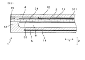
- FIG. 2 is a cross-sectional view taken along the line II-II of FIG.
- FIG. 3 is a development explanatory view of the gas sensor element according to the first embodiment.
- FIG. 4 is a cross-sectional explanatory view of the protruding angle portion in the first embodiment.
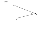
- FIG. 5 is an explanatory view of the angle ⁇ of the protruding angle portion in the first embodiment.
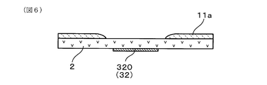
- FIG. 6 is an explanatory diagram of a method for manufacturing a gas sensor element according to the first embodiment, and is an explanatory diagram showing a state in which a ceramic paste is applied to a solid electrolyte body.
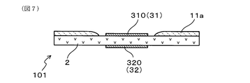
- FIG. 7 is an explanatory view of the first unfired body in the first embodiment.
- FIG. 8 is an explanatory view showing a state in which the ceramic paste is applied to the shielding layer in the first embodiment.
- FIG. 9 is an explanatory view of the second unfired body in the first embodiment.
- FIG. 10 is an explanatory view showing a state in which the first unfired body and the second unfired body are arranged to face each other in the first embodiment.
- FIG. 11 is an explanatory view of the third unfired body in the first embodiment.
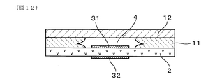
- FIG. 12 is an explanatory view showing a state after firing the third unfired body in the first embodiment.
- FIG. 13 is an enlarged cross-sectional photograph of the vicinity of the protruding angle portion in the first embodiment.
- FIG. 14 is a cross-sectional explanatory view of the gas sensor element in the comparative form.
- FIG. 15 is a schematic diagram illustrating thermal expansion of the gas sensor element when the temperature rises.
- FIG. 16 is a schematic view illustrating the warp of the gas sensor element.
- FIG. 17 is an explanatory diagram of the tensile stress acting on the vicinity of the protruding angle portion in the gas sensor element of the comparative form.
- FIG. 18 is an explanatory diagram of the tensile stress acting on the vicinity of the protruding angle portion in the gas sensor element of the first embodiment.
- FIG. 19 is a diagram showing the relationship between the angle ⁇ and the stress intensity factor.
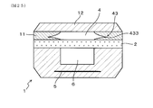
- FIG. 20 is a cross-sectional explanatory view of the gas sensor element according to the second embodiment, and is a cross-sectional view taken along the line XX-XX of FIG.
- FIG. 21 is a cross-sectional view taken along the line XXI-XXI of FIG.
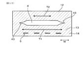
- FIG. 22 is a development explanatory view of the gas sensor element according to the second embodiment.
- FIG. 23 is a cross-sectional explanatory view of the gas sensor element not provided with the duct in the third embodiment.
- FIG. 24 is a cross-sectional explanatory view of the gas sensor element in which the duct is filled with the porous body in the third embodiment.
- FIG. 25 is a cross-sectional explanatory view of the gas sensor element provided with the heater in a planar shape in the third embodiment.
- FIG. 26 is a cross-sectional explanatory view of the gas sensor element in which the arrangement of the heater is changed in the third embodiment.
- FIG. 27 is a cross-sectional explanatory view of the gas sensor element in which the position of the chamber is changed in the third embodiment.
- FIG. 28 is a cross-sectional explanatory view of the chamber in the fourth embodiment in which the inner surface of the chamber cambium is a substantially flat surface.
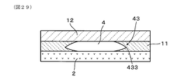
- FIG. 29 is a cross-sectional explanatory view of the chamber having a concave curved surface on the inner surface of the chamber cambium according to the fourth embodiment.
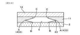
- FIG. 30 is a cross-sectional explanatory view of the chamber in which the chamber cambium has corners other than the vertices in the fourth embodiment.
- FIG. 31 is a cross-sectional explanatory view of another chamber in the fourth embodiment in which the chamber cambium has corners other than the vertices.
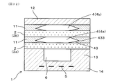
- FIG. 32 is a cross-sectional explanatory view of the gas sensor element according to the fifth embodiment.
- FIG. 33 is a cross-sectional explanatory view of a part of the gas sensor element in the sixth embodiment.
- FIG. 34 is a cross-sectional explanatory view of a part of the other gas sensor element in the sixth embodiment.
- FIG. 35 is a cross-sectional explanatory view of a part of the other gas sensor element in the sixth embodiment.
- FIG. 36 is a cross-sectional explanatory view of a part of the gas sensor element in the seventh embodiment.
- the gas sensor element 1 of the present embodiment is a laminated gas sensor element formed by laminating a plurality of ceramic layers.
- the gas sensor element 1 has a solid electrolyte body 2, a measurement electrode 31, a reference electrode 32, a chamber 4, and a heater 5.
- the solid electrolyte body 2 has oxygen ion conductivity.
- the measurement electrode 31 and the reference electrode 32 are provided on both main surfaces of the solid electrolyte body 2.
- the chamber 4 faces the measurement electrode 31 and is a space for introducing the gas to be measured.
- the heater 5 heats the solid electrolyte body 2.
- the chamber 4 has a protruding angle portion 43.
- the protruding angle portion 43 is a portion that protrudes in the width direction W in a cross section orthogonal to the longitudinal direction Y of the gas sensor element 1.
- the width direction W is a direction orthogonal to both the longitudinal direction Y and the stacking direction Z.
- the apex 433 of the protruding angle portion 43 is arranged closer to the heater 5 than the center 4C of the chamber 4 in the stacking direction Z.
- the gas sensor element 1 has an elongated shape, and a measurement electrode 31 and a reference electrode 32 are formed at positions close to one end in the longitudinal direction Y thereof.
- the side in the longitudinal direction Y where the measurement electrode 31 and the reference electrode 32 are provided is called the tip end side, and the opposite side is called the base end side.
- the apex 433 of the protruding angle portion 43 is arranged closer to the heater 5 than the center 4C of the chamber 4 in the stacking direction Z.
- the gas sensor element 1 of this embodiment has a duct 6.
- the duct 6 faces the reference electrode 32 and is a space into which the reference gas is introduced.
- the heater 5 is arranged on the opposite side of the solid electrolyte body 2 with the duct 6 sandwiched in the stacking direction Z.
- the chamber 4 has a larger dimension W in the width direction than the duct 6. Further, the width Wc of the chamber 4 and the width Wd of the duct 6 satisfy 1 ⁇ Wc / Wd ⁇ 1.73.
- the width Wc of the chamber 4 can be defined by the width dimension at the portion where the dimension of the width direction W is maximum. That is, the distance between the vertices 433 of the protruding angle portions 43 on both sides in the width direction W is the width Wc.
- the width Wd of the duct 6 can also be defined by the width dimension at the portion where the dimension of the width direction W is maximum. In the gas sensor element 1 shown in FIG. 1, the duct 6 has a maximum width at a portion facing the solid electrolyte body 2. In such a case, the width Wd of the duct 6 is defined by the width dimension of the portion facing the solid electrolyte body 2.
- the chamber forming layer 11 and the shielding layer 12 are sequentially laminated on the surface of the solid electrolyte body 2 on the side where the measurement electrode 31 is provided. Further, the duct forming layer 13 and the heater layer 14 are sequentially laminated on the surface of the solid electrolyte body 2 on the side where the reference electrode 32 is provided.
- the chamber forming layer 11 is a ceramic layer formed so as to surround the chamber 4 from a direction orthogonal to the stacking direction Z.
- the chamber 4 is formed between the chamber forming layer 11, the solid electrolyte body 2, and the shielding layer 12.
- a diffusion resistance portion 15 is provided in a part of the chamber cambium 11.
- the diffusion resistance portion 15 is a portion where the gas to be measured is introduced into the chamber 4 while being diffused.
- the chamber cambium 11 is drawn in two parts, which are shown corresponding to the individual ceramic pastes described later. Further, the two locations indicated by reference numerals 4 in the figure indicate locations where one chamber 4 is formed in a state where a plurality of ceramic layers are laminated.
- the diffusion resistance portion 15 is formed at the tip end portion of the gas sensor element 1. That is, the diffusion resistance portion 15 is arranged on the tip end side of the chamber 4.
- the diffusion resistance portion 15 is made of a porous ceramic.
- the gas sensor element 1 of the present embodiment is configured to introduce the gas to be measured into the chamber 4 from the tip end side of the element.
- the duct forming layer 13 is a ceramic layer formed so as to cover the duct 6 from the side opposite to the solid electrolyte body 2 and to surround the duct 6 from a direction orthogonal to the stacking direction Z. ..
- the duct forming layer 13 does not block the proximal end side of the duct 6. That is, the duct 6 is open to the base end portion of the gas sensor element 1.
- the reference gas is introduced into the duct 6 from the proximal end side of the gas sensor element 1.
- the reference gas is the atmosphere.
- the solid electrolyte body 2 is a ceramic layer containing zirconia as a main component.
- the chamber forming layer 11, the shielding layer 12, the duct forming layer 13, and the heater layer 14 are all ceramic layers containing alumina as a main component.
- the diffusion resistance portion 15 also contains alumina as a main component. However, it is made of a porous ceramic body so that the gas to be measured can permeate.
- the gas sensor element 1 is formed by laminating a plurality of ceramic layers, but in the finished product state, there may be no boundary between the ceramic layers.
- the boundary between the chamber forming layer 11 and the shielding layer 12 and the boundary between the duct forming layer 13 and the heater layer 14 may not exist.
- the width Wb of the chamber cambium 11 outside the chamber 4 is smaller than the width Wc of the chamber 4. Further, the width Wb of the chamber forming layer 11 is smaller than the width We of the duct forming layer 13 outside the duct 6.
- the protruding angle portions 43 of the chamber 4 are formed facing the same material on both sides in the stacking direction Z. That is, in this embodiment, the protruding angle portions 43 face materials having the same composition containing alumina as a main component on both sides in the stacking direction Z.
- the apex 433 of the protruding angle portion does not exist at the interface of different materials, but exists in the chamber cambium 11 made of the same material. Further, the portion of the chamber cambium 11 adjacent to the protruding angle portion 43 is substantially homogeneous.
- the chamber 4 has a first surface 41 and a second surface 42 facing the stacking direction Z.
- the first surface 41 is a surface on the side closer to the heater 5 in the stacking direction Z.
- the second surface 42 is a surface on the side far from the heater 5 in the stacking direction Z.
- the first surface 41 faces the solid electrolyte body 2.
- the second surface 42 faces the shielding layer 12.
- corner height t1 the dimension of the stacking direction Z between the first surface 41 and the apex 433 of the protruding angle portion 43
- the dimension of the stacking direction Z between the first surface 41 and the center 4C of the chamber 4 is referred to as "center height t2".
- the first surface 41 and the second surface 42 can have substantially the same width. However, the width of the first surface 41 can be made larger than the width of the second surface 42. Alternatively, the width of the first surface 41 can be made smaller than the width of the second surface 42.
- each protruding angle portion 43 is formed by two convex curved surfaces 431 and 432 that are curved surfaces that are convex toward the chamber 4.
- the convex curved surface 431 is a curved surface from the apex 433 of the protruding angle portion 43 to the first surface 41 in a cross section orthogonal to the longitudinal direction Y.
- the convex curved surface 432 is a curved surface from the apex 433 of the protruding angle portion 43 to the second surface 42 in a cross section orthogonal to the longitudinal direction Y.
- the angle ⁇ of at least a part of the protruding angle portions 43 is an acute angle, that is, less than 90 °. Further, the angle ⁇ of at least a part of the protruding angle portions 43 is 30 ° or less. In the present embodiment, the angle ⁇ is 30 ° or less at any of the protruding angle portions 43 at both ends in the width direction W.
- the angle ⁇ of the protruding angle portion 43 is defined as follows.
- the apex 433 of the protruding angle portion 43 is set as point A, one end of the first surface 41 on the protruding angle portion 43 side is designated as point B, and the second on the protruding angle portion 43 side.
- the angle CAB is the angle ⁇ as shown in FIG.
- the shapes of the protruding angle portions 43 formed on both sides of the chamber 4 in the width direction are substantially line-symmetrical with each other.
- the shape of the protruding angle portions 43 formed on both sides of the chamber 4 in the width direction may be asymmetrical with each other.
- the protruding angle portion 43 may be formed only on one side of the width direction W of the chamber 4.
- the ceramic paste 11a which is a part of the chamber forming layer 11, is applied to one surface of the unfired solid electrolyte body 2.
- the ceramic paste 11a is applied to a region of the surface of the solid electrolyte body 2 excluding the portion that becomes the first surface 41 of the chamber 4.
- FIG. 6 shows a state in which the conductive paste 320 serving as the reference electrode 32 is printed on the other surface of the solid electrolyte body 2 at this stage.
- the conductive paste 310 serving as the measurement electrode 31 is printed on the surface of the solid electrolyte body 2 on the side on which the ceramic paste 11a is applied. Further, the conductive paste 310 is continuously formed on a part of the surface of the ceramic paste 11a applied to the solid electrolyte body 2 (not shown). The conductive paste 310 in this portion becomes a lead 311 as shown in FIG. From the above, the first unfired body 101 is obtained.
- the ceramic paste 11b which is another part of the chamber forming layer 11, is applied to one surface of the unfired shielding layer 12.
- the ceramic paste 11b is applied to a region of the surface of the solid electrolyte body 2 excluding the portion that becomes the second surface 42 of the chamber 4.
- the burnt material 40 is applied so as to include the portion of the surface of the solid electrolyte body 2 that becomes the second surface 42 of the chamber 4.
- the burnt material 40 is applied so as to overlap a part of the ceramic paste 11b. From the above, the second unfired body 102 is obtained.
- the burnt material 40 can be, for example, a paste containing carbon powder.
- As the burnt-out material 40 a material that is burnt down in a subsequent firing step can be used.
- the first unfired body 101 and the second unfired body 102 are arranged so as to face each other so that the ceramic paste 11a and the ceramic paste 11b face each other. Then, in this posture, the first unfired body 101 and the second unfired body 102 are laminated and crimped to each other to obtain a third unfired body 103 as shown in FIG. In the third unfired body 103, the space serving as the chamber 4 is filled with the burnt material 40.
- the unfired duct forming layer 13 and the unfired heater layer 14 are laminated and pressure-bonded to the third unfired body 103 to be joined.
- a conductive paste serving as a heater 5 and a lead 51 connected to the heater 5 is printed on one surface of a ceramic sheet containing alumina as a main component (see FIG. 3).
- the third unfired body 103 is fired to obtain the gas sensor element 1.
- the burnt material 40 is burnt down and the chamber 4 is formed.
- the gas sensor element 1 as shown in FIGS. 1 and 2 can be obtained.
- FIG. 13 is a cross-sectional photograph of a part of the gas sensor element 1 actually manufactured. This cross-sectional photograph is generally a photograph of a portion corresponding to the cross section of the portion shown in FIG. In FIG. 13, the corner height t1 and the center height t2 are entered.
- the gas sensor element 1 of this embodiment can be, for example, a so-called A / F sensor element (that is, an air-fuel ratio sensor element) attached to the exhaust system of an automobile engine. Then, the air-fuel ratio can be detected by measuring the concentration of oxygen as a specific gas in the exhaust gas as the gas to be measured.
- a / F sensor element that is, an air-fuel ratio sensor element
- the apex 433 of the protruding angle portion 43 is arranged closer to the heater 5 than the center 4C of the chamber 4 in the stacking direction Z. Therefore, the tensile stress acting on the ceramic layer adjacent to the apex 433 of the protruding angle portion 43 can be suppressed due to the temperature difference generated during heating by the heater 5. As a result, element cracking can be effectively prevented.
- the gas sensor element 9 of the comparative embodiment shown in FIG. 14 has the gas sensor element 1 of the first embodiment in that the apex 433 of the protruding angle portion 43 of the chamber 4 is located on the side farther from the heater 5 than the center 4C of the chamber 4. Different from. Others are the same as the gas sensor element 1 of the first embodiment.
- the heater layer 14 and the duct forming layer 13 tend to have a higher temperature than the shielding layer 12.
- the expansion T1 of the heater layer 14 and the duct forming layer 13 in the width direction W is larger than the expansion T2 of the shielding layer 12 in the width direction W. It becomes.
- FIGS. 15 and 16 are schematic views, and ducts and the like are also omitted.
- cracks in the ceramic layer starting from the protruding angle portion 43 are more likely to occur as the tensile stress acting in the direction orthogonal to the protruding direction of the protruding angle portion 43 increases.
- the gas sensor element 9 of the comparative form shown in FIG. 17 and the gas sensor element 1 of the present form shown in FIG. 18 are compared.
- the vector component f of the thermal stress in the direction orthogonal to the projecting direction of the projecting angle portion 43 tends to be smaller in the vicinity of the projecting angle portion 43 than in the gas sensor element 9 of the comparative form. That is, the tensile stress f acting on the ceramic layer in the vicinity of the protruding angle portion 43 can be made smaller in this embodiment than in the comparative embodiment. Therefore, in the present embodiment, it is possible to suppress element cracking starting from the protruding angle portion 43.
- the angle ⁇ of at least a part of the protruding angle portions 43 is 30 ° or less.
- the angle ⁇ is 30 ° or less, cracks starting from the protruding angle portion 43 are relatively likely to occur unless the formation position of the apex 433 of the protruding angle portion 43 is appropriately set. That is, the following stress intensity factor K becomes large, and crack extension is likely to occur. Therefore, as described above, by arranging the position of the apex 433 of the protruding angle portion 43 closer to the heater 5 than the center 4C of the chamber 4, it is possible to prevent element cracking more effectively.
- a is the protruding length of the protruding angle portion 43.
- ⁇ is a stress generated at a position corresponding to the position of the protruding angle portion 43 in the chamber cambium 11 if the protruding angle portion 43 does not exist.
- the relationship between the angle ⁇ of the protruding angle portion 43 and the stress intensity factor K is shown in the graph of FIG.
- the stress intensity factor K is particularly large. That is, it can be seen that when ⁇ ⁇ 30 °, crack extension is particularly likely to occur, that is, element cracking is likely to occur.
- the chamber 4 has a larger dimension W in the width direction than the duct 6. As a result, it becomes easy to reduce the size of the gas sensor element 1 while securing the electrode reaction area of the measurement electrode 31.
- the width Wc of the chamber 4 increases, the width Wb of the chamber cambium 11 in the outer portion of the chamber 4 tends to decrease. As a result, the temperature of the shielding layer 12 is unlikely to rise, and a temperature difference in the stacking direction Z is likely to occur in the gas sensor element 1. Then, the thermal stress in the vicinity of the protruding angle portion 43 tends to increase.
- the heat of the heater 5 is easily transferred to the solid electrolyte body 2 inside the protruding angle portion 43 of the chamber 4 in the width direction W. Then, the solid electrolyte body 2 tends to expand inside the protruding angle portion 43, and the thermal stress in the vicinity of the protruding angle portion 43 tends to increase.
- the above-mentioned prevention of element cracking can be effectively realized by providing the position of the apex 433 of the protruding angle portion 43 at a position close to the heater 5.
- the protruding angle portions 43 are formed facing the same material on both sides in the stacking direction Z. Therefore, it is possible to suppress element cracking of the gas sensor element 1 starting from the apex 433 of the protruding angle portion 43.
- Example 1 In this example, as shown in Table 1, the effect of preventing element cracking and the measurement accuracy of gas sensor elements having various shapes were investigated. That is, a plurality of gas sensor elements having variously changed dimensions such as the width Wc of the chamber 4, the width Wd of the duct 6, the corner height t1, the center height t2, etc. were prepared as the samples 1 to 10.
- the heater 5 was energized to raise the temperature in each sample. That is, with each sample placed in the atmosphere, the heater 5 was energized with a constant applied voltage to raise the temperature. At this time, the core temperature of the heater 5 was raised from room temperature to 950 ° C. When the central temperature of the heater 5 reached 950 ° C., the energization of the heater was stopped and the heater 5 was naturally cooled. This operation was repeated 5 times. The central temperature of the heater 5 means the highest temperature portion of the heater 5. After performing this durability test, each sample was subjected to a dyeing appearance inspection to determine the presence or absence of element cracking.
- the temperature rise rate was changed by 50 ° C./sec, and the evaluation was made based on how much the temperature rise rate could be maintained without element cracking.
- the rate of temperature rise was the average rate of temperature rise from room temperature to 100 ° C.
- the results are shown in Table 1.
- the “allowable heating rate” in Table 1 indicates the maximum heating rate at which element cracking did not occur in this test. If the allowable temperature rise rate is 300 ° C./sec or more, there is no problem in terms of durability.
- the permissible temperature rise rate was 250 ° C./sec.
- the permissible temperature rise rate was 400 ° C./sec or more. That is, it was obtained that under the condition that the element cracking occurs in the sample 4 in which t> t2, the element cracking does not occur in any of the samples 1 to 3 satisfying t1 ⁇ t2.
- the description of " ⁇ 400" starts from at least the protruding angle portion 43 when the durability test is performed at the temperature rise rate of 400 ° C./sec. It indicates that no cracks have occurred, and includes the case where cracks have occurred in other parts.
- the term "element cracking” means element cracking starting from the protruding angle portion 43 unless otherwise specified.
- the permissible temperature rise rate of the sample 9 was 200 ° C./sec
- the permissible temperature rise rate of the sample 10 having the same Wb, Wc, and Wd as the sample 9 was 400 ° C./sec or more. there were. That is, it was obtained that the element cracking did not occur in the sample 10 satisfying t1 ⁇ t2 under the condition that the element cracking occurred in the sample 9 in which t> t2.
- Sample 5 In addition to Sample 4 and Sample 10, Sample 5, Sample 7, and Sample 8 satisfying t1 ⁇ t2 also had a high permissible temperature rise rate of 350 ° C./sec or more. This also confirms the effect of suppressing element cracking by providing the position of the apex 433 of the protruding angle portion 43 at a position closer to the heater 5 than the center 4C of the chamber 4.
- the measurement accuracy of the gas sensor element was evaluated with respect to the above sample.
- the measurement accuracy was evaluated by the accuracy of the value of the critical current detected when the exhaust gas of the gasoline engine in which the stoichiometric mixture was burned (hereinafter referred to as IL accuracy).
- the IL accuracy of Samples 1 to 4 and Samples 8 to 10 was within ⁇ 0.5%, which was good.
- the locations where the gas to be measured is introduced into the chamber 4 are provided on both sides of the chamber 4 in the width direction W.
- the diffusion resistance portion 15 is provided near the central portion of the chamber 4 in the longitudinal direction Y.
- the tip end side of the chamber 4 is closed by a part of the chamber cambium 11. That is, the chamber 4 is closed so that gas does not permeate on the tip side.
- the diffusion resistance portion 15 is formed in a part of the longitudinal direction Y of the chamber 4 along the second surface 42 of the chamber 4, as shown in FIGS. 20 and 21. Then, as shown in FIGS. 20 and 22, the diffusion resistance portion 15 is formed over the entire width direction W of the gas sensor element 1.
- the cross section of the gas sensor element 1 at the position where the diffusion resistance portion 15 exists appears in the shape as shown in FIG. At this time, On the other hand, the cross section of the gas sensor element 1 at the position where the diffusion resistance portion 15 does not exist is the same as the cross section of the gas sensor element 1 of the first embodiment shown in FIG.
- this embodiment is a variation of the structure of the ceramic layer on the side close to the heater 5 in the solid electrolyte body 2.
- the measurement electrode and the reference electrode are omitted. The same applies to FIGS. 28 to 35.
- the gas sensor element 1 shown in FIG. 23 is not provided with a duct.
- the duct 6 is filled with the porous body 60.
- the porous body 60 has a function of adsorbing and removing toxic substances that invade the duct 6 from the atmosphere side.
- the gas sensor element 1 shown in FIG. 25 has a heater 5 arranged in a plane.
- the heater 5 is arranged outside the duct 6 in the width direction. That is, the heater 5 is formed at a position where it does not overlap the duct 6 in the stacking direction Z.
- the gas sensor element 1 shown in FIG. 27 has a chamber 4 formed at a position between the heater 5 and the duct 6.
- the apex 433 of the protruding angle portion 43 of the chamber 4 is provided at a position in the stacking direction Z close to the heater 5, so that the element cracks. Can be suppressed.
- the same configuration and action / effect as in the first embodiment can be obtained.
- FIGS. 28 to 31 the shape and structure of the chamber 4 can be variously changed as shown in FIGS. 28 to 31, for example.
- a part of the structure of the gas sensor element 1 for example, the duct forming layer 13 and the heater layer 14 is omitted. The same applies to FIGS. 33 to 35 described later.
- the inner surface of the chamber cambium 11 forming the protruding angle portion 43 may be a substantially flat surface. As shown in FIG. 29, the inner surface of the chamber forming layer 11 forming the protruding angle portion 43 may be a concave curved surface.
- the inner surface of the chamber cambium 11 may have corners other than the apex 433 of the protruding corner 43.
- the angle ⁇ of the protruding angle portion 43 is set to the angle BAC with the vertices 433 of the protruding angle portion 43 as points A and the vertices of the corners adjacent to both sides in the stacking direction Z as points B and C, respectively.
- the angle ⁇ can be defined assuming that the vertices of the corners adjacent to both sides of the stacking direction Z with respect to the vertices 433 correspond to the points B and C shown in FIG. 5 above.
- this embodiment is a form of a gas sensor element 1 in which a plurality of chambers 4 are arranged in the stacking direction Z. Further, in this embodiment, two layers of the solid electrolyte body 2 are provided. Then, the chamber forming layer 11 is laminated on the surface of each solid electrolyte body 2a and 2b opposite to the heater 5. Chambers 4 (4a, 4b) are formed by these chamber forming layers 11, respectively.
- the apex 433 of the protruding angle portion 43 is arranged at a position closer to the heater 5 than the center 4C of the chamber 4.
- the apex 433 of the protruding angle portion 43 is arranged at a position closer to the heater 5 than the center 4C of the chamber 4.
- the apex 433 of the protruding angle portion 43 is arranged at a position closer to the heater 5 than the center 4C of the chamber 4.
- the gas sensor element 1 of this embodiment can be suitably used as, for example, a NOx sensor element for detecting a nitrogen oxide concentration.
- a pump cell is provided in the solid electrolyte body 2a on the side close to the heater 5, and a sensor cell is provided in the solid electrolyte body 2b on the side far from the heater 5.
- the gas to be measured (for example, exhaust gas) is introduced into the chamber 4a, and the reference gas (for example, the atmosphere) is introduced into the chamber 4b. While pumping oxygen in the chamber 4a to the duct 6 in the pump cell, the concentration of NOx (nitrogen oxide) in the gas to be measured is measured in the sensor cell.
- this embodiment is a modified form of the above-described second embodiment of a gas sensor element in which the formation position of the diffusion resistance portion 15 is variously changed.
- the diffusion resistance portion 15 can be configured to be interposed between the chamber forming layer 11 and the shielding layer 12.
- the diffusion resistance portion 15 can form the second surface 42 of the chamber 4.
- the diffusion resistance portion 15 may be formed over the entire longitudinal direction Y of the chamber 4.
- the diffusion resistance portion 15 may be provided only in a part of the chamber 4 in the longitudinal direction Y.
- the diffusion resistance portion 15 can be provided so as to cover the chamber 4 from the opposite side to the solid electrolyte body 2 without providing the shielding layer 12.
- the diffusion resistance portion 15 may be provided so as to be adjacent to the outside of the width direction W of the chamber 4. Further, in such a case, the apex 433 of the protruding angle portion 43 may be arranged at the interface between the diffusion resistance portion 15 and the chamber cambium 11. Others are the same as in the first embodiment. Also in this embodiment, the same effects as those in the first embodiment can be obtained.
- this embodiment is a form of a gas sensor element 1 having a two-cell structure in which a chamber 4 is provided between two solid electrolyte bodies 2.
- a reference cell is provided in the solid electrolyte body 2a on the side close to the heater 5, and a pump cell is provided in the solid electrolyte body 2b on the side far from the heater 5.
- the side of the pump cell opposite to the chamber 4 is exposed to the surface of the device via the porous layer 17.
- a diffusion resistance portion 15 is provided in a part of the chamber cambium 11. Further, no space is particularly provided on the side of the reference cell opposite to the chamber 4. That is, in this embodiment, the duct is not formed.
- the gas sensor element 1 having such a configuration applies a voltage between the electrodes of the pump cell so that the oxygen concentration in the chamber 4 is maintained at a predetermined value by the pump cell.
- an electromotive force is generated according to the oxygen concentration in the chamber 4.
- the pump cell is operated so that the electromotive force generated in the reference cell becomes constant. At this time, the oxygen concentration in the gas to be measured is measured based on the value of the current flowing through the pump cell.
- the apex 433 of the protruding angle portion 43 in the chamber 4 is arranged closer to the heater 5 than the center 4C of the chamber 4 in the stacking direction Z.
- Others are the same as in the first embodiment. Also in this embodiment, the same effects as those in the first embodiment can be obtained.
Landscapes
- Chemical & Material Sciences (AREA)
- Life Sciences & Earth Sciences (AREA)
- Health & Medical Sciences (AREA)
- Physics & Mathematics (AREA)
- Chemical Kinetics & Catalysis (AREA)
- Electrochemistry (AREA)
- Molecular Biology (AREA)
- Analytical Chemistry (AREA)
- Biochemistry (AREA)
- General Health & Medical Sciences (AREA)
- General Physics & Mathematics (AREA)
- Immunology (AREA)
- Pathology (AREA)
- Measuring Oxygen Concentration In Cells (AREA)
Priority Applications (3)
| Application Number | Priority Date | Filing Date | Title |
|---|---|---|---|
| DE112021000870.6T DE112021000870T5 (de) | 2020-02-05 | 2021-01-22 | Gassensorelement |
| CN202180012975.4A CN115053127B (zh) | 2020-02-05 | 2021-01-22 | 气体传感器元件 |
| US17/880,995 US12366549B2 (en) | 2020-02-05 | 2022-08-04 | Gas sensor element |
Applications Claiming Priority (2)
| Application Number | Priority Date | Filing Date | Title |
|---|---|---|---|
| JP2020-018041 | 2020-02-05 | ||
| JP2020018041A JP7215440B2 (ja) | 2020-02-05 | 2020-02-05 | ガスセンサ素子 |
Related Child Applications (1)
| Application Number | Title | Priority Date | Filing Date |
|---|---|---|---|
| US17/880,995 Continuation US12366549B2 (en) | 2020-02-05 | 2022-08-04 | Gas sensor element |
Publications (1)
| Publication Number | Publication Date |
|---|---|
| WO2021157378A1 true WO2021157378A1 (ja) | 2021-08-12 |
Family
ID=77199324
Family Applications (1)
| Application Number | Title | Priority Date | Filing Date |
|---|---|---|---|
| PCT/JP2021/002165 Ceased WO2021157378A1 (ja) | 2020-02-05 | 2021-01-22 | ガスセンサ素子 |
Country Status (5)
| Country | Link |
|---|---|
| US (1) | US12366549B2 (https=) |
| JP (1) | JP7215440B2 (https=) |
| CN (1) | CN115053127B (https=) |
| DE (1) | DE112021000870T5 (https=) |
| WO (1) | WO2021157378A1 (https=) |
Citations (10)
| Publication number | Priority date | Publication date | Assignee | Title |
|---|---|---|---|---|
| JP2000065782A (ja) * | 1998-08-25 | 2000-03-03 | Denso Corp | 積層型空燃比センサ素子 |
| US20040140213A1 (en) * | 2002-11-13 | 2004-07-22 | Johannes Kanters | Gas sensor |
| JP2006030165A (ja) * | 2004-06-14 | 2006-02-02 | Denso Corp | ガスセンサ素子 |
| US20060151466A1 (en) * | 2004-12-15 | 2006-07-13 | Lothar Diehl | Sensor element for determining gas components in gas mixtures, and method for manufacturing it |
| JP2007248219A (ja) * | 2006-03-15 | 2007-09-27 | Denso Corp | セラミック積層体及びその製造方法 |
| JP2009250655A (ja) * | 2008-04-02 | 2009-10-29 | Denso Corp | ガスセンサ素子 |
| JP2010261727A (ja) * | 2009-04-30 | 2010-11-18 | Denso Corp | ガスセンサ素子及びその製造方法、並びにガスセンサ |
| JP2012247390A (ja) * | 2011-05-31 | 2012-12-13 | Denso Corp | ガスセンサ素子及びその製造方法、並びにガスセンサ |
| JP2015007610A (ja) * | 2013-05-28 | 2015-01-15 | 日本特殊陶業株式会社 | ガスセンサ素子およびガスセンサ |
| JP2018185234A (ja) * | 2017-04-26 | 2018-11-22 | 株式会社デンソー | ガスセンサ |
Family Cites Families (7)
| Publication number | Priority date | Publication date | Assignee | Title |
|---|---|---|---|---|
| JP3832437B2 (ja) * | 2002-04-03 | 2006-10-11 | 株式会社デンソー | ガスセンサ素子 |
| JP5287795B2 (ja) * | 2010-05-28 | 2013-09-11 | 株式会社デンソー | ガスセンサ |
| JP6367709B2 (ja) * | 2014-12-26 | 2018-08-01 | 日本特殊陶業株式会社 | ガスセンサ素子およびガスセンサ |
| DE102015226644A1 (de) * | 2015-12-23 | 2017-06-29 | Robert Bosch Gmbh | Sensorelement zur Erfassung mindestens einer Eigenschaft eines Messgases in einem Messgasraum |
| JP6804367B2 (ja) * | 2017-03-30 | 2020-12-23 | 日本碍子株式会社 | センサ素子及びガスセンサ |
| JP6932666B2 (ja) * | 2018-03-16 | 2021-09-08 | 日本碍子株式会社 | ガスセンサ |
| JP2020018041A (ja) | 2018-07-23 | 2020-01-30 | 株式会社Soken | 空調装置 |
-
2020
- 2020-02-05 JP JP2020018041A patent/JP7215440B2/ja active Active
-
2021
- 2021-01-22 CN CN202180012975.4A patent/CN115053127B/zh active Active
- 2021-01-22 DE DE112021000870.6T patent/DE112021000870T5/de active Pending
- 2021-01-22 WO PCT/JP2021/002165 patent/WO2021157378A1/ja not_active Ceased
-
2022
- 2022-08-04 US US17/880,995 patent/US12366549B2/en active Active
Patent Citations (10)
| Publication number | Priority date | Publication date | Assignee | Title |
|---|---|---|---|---|
| JP2000065782A (ja) * | 1998-08-25 | 2000-03-03 | Denso Corp | 積層型空燃比センサ素子 |
| US20040140213A1 (en) * | 2002-11-13 | 2004-07-22 | Johannes Kanters | Gas sensor |
| JP2006030165A (ja) * | 2004-06-14 | 2006-02-02 | Denso Corp | ガスセンサ素子 |
| US20060151466A1 (en) * | 2004-12-15 | 2006-07-13 | Lothar Diehl | Sensor element for determining gas components in gas mixtures, and method for manufacturing it |
| JP2007248219A (ja) * | 2006-03-15 | 2007-09-27 | Denso Corp | セラミック積層体及びその製造方法 |
| JP2009250655A (ja) * | 2008-04-02 | 2009-10-29 | Denso Corp | ガスセンサ素子 |
| JP2010261727A (ja) * | 2009-04-30 | 2010-11-18 | Denso Corp | ガスセンサ素子及びその製造方法、並びにガスセンサ |
| JP2012247390A (ja) * | 2011-05-31 | 2012-12-13 | Denso Corp | ガスセンサ素子及びその製造方法、並びにガスセンサ |
| JP2015007610A (ja) * | 2013-05-28 | 2015-01-15 | 日本特殊陶業株式会社 | ガスセンサ素子およびガスセンサ |
| JP2018185234A (ja) * | 2017-04-26 | 2018-11-22 | 株式会社デンソー | ガスセンサ |
Also Published As
| Publication number | Publication date |
|---|---|
| JP2021124389A (ja) | 2021-08-30 |
| CN115053127B (zh) | 2024-07-30 |
| CN115053127A (zh) | 2022-09-13 |
| US20220373504A1 (en) | 2022-11-24 |
| DE112021000870T5 (de) | 2022-11-17 |
| US12366549B2 (en) | 2025-07-22 |
| JP7215440B2 (ja) | 2023-01-31 |
Similar Documents
| Publication | Publication Date | Title |
|---|---|---|
| JP4172279B2 (ja) | ガスセンサ | |
| JP2019158554A (ja) | センサ素子及びガスセンサ | |
| JP7227824B2 (ja) | ガスセンサのセンサ素子 | |
| JP5158009B2 (ja) | ガスセンサ素子及びその製造方法、並びにガスセンサ | |
| JP5835092B2 (ja) | ガスセンサ素子 | |
| JP4093784B2 (ja) | 積層型ガスセンサ素子及びその製造方法並びにガスセンサ | |
| WO2021157378A1 (ja) | ガスセンサ素子 | |
| EP2490015B1 (en) | Method of manufacturing a gas sensor element | |
| JP4228975B2 (ja) | 積層型ガスセンサ素子 | |
| CN108693233B (zh) | 传感器元件 | |
| US20090000352A1 (en) | Gas sensing element with increased mechanical strength | |
| US11209387B2 (en) | Gas sensor element and gas sensor | |
| Neumann et al. | Advanced planar oxygen sensors for future emission control strategies | |
| JP3860768B2 (ja) | 酸素センサ素子 | |
| JP4061125B2 (ja) | 酸素センサ素子の製造方法 | |
| JP7360311B2 (ja) | ガスセンサのセンサ素子 | |
| JP5035078B2 (ja) | ガスセンサ素子 | |
| WO2020203027A1 (ja) | ガスセンサのセンサ素子 | |
| JP5024238B2 (ja) | ガスセンサ素子の製造方法 | |
| JP2005300472A (ja) | 積層型ガスセンサ素子 | |
| JP2008157649A (ja) | 積層型ガスセンサ | |
| JP4579636B2 (ja) | ガスセンサの製造方法 | |
| JP2023148572A (ja) | センサ素子及びガスセンサ | |
| JP2003149196A (ja) | 酸素センサ | |
| JP2023033155A (ja) | センサ素子及びガスセンサ |
Legal Events
| Date | Code | Title | Description |
|---|---|---|---|
| 121 | Ep: the epo has been informed by wipo that ep was designated in this application |
Ref document number: 21751472 Country of ref document: EP Kind code of ref document: A1 |
|
| 122 | Ep: pct application non-entry in european phase |
Ref document number: 21751472 Country of ref document: EP Kind code of ref document: A1 |