WO2020179216A1 - モータユニット - Google Patents
モータユニット Download PDFInfo
- Publication number
- WO2020179216A1 WO2020179216A1 PCT/JP2020/000652 JP2020000652W WO2020179216A1 WO 2020179216 A1 WO2020179216 A1 WO 2020179216A1 JP 2020000652 W JP2020000652 W JP 2020000652W WO 2020179216 A1 WO2020179216 A1 WO 2020179216A1
- Authority
- WO
- WIPO (PCT)
- Prior art keywords
- motor
- housing
- supply pipe
- oil
- gear
- Prior art date
- Legal status (The legal status is an assumption and is not a legal conclusion. Google has not performed a legal analysis and makes no representation as to the accuracy of the status listed.)
- Ceased
Links
Images

Classifications
-
- H—ELECTRICITY
- H02—GENERATION; CONVERSION OR DISTRIBUTION OF ELECTRIC POWER
- H02K—DYNAMO-ELECTRIC MACHINES
- H02K7/00—Arrangements for handling mechanical energy structurally associated with dynamo-electric machines, e.g. structural association with mechanical driving motors or auxiliary dynamo-electric machines
- H02K7/10—Structural association with clutches, brakes, gears, pulleys or mechanical starters
- H02K7/116—Structural association with clutches, brakes, gears, pulleys or mechanical starters with gears
-
- H—ELECTRICITY
- H02—GENERATION; CONVERSION OR DISTRIBUTION OF ELECTRIC POWER
- H02K—DYNAMO-ELECTRIC MACHINES
- H02K5/00—Casings; Enclosures; Supports
- H02K5/04—Casings or enclosures characterised by the shape, form or construction thereof
- H02K5/22—Auxiliary parts of casings not covered by groups H02K5/06-H02K5/20, e.g. shaped to form connection boxes or terminal boxes
-
- B—PERFORMING OPERATIONS; TRANSPORTING
- B60—VEHICLES IN GENERAL
- B60K—ARRANGEMENT OR MOUNTING OF PROPULSION UNITS OR OF TRANSMISSIONS IN VEHICLES; ARRANGEMENT OR MOUNTING OF PLURAL DIVERSE PRIME-MOVERS IN VEHICLES; AUXILIARY DRIVES FOR VEHICLES; INSTRUMENTATION OR DASHBOARDS FOR VEHICLES; ARRANGEMENTS IN CONNECTION WITH COOLING, AIR INTAKE, GAS EXHAUST OR FUEL SUPPLY OF PROPULSION UNITS IN VEHICLES
- B60K17/00—Arrangement or mounting of transmissions in vehicles
- B60K17/04—Arrangement or mounting of transmissions in vehicles characterised by arrangement, location or kind of gearing
-
- B—PERFORMING OPERATIONS; TRANSPORTING
- B60—VEHICLES IN GENERAL
- B60L—PROPULSION OF ELECTRICALLY-PROPELLED VEHICLES; SUPPLYING ELECTRIC POWER FOR AUXILIARY EQUIPMENT OF ELECTRICALLY-PROPELLED VEHICLES; ELECTRODYNAMIC BRAKE SYSTEMS FOR VEHICLES IN GENERAL; MAGNETIC SUSPENSION OR LEVITATION FOR VEHICLES; MONITORING OPERATING VARIABLES OF ELECTRICALLY-PROPELLED VEHICLES; ELECTRIC SAFETY DEVICES FOR ELECTRICALLY-PROPELLED VEHICLES
- B60L50/00—Electric propulsion with power supplied within the vehicle
- B60L50/50—Electric propulsion with power supplied within the vehicle using propulsion power supplied by batteries or fuel cells
- B60L50/51—Electric propulsion with power supplied within the vehicle using propulsion power supplied by batteries or fuel cells characterised by AC-motors
-
- H—ELECTRICITY
- H02—GENERATION; CONVERSION OR DISTRIBUTION OF ELECTRIC POWER
- H02K—DYNAMO-ELECTRIC MACHINES
- H02K1/00—Details of the magnetic circuit
- H02K1/06—Details of the magnetic circuit characterised by the shape, form or construction
- H02K1/22—Rotating parts of the magnetic circuit
- H02K1/32—Rotating parts of the magnetic circuit with channels or ducts for flow of cooling medium
-
- H—ELECTRICITY
- H02—GENERATION; CONVERSION OR DISTRIBUTION OF ELECTRIC POWER
- H02K—DYNAMO-ELECTRIC MACHINES
- H02K11/00—Structural association of dynamo-electric machines with electric components or with devices for shielding, monitoring or protection
- H02K11/30—Structural association with control circuits or drive circuits
- H02K11/33—Drive circuits, e.g. power electronics
-
- H—ELECTRICITY
- H02—GENERATION; CONVERSION OR DISTRIBUTION OF ELECTRIC POWER
- H02K—DYNAMO-ELECTRIC MACHINES
- H02K5/00—Casings; Enclosures; Supports
- H02K5/04—Casings or enclosures characterised by the shape, form or construction thereof
- H02K5/20—Casings or enclosures characterised by the shape, form or construction thereof with channels or ducts for flow of cooling medium
- H02K5/203—Casings or enclosures characterised by the shape, form or construction thereof with channels or ducts for flow of cooling medium specially adapted for liquids, e.g. cooling jackets
-
- H—ELECTRICITY
- H02—GENERATION; CONVERSION OR DISTRIBUTION OF ELECTRIC POWER
- H02K—DYNAMO-ELECTRIC MACHINES
- H02K5/00—Casings; Enclosures; Supports
- H02K5/04—Casings or enclosures characterised by the shape, form or construction thereof
- H02K5/22—Auxiliary parts of casings not covered by groups H02K5/06-H02K5/20, e.g. shaped to form connection boxes or terminal boxes
- H02K5/225—Terminal boxes or connection arrangements
-
- H—ELECTRICITY
- H02—GENERATION; CONVERSION OR DISTRIBUTION OF ELECTRIC POWER
- H02K—DYNAMO-ELECTRIC MACHINES
- H02K9/00—Arrangements for cooling or ventilating
- H02K9/19—Arrangements for cooling or ventilating for machines with closed casing and closed-circuit cooling using a liquid cooling medium, e.g. oil
- H02K9/193—Arrangements for cooling or ventilating for machines with closed casing and closed-circuit cooling using a liquid cooling medium, e.g. oil with provision for replenishing the cooling medium; with means for preventing leakage of the cooling medium
-
- H—ELECTRICITY
- H02—GENERATION; CONVERSION OR DISTRIBUTION OF ELECTRIC POWER
- H02M—APPARATUS FOR CONVERSION BETWEEN AC AND AC, BETWEEN AC AND DC, OR BETWEEN DC AND DC, AND FOR USE WITH MAINS OR SIMILAR POWER SUPPLY SYSTEMS; CONVERSION OF DC OR AC INPUT POWER INTO SURGE OUTPUT POWER; CONTROL OR REGULATION THEREOF
- H02M7/00—Conversion of AC power input into DC power output; Conversion of DC power input into AC power output
- H02M7/42—Conversion of DC power input into AC power output without possibility of reversal
- H02M7/44—Conversion of DC power input into AC power output without possibility of reversal by static converters
- H02M7/48—Conversion of DC power input into AC power output without possibility of reversal by static converters using discharge tubes with control electrode or semiconductor devices with control electrode
-
- B—PERFORMING OPERATIONS; TRANSPORTING
- B60—VEHICLES IN GENERAL
- B60L—PROPULSION OF ELECTRICALLY-PROPELLED VEHICLES; SUPPLYING ELECTRIC POWER FOR AUXILIARY EQUIPMENT OF ELECTRICALLY-PROPELLED VEHICLES; ELECTRODYNAMIC BRAKE SYSTEMS FOR VEHICLES IN GENERAL; MAGNETIC SUSPENSION OR LEVITATION FOR VEHICLES; MONITORING OPERATING VARIABLES OF ELECTRICALLY-PROPELLED VEHICLES; ELECTRIC SAFETY DEVICES FOR ELECTRICALLY-PROPELLED VEHICLES
- B60L2220/00—Electrical machine types; Structures or applications thereof
- B60L2220/10—Electrical machine types
- B60L2220/14—Synchronous machines
-
- B—PERFORMING OPERATIONS; TRANSPORTING
- B60—VEHICLES IN GENERAL
- B60L—PROPULSION OF ELECTRICALLY-PROPELLED VEHICLES; SUPPLYING ELECTRIC POWER FOR AUXILIARY EQUIPMENT OF ELECTRICALLY-PROPELLED VEHICLES; ELECTRODYNAMIC BRAKE SYSTEMS FOR VEHICLES IN GENERAL; MAGNETIC SUSPENSION OR LEVITATION FOR VEHICLES; MONITORING OPERATING VARIABLES OF ELECTRICALLY-PROPELLED VEHICLES; ELECTRIC SAFETY DEVICES FOR ELECTRICALLY-PROPELLED VEHICLES
- B60L2240/00—Control parameters of input or output; Target parameters
- B60L2240/40—Drive Train control parameters
- B60L2240/42—Drive Train control parameters related to electric machines
- B60L2240/425—Temperature
-
- B—PERFORMING OPERATIONS; TRANSPORTING
- B60—VEHICLES IN GENERAL
- B60L—PROPULSION OF ELECTRICALLY-PROPELLED VEHICLES; SUPPLYING ELECTRIC POWER FOR AUXILIARY EQUIPMENT OF ELECTRICALLY-PROPELLED VEHICLES; ELECTRODYNAMIC BRAKE SYSTEMS FOR VEHICLES IN GENERAL; MAGNETIC SUSPENSION OR LEVITATION FOR VEHICLES; MONITORING OPERATING VARIABLES OF ELECTRICALLY-PROPELLED VEHICLES; ELECTRIC SAFETY DEVICES FOR ELECTRICALLY-PROPELLED VEHICLES
- B60L2240/00—Control parameters of input or output; Target parameters
- B60L2240/40—Drive Train control parameters
- B60L2240/52—Drive Train control parameters related to converters
- B60L2240/525—Temperature of converter or components thereof
-
- H—ELECTRICITY
- H02—GENERATION; CONVERSION OR DISTRIBUTION OF ELECTRIC POWER
- H02K—DYNAMO-ELECTRIC MACHINES
- H02K2205/00—Specific aspects not provided for in the other groups of this subclass relating to casings, enclosures, supports
- H02K2205/09—Machines characterised by drain passages or by venting, breathing or pressure compensating means
-
- Y—GENERAL TAGGING OF NEW TECHNOLOGICAL DEVELOPMENTS; GENERAL TAGGING OF CROSS-SECTIONAL TECHNOLOGIES SPANNING OVER SEVERAL SECTIONS OF THE IPC; TECHNICAL SUBJECTS COVERED BY FORMER USPC CROSS-REFERENCE ART COLLECTIONS [XRACs] AND DIGESTS
- Y02—TECHNOLOGIES OR APPLICATIONS FOR MITIGATION OR ADAPTATION AGAINST CLIMATE CHANGE
- Y02T—CLIMATE CHANGE MITIGATION TECHNOLOGIES RELATED TO TRANSPORTATION
- Y02T10/00—Road transport of goods or passengers
- Y02T10/60—Other road transportation technologies with climate change mitigation effect
- Y02T10/70—Energy storage systems for electromobility, e.g. batteries
Definitions
- the present invention relates to a motor unit.
- This application applies to Japanese Patent Application No. 2019-040863 filed in Japan on March 6, 2019, Japanese Patent Application No. 2019-075237 filed in Japan on April 11, 2019, and to Japan on June 13, 2019.
- Priority is claimed based on the filed Japanese Patent Application No. 2019-110648, the contents of which are incorporated herein.
- Patent Document 1 discloses a motor case in which a communication passage connected to the motor chamber is provided in a path connecting the gear chamber to the breather mechanism. According to this configuration, it is possible to prevent the hydraulic oil from leaking from the breather device.
- a motor unit of the present invention is a motor having a rotor that rotates about a motor axis and a stator that is positioned radially outside the rotor, a housing having a motor housing portion that houses the motor, and the housing. It is provided with a refrigerant path for circulating the refrigerant through the inside.
- the core back portion of the stator has a plurality of fixing portions that protrude radially outward from the outer peripheral surface, extend along the axial direction, and are fixed to the housing.
- the plurality of fixing portions include an upper fixing portion protruding upward from the outer peripheral surface of the core back portion.
- the coolant path has a supply unit that supplies the coolant to the outer peripheral surface of the core back unit.
- the supply unit is located on a circumferential side portion of the upper fixing unit.
- the housing is provided with a breather portion which is located above the upper fixing portion and which communicates the inside of the motor housing portion with the outside of the housing.
- the motor unit of one aspect of the present invention it is possible to provide a motor unit capable of suppressing the leakage of oil from the breather portion.
- FIG. 1 is a conceptual configuration diagram schematically showing a motor unit of one embodiment.
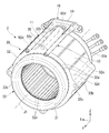
- FIG. 2 is a perspective view showing the stator and the supply pipe unit of one embodiment.
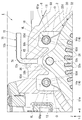
- FIG. 3 is a partial cross-sectional view of the motor unit 1 according to the embodiment.
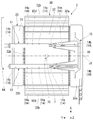
- FIG. 4 is a top view showing the stator and the supply pipe unit of one embodiment.
- the vertical direction will be defined based on the positional relationship when the motor unit 1 of the present embodiment is mounted on a vehicle (not shown) located on a horizontal road surface.
- the XYZ coordinate system is shown as a three-dimensional Cartesian coordinate system as appropriate.
- the Z-axis direction is the vertical direction.
- the + Z side is the upper side in the vertical direction
- the ⁇ Z side is the lower side in the vertical direction.
- the upper side in the vertical direction is simply referred to as "upper side”
- the lower side in the vertical direction is simply referred to as "lower side”.
- the X-axis direction is a direction orthogonal to the Z-axis direction, and is the front-back direction of the vehicle in which the motor unit 1 is mounted.
- the + X side is the front side of the vehicle
- the ⁇ X side is the rear side of the vehicle.
- the Y-axis direction is a direction orthogonal to both the X-axis direction and the Z-axis direction, and is the vehicle left-right direction, that is, the vehicle width direction.
- the + Y side is the left side of the vehicle
- the ⁇ Y side is the right side of the vehicle.
- the Y-axis direction corresponds to the axial direction of the motor axis J1 described later.
- the front-back direction and the left-right direction are horizontal directions orthogonal to the vertical direction.
- the left side corresponds to one side in the axial direction
- the right side corresponds to the other side in the axial direction.
- the front side corresponds to one side in the horizontal direction
- the rear side corresponds to the other side in the horizontal direction.
- the positional relationship in the front-rear direction is not limited to the positional relationship of the present embodiment, and the + X side may be the rear side of the vehicle and the ⁇ X side may be the front side of the vehicle.
- the + Y side is the right side of the vehicle, and the ⁇ Y side is the left side of the vehicle.
- the motor axis J1 shown in each figure extends in the Y-axis direction, that is, in the left-right direction of the vehicle.
- a direction parallel to the motor axis J1 is simply referred to as “axial direction”
- a radial direction around the motor axis J1 is simply referred to as “radial direction”
- the motor axis J1 is centered.
- the circumferential direction, that is, the circumference of the motor axis J1 is simply referred to as the "circumferential direction”.
- the one axial side (+Y side) is the axial direction from the motor housing portion 61 of the housing 6 to the gear housing portion 62, which will be described later.
- the other side ( ⁇ Y side) in the axial direction is the direction from the gear accommodating portion 62 to the motor accommodating portion 61 in the axial direction.
- the “parallel direction” includes a substantially parallel direction
- the “orthogonal direction” includes a substantially orthogonal direction.
- FIG. 1 is a conceptual diagram schematically showing the motor unit 1.
- the motor unit 1 of the present embodiment is mounted on a vehicle having a motor as a power source, such as a hybrid vehicle (HEV), a plug-in hybrid vehicle (PHV), and an electric vehicle (EV), and is used as a power source thereof.
- a vehicle having a motor as a power source such as a hybrid vehicle (HEV), a plug-in hybrid vehicle (PHV), and an electric vehicle (EV), and is used as a power source thereof.
- HEV hybrid vehicle
- HEV electric vehicle
- the motor unit 1 includes a motor 2, a gear unit 3 including a speed reducer 4 and a differential device 5, a housing 6, and an oil passage (refrigerant passage) 90.
- the oil passage 90 includes a pump 96, a cooler 97, a first supply pipe (supply unit) 11, and a second supply pipe (supply unit) 12.
- the first supply pipe 11 and the second supply pipe 12 form a part of the supply pipe unit 10.
- the housing 6 includes a motor accommodating portion 61 that accommodates the motor 2, a gear accommodating portion 62 that accommodates the gear portion 3, and a partition wall 61c that axially partitions the interior of the motor accommodating portion 61 from the gear accommodating portion 62. , And a breather unit 70.
- the gear accommodating portion 62 is located on the left side (+Y side) of the motor accommodating portion 61.
- the bottom portion 61s of the motor accommodating portion 61 is located above the bottom portion 62a of the gear accommodating portion 62.
- the partition wall 61c is provided with a partition wall opening 68.
- the partition opening 68 connects the inside of the motor housing 61 and the inside of the gear housing 62.
- the partition wall 61c is located on the left side of the stator 30.
- Oil O as a refrigerant is accommodated inside the housing 6.
- the refrigerant is oil O.
- oil (refrigerant) O is housed inside the motor housing portion 61 and inside the gear housing portion 62.
- An oil sump P for accumulating oil O is provided in a lower region inside the gear accommodating portion 62.
- the oil O in the oil sump P is sent to the inside of the motor accommodating portion 61 by the oil passage 90.
- the oil O sent to the inside of the motor housing portion 61 collects in the lower region inside the motor housing portion 61. At least a part of the oil O accumulated inside the motor accommodating portion 61 moves to the gear accommodating portion 62 through the partition wall opening 68 and returns to the oil sump P.
- Oil O circulates in an oil passage 90 described later.
- the oil O functions not only for cooling the motor 2 but also for lubricating the gear portion 3.
- Oil O is a lubricating oil for automatic transmissions (ATF: Automatic) with a relatively low viscosity in order to perform the functions of a lubricating oil and a cooling oil. It is preferable to use an oil equivalent to Transmission Fluid).
- the motor 2 is an inner rotor type motor.
- the motor 2 includes a rotor 20, a stator 30, and a plurality of bearings 26 and 27.
- the rotor 20 can rotate about the motor axis J1 extending in the horizontal direction.
- the rotor 20 has a shaft 21 and a rotor body 24.
- the rotor body 24 has a rotor core and a rotor magnet fixed to the rotor core. The torque of the rotor 20 is transmitted to the gear portion 3.
- the shaft 21 extends along the axial direction about the motor axis J1.
- the shaft 21 rotates about the motor axis J1.
- the shaft 21 is a hollow shaft provided with a hollow portion 22 inside.
- the shaft 21 is provided with a communication hole 23.
- the communication hole 23 extends in the radial direction and connects the hollow portion 22 and the outside of the shaft 21.
- the shaft 21 extends across the motor housing portion 61 and the gear housing portion 62 of the housing 6. The left end of the shaft 21 projects into the gear accommodating portion 62. A first gear 41, which will be described later, of the gear unit 3 is fixed to the left end of the shaft 21.
- the shaft 21 is rotatably supported by bearings 26 and 27.
- the stator 30 faces the rotor 20 with a gap in the radial direction.
- the stator 30 is located radially outside the rotor 20.
- the outer peripheral surface of the stator 30 faces the inner peripheral surface of the housing 6.
- the stator 30 has a stator core 32 and a coil assembly 33.
- the stator core 32 is fixed to the inner surface of the motor housing portion 61.
- FIG. 2 is a perspective view showing the stator 30 and the supply pipe unit 10 located above the stator 30.
- the stator core 32 has a cylindrical core back portion 32d extending in the axial direction, and a plurality of tooth portions 32e extending radially inward from the core back portion 32d.
- the plurality of tooth portions 32e are arranged at intervals in the circumferential direction.
- the plurality of tooth portions 32e are arranged at equal intervals over the entire circumference in the circumferential direction.
- the core back portion 32d has a plurality of fixing portions 32b protruding outward in the radial direction from the outer peripheral surface.
- the fixing portion 32b is fixed to the inner surface of the motor housing portion 61. That is, the stator 30 is fixed to the housing 6 at the fixing portion 32b.
- a plurality of fixed portions 32b are provided at intervals in the circumferential direction. For example, four fixing portions 32b are provided. The four fixing portions 32b are arranged at equal intervals over the entire circumference in the circumferential direction.
- the fixed portion 32b extends along the axial direction.
- the fixing portion 32b extends from the left (+Y side) end of the stator core 32 to the right ( ⁇ Y side) end of the stator core 32. That is, the fixed portion 32b extends over the entire axial length of the stator core 32.
- the fixing portion 32b has a through hole 32c that penetrates the fixing portion 32b in the axial direction.
- a bolt (not shown) extending in the axial direction is passed through the through hole 32c.
- the bolt is passed through the through hole 32c from the right side ( ⁇ Y side) and is tightened in a female screw hole (not shown) provided on the inner side surface of the motor housing portion 61. By tightening the bolt into the female screw hole, the fixing portion 32b is fixed to the motor accommodating portion 61.
- one of the plurality (four in this embodiment) of fixing portions 32b that protrudes upward from the outer peripheral surface of the core back portion 32d is referred to as an upper fixing portion 35. That is, one of the plurality of fixing portions 32b includes the upper fixing portion 35.
- the other fixing portions 32b project downward, forward (+ X side), and rearward ( ⁇ X side), respectively.
- the coil assembly 33 has a plurality of coils 31 attached to the stator core 32.
- the plurality of coils 31 are attached to the teeth 32e of the stator core 32 via an insulator (not shown).
- the plurality of coils 31 are arranged side by side in the circumferential direction.
- the plurality of coils 31 are arranged at equal intervals over the entire circumference in the circumferential direction.
- the coil assembly 33 may have a binding member that binds the coils 31 or the like, or may have a connecting wire that connects the coils 31 to each other.
- the coil assembly 33 has a pair of coil ends 33a and 33b projecting from the stator core 32 in the axial direction.
- the coil end 33a is a portion of the coil assembly 33 that protrudes from the stator core 32 to the right ( ⁇ Y side).
- the coil end 33b is a part of the coil assembly 33 that protrudes leftward (+Y side) from the stator core 32.
- the coil end 33a includes a portion of each coil 31 included in the coil assembly 33 that projects to the right of the stator core 32.
- the coil end 33b includes a portion of each coil 31 included in the coil assembly 33 that protrudes to the left side of the stator core 32.
- the coil ends 33a and 33b are annular with the motor axis J1 as the center.
- the coil ends 33a and 33b may include a binding member or the like that binds the coils 31, or may include a crossover connecting the coils 31 to each other.
- the bearings 26 and 27 rotatably support the rotor 20.
- the bearings 26 and 27 are, for example, ball bearings.
- the bearing 26 is a bearing that rotatably supports a portion of the rotor 20 located on the right side of the stator core 32.
- the bearing 26 supports a portion of the shaft 21 located on the right side of the portion to which the rotor body 24 is fixed.
- the bearing 26 is held by a wall portion 61b of the motor accommodating portion 61 that covers the right side of the rotor 20 and the stator 30.
- the wall portion 61b constitutes a part of the wall portion of the housing 6, and closes the opening on the right side of the motor housing portion 61.
- the bearing 27 is a bearing that rotatably supports a portion of the rotor 20 located on the left side of the stator core 32.
- the bearing 27 supports the portion of the shaft 21 located on the left side of the portion to which the rotor body 24 is fixed.
- the bearing 27 is held by the partition wall 61c.
- the gear unit 3 is housed in the gear housing unit 62 of the housing 6.
- the gear unit 3 is connected to the motor 2. More specifically, the gear portion 3 is connected to the left end of the shaft 21.
- the gear portion 3 includes a speed reducing device 4 and a differential device 5. The torque output from the motor 2 is transmitted to the differential device 5 via the speed reducer 4.
- the speed reducer 4 is connected to the motor 2.
- the speed reduction device 4 reduces the rotation speed of the motor 2 and increases the torque output from the motor 2 according to the reduction ratio.
- the speed reducing device 4 transmits the torque output from the motor 2 to the differential device 5.
- the reduction gear device 4 includes a first gear 41, a second gear 42, a third gear 43, and an intermediate shaft 45.
- the first gear 41 is fixed to the outer peripheral surface of the left end of the shaft 21.
- the first gear 41 rotates around the motor axis J1 together with the shaft 21.
- the intermediate shaft 45 extends along an intermediate axis J2 parallel to the motor axis J1.
- the intermediate shaft 45 rotates about the intermediate axis J2.
- the second gear 42 and the third gear 43 are fixed to the outer peripheral surface of the intermediate shaft 45 with a space provided therebetween in the axial direction.
- the second gear 42 and the third gear 43 are connected to each other via an intermediate shaft 45.
- the second gear 42 and the third gear 43 rotate about the intermediate axis J2.
- the second gear 42 meshes with the first gear 41.
- the third gear 43 meshes with the ring gear 51 described later of the differential device 5.
- the torque output from the motor 2 is transmitted to the ring gear 51 of the differential device 5 via the shaft 21, the first gear 41, the second gear 42, the intermediate shaft 45, and the third gear 43 in this order.
- the gear ratio of each gear, the number of gears, and the like can be appropriately changed according to the required reduction ratio.
- the speed reducer 4 is a parallel shaft gear type speed reducer in which the shaft cores of the gears are arranged in parallel.
- the differential device 5 is connected to the motor 2 via the speed reducer 4.
- the differential device 5 is a device for transmitting the torque output from the motor 2 to the wheels of the vehicle.
- the differential device 5 transmits the same torque to the axles 55 of the left and right wheels while absorbing the speed difference between the left and right wheels when the vehicle turns.
- the gear unit 3 transmits the torque of the motor 2 to the axle 55 of the vehicle via the speed reducer 4 and the differential device 5.
- the differential device 5 includes a ring gear 51, a gear housing (not shown), a pair of pinion gears (not shown), a pinion shaft (not shown), and a pair of side gears (not shown).
- the ring gear 51 rotates about the differential axis J3 parallel to the motor axis J1.
- the torque output from the motor 2 is transmitted to the ring gear 51 via the speed reducer 4.
- the oil passage 90 passes through the housing 6 and circulates the oil O.
- the oil passage 90 is a path of the oil O that supplies the oil O from the oil sump P to the gear portion 3 and the motor 2 and guides it to the oil sump P again.
- the oil passage 90 is provided so as to straddle the inside of the motor accommodating portion 61 and the inside of the gear accommodating portion 62.
- the “oil passage” means an oil passage.
- the "oil passage” is a concept that includes not only a “flow path” that constantly creates a flow of oil in one direction, but also a path for temporarily retaining oil and a path for oil to drip.
- the route for temporarily retaining the oil includes, for example, a reservoir for storing the oil.
- the oil passage 90 has a first oil passage 91 and a second oil passage 92.
- the first oil passage 91 and the second oil passage 92 circulate the oil O inside the housing 6, respectively.
- Both the first oil passage 91 and the second oil passage 92 are paths for supplying the oil O from the oil reservoir P to the motor 2 and collecting it again in the oil reservoir P.
- the oil O drips from the motor 2 and collects in the lower region inside the motor housing portion 61.
- the oil O collected in the lower region in the motor housing 61 moves to the lower region in the gear housing 62 (that is, the oil sump P) via the partition opening 68. That is, the first oil passage 91 and the second oil passage 92 include paths for moving the oil O from the lower region inside the motor housing portion 61 to the lower region inside the gear housing portion 62.
- the first oil passage 91 has a scraping path 91a, a shaft supply path 91b, an in-shaft path 91c, and an in-rotor path 91d. Further, a reservoir 93 is provided in the route of the first oil passage 91. The reservoir 93 is provided in the gear accommodating portion 62.
- the scraping path 91a is a path for scraping the oil O from the oil sump P by the rotation of the ring gear 51 of the differential device 5 and receiving the oil O in the reservoir 93.
- the reservoir 93 opens upward.
- the reservoir 93 receives the oil O picked up by the ring gear 51. Further, when the liquid surface S of the oil sump P is high, such as immediately after the motor 2 is driven, the reservoir 93 also stores the oil O scraped up by the second gear 42 and the third gear 43 in addition to the ring gear 51. receive.
- the oil O scraped by the ring gear 51 is supplied to each gear of the gear unit 3 and reaches the tooth flanks of the gear.
- the oil passage 90 passes through the inside of the gear accommodating portion 62.
- the shaft supply path 91b is a path for guiding the oil O from the reservoir 93 to the hollow portion 22 of the shaft 21.
- the in-shaft path 91c is a path through which the oil O passes through the hollow portion 22 of the shaft 21.
- the rotor internal passage 91d is a passage of the oil O that passes through the inside of the rotor main body 24 from the communication hole 23 of the shaft 21 and is scattered on the stator 30.
- Centrifugal force acts on the oil O inside the rotor 20 as the rotor 20 rotates in the path 91c in the shaft. As a result, the oil O continuously scatters radially outward from the rotor 20. Further, as the oil O scatters, the path inside the rotor 20 becomes a negative pressure, the oil O accumulated in the reservoir 93 is sucked into the rotor 20, and the path inside the rotor 20 is filled with the oil O. The oil O reaching the stator 30 takes heat from the stator 30.
- the second oil passage 92 includes a first flow passage 92a, a second flow passage 92b, a third flow passage 92c, a fourth flow passage 94, a supply pipe internal flow passage 92d, and the ejection holes 14 And.
- the first flow passage 92a, the second flow passage 92b, the third flow passage 92c, and the fourth flow passage 94 are provided on the wall portion of the housing 6.
- the first flow path 92a connects the oil sump P and the pump 96.
- the second flow path 92b connects the pump 96 and the cooler 97.
- the third flow passage 92c connects the cooler 97 and the fourth flow passage 94.
- the third flow path 92c is provided, for example, on the front (+X side) wall portion of the wall portion of the motor housing portion 61.
- the fourth flow path 94 is provided in the wall portion of the motor housing portion 61 or the partition wall 61c.
- the fourth flow path 94 is connected to the first supply pipe 11 and the second supply pipe 12 of the supply pipe unit 10. That is, the fourth flow path 94 connects the third flow path 92c and the supply pipe unit 10.
- the fourth flow path 94 extends, for example, in the horizontal direction from the portion connected to the third flow path 92c toward the rear side ( ⁇ X side).
- the supply pipe unit 10 is arranged between the inner peripheral surface 61 a of the motor housing portion 61 and the outer peripheral surface of the stator 30.
- the supply pipe unit 10 is located above the stator 30.
- the left (+Y side) end of the supply pipe unit 10 is fixed to the wall of the motor housing 61 or the partition wall 61c.
- the left end of the supply pipe unit 10 is connected to the fourth flow path 94.
- the right ( ⁇ Y side) end of the supply pipe unit 10 is fixed to the top wall or wall 61b of the motor housing 61. That is, the supply pipe unit 10 is fixed to the housing 6.
- the flow path 92d in the supply pipe is a flow path of the refrigerant arranged inside the supply pipe unit 10. More specifically, they are located inside the first supply pipe 11 and the second supply pipe 12 of the supply pipe unit 10, respectively. Therefore, the second oil passage 92 is provided with a pair of supply pipe internal passages 92d. The flow path 92d in the supply pipe extends in the axial direction. Further, the pair of supply pipe flow paths 92d are connected to the fourth flow path 94, respectively.
- the first supply pipe 11 and the second supply pipe 12 have a pipe shape extending in the axial direction.
- the first supply pipe 11 and the second supply pipe 12 are connected to each other by a connecting portion 19 located at the end portion on the right side ( ⁇ Y side). That is, the supply pipe unit 10 includes a first supply pipe 11, a second supply pipe 12, and a connecting portion 19 that connects the first supply pipe 11 and the second supply pipe 12. Further, ribs that reinforce the supply pipe unit 10 are provided between the first supply pipe 11 and the connecting portion 19 and between the second supply pipe 12 and the connecting portion 19.
- the first supply pipe 11 and the second supply pipe 12 are cylindrical pipes that extend linearly along the axial direction.
- the first supply pipe 11 and the second supply pipe 12 are arranged at intervals in the front-rear direction.
- the first supply pipe 11 and the second supply pipe 12 are parallel to each other.
- FIG. 3 is a partial cross-sectional view of the motor unit 1 including the supply pipe unit 10.
- the first supply pipe 11 and the second supply pipe 12 are located on the radial outer side of the core back portion 32d.
- the radial position of the first supply pipe 11 and the radial position of the second supply pipe 12 are the same.
- the first supply pipe 11 and the second supply pipe 12 are arranged above the core back portion 32d.
- the vertical position of the first supply pipe 11 and the vertical position of the second supply pipe 12 are the same.
- the upper fixing portion 35 is arranged between the first supply pipe 11 and the second supply pipe 12. That is, the first supply pipe 11 and the second supply pipe 12 extend along the axial direction at the side portions on both sides in the circumferential direction of the upper fixing portion 35.
- a virtual straight line (not shown) that passes through the central axis of the first supply pipe 11 and the central axis of the second supply pipe 12 intersects with the upper fixing portion 35.
- the first supply pipe 11 and the second supply pipe 12 are located on the side portion in the circumferential direction of the upper fixing portion 35.
- the first supply pipe 11 is located on one side in the circumferential direction of the upper fixing portion 35
- the second supply pipe 12 is located on the other side in the circumferential direction of the upper fixing portion 35.
- FIG. 4 is a top view showing the stator and the supply pipe unit. As shown in FIG. 4, the positions of the first supply pipe 11, the second supply pipe 12, and the upper fixing portion 35 in the front-rear direction overlap each other.
- the first supply pipe 11 is located on the front side (+ X side) of the upper fixing portion 35
- the second supply pipe 12 is located on the rear side ( ⁇ X side) of the upper fixing portion 35.
- the first supply pipe 11 and the second supply pipe 12 have a plurality of ejection holes 14 penetrating the peripheral wall. As shown in FIG. 3, the ejection hole 14 extends in the pipe radial direction orthogonal to the central axis of the first supply pipe 11 or the second supply pipe 12 and communicates the inside and outside of the pipe.
- the ejection hole 14 has, for example, a circular hole shape.
- the ejection hole 14 is located between the inner peripheral surface of the housing 6 and the outer peripheral surface of the stator 30. The ejection hole 14 ejects the oil O flowing through the flow path 92d in the supply pipe to the motor 2.
- the plurality of ejection holes 14 are arranged in the axial direction at intervals.
- the plurality of ejection holes 14 can cool the stator 30 in a wide range in the axial direction by the oil O ejected from the plurality of ejection holes 14 arranged in the axial direction.
- the ejection holes 14 are classified into a plurality of first ejection holes 14a and a plurality of second ejection holes 14b.
- the first supply pipe 11 and the second supply pipe 12 each have four first ejection holes 14a and two second ejection holes 14b.
- the two second ejection holes 14b are arranged at both ends, and the four first ejection holes 14a are located between the two second ejection holes 14b. They are arranged at equal intervals in the axial direction.
- the axial position of the first ejection hole 14a overlaps with the axial position of the stator core 32.
- the axial position of the second ejection hole 14b overlaps the axial position of the coil ends 33a and 33b.
- One of the two second ejection holes 14b located on the right side faces the right coil end 33a.
- the other of the two second ejection holes 14b located on the left side faces the coil end 33b on the left side.
- the first ejection hole 14a opens toward the opposite side and the lower side of the upper fixing portion 35. That is, the first ejection hole 14a opens toward the outer peripheral surface of the core back portion 32d and the region opposite to the upper fixing portion 35.
- the region opposite to the upper fixing portion 35 assumes a virtual line VL connecting the first supply pipe 11 and the motor axis J1, and is opposite to the region where the upper fixing portion 35 is located with the virtual line VL as a boundary.
- the first ejection hole 14a faces the side region. The first ejection hole 14a ejects oil O onto the outer peripheral surface of the core back portion 32d.
- the oil O ejected to the core back portion 32d is dropped after cooling the core back portion 32d while traveling along the outer peripheral surface of the core back portion 32d, and is accumulated in the lower region in the motor accommodating portion 61.
- the first ejection hole 14a opens toward the opposite side and the lower side of the upper fixing portion 35, so that the first ejection hole 14a opens in the region opposite to the breather portion 70. Therefore, it is possible to prevent the oil O from leaking from the breather portion 70.
- the first ejection holes 14a may be opened toward the motor axis J1.
- the second ejection hole 14b opens toward the opposite side of the upper fixing portion 35 and the lower side.
- the second ejection hole 14b provided on the right side ( ⁇ Y side) of the plurality of second ejection holes 14b supplies oil O to the coil end 33a on the right side.
- the second ejection hole 14b provided on the left side (+ Y side) of the plurality of second ejection holes 14b ejects oil O to the coil end 33b on the left side.
- the oil O ejected from the second ejection hole 14b is supplied to the coil ends 33a and 33b from above, cools the coil end 33a, and then drops and accumulates in the lower region in the motor accommodating portion 61.
- the first supply pipe 11 and the second supply pipe 12 as the supply unit 10 have a pipe shape, but the present invention is not limited to this, and for example, even if the supply unit has a gutter shape. Good.
- a breather unit 70 is provided in the housing 6.
- the breather portion 70 communicates the inside of the motor housing portion 61 with the outside of the housing 6 and adjusts the internal pressure of the motor housing portion 61. More specifically, the breather portion 70 lubricates the speed reducer 4, the differential gear 5 and each bearing and cools the motor 2 in the housing 6 of the motor unit 1 by an axial center oil supply method or an oil bath lubrication method. In order to prevent the oil O from leaking from the housing 6 when the internal pressure inside the housing 6 rises due to the temperature rise inside the housing 6 during operation, the internal pressure inside the housing 6 is adjusted. ing.
- the breather portion 70 has a vent hole portion 71 for communicating the inside and outside of the motor housing portion 61, and a pipe 72 attached to the vent hole portion 71.
- the vent hole portion 71 is a circular hole. Further, the vent hole portion 71 extends linearly along the vertical direction.
- the pipe 72 is inserted into the ventilation hole 71. Both ends of the pipe 72 are open to connect the inside of the ventilation hole 71 and the outside of the housing 6.
- the pipe 72 is L-shaped having a first portion 72a and a second portion 72b bent with respect to the first portion 72a.
- the first portion 72a is a portion to be inserted into the ventilation hole portion 71 from above.
- the first portion 72a extends in the vertical direction about the central axis J4.
- the second portion 72b extends from the upper end of the first portion 72a in a direction orthogonal to the vertical direction.
- the second portion 72b is located outside the housing 6.
- a hose (not shown) may be provided at the tip of the second portion 72b.
- a filter may be provided at the tip of the hose.
- the motor 2 is surrounded by the inner peripheral surface 61a of the motor accommodating portion 61 from the outside in the radial direction.
- the inner peripheral surface 61a of the motor accommodating portion 61 has a substantially circular shape centered on the motor axis J1.
- a plurality of recesses 61k in which the fixing portion 32b is accommodated are provided on the inner peripheral surface 61a of the motor accommodating portion 61.
- the recess 61k is recessed outward in the radial direction. Further, the recess 61k extends along the axial direction.
- the core back portion 32d is provided with four fixing portions 32b. Therefore, the inner peripheral surface 61a of the motor housing portion 61 is provided with four recesses 61k.
- a slight gap is provided between the inner surface of the recess 61k and the outer surface of the fixed portion 32b housed in the recess 61k.
- the recess 61k accommodating the upper fixing portion 35 is referred to as the upper recess 65.
- the vent hole 71 of the breather portion 70 opens in the upper recess 65.
- a recess is further formed from the inner peripheral surface of the upper recess 65, and the opening of the vent hole portion 71 is formed on the bottom surface thereof. That is, the breather portion 70 opens into the motor housing portion 61 in the upper recess 65.
- the breather portion 70 is located above the upper fixed portion 35 housed in the upper recess 65.
- the opening of the vent hole portion 71 is located at the top (that is, the highest portion) of the inner surface of the upper recess 65.
- the breather portion 70 is arranged so as to overlap the upper fixing portion 35 when viewed from the vertical direction. That is, the breather portion 70 is located directly above the upper fixing portion 35. Further, the axial position of the opening of the breather portion 70 in the motor housing portion 61 is substantially the intermediate position of the stator 30, and is displaced from the axial positions of the ejection holes 14 of the first supply pipe 11 and the second supply pipe 12. Will be placed.
- the inner peripheral surface 61a of the motor accommodating portion 61 is provided with a supply pipe accommodating recess 61p in which the supply portion (first supply pipe 11 or second supply pipe 12) is accommodated.
- the inner peripheral surface 61a of the present embodiment is provided with two supply pipe housing recesses 61p corresponding to the two supply units (the first supply pipe 11 and the second supply pipe 12).
- the two supply pipe accommodating recesses 61p are arranged on both sides of the upper recess 65 in the circumferential direction.
- the first supply pipe 11 is housed inside one of the two supply pipe housing recesses 61p, and the second supply pipe 12 is housed inside the other.
- the breather portion 70 since the breather portion 70 is located above the stator core 32, the oil O in the motor housing portion 61 leaks in and out of the breather portion 70 even when the vehicle travels on a slope. Can be suppressed. As a result, even when the vehicle travels on a slope, the breather section 70 can appropriately adjust the internal pressure in the motor housing section 61.
- the breather portion 70 is located above the upper fixed portion 35.
- the upper fixing portion 35 projects upward with respect to the outer peripheral surface of the core back portion 32d. Therefore, according to the present embodiment, the opening of the breather portion 70 can be separated from the path through which the oil O flows, and the oil O can be prevented from leaking from the breather portion 70.
- the first supply pipe 11 and the second supply pipe 12 are located on the circumferential side portions of the upper fixing portion 35.
- the oil O supplied from the first supply pipe 11 and the second supply pipe 12 to the outer peripheral surface of the core back portion 32d is blocked by the upper fixing portion 35 and is difficult to reach the opening of the breather portion 70. As a result, it is possible to prevent oil O from leaking from the breather portion 70.
- the supply unit for supplying the oil O to the motor 2 is a pipe-shaped supply pipe (first supply pipe 11 and second supply pipe 12) having an ejection hole 14.
- the pressure of the oil O in the flow path can be increased and the flow velocity of the oil ejected from the ejection holes 14 can be increased.
- the oil O can be scattered over a wide range from the ejection hole 14, and the wide range on the surface of the motor 2 can be cooled in a well-balanced manner.
- the first ejection holes 14a open toward the region on the outer peripheral surface of the core back portion 32d opposite to the upper fixing portion 35. That is, the oil O ejected from the first ejection hole 14 a is ejected toward the opposite side of the breather portion 70. Therefore, it is difficult for the oil O ejected from the first ejection hole 14a to enter the opening of the breather portion 70, and it is possible to prevent the oil O from leaking from the breather portion 70.
- the breather portion 70 opens into the motor housing portion 61 in the upper recess 65 in which the upper fixing portion 35 is stored.
- the oil O does not reach the opening of the breather portion 70 unless it passes through the gap between the inner surface of the upper concave portion 65 and the outer surface of the upper fixing portion 35. That is, according to the present embodiment, it is difficult for the oil O to enter the opening of the breather portion 70, and it is possible to prevent the oil O from leaking from the breather portion 70.
- the opening of the breather portion 70 in the motor housing portion 61 and the first ejection hole 14a are arranged at different positions in the axial direction. That is, in the present embodiment, the breather unit 70 is located at a position axially different from the ejection hole arranged in one of the two supply units (first supply pipe 11 and second supply pipe 12). It should be arranged.
- the supply part is a pipe having a plurality of ejection holes, and the breather part is located within the axial length of the pipe. Further, the breather portion is arranged at a position where none of the plurality of ejection holes overlaps in the axial direction.
- the breather unit is arranged at a position where none of the plurality of ejection holes located in the two supply units overlap in the axial direction. Therefore, it is difficult for the oil O ejected from the first ejection hole 14a to enter the opening of the breather portion 70, and it is possible to prevent the oil O from leaking from the breather portion 70. Even if the ejection holes of one of the two supply units are axially different from the breather unit and the ejection holes of the other supply unit are axially the same position as the breather unit, the breather It is possible to obtain a certain effect of suppressing the leakage of oil from the part.
- the two supply parts are located on both sides in the circumferential direction of the upper fixed part 35. Therefore, the oil O can be supplied to both sides in the circumferential direction of the outer peripheral surface of the core back portion 32d around the upper fixed portion 35, and the entire stator core 32 can be cooled in a well-balanced manner.
Landscapes
- Engineering & Computer Science (AREA)
- Power Engineering (AREA)
- Transportation (AREA)
- Mechanical Engineering (AREA)
- Microelectronics & Electronic Packaging (AREA)
- Life Sciences & Earth Sciences (AREA)
- Sustainable Development (AREA)
- Sustainable Energy (AREA)
- Chemical & Material Sciences (AREA)
- Combustion & Propulsion (AREA)
- Motor Or Generator Frames (AREA)
- Motor Or Generator Cooling System (AREA)
- Connection Of Motors, Electrical Generators, Mechanical Devices, And The Like (AREA)
- Electric Propulsion And Braking For Vehicles (AREA)
- Arrangement Of Transmissions (AREA)
- Inverter Devices (AREA)
- Motor Power Transmission Devices (AREA)
- Hybrid Electric Vehicles (AREA)
Priority Applications (4)
| Application Number | Priority Date | Filing Date | Title |
|---|---|---|---|
| JP2021503434A JP7439819B2 (ja) | 2019-03-06 | 2020-01-10 | モータユニット |
| DE112020001070.8T DE112020001070T5 (de) | 2019-03-06 | 2020-01-10 | Motoreinheit |
| CN202080014504.2A CN113424418B (zh) | 2019-03-06 | 2020-01-10 | 马达单元 |
| US17/431,425 US20220123628A1 (en) | 2019-03-06 | 2020-01-10 | Motor unit |
Applications Claiming Priority (6)
| Application Number | Priority Date | Filing Date | Title |
|---|---|---|---|
| JP2019040863 | 2019-03-06 | ||
| JP2019-040863 | 2019-03-06 | ||
| JP2019075237 | 2019-04-11 | ||
| JP2019-075237 | 2019-04-11 | ||
| JP2019110648 | 2019-06-13 | ||
| JP2019-110648 | 2019-06-13 |
Publications (1)
| Publication Number | Publication Date |
|---|---|
| WO2020179216A1 true WO2020179216A1 (ja) | 2020-09-10 |
Family
ID=72337249
Family Applications (4)
| Application Number | Title | Priority Date | Filing Date |
|---|---|---|---|
| PCT/JP2020/000653 Ceased WO2020179217A1 (ja) | 2019-03-06 | 2020-01-10 | モータユニット |
| PCT/JP2020/000654 Ceased WO2020179218A1 (ja) | 2019-03-06 | 2020-01-10 | モータユニット |
| PCT/JP2020/000655 Ceased WO2020179219A1 (ja) | 2019-03-06 | 2020-01-10 | モータユニット |
| PCT/JP2020/000652 Ceased WO2020179216A1 (ja) | 2019-03-06 | 2020-01-10 | モータユニット |
Family Applications Before (3)
| Application Number | Title | Priority Date | Filing Date |
|---|---|---|---|
| PCT/JP2020/000653 Ceased WO2020179217A1 (ja) | 2019-03-06 | 2020-01-10 | モータユニット |
| PCT/JP2020/000654 Ceased WO2020179218A1 (ja) | 2019-03-06 | 2020-01-10 | モータユニット |
| PCT/JP2020/000655 Ceased WO2020179219A1 (ja) | 2019-03-06 | 2020-01-10 | モータユニット |
Country Status (5)
| Country | Link |
|---|---|
| US (4) | US12040679B2 (enExample) |
| JP (4) | JP7439821B2 (enExample) |
| CN (4) | CN113498573B (enExample) |
| DE (4) | DE112020001077T5 (enExample) |
| WO (4) | WO2020179217A1 (enExample) |
Cited By (7)
| Publication number | Priority date | Publication date | Assignee | Title |
|---|---|---|---|---|
| JP2022170392A (ja) * | 2021-04-28 | 2022-11-10 | 澤藤電機株式会社 | ステータおよびそのステータを備えた回転電機 |
| JP2023006082A (ja) * | 2021-06-30 | 2023-01-18 | 日本電産株式会社 | モータユニット |
| JP2023025454A (ja) * | 2021-08-10 | 2023-02-22 | 日本電産株式会社 | 駆動装置 |
| JP2023031027A (ja) * | 2021-08-24 | 2023-03-08 | 日本電産株式会社 | 駆動装置 |
| US11784533B2 (en) | 2020-11-19 | 2023-10-10 | Nidec Corporation | Drive device |
| EP4216404A4 (en) * | 2020-11-25 | 2024-02-07 | Aisin Corporation | DYNAMO-ELECTRIC MACHINE |
| WO2025062786A1 (ja) * | 2023-09-22 | 2025-03-27 | ジヤトコ株式会社 | ユニット |
Families Citing this family (31)
| Publication number | Priority date | Publication date | Assignee | Title |
|---|---|---|---|---|
| EP3815944B1 (en) | 2019-10-31 | 2022-06-15 | BRUSA Elektronik AG | Compact powertrain with an electric motor |
| CN114901499B (zh) * | 2019-12-17 | 2025-09-16 | 日本电产株式会社 | 驱动装置 |
| JP7484552B2 (ja) * | 2020-08-12 | 2024-05-16 | ニデック株式会社 | 駆動装置 |
| EP4215778A4 (en) * | 2020-10-28 | 2024-03-20 | Aisin Corporation | Drive device for vehicle |
| JP7647276B2 (ja) * | 2020-11-19 | 2025-03-18 | ニデック株式会社 | 駆動装置、及び車両 |
| DE102021214080A1 (de) * | 2020-12-25 | 2022-06-30 | Nidec Corporation | Antriebsvorrichtung |
| EP4253802B1 (en) * | 2020-12-30 | 2025-09-10 | Huawei Digital Power Technologies Co., Ltd. | Control method and device |
| US11722038B2 (en) * | 2021-01-13 | 2023-08-08 | Dana Belgium N.V. | Systems and methods for cooling electric motor |
| JP7509048B2 (ja) * | 2021-02-02 | 2024-07-02 | トヨタ自動車株式会社 | 電動車両 |
| JP7468410B2 (ja) * | 2021-03-04 | 2024-04-16 | 株式会社アイシン | 回転電機 |
| JP7647181B2 (ja) * | 2021-03-08 | 2025-03-18 | ニデック株式会社 | 回転電機、および駆動装置 |
| US12489336B2 (en) * | 2021-03-31 | 2025-12-02 | Aisin Corporation | Vehicle drive device in which a power cable can appropriately be connected |
| JP2022168575A (ja) * | 2021-04-26 | 2022-11-08 | 日本電産株式会社 | 駆動モータモジュール |
| JP7668357B2 (ja) * | 2021-06-21 | 2025-04-24 | ヤマハ発動機株式会社 | モータおよびモータユニット |
| JP7766871B2 (ja) * | 2021-06-24 | 2025-11-11 | 株式会社エフ・シー・シー | 減速機付き電動機ユニット |
| JP2023042978A (ja) * | 2021-09-15 | 2023-03-28 | 日本電産株式会社 | 駆動装置 |
| JP2023050914A (ja) * | 2021-09-30 | 2023-04-11 | 日本電産株式会社 | 電動パワーユニット |
| JP2023066956A (ja) * | 2021-10-29 | 2023-05-16 | ニデック株式会社 | 駆動装置 |
| WO2023095753A1 (ja) * | 2021-11-25 | 2023-06-01 | 株式会社アイシン | 車両用駆動装置 |
| DE102022103357B4 (de) * | 2022-02-14 | 2023-10-05 | Dr. Ing. H.C. F. Porsche Aktiengesellschaft | Kraftfahrzeug |
| CN118946749A (zh) * | 2022-03-31 | 2024-11-12 | 尼得科株式会社 | 驱动装置 |
| DE102022113563A1 (de) | 2022-05-30 | 2023-11-30 | Dr. Ing. H.C. F. Porsche Aktiengesellschaft | Kühlsystem zur effektiven Kühlung einer elektrischen Maschine eines Kraftfahrzeugs |
| WO2023243314A1 (ja) * | 2022-06-15 | 2023-12-21 | ニデック株式会社 | 駆動装置 |
| EP4329166A1 (en) * | 2022-08-26 | 2024-02-28 | Valeo eAutomotive Germany GmbH | Arrangement, comprising an electric motor and an inverter and method for assembling the arrangement |
| CN115864715B (zh) * | 2022-12-08 | 2023-09-12 | 扬州大劲电机制造有限公司 | 一种长寿命耐久使用的电动工具用电机 |
| JPWO2024190154A1 (enExample) | 2023-03-14 | 2024-09-19 | ||
| DE102023108465A1 (de) * | 2023-04-03 | 2024-10-10 | Bayerische Motoren Werke Aktiengesellschaft | Antriebseinrichtung für ein Kraftfahrzeug, insbesondere für einen Kraftwagen, sowie Kraftfahrzeug mit wenigstens einer solchen Antriebseinrichtung |
| US20240405629A1 (en) * | 2023-06-01 | 2024-12-05 | Hamilton Sundstrand Corporation | Insulated actuator housing |
| WO2025062785A1 (ja) * | 2023-09-22 | 2025-03-27 | ジヤトコ株式会社 | ユニット |
| DE102023212874A1 (de) * | 2023-12-18 | 2025-06-18 | Volkswagen Aktiengesellschaft | Elektrische Antriebseinheit für ein Kraftfahrzeug und Kraftfahrzeug |
| DE102024205552B3 (de) * | 2024-06-17 | 2025-05-22 | Zf Friedrichshafen Ag | Gehäuseteil |
Citations (8)
| Publication number | Priority date | Publication date | Assignee | Title |
|---|---|---|---|---|
| JP2009303446A (ja) * | 2008-06-17 | 2009-12-24 | Honda Motor Co Ltd | 永久磁石電動機 |
| WO2010058478A1 (ja) * | 2008-11-21 | 2010-05-27 | トヨタ自動車株式会社 | ブリーザ装置および駆動装置 |
| JP2011131828A (ja) * | 2009-12-25 | 2011-07-07 | Mitsubishi Fuso Truck & Bus Corp | ハイブリッド電気自動車のモータ用ベアリングの潤滑構造 |
| WO2011145173A1 (ja) * | 2010-05-18 | 2011-11-24 | トヨタ自動車株式会社 | 車両制御システム |
| JP2012138989A (ja) * | 2010-12-24 | 2012-07-19 | Toyota Motor Corp | 動力伝達装置 |
| JP2014107904A (ja) * | 2012-11-26 | 2014-06-09 | Mitsubishi Motors Corp | 回転電機装置 |
| JP2016197983A (ja) * | 2015-04-06 | 2016-11-24 | トヨタ自動車株式会社 | 動力伝達装置 |
| WO2018030218A1 (ja) * | 2016-08-09 | 2018-02-15 | 日本電産株式会社 | モータ |
Family Cites Families (50)
| Publication number | Priority date | Publication date | Assignee | Title |
|---|---|---|---|---|
| JPH0769544B2 (ja) | 1987-01-23 | 1995-07-31 | 東レ株式会社 | 液晶素子および液晶素子配向膜用コーティング用組成物 |
| US4824803A (en) | 1987-06-22 | 1989-04-25 | Standard Microsystems Corporation | Multilayer metallization method for integrated circuits |
| JPH0826359B2 (ja) | 1987-09-30 | 1996-03-13 | 埼玉第一製薬株式会社 | ゲル状石鹸 |
| JP2600852B2 (ja) | 1987-10-12 | 1997-04-16 | セイコーエプソン株式会社 | 電気光学装置の駆動方法 |
| JPH0220385A (ja) | 1988-07-08 | 1990-01-23 | Kanzaki Paper Mfg Co Ltd | 感熱記録体 |
| JPH0766120B2 (ja) | 1989-05-09 | 1995-07-19 | セイコーエプソン株式会社 | 液晶表示装置 |
| JPH04863A (ja) | 1990-04-18 | 1992-01-06 | Canon Inc | 画像読取装置 |
| JPH075237A (ja) | 1993-06-16 | 1995-01-10 | Japan Radio Co Ltd | 航跡表示装置及び方法 |
| JP3886696B2 (ja) | 1999-04-27 | 2007-02-28 | アイシン・エィ・ダブリュ株式会社 | 駆動装置 |
| JP3886697B2 (ja) * | 1999-04-27 | 2007-02-28 | アイシン・エィ・ダブリュ株式会社 | 駆動装置 |
| JP2001119898A (ja) | 1999-10-18 | 2001-04-27 | Aisin Aw Co Ltd | 駆動装置 |
| JP3893815B2 (ja) | 1999-10-18 | 2007-03-14 | アイシン・エィ・ダブリュ株式会社 | 車両駆動装置 |
| JP4477721B2 (ja) | 1999-11-15 | 2010-06-09 | 日本電産シバウラ株式会社 | ブラシレスdcモーター及びその製造方法 |
| JP3972170B2 (ja) * | 2000-09-26 | 2007-09-05 | スズキ株式会社 | 車両用モータアシスト装置の冷却構造 |
| JP4695287B2 (ja) * | 2001-04-27 | 2011-06-08 | 日本電産シンポ株式会社 | 回転駆動装置 |
| WO2004025808A1 (ja) * | 2002-09-13 | 2004-03-25 | Aisin Aw Co., Ltd. | 駆動装置 |
| JP3794392B2 (ja) * | 2003-02-25 | 2006-07-05 | 日産自動車株式会社 | 電気自動車の駆動ユニット |
| JP4310683B2 (ja) * | 2003-05-13 | 2009-08-12 | アイシン・エィ・ダブリュ株式会社 | 電動機内蔵駆動装置 |
| JP2008092727A (ja) * | 2006-10-04 | 2008-04-17 | Toyota Motor Corp | 車両の駆動装置 |
| JP4719134B2 (ja) * | 2006-11-22 | 2011-07-06 | 三菱重工業株式会社 | インバータ一体型電動圧縮機 |
| JP5051456B2 (ja) * | 2008-02-20 | 2012-10-17 | アイシン・エィ・ダブリュ株式会社 | ハイブリッド駆動装置 |
| JP4951646B2 (ja) | 2009-03-26 | 2012-06-13 | 本田技研工業株式会社 | 端子台およびインバータケース |
| JP5766431B2 (ja) * | 2010-11-30 | 2015-08-19 | 三菱重工業株式会社 | 電動圧縮機 |
| JP6014599B2 (ja) * | 2011-11-09 | 2016-10-25 | 日立オートモティブシステムズ株式会社 | 電気自動車の駆動装置 |
| JP5464224B2 (ja) | 2012-03-14 | 2014-04-09 | 株式会社安川電機 | モータ駆動装置および車両 |
| JP5655873B2 (ja) * | 2012-05-09 | 2015-01-21 | 株式会社安川電機 | インバータ装置 |
| JP5862502B2 (ja) * | 2012-07-27 | 2016-02-16 | アイシン・エィ・ダブリュ株式会社 | 車両用駆動装置 |
| JP6295726B2 (ja) | 2014-03-03 | 2018-03-20 | コベルコ建機株式会社 | 電動機 |
| JP6245075B2 (ja) * | 2014-05-28 | 2017-12-13 | アイシン・エィ・ダブリュ株式会社 | 車両用駆動装置 |
| JP6442922B2 (ja) * | 2014-08-22 | 2018-12-26 | 日本電産株式会社 | モータ |
| JP6441642B2 (ja) * | 2014-10-31 | 2018-12-19 | 株式会社安川電機 | 駆動装置及びそれを備える乗り物並びに駆動装置の製造方法 |
| JP2016127732A (ja) | 2015-01-06 | 2016-07-11 | 株式会社豊田自動織機 | スリップリング装置 |
| JP6573456B2 (ja) * | 2015-01-28 | 2019-09-11 | 本田技研工業株式会社 | 一体型ユニット |
| JP6876366B2 (ja) * | 2015-05-20 | 2021-05-26 | 日産自動車株式会社 | 車載駆動装置 |
| JP6593625B2 (ja) * | 2015-05-25 | 2019-10-23 | 株式会社ジェイテクト | 回転角検出装置 |
| JP2017028798A (ja) * | 2015-07-17 | 2017-02-02 | 株式会社豊田自動織機 | 減速機付きモータの冷却構造 |
| WO2017033917A1 (ja) * | 2015-08-27 | 2017-03-02 | 日本電産株式会社 | モータ |
| JP6844540B2 (ja) * | 2015-11-06 | 2021-03-17 | 日本電産株式会社 | モータ |
| JP2017127118A (ja) * | 2016-01-14 | 2017-07-20 | Ntn株式会社 | モータ用ハウジング |
| WO2017217495A1 (ja) * | 2016-06-17 | 2017-12-21 | 株式会社ミツバ | 減速機付モータおよび減速機付モータの組立方法 |
| CN114362448A (zh) * | 2016-08-09 | 2022-04-15 | 日本电产株式会社 | 驱动装置 |
| JP2018027003A (ja) | 2016-08-09 | 2018-02-15 | 日本電産株式会社 | モータユニット |
| JP6492127B2 (ja) * | 2016-08-11 | 2019-03-27 | ハンオン システムズ | インバータ一体型bldcモータ |
| JP2018046713A (ja) * | 2016-09-16 | 2018-03-22 | 日本電産株式会社 | モータ |
| JP6785691B2 (ja) | 2017-03-13 | 2020-11-18 | 住友重機械工業株式会社 | 駆動装置 |
| US11011955B2 (en) | 2017-03-28 | 2021-05-18 | Lg Electronics Inc. | Motor |
| CN110999040B (zh) * | 2017-07-28 | 2022-02-01 | 日本电产株式会社 | 马达 |
| JP7040770B2 (ja) | 2017-08-23 | 2022-03-23 | 国立大学法人東北大学 | 活性種含有液噴射装置 |
| JP7008262B2 (ja) | 2017-10-13 | 2022-01-25 | トヨタ自動車株式会社 | リチウムイオン二次電池用電極およびリチウムイオン二次電池 |
| JP6644443B2 (ja) | 2017-12-16 | 2020-02-12 | 株式会社アーズ | 切換装置、それを備える電力ユニットおよびそれを備える電力システム |
-
2020
- 2020-01-10 US US17/436,584 patent/US12040679B2/en active Active
- 2020-01-10 DE DE112020001077.5T patent/DE112020001077T5/de active Pending
- 2020-01-10 JP JP2021503436A patent/JP7439821B2/ja active Active
- 2020-01-10 CN CN202080014534.3A patent/CN113498573B/zh active Active
- 2020-01-10 DE DE112020001076.7T patent/DE112020001076T5/de active Pending
- 2020-01-10 US US17/436,587 patent/US11996756B2/en active Active
- 2020-01-10 CN CN202080014496.1A patent/CN113424417B/zh active Active
- 2020-01-10 DE DE112020001073.2T patent/DE112020001073T5/de active Pending
- 2020-01-10 CN CN202080014504.2A patent/CN113424418B/zh active Active
- 2020-01-10 DE DE112020001070.8T patent/DE112020001070T5/de active Pending
- 2020-01-10 US US17/436,585 patent/US12027946B2/en active Active
- 2020-01-10 JP JP2021503434A patent/JP7439819B2/ja active Active
- 2020-01-10 JP JP2021503435A patent/JP7439820B2/ja active Active
- 2020-01-10 WO PCT/JP2020/000653 patent/WO2020179217A1/ja not_active Ceased
- 2020-01-10 CN CN202080014557.4A patent/CN113424419B/zh active Active
- 2020-01-10 JP JP2021503437A patent/JP7472897B2/ja active Active
- 2020-01-10 WO PCT/JP2020/000654 patent/WO2020179218A1/ja not_active Ceased
- 2020-01-10 US US17/431,425 patent/US20220123628A1/en not_active Abandoned
- 2020-01-10 WO PCT/JP2020/000655 patent/WO2020179219A1/ja not_active Ceased
- 2020-01-10 WO PCT/JP2020/000652 patent/WO2020179216A1/ja not_active Ceased
Patent Citations (8)
| Publication number | Priority date | Publication date | Assignee | Title |
|---|---|---|---|---|
| JP2009303446A (ja) * | 2008-06-17 | 2009-12-24 | Honda Motor Co Ltd | 永久磁石電動機 |
| WO2010058478A1 (ja) * | 2008-11-21 | 2010-05-27 | トヨタ自動車株式会社 | ブリーザ装置および駆動装置 |
| JP2011131828A (ja) * | 2009-12-25 | 2011-07-07 | Mitsubishi Fuso Truck & Bus Corp | ハイブリッド電気自動車のモータ用ベアリングの潤滑構造 |
| WO2011145173A1 (ja) * | 2010-05-18 | 2011-11-24 | トヨタ自動車株式会社 | 車両制御システム |
| JP2012138989A (ja) * | 2010-12-24 | 2012-07-19 | Toyota Motor Corp | 動力伝達装置 |
| JP2014107904A (ja) * | 2012-11-26 | 2014-06-09 | Mitsubishi Motors Corp | 回転電機装置 |
| JP2016197983A (ja) * | 2015-04-06 | 2016-11-24 | トヨタ自動車株式会社 | 動力伝達装置 |
| WO2018030218A1 (ja) * | 2016-08-09 | 2018-02-15 | 日本電産株式会社 | モータ |
Cited By (9)
| Publication number | Priority date | Publication date | Assignee | Title |
|---|---|---|---|---|
| US11784533B2 (en) | 2020-11-19 | 2023-10-10 | Nidec Corporation | Drive device |
| EP4216404A4 (en) * | 2020-11-25 | 2024-02-07 | Aisin Corporation | DYNAMO-ELECTRIC MACHINE |
| JP2022170392A (ja) * | 2021-04-28 | 2022-11-10 | 澤藤電機株式会社 | ステータおよびそのステータを備えた回転電機 |
| JP7687853B2 (ja) | 2021-04-28 | 2025-06-03 | 澤藤電機株式会社 | ステータおよびそのステータを備えた回転電機 |
| JP2023006082A (ja) * | 2021-06-30 | 2023-01-18 | 日本電産株式会社 | モータユニット |
| JP7714390B2 (ja) | 2021-06-30 | 2025-07-29 | ニデック株式会社 | モータユニット |
| JP2023025454A (ja) * | 2021-08-10 | 2023-02-22 | 日本電産株式会社 | 駆動装置 |
| JP2023031027A (ja) * | 2021-08-24 | 2023-03-08 | 日本電産株式会社 | 駆動装置 |
| WO2025062786A1 (ja) * | 2023-09-22 | 2025-03-27 | ジヤトコ株式会社 | ユニット |
Also Published As
| Publication number | Publication date |
|---|---|
| US20220173638A1 (en) | 2022-06-02 |
| CN113424417A (zh) | 2021-09-21 |
| US20220123628A1 (en) | 2022-04-21 |
| US12027946B2 (en) | 2024-07-02 |
| JPWO2020179219A1 (enExample) | 2020-09-10 |
| JPWO2020179218A1 (enExample) | 2020-09-10 |
| CN113424418A (zh) | 2021-09-21 |
| CN113424419B (zh) | 2024-07-26 |
| CN113498573B (zh) | 2024-07-26 |
| US12040679B2 (en) | 2024-07-16 |
| JP7439820B2 (ja) | 2024-02-28 |
| JP7472897B2 (ja) | 2024-04-23 |
| DE112020001070T5 (de) | 2021-12-09 |
| WO2020179217A1 (ja) | 2020-09-10 |
| CN113424418B (zh) | 2024-07-19 |
| JP7439821B2 (ja) | 2024-02-28 |
| US20220173639A1 (en) | 2022-06-02 |
| CN113424419A (zh) | 2021-09-21 |
| JP7439819B2 (ja) | 2024-02-28 |
| JPWO2020179217A1 (enExample) | 2020-09-10 |
| JPWO2020179216A1 (enExample) | 2020-09-10 |
| WO2020179218A1 (ja) | 2020-09-10 |
| US11996756B2 (en) | 2024-05-28 |
| WO2020179219A1 (ja) | 2020-09-10 |
| DE112020001073T5 (de) | 2021-12-23 |
| CN113424417B (zh) | 2024-08-23 |
| CN113498573A (zh) | 2021-10-12 |
| DE112020001076T5 (de) | 2021-12-09 |
| DE112020001077T5 (de) | 2021-12-09 |
| US20220149701A1 (en) | 2022-05-12 |
Similar Documents
| Publication | Publication Date | Title |
|---|---|---|
| WO2020179216A1 (ja) | モータユニット | |
| US11578798B2 (en) | Drive device | |
| JP7671158B2 (ja) | 伝達機構装置および駆動装置 | |
| JP7331501B2 (ja) | 駆動装置 | |
| US11837940B2 (en) | Transmission mechanism device and drive device | |
| US20230069613A1 (en) | Drive apparatus | |
| WO2019098166A1 (ja) | モータユニット | |
| WO2011155277A1 (ja) | 車両用駆動装置 | |
| WO2012153589A1 (ja) | 車両用駆動装置 | |
| JP2023031031A (ja) | 駆動装置 | |
| JP7351167B2 (ja) | 駆動装置 | |
| US20230136544A1 (en) | Drive apparatus | |
| JP7275431B2 (ja) | 駆動装置、および駆動装置の製造方法 | |
| CN113472137B (zh) | 驱动装置 | |
| CN113285564B (zh) | 驱动装置 | |
| JP7415616B2 (ja) | 駆動装置 | |
| JP2023031027A (ja) | 駆動装置 | |
| JP2022136504A (ja) | 駆動装置 | |
| CN113206578A (zh) | 驱动装置 | |
| JP2024172513A (ja) | 駆動装置 | |
| JP2023031030A (ja) | 駆動装置 | |
| JP2023048539A (ja) | 駆動装置 | |
| US20230137429A1 (en) | Drive apparatus | |
| US20250305572A1 (en) | Vehicle drive device | |
| US20230139181A1 (en) | Drive apparatus |
Legal Events
| Date | Code | Title | Description |
|---|---|---|---|
| 121 | Ep: the epo has been informed by wipo that ep was designated in this application |
Ref document number: 20766287 Country of ref document: EP Kind code of ref document: A1 |
|
| ENP | Entry into the national phase |
Ref document number: 2021503434 Country of ref document: JP Kind code of ref document: A |
|
| 122 | Ep: pct application non-entry in european phase |
Ref document number: 20766287 Country of ref document: EP Kind code of ref document: A1 |