WO2020179216A1 - Motor unit - Google Patents
Motor unit Download PDFInfo
- Publication number
- WO2020179216A1 WO2020179216A1 PCT/JP2020/000652 JP2020000652W WO2020179216A1 WO 2020179216 A1 WO2020179216 A1 WO 2020179216A1 JP 2020000652 W JP2020000652 W JP 2020000652W WO 2020179216 A1 WO2020179216 A1 WO 2020179216A1
- Authority
- WO
- WIPO (PCT)
- Prior art keywords
- motor
- housing
- supply pipe
- oil
- gear
- Prior art date
Links
Images

Classifications
-
- H—ELECTRICITY
- H02—GENERATION; CONVERSION OR DISTRIBUTION OF ELECTRIC POWER
- H02K—DYNAMO-ELECTRIC MACHINES
- H02K7/00—Arrangements for handling mechanical energy structurally associated with dynamo-electric machines, e.g. structural association with mechanical driving motors or auxiliary dynamo-electric machines
- H02K7/10—Structural association with clutches, brakes, gears, pulleys or mechanical starters
- H02K7/116—Structural association with clutches, brakes, gears, pulleys or mechanical starters with gears
-
- H—ELECTRICITY
- H02—GENERATION; CONVERSION OR DISTRIBUTION OF ELECTRIC POWER
- H02K—DYNAMO-ELECTRIC MACHINES
- H02K5/00—Casings; Enclosures; Supports
- H02K5/04—Casings or enclosures characterised by the shape, form or construction thereof
- H02K5/22—Auxiliary parts of casings not covered by groups H02K5/06-H02K5/20, e.g. shaped to form connection boxes or terminal boxes
-
- B—PERFORMING OPERATIONS; TRANSPORTING
- B60—VEHICLES IN GENERAL
- B60K—ARRANGEMENT OR MOUNTING OF PROPULSION UNITS OR OF TRANSMISSIONS IN VEHICLES; ARRANGEMENT OR MOUNTING OF PLURAL DIVERSE PRIME-MOVERS IN VEHICLES; AUXILIARY DRIVES FOR VEHICLES; INSTRUMENTATION OR DASHBOARDS FOR VEHICLES; ARRANGEMENTS IN CONNECTION WITH COOLING, AIR INTAKE, GAS EXHAUST OR FUEL SUPPLY OF PROPULSION UNITS IN VEHICLES
- B60K17/00—Arrangement or mounting of transmissions in vehicles
- B60K17/04—Arrangement or mounting of transmissions in vehicles characterised by arrangement, location, or kind of gearing
-
- B—PERFORMING OPERATIONS; TRANSPORTING
- B60—VEHICLES IN GENERAL
- B60L—PROPULSION OF ELECTRICALLY-PROPELLED VEHICLES; SUPPLYING ELECTRIC POWER FOR AUXILIARY EQUIPMENT OF ELECTRICALLY-PROPELLED VEHICLES; ELECTRODYNAMIC BRAKE SYSTEMS FOR VEHICLES IN GENERAL; MAGNETIC SUSPENSION OR LEVITATION FOR VEHICLES; MONITORING OPERATING VARIABLES OF ELECTRICALLY-PROPELLED VEHICLES; ELECTRIC SAFETY DEVICES FOR ELECTRICALLY-PROPELLED VEHICLES
- B60L50/00—Electric propulsion with power supplied within the vehicle
- B60L50/50—Electric propulsion with power supplied within the vehicle using propulsion power supplied by batteries or fuel cells
- B60L50/51—Electric propulsion with power supplied within the vehicle using propulsion power supplied by batteries or fuel cells characterised by AC-motors
-
- H—ELECTRICITY
- H02—GENERATION; CONVERSION OR DISTRIBUTION OF ELECTRIC POWER
- H02K—DYNAMO-ELECTRIC MACHINES
- H02K1/00—Details of the magnetic circuit
- H02K1/06—Details of the magnetic circuit characterised by the shape, form or construction
- H02K1/22—Rotating parts of the magnetic circuit
- H02K1/32—Rotating parts of the magnetic circuit with channels or ducts for flow of cooling medium
-
- H—ELECTRICITY
- H02—GENERATION; CONVERSION OR DISTRIBUTION OF ELECTRIC POWER
- H02K—DYNAMO-ELECTRIC MACHINES
- H02K11/00—Structural association of dynamo-electric machines with electric components or with devices for shielding, monitoring or protection
- H02K11/30—Structural association with control circuits or drive circuits
- H02K11/33—Drive circuits, e.g. power electronics
-
- H—ELECTRICITY
- H02—GENERATION; CONVERSION OR DISTRIBUTION OF ELECTRIC POWER
- H02K—DYNAMO-ELECTRIC MACHINES
- H02K5/00—Casings; Enclosures; Supports
- H02K5/04—Casings or enclosures characterised by the shape, form or construction thereof
- H02K5/20—Casings or enclosures characterised by the shape, form or construction thereof with channels or ducts for flow of cooling medium
- H02K5/203—Casings or enclosures characterised by the shape, form or construction thereof with channels or ducts for flow of cooling medium specially adapted for liquids, e.g. cooling jackets
-
- H—ELECTRICITY
- H02—GENERATION; CONVERSION OR DISTRIBUTION OF ELECTRIC POWER
- H02K—DYNAMO-ELECTRIC MACHINES
- H02K5/00—Casings; Enclosures; Supports
- H02K5/04—Casings or enclosures characterised by the shape, form or construction thereof
- H02K5/22—Auxiliary parts of casings not covered by groups H02K5/06-H02K5/20, e.g. shaped to form connection boxes or terminal boxes
- H02K5/225—Terminal boxes or connection arrangements
-
- H—ELECTRICITY
- H02—GENERATION; CONVERSION OR DISTRIBUTION OF ELECTRIC POWER
- H02K—DYNAMO-ELECTRIC MACHINES
- H02K9/00—Arrangements for cooling or ventilating
- H02K9/19—Arrangements for cooling or ventilating for machines with closed casing and closed-circuit cooling using a liquid cooling medium, e.g. oil
- H02K9/193—Arrangements for cooling or ventilating for machines with closed casing and closed-circuit cooling using a liquid cooling medium, e.g. oil with provision for replenishing the cooling medium; with means for preventing leakage of the cooling medium
-
- H—ELECTRICITY
- H02—GENERATION; CONVERSION OR DISTRIBUTION OF ELECTRIC POWER
- H02M—APPARATUS FOR CONVERSION BETWEEN AC AND AC, BETWEEN AC AND DC, OR BETWEEN DC AND DC, AND FOR USE WITH MAINS OR SIMILAR POWER SUPPLY SYSTEMS; CONVERSION OF DC OR AC INPUT POWER INTO SURGE OUTPUT POWER; CONTROL OR REGULATION THEREOF
- H02M7/00—Conversion of ac power input into dc power output; Conversion of dc power input into ac power output
- H02M7/42—Conversion of dc power input into ac power output without possibility of reversal
- H02M7/44—Conversion of dc power input into ac power output without possibility of reversal by static converters
- H02M7/48—Conversion of dc power input into ac power output without possibility of reversal by static converters using discharge tubes with control electrode or semiconductor devices with control electrode
-
- B—PERFORMING OPERATIONS; TRANSPORTING
- B60—VEHICLES IN GENERAL
- B60L—PROPULSION OF ELECTRICALLY-PROPELLED VEHICLES; SUPPLYING ELECTRIC POWER FOR AUXILIARY EQUIPMENT OF ELECTRICALLY-PROPELLED VEHICLES; ELECTRODYNAMIC BRAKE SYSTEMS FOR VEHICLES IN GENERAL; MAGNETIC SUSPENSION OR LEVITATION FOR VEHICLES; MONITORING OPERATING VARIABLES OF ELECTRICALLY-PROPELLED VEHICLES; ELECTRIC SAFETY DEVICES FOR ELECTRICALLY-PROPELLED VEHICLES
- B60L2220/00—Electrical machine types; Structures or applications thereof
- B60L2220/10—Electrical machine types
- B60L2220/14—Synchronous machines
-
- B—PERFORMING OPERATIONS; TRANSPORTING
- B60—VEHICLES IN GENERAL
- B60L—PROPULSION OF ELECTRICALLY-PROPELLED VEHICLES; SUPPLYING ELECTRIC POWER FOR AUXILIARY EQUIPMENT OF ELECTRICALLY-PROPELLED VEHICLES; ELECTRODYNAMIC BRAKE SYSTEMS FOR VEHICLES IN GENERAL; MAGNETIC SUSPENSION OR LEVITATION FOR VEHICLES; MONITORING OPERATING VARIABLES OF ELECTRICALLY-PROPELLED VEHICLES; ELECTRIC SAFETY DEVICES FOR ELECTRICALLY-PROPELLED VEHICLES
- B60L2240/00—Control parameters of input or output; Target parameters
- B60L2240/40—Drive Train control parameters
- B60L2240/42—Drive Train control parameters related to electric machines
- B60L2240/425—Temperature
-
- B—PERFORMING OPERATIONS; TRANSPORTING
- B60—VEHICLES IN GENERAL
- B60L—PROPULSION OF ELECTRICALLY-PROPELLED VEHICLES; SUPPLYING ELECTRIC POWER FOR AUXILIARY EQUIPMENT OF ELECTRICALLY-PROPELLED VEHICLES; ELECTRODYNAMIC BRAKE SYSTEMS FOR VEHICLES IN GENERAL; MAGNETIC SUSPENSION OR LEVITATION FOR VEHICLES; MONITORING OPERATING VARIABLES OF ELECTRICALLY-PROPELLED VEHICLES; ELECTRIC SAFETY DEVICES FOR ELECTRICALLY-PROPELLED VEHICLES
- B60L2240/00—Control parameters of input or output; Target parameters
- B60L2240/40—Drive Train control parameters
- B60L2240/52—Drive Train control parameters related to converters
- B60L2240/525—Temperature of converter or components thereof
-
- H—ELECTRICITY
- H02—GENERATION; CONVERSION OR DISTRIBUTION OF ELECTRIC POWER
- H02K—DYNAMO-ELECTRIC MACHINES
- H02K2205/00—Specific aspects not provided for in the other groups of this subclass relating to casings, enclosures, supports
- H02K2205/09—Machines characterised by drain passages or by venting, breathing or pressure compensating means
-
- Y—GENERAL TAGGING OF NEW TECHNOLOGICAL DEVELOPMENTS; GENERAL TAGGING OF CROSS-SECTIONAL TECHNOLOGIES SPANNING OVER SEVERAL SECTIONS OF THE IPC; TECHNICAL SUBJECTS COVERED BY FORMER USPC CROSS-REFERENCE ART COLLECTIONS [XRACs] AND DIGESTS
- Y02—TECHNOLOGIES OR APPLICATIONS FOR MITIGATION OR ADAPTATION AGAINST CLIMATE CHANGE
- Y02T—CLIMATE CHANGE MITIGATION TECHNOLOGIES RELATED TO TRANSPORTATION
- Y02T10/00—Road transport of goods or passengers
- Y02T10/60—Other road transportation technologies with climate change mitigation effect
- Y02T10/70—Energy storage systems for electromobility, e.g. batteries
Definitions
- the present invention relates to a motor unit.
- This application applies to Japanese Patent Application No. 2019-040863 filed in Japan on March 6, 2019, Japanese Patent Application No. 2019-075237 filed in Japan on April 11, 2019, and to Japan on June 13, 2019.
- Priority is claimed based on the filed Japanese Patent Application No. 2019-110648, the contents of which are incorporated herein.
- Patent Document 1 discloses a motor case in which a communication passage connected to the motor chamber is provided in a path connecting the gear chamber to the breather mechanism. According to this configuration, it is possible to prevent the hydraulic oil from leaking from the breather device.
- a motor unit of the present invention is a motor having a rotor that rotates about a motor axis and a stator that is positioned radially outside the rotor, a housing having a motor housing portion that houses the motor, and the housing. It is provided with a refrigerant path for circulating the refrigerant through the inside.
- the core back portion of the stator has a plurality of fixing portions that protrude radially outward from the outer peripheral surface, extend along the axial direction, and are fixed to the housing.
- the plurality of fixing portions include an upper fixing portion protruding upward from the outer peripheral surface of the core back portion.
- the coolant path has a supply unit that supplies the coolant to the outer peripheral surface of the core back unit.
- the supply unit is located on a circumferential side portion of the upper fixing unit.
- the housing is provided with a breather portion which is located above the upper fixing portion and which communicates the inside of the motor housing portion with the outside of the housing.
- the motor unit of one aspect of the present invention it is possible to provide a motor unit capable of suppressing the leakage of oil from the breather portion.
- FIG. 1 is a conceptual configuration diagram schematically showing a motor unit of one embodiment.
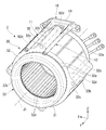
- FIG. 2 is a perspective view showing the stator and the supply pipe unit of one embodiment.
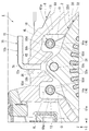
- FIG. 3 is a partial cross-sectional view of the motor unit 1 according to the embodiment.
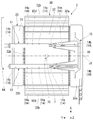
- FIG. 4 is a top view showing the stator and the supply pipe unit of one embodiment.
- the vertical direction will be defined based on the positional relationship when the motor unit 1 of the present embodiment is mounted on a vehicle (not shown) located on a horizontal road surface.
- the XYZ coordinate system is shown as a three-dimensional Cartesian coordinate system as appropriate.
- the Z-axis direction is the vertical direction.
- the + Z side is the upper side in the vertical direction
- the ⁇ Z side is the lower side in the vertical direction.
- the upper side in the vertical direction is simply referred to as "upper side”
- the lower side in the vertical direction is simply referred to as "lower side”.
- the X-axis direction is a direction orthogonal to the Z-axis direction, and is the front-back direction of the vehicle in which the motor unit 1 is mounted.
- the + X side is the front side of the vehicle
- the ⁇ X side is the rear side of the vehicle.
- the Y-axis direction is a direction orthogonal to both the X-axis direction and the Z-axis direction, and is the vehicle left-right direction, that is, the vehicle width direction.
- the + Y side is the left side of the vehicle
- the ⁇ Y side is the right side of the vehicle.
- the Y-axis direction corresponds to the axial direction of the motor axis J1 described later.
- the front-back direction and the left-right direction are horizontal directions orthogonal to the vertical direction.
- the left side corresponds to one side in the axial direction
- the right side corresponds to the other side in the axial direction.
- the front side corresponds to one side in the horizontal direction
- the rear side corresponds to the other side in the horizontal direction.
- the positional relationship in the front-rear direction is not limited to the positional relationship of the present embodiment, and the + X side may be the rear side of the vehicle and the ⁇ X side may be the front side of the vehicle.
- the + Y side is the right side of the vehicle, and the ⁇ Y side is the left side of the vehicle.
- the motor axis J1 shown in each figure extends in the Y-axis direction, that is, in the left-right direction of the vehicle.
- a direction parallel to the motor axis J1 is simply referred to as “axial direction”
- a radial direction around the motor axis J1 is simply referred to as “radial direction”
- the motor axis J1 is centered.
- the circumferential direction, that is, the circumference of the motor axis J1 is simply referred to as the "circumferential direction”.
- the one axial side (+Y side) is the axial direction from the motor housing portion 61 of the housing 6 to the gear housing portion 62, which will be described later.
- the other side ( ⁇ Y side) in the axial direction is the direction from the gear accommodating portion 62 to the motor accommodating portion 61 in the axial direction.
- the “parallel direction” includes a substantially parallel direction
- the “orthogonal direction” includes a substantially orthogonal direction.
- FIG. 1 is a conceptual diagram schematically showing the motor unit 1.
- the motor unit 1 of the present embodiment is mounted on a vehicle having a motor as a power source, such as a hybrid vehicle (HEV), a plug-in hybrid vehicle (PHV), and an electric vehicle (EV), and is used as a power source thereof.
- a vehicle having a motor as a power source such as a hybrid vehicle (HEV), a plug-in hybrid vehicle (PHV), and an electric vehicle (EV), and is used as a power source thereof.
- HEV hybrid vehicle
- HEV electric vehicle
- the motor unit 1 includes a motor 2, a gear unit 3 including a speed reducer 4 and a differential device 5, a housing 6, and an oil passage (refrigerant passage) 90.
- the oil passage 90 includes a pump 96, a cooler 97, a first supply pipe (supply unit) 11, and a second supply pipe (supply unit) 12.
- the first supply pipe 11 and the second supply pipe 12 form a part of the supply pipe unit 10.
- the housing 6 includes a motor accommodating portion 61 that accommodates the motor 2, a gear accommodating portion 62 that accommodates the gear portion 3, and a partition wall 61c that axially partitions the interior of the motor accommodating portion 61 from the gear accommodating portion 62. , And a breather unit 70.
- the gear accommodating portion 62 is located on the left side (+Y side) of the motor accommodating portion 61.
- the bottom portion 61s of the motor accommodating portion 61 is located above the bottom portion 62a of the gear accommodating portion 62.
- the partition wall 61c is provided with a partition wall opening 68.
- the partition opening 68 connects the inside of the motor housing 61 and the inside of the gear housing 62.
- the partition wall 61c is located on the left side of the stator 30.
- Oil O as a refrigerant is accommodated inside the housing 6.
- the refrigerant is oil O.
- oil (refrigerant) O is housed inside the motor housing portion 61 and inside the gear housing portion 62.
- An oil sump P for accumulating oil O is provided in a lower region inside the gear accommodating portion 62.
- the oil O in the oil sump P is sent to the inside of the motor accommodating portion 61 by the oil passage 90.
- the oil O sent to the inside of the motor housing portion 61 collects in the lower region inside the motor housing portion 61. At least a part of the oil O accumulated inside the motor accommodating portion 61 moves to the gear accommodating portion 62 through the partition wall opening 68 and returns to the oil sump P.
- Oil O circulates in an oil passage 90 described later.
- the oil O functions not only for cooling the motor 2 but also for lubricating the gear portion 3.
- Oil O is a lubricating oil for automatic transmissions (ATF: Automatic) with a relatively low viscosity in order to perform the functions of a lubricating oil and a cooling oil. It is preferable to use an oil equivalent to Transmission Fluid).
- the motor 2 is an inner rotor type motor.
- the motor 2 includes a rotor 20, a stator 30, and a plurality of bearings 26 and 27.
- the rotor 20 can rotate about the motor axis J1 extending in the horizontal direction.
- the rotor 20 has a shaft 21 and a rotor body 24.
- the rotor body 24 has a rotor core and a rotor magnet fixed to the rotor core. The torque of the rotor 20 is transmitted to the gear portion 3.
- the shaft 21 extends along the axial direction about the motor axis J1.
- the shaft 21 rotates about the motor axis J1.
- the shaft 21 is a hollow shaft provided with a hollow portion 22 inside.
- the shaft 21 is provided with a communication hole 23.
- the communication hole 23 extends in the radial direction and connects the hollow portion 22 and the outside of the shaft 21.
- the shaft 21 extends across the motor housing portion 61 and the gear housing portion 62 of the housing 6. The left end of the shaft 21 projects into the gear accommodating portion 62. A first gear 41, which will be described later, of the gear unit 3 is fixed to the left end of the shaft 21.
- the shaft 21 is rotatably supported by bearings 26 and 27.
- the stator 30 faces the rotor 20 with a gap in the radial direction.
- the stator 30 is located radially outside the rotor 20.
- the outer peripheral surface of the stator 30 faces the inner peripheral surface of the housing 6.
- the stator 30 has a stator core 32 and a coil assembly 33.
- the stator core 32 is fixed to the inner surface of the motor housing portion 61.
- FIG. 2 is a perspective view showing the stator 30 and the supply pipe unit 10 located above the stator 30.
- the stator core 32 has a cylindrical core back portion 32d extending in the axial direction, and a plurality of tooth portions 32e extending radially inward from the core back portion 32d.
- the plurality of tooth portions 32e are arranged at intervals in the circumferential direction.
- the plurality of tooth portions 32e are arranged at equal intervals over the entire circumference in the circumferential direction.
- the core back portion 32d has a plurality of fixing portions 32b protruding outward in the radial direction from the outer peripheral surface.
- the fixing portion 32b is fixed to the inner surface of the motor housing portion 61. That is, the stator 30 is fixed to the housing 6 at the fixing portion 32b.
- a plurality of fixed portions 32b are provided at intervals in the circumferential direction. For example, four fixing portions 32b are provided. The four fixing portions 32b are arranged at equal intervals over the entire circumference in the circumferential direction.
- the fixed portion 32b extends along the axial direction.
- the fixing portion 32b extends from the left (+Y side) end of the stator core 32 to the right ( ⁇ Y side) end of the stator core 32. That is, the fixed portion 32b extends over the entire axial length of the stator core 32.
- the fixing portion 32b has a through hole 32c that penetrates the fixing portion 32b in the axial direction.
- a bolt (not shown) extending in the axial direction is passed through the through hole 32c.
- the bolt is passed through the through hole 32c from the right side ( ⁇ Y side) and is tightened in a female screw hole (not shown) provided on the inner side surface of the motor housing portion 61. By tightening the bolt into the female screw hole, the fixing portion 32b is fixed to the motor accommodating portion 61.
- one of the plurality (four in this embodiment) of fixing portions 32b that protrudes upward from the outer peripheral surface of the core back portion 32d is referred to as an upper fixing portion 35. That is, one of the plurality of fixing portions 32b includes the upper fixing portion 35.
- the other fixing portions 32b project downward, forward (+ X side), and rearward ( ⁇ X side), respectively.
- the coil assembly 33 has a plurality of coils 31 attached to the stator core 32.
- the plurality of coils 31 are attached to the teeth 32e of the stator core 32 via an insulator (not shown).
- the plurality of coils 31 are arranged side by side in the circumferential direction.
- the plurality of coils 31 are arranged at equal intervals over the entire circumference in the circumferential direction.
- the coil assembly 33 may have a binding member that binds the coils 31 or the like, or may have a connecting wire that connects the coils 31 to each other.
- the coil assembly 33 has a pair of coil ends 33a and 33b projecting from the stator core 32 in the axial direction.
- the coil end 33a is a portion of the coil assembly 33 that protrudes from the stator core 32 to the right ( ⁇ Y side).
- the coil end 33b is a part of the coil assembly 33 that protrudes leftward (+Y side) from the stator core 32.
- the coil end 33a includes a portion of each coil 31 included in the coil assembly 33 that projects to the right of the stator core 32.
- the coil end 33b includes a portion of each coil 31 included in the coil assembly 33 that protrudes to the left side of the stator core 32.
- the coil ends 33a and 33b are annular with the motor axis J1 as the center.
- the coil ends 33a and 33b may include a binding member or the like that binds the coils 31, or may include a crossover connecting the coils 31 to each other.
- the bearings 26 and 27 rotatably support the rotor 20.
- the bearings 26 and 27 are, for example, ball bearings.
- the bearing 26 is a bearing that rotatably supports a portion of the rotor 20 located on the right side of the stator core 32.
- the bearing 26 supports a portion of the shaft 21 located on the right side of the portion to which the rotor body 24 is fixed.
- the bearing 26 is held by a wall portion 61b of the motor accommodating portion 61 that covers the right side of the rotor 20 and the stator 30.
- the wall portion 61b constitutes a part of the wall portion of the housing 6, and closes the opening on the right side of the motor housing portion 61.
- the bearing 27 is a bearing that rotatably supports a portion of the rotor 20 located on the left side of the stator core 32.
- the bearing 27 supports the portion of the shaft 21 located on the left side of the portion to which the rotor body 24 is fixed.
- the bearing 27 is held by the partition wall 61c.
- the gear unit 3 is housed in the gear housing unit 62 of the housing 6.
- the gear unit 3 is connected to the motor 2. More specifically, the gear portion 3 is connected to the left end of the shaft 21.
- the gear portion 3 includes a speed reducing device 4 and a differential device 5. The torque output from the motor 2 is transmitted to the differential device 5 via the speed reducer 4.
- the speed reducer 4 is connected to the motor 2.
- the speed reduction device 4 reduces the rotation speed of the motor 2 and increases the torque output from the motor 2 according to the reduction ratio.
- the speed reducing device 4 transmits the torque output from the motor 2 to the differential device 5.
- the reduction gear device 4 includes a first gear 41, a second gear 42, a third gear 43, and an intermediate shaft 45.
- the first gear 41 is fixed to the outer peripheral surface of the left end of the shaft 21.
- the first gear 41 rotates around the motor axis J1 together with the shaft 21.
- the intermediate shaft 45 extends along an intermediate axis J2 parallel to the motor axis J1.
- the intermediate shaft 45 rotates about the intermediate axis J2.
- the second gear 42 and the third gear 43 are fixed to the outer peripheral surface of the intermediate shaft 45 with a space provided therebetween in the axial direction.
- the second gear 42 and the third gear 43 are connected to each other via an intermediate shaft 45.
- the second gear 42 and the third gear 43 rotate about the intermediate axis J2.
- the second gear 42 meshes with the first gear 41.
- the third gear 43 meshes with the ring gear 51 described later of the differential device 5.
- the torque output from the motor 2 is transmitted to the ring gear 51 of the differential device 5 via the shaft 21, the first gear 41, the second gear 42, the intermediate shaft 45, and the third gear 43 in this order.
- the gear ratio of each gear, the number of gears, and the like can be appropriately changed according to the required reduction ratio.
- the speed reducer 4 is a parallel shaft gear type speed reducer in which the shaft cores of the gears are arranged in parallel.
- the differential device 5 is connected to the motor 2 via the speed reducer 4.
- the differential device 5 is a device for transmitting the torque output from the motor 2 to the wheels of the vehicle.
- the differential device 5 transmits the same torque to the axles 55 of the left and right wheels while absorbing the speed difference between the left and right wheels when the vehicle turns.
- the gear unit 3 transmits the torque of the motor 2 to the axle 55 of the vehicle via the speed reducer 4 and the differential device 5.
- the differential device 5 includes a ring gear 51, a gear housing (not shown), a pair of pinion gears (not shown), a pinion shaft (not shown), and a pair of side gears (not shown).
- the ring gear 51 rotates about the differential axis J3 parallel to the motor axis J1.
- the torque output from the motor 2 is transmitted to the ring gear 51 via the speed reducer 4.
- the oil passage 90 passes through the housing 6 and circulates the oil O.
- the oil passage 90 is a path of the oil O that supplies the oil O from the oil sump P to the gear portion 3 and the motor 2 and guides it to the oil sump P again.
- the oil passage 90 is provided so as to straddle the inside of the motor accommodating portion 61 and the inside of the gear accommodating portion 62.
- the “oil passage” means an oil passage.
- the "oil passage” is a concept that includes not only a “flow path” that constantly creates a flow of oil in one direction, but also a path for temporarily retaining oil and a path for oil to drip.
- the route for temporarily retaining the oil includes, for example, a reservoir for storing the oil.
- the oil passage 90 has a first oil passage 91 and a second oil passage 92.
- the first oil passage 91 and the second oil passage 92 circulate the oil O inside the housing 6, respectively.
- Both the first oil passage 91 and the second oil passage 92 are paths for supplying the oil O from the oil reservoir P to the motor 2 and collecting it again in the oil reservoir P.
- the oil O drips from the motor 2 and collects in the lower region inside the motor housing portion 61.
- the oil O collected in the lower region in the motor housing 61 moves to the lower region in the gear housing 62 (that is, the oil sump P) via the partition opening 68. That is, the first oil passage 91 and the second oil passage 92 include paths for moving the oil O from the lower region inside the motor housing portion 61 to the lower region inside the gear housing portion 62.
- the first oil passage 91 has a scraping path 91a, a shaft supply path 91b, an in-shaft path 91c, and an in-rotor path 91d. Further, a reservoir 93 is provided in the route of the first oil passage 91. The reservoir 93 is provided in the gear accommodating portion 62.
- the scraping path 91a is a path for scraping the oil O from the oil sump P by the rotation of the ring gear 51 of the differential device 5 and receiving the oil O in the reservoir 93.
- the reservoir 93 opens upward.
- the reservoir 93 receives the oil O picked up by the ring gear 51. Further, when the liquid surface S of the oil sump P is high, such as immediately after the motor 2 is driven, the reservoir 93 also stores the oil O scraped up by the second gear 42 and the third gear 43 in addition to the ring gear 51. receive.
- the oil O scraped by the ring gear 51 is supplied to each gear of the gear unit 3 and reaches the tooth flanks of the gear.
- the oil passage 90 passes through the inside of the gear accommodating portion 62.
- the shaft supply path 91b is a path for guiding the oil O from the reservoir 93 to the hollow portion 22 of the shaft 21.
- the in-shaft path 91c is a path through which the oil O passes through the hollow portion 22 of the shaft 21.
- the rotor internal passage 91d is a passage of the oil O that passes through the inside of the rotor main body 24 from the communication hole 23 of the shaft 21 and is scattered on the stator 30.
- Centrifugal force acts on the oil O inside the rotor 20 as the rotor 20 rotates in the path 91c in the shaft. As a result, the oil O continuously scatters radially outward from the rotor 20. Further, as the oil O scatters, the path inside the rotor 20 becomes a negative pressure, the oil O accumulated in the reservoir 93 is sucked into the rotor 20, and the path inside the rotor 20 is filled with the oil O. The oil O reaching the stator 30 takes heat from the stator 30.
- the second oil passage 92 includes a first flow passage 92a, a second flow passage 92b, a third flow passage 92c, a fourth flow passage 94, a supply pipe internal flow passage 92d, and the ejection holes 14 And.
- the first flow passage 92a, the second flow passage 92b, the third flow passage 92c, and the fourth flow passage 94 are provided on the wall portion of the housing 6.
- the first flow path 92a connects the oil sump P and the pump 96.
- the second flow path 92b connects the pump 96 and the cooler 97.
- the third flow passage 92c connects the cooler 97 and the fourth flow passage 94.
- the third flow path 92c is provided, for example, on the front (+X side) wall portion of the wall portion of the motor housing portion 61.
- the fourth flow path 94 is provided in the wall portion of the motor housing portion 61 or the partition wall 61c.
- the fourth flow path 94 is connected to the first supply pipe 11 and the second supply pipe 12 of the supply pipe unit 10. That is, the fourth flow path 94 connects the third flow path 92c and the supply pipe unit 10.
- the fourth flow path 94 extends, for example, in the horizontal direction from the portion connected to the third flow path 92c toward the rear side ( ⁇ X side).
- the supply pipe unit 10 is arranged between the inner peripheral surface 61 a of the motor housing portion 61 and the outer peripheral surface of the stator 30.
- the supply pipe unit 10 is located above the stator 30.
- the left (+Y side) end of the supply pipe unit 10 is fixed to the wall of the motor housing 61 or the partition wall 61c.
- the left end of the supply pipe unit 10 is connected to the fourth flow path 94.
- the right ( ⁇ Y side) end of the supply pipe unit 10 is fixed to the top wall or wall 61b of the motor housing 61. That is, the supply pipe unit 10 is fixed to the housing 6.
- the flow path 92d in the supply pipe is a flow path of the refrigerant arranged inside the supply pipe unit 10. More specifically, they are located inside the first supply pipe 11 and the second supply pipe 12 of the supply pipe unit 10, respectively. Therefore, the second oil passage 92 is provided with a pair of supply pipe internal passages 92d. The flow path 92d in the supply pipe extends in the axial direction. Further, the pair of supply pipe flow paths 92d are connected to the fourth flow path 94, respectively.
- the first supply pipe 11 and the second supply pipe 12 have a pipe shape extending in the axial direction.
- the first supply pipe 11 and the second supply pipe 12 are connected to each other by a connecting portion 19 located at the end portion on the right side ( ⁇ Y side). That is, the supply pipe unit 10 includes a first supply pipe 11, a second supply pipe 12, and a connecting portion 19 that connects the first supply pipe 11 and the second supply pipe 12. Further, ribs that reinforce the supply pipe unit 10 are provided between the first supply pipe 11 and the connecting portion 19 and between the second supply pipe 12 and the connecting portion 19.
- the first supply pipe 11 and the second supply pipe 12 are cylindrical pipes that extend linearly along the axial direction.
- the first supply pipe 11 and the second supply pipe 12 are arranged at intervals in the front-rear direction.
- the first supply pipe 11 and the second supply pipe 12 are parallel to each other.
- FIG. 3 is a partial cross-sectional view of the motor unit 1 including the supply pipe unit 10.
- the first supply pipe 11 and the second supply pipe 12 are located on the radial outer side of the core back portion 32d.
- the radial position of the first supply pipe 11 and the radial position of the second supply pipe 12 are the same.
- the first supply pipe 11 and the second supply pipe 12 are arranged above the core back portion 32d.
- the vertical position of the first supply pipe 11 and the vertical position of the second supply pipe 12 are the same.
- the upper fixing portion 35 is arranged between the first supply pipe 11 and the second supply pipe 12. That is, the first supply pipe 11 and the second supply pipe 12 extend along the axial direction at the side portions on both sides in the circumferential direction of the upper fixing portion 35.
- a virtual straight line (not shown) that passes through the central axis of the first supply pipe 11 and the central axis of the second supply pipe 12 intersects with the upper fixing portion 35.
- the first supply pipe 11 and the second supply pipe 12 are located on the side portion in the circumferential direction of the upper fixing portion 35.
- the first supply pipe 11 is located on one side in the circumferential direction of the upper fixing portion 35
- the second supply pipe 12 is located on the other side in the circumferential direction of the upper fixing portion 35.
- FIG. 4 is a top view showing the stator and the supply pipe unit. As shown in FIG. 4, the positions of the first supply pipe 11, the second supply pipe 12, and the upper fixing portion 35 in the front-rear direction overlap each other.
- the first supply pipe 11 is located on the front side (+ X side) of the upper fixing portion 35
- the second supply pipe 12 is located on the rear side ( ⁇ X side) of the upper fixing portion 35.
- the first supply pipe 11 and the second supply pipe 12 have a plurality of ejection holes 14 penetrating the peripheral wall. As shown in FIG. 3, the ejection hole 14 extends in the pipe radial direction orthogonal to the central axis of the first supply pipe 11 or the second supply pipe 12 and communicates the inside and outside of the pipe.
- the ejection hole 14 has, for example, a circular hole shape.
- the ejection hole 14 is located between the inner peripheral surface of the housing 6 and the outer peripheral surface of the stator 30. The ejection hole 14 ejects the oil O flowing through the flow path 92d in the supply pipe to the motor 2.
- the plurality of ejection holes 14 are arranged in the axial direction at intervals.
- the plurality of ejection holes 14 can cool the stator 30 in a wide range in the axial direction by the oil O ejected from the plurality of ejection holes 14 arranged in the axial direction.
- the ejection holes 14 are classified into a plurality of first ejection holes 14a and a plurality of second ejection holes 14b.
- the first supply pipe 11 and the second supply pipe 12 each have four first ejection holes 14a and two second ejection holes 14b.
- the two second ejection holes 14b are arranged at both ends, and the four first ejection holes 14a are located between the two second ejection holes 14b. They are arranged at equal intervals in the axial direction.
- the axial position of the first ejection hole 14a overlaps with the axial position of the stator core 32.
- the axial position of the second ejection hole 14b overlaps the axial position of the coil ends 33a and 33b.
- One of the two second ejection holes 14b located on the right side faces the right coil end 33a.
- the other of the two second ejection holes 14b located on the left side faces the coil end 33b on the left side.
- the first ejection hole 14a opens toward the opposite side and the lower side of the upper fixing portion 35. That is, the first ejection hole 14a opens toward the outer peripheral surface of the core back portion 32d and the region opposite to the upper fixing portion 35.
- the region opposite to the upper fixing portion 35 assumes a virtual line VL connecting the first supply pipe 11 and the motor axis J1, and is opposite to the region where the upper fixing portion 35 is located with the virtual line VL as a boundary.
- the first ejection hole 14a faces the side region. The first ejection hole 14a ejects oil O onto the outer peripheral surface of the core back portion 32d.
- the oil O ejected to the core back portion 32d is dropped after cooling the core back portion 32d while traveling along the outer peripheral surface of the core back portion 32d, and is accumulated in the lower region in the motor accommodating portion 61.
- the first ejection hole 14a opens toward the opposite side and the lower side of the upper fixing portion 35, so that the first ejection hole 14a opens in the region opposite to the breather portion 70. Therefore, it is possible to prevent the oil O from leaking from the breather portion 70.
- the first ejection holes 14a may be opened toward the motor axis J1.
- the second ejection hole 14b opens toward the opposite side of the upper fixing portion 35 and the lower side.
- the second ejection hole 14b provided on the right side ( ⁇ Y side) of the plurality of second ejection holes 14b supplies oil O to the coil end 33a on the right side.
- the second ejection hole 14b provided on the left side (+ Y side) of the plurality of second ejection holes 14b ejects oil O to the coil end 33b on the left side.
- the oil O ejected from the second ejection hole 14b is supplied to the coil ends 33a and 33b from above, cools the coil end 33a, and then drops and accumulates in the lower region in the motor accommodating portion 61.
- the first supply pipe 11 and the second supply pipe 12 as the supply unit 10 have a pipe shape, but the present invention is not limited to this, and for example, even if the supply unit has a gutter shape. Good.
- a breather unit 70 is provided in the housing 6.
- the breather portion 70 communicates the inside of the motor housing portion 61 with the outside of the housing 6 and adjusts the internal pressure of the motor housing portion 61. More specifically, the breather portion 70 lubricates the speed reducer 4, the differential gear 5 and each bearing and cools the motor 2 in the housing 6 of the motor unit 1 by an axial center oil supply method or an oil bath lubrication method. In order to prevent the oil O from leaking from the housing 6 when the internal pressure inside the housing 6 rises due to the temperature rise inside the housing 6 during operation, the internal pressure inside the housing 6 is adjusted. ing.
- the breather portion 70 has a vent hole portion 71 for communicating the inside and outside of the motor housing portion 61, and a pipe 72 attached to the vent hole portion 71.
- the vent hole portion 71 is a circular hole. Further, the vent hole portion 71 extends linearly along the vertical direction.
- the pipe 72 is inserted into the ventilation hole 71. Both ends of the pipe 72 are open to connect the inside of the ventilation hole 71 and the outside of the housing 6.
- the pipe 72 is L-shaped having a first portion 72a and a second portion 72b bent with respect to the first portion 72a.
- the first portion 72a is a portion to be inserted into the ventilation hole portion 71 from above.
- the first portion 72a extends in the vertical direction about the central axis J4.
- the second portion 72b extends from the upper end of the first portion 72a in a direction orthogonal to the vertical direction.
- the second portion 72b is located outside the housing 6.
- a hose (not shown) may be provided at the tip of the second portion 72b.
- a filter may be provided at the tip of the hose.
- the motor 2 is surrounded by the inner peripheral surface 61a of the motor accommodating portion 61 from the outside in the radial direction.
- the inner peripheral surface 61a of the motor accommodating portion 61 has a substantially circular shape centered on the motor axis J1.
- a plurality of recesses 61k in which the fixing portion 32b is accommodated are provided on the inner peripheral surface 61a of the motor accommodating portion 61.
- the recess 61k is recessed outward in the radial direction. Further, the recess 61k extends along the axial direction.
- the core back portion 32d is provided with four fixing portions 32b. Therefore, the inner peripheral surface 61a of the motor housing portion 61 is provided with four recesses 61k.
- a slight gap is provided between the inner surface of the recess 61k and the outer surface of the fixed portion 32b housed in the recess 61k.
- the recess 61k accommodating the upper fixing portion 35 is referred to as the upper recess 65.
- the vent hole 71 of the breather portion 70 opens in the upper recess 65.
- a recess is further formed from the inner peripheral surface of the upper recess 65, and the opening of the vent hole portion 71 is formed on the bottom surface thereof. That is, the breather portion 70 opens into the motor housing portion 61 in the upper recess 65.
- the breather portion 70 is located above the upper fixed portion 35 housed in the upper recess 65.
- the opening of the vent hole portion 71 is located at the top (that is, the highest portion) of the inner surface of the upper recess 65.
- the breather portion 70 is arranged so as to overlap the upper fixing portion 35 when viewed from the vertical direction. That is, the breather portion 70 is located directly above the upper fixing portion 35. Further, the axial position of the opening of the breather portion 70 in the motor housing portion 61 is substantially the intermediate position of the stator 30, and is displaced from the axial positions of the ejection holes 14 of the first supply pipe 11 and the second supply pipe 12. Will be placed.
- the inner peripheral surface 61a of the motor accommodating portion 61 is provided with a supply pipe accommodating recess 61p in which the supply portion (first supply pipe 11 or second supply pipe 12) is accommodated.
- the inner peripheral surface 61a of the present embodiment is provided with two supply pipe housing recesses 61p corresponding to the two supply units (the first supply pipe 11 and the second supply pipe 12).
- the two supply pipe accommodating recesses 61p are arranged on both sides of the upper recess 65 in the circumferential direction.
- the first supply pipe 11 is housed inside one of the two supply pipe housing recesses 61p, and the second supply pipe 12 is housed inside the other.
- the breather portion 70 since the breather portion 70 is located above the stator core 32, the oil O in the motor housing portion 61 leaks in and out of the breather portion 70 even when the vehicle travels on a slope. Can be suppressed. As a result, even when the vehicle travels on a slope, the breather section 70 can appropriately adjust the internal pressure in the motor housing section 61.
- the breather portion 70 is located above the upper fixed portion 35.
- the upper fixing portion 35 projects upward with respect to the outer peripheral surface of the core back portion 32d. Therefore, according to the present embodiment, the opening of the breather portion 70 can be separated from the path through which the oil O flows, and the oil O can be prevented from leaking from the breather portion 70.
- the first supply pipe 11 and the second supply pipe 12 are located on the circumferential side portions of the upper fixing portion 35.
- the oil O supplied from the first supply pipe 11 and the second supply pipe 12 to the outer peripheral surface of the core back portion 32d is blocked by the upper fixing portion 35 and is difficult to reach the opening of the breather portion 70. As a result, it is possible to prevent oil O from leaking from the breather portion 70.
- the supply unit for supplying the oil O to the motor 2 is a pipe-shaped supply pipe (first supply pipe 11 and second supply pipe 12) having an ejection hole 14.
- the pressure of the oil O in the flow path can be increased and the flow velocity of the oil ejected from the ejection holes 14 can be increased.
- the oil O can be scattered over a wide range from the ejection hole 14, and the wide range on the surface of the motor 2 can be cooled in a well-balanced manner.
- the first ejection holes 14a open toward the region on the outer peripheral surface of the core back portion 32d opposite to the upper fixing portion 35. That is, the oil O ejected from the first ejection hole 14 a is ejected toward the opposite side of the breather portion 70. Therefore, it is difficult for the oil O ejected from the first ejection hole 14a to enter the opening of the breather portion 70, and it is possible to prevent the oil O from leaking from the breather portion 70.
- the breather portion 70 opens into the motor housing portion 61 in the upper recess 65 in which the upper fixing portion 35 is stored.
- the oil O does not reach the opening of the breather portion 70 unless it passes through the gap between the inner surface of the upper concave portion 65 and the outer surface of the upper fixing portion 35. That is, according to the present embodiment, it is difficult for the oil O to enter the opening of the breather portion 70, and it is possible to prevent the oil O from leaking from the breather portion 70.
- the opening of the breather portion 70 in the motor housing portion 61 and the first ejection hole 14a are arranged at different positions in the axial direction. That is, in the present embodiment, the breather unit 70 is located at a position axially different from the ejection hole arranged in one of the two supply units (first supply pipe 11 and second supply pipe 12). It should be arranged.
- the supply part is a pipe having a plurality of ejection holes, and the breather part is located within the axial length of the pipe. Further, the breather portion is arranged at a position where none of the plurality of ejection holes overlaps in the axial direction.
- the breather unit is arranged at a position where none of the plurality of ejection holes located in the two supply units overlap in the axial direction. Therefore, it is difficult for the oil O ejected from the first ejection hole 14a to enter the opening of the breather portion 70, and it is possible to prevent the oil O from leaking from the breather portion 70. Even if the ejection holes of one of the two supply units are axially different from the breather unit and the ejection holes of the other supply unit are axially the same position as the breather unit, the breather It is possible to obtain a certain effect of suppressing the leakage of oil from the part.
- the two supply parts are located on both sides in the circumferential direction of the upper fixed part 35. Therefore, the oil O can be supplied to both sides in the circumferential direction of the outer peripheral surface of the core back portion 32d around the upper fixed portion 35, and the entire stator core 32 can be cooled in a well-balanced manner.
Abstract
A motor unit according to one aspect of the present invention is provided with: a motor having a rotor rotating around the motor axis line and a stator positioned radially outside the rotor; a housing having a motor accommodation part that accommodates the motor; and a refrigerant path for circulating a refrigerant through the inside of the housing. A core back part of the stator has a plurality of fixed sections that protrude radially outward from the outer circumferential surface thereof, extend in the axial direction, and are fixed to the housing. The plurality of fixed sections include an upper fixed section protruding upward from the outer circumferential surface of the core back part. The refrigerant path has a supply part that supplies the refrigerant to the outer circumferential surface of the core back part. The supply part is positioned on a circumferential side section of the upper fixed section. The housing is provided with a breather part that is positioned above the upper fixed section and communicates between the inside of the motor accommodation part and the outside of the housing.
Description
本発明は、モータユニットに関する。
本願は、2019年3月6日に日本に出願された特願2019-040863号、2019年4月11日に日本に出願された特願2019-075237号および2019年6月13日に日本に出願された特願2019-110648号に基づき優先権を主張し、その内容をここに援用する。 The present invention relates to a motor unit.
This application applies to Japanese Patent Application No. 2019-040863 filed in Japan on March 6, 2019, Japanese Patent Application No. 2019-075237 filed in Japan on April 11, 2019, and to Japan on June 13, 2019. Priority is claimed based on the filed Japanese Patent Application No. 2019-110648, the contents of which are incorporated herein.
モータとギヤ部とを備えたモータユニットにおいて、モータハウジング内の圧力を調整するブリーザ機構を備える構造が知られている。特許文献1には、ギヤ室からブリーザ機構に繋がる経路中にモータ室に繋がる連通路が設けられるモータケースが開示されている。この構成によれば、作動油がブリーザ装置から漏出することを抑制できる。
In a motor unit that includes a motor and a gear unit, a structure that includes a breather mechanism that adjusts the pressure inside the motor housing is known. Patent Document 1 discloses a motor case in which a communication passage connected to the motor chamber is provided in a path connecting the gear chamber to the breather mechanism. According to this configuration, it is possible to prevent the hydraulic oil from leaking from the breather device.
しかしながら、従来構造では、車両が坂道を走行する場合などにおける漏出の抑制に対して十分考慮されておらず、このため、ブリーザ部からオイルが漏出する虞があった。
However, in the conventional structure, sufficient consideration is not given to the suppression of leakage when the vehicle travels on a slope, and therefore, there is a risk that oil may leak from the breather portion.
上記事情に鑑み、本発明は、ブリーザ部からのオイルの漏出を抑制できるモータユニットの提供することを目的の一つとする。
In view of the above circumstances, it is an object of the present invention to provide a motor unit that can suppress the leakage of oil from the breather section.
本発明のモータユニットの一つの態様は、モータ軸線を中心として回転するロータおよび前記ロータの径方向外側に位置するステータを有するモータと、前記モータを収容するモータ収容部を有するハウジングと、前記ハウジング内を通り冷媒を循環させる冷媒経路と、を備える。前記ステータのコアバック部は、外周面から径方向外側に突出し軸方向に沿って延び、前記ハウジングに固定される複数の固定部を有する。複数の前記固定部は、前記コアバック部の外周面から上方に突出する上側固定部を含む。前記冷媒経路は、前記コアバック部の外周面に前記冷媒を供給する供給部を有する。前記供給部は、前記上側固定部の周方向の側部に位置する。前記ハウジングには、前記上側固定部の上方に位置し前記モータ収容部の内部と前記ハウジングの外部とを連通させるブリーザ部が設けられる。
One aspect of a motor unit of the present invention is a motor having a rotor that rotates about a motor axis and a stator that is positioned radially outside the rotor, a housing having a motor housing portion that houses the motor, and the housing. It is provided with a refrigerant path for circulating the refrigerant through the inside. The core back portion of the stator has a plurality of fixing portions that protrude radially outward from the outer peripheral surface, extend along the axial direction, and are fixed to the housing. The plurality of fixing portions include an upper fixing portion protruding upward from the outer peripheral surface of the core back portion. The coolant path has a supply unit that supplies the coolant to the outer peripheral surface of the core back unit. The supply unit is located on a circumferential side portion of the upper fixing unit. The housing is provided with a breather portion which is located above the upper fixing portion and which communicates the inside of the motor housing portion with the outside of the housing.
本発明の一つの態様のモータユニットによれば、ブリーザ部からのオイルの漏出を抑制できるモータユニットを提供できる。
According to the motor unit of one aspect of the present invention, it is possible to provide a motor unit capable of suppressing the leakage of oil from the breather portion.
以下の説明では、本実施形態のモータユニット1が水平な路面上に位置する図示しない車両に搭載された場合の位置関係を基に、鉛直方向を規定して説明する。また、図面においては、適宜3次元直交座標系としてXYZ座標系を示す。XYZ座標系において、Z軸方向は、鉛直方向である。+Z側は、鉛直方向上側であり、-Z側は、鉛直方向下側である。本実施形態では、鉛直方向上側を単に「上側」と呼び、鉛直方向下側を単に「下側」と呼ぶ。X軸方向は、Z軸方向と直交する方向であって、モータユニット1が搭載される車両の前後方向である。本実施形態において、+X側は、車両の前側であり、-X側は、車両の後側である。Y軸方向は、X軸方向とZ軸方向との両方と直交する方向であって、車両の左右方向、すなわち車幅方向である。本実施形態において、+Y側は、車両の左側であり、-Y側は、車両の右側である。Y軸方向は、後述するモータ軸線J1の軸方向に相当する。前後方向および左右方向は、鉛直方向と直交する水平方向である。本実施形態において、左側は、軸方向一方側に相当し、右側は、軸方向他方側に相当する。また前側は、水平方向一方側に相当し、後側は水平方向他方側に相当する。
In the following description, the vertical direction will be defined based on the positional relationship when the motor unit 1 of the present embodiment is mounted on a vehicle (not shown) located on a horizontal road surface. Further, in the drawings, the XYZ coordinate system is shown as a three-dimensional Cartesian coordinate system as appropriate. In the XYZ coordinate system, the Z-axis direction is the vertical direction. The + Z side is the upper side in the vertical direction, and the −Z side is the lower side in the vertical direction. In the present embodiment, the upper side in the vertical direction is simply referred to as "upper side", and the lower side in the vertical direction is simply referred to as "lower side". The X-axis direction is a direction orthogonal to the Z-axis direction, and is the front-back direction of the vehicle in which the motor unit 1 is mounted. In the present embodiment, the + X side is the front side of the vehicle, and the −X side is the rear side of the vehicle. The Y-axis direction is a direction orthogonal to both the X-axis direction and the Z-axis direction, and is the vehicle left-right direction, that is, the vehicle width direction. In the present embodiment, the + Y side is the left side of the vehicle, and the −Y side is the right side of the vehicle. The Y-axis direction corresponds to the axial direction of the motor axis J1 described later. The front-back direction and the left-right direction are horizontal directions orthogonal to the vertical direction. In the present embodiment, the left side corresponds to one side in the axial direction, and the right side corresponds to the other side in the axial direction. The front side corresponds to one side in the horizontal direction, and the rear side corresponds to the other side in the horizontal direction.
なお、前後方向の位置関係は、本実施形態の位置関係に限られず、+X側が車両の後側であり、-X側が車両の前側であってもよい。この場合には、+Y側は、車両の右側であり、-Y側は、車両の左側である。
The positional relationship in the front-rear direction is not limited to the positional relationship of the present embodiment, and the + X side may be the rear side of the vehicle and the −X side may be the front side of the vehicle. In this case, the + Y side is the right side of the vehicle, and the −Y side is the left side of the vehicle.
各図に適宜示すモータ軸線J1は、Y軸方向、すなわち車両の左右方向に延びる。本実施形態では、特に断りのない限り、モータ軸線J1に平行な方向を単に「軸方向」と呼び、モータ軸線J1を中心とする径方向を単に「径方向」と呼び、モータ軸線J1を中心とする周方向、すなわち、モータ軸線J1の軸回りを単に「周方向」と呼ぶ。本実施形態において、軸方向一方側(+Y側)は、軸方向のうち、後述するハウジング6のモータ収容部61からギヤ収容部62へ向かう方向である。軸方向他方側(-Y側)は、軸方向のうち、ギヤ収容部62からモータ収容部61へ向かう方向である。なお、本実施形態において、「平行な方向」は略平行な方向を含み、「直交する方向」は略直交する方向を含む。
The motor axis J1 shown in each figure extends in the Y-axis direction, that is, in the left-right direction of the vehicle. In the present embodiment, unless otherwise specified, a direction parallel to the motor axis J1 is simply referred to as “axial direction”, a radial direction around the motor axis J1 is simply referred to as “radial direction”, and the motor axis J1 is centered. The circumferential direction, that is, the circumference of the motor axis J1 is simply referred to as the "circumferential direction". In the present embodiment, the one axial side (+Y side) is the axial direction from the motor housing portion 61 of the housing 6 to the gear housing portion 62, which will be described later. The other side (−Y side) in the axial direction is the direction from the gear accommodating portion 62 to the motor accommodating portion 61 in the axial direction. In the present embodiment, the “parallel direction” includes a substantially parallel direction, and the “orthogonal direction” includes a substantially orthogonal direction.
図1は、モータユニット1を模式的に示す概念図である。本実施形態のモータユニット1は、ハイブリッド自動車(HEV)、プラグインハイブリッド自動車(PHV)、電気自動車(EV)等、モータを動力源とする車両に搭載され、その動力源として使用される。
FIG. 1 is a conceptual diagram schematically showing the motor unit 1. The motor unit 1 of the present embodiment is mounted on a vehicle having a motor as a power source, such as a hybrid vehicle (HEV), a plug-in hybrid vehicle (PHV), and an electric vehicle (EV), and is used as a power source thereof.
モータユニット1は、モータ2と、減速装置4および差動装置5を含むギヤ部3と、ハウジング6と、油路(冷媒経路)90と、を備える。油路90は、ポンプ96と、クーラー97と、第1供給管(供給部)11と、第2供給管(供給部)12と、を有する。なお、第1供給管11および第2供給管12は、供給管ユニット10の一部を構成する。
The motor unit 1 includes a motor 2, a gear unit 3 including a speed reducer 4 and a differential device 5, a housing 6, and an oil passage (refrigerant passage) 90. The oil passage 90 includes a pump 96, a cooler 97, a first supply pipe (supply unit) 11, and a second supply pipe (supply unit) 12. The first supply pipe 11 and the second supply pipe 12 form a part of the supply pipe unit 10.
ハウジング6は、モータ2を収容するモータ収容部61と、ギヤ部3を収容するギヤ収容部62と、モータ収容部61の内部とギヤ収容部62の内部とを軸方向に区画する隔壁61cと、ブリーザ部70と、を有する。ギヤ収容部62は、モータ収容部61の左側(+Y側)に位置する。モータ収容部61の底部61sは、ギヤ収容部62の底部62aより上側に位置する。隔壁61cには、隔壁開口68が設けられる。隔壁開口68は、モータ収容部61の内部とギヤ収容部62の内部とを繋ぐ。隔壁61cは、ステータ30の左側に位置する。
The housing 6 includes a motor accommodating portion 61 that accommodates the motor 2, a gear accommodating portion 62 that accommodates the gear portion 3, and a partition wall 61c that axially partitions the interior of the motor accommodating portion 61 from the gear accommodating portion 62. , And a breather unit 70. The gear accommodating portion 62 is located on the left side (+Y side) of the motor accommodating portion 61. The bottom portion 61s of the motor accommodating portion 61 is located above the bottom portion 62a of the gear accommodating portion 62. The partition wall 61c is provided with a partition wall opening 68. The partition opening 68 connects the inside of the motor housing 61 and the inside of the gear housing 62. The partition wall 61c is located on the left side of the stator 30.
ハウジング6の内部には、冷媒としてのオイルOが収容される。本実施形態において、冷媒はオイルOである。本実施形態では、モータ収容部61の内部およびギヤ収容部62の内部に、オイル(冷媒)Oが収容される。ギヤ収容部62の内部における下部領域には、オイルOが溜るオイル溜りPが設けられる。オイル溜りPのオイルOは、油路90によってモータ収容部61の内部に送られる。モータ収容部61の内部に送られたオイルOは
、モータ収容部61の内部における下部領域に溜まる。モータ収容部61の内部に溜まったオイルOの少なくとも一部は、隔壁開口68を介してギヤ収容部62に移動し、オイル溜りPに戻る。 Oil O as a refrigerant is accommodated inside thehousing 6. In the present embodiment, the refrigerant is oil O. In the present embodiment, oil (refrigerant) O is housed inside the motor housing portion 61 and inside the gear housing portion 62. An oil sump P for accumulating oil O is provided in a lower region inside the gear accommodating portion 62. The oil O in the oil sump P is sent to the inside of the motor accommodating portion 61 by the oil passage 90. The oil O sent to the inside of the motor housing portion 61 collects in the lower region inside the motor housing portion 61. At least a part of the oil O accumulated inside the motor accommodating portion 61 moves to the gear accommodating portion 62 through the partition wall opening 68 and returns to the oil sump P.
、モータ収容部61の内部における下部領域に溜まる。モータ収容部61の内部に溜まったオイルOの少なくとも一部は、隔壁開口68を介してギヤ収容部62に移動し、オイル溜りPに戻る。 Oil O as a refrigerant is accommodated inside the
オイルOは、後述する油路90内を循環する。オイルOは、モータ2の冷却用として機能するのみならず、ギヤ部3の潤滑用としても機能する。オイルOとしては、潤滑油および冷却油の機能を奏するために、比較的粘度の低いオートマチックトランスミッション用潤滑油(ATF:Automatic
Transmission Fluid)と同等のオイルを用いることが好ましい。 The oil O circulates in anoil passage 90 described later. The oil O functions not only for cooling the motor 2 but also for lubricating the gear portion 3. Oil O is a lubricating oil for automatic transmissions (ATF: Automatic) with a relatively low viscosity in order to perform the functions of a lubricating oil and a cooling oil.
It is preferable to use an oil equivalent to Transmission Fluid).
Transmission Fluid)と同等のオイルを用いることが好ましい。 The oil O circulates in an
It is preferable to use an oil equivalent to Transmission Fluid).
本実施形態においてモータ2は、インナーロータ型のモータである。モータ2は、ロータ20と、ステータ30と、複数のベアリング26,27と、を備える。ロータ20は、水平方向に延びるモータ軸線J1を中心として回転可能する。ロータ20は、シャフト21と、ロータ本体24と、を有する。図示は省略するが、ロータ本体24は、ロータコアと、ロータコアに固定されるロータマグネットと、を有する。ロータ20のトルクは、ギヤ部3に伝達される。
In the present embodiment, the motor 2 is an inner rotor type motor. The motor 2 includes a rotor 20, a stator 30, and a plurality of bearings 26 and 27. The rotor 20 can rotate about the motor axis J1 extending in the horizontal direction. The rotor 20 has a shaft 21 and a rotor body 24. Although not shown, the rotor body 24 has a rotor core and a rotor magnet fixed to the rotor core. The torque of the rotor 20 is transmitted to the gear portion 3.
シャフト21は、モータ軸線J1を中心として軸方向に沿って延びる。シャフト21は、モータ軸線J1を中心として回転する。シャフト21は、内部に中空部22が設けられた中空シャフトである。シャフト21には、連通孔23が設けられる。連通孔23は、径方向に延びて中空部22とシャフト21の外部とを繋ぐ。
The shaft 21 extends along the axial direction about the motor axis J1. The shaft 21 rotates about the motor axis J1. The shaft 21 is a hollow shaft provided with a hollow portion 22 inside. The shaft 21 is provided with a communication hole 23. The communication hole 23 extends in the radial direction and connects the hollow portion 22 and the outside of the shaft 21.
シャフト21は、ハウジング6のモータ収容部61とギヤ収容部62とに跨って延びる。シャフト21の左側の端部は、ギヤ収容部62の内部に突出する。シャフト21の左側の端部には、ギヤ部3の後述する第1のギヤ41が固定される。シャフト21は、ベアリング26,27により回転可能に支持される。
The shaft 21 extends across the motor housing portion 61 and the gear housing portion 62 of the housing 6. The left end of the shaft 21 projects into the gear accommodating portion 62. A first gear 41, which will be described later, of the gear unit 3 is fixed to the left end of the shaft 21. The shaft 21 is rotatably supported by bearings 26 and 27.
ステータ30は、ロータ20と径方向に隙間をあけて対向する。ステータ30は、ロータ20の径方向外側に位置する。ステータ30の外周面は、ハウジング6の内周面と対向する。ステータ30は、ステータコア32と、コイルアセンブリ33と、を有する。ステータコア32は、モータ収容部61の内側面に固定される。
The stator 30 faces the rotor 20 with a gap in the radial direction. The stator 30 is located radially outside the rotor 20. The outer peripheral surface of the stator 30 faces the inner peripheral surface of the housing 6. The stator 30 has a stator core 32 and a coil assembly 33. The stator core 32 is fixed to the inner surface of the motor housing portion 61.
図2は、ステータ30およびステータ30の上側に位置する供給管ユニット10を示す斜視図である。
ステータコア32は、軸方向に延びる円筒状のコアバック部32dと、コアバック部32dから径方向内側に延びる複数のティース部32eと、を有する。複数のティース部32eは、周方向に互いに間隔をあけて配置される。複数のティース部32eは、周方向の全周にわたり等間隔に配置される。 FIG. 2 is a perspective view showing thestator 30 and the supply pipe unit 10 located above the stator 30.
Thestator core 32 has a cylindrical core back portion 32d extending in the axial direction, and a plurality of tooth portions 32e extending radially inward from the core back portion 32d. The plurality of tooth portions 32e are arranged at intervals in the circumferential direction. The plurality of tooth portions 32e are arranged at equal intervals over the entire circumference in the circumferential direction.
ステータコア32は、軸方向に延びる円筒状のコアバック部32dと、コアバック部32dから径方向内側に延びる複数のティース部32eと、を有する。複数のティース部32eは、周方向に互いに間隔をあけて配置される。複数のティース部32eは、周方向の全周にわたり等間隔に配置される。 FIG. 2 is a perspective view showing the
The
コアバック部32dは、外周面から径方向外側に突出する複数の固定部32bを有する。固定部32bは、モータ収容部61の内側面に固定される。すなわち、ステータ30は、固定部32bにおいて、ハウジング6に固定される。固定部32bは、周方向に互いに間隔をあけて複数設けられる。固定部32bは、例えば、4つ設けられる。4つの固定部32bは、周方向の全周にわたり等間隔に配置される。
The core back portion 32d has a plurality of fixing portions 32b protruding outward in the radial direction from the outer peripheral surface. The fixing portion 32b is fixed to the inner surface of the motor housing portion 61. That is, the stator 30 is fixed to the housing 6 at the fixing portion 32b. A plurality of fixed portions 32b are provided at intervals in the circumferential direction. For example, four fixing portions 32b are provided. The four fixing portions 32b are arranged at equal intervals over the entire circumference in the circumferential direction.
固定部32bは、軸方向に沿って延びる。本実施形態では固定部32bが、ステータコア32の左側(+Y側)の端部からステータコア32の右側(-Y側)の端部まで延びる。つまり固定部32bは、ステータコア32の軸方向の全長にわたって延びる。
The fixed portion 32b extends along the axial direction. In the present embodiment, the fixing portion 32b extends from the left (+Y side) end of the stator core 32 to the right (−Y side) end of the stator core 32. That is, the fixed portion 32b extends over the entire axial length of the stator core 32.
固定部32bは、固定部32bを軸方向に貫通する貫通孔32cを有する。貫通孔32cには、軸方向に延びる図示しないボルトが通される。ボルトは、右側(-Y側)から貫通孔32cに通され、モータ収容部61の内側面に設けられた図示しない雌ネジ穴に締め込まれる。ボルトが雌ネジ穴に締め込まれることで、固定部32bは、モータ収容部61と固定される。
The fixing portion 32b has a through hole 32c that penetrates the fixing portion 32b in the axial direction. A bolt (not shown) extending in the axial direction is passed through the through hole 32c. The bolt is passed through the through hole 32c from the right side (−Y side) and is tightened in a female screw hole (not shown) provided on the inner side surface of the motor housing portion 61. By tightening the bolt into the female screw hole, the fixing portion 32b is fixed to the motor accommodating portion 61.
本明細書の以下の説明において、複数(本実施形態において4つ)の固定部32bのうち、コアバック部32dの外周面から上方に突出する1つを上側固定部35と呼ぶこととする。すなわち、複数の固定部32bの1つは、上側固定部35を含む。なお、他の固定部32bは、それぞれ、下方、前方(+X側)、後方(-X側)に突出する。
In the following description of this specification, one of the plurality (four in this embodiment) of fixing portions 32b that protrudes upward from the outer peripheral surface of the core back portion 32d is referred to as an upper fixing portion 35. That is, one of the plurality of fixing portions 32b includes the upper fixing portion 35. The other fixing portions 32b project downward, forward (+ X side), and rearward (−X side), respectively.
図1に示すように、コイルアセンブリ33は、ステータコア32に取り付けられる複数のコイル31を有する。複数のコイル31は、図示しないインシュレータを介してステータコア32の各ティース部32eにそれぞれ装着される。複数のコイル31は、周方向に並んで配置される。複数のコイル31は、周方向の全周にわたって等間隔に配置される。図示は省略するが、コイルアセンブリ33は、各コイル31を結束する結束部材等を有してもよいし、各コイル31同士を繋ぐ渡り線を有してもよい。
As shown in FIG. 1, the coil assembly 33 has a plurality of coils 31 attached to the stator core 32. The plurality of coils 31 are attached to the teeth 32e of the stator core 32 via an insulator (not shown). The plurality of coils 31 are arranged side by side in the circumferential direction. The plurality of coils 31 are arranged at equal intervals over the entire circumference in the circumferential direction. Although illustration is omitted, the coil assembly 33 may have a binding member that binds the coils 31 or the like, or may have a connecting wire that connects the coils 31 to each other.
コイルアセンブリ33は、ステータコア32から軸方向に突出する一対のコイルエンド33a,33bを有する。コイルエンド33aは、コイルアセンブリ33のうち、ステータコア32から右側(-Y側)に突出する部分である。コイルエンド33bは、コイルアセンブリ33のうち、ステータコア32から左側(+Y側)に突出する部分である。コイルエンド33aは、コイルアセンブリ33に含まれる各コイル31のうちステータコア32よりも右側に突出する部分を含む。コイルエンド33bは、コイルアセンブリ33に含まれる各コイル31のうちステータコア32よりも左側に突出する部分を含む。
The coil assembly 33 has a pair of coil ends 33a and 33b projecting from the stator core 32 in the axial direction. The coil end 33a is a portion of the coil assembly 33 that protrudes from the stator core 32 to the right (−Y side). The coil end 33b is a part of the coil assembly 33 that protrudes leftward (+Y side) from the stator core 32. The coil end 33a includes a portion of each coil 31 included in the coil assembly 33 that projects to the right of the stator core 32. The coil end 33b includes a portion of each coil 31 included in the coil assembly 33 that protrudes to the left side of the stator core 32.
図2に示すように、本実施形態においてコイルエンド33a,33bは、モータ軸線J1を中心とする円環状である。図示は省略するが、コイルエンド33a,33bは、各コイル31を結束する結束部材等を含んでもよいし、各コイル31同士を繋ぐ渡り線を含んでもよい。
As shown in FIG. 2, in the present embodiment, the coil ends 33a and 33b are annular with the motor axis J1 as the center. Although not shown, the coil ends 33a and 33b may include a binding member or the like that binds the coils 31, or may include a crossover connecting the coils 31 to each other.
図1に示すように、ベアリング26,27は、ロータ20を回転可能に支持する。ベアリング26,27は、例えば、ボールベアリングである。ベアリング26は、ロータ20のうちステータコア32よりも右側に位置する部分を回転可能に支持するベアリングである。本実施形態においてベアリング26は、シャフト21のうちロータ本体24が固定される部分よりも右側に位置する部分を支持する。ベアリング26は、モータ収容部61のうちロータ20およびステータ30の右側を覆う壁部61bに保持される。壁部61bは、ハウジング6の壁部の一部を構成し、モータ収容部61の右側の開口を塞ぐ。
As shown in FIG. 1, the bearings 26 and 27 rotatably support the rotor 20. The bearings 26 and 27 are, for example, ball bearings. The bearing 26 is a bearing that rotatably supports a portion of the rotor 20 located on the right side of the stator core 32. In the present embodiment, the bearing 26 supports a portion of the shaft 21 located on the right side of the portion to which the rotor body 24 is fixed. The bearing 26 is held by a wall portion 61b of the motor accommodating portion 61 that covers the right side of the rotor 20 and the stator 30. The wall portion 61b constitutes a part of the wall portion of the housing 6, and closes the opening on the right side of the motor housing portion 61.
ベアリング27は、ロータ20のうちステータコア32よりも左側に位置する部分を回転可能に支持するベアリングである。本実施形態においてベアリング27は、シャフト21のうちロータ本体24が固定される部分よりも左側に位置する部分を支持する。ベアリング27は、隔壁61cに保持される。
The bearing 27 is a bearing that rotatably supports a portion of the rotor 20 located on the left side of the stator core 32. In the present embodiment, the bearing 27 supports the portion of the shaft 21 located on the left side of the portion to which the rotor body 24 is fixed. The bearing 27 is held by the partition wall 61c.
ギヤ部3は、ハウジング6のギヤ収容部62に収容される。ギヤ部3は、モータ2に接続される。より詳細には、ギヤ部3は、シャフト21の左側の端部に接続される。ギヤ部3は、減速装置4と、差動装置5と、を有する。モータ2から出力されるトルクは、減速装置4を介して差動装置5に伝達される。
The gear unit 3 is housed in the gear housing unit 62 of the housing 6. The gear unit 3 is connected to the motor 2. More specifically, the gear portion 3 is connected to the left end of the shaft 21. The gear portion 3 includes a speed reducing device 4 and a differential device 5. The torque output from the motor 2 is transmitted to the differential device 5 via the speed reducer 4.
減速装置4は、モータ2に接続される。減速装置4は、モータ2の回転速度を減じて、モータ2から出力されるトルクを減速比に応じて増大させる。減速装置4は、モータ2から出力されるトルクを差動装置5へ伝達する。減速装置4は、第1のギヤ41と、第2のギヤ42と、第3のギヤ43と、中間シャフト45と、を有する。
The speed reducer 4 is connected to the motor 2. The speed reduction device 4 reduces the rotation speed of the motor 2 and increases the torque output from the motor 2 according to the reduction ratio. The speed reducing device 4 transmits the torque output from the motor 2 to the differential device 5. The reduction gear device 4 includes a first gear 41, a second gear 42, a third gear 43, and an intermediate shaft 45.
第1のギヤ41は、シャフト21の左側の端部における外周面に固定される。第1のギヤ41は、シャフト21とともに、モータ軸線J1を中心に回転する。中間シャフト45は、モータ軸線J1と平行な中間軸線J2に沿って延びる。中間シャフト45は、中間軸線J2を中心として回転する。第2のギヤ42および第3のギヤ43は、中間シャフト45の外周面に、軸方向に互いに間隔をあけて固定される。第2のギヤ42と第3のギヤ43とは、中間シャフト45を介して互いに接続される。第2のギヤ42および第3のギヤ43は、中間軸線J2を中心として回転する。第2のギヤ42は、第1のギヤ41に噛み合う。第3のギヤ43は、差動装置5の後述するリングギヤ51と噛み合う。
The first gear 41 is fixed to the outer peripheral surface of the left end of the shaft 21. The first gear 41 rotates around the motor axis J1 together with the shaft 21. The intermediate shaft 45 extends along an intermediate axis J2 parallel to the motor axis J1. The intermediate shaft 45 rotates about the intermediate axis J2. The second gear 42 and the third gear 43 are fixed to the outer peripheral surface of the intermediate shaft 45 with a space provided therebetween in the axial direction. The second gear 42 and the third gear 43 are connected to each other via an intermediate shaft 45. The second gear 42 and the third gear 43 rotate about the intermediate axis J2. The second gear 42 meshes with the first gear 41. The third gear 43 meshes with the ring gear 51 described later of the differential device 5.
モータ2から出力されるトルクは、シャフト21、第1のギヤ41、第2のギヤ42、中間シャフト45および第3のギヤ43をこの順に介して差動装置5のリングギヤ51へ伝達される。各ギヤのギヤ比およびギヤの個数等は、必要とされる減速比に応じて適宜変更可能である。本実施形態において減速装置4は、各ギヤの軸芯が平行に配置される平行軸歯車タイプの減速機である。
The torque output from the motor 2 is transmitted to the ring gear 51 of the differential device 5 via the shaft 21, the first gear 41, the second gear 42, the intermediate shaft 45, and the third gear 43 in this order. The gear ratio of each gear, the number of gears, and the like can be appropriately changed according to the required reduction ratio. In the present embodiment, the speed reducer 4 is a parallel shaft gear type speed reducer in which the shaft cores of the gears are arranged in parallel.
差動装置5は、減速装置4を介してモータ2に接続される。差動装置5は、モータ2から出力されるトルクを車両の車輪に伝達するための装置である。差動装置5は、車両の旋回時に、左右の車輪の速度差を吸収しつつ、左右両輪の車軸55に同トルクを伝える。このように、本実施形態においてギヤ部3は、減速装置4および差動装置5を介して、車両の車軸55にモータ2のトルクを伝達する。差動装置5は、リングギヤ51と、図示しないギヤハウジングと、図示しない一対のピニオンギヤと、図示しないピニオンシャフトと、図示しない一対のサイドギヤと、を有する。リングギヤ51は、モータ軸線J1と平行な差動軸線J3を中心として回転する。リングギヤ51には、モータ2から出力されるトルクが減速装置4を介して伝えられる。
The differential device 5 is connected to the motor 2 via the speed reducer 4. The differential device 5 is a device for transmitting the torque output from the motor 2 to the wheels of the vehicle. The differential device 5 transmits the same torque to the axles 55 of the left and right wheels while absorbing the speed difference between the left and right wheels when the vehicle turns. Thus, in the present embodiment, the gear unit 3 transmits the torque of the motor 2 to the axle 55 of the vehicle via the speed reducer 4 and the differential device 5. The differential device 5 includes a ring gear 51, a gear housing (not shown), a pair of pinion gears (not shown), a pinion shaft (not shown), and a pair of side gears (not shown). The ring gear 51 rotates about the differential axis J3 parallel to the motor axis J1. The torque output from the motor 2 is transmitted to the ring gear 51 via the speed reducer 4.
油路90は、ハウジング6内を通り、オイルOを循環させる。油路90は、オイル溜りPからオイルOをギヤ部3およびモータ2に供給し、再びオイル溜りPに導くオイルOの経路である。油路90は、モータ収容部61の内部とギヤ収容部62の内部とに跨って設けられる。
The oil passage 90 passes through the housing 6 and circulates the oil O. The oil passage 90 is a path of the oil O that supplies the oil O from the oil sump P to the gear portion 3 and the motor 2 and guides it to the oil sump P again. The oil passage 90 is provided so as to straddle the inside of the motor accommodating portion 61 and the inside of the gear accommodating portion 62.
なお、本明細書において「油路」とは、オイルの経路を意味する。「油路」とは、定常的に一方向に向かうオイルの流動を作る「流路」のみならず、オイルを一時的に滞留させる経路およびオイルが滴り落ちる経路をも含む概念である。オイルを一時的に滞留させる経路とは、例えば、オイルを貯留するリザーバ等を含む。
Note that, in the present specification, the “oil passage” means an oil passage. The "oil passage" is a concept that includes not only a "flow path" that constantly creates a flow of oil in one direction, but also a path for temporarily retaining oil and a path for oil to drip. The route for temporarily retaining the oil includes, for example, a reservoir for storing the oil.
油路90は、第1の油路91と、第2の油路92と、を有する。第1の油路91および第2の油路92は、それぞれハウジング6の内部でオイルOを循環させる。
The oil passage 90 has a first oil passage 91 and a second oil passage 92. The first oil passage 91 and the second oil passage 92 circulate the oil O inside the housing 6, respectively.
まず、第1の油路91と第2の油路92との共通部分について説明する。第1の油路91および第2の油路92は、ともにオイル溜りPからオイルOをモータ2に供給して、再びオイル溜りPに回収する経路である。第1の油路91および第2の油路92において、オイルOは、モータ2から滴下して、モータ収容部61内の下部領域に溜る。モータ収容部61内の下部領域に溜ったオイルOは、隔壁開口68を介して、ギヤ収容部62内の下部領域(すなわち、オイル溜りP)に移動する。すなわち、第1の油路91および第2の油路92は、オイルOをモータ収容部61内の下部領域からギヤ収容部62内の下部領域に移動させる経路を含む。
First, the common part between the first oil passage 91 and the second oil passage 92 will be described. Both the first oil passage 91 and the second oil passage 92 are paths for supplying the oil O from the oil reservoir P to the motor 2 and collecting it again in the oil reservoir P. In the first oil passage 91 and the second oil passage 92, the oil O drips from the motor 2 and collects in the lower region inside the motor housing portion 61. The oil O collected in the lower region in the motor housing 61 moves to the lower region in the gear housing 62 (that is, the oil sump P) via the partition opening 68. That is, the first oil passage 91 and the second oil passage 92 include paths for moving the oil O from the lower region inside the motor housing portion 61 to the lower region inside the gear housing portion 62.
第1の油路91は、かき上げ経路91aと、シャフト供給経路91bと、シャフト内経路91cと、ロータ内経路91dと、を有する。また、第1の油路91の経路中には、リザーバ93が設けられる。リザーバ93は、ギヤ収容部62内に設けられる。
The first oil passage 91 has a scraping path 91a, a shaft supply path 91b, an in-shaft path 91c, and an in-rotor path 91d. Further, a reservoir 93 is provided in the route of the first oil passage 91. The reservoir 93 is provided in the gear accommodating portion 62.
かき上げ経路91aは、差動装置5のリングギヤ51の回転によってオイル溜りPからオイルOをかき上げて、リザーバ93でオイルOを受ける経路である。リザーバ93は、上側に開口する。リザーバ93は、リングギヤ51がかき上げたオイルOを受ける。また、モータ2の駆動直後などオイル溜りPの液面Sが高い場合等には、リザーバ93は、リングギヤ51に加えて第2のギヤ42および第3のギヤ43によってかき上げられたオイルOも受ける。
The scraping path 91a is a path for scraping the oil O from the oil sump P by the rotation of the ring gear 51 of the differential device 5 and receiving the oil O in the reservoir 93. The reservoir 93 opens upward. The reservoir 93 receives the oil O picked up by the ring gear 51. Further, when the liquid surface S of the oil sump P is high, such as immediately after the motor 2 is driven, the reservoir 93 also stores the oil O scraped up by the second gear 42 and the third gear 43 in addition to the ring gear 51. receive.
かき上げ経路91aにおいて、リングギヤ51によってかき上げられたオイルOは、ギヤ部3の各ギヤに供給されてギヤの歯面に行き渡る。本実施形態によれば、油路90は、ギヤ収容部62の内部を通過する。これにより、オイルOを、モータ2の冷却用として使用するのみならず、ギヤ部3の各ギヤおよび各ベアリングの潤滑に使用することができる。
In the scraping path 91a, the oil O scraped by the ring gear 51 is supplied to each gear of the gear unit 3 and reaches the tooth flanks of the gear. According to this embodiment, the oil passage 90 passes through the inside of the gear accommodating portion 62. As a result, the oil O can be used not only for cooling the motor 2 but also for lubricating each gear and each bearing of the gear unit 3.
シャフト供給経路91bは、リザーバ93からシャフト21の中空部22にオイルOを誘導する経路である。シャフト内経路91cは、シャフト21の中空部22内をオイルOが通過する経路である。ロータ内経路91dは、シャフト21の連通孔23からロータ本体24の内部を通過して、ステータ30に飛散するオイルOの経路である。
The shaft supply path 91b is a path for guiding the oil O from the reservoir 93 to the hollow portion 22 of the shaft 21. The in-shaft path 91c is a path through which the oil O passes through the hollow portion 22 of the shaft 21. The rotor internal passage 91d is a passage of the oil O that passes through the inside of the rotor main body 24 from the communication hole 23 of the shaft 21 and is scattered on the stator 30.
シャフト内経路91cにおいて、ロータ20の内部のオイルOには、ロータ20の回転に伴い遠心力が作用する。これにより、オイルOは、ロータ20から径方向外側に連続的に飛散する。また、オイルOの飛散に伴い、ロータ20内部の経路が負圧となり、リザーバ93に溜るオイルOがロータ20の内部に吸引され、ロータ20内部の経路にオイルOが満たされる。ステータ30に到達したオイルOは、ステータ30から熱を奪う。
Centrifugal force acts on the oil O inside the rotor 20 as the rotor 20 rotates in the path 91c in the shaft. As a result, the oil O continuously scatters radially outward from the rotor 20. Further, as the oil O scatters, the path inside the rotor 20 becomes a negative pressure, the oil O accumulated in the reservoir 93 is sucked into the rotor 20, and the path inside the rotor 20 is filled with the oil O. The oil O reaching the stator 30 takes heat from the stator 30.
第2の油路92においてオイルOは、オイル溜りPから引き上げられてステータ30に供給される。第2の油路92には、ポンプ96と、クーラー97と、供給管ユニット10と、が設けられる。第2の油路92は、第1の流路92aと、第2の流路92bと、第3の流路92cと、第4の流路94と、供給管内流路92dと、噴出孔14と、を有する。
In the second oil passage 92, the oil O is pulled up from the oil sump P and supplied to the stator 30. A pump 96, a cooler 97, and a supply pipe unit 10 are provided in the second oil passage 92. The second oil passage 92 includes a first flow passage 92a, a second flow passage 92b, a third flow passage 92c, a fourth flow passage 94, a supply pipe internal flow passage 92d, and the ejection holes 14 And.
第1の流路92a、第2の流路92b、第3の流路92cおよび第4の流路94は、ハウジング6の壁部に設けられる。第1の流路92aは、オイル溜りPとポンプ96とを繋ぐ。第2の流路92bは、ポンプ96とクーラー97とを繋ぐ。第3の流路92cは、クーラー97と第4の流路94とを繋ぐ。第3の流路92cは、例えば、モータ収容部61の壁部のうち前側(+X側)の壁部に設けられる。
The first flow passage 92a, the second flow passage 92b, the third flow passage 92c, and the fourth flow passage 94 are provided on the wall portion of the housing 6. The first flow path 92a connects the oil sump P and the pump 96. The second flow path 92b connects the pump 96 and the cooler 97. The third flow passage 92c connects the cooler 97 and the fourth flow passage 94. The third flow path 92c is provided, for example, on the front (+X side) wall portion of the wall portion of the motor housing portion 61.
第4の流路94は、モータ収容部61の壁部または隔壁61cに設けられる。第4の流路94は、供給管ユニット10の第1供給管11と第2供給管12とに繋がる。つまり第4の流路94は、第3の流路92cと供給管ユニット10とを繋ぐ。第4の流路94は、例えば、第3の流路92cと接続する部分から後側(-X側)へ向けて水平方向に延びる。
The fourth flow path 94 is provided in the wall portion of the motor housing portion 61 or the partition wall 61c. The fourth flow path 94 is connected to the first supply pipe 11 and the second supply pipe 12 of the supply pipe unit 10. That is, the fourth flow path 94 connects the third flow path 92c and the supply pipe unit 10. The fourth flow path 94 extends, for example, in the horizontal direction from the portion connected to the third flow path 92c toward the rear side (−X side).
供給管ユニット10は、モータ収容部61の内周面61aとステータ30の外周面との間に配置される。供給管ユニット10は、ステータ30の上側に位置する。供給管ユニット10の左側(+Y側)の端部は、モータ収容部61の壁部または隔壁61cに固定される。供給管ユニット10の左側の端部は、第4の流路94と接続される。供給管ユニット10の右側(-Y側)の端部は、モータ収容部61の頂壁部または壁部61bに固定され
る。すなわち、供給管ユニット10は、ハウジング6に固定される。 Thesupply pipe unit 10 is arranged between the inner peripheral surface 61 a of the motor housing portion 61 and the outer peripheral surface of the stator 30. The supply pipe unit 10 is located above the stator 30. The left (+Y side) end of the supply pipe unit 10 is fixed to the wall of the motor housing 61 or the partition wall 61c. The left end of the supply pipe unit 10 is connected to the fourth flow path 94. The right (−Y side) end of the supply pipe unit 10 is fixed to the top wall or wall 61b of the motor housing 61. That is, the supply pipe unit 10 is fixed to the housing 6.
る。すなわち、供給管ユニット10は、ハウジング6に固定される。 The
供給管内流路92dは、供給管ユニット10の内部に配置される冷媒の流路である。より具体的には、供給管ユニット10の第1供給管11および第2供給管12の内部にそれぞれ位置する。したがって、第2の油路92には、一対の供給管内流路92dが設けられる。供給管内流路92dは、軸方向に延びる。また、一対の供給管内流路92dは、第4の流路94にそれぞれ接続される。
The flow path 92d in the supply pipe is a flow path of the refrigerant arranged inside the supply pipe unit 10. More specifically, they are located inside the first supply pipe 11 and the second supply pipe 12 of the supply pipe unit 10, respectively. Therefore, the second oil passage 92 is provided with a pair of supply pipe internal passages 92d. The flow path 92d in the supply pipe extends in the axial direction. Further, the pair of supply pipe flow paths 92d are connected to the fourth flow path 94, respectively.
図2に示すように、第1供給管11および第2供給管12は、軸方向に延びるパイプ状である。第1供給管11および第2供給管12は、右側(-Y側)の端部に位置する連結部19によって互いに連結される。すなわち、供給管ユニット10は、第1供給管11と、第2供給管12と、第1供給管11および第2供給管12を連結する連結部19と、を有する。また、第1供給管11と連結部19との間および第2供給管12と連結部19との間には、供給管ユニット10を補強するリブが設けられる。
As shown in FIG. 2, the first supply pipe 11 and the second supply pipe 12 have a pipe shape extending in the axial direction. The first supply pipe 11 and the second supply pipe 12 are connected to each other by a connecting portion 19 located at the end portion on the right side (−Y side). That is, the supply pipe unit 10 includes a first supply pipe 11, a second supply pipe 12, and a connecting portion 19 that connects the first supply pipe 11 and the second supply pipe 12. Further, ribs that reinforce the supply pipe unit 10 are provided between the first supply pipe 11 and the connecting portion 19 and between the second supply pipe 12 and the connecting portion 19.
第1供給管11および第2供給管12は、軸方向に沿って直線状に延びる円筒状のパイプである。第1供給管11と第2供給管12とは、前後方向に互いに間隔をあけて配置される。第1供給管11と第2供給管12とは、互いに平行である。
The first supply pipe 11 and the second supply pipe 12 are cylindrical pipes that extend linearly along the axial direction. The first supply pipe 11 and the second supply pipe 12 are arranged at intervals in the front-rear direction. The first supply pipe 11 and the second supply pipe 12 are parallel to each other.
図3は供給管ユニット10を含むモータユニット1の部分断面図である。
第1供給管11および第2供給管12は、コアバック部32dの径方向外側に位置する。本実施形態では、第1供給管11の径方向位置と第2供給管12の径方向位置とが、互いに同じである。第1供給管11および第2供給管12は、コアバック部32dの上側に配置される。第1供給管11の上下方向の位置と、第2供給管12の上下方向の位置とは、互いに同じである。 FIG. 3 is a partial cross-sectional view of themotor unit 1 including the supply pipe unit 10.
Thefirst supply pipe 11 and the second supply pipe 12 are located on the radial outer side of the core back portion 32d. In the present embodiment, the radial position of the first supply pipe 11 and the radial position of the second supply pipe 12 are the same. The first supply pipe 11 and the second supply pipe 12 are arranged above the core back portion 32d. The vertical position of the first supply pipe 11 and the vertical position of the second supply pipe 12 are the same.
第1供給管11および第2供給管12は、コアバック部32dの径方向外側に位置する。本実施形態では、第1供給管11の径方向位置と第2供給管12の径方向位置とが、互いに同じである。第1供給管11および第2供給管12は、コアバック部32dの上側に配置される。第1供給管11の上下方向の位置と、第2供給管12の上下方向の位置とは、互いに同じである。 FIG. 3 is a partial cross-sectional view of the
The
軸方向から見て、第1供給管11と第2供給管12との間には、上側固定部35が配置される。すなわち、第1供給管11および第2供給管12は、上側固定部35の周方向両側の側部において軸方向に沿って延びる。軸方向から見て、第1供給管11の中心軸と第2供給管12の中心軸とを通る仮想直線(図示省略)は、上側固定部35と交わる。第1供給管11および第2供給管12は、上側固定部35の周方向の側部に位置する。また、第1供給管11は、上側固定部35の周方向一方側に位置し、第2供給管12は、上側固定部35の周方向他方側に位置する。
When viewed from the axial direction, the upper fixing portion 35 is arranged between the first supply pipe 11 and the second supply pipe 12. That is, the first supply pipe 11 and the second supply pipe 12 extend along the axial direction at the side portions on both sides in the circumferential direction of the upper fixing portion 35. When viewed in the axial direction, a virtual straight line (not shown) that passes through the central axis of the first supply pipe 11 and the central axis of the second supply pipe 12 intersects with the upper fixing portion 35. The first supply pipe 11 and the second supply pipe 12 are located on the side portion in the circumferential direction of the upper fixing portion 35. The first supply pipe 11 is located on one side in the circumferential direction of the upper fixing portion 35, and the second supply pipe 12 is located on the other side in the circumferential direction of the upper fixing portion 35.
図4は、ステータおよび供給管ユニットを示す上面図である。
図4に示すように、第1供給管11、第2供給管12および上側固定部35の前後方向の位置は、互いに重なる。第1供給管11は、上側固定部35の前側(+X側)に位置し、第2供給管12は、上側固定部35の後側(-X側)に位置する。 FIG. 4 is a top view showing the stator and the supply pipe unit.
As shown in FIG. 4, the positions of thefirst supply pipe 11, the second supply pipe 12, and the upper fixing portion 35 in the front-rear direction overlap each other. The first supply pipe 11 is located on the front side (+ X side) of the upper fixing portion 35, and the second supply pipe 12 is located on the rear side (−X side) of the upper fixing portion 35.
図4に示すように、第1供給管11、第2供給管12および上側固定部35の前後方向の位置は、互いに重なる。第1供給管11は、上側固定部35の前側(+X側)に位置し、第2供給管12は、上側固定部35の後側(-X側)に位置する。 FIG. 4 is a top view showing the stator and the supply pipe unit.
As shown in FIG. 4, the positions of the
第1供給管11および第2供給管12は、周壁を貫通する複数の噴出孔14を有する。図3に示すように、噴出孔14は、第1供給管11又は第2供給管12の中心軸と直交する管径方向に延び、管の内外を連通させる。噴出孔14は、例えば円孔状である。噴出孔14は、ハウジング6の内周面とステータ30の外周面との間に位置する。噴出孔14は、供給管内流路92dを流れるオイルOを、モータ2に噴出する。
The first supply pipe 11 and the second supply pipe 12 have a plurality of ejection holes 14 penetrating the peripheral wall. As shown in FIG. 3, the ejection hole 14 extends in the pipe radial direction orthogonal to the central axis of the first supply pipe 11 or the second supply pipe 12 and communicates the inside and outside of the pipe. The ejection hole 14 has, for example, a circular hole shape. The ejection hole 14 is located between the inner peripheral surface of the housing 6 and the outer peripheral surface of the stator 30. The ejection hole 14 ejects the oil O flowing through the flow path 92d in the supply pipe to the motor 2.
図4に示すように、第1供給管11と第2供給管12において、複数の噴出孔14は、互いに間隔をあけて軸方向に並ぶ。複数の噴出孔14は、本実施形態によれば、軸方向に並ぶ複数の噴出孔14から噴出されるオイルOによって、ステータ30を軸方向において広範囲に冷却できる。
As shown in FIG. 4, in the first supply pipe 11 and the second supply pipe 12, the plurality of ejection holes 14 are arranged in the axial direction at intervals. According to the present embodiment, the plurality of ejection holes 14 can cool the stator 30 in a wide range in the axial direction by the oil O ejected from the plurality of ejection holes 14 arranged in the axial direction.
噴出孔14は、複数の第1の噴出孔14aと、複数の第2の噴出孔14bと、に分類される。第1供給管11および第2供給管12は、それぞれ、4つの第1の噴出孔14aと、2つの第2の噴出孔14bと、を有する。
The ejection holes 14 are classified into a plurality of first ejection holes 14a and a plurality of second ejection holes 14b. The first supply pipe 11 and the second supply pipe 12 each have four first ejection holes 14a and two second ejection holes 14b.
第1供給管11および第2供給管12において、2つの第2の噴出孔14bは両端部に配置され、4つの第1の噴出孔14aは、2つの第2の噴出孔14bの間において、軸方向に等間隔に並んで配置される。
In the first supply pipe 11 and the second supply pipe 12, the two second ejection holes 14b are arranged at both ends, and the four first ejection holes 14a are located between the two second ejection holes 14b. They are arranged at equal intervals in the axial direction.
第1の噴出孔14aの軸方向位置は、ステータコア32の軸方向位置に重なる。同様に、第2の噴出孔14bの軸方向位置は、コイルエンド33a、33bの軸方向位置に重なる。2つの第2の噴出孔14bのうち右側に位置する一方は、右側のコイルエンド33aに対向する。同様に、2つの第2の噴出孔14bのうち左側に位置する他方は、左側のコイルエンド33bに対向する。
The axial position of the first ejection hole 14a overlaps with the axial position of the stator core 32. Similarly, the axial position of the second ejection hole 14b overlaps the axial position of the coil ends 33a and 33b. One of the two second ejection holes 14b located on the right side faces the right coil end 33a. Similarly, the other of the two second ejection holes 14b located on the left side faces the coil end 33b on the left side.
図3に示すように、第1供給管11および第2供給管12において、第1の噴出孔14aは、上側固定部35の反対側かつ下側へ向けて開口する。すなわち、第1の噴出孔14aは、コアバック部32dの外周面であって上側固定部35と反対側の領域に向けて開口する。例えば、上側固定部35と反対側の領域とは、第1供給管11とモータ軸線J1とを結ぶ仮想線VLを想定し、仮想線VLを境に上側固定部35が位置する領域とは反対側の領域に第1の噴出孔14aが向く。第1の噴出孔14aは、コアバック部32dの外周面にオイルOを噴出する。コアバック部32dに噴出されたオイルOは、コアバック部32dの外周面を伝いながらコアバック部32dを冷却した後に滴下して、モータ収容部61内の下部領域に溜る。本実施形態によれば、第1の噴出孔14aが上側固定部35の反対側かつ下側へ向けて開口することで、第1の噴出孔14aがブリーザ部70と反対側の領域に開口することとなり、オイルOがブリーザ部70から漏出することを抑制できる。
なお、他の実施形態として、第1の噴出孔14aがモータ軸線J1に向かって開口していてもよい。 As shown in FIG. 3, in thefirst supply pipe 11 and the second supply pipe 12, the first ejection hole 14a opens toward the opposite side and the lower side of the upper fixing portion 35. That is, the first ejection hole 14a opens toward the outer peripheral surface of the core back portion 32d and the region opposite to the upper fixing portion 35. For example, the region opposite to the upper fixing portion 35 assumes a virtual line VL connecting the first supply pipe 11 and the motor axis J1, and is opposite to the region where the upper fixing portion 35 is located with the virtual line VL as a boundary. The first ejection hole 14a faces the side region. The first ejection hole 14a ejects oil O onto the outer peripheral surface of the core back portion 32d. The oil O ejected to the core back portion 32d is dropped after cooling the core back portion 32d while traveling along the outer peripheral surface of the core back portion 32d, and is accumulated in the lower region in the motor accommodating portion 61. According to the present embodiment, the first ejection hole 14a opens toward the opposite side and the lower side of the upper fixing portion 35, so that the first ejection hole 14a opens in the region opposite to the breather portion 70. Therefore, it is possible to prevent the oil O from leaking from the breather portion 70.
In addition, as another embodiment, thefirst ejection holes 14a may be opened toward the motor axis J1.
なお、他の実施形態として、第1の噴出孔14aがモータ軸線J1に向かって開口していてもよい。 As shown in FIG. 3, in the
In addition, as another embodiment, the
図4に示すように、第2の噴出孔14bは、上側固定部35の反対側かつ下側へ向けて開口する。複数の第2の噴出孔14bのうち右側(-Y側)に設けられる第2の噴出孔14bは、右側のコイルエンド33aにオイルOを供給する。複数の第2の噴出孔14bのうち左側(+Y側)に設けられる第2の噴出孔14bは、左側のコイルエンド33bにオイルOを噴出する。第2の噴出孔14bから噴出されるオイルOは、コイルエンド33a,33bに上側から供給されコイルエンド33aを冷却した後に滴下して、モータ収容部61内の下部領域に溜る。
なお、本実施形態では、供給部10としての第1供給菅11および第2供給菅12をパイプ状としているが、これに限定されるものではなく、たとえば、供給部が樋状であってもよい。 As shown in FIG. 4, thesecond ejection hole 14b opens toward the opposite side of the upper fixing portion 35 and the lower side. The second ejection hole 14b provided on the right side (−Y side) of the plurality of second ejection holes 14b supplies oil O to the coil end 33a on the right side. The second ejection hole 14b provided on the left side (+ Y side) of the plurality of second ejection holes 14b ejects oil O to the coil end 33b on the left side. The oil O ejected from the second ejection hole 14b is supplied to the coil ends 33a and 33b from above, cools the coil end 33a, and then drops and accumulates in the lower region in the motor accommodating portion 61.
In the present embodiment, thefirst supply pipe 11 and the second supply pipe 12 as the supply unit 10 have a pipe shape, but the present invention is not limited to this, and for example, even if the supply unit has a gutter shape. Good.
なお、本実施形態では、供給部10としての第1供給菅11および第2供給菅12をパイプ状としているが、これに限定されるものではなく、たとえば、供給部が樋状であってもよい。 As shown in FIG. 4, the
In the present embodiment, the
次に、図3を基に、ハウジング6内における第1供給管11および第2供給管12とブリーザ部70との相対的な位置関係について説明する。
Next, the relative positional relationship between the breather portion 70 and the first supply pipe 11 and the second supply pipe 12 in the housing 6 will be described with reference to FIG.
ハウジング6には、ブリーザ部70が設けられる。ブリーザ部70は、モータ収容部61の内部とハウジング6の外部とを連通させモータ収容部61の内圧を調整する。より詳細に述べれば、ブリーザ部70は、モータユニット1のハウジング6内には、軸心給油方式や油浴潤滑方式で減速装置4、差動装置5および各ベアリングを潤滑およびモータ2の冷却するためにオイルOが封入されており、運転中のハウジング6内の温度上昇により、ハウジング6内の内圧が上昇した時に、ハウジング6からオイルOが漏出しないように、ハウジング6内の内圧を調整している。
A breather unit 70 is provided in the housing 6. The breather portion 70 communicates the inside of the motor housing portion 61 with the outside of the housing 6 and adjusts the internal pressure of the motor housing portion 61. More specifically, the breather portion 70 lubricates the speed reducer 4, the differential gear 5 and each bearing and cools the motor 2 in the housing 6 of the motor unit 1 by an axial center oil supply method or an oil bath lubrication method. In order to prevent the oil O from leaking from the housing 6 when the internal pressure inside the housing 6 rises due to the temperature rise inside the housing 6 during operation, the internal pressure inside the housing 6 is adjusted. ing.
ブリーザ部70は、モータ収容部61の内外を連通させる通気孔部71と、通気孔部71に取り付けられるパイプ72と、を有する。本実施形態において通気孔部71は、円形状の孔である。また、通気孔部71は、鉛直方向に沿って直線的に延びる。
The breather portion 70 has a vent hole portion 71 for communicating the inside and outside of the motor housing portion 61, and a pipe 72 attached to the vent hole portion 71. In the present embodiment, the vent hole portion 71 is a circular hole. Further, the vent hole portion 71 extends linearly along the vertical direction.
パイプ72は、通気孔部71に挿し込まれる。パイプ72は、両端が開口し、通気孔部71の内部とハウジング6の外部とを繋ぐ。パイプ72は、第1部分72aと、第1部分72aに対して折曲された第2部分72bと、を有するL字状である。第1部分72aは、通気孔部71に上側から挿し込まれる部分である。第1部分72aは、中心軸J4を中心として鉛直方向に延びる。第2部分72bは、第1部分72aの上側の端部から、鉛直方向と直交する方向に延びる。第2部分72bは、ハウジング6の外部に位置する。第2部分72bの先端部には、図示しないホースを設けてもよい。また、ホースの先端にフィルタを設けてもよい。
The pipe 72 is inserted into the ventilation hole 71. Both ends of the pipe 72 are open to connect the inside of the ventilation hole 71 and the outside of the housing 6. The pipe 72 is L-shaped having a first portion 72a and a second portion 72b bent with respect to the first portion 72a. The first portion 72a is a portion to be inserted into the ventilation hole portion 71 from above. The first portion 72a extends in the vertical direction about the central axis J4. The second portion 72b extends from the upper end of the first portion 72a in a direction orthogonal to the vertical direction. The second portion 72b is located outside the housing 6. A hose (not shown) may be provided at the tip of the second portion 72b. A filter may be provided at the tip of the hose.
図4に示すように、モータ2は、径方向外側からモータ収容部61の内周面61aによって囲まれる。モータ収容部61の内周面61aは、モータ軸線J1を中心とする略円形である。
As shown in FIG. 4, the motor 2 is surrounded by the inner peripheral surface 61a of the motor accommodating portion 61 from the outside in the radial direction. The inner peripheral surface 61a of the motor accommodating portion 61 has a substantially circular shape centered on the motor axis J1.
モータ収容部61の内周面61aには、固定部32bが収容される複数の凹部61kが設けられる。凹部61kは、径方向外側に凹む。また、凹部61kは、軸方向に沿って延びる。上述したように、コアバック部32dには、4つの固定部32bが設けられる。したがって、モータ収容部61の内周面61aには、4つの凹部61kが設けられる。凹部61kの内側面と当該凹部61kに収容される固定部32bの外側面との間には、若干の隙間が設けられる。
A plurality of recesses 61k in which the fixing portion 32b is accommodated are provided on the inner peripheral surface 61a of the motor accommodating portion 61. The recess 61k is recessed outward in the radial direction. Further, the recess 61k extends along the axial direction. As described above, the core back portion 32d is provided with four fixing portions 32b. Therefore, the inner peripheral surface 61a of the motor housing portion 61 is provided with four recesses 61k. A slight gap is provided between the inner surface of the recess 61k and the outer surface of the fixed portion 32b housed in the recess 61k.
ここで、4つの凹部61kのうち上側固定部35を収容する凹部61kを、上側凹部65と呼ぶ。上側凹部65には、ブリーザ部70の通気孔部71が開口する。本実施形態では、上側凹部65の内周面からさらにくぼみを形成し、その底面に通気孔部71の開口が形成されている。すなわち、ブリーザ部70は、上側凹部65においてモータ収容部61内に開口する。ブリーザ部70は、上側凹部65に収容される上側固定部35の上方に位置する。通気孔部71の開口は、上側凹部65の内側面の頂部(すなわち、最も高い部分)に位置する。
Here, of the four recesses 61k, the recess 61k accommodating the upper fixing portion 35 is referred to as the upper recess 65. The vent hole 71 of the breather portion 70 opens in the upper recess 65. In the present embodiment, a recess is further formed from the inner peripheral surface of the upper recess 65, and the opening of the vent hole portion 71 is formed on the bottom surface thereof. That is, the breather portion 70 opens into the motor housing portion 61 in the upper recess 65. The breather portion 70 is located above the upper fixed portion 35 housed in the upper recess 65. The opening of the vent hole portion 71 is located at the top (that is, the highest portion) of the inner surface of the upper recess 65.
図4に示すように、上下方向から見てブリーザ部70は、上側固定部35に重なって配置される。すなわち、ブリーザ部70は、上側固定部35の直上に位置する。また、ブリーザ部70のモータ収容部61内の開口の軸方向位置は、ステータ30のほぼ中間位置であり、第1供給管11および第2供給管12の噴出孔14の軸方向位置とずれて配置される。
As shown in FIG. 4, the breather portion 70 is arranged so as to overlap the upper fixing portion 35 when viewed from the vertical direction. That is, the breather portion 70 is located directly above the upper fixing portion 35. Further, the axial position of the opening of the breather portion 70 in the motor housing portion 61 is substantially the intermediate position of the stator 30, and is displaced from the axial positions of the ejection holes 14 of the first supply pipe 11 and the second supply pipe 12. Will be placed.
図3に示すように、モータ収容部61の内周面61aには、供給部(第1供給管11または第2供給管12)が収容される供給管収容凹部61pが設けられる。本実施形態の内周面61aには、2つの供給部(第1供給管11および第2供給管12)に対応して2つの供給管収容凹部61pが設けられる。2つの供給管収容凹部61pは、上側凹部65の周方向両側にそれぞれ配置される。2つの供給管収容凹部61pのうち一方の内部には第1供給管11が収容され、他方の内部には第2供給管12が収容される。
As shown in FIG. 3, the inner peripheral surface 61a of the motor accommodating portion 61 is provided with a supply pipe accommodating recess 61p in which the supply portion (first supply pipe 11 or second supply pipe 12) is accommodated. The inner peripheral surface 61a of the present embodiment is provided with two supply pipe housing recesses 61p corresponding to the two supply units (the first supply pipe 11 and the second supply pipe 12). The two supply pipe accommodating recesses 61p are arranged on both sides of the upper recess 65 in the circumferential direction. The first supply pipe 11 is housed inside one of the two supply pipe housing recesses 61p, and the second supply pipe 12 is housed inside the other.
本実施形態によれば、ブリーザ部70がステータコア32の上方に位置するため、車両が坂道を走行する場合であってもモータ収容部61内のオイルOが、ブリーザ部70からオイルが漏出入することを抑制することができる。結果的に、車両が坂道を走行する場合であっても、ブリーザ部70が、モータ収容部61内の内圧を適切に調整できる。
According to this embodiment, since the breather portion 70 is located above the stator core 32, the oil O in the motor housing portion 61 leaks in and out of the breather portion 70 even when the vehicle travels on a slope. Can be suppressed. As a result, even when the vehicle travels on a slope, the breather section 70 can appropriately adjust the internal pressure in the motor housing section 61.
さらに本実施形態では、ブリーザ部70が上側固定部35の上方に位置する。上側固定部35は、コアバック部32dの外周面に対して上側に突出する。このため、本実施形態によれば、オイルOが流れる経路からブリーザ部70の開口を離間させることができ、ブリーザ部70からオイルOが漏出することを抑制できる。
Further, in the present embodiment, the breather portion 70 is located above the upper fixed portion 35. The upper fixing portion 35 projects upward with respect to the outer peripheral surface of the core back portion 32d. Therefore, according to the present embodiment, the opening of the breather portion 70 can be separated from the path through which the oil O flows, and the oil O can be prevented from leaking from the breather portion 70.
加えて、本実施形態によれば、第1供給管11および第2供給管12が、上側固定部35の周方向の側部に位置する。第1供給管11および第2供給管12からコアバック部32dの外周面に供給されたオイルOは、上側固定部35に遮られてブリーザ部70の開口に達し難い。これにより、ブリーザ部70からオイルOが漏出することを抑制できる。
In addition, according to the present embodiment, the first supply pipe 11 and the second supply pipe 12 are located on the circumferential side portions of the upper fixing portion 35. The oil O supplied from the first supply pipe 11 and the second supply pipe 12 to the outer peripheral surface of the core back portion 32d is blocked by the upper fixing portion 35 and is difficult to reach the opening of the breather portion 70. As a result, it is possible to prevent oil O from leaking from the breather portion 70.
本実施形態によれば、モータ2にオイルOを供給する供給部は、噴出孔14を有するパイプ状の供給管(第1供給管11および第2供給管12)である。供給部をパイプ状とすることで、流路内のオイルOの圧力を高めることができ、噴出孔14から噴出するオイルの流速を高めることができる。これにより、噴出孔14から広範囲にオイルOを飛散させることができ、モータ2表面の広範囲をバランスよく冷却できる。
According to the present embodiment, the supply unit for supplying the oil O to the motor 2 is a pipe-shaped supply pipe (first supply pipe 11 and second supply pipe 12) having an ejection hole 14. By forming the supply unit into a pipe shape, the pressure of the oil O in the flow path can be increased and the flow velocity of the oil ejected from the ejection holes 14 can be increased. As a result, the oil O can be scattered over a wide range from the ejection hole 14, and the wide range on the surface of the motor 2 can be cooled in a well-balanced manner.
本実施形態によれば、第1の噴出孔14aは、コアバック部32dの外周面であって上側固定部35と反対側の領域に向けて開口する。すなわち、第1の噴出孔14aから噴出されたオイルOは、ブリーザ部70の反対側に向かって噴出される。このため、第1の噴出孔14aから噴出されたオイルOがブリーザ部70の開口に侵入しにくく、ブリーザ部70からオイルOが漏出することを抑制できる。
According to the present embodiment, the first ejection holes 14a open toward the region on the outer peripheral surface of the core back portion 32d opposite to the upper fixing portion 35. That is, the oil O ejected from the first ejection hole 14 a is ejected toward the opposite side of the breather portion 70. Therefore, it is difficult for the oil O ejected from the first ejection hole 14a to enter the opening of the breather portion 70, and it is possible to prevent the oil O from leaking from the breather portion 70.
本実施形態によれば、ブリーザ部70は、上側固定部35が収容される上側凹部65においてモータ収容部61内に開口する。オイルOは、上側凹部65の内側面と上側固定部35の外側面との間の隙間を通過しなければ、ブリーザ部70の開口に到達しない。すなわち本実施形態によれば、オイルOがブリーザ部70の開口に侵入しにくく、ブリーザ部70からオイルOが漏出することを抑制できる。
According to the present embodiment, the breather portion 70 opens into the motor housing portion 61 in the upper recess 65 in which the upper fixing portion 35 is stored. The oil O does not reach the opening of the breather portion 70 unless it passes through the gap between the inner surface of the upper concave portion 65 and the outer surface of the upper fixing portion 35. That is, according to the present embodiment, it is difficult for the oil O to enter the opening of the breather portion 70, and it is possible to prevent the oil O from leaking from the breather portion 70.
本実施形態によれば、ブリーザ部70のモータ収容部61内の開口と第1の噴出孔14aとが、軸方向において互いに異なる位置に配置される。つまり、本実施形態において、ブリーザ部70は、2つの供給部(第1供給管11および第2供給管12)のうちいずれか一方の供給部に配置される噴出孔と軸方向に異なる位置に配置されていればよい。例えば、供給部は複数の噴出孔を有するパイプであって、ブリーザ部は当該パイプの軸方向長さ内に位置する。さらに、ブリーザ部は、複数の噴出孔のいずれとも軸方向に重ならない位置に配置される。なお、2つの供給部は配置された場合には、ブリーザ部は、2つの供給部に位置する複数の噴出孔の何れとも軸方向に重ならない位置に配置されることが好ましい。このため、第1の噴出孔14aから噴出されたオイルOがブリーザ部70の開口に侵入しにくく、ブリーザ部70からオイルOが漏出することを抑制できる。なお、2つの供給部のうち、一方の供給部の噴出孔がブリーザ部と軸方向に異なる位置にあり、他方の供給部の噴出孔がブリーザ部と軸方向に同じ位置にある場合でも、ブリーザ部からのオイルの漏出の抑制の一定の効果を得ることができる。
According to the present embodiment, the opening of the breather portion 70 in the motor housing portion 61 and the first ejection hole 14a are arranged at different positions in the axial direction. That is, in the present embodiment, the breather unit 70 is located at a position axially different from the ejection hole arranged in one of the two supply units (first supply pipe 11 and second supply pipe 12). It should be arranged. For example, the supply part is a pipe having a plurality of ejection holes, and the breather part is located within the axial length of the pipe. Further, the breather portion is arranged at a position where none of the plurality of ejection holes overlaps in the axial direction. When the two supply units are arranged, it is preferable that the breather unit is arranged at a position where none of the plurality of ejection holes located in the two supply units overlap in the axial direction. Therefore, it is difficult for the oil O ejected from the first ejection hole 14a to enter the opening of the breather portion 70, and it is possible to prevent the oil O from leaking from the breather portion 70. Even if the ejection holes of one of the two supply units are axially different from the breather unit and the ejection holes of the other supply unit are axially the same position as the breather unit, the breather It is possible to obtain a certain effect of suppressing the leakage of oil from the part.
本実施形態によれば、2つの供給部(第1供給管11および第2供給管12)は、上側固定部35の周方向両側に位置する。このため、上側固定部35を中心とてコアバック部32dの外周面の周方向両側にオイルOを供給して、ステータコア32の全体をバランスよく冷却することできる。
According to this embodiment, the two supply parts (the first supply pipe 11 and the second supply pipe 12) are located on both sides in the circumferential direction of the upper fixed part 35. Therefore, the oil O can be supplied to both sides in the circumferential direction of the outer peripheral surface of the core back portion 32d around the upper fixed portion 35, and the entire stator core 32 can be cooled in a well-balanced manner.
その他、本発明の趣旨から逸脱しない範囲において、前述の実施形態、変形例およびなお書き等で説明した各構成(構成要素)を組み合わせてもよく、また、構成の付加、省略、置換、その他の変更が可能である。また本発明は、前述した実施形態等によって限定されず、特許請求の範囲によってのみ限定される。
In addition, the configurations (constituent elements) described in the above-described embodiments, modifications, and notes may be combined without departing from the spirit of the present invention, and addition, omission, replacement of the configuration, and other It can be changed. The present invention is not limited to the above-described embodiments and the like, but is limited only by the claims.
1…モータユニット、2…モータ、3…ギヤ部、6…ハウジング、11…第1供給管(供給部)、12…第2供給管(供給部)、14…噴出孔、14a…第1の噴出孔(噴出孔)、14b…第2の噴出孔14b(噴出孔)、20…ロータ、30…ステータ、32b…固定部、32d…コアバック部、35…上側固定部、61…モータ収容部、61a…内周面、61k…凹部、62…ギヤ収容部、70…ブリーザ部、72…パイプ、90…油路(冷媒経路)、91a…経路、J1…モータ軸線、O…オイル、O…オイル(冷媒)
DESCRIPTION OF SYMBOLS 1... Motor unit, 2... Motor, 3... Gear part, 6... Housing, 11... 1st supply pipe (supply part), 12... 2nd supply pipe (supply part), 14... Jet hole, 14a... 1st Jet holes (jet holes), 14b... Second jet holes 14b (jet holes), 20... Rotor, 30... Stator, 32b... Fixed part, 32d... Core back part, 35... Upper fixed part, 61... Motor accommodating part , 61a... Inner peripheral surface, 61k... Recessed portion, 62... Gear accommodating portion, 70... Breather portion, 72... Pipe, 90... Oil passage (refrigerant passage), 91a... passage, J1... Motor axis, O... Oil, O... Oil (refrigerant)
Claims (8)
- モータ軸線を中心として回転するロータおよび前記ロータの径方向外側に位置するステータを有するモータと、
前記モータを収容するモータ収容部を有するハウジングと、
前記ハウジング内を通り冷媒を循環させる冷媒経路と、を備え、
前記ステータのコアバック部は、外周面から径方向外側に突出し軸方向に沿って延び、前記ハウジングに固定される複数の固定部を有し、
複数の前記固定部は、前記コアバック部の外周面から上方に突出する上側固定部を含む、
前記冷媒経路は、前記コアバック部の外周面に前記冷媒を供給する供給部を有し、
前記供給部は、前記上側固定部の周方向の側部に位置し、
前記ハウジングには、前記上側固定部の上方に位置し前記モータ収容部の内部と前記ハウジングの外部とを連通させるブリーザ部が設けられる、
モータユニット。 A motor having a rotor that rotates about the motor axis and a stator located on the radial outer side of the rotor,
A housing having a motor housing for housing the motor;
A coolant path for circulating a coolant through the housing,
The core back portion of the stator has a plurality of fixing portions that protrude radially outward from the outer peripheral surface, extend along the axial direction, and are fixed to the housing,
The plurality of fixing portions include an upper fixing portion that projects upward from the outer peripheral surface of the core back portion.
The refrigerant path has a supply unit that supplies the refrigerant to the outer peripheral surface of the core back portion.
The supply unit is located on a circumferential side portion of the upper fixing unit,
The housing is provided with a breather portion located above the upper fixing portion and communicating the inside of the motor accommodating portion with the outside of the housing.
Motor unit. - 前記供給部は、前記上側固定部の周方向の側部において軸方向に沿って延びるパイプ状であり、前記コアバック部の外周面に前記冷媒を噴出する噴出孔を有する、
請求項1に記載のモータユニット。 The supply portion has a pipe shape extending along the axial direction on the side portion in the circumferential direction of the upper fixed portion, and has an ejection hole for ejecting the refrigerant on the outer peripheral surface of the core back portion.
The motor unit according to claim 1. - 前記噴出孔は、前記コアバック部の外周面であって前記上側固定部と反対側の領域に向けて開口する、
請求項2に記載のモータユニット。 The ejection hole opens toward an area on the outer peripheral surface of the core back portion opposite to the upper fixing portion,
The motor unit according to claim 2. - 前記ブリーザ部の前記モータ収容部内の開口と前記噴出孔とが、軸方向において互いに異なる位置に配置される
請求項2又は3に記載のモータユニット。 The motor unit according to claim 2 or 3, wherein the opening in the motor accommodating portion of the breather portion and the ejection hole are arranged at different positions in the axial direction. - 前記冷媒経路は、前記上側固定部の周方向両側に位置する前記供給部を有する、
請求項1~4の何れか一項に記載のモータユニット。 The refrigerant path has said supply portions located on both sides of the upper fixed portion in the circumferential direction.
The motor unit according to any one of claims 1 to 4. - 前記モータ収容部の内周面には、前記上側固定部を収容する凹部が設けられ、
前記ブリーザ部は、前記凹部において前記モータ収容部内に開口する、
請求項1~5の何れか一項に記載のモータユニット。 A recess for accommodating the upper fixing portion is provided on the inner peripheral surface of the motor accommodating portion.
The breather portion opens in the motor accommodating portion in the recess.
The motor unit according to any one of claims 1 to 5. - 前記モータ収容部の内周面には、前記供給部の少なくとも一部を収容する供給管収容凹部が設けられる、
請求項1~6の何れか一項に記載のモータユニット。 A supply pipe accommodating recess for accommodating at least a part of the supply portion is provided on an inner peripheral surface of the motor accommodating portion,
The motor unit according to any one of claims 1 to 6. - 前記モータに接続されるギヤ部を備え、
前記ハウジングは、前記ギヤ部を収容するギヤ収容部を有し、
前記冷媒は、オイルであり、
前記冷媒経路は、前記ギヤ収容部の内部を通過する、
請求項1~7の何れか一項に記載のモータユニット。 A gear unit connected to the motor,
The housing has a gear accommodating portion that accommodates the gear portion,
The refrigerant is oil,
The refrigerant path passes through the inside of the gear accommodating portion,
The motor unit according to any one of claims 1 to 7.
Priority Applications (4)
| Application Number | Priority Date | Filing Date | Title |
|---|---|---|---|
| JP2021503434A JP7439819B2 (en) | 2019-03-06 | 2020-01-10 | motor unit |
| US17/431,425 US20220123628A1 (en) | 2019-03-06 | 2020-01-10 | Motor unit |
| DE112020001070.8T DE112020001070T5 (en) | 2019-03-06 | 2020-01-10 | Motor unit |
| CN202080014504.2A CN113424418A (en) | 2019-03-06 | 2020-01-10 | Motor unit |
Applications Claiming Priority (6)
| Application Number | Priority Date | Filing Date | Title |
|---|---|---|---|
| JP2019-040863 | 2019-03-06 | ||
| JP2019040863 | 2019-03-06 | ||
| JP2019-075237 | 2019-04-11 | ||
| JP2019075237 | 2019-04-11 | ||
| JP2019-110648 | 2019-06-13 | ||
| JP2019110648 | 2019-06-13 |
Publications (1)
| Publication Number | Publication Date |
|---|---|
| WO2020179216A1 true WO2020179216A1 (en) | 2020-09-10 |
Family
ID=72337249
Family Applications (4)
| Application Number | Title | Priority Date | Filing Date |
|---|---|---|---|
| PCT/JP2020/000653 WO2020179217A1 (en) | 2019-03-06 | 2020-01-10 | Motor unit |
| PCT/JP2020/000654 WO2020179218A1 (en) | 2019-03-06 | 2020-01-10 | Motor unit |
| PCT/JP2020/000655 WO2020179219A1 (en) | 2019-03-06 | 2020-01-10 | Motor unit |
| PCT/JP2020/000652 WO2020179216A1 (en) | 2019-03-06 | 2020-01-10 | Motor unit |
Family Applications Before (3)
| Application Number | Title | Priority Date | Filing Date |
|---|---|---|---|
| PCT/JP2020/000653 WO2020179217A1 (en) | 2019-03-06 | 2020-01-10 | Motor unit |
| PCT/JP2020/000654 WO2020179218A1 (en) | 2019-03-06 | 2020-01-10 | Motor unit |
| PCT/JP2020/000655 WO2020179219A1 (en) | 2019-03-06 | 2020-01-10 | Motor unit |
Country Status (5)
| Country | Link |
|---|---|
| US (4) | US20220173639A1 (en) |
| JP (3) | JP7439819B2 (en) |
| CN (4) | CN113424417A (en) |
| DE (4) | DE112020001077T5 (en) |
| WO (4) | WO2020179217A1 (en) |
Cited By (2)
| Publication number | Priority date | Publication date | Assignee | Title |
|---|---|---|---|---|
| US11784533B2 (en) | 2020-11-19 | 2023-10-10 | Nidec Corporation | Drive device |
| EP4216404A4 (en) * | 2020-11-25 | 2024-02-07 | Aisin Corp | Dynamo-electric machine |
Families Citing this family (10)
| Publication number | Priority date | Publication date | Assignee | Title |
|---|---|---|---|---|
| JP2022032456A (en) * | 2020-08-12 | 2022-02-25 | 日本電産株式会社 | Driving device |
| DE102021214080A1 (en) * | 2020-12-25 | 2022-06-30 | Nidec Corporation | DRIVE DEVICE |
| US11722038B2 (en) * | 2021-01-13 | 2023-08-08 | Dana Belgium N.V. | Systems and methods for cooling electric motor |
| JP7468410B2 (en) | 2021-03-04 | 2024-04-16 | 株式会社アイシン | Rotating Electric Machine |
| JPWO2022209656A1 (en) * | 2021-03-31 | 2022-10-06 | ||
| WO2023189033A1 (en) * | 2022-03-31 | 2023-10-05 | ニデック株式会社 | Drive device |
| DE102022113563A1 (en) | 2022-05-30 | 2023-11-30 | Dr. Ing. H.C. F. Porsche Aktiengesellschaft | Cooling system for effectively cooling an electrical machine of a motor vehicle |
| WO2023243314A1 (en) * | 2022-06-15 | 2023-12-21 | ニデック株式会社 | Drive device |
| EP4329166A1 (en) * | 2022-08-26 | 2024-02-28 | Valeo eAutomotive Germany GmbH | Arrangement, comprising an electric motor and an inverter and method for assembling the arrangement |
| CN115864715B (en) * | 2022-12-08 | 2023-09-12 | 扬州大劲电机制造有限公司 | Durable motor for electric tool with long service life |
Citations (8)
| Publication number | Priority date | Publication date | Assignee | Title |
|---|---|---|---|---|
| JP2009303446A (en) * | 2008-06-17 | 2009-12-24 | Honda Motor Co Ltd | Permanent magnet motor |
| WO2010058478A1 (en) * | 2008-11-21 | 2010-05-27 | トヨタ自動車株式会社 | Breather device and drive device |
| JP2011131828A (en) * | 2009-12-25 | 2011-07-07 | Mitsubishi Fuso Truck & Bus Corp | Lubrication structure of bearing for motor of hybrid electric vehicle |
| WO2011145173A1 (en) * | 2010-05-18 | 2011-11-24 | トヨタ自動車株式会社 | Vehicle control system |
| JP2012138989A (en) * | 2010-12-24 | 2012-07-19 | Toyota Motor Corp | Power transmission apparatus |
| JP2014107904A (en) * | 2012-11-26 | 2014-06-09 | Mitsubishi Motors Corp | Rotary electric machine device |
| JP2016197983A (en) * | 2015-04-06 | 2016-11-24 | トヨタ自動車株式会社 | Power transmission device |
| WO2018030218A1 (en) * | 2016-08-09 | 2018-02-15 | 日本電産株式会社 | Motor |
Family Cites Families (46)
| Publication number | Priority date | Publication date | Assignee | Title |
|---|---|---|---|---|
| JPH0769544B2 (en) | 1987-01-23 | 1995-07-31 | 東レ株式会社 | Composition for coating liquid crystal element and liquid crystal element alignment film |
| US4824803A (en) | 1987-06-22 | 1989-04-25 | Standard Microsystems Corporation | Multilayer metallization method for integrated circuits |
| JPH0826359B2 (en) | 1987-09-30 | 1996-03-13 | 埼玉第一製薬株式会社 | Gel soap |
| JP2600852B2 (en) | 1987-10-12 | 1997-04-16 | セイコーエプソン株式会社 | Driving method of electro-optical device |
| JPH0220385A (en) | 1988-07-08 | 1990-01-23 | Kanzaki Paper Mfg Co Ltd | Heat-resistive recording medium |
| JPH0766120B2 (en) | 1989-05-09 | 1995-07-19 | セイコーエプソン株式会社 | Liquid crystal display |
| JPH04863A (en) | 1990-04-18 | 1992-01-06 | Canon Inc | Picture reader |
| JPH075237A (en) | 1993-06-16 | 1995-01-10 | Japan Radio Co Ltd | Wake display device and method |
| JP3886697B2 (en) * | 1999-04-27 | 2007-02-28 | アイシン・エィ・ダブリュ株式会社 | Drive device |
| JP4477721B2 (en) * | 1999-11-15 | 2010-06-09 | 日本電産シバウラ株式会社 | Brushless DC motor and manufacturing method thereof |
| JP3972170B2 (en) * | 2000-09-26 | 2007-09-05 | スズキ株式会社 | Cooling structure of motor assist device for vehicle |
| JP4695287B2 (en) * | 2001-04-27 | 2011-06-08 | 日本電産シンポ株式会社 | Rotation drive |
| KR100689939B1 (en) * | 2002-09-13 | 2007-03-09 | 아이신에이더블류 가부시키가이샤 | Drive device |
| JP3794392B2 (en) * | 2003-02-25 | 2006-07-05 | 日産自動車株式会社 | Electric vehicle drive unit |
| JP4310683B2 (en) * | 2003-05-13 | 2009-08-12 | アイシン・エィ・ダブリュ株式会社 | Drive unit with built-in electric motor |
| JP2008092727A (en) * | 2006-10-04 | 2008-04-17 | Toyota Motor Corp | Drive unit for vehicle |
| JP4719134B2 (en) * | 2006-11-22 | 2011-07-06 | 三菱重工業株式会社 | Inverter-integrated electric compressor |
| JP5051456B2 (en) * | 2008-02-20 | 2012-10-17 | アイシン・エィ・ダブリュ株式会社 | Hybrid drive unit |
| JP5766431B2 (en) * | 2010-11-30 | 2015-08-19 | 三菱重工業株式会社 | Electric compressor |
| WO2013069774A1 (en) * | 2011-11-09 | 2013-05-16 | 日立オートモティブシステムズ株式会社 | Drive device for electric automobile |
| JP5464224B2 (en) * | 2012-03-14 | 2014-04-09 | 株式会社安川電機 | Motor drive device and vehicle |
| JP5655873B2 (en) * | 2012-05-09 | 2015-01-21 | 株式会社安川電機 | Inverter device |
| JP5862502B2 (en) * | 2012-07-27 | 2016-02-16 | アイシン・エィ・ダブリュ株式会社 | Vehicle drive device |
| JP6295726B2 (en) * | 2014-03-03 | 2018-03-20 | コベルコ建機株式会社 | Electric motor |
| JP6245075B2 (en) * | 2014-05-28 | 2017-12-13 | アイシン・エィ・ダブリュ株式会社 | Vehicle drive device |
| JP6442922B2 (en) * | 2014-08-22 | 2018-12-26 | 日本電産株式会社 | motor |
| JP6441642B2 (en) | 2014-10-31 | 2018-12-19 | 株式会社安川電機 | DRIVE DEVICE, VEHICLE HAVING THE SAME, AND METHOD FOR MANUFACTURING DRIVE DEVICE |
| JP2016127732A (en) * | 2015-01-06 | 2016-07-11 | 株式会社豊田自動織機 | Slip ring device |
| JP6573456B2 (en) * | 2015-01-28 | 2019-09-11 | 本田技研工業株式会社 | Integrated unit |
| JP6876366B2 (en) * | 2015-05-20 | 2021-05-26 | 日産自動車株式会社 | In-vehicle drive device |
| JP6593625B2 (en) * | 2015-05-25 | 2019-10-23 | 株式会社ジェイテクト | Rotation angle detector |
| JP2017028798A (en) * | 2015-07-17 | 2017-02-02 | 株式会社豊田自動織機 | Cooling structure of motor with speed reducer |
| JPWO2017033917A1 (en) * | 2015-08-27 | 2018-06-14 | 日本電産株式会社 | motor |
| CN108141113B (en) * | 2015-11-06 | 2020-11-10 | 日本电产株式会社 | Motor with a stator having a stator core |
| JP2017127118A (en) * | 2016-01-14 | 2017-07-20 | Ntn株式会社 | Motor housing |
| US10876595B2 (en) * | 2016-06-17 | 2020-12-29 | Mitsuba Corporation | Speed reducer-attached motor and speed reducer-attached motor assembly method |
| WO2018030322A1 (en) | 2016-08-09 | 2018-02-15 | 日本電産株式会社 | Drive device |
| JP2018027003A (en) * | 2016-08-09 | 2018-02-15 | 日本電産株式会社 | Motor unit |
| JP6492127B2 (en) * | 2016-08-11 | 2019-03-27 | ハンオン システムズ | Inverter-integrated BLDC motor |
| JP2018046713A (en) * | 2016-09-16 | 2018-03-22 | 日本電産株式会社 | motor |
| JP6785691B2 (en) | 2017-03-13 | 2020-11-18 | 住友重機械工業株式会社 | Drive device |
| US11011955B2 (en) * | 2017-03-28 | 2021-05-18 | Lg Electronics Inc. | Motor |
| DE112018003855T5 (en) * | 2017-07-28 | 2020-04-09 | Nidec Corporation | ENGINE |
| JP7040770B2 (en) | 2017-08-23 | 2022-03-23 | 国立大学法人東北大学 | Active species-containing liquid injection device |
| JP7008262B2 (en) | 2017-10-13 | 2022-01-25 | トヨタ自動車株式会社 | Lithium-ion secondary battery electrodes and lithium-ion secondary batteries |
| JP6644443B2 (en) | 2017-12-16 | 2020-02-12 | 株式会社アーズ | Switching device, power unit including the same, and power system including the same |
-
2020
- 2020-01-10 CN CN202080014496.1A patent/CN113424417A/en active Pending
- 2020-01-10 US US17/436,587 patent/US20220173639A1/en active Pending
- 2020-01-10 DE DE112020001077.5T patent/DE112020001077T5/en active Pending
- 2020-01-10 US US17/431,425 patent/US20220123628A1/en active Pending
- 2020-01-10 JP JP2021503434A patent/JP7439819B2/en active Active
- 2020-01-10 DE DE112020001070.8T patent/DE112020001070T5/en active Pending
- 2020-01-10 US US17/436,585 patent/US20220173638A1/en active Pending
- 2020-01-10 CN CN202080014534.3A patent/CN113498573A/en active Pending
- 2020-01-10 DE DE112020001076.7T patent/DE112020001076T5/en active Pending
- 2020-01-10 JP JP2021503435A patent/JP7439820B2/en active Active
- 2020-01-10 WO PCT/JP2020/000653 patent/WO2020179217A1/en active Application Filing
- 2020-01-10 WO PCT/JP2020/000654 patent/WO2020179218A1/en active Application Filing
- 2020-01-10 CN CN202080014504.2A patent/CN113424418A/en active Pending
- 2020-01-10 JP JP2021503436A patent/JP7439821B2/en active Active
- 2020-01-10 WO PCT/JP2020/000655 patent/WO2020179219A1/en active Application Filing
- 2020-01-10 WO PCT/JP2020/000652 patent/WO2020179216A1/en active Application Filing
- 2020-01-10 DE DE112020001073.2T patent/DE112020001073T5/en active Pending
- 2020-01-10 US US17/436,584 patent/US20220149701A1/en active Pending
- 2020-01-10 CN CN202080014557.4A patent/CN113424419A/en active Pending
Patent Citations (8)
| Publication number | Priority date | Publication date | Assignee | Title |
|---|---|---|---|---|
| JP2009303446A (en) * | 2008-06-17 | 2009-12-24 | Honda Motor Co Ltd | Permanent magnet motor |
| WO2010058478A1 (en) * | 2008-11-21 | 2010-05-27 | トヨタ自動車株式会社 | Breather device and drive device |
| JP2011131828A (en) * | 2009-12-25 | 2011-07-07 | Mitsubishi Fuso Truck & Bus Corp | Lubrication structure of bearing for motor of hybrid electric vehicle |
| WO2011145173A1 (en) * | 2010-05-18 | 2011-11-24 | トヨタ自動車株式会社 | Vehicle control system |
| JP2012138989A (en) * | 2010-12-24 | 2012-07-19 | Toyota Motor Corp | Power transmission apparatus |
| JP2014107904A (en) * | 2012-11-26 | 2014-06-09 | Mitsubishi Motors Corp | Rotary electric machine device |
| JP2016197983A (en) * | 2015-04-06 | 2016-11-24 | トヨタ自動車株式会社 | Power transmission device |
| WO2018030218A1 (en) * | 2016-08-09 | 2018-02-15 | 日本電産株式会社 | Motor |
Cited By (2)
| Publication number | Priority date | Publication date | Assignee | Title |
|---|---|---|---|---|
| US11784533B2 (en) | 2020-11-19 | 2023-10-10 | Nidec Corporation | Drive device |
| EP4216404A4 (en) * | 2020-11-25 | 2024-02-07 | Aisin Corp | Dynamo-electric machine |
Also Published As
| Publication number | Publication date |
|---|---|
| DE112020001077T5 (en) | 2021-12-09 |
| US20220149701A1 (en) | 2022-05-12 |
| DE112020001070T5 (en) | 2021-12-09 |
| CN113498573A (en) | 2021-10-12 |
| DE112020001073T5 (en) | 2021-12-23 |
| CN113424419A (en) | 2021-09-21 |
| CN113424417A (en) | 2021-09-21 |
| US20220173639A1 (en) | 2022-06-02 |
| JPWO2020179217A1 (en) | 2020-09-10 |
| US20220173638A1 (en) | 2022-06-02 |
| DE112020001076T5 (en) | 2021-12-09 |
| JP7439819B2 (en) | 2024-02-28 |
| JPWO2020179218A1 (en) | 2020-09-10 |
| WO2020179217A1 (en) | 2020-09-10 |
| WO2020179218A1 (en) | 2020-09-10 |
| CN113424418A (en) | 2021-09-21 |
| WO2020179219A1 (en) | 2020-09-10 |
| US20220123628A1 (en) | 2022-04-21 |
| JP7439820B2 (en) | 2024-02-28 |
| JPWO2020179219A1 (en) | 2020-09-10 |
| JP7439821B2 (en) | 2024-02-28 |
| JPWO2020179216A1 (en) | 2020-09-10 |
Similar Documents
| Publication | Publication Date | Title |
|---|---|---|
| WO2020179216A1 (en) | Motor unit | |
| JP5365880B2 (en) | Vehicle drive device | |
| WO2019098166A1 (en) | Motor unit | |
| WO2012153589A1 (en) | Drive device for vehicle | |
| US11837940B2 (en) | Transmission mechanism device and drive device | |
| US11578798B2 (en) | Drive device | |
| EP3686041B1 (en) | Vehicle drive-force transmitting apparatus | |
| JP7351167B2 (en) | drive device | |
| US11828358B2 (en) | Transmission mechanism device and drive device including oil catch tank | |
| CN113472137B (en) | Driving device | |
| JP2023031031A (en) | Driving device | |
| JP7331501B2 (en) | drive | |
| JP7275431B2 (en) | Driving device and method for manufacturing driving device | |
| US20230136544A1 (en) | Drive apparatus | |
| CN113098191A (en) | Drive device | |
| US20230069613A1 (en) | Drive apparatus | |
| CN113285564B (en) | Driving device | |
| JP2022136504A (en) | Drive device | |
| CN113206578A (en) | Drive device | |
| JP7415616B2 (en) | drive device | |
| US20230139181A1 (en) | Drive apparatus | |
| JP7326830B2 (en) | Drive and piping connection structure | |
| JP2023067113A (en) | Drive device | |
| JP2023048539A (en) | Drive device | |
| JP2023031027A (en) | Driving device |
Legal Events
| Date | Code | Title | Description |
|---|---|---|---|
| 121 | Ep: the epo has been informed by wipo that ep was designated in this application |
Ref document number: 20766287 Country of ref document: EP Kind code of ref document: A1 |
|
| ENP | Entry into the national phase |
Ref document number: 2021503434 Country of ref document: JP Kind code of ref document: A |
|
| 122 | Ep: pct application non-entry in european phase |
Ref document number: 20766287 Country of ref document: EP Kind code of ref document: A1 |