WO2020141600A1 - 電動スライドレール及び電動スライドレールを備えた乗物用シート - Google Patents
電動スライドレール及び電動スライドレールを備えた乗物用シート Download PDFInfo
- Publication number
- WO2020141600A1 WO2020141600A1 PCT/JP2019/051180 JP2019051180W WO2020141600A1 WO 2020141600 A1 WO2020141600 A1 WO 2020141600A1 JP 2019051180 W JP2019051180 W JP 2019051180W WO 2020141600 A1 WO2020141600 A1 WO 2020141600A1
- Authority
- WO
- WIPO (PCT)
- Prior art keywords
- rail
- screw
- slider
- screw member
- slide rail
- Prior art date
- Legal status (The legal status is an assumption and is not a legal conclusion. Google has not performed a legal analysis and makes no representation as to the accuracy of the status listed.)
- Ceased
Links
Images




Classifications
-
- B—PERFORMING OPERATIONS; TRANSPORTING
- B60—VEHICLES IN GENERAL
- B60N—SEATS SPECIALLY ADAPTED FOR VEHICLES; VEHICLE PASSENGER ACCOMMODATION NOT OTHERWISE PROVIDED FOR
- B60N2/00—Seats specially adapted for vehicles; Arrangement or mounting of seats in vehicles
- B60N2/02—Seats specially adapted for vehicles; Arrangement or mounting of seats in vehicles the seat or part thereof being movable, e.g. adjustable
- B60N2/04—Seats specially adapted for vehicles; Arrangement or mounting of seats in vehicles the seat or part thereof being movable, e.g. adjustable the whole seat being movable
- B60N2/06—Seats specially adapted for vehicles; Arrangement or mounting of seats in vehicles the seat or part thereof being movable, e.g. adjustable the whole seat being movable slidable
- B60N2/07—Slide construction
-
- B—PERFORMING OPERATIONS; TRANSPORTING
- B60—VEHICLES IN GENERAL
- B60N—SEATS SPECIALLY ADAPTED FOR VEHICLES; VEHICLE PASSENGER ACCOMMODATION NOT OTHERWISE PROVIDED FOR
- B60N2/00—Seats specially adapted for vehicles; Arrangement or mounting of seats in vehicles
- B60N2/02—Seats specially adapted for vehicles; Arrangement or mounting of seats in vehicles the seat or part thereof being movable, e.g. adjustable
- B60N2/04—Seats specially adapted for vehicles; Arrangement or mounting of seats in vehicles the seat or part thereof being movable, e.g. adjustable the whole seat being movable
- B60N2/06—Seats specially adapted for vehicles; Arrangement or mounting of seats in vehicles the seat or part thereof being movable, e.g. adjustable the whole seat being movable slidable
- B60N2/067—Seats specially adapted for vehicles; Arrangement or mounting of seats in vehicles the seat or part thereof being movable, e.g. adjustable the whole seat being movable slidable by linear actuators, e.g. linear screw mechanisms
-
- B—PERFORMING OPERATIONS; TRANSPORTING
- B60—VEHICLES IN GENERAL
- B60N—SEATS SPECIALLY ADAPTED FOR VEHICLES; VEHICLE PASSENGER ACCOMMODATION NOT OTHERWISE PROVIDED FOR
- B60N2/00—Seats specially adapted for vehicles; Arrangement or mounting of seats in vehicles
- B60N2/02—Seats specially adapted for vehicles; Arrangement or mounting of seats in vehicles the seat or part thereof being movable, e.g. adjustable
- B60N2/0224—Non-manual adjustments, e.g. with electrical operation
- B60N2/02246—Electric motors therefor
- B60N2/02253—Electric motors therefor characterised by the transmission between the electric motor and the seat or seat parts
-
- B—PERFORMING OPERATIONS; TRANSPORTING
- B60—VEHICLES IN GENERAL
- B60N—SEATS SPECIALLY ADAPTED FOR VEHICLES; VEHICLE PASSENGER ACCOMMODATION NOT OTHERWISE PROVIDED FOR
- B60N2/00—Seats specially adapted for vehicles; Arrangement or mounting of seats in vehicles
- B60N2/02—Seats specially adapted for vehicles; Arrangement or mounting of seats in vehicles the seat or part thereof being movable, e.g. adjustable
- B60N2/0224—Non-manual adjustments, e.g. with electrical operation
- B60N2/0244—Non-manual adjustments, e.g. with electrical operation with logic circuits
- B60N2/0264—Non-manual adjustments, e.g. with electrical operation with logic circuits characterised by the type of electrical connection, e.g. wiring, plugs or USB
-
- B—PERFORMING OPERATIONS; TRANSPORTING
- B60—VEHICLES IN GENERAL
- B60N—SEATS SPECIALLY ADAPTED FOR VEHICLES; VEHICLE PASSENGER ACCOMMODATION NOT OTHERWISE PROVIDED FOR
- B60N2/00—Seats specially adapted for vehicles; Arrangement or mounting of seats in vehicles
- B60N2/02—Seats specially adapted for vehicles; Arrangement or mounting of seats in vehicles the seat or part thereof being movable, e.g. adjustable
- B60N2/04—Seats specially adapted for vehicles; Arrangement or mounting of seats in vehicles the seat or part thereof being movable, e.g. adjustable the whole seat being movable
- B60N2/06—Seats specially adapted for vehicles; Arrangement or mounting of seats in vehicles the seat or part thereof being movable, e.g. adjustable the whole seat being movable slidable
-
- B—PERFORMING OPERATIONS; TRANSPORTING
- B60—VEHICLES IN GENERAL
- B60N—SEATS SPECIALLY ADAPTED FOR VEHICLES; VEHICLE PASSENGER ACCOMMODATION NOT OTHERWISE PROVIDED FOR
- B60N2/00—Seats specially adapted for vehicles; Arrangement or mounting of seats in vehicles
- B60N2/02—Seats specially adapted for vehicles; Arrangement or mounting of seats in vehicles the seat or part thereof being movable, e.g. adjustable
- B60N2/04—Seats specially adapted for vehicles; Arrangement or mounting of seats in vehicles the seat or part thereof being movable, e.g. adjustable the whole seat being movable
- B60N2/06—Seats specially adapted for vehicles; Arrangement or mounting of seats in vehicles the seat or part thereof being movable, e.g. adjustable the whole seat being movable slidable
- B60N2/07—Slide construction
- B60N2/0702—Slide construction characterised by its cross-section
- B60N2/0705—Slide construction characterised by its cross-section omega-shaped
Definitions
- the present invention relates to an electric slide rail and a vehicle seat equipped with the electric slide rail.
- An electric slide for an automobile including a lower rail, an upper rail, a worm that is provided between the lower rail and the upper rail, and an electric motor that drives the worm, and a worm screwing means that is provided on both the upper rail and the lower rail and that is screwed with the worm.
- Rails are known (for example, Patent Document 1).
- Four worms are provided, two on the upper side engage with a pitch groove provided on the lower surface of the upper rail, and two on the lower side engage with a pitch groove provided on the lower rail.
- the worm and the electric motor are not fixed to both the lower rail and the upper rail, the worm is likely to incline with respect to the lower rail and the upper rail, which may impede the rotation of the worm. As a result, the operation of the electric slide rail may be hindered. Further, since the operation of the electric slide rail is hindered, abnormal noise, rattling and the like are likely to occur.
- an object of the present invention is to provide an electric slide rail that can operate smoothly. Another object is to provide a vehicle seat that can smoothly slide.
- one aspect of the present invention is an electric slide rail (1), which has a groove-shaped cross section and extends in the front-rear direction, and is received by the rail. And a slider (12) slidably engaged with the rail, a screw assembly (35) including screw members (38, 39) rotatably supported by the slider so as to be rotatable around the front-rear direction, and the slider.
- An electric motor (36) which is supported and rotates the screw member, and a screw engagement portion (57, 58) extending in the front-rear direction and formed on the rail so as to engage with the screw member.
- the screw member is prevented from falling down with respect to the screw engaging portion. Therefore, the screw member can engage with the screw engaging portion at an appropriate angle, and the screw member can rotate smoothly. As a result, an electric slide rail that can operate smoothly can be provided. Further, since the electric motor is attached to the slider that is received by the rail, the outer shape of the electric rail device can be downsized. The shaft for transmitting the rotational force of the electric motor to the screw member can be shortened. Further, since the screw member rotatably supported by the slider meshes with the screw engaging portion provided on the rail, the screw engaging portion is provided on both the slider and the rail, and the screw member is provided on both the slider and the rail.
- the rattling (tolerance) can be reduced as compared with the configuration in which the screw engaging portion provided in the above is engaged. Further, since the slider is provided with the electric motor and the screw assembly, the moving stroke of the slider can be easily extended by extending the rail.
- the rail has a first side wall (17) and a second side wall (17) facing each other, and the screw engaging portion is a first screw engaging member formed on the first side wall.
- the screw assembly since the screw assembly has the first screw member and the second screw member, the screw assembly is small in size while engaging with both the first screw engaging portion and the second screw engaging portion. It becomes possible. Further, since the direction of the reaction force that the first screw member receives from the first screw engaging portion and the direction of the reaction force that the second screw member receives from the second screw engaging portion are opposite, the first screw member And the first screw engaging portion are securely engaged with each other, and the second screw member and the second screw engaging portion are surely engaged with each other. In addition, since the first screw engaging portion and the second screw engaging portion are formed on the first side wall and the second side wall facing each other, foreign matter stays in the first screw engaging portion and the second screw engaging portion. It will be difficult.
- the screw assembly includes a gear case (41) for rotatably supporting the first screw member and the second screw member, and a first bracket (42) for supporting the gear case on the slider.
- the gear case may have an opening (48) for laterally exposing the first screw member and the second screw member.
- the first bracket includes a first joint portion (42A) extending forward from a front portion of the gear case and a second joint portion (42B) extending rearward from a rear portion of the gear case. And is coupled to the slider at the first coupling portion and the second coupling portion.
- the first bracket can stably support the first gear case.
- the first bracket is an integral metal member including a support portion (42C) extending from the first coupling portion to the second coupling portion, and the gear case includes the slider and the slider. It may be arranged between the supporting part and the supporting part.
- the closed structure formed by the slider and the first bracket can stably support the gear case.
- the slider further includes a second bracket (51) coupled to a front side or a rear side of the first bracket in the slider, the second bracket (51) for supporting the electric motor.
- the end of the motor on the screw member side may be supported in a cantilever manner.
- the electric motor since the electric motor is cantilevered by the second bracket, the electric motor can slightly tilt with respect to the screw assembly. This allows misalignment between the rotary shaft of the electric motor and the screw assembly.
- the slider has a groove shape having a base portion (25), a third side wall (26) and a fourth side wall (26) extending from the base portion to the bottom side of the rail.
- the third side wall faces the first side wall
- the fourth side wall faces the second side wall
- the second bracket is coupled to the base portion
- the electric motor is connected to the third side wall. It may be arranged between the fourth side wall.
- the electric motor can be arranged inside the slider to reduce the outer shape of the electric slide rail.
- the first screw member passes through an opening (55) formed in the third side wall and engages with the first screw engaging portion
- the second screw member is It is preferable to pass through an opening formed in the fourth side wall and engage with the second screw engaging portion.
- the screw assembly can be arranged at a position close to the electric motor.
- the shaft for transmitting the driving force of the electric motor to the screw assembly can be shortened, and the screw member can be smoothly rotated.
- the gear case includes a pair of front and rear first bearing portions (45) that rotatably support the front end and the rear end of the first screw member, and the front end and the rear end of the second screw member.
- the drive shaft has a pair of front and rear drive gears (43A)
- the first screw member has a pair of front and rear first gears (38B) respectively meshing with the pair of drive gears
- the second screw member may include a pair of front and rear second gears (39B) that mesh with the pair of drive gears.
- the rotational force of the electric motor can be reliably transmitted to the first screw member and the second screw member. Further, the first screw member, the second screw member, and the drive shaft can be arranged at stable and accurate positions.
- the rotary shaft and the drive shaft of the electric motor are connected to each other via a speed reducer.
- the rotation of the drive shaft can be decelerated in order to generate the torque required for the first screw member and the second screw member.
- the first side wall and the second side wall are formed with protrusions (22) that protrude in a direction approaching each other and extend in the front-rear direction, and the screw engaging portion includes the protrusion.
- a plurality of engagement holes (59) formed side by side in the front-back direction may be included in the part.
- the amount of meshing between the screw engaging portion and the tooth portion of the screw member can be increased.
- a conductive strip (62) extending in the front-rear direction and connected to a power source, and an electric insulating plate (63) provided between the rail and the conductive strip are provided inside the rail.
- the electric motor may have a conductive contact terminal (64) that is in sliding contact with the conductive strip.
- a harness for supplying electric power to the electric motor can be omitted.
- the electric insulating plate has an extension portion (63A) that is bent inward at a side edge thereof and above the conductive strip and faces the conductive strip with a gap.
- the contact terminal may extend between the extension and the conductive strip.
- Another aspect of the present invention is a vehicle seat (2) including the electric slide rail described above, wherein the rail is coupled to a floor (3) of the vehicle and the slider is a seat cushion (5). Are combined.
- the rail may be received in a rail groove (4) provided on the floor.
- the rail can be arranged in the rail groove so that the rail does not protrude from the floor.
- One aspect of the present invention is an electric slide rail (1), which has a groove-shaped cross section and extends in the front-rear direction, and a rail that is received by the rail and is slidable on the rail.
- the screw member is prevented from falling down with respect to the screw engaging portion. Therefore, the screw member can engage with the screw engaging portion at an appropriate angle, and the screw member can rotate smoothly. As a result, an electric slide rail that can operate smoothly can be provided. Further, since the electric motor is attached to the slider that is received by the rail, the outer shape of the electric rail device can be downsized. The shaft for transmitting the rotational force of the electric motor to the screw member can be shortened. Further, since the screw member rotatably supported by the slider meshes with the screw engaging portion provided on the rail, the screw engaging portion is provided on both the slider and the rail, and the screw member is provided on both the slider and the rail.
- the rattling (tolerance) can be reduced as compared with the configuration in which the screw engaging portion provided in the above is engaged. Further, since the slider is provided with the electric motor and the screw assembly, the moving stroke of the slider can be easily extended by extending the rail.
- the rail has a first side wall (17) and a second side wall (17) facing each other, and the screw engaging portion is a first screw engaging member formed on the first side wall.
- the screw assembly since the screw assembly has the first screw member and the second screw member, the screw assembly engages with both the first screw engaging portion and the second screw engaging portion and is small in size. It becomes possible. Further, since the direction of the reaction force that the first screw member receives from the first screw engaging portion and the direction of the reaction force that the second screw member receives from the second screw engaging portion are opposite, the first screw member And the first screw engaging portion are securely engaged with each other, and the second screw member and the second screw engaging portion are surely engaged with each other. Further, since the first screw engaging portion and the second screw engaging portion are formed on the first side wall and the second side wall facing each other, foreign matter stays in the first screw engaging portion and the second screw engaging portion. It will be difficult.
- the screw assembly includes a gear case (41) for rotatably supporting the first screw member and the second screw member, and a first bracket (42) for supporting the gear case on the slider.
- the gear case may have an opening (48) for laterally exposing the first screw member and the second screw member.
- the first bracket includes a first joint portion (42A) extending forward from a front portion of the gear case and a second joint portion (42B) extending rearward from a rear portion of the gear case. And is coupled to the slider at the first coupling portion and the second coupling portion.
- the first bracket can stably support the first gear case.
- the first bracket is an integral metal member including a support portion (42C) extending from the first coupling portion to the second coupling portion, and the gear case includes the slider. It may be arranged between the supporting part and the supporting part.
- the closed structure formed by the slider and the first bracket can stably support the gear case.
- the slider further includes a second bracket (51) coupled to a front side or a rear side of the first bracket in the slider, the second bracket (51) supporting the electric motor.
- the end of the motor on the screw member side may be supported in a cantilever manner.
- the electric motor since the electric motor is cantilevered by the second bracket, the electric motor can slightly tilt with respect to the screw assembly. This allows misalignment between the rotary shaft of the electric motor and the screw assembly.
- the slider has a groove shape having a base portion (25), a third side wall (26) and a fourth side wall (26) extending from the base portion to the bottom side of the rail.
- the third side wall faces the first side wall
- the fourth side wall faces the second side wall
- the second bracket is coupled to the base portion
- the electric motor is connected to the third side wall. It may be arranged between the fourth side wall.
- the electric motor can be arranged inside the slider to reduce the outer shape of the electric slide rail.
- the first screw member passes through an opening (55) formed in the third side wall and engages with the first screw engaging portion
- the second screw member is It is preferable to pass through an opening formed in the fourth side wall and engage with the second screw engaging portion.
- the screw assembly can be arranged at a position close to the electric motor.
- the shaft for transmitting the driving force of the electric motor to the screw assembly can be shortened, and the screw member can be smoothly rotated.
- the gear case may include a pair of front and rear first bearing portions (45) that rotatably support the front end and the rear end of the first screw member, and the front end and the rear end of the second screw member.
- the drive shaft has a pair of front and rear drive gears (43A)
- the first screw member has a pair of front and rear first gears (38B) respectively meshing with the pair of drive gears
- the second screw member may include a pair of front and rear second gears (39B) that mesh with the pair of drive gears.
- the rotational force of the electric motor can be reliably transmitted to the first screw member and the second screw member. Further, the first screw member, the second screw member, and the drive shaft can be arranged at stable and accurate positions.
- the rotary shaft and the drive shaft of the electric motor are connected to each other via a speed reducer.
- the rotation of the drive shaft can be decelerated in order to generate the torque required for the first screw member and the second screw member.
- the first side wall and the second side wall are formed with protrusions (22) that protrude in a direction approaching each other and extend in the front-rear direction, and the screw engaging portion includes the protrusion.
- a plurality of engagement holes (59) formed side by side in the front-back direction may be included in the part.
- the amount of meshing between the screw engaging portion and the tooth portion of the screw member can be increased.
- a conductive strip (62) extending in the front-rear direction and connected to a power source is provided inside the rail, and an electric insulating plate (63) provided between the rail and the conductive strip. ) Is provided, and the electric motor may have a conductive contact terminal (64) that is in sliding contact with the conductive strip.
- a harness for supplying electric power to the electric motor can be omitted.
- the electric insulating plate has an extension portion (63A) that is bent inward at a side edge thereof and above the conductive strip and faces the conductive strip with a gap.
- the contact terminal may extend between the extension and the conductive strip.
- Another aspect of the present invention is a vehicle seat (2) including the electric slide rail described above, wherein the rail is coupled to a floor (3) of the vehicle and the slider is a seat cushion (5). Are combined.
- the rail may be received in a rail groove (4) provided on the floor.
- the rail can be arranged in the rail groove so that the rail does not protrude from the floor.
- the electric slide rail includes a rail and a slider that is slidable with respect to the rail.
- the rail is coupled to the first structure and the slider is coupled to the second structure.
- the electric slide rail moves the second structure with respect to the first structure by moving the slider with respect to the rail.
- the electric slide rail is provided, for example, between the floor of the vehicle and the seat, and moves the seat with respect to the floor.
- the electric slide rail is provided between the base and the work holder, and moves the work holder with respect to the base.
- a vehicle seat 2 has at least one electric slide rail 1 at a lower portion thereof, and is connected to a floor 3 of a vehicle at the electric slide rail 1.
- the vehicle seat 2 includes a seat cushion 5 that supports the occupant's buttocks, and a seat back 6 that extends upward from the rear portion of the seat cushion 5 and supports the occupant's back.
- the electric slide rail 1 is provided between the floor 3 and the seat cushion 5, and supports the seat cushion 5 slidably with respect to the floor 3.
- the vehicle seat 2 preferably has a pair of electric slide rails 1.
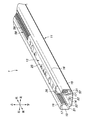
- the electric slide rail 1 has a rail 11 extending in the front-rear direction and a slider 12 slidably engaged with the rail 11.
- the extending direction of the rail 11 is the front-back direction.
- the extending direction of the rail 11 may or may not coincide with the front-rear direction of the vehicle. That is, the extending direction of the rail 11 does not limit the mounting direction in the vehicle.
- the extending direction of the rail 11 coincides with the front-rear direction of the vehicle.
- the slider 12 is provided above the rail 11. Therefore, the rail 11 may be referred to as a lower rail and the slider 12 may be referred to as an upper rail.
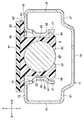
- the rail 11 has a groove-shaped cross section. More specifically, the rail 11 includes rail bottom walls 14 whose surfaces face up and down, left and right rail outer walls 15 which extend upward from left and right edge portions of the rail bottom walls 14 and surfaces face left and right, and left and right rail outer sides.
- Left and right rail upper walls 16 that extend in the directions approaching each other from the upper ends of the walls 15 and face downward, and left and right rail inner walls that extend downward from the inner ends of the left and right rail upper walls 16 respectively. 17 and.
- the left and right rail inner side walls 17 correspond to the first side wall and the second side wall in the claims.
- the rail bottom wall 14, the left and right rail outer walls 15, the left and right rail upper walls 16, and the left and right rail inner walls 17 respectively extend in the front and rear directions.
- the left and right rail outer walls 15 and the left and right rail inner walls 17 extend parallel to each other and perpendicular to the rail bottom wall 14.
- the lower ends of the left and right rail inner side walls 17 are arranged at intervals with respect to the rail bottom wall 14.
- the rail 11 has a rail opening 19 at the top thereof that extends in the front-rear direction.
- the rail openings 19 are defined by the left and right rail inner side walls 17.
- the rail 11 is preferably formed by press-molding a metal plate.
- the left and right edge sides of the rail bottom wall 14 may have stepped portions 21 that are bulged upward.
- the left and right step portions 21 extend in the front-rear direction, and their upper surfaces are formed flat.
- Each of the left and right rail inner side walls 17 is formed with a protrusion 22 that protrudes toward each other and extends in the front-rear direction.
- the cross sections of the left and right protrusions 22 may be formed in an arc shape or a trapezoid shape. It is preferable that each of the protrusions 22 is arranged at an intermediate portion in the vertical direction on the corresponding rail inner side wall 17.
- the upper and lower ends of the left and right rail inner side walls 17 are arranged on the left and right sides of the protrusion 22.
- the slider 12 is disposed at the opening end of the rail opening 19 and has a plate-shaped base portion 25 whose surface faces up and down, and the rail bottom wall 14 side from the left and right side edges of the base portion 25, that is,
- the left and right slider inner side walls 26 extending downward, the left and right slider lower walls 27 extending outward from the lower ends of the left and right slider inner side walls 26, and the left and right slider lower walls 27 extending upward from the left and right outer ends of the left and right slider lower walls 27, respectively.
- the left and right slider inner side walls 26 correspond to the third side wall and the fourth side wall in the claims.
- the base portion 25, the left and right slider inner side walls 26, the left and right slider lower walls 27, and the left and right slider outer side walls 28 extend forward and backward.
- the slider 12 is preferably formed by fastening a plurality of press-formed or roll-formed metal plates to each other.
- the slider 12 includes the base portion 25, the left slider inner wall 26, the left slider lower wall 27, and the left slider outer wall 28, the first piece 12A, the base portion 25, and the right slider.
- the slider 12 is formed by the first piece 12A and the second piece 12B being overlapped and fastened to each other at their respective base portions 25.
- slider 12 may be formed from a single sheet of metal that is press or roll formed.
- the front-rear length of the slider 12 is set shorter than the front-rear length of the rail 11.
- the slider 12 is coupled to the seat cushion 5 at the base portion 25.
- the base portion 25 may be arranged above the left and right rail upper walls 16 or below the left and right rail upper walls 16.
- the left and right slider inner wall surfaces 26 face left and right, and face each other with a distance left and right.
- the left and right slider inner side walls 26 are arranged between the left and right rail inner side walls 17.
- Each slider inner side wall 26 faces the corresponding rail inner side wall 17 on the left and right with a gap.
- Each slider lower wall 27 extends between the rail bottom wall 14 and the left and right lower ends of the corresponding rail 11 inner walls, and extends left and right.
- the outer wall of each slider 12 is arranged between the rail outer side wall 15 and the rail inner side wall 17 corresponding to each other on the left and right.
- a plurality of wheels 31 are rotatably supported on the outer surface side of each slider outer wall 28 in the left-right direction.
- Each wheel 31 has a rotation axis around the left-right direction and is grounded to the rail bottom wall 14.
- each wheel 31 is grounded on the upper surface of the step portion 21 of the rail bottom wall 14.
- the slider 12 can slide smoothly with respect to the rail 11 by being grounded to the rail 11 via the wheels 31.
- the slider 12 is received by the rail 11 and slidably engaged with the rail 11.
- the slider 12 may be supported on the rail 11 via a ball or roller bearing.
- the left and right slider inner side walls 26 are formed with recesses 33 that are recessed toward each other and extend in the front-rear direction.
- a protrusion is formed on the back surface side of the recess 33 of the slider inner wall 26.
- the cross section of the left and right recesses 33 viewed from the front-rear direction may be formed in an arc shape or a trapezoid shape. It is preferable that each recess 33 is arranged at an intermediate portion in the vertical direction on the corresponding slider inner side wall 26. Each recess 33 is arranged at a position facing the corresponding protrusion 22 of the rail 11 on the left and right.
- the slider 12 is formed by the base portion 25 and the left and right slider inner side walls 26 into a groove shape that opens toward the rail bottom wall 14 side, that is, downward.
- a screw assembly 35 and an electric motor 36 are supported on the lower surface of the base portion 25.
- the screw assembly 35 includes screw members 38 and 39 supported by the slider 12 so as to be rotatable around the front-rear direction.
- the electric motor 36 is supported by the slider 12 and rotates the screw members 38 and 39.
- the screw members 38 and 39 include a first screw member 38 and a second screw member 39.
- the screw assembly 35 may have a single screw member.
- the first screw member 38 and the second screw member 39 have threads 38A and 39A on the outer peripheral surface of the intermediate portion in the longitudinal direction.
- the number of threads 38A, 39A may be determined by the size of the electric slide rail 1 and the required strength in the longitudinal direction of the electric slide rail 1. For example, if it is desired to increase the required strength, the number of threads 38A and 39A may be increased.
- the screw assembly 35 includes a gear case 41 that rotatably supports the first screw member 38 and the second screw member 39, and a first bracket 42 that supports the gear case 41 on the slider 12. Have and.
- the gear case 41 is formed in a rectangular parallelepiped box shape that is long in the front-rear direction.
- the gear case 41 rotatably supports the first screw member 38, the second screw member 39, and the drive shaft 43 connected to the rotation shaft 36A of the electric motor 36.
- the first screw member 38, the second screw member 39, and the drive shaft 43 extend in the front-rear direction and are arranged in parallel with each other in the gear case 41.
- the gear case 41 has a box-shaped outer case 41A that forms an outer shell, and a front support member 41B and a rear support member 41C that are supported by the front and rear ends of the outer case 41A.
- the front support member 41B and the rear support member 41C rotate a pair of front and rear first bearing portions 45 that rotatably support the front end and the rear end of the first screw member 38, and the front end and the rear end of the second screw member 39.
- a pair of front and rear second bearing portions 46 that rotatably support the drive shaft 43 and a pair of front and rear third bearing portions 47 that rotatably support the drive shaft 43 are provided.
- the first screw member 38 is arranged along the left side portion of the gear case 41, and the second screw member 39 is arranged along the right side portion of the gear case 41.
- the drive shaft 43 is arranged below the intermediate portion between the first screw member 38 and the second screw member 39.
- the drive shaft 43 has a drive gear 43A inside the gear case 41.
- the first screw member 38 has a first gear 38B that meshes with the drive gear 43A.
- the second screw member 39 has a second gear 39B that meshes with the drive gear 43A.
- Each of the drive gear 43A, the first gear 38B, and the second gear 39B may be a spur gear.
- the gear case 41 has a case opening 48 that is an opening for laterally exposing the first screw member 38 and the second screw member 39.
- the screw thread 38A of the first screw member 38 passes through a case opening 48 formed in the left side portion of the gear case 41 and projects leftward.
- the thread 39 ⁇ /b>A of the second screw member 39 passes through the case opening 48 formed in the right side portion of the gear case 41 and projects rightward.
- the case opening 48 is formed in the outer case 41A.
- the first bracket 42 extends in the front-rear direction and has a first coupling portion 42A provided at the front end and a second coupling portion 42B provided at the rear end.
- the first bracket 42 is joined to the lower surface of the base portion 25 of the slider 12 at the first joining portion 42A and the second joining portion 42B.
- the first bracket 42 has a support portion 42C extending from the first coupling portion 42A to the second coupling portion 42B.
- the first bracket 42 may be an integral metal member including the first joint portion 42A, the second joint portion 42B, and the support portion 42C.
- the support portion 42C has a portion located below the first coupling portion 42A and the second coupling portion 42B. The support portion 42C causes the first bracket 42 to cooperate with the base portion 25 to form a closed structure.
- the gear case 41 is arranged between the base portion 25 of the slider 12 and the support portion 42C.
- the first bracket 42 is formed by bending a metal plate.
- the first coupling portion 42A extends forward from the front portion of the gear case 41, and the second coupling portion 42B extends rearward from the rear portion of the gear case 41.
- the first joint portion 42A and the second joint portion 42B may be fastened to the base portion 25 by fastening members such as screws and rivets.
- the distance between the fastening points of the first coupling portion 42A and the second coupling portion 42B is set longer than the longitudinal length of the gear case 41.
- a second bracket 51 for supporting the electric motor 36 on the base portion 25 of the slider 12 is provided behind the first bracket 42.
- the second bracket 51 has a joining portion 51A joined to the base portion 25 and a support portion 51B extending from the joining portion 51A to the side opposite to the base portion 25, that is, downward.
- the support portion 51B is orthogonal to the coupling portion 51A, and the second bracket 51 is formed in an L shape.
- the electric motor 36 is coupled to the support portion 51B at one end thereof.
- the electric motor 36 is arranged below the coupling portion 51A, and the second bracket 51 supports the end portions of the electric motor 36 on the screw members 38, 39 side in a cantilever manner.
- the rear end of the drive shaft 43 projects rearward from the rear support member 41C of the gear case 41, passes through a through hole formed in the first bracket 42, and extends rearward.
- the rotary shaft 36A of the electric motor 36 is connected to the rear end of the drive shaft 43.
- the rotary shaft 36A and the drive shaft 43 may be coupled by a coupling. Further, the rotary shaft 36A and the drive shaft 43 may have fitting portions that mesh with each other.
- the rotary shaft 36A of the electric motor 36 and the drive shaft 43 are arranged on the same straight line.
- the electric motor 36 is formed in a cylindrical shape and extends in the front-rear direction.
- a speed reducer 40 may be provided between the rotary shaft 36A of the electric motor 36 and the drive shaft 43.
- the speed reducer 40 may be, for example, a planetary gear mechanism.
- the speed reducer 40 may be provided on the surface of the support portion 51B of the second bracket 51 on the side opposite to the electric motor 36. In another embodiment, it may be supported on the rear end surface of the gear case 41.
- the speed reducer 40 has an optional configuration and can be omitted.
- the screw assembly 35, the electric motor 36, the first bracket 42, and the second bracket 51 are arranged below the base portion 25 and between the left and right slider inner side walls 26.
- the left and right slider inner side walls 26 have slider openings 55 that are openings at positions corresponding to the screw assemblies 35.
- the slider opening 55 is formed in the recess 33 of the slider inner wall 26.
- the left part of the thread 38A of the first screw member 38 passes through the case opening 48 on the left side of the gear case 41 and the slider opening 55 of the slider inner side wall 26 on the left side, and projects to the left side of the slider inner side wall 26 on the left side. ..
- the right portion of the screw thread 39A of the second screw member 39 passes through the case opening 48 on the right side of the gear case 41 and the slider opening 55 of the slider inner side wall 26 on the right side to the right side of the slider inner side wall 26 on the right side. It is protruding.
- the rail 11 is formed with screw engaging portions 57 and 58 extending in the front-rear direction and engaging with the screw members 38 and 39.
- FIG. 10 shows only the rail inner side wall 17 in the rail 11.
- the screw engaging portions 57 and 58 are formed on the left rail inner side wall 17, and are formed on the right rail inner side wall 17 and the first screw engaging portion 57 that meshes with the thread 38 ⁇ /b>A of the first screw member 38.
- the second screw engaging portion 58 meshes with the thread 39 ⁇ /b>A of the two-screw member 39.
- the first screw engaging portion 57 and the second screw engaging portion 58 are formed on the corresponding protrusion 22 of the rail inner side wall 17.
- the first screw engaging portion 57 and the second screw engaging portion 58 include a plurality of engaging holes 59 formed in the protrusion 22 side by side in the front-rear direction.
- the first screw member 38 meshes with a plurality of engaging holes 59 of the first screw engaging portion 57 on the left side of the screw thread 38 ⁇ /b>A of the first screw member 38, and rotates in the front-rear direction to rotate the first screw member 38. It moves back and forth with respect to the portion 57.
- the second screw member 39 meshes with the plurality of engaging holes 59 of the second screw engaging portion 58 at the right portion of the thread 39 ⁇ /b>A of the second screw member 39, and rotates around the front-rear direction to move the second screw member 39. It moves back and forth with respect to the screw engaging portion 58.
- the rotation of the electric motor 36 is transmitted to the first screw member 38 and the second screw member 39 via the rotary shaft 36A, the drive shaft 43, the drive gear 43A, the first gear 38B or the second gear 39B.
- the first screw member 38 and the second screw member 39 rotate in the same direction.
- the first screw member 38 and the second screw member 39 rotate, the first screw member 38 and the second screw member 39 move back and forth with respect to the first screw engaging portion 57 and the second screw engaging portion 58,
- the slider 12 moves back and forth with respect to the rail 11.
- the electric slide rail 1 has a power supply device 61 for supplying electric power to the electric motor 36.
- the power feeding device 61 extends back and forth inside the rail 11 and is connected to a power source 68, an electrically insulating plate 63 provided between the rail 11 and the electrically conductive strip 62, and an electric motor 36.
- a conductive contact terminal 64 is provided and is in sliding contact with the conductive strip 62.
- the electric insulating plate 63 is provided on the upper surface of the rail bottom wall 14, and the conductive strip 62 is provided on the upper surface of the electric insulating plate 63.
- the conductive strips 62 are strip-shaped metal plates, are provided in a pair on the left and right, and extend in the front-rear direction.
- the left and right conductive strips 62 are arranged along the left and right side edges of the electric insulating plate 63 extending in the front-rear direction.
- the electric insulating plate 63 has extensions 63A that are bent inwardly and laterally above the corresponding conductive strips 62 on the left and right side edges thereof.
- the extension portions 63A face the corresponding conductive strips 62 on the left and right with a gap therebetween. That is, each extension 63A extends above the corresponding conductive strip 62 on the left and right.
- the extension 63A prevents foreign matter from coming into contact with the conductive strip 62.
- the left and right side edges of the electric insulating plate 63 may respectively have inclined portions 63B that are inclined upward toward the left and right sides.
- the left and right conductive strips 62 may be provided on the upper surface of the inclined portion 63B. In this case, it becomes more difficult for foreign matter to come into contact with the conductive strip 62.
- the contact terminal 64 extends from the electric motor 36 between the extension 63A and the conductive strip 62.
- the contact terminal 64 is biased toward the conductive strip 62 by its elastic force.
- the contact terminal 64 may be, for example, a metal piece having conductivity.
- the electric motor 36 has a left contact terminal 64 that slidably contacts the left conductive strip 62 and a right contact terminal 64 that slidably contacts the right conductive strip 62.
- the electric motor 36 is supplied with power from the power supply 68 by the left and right conductive strips 62 and the left and right contact terminals 64.
- the left and right contact terminals 64 slide forward and backward with respect to the corresponding conductive strips 62, and the left and right contact terminals 64 continue to contact the corresponding conductive strips 62. ..
- the power supply device 61 is connected to the power supply 68 via the control device 66.
- the control device 66 is provided, for example, on the floor 3.
- the control device 66 is an electronic control device, and is connected to the power source 68, the left and right conductive strips 62 of each electric slide rail 1, and the operation switch 67.
- the operation switch 67 has a button corresponding to forward movement and a button corresponding to backward movement.
- the control device 66 adjusts the electric power supplied to each conductive strip 62 based on the signal from the operation switch 67, and controls the rotation direction and the rotation amount of the electric motor 36. Thereby, the operator can operate the electric slide rail 1 by operating the operation switch 67 to move the vehicle seat 2 forward and backward with respect to the floor 3.
- electric motor 36 may be controlled by a wireless signal by a wireless device, independent of the power provided by conductive strip 62.
- Each rail 11 of the left and right electric slide rails 1 is connected to the floor 3 of the vehicle via a bracket or directly.
- Each rail 11 may be received in a rail groove 4 formed in the floor 3.
- the upper surface of the rail upper wall 16 of the rail 11 may be arranged on the same plane as the upper surface of the floor 3.
- Each slider 12 of the left and right electric slide rails 1 is coupled to the seat cushion 5.
- the sliders 12 of the left and right electric slide rails 1 may be connected to each other by a connecting member.
- the electric slide rail 1 since the electric motor 36 and the screw assembly 35 are fixed to the slider 12, the first screw member 38 for the first screw engaging portion 57 and the second screw engaging portion 58, The fall of the second screw member 39 is suppressed. Therefore, the first screw member 38 can be engaged with the first screw engaging portion 57 at an appropriate angle, and the rotation of the first screw member 38 can be smoothly performed. The same applies to the second screw member 39. As a result, it is possible to provide the electric slide rail 1 that can operate smoothly. Further, since the electric motor 36 is attached to the slider 12 that is received by the rail 11, the outer shape of the electric slide rail 1 can be downsized.
- the electric motor 36 is arranged inside the slider 12, the distance between the electric motor 36 and the screw assembly 35 can be shortened, and the drive shaft 43 connecting the electric motor 36 and the screw assembly 35 can be shortened. be able to. As a result, the bending of the drive shaft 43 is suppressed, and the screw assembly 35 can rotate smoothly.
- the screw assembly 35 Since the screw assembly 35 has the first screw member 38 and the second screw member 39, the screw assembly 35 is small in size while engaging with both the first screw engaging portion 57 and the second screw engaging portion 58. It becomes possible. Further, since the direction of the reaction force that the first screw member 38 receives from the first screw engagement portion 57 and the direction of the reaction force that the second screw member 39 receives from the second screw engagement portion 58 are opposite directions, The first screw member 38 and the first screw engaging portion 57 are securely engaged with each other, and the second screw member 39 and the second screw engaging portion 58 are surely engaged with each other.
- first screw member 38 and the second screw member 39 form the screw assembly 35 together with the gear case 41 and the first bracket 42, they can be easily assembled to the slider 12.
- a power supply device 81 which is a modified example of the power supply device 61 will be described below.
- the power supply device 81 enables the wire harness to be delivered according to the position of the slider 12 while suppressing unnecessary movement of the wire harness with respect to the floor 3.
- the wire harness is used for power supply and communication.
- the power feeding device 81 also functions as a cover that closes the opening of the rail 11. As shown in FIGS. 11 to 13, the power feeding device 81 stores the power line 82 connected to the power source 68 via the control device 66, the cover piece 83 attached to the power line 82, and the power line 82 and the cover piece 83. And a storage case 84 for storing.
- the power line 82 is a wire harness whose outer peripheral portion is covered with an electric insulating material.
- the storage case 84 has a storage chamber 86 defined therein, an inlet hole 87 connecting the storage chamber 86 and the outside, and a fixing portion 88 arranged in the storage chamber 86 and fixing one end of the power line 82. ..
- the storage case 84 is formed in a flat box shape.
- the inlet hole 87 of the storage case 84 is provided on the side portion of the storage case 84 and is connected to the front end or the rear end of the rail 11.
- the inlet hole 87 is connected to the rear end of the rail 11.
- the inlet hole 87 is provided in the rear portion of the left or right side edge of the storage case 84, and opens toward the front.
- the fixing portion 88 is a through hole provided in the bottom portion of the storage case 84.
- the cover piece 83 is not attached to one end side of the power line 82, and the power line 82 is fixed by being inserted into the fixing portion 88.
- the power line 82 passes through the fixed portion 88, extends to the outside of the storage case 84, and is connected to the control device 66.
- the power line 82 is connected to the electric motor 36 from the fixing portion 88 through the storage chamber 86, the inlet hole 87, and the rail 11 in order.
- An electric connector connected to the electric motor 36 may be provided inside the slider 12, and the power line 82 may be connected to the electric connector.
- a plurality of cover pieces 83 are coupled to the outer peripheral portion of the power line 82. As shown in FIG. 13, the cover piece 83 has an upper plate 91 and a pair of support pieces 92 protruding downward from the upper plate 91.
- the cover piece 83 is preferably made of resin, for example.
- the pair of support pieces 92 sandwich the power line 82 between them.
- each support piece 92 is provided with a first locking claw 93 that protrudes in a direction toward each other.
- the power line 82 is maintained between the pair of support pieces 92 by the pair of first locking claws 93 locking the power line 82.
- the cover piece 83 When the cover piece 83 is located in the rail 11, the left and right side edges of the upper plate 91 are placed on the upper surfaces of the left and right rail upper walls 16, and the pair of support pieces 92 are arranged between the left and right rail inner side walls 17. To be done.
- a second locking claw 94 is provided at the lower end of each support piece 92 so as to project away from each other. By contacting the pair of second locking claws 94 with the corresponding rail inner side wall 17, the vertical position of the cover piece 83 with respect to the rail 11 is determined. In the present embodiment, the pair of second locking claws 94 are in contact with the lower portions of the projections 22 of the rail inner side wall 17. In another embodiment, the pair of second locking claws 94 may abut the lower edge of the rail inner wall 17.
- the upper plates 91 of the adjacent cover pieces 83 have portions that overlap each other in the vertical direction.
- the upper plates 91 of the adjacent cover pieces 83 are rotatably connected within a predetermined range about a pivot 96 extending vertically.
- the cover piece 83 whose rotation range is restricted on the power line 82 By mounting the cover piece 83 whose rotation range is restricted on the power line 82, the bending of the power line 82 is restricted within a predetermined range.
- One of the plurality of cover pieces 83 arranged closest to the electric motor 36 is coupled to the rear end of the slider 12.
- the plurality of cover pieces 83 cover the rail opening 19 of the rail 11 on the rear side of the slider 12. Further, the plurality of cover pieces 83 hide the power line 82.
- a guide wall 97 that guides the moving direction of the cover piece 83 is provided inside the storage case 84.
- the guide wall 97 is curved in a semicircle in a plan view.
- the guide wall 97 slides on the side portion of the cover piece 83 to smoothly bend the cover piece 83 moving rearward in the storage chamber 86 and guide the cover piece 83 to the front portion of the storage chamber 86.
- the upper edge of the entrance hole 87 of the storage case 84 is located above the upper surface of the rail 11.
- a guide slope (not shown) for guiding the upper plate 91 of the cover piece 83 in the inlet hole 87 onto the upper surface of the rail 11 is provided on the side of the inlet hole 87.
- the present invention is not limited to the above embodiments and can be widely modified and implemented.
- the electric slide rail 1 may be arranged on an object such that the rail 11 extends in the left-right direction or the vertical direction.
- the shapes of the rail 11 and the slider 12 can be appropriately changed according to the purpose.
- an example in which the present invention is applied to a vehicle seat has been described, but the vehicle seat according to the present invention can also be applied to various seats for aircraft, railroads, and the like.
- the drive gear 43A may be provided in a front-rear pair, and the first gear 38B and the second gear 39B may be provided in a front-rear pair corresponding to the drive gear 43A.
- the contact terminal 64 may be connected to another electric device provided in the vehicle seat 2 in addition to the electric motor 36 to supply electric power to the electric device.
- a plurality of sliders 12 may be arranged on one rail 11. That is, a seat including a plurality of seat cushions 5 independent of each other may be arranged on one rail 11. In that case, a conductive strip 62 may be provided corresponding to each sheet.
- the slider 12 may have a connecting portion 29 protruding upward from the base portion 25.
- the connecting portion 29 is formed in a plate shape, and its surface faces left and right.
- the slider 12 may be coupled to the seat cushion 5 at the connecting portion 29.
- the slider 12 includes a connecting portion 29, a base portion 25, a slider inner wall 26 on the left side, a slider lower wall 27 on the left side, and a slider outer wall 28 on the left side.
- the wall 26, the slider lower wall 27 on the right side, and the second piece 12B constituting the slider outer side wall 28 on the right side.
- the first piece 12A and the second piece 12B are preferably overlapped with each other at their connecting portions 29 and fastened together to form the slider 12.
Landscapes
- Engineering & Computer Science (AREA)
- Aviation & Aerospace Engineering (AREA)
- Transportation (AREA)
- Mechanical Engineering (AREA)
- Seats For Vehicles (AREA)
Abstract
Description
2 :乗物用シート
3 :フロア
5 :シートクッション
11 :レール
12 :スライダ
17 :レール内側壁
22 :突部
25 :ベース部
26 :スライダ内側壁
35 :ねじアセンブリ
36 :電動モータ
36A :回転軸
38 :第1ねじ部材
38A :ねじ山
38B :第1ギヤ
39 :第2ねじ部材
39A :ねじ山
39B :第2ギヤ
41 :ギヤケース
42 :第1ブラケット
42A :第1結合部
42B :第2結合部
42C :支持部
43 :駆動軸
43A :駆動ギヤ
45 :第1軸受部
46 :第2軸受部
47 :第3軸受部
51 :第2ブラケット
51A :結合部
51B :支持部
57 :第1ねじ係合部
58 :第2ねじ係合部
59 :係合孔
61 :給電装置
62 :導電性ストリップ
63 :電気絶縁板
63A :延長部
64 :接触端子
Claims (15)
- 電動スライドレールであって、
溝形の断面を有し、前後方向に延在するレールと、
前記レールに受容され、かつ前記レールにスライド可能に係合するスライダと、
前記前後方向周りに回転可能に前記スライダに支持されたねじ部材を含むねじアセンブリと、
前記スライダに支持され、前記ねじ部材を回転させる電動モータと、
前記前後方向に延在し、前記ねじ部材と係合するように前記レールに形成されたねじ係合部とを有する電動スライドレール。 - 前記レールは、互いに対向した第1側壁及び第2側壁を有し、
前記ねじ係合部は、前記第1側壁に形成された第1ねじ係合部と、前記第2側壁に形成された第2ねじ係合部とを有し、
前記ねじ部材は、前記第1ねじ係合部及び前記第2ねじ係合部間にて互いに並列に配置された、前記第1ねじ係合部に係合する第1ねじ部材及び前記第2ねじ係合部に係合する第2ねじ部材を有する請求項1に記載の電動スライドレール。 - 前記ねじアセンブリは、前記第1ねじ部材及び前記第2ねじ部材を回転可能に支持するギヤケース及び前記ギヤケースを前記スライダに支持するための第1ブラケットを有し、
前記ギヤケースは、前記第1ねじ部材及び前記第2ねじ部材を側方に露出させるための開口を有する請求項2に記載の電動スライドレール。 - 前記第1ブラケットは、前記ギヤケースの前部から前方に延出する第1結合部と、前記ギヤケースの後部から後方に延出する第2結合部とを有し、前記第1結合部及び前記第2結合部において前記スライダに結合されている請求項3に記載の電動スライドレール。
- 前記第1ブラケットは、前記第1結合部から前記第2結合部に延びる支持部を含む一体的な金属製の部材をなし、前記ギヤケースは、前記スライダと前記支持部との間に配置されている請求項4に記載の電動スライドレール。
- 前記スライダにおける前記第1ブラケットの前方又は後方に結合された、前記電動モータを支持するための第2ブラケットを更に有し、
前記第2ブラケットは、前記電動モータの前記ねじ部材側の端部を片持ち支持する請求項5に記載の電動スライドレール。 - 前記スライダは、ベース部と、前記ベース部から前記レールの底部側に延びる第3側壁及び第4側壁とを有して溝形に形成され、
前記第3側壁は前記第1側壁と対向し、
前記第4側壁は前記第2側壁と対向し、
前記第2ブラケットは前記ベース部に結合され、前記電動モータは前記第3側壁と前記第4側壁との間に配置されている請求項6に記載の電動スライドレール。 - 前記第1ねじ部材は、前記第3側壁に形成された開口を通過して前記第1ねじ係合部に係合し、
前記第2ねじ部材は、前記第4側壁に形成された開口を通過して前記第2ねじ係合部に係合している請求項7に記載の電動スライドレール。 - 前記ギヤケースは、前記第1ねじ部材の前端及び後端を回転可能に支持する前後一対の第1軸受部と、前記第2ねじ部材の前端及び後端を回転可能に支持する前後一対の第2軸受部と、前記電動モータの回転軸に連結した駆動軸を回転可能に支持する前後一対の第3軸受部とを有し、
前記駆動軸は、駆動ギヤを有し、
前記第1ねじ部材は、前記駆動ギヤにそれぞれ噛み合う第1ギヤを有し、
前記第2ねじ部材は、前記駆動ギヤにそれぞれ噛み合う第2ギヤを有する請求項3~請求項8のいずれか1つの項に記載の電動スライドレール。 - 前記電動モータの前記回転軸と前記駆動軸とは、減速機を介して互いに接続されている請求項9に記載の電動スライドレール。
- 前記第1側壁及び前記第2側壁には、互いに近づく方向に突出すると共に、前後方向に延びた突部が形成され、
前記ねじ係合部は、前記突部に前後方向に並んで形成された複数の係合孔を含む請求項2~請求項10のいずれか1つの項に記載の電動スライドレール。 - 前記レールの内部には、前後に延び、電源に接続される導電性ストリップと、前記レールと前記導電性ストリップとの間に設けられた電気絶縁板とが設けられ、
前記電動モータは、前記導電性ストリップに摺接する導電性の接触端子を有する請求項1~請求項11のいずれか1つの項に記載の電動スライドレール。 - 前記電気絶縁板は、その側縁に内方かつ前記導電性ストリップの上方に折り曲げられ、前記導電性ストリップに対して隙間を介して対向する延長部を有し、
前記接触端子は、前記延長部と前記導電性ストリップとの間に延びる請求項12に記載の電動スライドレール。 - 請求項1~請求項13のいずれか1つの項に記載の電動スライドレールを備えた乗物用シートであって、
前記レールが乗物のフロアに結合され、
前記スライダがシートクッションに結合されている乗物用シート。 - 前記レールは、前記フロアに設けられたレール溝に受容されている請求項14に記載の乗物用シート。
Priority Applications (11)
| Application Number | Priority Date | Filing Date | Title |
|---|---|---|---|
| CN201980087566.3A CN113226840B (zh) | 2019-01-03 | 2019-12-26 | 电动滑轨及具有电动滑轨的交通工具用座椅 |
| US17/420,518 US12017561B2 (en) | 2019-01-03 | 2019-12-26 | Electrically powered slide rail and vehicle seat provided with electrically powered slide rail |
| EP19907456.8A EP3907104B1 (en) | 2019-01-03 | 2019-12-26 | Electrically powered slide rail and vehicle seat provided with electrically powered slide rail |
| JP2020563871A JP7436858B2 (ja) | 2019-01-03 | 2019-12-26 | 電動スライドレール及び電動スライドレールを備えた乗物用シート |
| CN202310788943.4A CN116653717A (zh) | 2019-01-03 | 2019-12-26 | 电动滑轨及具有电动滑轨的交通工具用座椅 |
| US17/702,916 US12162382B2 (en) | 2019-01-03 | 2022-03-24 | Electrically powered slide rail and vehicle seat provided with electrically powered slide rail |
| US17/702,867 US12168402B2 (en) | 2019-01-03 | 2022-03-24 | Electrically powered slide rail and vehicle seat provided with electrically powered slide rail |
| US17/702,964 US12168403B2 (en) | 2019-01-03 | 2022-03-24 | Electrically powered slide rail and vehicle seat provided with electrically powered slide rail |
| JP2024014266A JP7755191B2 (ja) | 2019-01-03 | 2024-02-01 | 電動スライドレール及び電動スライドレールを備えた乗物用シート |
| US18/949,436 US20250074261A1 (en) | 2019-01-03 | 2024-11-15 | Electrically Powered Slide Rail and Vehicle Seat Provided with Electrically Powered Slide Rail |
| JP2025163768A JP2025184996A (ja) | 2019-01-03 | 2025-09-30 | 電動スライドレール及び電動スライドレールの製造方法 |
Applications Claiming Priority (4)
| Application Number | Priority Date | Filing Date | Title |
|---|---|---|---|
| US201962787913P | 2019-01-03 | 2019-01-03 | |
| US201962787908P | 2019-01-03 | 2019-01-03 | |
| US62/787,908 | 2019-01-03 | ||
| US62/787,913 | 2019-01-03 |
Related Child Applications (4)
| Application Number | Title | Priority Date | Filing Date |
|---|---|---|---|
| US17/420,518 A-371-Of-International US12017561B2 (en) | 2019-01-03 | 2019-12-26 | Electrically powered slide rail and vehicle seat provided with electrically powered slide rail |
| US17/702,964 Continuation US12168403B2 (en) | 2019-01-03 | 2022-03-24 | Electrically powered slide rail and vehicle seat provided with electrically powered slide rail |
| US17/702,916 Continuation US12162382B2 (en) | 2019-01-03 | 2022-03-24 | Electrically powered slide rail and vehicle seat provided with electrically powered slide rail |
| US17/702,867 Continuation US12168402B2 (en) | 2019-01-03 | 2022-03-24 | Electrically powered slide rail and vehicle seat provided with electrically powered slide rail |
Publications (1)
| Publication Number | Publication Date |
|---|---|
| WO2020141600A1 true WO2020141600A1 (ja) | 2020-07-09 |
Family
ID=71407194
Family Applications (1)
| Application Number | Title | Priority Date | Filing Date |
|---|---|---|---|
| PCT/JP2019/051180 Ceased WO2020141600A1 (ja) | 2019-01-03 | 2019-12-26 | 電動スライドレール及び電動スライドレールを備えた乗物用シート |
Country Status (5)
| Country | Link |
|---|---|
| US (5) | US12017561B2 (ja) |
| EP (1) | EP3907104B1 (ja) |
| JP (3) | JP7436858B2 (ja) |
| CN (2) | CN113226840B (ja) |
| WO (1) | WO2020141600A1 (ja) |
Cited By (7)
| Publication number | Priority date | Publication date | Assignee | Title |
|---|---|---|---|---|
| WO2022090805A1 (en) * | 2020-10-30 | 2022-05-05 | Ts Tech Co. Ltd. | Seat rail assembly |
| WO2023127177A1 (ja) | 2021-12-27 | 2023-07-06 | テイ・エス テック株式会社 | 車両用シート |
| WO2023219166A1 (ja) * | 2022-05-13 | 2023-11-16 | テイ・エス テック株式会社 | 乗物用シート |
| JP2024007444A (ja) * | 2022-06-30 | 2024-01-18 | テイ・エス テック株式会社 | 電動スライドレール及び電動スライドレールを備えた乗物用シート |
| WO2024185598A1 (ja) | 2023-03-03 | 2024-09-12 | テイ・エス テック株式会社 | 電動スライドレール、電動スライドレールを備えた乗物用シート、及び電動スライドレールの製造方法 |
| WO2025028618A1 (ja) * | 2023-08-02 | 2025-02-06 | テイ・エス テック株式会社 | 電動スライドレール及び電動スライドレールの製造方法 |
| KR20250123288A (ko) * | 2024-02-07 | 2025-08-18 | 대원정밀공업(주) | 차량용 롱슬라이드 레일 시스템 |
Families Citing this family (8)
| Publication number | Priority date | Publication date | Assignee | Title |
|---|---|---|---|---|
| US12071044B2 (en) * | 2019-03-14 | 2024-08-27 | Magna Seating Inc. | Long rail assembly with internal power driving system |
| DE102021200454B4 (de) * | 2021-01-19 | 2024-03-14 | Brose Fahrzeugteile SE & Co. Kommanditgesellschaft, Coburg | Baugruppe mit einer mit einer Bodenbaugruppe verbundenen Führungsschiene |
| JP7654816B2 (ja) * | 2021-10-26 | 2025-04-01 | テイ・エス テック株式会社 | スライドロック装置及びスライド装置の組み立て方法 |
| WO2023228976A1 (ja) * | 2022-05-25 | 2023-11-30 | テイ・エス テック株式会社 | 給電レール及び車両用シート |
| CN115709672B (zh) * | 2022-12-07 | 2025-06-24 | 江苏忠明祥和精工股份有限公司 | 一种汽车座椅的自动滑轨 |
| JP2024148143A (ja) * | 2023-04-04 | 2024-10-17 | テイ・エス テック株式会社 | 電動スライドレール、電動スライドレールを備えた乗物用シート、及び電動スライドレールの製造方法 |
| CN117325725A (zh) * | 2023-09-27 | 2024-01-02 | 恺博(常熟)座椅机械部件有限公司 | 一种齿轮箱直驱滑轨 |
| US20250187499A1 (en) * | 2023-12-07 | 2025-06-12 | Lear Corporation | Track assembly |
Citations (4)
| Publication number | Priority date | Publication date | Assignee | Title |
|---|---|---|---|---|
| JPH04310437A (ja) * | 1991-04-05 | 1992-11-02 | Imasen Denki Seisakusho:Kk | 車両用シートの電動スライド装置 |
| JPH0741120U (ja) * | 1993-12-28 | 1995-07-21 | 株式会社今仙電機製作所 | パワースライド装置 |
| JPH10217810A (ja) * | 1997-02-07 | 1998-08-18 | Ikeda Bussan Co Ltd | 自動車シートのパワースライド装置 |
| JP2003063284A (ja) * | 2001-08-24 | 2003-03-05 | Aisin Seiki Co Ltd | パワースライド機構 |
Family Cites Families (38)
| Publication number | Priority date | Publication date | Assignee | Title |
|---|---|---|---|---|
| US4015812A (en) * | 1975-10-28 | 1977-04-05 | International Telephone And Telegraph Corporation | Seat adjustment mechanism |
| US4448381A (en) * | 1980-01-14 | 1984-05-15 | International Telephone And Telegraph Corporation | Motor mount structure for vehicle seat adjustment apparatus |
| JPH068915Y2 (ja) * | 1989-02-27 | 1994-03-09 | 富士機工株式会社 | 車両用座席上下調節装置 |
| JP2780320B2 (ja) * | 1989-03-31 | 1998-07-30 | アイシン精機株式会社 | 自動車用パワーシートスライド装置 |
| US5447352A (en) * | 1992-06-22 | 1995-09-05 | Aisin Seiki Kabushiki Kaisha | Seat slide mechanism for vehicles |
| JP4096382B2 (ja) * | 1997-09-05 | 2008-06-04 | トヨタ紡織株式会社 | パワーシートスライド装置 |
| JP2003065419A (ja) | 2001-08-24 | 2003-03-05 | Aisin Seiki Co Ltd | スライド機構及びシート用のパワースライド装置 |
| JP2003063285A (ja) | 2001-08-24 | 2003-03-05 | Aisin Seiki Co Ltd | パワースライド装置 |
| DE10238750A1 (de) | 2001-08-24 | 2003-03-13 | Aisin Seiki | Angetriebene Schlittenvorrichtung für einen Sitz |
| FR2837148B1 (fr) * | 2002-03-18 | 2004-07-02 | Faurecia Sieges Automobile | Mecanisme de reglage pour glissiere de siege de vehicule automobile ainsi que glissiere et siege equipes d'un tel mecanisme |
| JP4419518B2 (ja) * | 2003-10-30 | 2010-02-24 | アイシン精機株式会社 | シートスライド装置 |
| JP4380406B2 (ja) * | 2004-04-26 | 2009-12-09 | アイシン精機株式会社 | 車両用シート装置 |
| CA2505207A1 (en) * | 2004-05-13 | 2005-11-13 | Faurecia Automotive Seating Canada Limited | Horizontal drive apparatus for use with a vehicle seat slide |
| EP1863670B1 (en) * | 2005-02-02 | 2014-04-02 | Johnson Controls Technology Company | Vehicle seat track system |
| FR2882974B1 (fr) * | 2005-03-14 | 2008-11-07 | Faurecia Sieges Automobile | Mecanisme de reglage a vis, glissiere comportant un tel mecanisme de reglage et siege comportant une telle glissiere |
| JP4661316B2 (ja) * | 2005-04-08 | 2011-03-30 | アイシン精機株式会社 | 車両用パワーシートスライド装置 |
| DE202005013714U1 (de) * | 2005-05-10 | 2005-12-22 | Allsafe Jungfalk Gmbh & Co. Kg | Vorrichtung zum zeitweiligen Verbinden einer Sitzeinrichtung oder eines dergl. bewegbaren Gegenstandes mit einer Auflagefläche |
| JP2010172116A (ja) * | 2009-01-23 | 2010-08-05 | Yazaki Corp | ハーネス巻取式給電装置 |
| JP5248436B2 (ja) * | 2009-07-22 | 2013-07-31 | 矢崎総業株式会社 | ワイヤハーネス配索装置 |
| JP5451274B2 (ja) * | 2009-09-11 | 2014-03-26 | 矢崎総業株式会社 | ワイヤハーネス配索装置 |
| EP2305512B1 (en) * | 2009-10-05 | 2014-01-01 | Delta Kogyo Co., Ltd. | Seat slide structure for vehicle |
| JP5662056B2 (ja) * | 2010-05-24 | 2015-01-28 | シロキ工業株式会社 | パワースライド装置 |
| CN104011434B (zh) * | 2012-01-24 | 2016-09-07 | 白木工业株式会社 | 齿轮箱支架和电动座椅滑动装置 |
| JP5845949B2 (ja) * | 2012-02-14 | 2016-01-20 | アイシン精機株式会社 | 車両用シートスライド装置 |
| JP6015512B2 (ja) * | 2013-03-22 | 2016-10-26 | 住友電装株式会社 | スライドシート用のワイヤハーネス配索装置 |
| JP6140545B2 (ja) * | 2013-06-20 | 2017-05-31 | トヨタ紡織株式会社 | 乗物用シートのパワースライド装置 |
| JP6253937B2 (ja) * | 2013-09-30 | 2017-12-27 | トヨタ紡織株式会社 | 乗物用シート |
| JP6456253B2 (ja) * | 2014-08-11 | 2019-01-23 | 株式会社Tf−Metal | シートスライド装置 |
| JP6284856B2 (ja) * | 2014-08-28 | 2018-02-28 | トヨタ紡織株式会社 | 乗物用シートのスライドレール |
| CA2952128C (en) * | 2015-12-18 | 2022-03-08 | Magna Seating Inc. | Quick adjust power adjuster with split nut for automotive seat |
| JP2017226356A (ja) * | 2016-06-23 | 2017-12-28 | アイシン精機株式会社 | 車両用シートスライド装置 |
| JP2018016238A (ja) * | 2016-07-29 | 2018-02-01 | アイシン精機株式会社 | 車両用シートスライド装置 |
| US11273506B2 (en) * | 2016-09-08 | 2022-03-15 | Fisher & Company, Incorporated | Open architecture power length adjuster assembly for a vehicle seat and method of manufacturing the same |
| US10486554B2 (en) * | 2016-09-08 | 2019-11-26 | Fisher & Company, Inc. | Power seat length adjuster assembly and method of manufacture |
| JP6756948B2 (ja) * | 2016-09-26 | 2020-09-16 | デルタ工業株式会社 | パワーシートスライド装置 |
| US20180304777A1 (en) * | 2017-04-25 | 2018-10-25 | Toyota Boshoku Kabushiki Kaisha | Sliding device |
| JP2018193007A (ja) * | 2017-05-19 | 2018-12-06 | トヨタ紡織株式会社 | スライド装置 |
| JP2019098916A (ja) * | 2017-12-01 | 2019-06-24 | トヨタ紡織株式会社 | スライド装置 |
-
2019
- 2019-12-26 CN CN201980087566.3A patent/CN113226840B/zh active Active
- 2019-12-26 US US17/420,518 patent/US12017561B2/en active Active
- 2019-12-26 EP EP19907456.8A patent/EP3907104B1/en active Active
- 2019-12-26 JP JP2020563871A patent/JP7436858B2/ja active Active
- 2019-12-26 WO PCT/JP2019/051180 patent/WO2020141600A1/ja not_active Ceased
- 2019-12-26 CN CN202310788943.4A patent/CN116653717A/zh active Pending
-
2022
- 2022-03-24 US US17/702,916 patent/US12162382B2/en active Active
- 2022-03-24 US US17/702,867 patent/US12168402B2/en active Active
- 2022-03-24 US US17/702,964 patent/US12168403B2/en active Active
-
2024
- 2024-02-01 JP JP2024014266A patent/JP7755191B2/ja active Active
- 2024-11-15 US US18/949,436 patent/US20250074261A1/en active Pending
-
2025
- 2025-09-30 JP JP2025163768A patent/JP2025184996A/ja active Pending
Patent Citations (4)
| Publication number | Priority date | Publication date | Assignee | Title |
|---|---|---|---|---|
| JPH04310437A (ja) * | 1991-04-05 | 1992-11-02 | Imasen Denki Seisakusho:Kk | 車両用シートの電動スライド装置 |
| JPH0741120U (ja) * | 1993-12-28 | 1995-07-21 | 株式会社今仙電機製作所 | パワースライド装置 |
| JPH10217810A (ja) * | 1997-02-07 | 1998-08-18 | Ikeda Bussan Co Ltd | 自動車シートのパワースライド装置 |
| JP2003063284A (ja) * | 2001-08-24 | 2003-03-05 | Aisin Seiki Co Ltd | パワースライド機構 |
Cited By (12)
| Publication number | Priority date | Publication date | Assignee | Title |
|---|---|---|---|---|
| WO2022090805A1 (en) * | 2020-10-30 | 2022-05-05 | Ts Tech Co. Ltd. | Seat rail assembly |
| US12139048B2 (en) | 2020-10-30 | 2024-11-12 | Ts Tech Co., Ltd. | Seat rail assembly |
| US12145478B2 (en) | 2020-10-30 | 2024-11-19 | Ts Tech Co., Ltd. | Seat rail assembly |
| US12179637B2 (en) | 2020-10-30 | 2024-12-31 | Ts Tech Co., Ltd. | Seat rail assembly |
| WO2023127177A1 (ja) | 2021-12-27 | 2023-07-06 | テイ・エス テック株式会社 | 車両用シート |
| WO2023219166A1 (ja) * | 2022-05-13 | 2023-11-16 | テイ・エス テック株式会社 | 乗物用シート |
| JP2024007444A (ja) * | 2022-06-30 | 2024-01-18 | テイ・エス テック株式会社 | 電動スライドレール及び電動スライドレールを備えた乗物用シート |
| JP7684589B2 (ja) | 2022-06-30 | 2025-05-28 | テイ・エス テック株式会社 | 電動スライドレール及び電動スライドレールを備えた乗物用シート |
| WO2024185598A1 (ja) | 2023-03-03 | 2024-09-12 | テイ・エス テック株式会社 | 電動スライドレール、電動スライドレールを備えた乗物用シート、及び電動スライドレールの製造方法 |
| WO2025028618A1 (ja) * | 2023-08-02 | 2025-02-06 | テイ・エス テック株式会社 | 電動スライドレール及び電動スライドレールの製造方法 |
| KR20250123288A (ko) * | 2024-02-07 | 2025-08-18 | 대원정밀공업(주) | 차량용 롱슬라이드 레일 시스템 |
| KR102880021B1 (ko) | 2024-02-07 | 2025-11-03 | 대원정밀공업(주) | 차량용 롱슬라이드 레일 시스템 |
Also Published As
| Publication number | Publication date |
|---|---|
| JPWO2020141600A1 (ja) | 2021-11-18 |
| JP2025184996A (ja) | 2025-12-18 |
| US20220212569A1 (en) | 2022-07-07 |
| JP2024032946A (ja) | 2024-03-12 |
| EP3907104A4 (en) | 2022-08-17 |
| US20220212570A1 (en) | 2022-07-07 |
| US20220080862A1 (en) | 2022-03-17 |
| JP7436858B2 (ja) | 2024-02-22 |
| EP3907104A1 (en) | 2021-11-10 |
| CN113226840B (zh) | 2023-07-21 |
| US12162382B2 (en) | 2024-12-10 |
| US12017561B2 (en) | 2024-06-25 |
| US12168402B2 (en) | 2024-12-17 |
| EP3907104B1 (en) | 2025-08-20 |
| US12168403B2 (en) | 2024-12-17 |
| JP7755191B2 (ja) | 2025-10-16 |
| US20220289078A1 (en) | 2022-09-15 |
| US20250074261A1 (en) | 2025-03-06 |
| CN113226840A (zh) | 2021-08-06 |
| CN116653717A (zh) | 2023-08-29 |
Similar Documents
| Publication | Publication Date | Title |
|---|---|---|
| JP7436858B2 (ja) | 電動スライドレール及び電動スライドレールを備えた乗物用シート | |
| JP5029785B2 (ja) | 車両用シートスライド装置 | |
| JP6032125B2 (ja) | スライドシート用のワイヤハーネス配索装置 | |
| JP3814270B2 (ja) | 車両用自動開閉装置 | |
| CN101746288A (zh) | 座椅的滑动结构 | |
| KR101987006B1 (ko) | 자동차의 전동식 슬라이딩 콘솔 | |
| US20250353407A1 (en) | Slide lock device and assembly method for slide device | |
| JP2008126732A (ja) | 駆動装置 | |
| WO2023219166A1 (ja) | 乗物用シート | |
| JP2014227050A (ja) | スライドシート用のワイヤハーネス配索構造 | |
| JP2009090942A (ja) | 車両用シートのパワースライド装置におけるアッパレール連結装置 | |
| JP2007336613A (ja) | スライダのレール脱落防止構造 | |
| WO2024185598A1 (ja) | 電動スライドレール、電動スライドレールを備えた乗物用シート、及び電動スライドレールの製造方法 | |
| JP2023172340A (ja) | 給電レール構造 | |
| US20250333012A1 (en) | Power supply rail and vehicle seat | |
| JP5939182B2 (ja) | スライドシート用のワイヤハーネス配索構造 | |
| JP2024125186A (ja) | スライドレール及びスライドレールの製造方法 | |
| CN223173988U (zh) | 一种滑轨总成及车辆 | |
| JP2023174517A (ja) | 給電レール及び車両用シート | |
| JP2014184838A (ja) | スライドシート用のワイヤハーネス配索装置 | |
| WO2025211425A1 (ja) | スライドロック装置及びスライド装置の組立方法 | |
| JP6027466B2 (ja) | 電動リモートコントロールミラー装置 | |
| JP3780276B2 (ja) | 車両用自動開閉装置 | |
| KR20230094771A (ko) | 차량용 시트 슬라이딩 장치 | |
| JP2017095031A (ja) | ワイヤーハーネス配索装置 |
Legal Events
| Date | Code | Title | Description |
|---|---|---|---|
| 121 | Ep: the epo has been informed by wipo that ep was designated in this application |
Ref document number: 19907456 Country of ref document: EP Kind code of ref document: A1 |
|
| ENP | Entry into the national phase |
Ref document number: 2020563871 Country of ref document: JP Kind code of ref document: A |
|
| NENP | Non-entry into the national phase |
Ref country code: DE |
|
| ENP | Entry into the national phase |
Ref document number: 2019907456 Country of ref document: EP Effective date: 20210803 |
|
| WWG | Wipo information: grant in national office |
Ref document number: 2019907456 Country of ref document: EP |