WO2020084936A1 - 無段変速機 - Google Patents
無段変速機 Download PDFInfo
- Publication number
- WO2020084936A1 WO2020084936A1 PCT/JP2019/035330 JP2019035330W WO2020084936A1 WO 2020084936 A1 WO2020084936 A1 WO 2020084936A1 JP 2019035330 W JP2019035330 W JP 2019035330W WO 2020084936 A1 WO2020084936 A1 WO 2020084936A1
- Authority
- WO
- WIPO (PCT)
- Prior art keywords
- pulley
- cylinder
- rear cylinder
- rotation axis
- groove
- Prior art date
- Legal status (The legal status is an assumption and is not a legal conclusion. Google has not performed a legal analysis and makes no representation as to the accuracy of the status listed.)
- Ceased
Links
Images


Classifications
-
- F—MECHANICAL ENGINEERING; LIGHTING; HEATING; WEAPONS; BLASTING
- F16—ENGINEERING ELEMENTS AND UNITS; GENERAL MEASURES FOR PRODUCING AND MAINTAINING EFFECTIVE FUNCTIONING OF MACHINES OR INSTALLATIONS; THERMAL INSULATION IN GENERAL
- F16H—GEARING
- F16H9/00—Gearings for conveying rotary motion with variable gear ratio, or for reversing rotary motion, by endless flexible members
- F16H9/02—Gearings for conveying rotary motion with variable gear ratio, or for reversing rotary motion, by endless flexible members without members having orbital motion
- F16H9/04—Gearings for conveying rotary motion with variable gear ratio, or for reversing rotary motion, by endless flexible members without members having orbital motion using belts, V-belts, or ropes
- F16H9/12—Gearings for conveying rotary motion with variable gear ratio, or for reversing rotary motion, by endless flexible members without members having orbital motion using belts, V-belts, or ropes engaging a pulley built-up out of relatively axially-adjustable parts in which the belt engages the opposite flanges of the pulley directly without interposed belt-supporting members
- F16H9/16—Gearings for conveying rotary motion with variable gear ratio, or for reversing rotary motion, by endless flexible members without members having orbital motion using belts, V-belts, or ropes engaging a pulley built-up out of relatively axially-adjustable parts in which the belt engages the opposite flanges of the pulley directly without interposed belt-supporting members using two pulleys, both built-up out of adjustable conical parts
- F16H9/18—Gearings for conveying rotary motion with variable gear ratio, or for reversing rotary motion, by endless flexible members without members having orbital motion using belts, V-belts, or ropes engaging a pulley built-up out of relatively axially-adjustable parts in which the belt engages the opposite flanges of the pulley directly without interposed belt-supporting members using two pulleys, both built-up out of adjustable conical parts only one flange of each pulley being adjustable
Definitions
- the present invention relates to a continuously variable transmission.
- Patent Document 1 discloses a continuously variable transmission in which a cylinder member forming a wall of a pulley hydraulic chamber is provided on the inner side when viewed from the sheave surface side of a slide pulley.
- Unexpected high hydraulic pressure may be supplied to the pulley chamber due to an abnormality in the pulley hydraulic pressure supply actuator or the like, but usually one of the following two measures is taken.
- a valve that releases oil when the hydraulic pressure exceeds a predetermined level is provided so that the hydraulic pressure above the predetermined level is not supplied to the pulley hydraulic chamber.
- B) The cylinder member is prevented from being deformed even when a predetermined hydraulic pressure or more is supplied.
- the cylinder member is made thicker to increase its rigidity.
- the idea is to prevent the cylinder member from being deformed in the first place.
- it causes an increase in the number of parts
- the increase in weight due to the increase in plate thickness is caused. It becomes a factor.
- the present invention is A fixed pulley, A slide pulley, An endless annular member sandwiched between the fixed pulley and the slide pulley, A cylinder member having a cylinder tube portion fixed to the fixed pulley and forming a wall of the pulley pressure receiving chamber; A continuously variable transmission having a stopper member provided at a position that comes into contact with the cylinder member when a hydraulic pressure of a predetermined value or more is supplied to the pulley pressure receiving chamber.
- the stopper member comes into contact with the cylinder member when the hydraulic pressure of a predetermined value or more is supplied to the pulley pressure receiving chamber to deform the cylinder member.
- the deformation of the cylinder member can be suppressed without increasing the number of parts or the weight.
- FIG. 1 is a diagram illustrating a configuration of a main part of the continuously variable transmission 1.
- FIG. 2 is a diagram for explaining around the primary pulley 3 and the forward / reverse switching mechanism 5 of the continuously variable transmission.
- FIG. 3 is a diagram illustrating a main part of the primary pulley 3.
- FIG. 3A is a diagram illustrating the positional relationship between the slide pulley 32 and the rear cylinder 37 when the gear ratio of the variator 2 is the lowest Low.
- FIG. 3B is a diagram illustrating the positional relationship between the slide pulley 32 and the rear cylinder 37 when the gear ratio of the variator 2 is the highest.
- FIG. 1 is a diagram illustrating a configuration of a main part of the continuously variable transmission 1.
- FIG. 2 is a diagram for explaining around the primary pulley 3 and the forward / reverse switching mechanism 5 of the continuously variable transmission.
- FIG. 3 is a diagram illustrating a main part of the primary pulley 3.
- FIG. 3A is a diagram
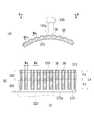
- FIG. 4 is a diagram illustrating the groove 38 on the outer periphery of the peripheral wall portion 372 of the rear cylinder 37.
- 4A is a cross-sectional view taken along the line AA in FIG. 2
- FIG. 4B is a developed view of the peripheral wall portion 372 viewed from the direction of the arrow AA in FIG. is there.
- the groove 38 is shown with hatching.
- the rotational driving force of the engine (not shown) is input to the forward / reverse switching mechanism 5 via a torque converter (not shown).
- the forward / reverse switching mechanism 5 has a planetary gear set 6, a forward clutch 51, and a reverse brake 52.
- the forward clutch 51 when the forward clutch 51 is engaged, the rotation input from the torque converter side is output to the variator 2 in forward rotation.
- the reverse brake 52 When the reverse brake 52 is engaged, the rotation input from the torque converter side is output to the variator 2 in reverse rotation.
- the variator 2 has a pair of pulleys (a primary pulley 3 and a secondary pulley 4) and a belt V (an endless annular member) wound around the pair of pulleys.
- a pair of pulleys a primary pulley 3 and a secondary pulley 4
- a belt V an endless annular member wound around the pair of pulleys.
- the primary pulley 3 has a fixed pulley 31 (fixed pulley) and a slide pulley 32 (movable pulley).
- the fixed pulley 31 has a shaft portion 311 arranged along the rotation axis X1, and a sheave portion 312 extending radially outward from the outer circumference of the shaft portion 311.
- Bearings 34A and 34B are externally fitted and fixed to one end 311a and the other end 311b of the shaft portion 311 in the longitudinal direction, respectively.
- One end 311a and the other end 311b of the shaft portion 311 are rotatably supported by the support hole 15 on the side cover 13 side and the support portion 101 on the transmission case 10 side via bearings 34A and 34B, respectively.
- the connecting member 641 included in the carrier 64 (see FIG. 2) of the planetary gear set 6 is connected to the other end 311b of the shaft portion 311 so as to be relatively unrotatable.
- the slide pulley 32 has an annular base portion 321 that is externally inserted into the shaft portion 311 of the fixed pulley 31, and a sheave portion 322 that extends radially outward from the outer circumference of the annular base portion 321.
- the annular base portion 321 of the slide pulley 32 is spline-fitted to the outer periphery of the shaft portion 311, and the slide pulley 32 is regulated in relative rotation with the fix pulley 31 so that the axial direction of the shaft portion 311 (rotating shaft) is reduced. It is provided so as to be movable in the X1 direction).
- the sheave portion 312 of the fixed pulley 31 and the sheave portion 322 of the slide pulley 32 are opposed to each other with a gap in the rotation axis X1 direction.
- a V groove 33 around which the belt V is wound is formed between the sheave surface 312a of the fixed pulley 31 and the sheave surface 322a of the slide pulley 32.
- a cylindrical cylinder portion 323 is provided on the pressure receiving surface 322b opposite to the sheave surface 322a.
- the cylinder portion 323 is provided in a direction along the rotation axis X1 and has a predetermined length L1 in a direction away from the sheave portion 322.
- the outer peripheral portion 35a of the front plunger 35 is in contact with the inner periphery of the cylinder portion 323.
- the D ring 9 is attached to the outer peripheral portion 35a of the front plunger 35, and the gap between the inner periphery of the cylinder portion 323 and the outer peripheral portion 35a is sealed by the D ring 9.
- the inner peripheral portion 35b of the front plunger 35 is in contact with the outer periphery of the annular base portion 321 of the slide pulley 32 from the outside in the radial direction.
- the D ring 9 is attached to the inner peripheral portion 35b of the front plunger 35, and the gap between the outer periphery of the annular base 321 and the inner peripheral portion 35b is sealed by the D ring 9.
- a space between the front plunger 35 and the sheave portion 322 is an oil chamber R1 to which operating oil pressure is supplied.
- a small diameter portion 324 is provided at the end opposite to the sheave portion 322.
- a ring-shaped rear plunger 36 is press-fitted into the small diameter portion 324.
- the inner peripheral portion 36b of the rear plunger 36 is fixed while being pressed into a stepped portion on the sheave portion 322 side (right side in the drawing) of the small diameter portion 324.
- the rear plunger 36 is provided immovably in the direction of the rotation axis X1 in a state in which the relative rotation with the annular base 321 is restricted.
- the outer peripheral portion 36a of the rear plunger 36 is in contact with the inner periphery of the cylindrical peripheral wall portion 372 of the rear cylinder 37 from the rotation axis X1 side.
- the D ring 9 is attached to the outer peripheral portion 36a of the rear plunger 36, and the gap between the inner periphery of the peripheral wall portion 372 and the outer peripheral portion 36a is sealed by the D ring 9.
- the rear cylinder 37 is composed of a disc portion 371 that is externally inserted on the shaft portion 311 and a peripheral wall portion 372 that surrounds the outer periphery of the disc portion 371 over the entire circumference.
- the shaft portion 311 is press-fitted into the inner peripheral portion 371b of the disc portion 371, and the inner peripheral portion 371b of the disc portion 371 is externally inserted into the step portion 314 provided on the shaft portion 311 and the shaft portion 311. It is sandwiched between the bearing 34A and the bearing.
- the bearing 34A is a nut N screwed onto the outer circumference of the shaft portion 311 and is positioned in the direction of the rotation axis X1, and the rear cylinder 37 adjacent to the bearing 34A moves in the direction away from the slide pulley 32. It is regulated by 34A.
- the peripheral wall portion 372 is formed with an outer diameter smaller than the inner diameter of the cylindrical cylinder portion 323 described above, and the tip portion 372a of the peripheral wall portion 372 is inside the cylinder portion 323, and is located from the direction of the rotation axis X1 in the front plunger 35 direction. Is in contact with.
- the front end portion 372a of the peripheral wall portion 372 restricts the movement of the front plunger 35 in the direction away from the sheave portion 322 (left direction in the drawing).
- the outer peripheral portion 35a and the inner peripheral portion 35b are offset in the rotation axis direction, and the outer peripheral portion 35a is located closer to the sheave portion 322 side of the slide pulley 32 than the inner peripheral portion 35b. There is.
- the tip portion 372a of the peripheral wall portion 372 is in contact with the region of the front plunger 35 on the outer peripheral portion 35a side from the direction of the rotation axis X1.
- the space surrounded by the rear plunger 36, the front plunger 35, and the peripheral wall portion 372 of the rear cylinder 37 serves as a second oil chamber R2 to which the working hydraulic pressure is supplied.
- the oil chamber R1 and the oil chamber R2 are adjacent to each other on the inner side (left side in the drawing) viewed from the sheave surface 322a with the front plunger 35 interposed therebetween.
- the oil chamber R1 and the oil chamber R2 form a pulley pressure receiving chamber on the primary pulley 3 side. Therefore, the pressure receiving area of each pulley pressure receiving chamber (oil chambers R1 and R2) can be reduced, and the outer diameter of the primary pulley 3 (sheave portions 322 and 312) can be reduced. There is.
- the shaft portion 311 of the fix pulley 31 is provided with an in-shaft oil passage 313 for supplying operating oil pressure to the oil chambers R1 and R2.
- the in-shaft oil passage 313 opens at one end 311a on the side cover 13 side (left side in the drawing).
- a support tube 152 provided on the side cover 13 is loosely fitted to the side cover 13 side (left side in the drawing) of the in-shaft oil passage 313.
- a cylindrical bush 153 is externally fitted to the support cylinder 152, and the side cover 13 side of the shaft portion 311 is rotatably supported by the bush 153 fitted in the axial oil passage 313. In this state, the seal ring S provided on the outer circumference of the bush 153 seals the gap between the outer circumference of the bush 153 and the inner circumference of the axial oil passage 313.
- a support hole 15 of the bearing 34A is opened at a portion facing the transmission case 10.
- a recess 151 for avoiding interference with the shaft portion 311 of the fixed pulley 31 is formed in the central portion of the support hole 15 when viewed from the direction of the rotation axis X1.
- the support cylinder 152 described above is provided at the center of the recess 151.
- Hydraulic pressure (oil OL) is supplied to the support cylinder 152 from an oil pressure control circuit (not shown) via an oil passage 131 in the side cover.
- the hydraulic pressure supplied to the support cylinder 152 is supplied to the oil chambers R1 and R2 (pulley pressure receiving chambers) attached to the slide pulley 32 through the in-shaft oil passage 313.
- the slide pulley 32 is displaced in the direction of the rotation axis X1 by adjusting the supply pressure to the oil chambers R1 and R2 (pulley pressure receiving chambers) attached to the slide pulley 32. Accordingly, the groove width of the V groove 33 between the sheave surfaces 312a and 322a is changed according to the supply pressure of the oil OL, and the winding radius of the belt V on the primary pulley 3 is changed.
- the secondary pulley 4 has a fixed pulley 41 (fixed pulley) and a slide pulley 42 (movable pulley).
- the fixed pulley 41 has a shaft portion 411 (pulley shaft) arranged along the rotation axis X2, and a sheave portion 412 that extends radially outward from the outer circumference of the shaft portion 411.
- the slide pulley 42 has an annular base portion 421 that is externally inserted into the shaft portion 411 of the fixed pulley 41, and a sheave portion 422 that extends radially outward from the outer circumference of the annular base portion 421.
- the sheave portion 412 of the fixed pulley 41 and the sheave portion 422 of the slide pulley 42 are opposed to each other with a gap in the rotation axis X2 direction.
- a V groove 43 around which the belt V is wound is formed between the sheave surface 412a of the fixed pulley 41 and the sheave surface 422a of the slide pulley 42.
- Bearings 44A and 44B are externally fitted to the shaft portion 411 of the fixed pulley 41 at one end portion 411a and the other end portion 411b in the rotation axis X2 direction.
- the other end 411b of the shaft 411 in the rotation axis X2 direction is rotatably supported by the support 102 on the transmission case 10 side via the bearing 44B.
- One end 411a of the shaft 411 in the direction of the rotation axis X2 is rotatably supported by the support hole 16 on the side cover 13 side via the bearing 44A.
- the support hole 16 of the bearing 44A is opened at the portion facing the transmission case 10.
- a recess 161 for avoiding interference with the shaft portion 411 of the fixed pulley 41 is formed in the central portion of the support hole 16 when viewed from the direction of the rotation axis X2.
- a support cylinder 162 is provided at the center of the recess 161.
- the support cylinder 162 projects to the transmission case 10 side (right side in the drawing), and the tip end side of the support cylinder 162 is loosely fitted in the in-shaft oil passage 413 of the fix pulley 41.
- a cylindrical bush 163 is fitted onto the support cylinder 162, and the side cover 13 side of the shaft portion 411 is rotatably supported by the bush 163 fitted inside the shaft oil passage 413. In this state, the seal ring S provided on the outer circumference of the bush 163 seals the gap between the outer circumference of the bush 163 and the inner circumference of the axial oil passage 413.
- the in-shaft oil passage 413 opens at one end 411a of the shaft 411.
- the in-shaft oil passage 413 extends linearly in the shaft portion 411 along the rotation axis X2 of the fixed pulley 41, and the inner diameter side of the slide pulley 42 externally inserted in the shaft portion 411 is moved in the rotation axis X2 direction. Crossing.
- An oil hole 414 that communicates the in-shaft oil passage 413 and the outer periphery of the shaft portion 411 is provided on the tip side (right side in the drawing) of the in-shaft oil passage 413.
- Hydraulic pressure is supplied to the support cylinder 162 from an oil pressure control circuit (not shown) via an oil passage 132 in the side cover.
- the hydraulic pressure supplied to the support cylinder 162 passes through the in-shaft oil passage 413 and is supplied to the oil chamber R3 located on the outer diameter side of the shaft portion 411.
- the slide pulley 42 is displaced in the direction of the rotation axis X2 by adjusting the supply pressure to the oil chamber R3 (pulley pressure receiving chamber) attached to the slide pulley 42.
- the groove width of the V groove 43 between the sheave surfaces 412a and 422a is changed according to the supply pressure, and the winding radius of the belt V on the secondary pulley 4 is changed.
- a cylinder portion 423 is provided on a pressure receiving surface 422b opposite to the sheave surface 422a.
- the cylinder portion 423 is provided in a direction along the rotation axis X2, and has a predetermined length L2 in a direction away from the sheave portion 422.
- the outer peripheral portion 45a of the plunger 45 is in contact with the inner peripheral surface of the cylinder portion 423.
- the D ring 9 is attached to the outer peripheral portion 45a of the plunger 45, and the gap between the inner periphery of the cylinder portion 423 and the outer peripheral portion 45a is sealed by the D ring 9.
- a cylindrical fitting portion 451 is provided on the inner diameter side of the plunger 45.
- the fitting portion 451 is spline-fitted to the outer circumference of the shaft portion 411 of the fixed pulley 41.
- the fitting portion 451 of the plunger 45 is positioned in the rotation axis X2 direction between the bearing 44B and the step portion 411c of the shaft portion 411.
- the region of the plunger 45 adjacent to the fitting portion 451 extends on the outer diameter side of the annular base portion 421 of the slide pulley 42 in a direction approaching the sheave portion 422 (leftward in the drawing) and then bends to the outer diameter side. is doing.
- one end of the spring Sp is in contact with the region 452 that is bent toward the outer diameter side from the rotation axis X2 direction.
- the other end of the spring Sp is in contact with the pressure receiving surface 422b of the sheave portion 422.
- the spring Sp is provided in a state of being compressed in the direction of the rotation axis X2, and the slide pulley 42 is a direction in which the width of the V groove 43 is narrowed by the urging force acting from the spring Sp (the speed ratio of the variator 2 is set to the highest level). It is pressed in the direction (to the side).
- a boss portion 17 having a bolt hole 17a is provided at a position adjacent to the support hole 15 of the bearing 34A.
- a plurality of the boss portions 17 are provided at predetermined intervals in the circumferential direction around the rotation axis X1.
- the bolt hole 17a is formed along the axis Xa and penetrates the side cover 13 in the thickness direction.
- the axis Xa is an axis parallel to the rotation axis X1 of the primary pulley 3.
- a ring-shaped retainer 18 surrounding the support hole 15 of the bearing 34A is provided inside the side cover 13.
- the retainer 18 has an inner diameter smaller than the opening diameter of the support hole 15 in order to prevent the bearing 34A from falling off the support hole 15.
- the shaft portion B1 of the bolt B causes the retainer 18 to move in the axial direction Xa in the side cover 13. To penetrate.
- the retainer 18 is arranged at a position that supports the outer race of the bearing 34A.
- the peripheral wall portion 372 of the rear cylinder 37 is located on the extension of the axis line Xa passing through the center of the bolt hole 17 a of the boss portion 17. That is, the bolt B is arranged at a position overlapping the peripheral wall portion 372 located at the outermost peripheral portion of the rear cylinder 37 when viewed from the direction of the axis Xa (rotational axis X1).
- the tip Bx of the bolt B faces the boundary portion 373 between the disk portion 371 and the peripheral wall portion 372 of the rear cylinder 37 in the direction of the axis Xa, and is provided with a gap CL1 between the boundary portion 373 and the boundary portion 373. Has been.
- the clearance CL1 is larger than that of the rear cylinder 37 when the pulley cylinder pressure receiving chamber (oil chamber R1, oil chamber R2) is supplied with a hydraulic pressure of a predetermined value or more and the rear cylinder 37 is deformed.
- the boundary portion 373 is set to have a width that contacts the tip Bx of the bolt B.
- a hydraulic pressure equal to or higher than a predetermined value is supplied to the pulley pressure receiving chambers (oil chamber R1, oil chamber R2) is, for example, when a malfunction of a valve in a control valve (not shown) occurs.
- the contact timing is set such that the deformation of the rear cylinder 37 is before the deformation of the rear cylinder 37 reaches the region of plastic deformation (before yielding). This is because when the plastic deformation region is reached, the shape of the rear cylinder 37 may not return to its original shape even if the hydraulic pressure in the pulley pressure receiving chambers (oil chamber R1, oil chamber R2) returns to normal pressure.
- the clearance CL1 is set in order to allow the elastic deformation of the rear cylinder 37 and suppress the plastic deformation. That is, when the rear cylinder 37 starts to be deformed, the bolt B, which is a stopper member, comes into contact with the rear cylinder 37, so that plastic deformation of the rear cylinder 37 is prevented. At least, the plastic deformation of the rear cylinder 37 is minimized.
- the thickness of the rear cylinder 37 (disk portion 371, peripheral wall portion 372) can be reduced, and the primary pulley 3 can be made lighter.
- the outer periphery of the boundary portion 373 between the disk portion 371 and the peripheral wall portion 372 of the rear cylinder 37 is rounded. This is because when the bolt B is brought into contact with the tip Bx, the periphery of the boundary portion 373 is less likely to be damaged.
- a groove 38 that extends linearly along the rotation axis X1 is provided in the peripheral wall portion 372 facing the tip Bx of the bolt B. As shown in FIGS. 4A and 4B, when viewed in the radial direction of the rotation axis X1, the groove 38 extends from the region overlapping the disk portion 371 to the vicinity of the tip portion 372a of the peripheral wall portion 372. It is formed with a length Lx in the X1 direction. The groove 38 is formed with the same width Wx over the entire length in the rotation axis X1 direction.
- the grooves 38 are provided at a predetermined interval (predetermined width Wx) in the circumferential direction around the rotation axis X1.
- the groove 38 is provided over the entire circumference in the circumferential direction around the rotation axis X1.
- an area where the groove 38 is formed and an area where the groove 38 is not formed are formed with the same width Wx in the circumferential direction, and an area where the groove 38 is formed and an area where the groove 38 is not formed. And are located alternately.
- a tip portion 372a of the peripheral wall portion 372 is a contact portion that contacts the front plunger 35 from the direction of the rotation axis X1.
- a pressing force corresponding to the hydraulic pressure supplied to the oil chamber R1 acts on the tip portion 372a from the front plunger 35 side.
- the groove 38 is formed within the range of the length Lx in the direction of the rotation axis X1 extending to the vicinity of the tip portion 372a of the peripheral wall portion 372. .
- the groove 38 is provided for the purpose of using the rotation speed sensor 120 as a detected portion and thinning the rear cylinder 37 for weight reduction.
- a rotation speed sensor 120 is provided at a position closer to the disk portion 371 on the outer diameter side of the peripheral wall portion 372, and the rotation speed sensor 120 is provided with the detection surface 120 a facing the peripheral wall portion 372.
- the detection surface 120a which is the detection portion of the rotation speed sensor 120, is arranged in the radial direction.
- a region facing the detection surface 120a is a first groove 381 that is a region that functions as a detected portion of the rotation speed sensor 120, and a second groove 382 that is a region excluding the first groove 381.
- it is a meat removal part.
- the first groove portion 381 and the second groove portion 382 are connected in series, and the first groove portion 381 is located closer to the disc portion 371.
- the length La of the first groove portion 381 in the rotation axis X1 direction is shorter than the length Lb of the second groove portion 382 (La ⁇ Lb).
- the groove width of the V groove 33 (width in the rotation axis X1 direction) is changed by displacing the slide pulley 32 in the rotation axis X1 direction in conjunction with the change of the gear ratio in the variator 2.
- the groove width of the V groove 33 is maximum when the gear ratio is lowest (see FIG. 3A), and is minimum when the gear ratio is highest (see FIG. 3B).
- the cylinder portion 323 of the slide pulley 32 is also displaced in the rotation axis X1 direction.
- the length La of the first groove portion 381 is set so that the cylinder portion 323 displaced in the direction of the rotation axis X1 does not interfere with the rotation speed sensor 120.
- the first groove portion 381 does not overlap with the cylinder portion 323 (pulley cylinder portion) in the radial direction of the rotation axis X1. That is, in the present embodiment, the moving range of the cylinder portion 323, which is interlocked with the movement of the slide pulley 32 in the rotation axis X1 direction, does not overlap the first groove portion 381 when viewed in the radial direction.
- the second groove portion 382 overlaps the cylinder portion 323 in the radial direction when the groove width of the V groove 33 becomes equal to or larger than the predetermined width.
- the first groove portion 381 which is the detected portion of the rotation speed sensor 120, does not overlap the cylinder portion 323 in the radial direction in the region of the entire gear ratio of the variator 2, so that the rotation speed sensor 120 It avoids the interference with the cylinder part 323.
- the second groove portion 382 is a region that does not function as the detected portion of the rotation speed sensor 120, the second groove portion 382 radially overlaps with the cylinder portion 323 in the region of the predetermined gear ratio of the variator 2. Since the second groove portion 382 extends in the range extending to the inner peripheral side of the cylinder portion 323, the weight reduction due to the thinning of the peripheral wall portion 372 contributes greatly.
- the second groove portion 382 has a length that overlaps with the cylinder portion 323 in the region of the entire gear ratio, from the viewpoint of weight reduction, but the second groove portion 382 overlaps in the region of some gear ratio and the other part. It may be designed so that there is no overlap in the area of the gear ratio.
- the continuously variable transmission 1 has the following configuration.
- the continuously variable transmission 1 A fixed pulley 31 and A slide pulley 32, A belt V (endless annular member) sandwiched between the fixed pulley 31 and the slide pulley 32;
- a rear cylinder 37 (cylinder member) fixed to the fixed pulley 31 and having peripheral wall portions 372 (cylinder cylinder portions) of the oil chambers R1 and R2 (pulley pressure receiving chambers);
- a bolt B stopper member provided at a position in contact with the rear cylinder 37 when a hydraulic pressure of a predetermined value or more is supplied to the oil chambers R1 and R2 (pulley pressure receiving chambers).
- the position of the bolt B and the thickness of the rear cylinder 37 are set so that the plastic deformation is suppressed while allowing the elastic deformation of the rear cylinder 37, and when the deformation of the rear cylinder 37 starts, The rear cylinder 37 is brought into contact with the bolt B before plastic deformation occurs. Then, the rear cylinder 37 can be prevented from being plastically deformed, or the plastic deformation can be kept to a minimum. As a result, when the supply of the hydraulic pressure equal to or higher than the predetermined value is canceled, the rear cylinder 37 quickly returns to its original shape, so that the trouble due to the deformation of the rear cylinder 37 may occur in the oil chambers R1 and R2. It can be preferably prevented.
- the thickness of the rear cylinder 37 can be reduced, and the weight of the rear cylinder 37 can be reduced by the reduced thickness.
- a safety valve valve
- the continuously variable transmission 1 has the following configuration.
- the bolt B which is a stopper member, is arranged at a position overlapping the peripheral wall portion 372 located at the outermost peripheral portion of the rear cylinder 37 when viewed from the direction of the rotation axis X1.
- the rear cylinder 37 After the rear cylinder 37 contacts the bolt B, it is not preferable that the rear cylinder 37 is further deformed by the lever principle with the contact point with the bolt B as a fulcrum.
- the contact point with the bolt B By providing the bolt B in the vicinity of the peripheral wall portion 372 located on the outermost peripheral portion of the rear cylinder 37, when the rear cylinder 37 is deformed, the contact point with the bolt B is used as a fulcrum to further deform by the lever principle. It can be preferably prevented.
- the rear cylinder 37 includes a cylindrical peripheral wall portion 372 arranged along the extension line of the bolt B, and a disk portion 371 that seals the opening of the peripheral wall portion 372 on the bolt B side. Is formed in. Then, the tip Bx of the bolt B is arranged at a position facing the boundary portion 373 between the disc portion 371 and the peripheral wall portion 372, with a gap CL1 provided between the bolt portion B and the boundary portion 373.
- the boundary portion 373 between the disc portion 371 and the peripheral wall portion 372 has higher rigidity and strength than other portions, so that when the rear cylinder 37 is deformed, the boundary portion 373 contacts the bolt B. By making contact with each other, the deformation of the rear cylinder 37 can be prevented more preferably.
- the position where the bolt B contacts the rear cylinder 37 may be a region other than the boundary 373 because the rear cylinder 37 is not plastically deformed or the plastic deformation can be minimized. .
- the stopper member is the bolt B
- any other member may be used as long as it can contact the rear cylinder 37 and prevent plastic deformation of the rear cylinder 37.
- a bulging portion may be provided on the inner circumference of the side cover 13, and the rear cylinder may be brought into contact with the bulging portion to suppress plastic deformation.
- the continuously variable transmission 1 has the following configuration. (3) When the hydraulic pressure supplied to the oil chambers R1 and R2 (pulley pressure receiving chamber) is less than the predetermined value, the rear cylinder 37 does not contact the bolt B that is the stopper member.
- the bolt B is a fixed element fixed to the side cover 13 (case), and the rear cylinder 37 is a rotating element that rotates together with the primary pulley 3 (pulley). Therefore, if the rear cylinder 37 and the bolt B, which is the stopper member, are always brought into contact with each other, they interfere with each other and cause noise. Therefore, when the hydraulic pressure supplied to the oil chambers R1 and R2 (pulley pressure receiving chambers) is less than a predetermined value in a normal state, the rear cylinder 37 and the bolt B are prevented from abutting against each other, so that noise is preferably generated. It can be prevented.
- the continuously variable transmission 1 has the following configuration. (4) When hydraulic pressure of a predetermined value or more is supplied to the oil chambers R1 and R2 (pulley pressure receiving chambers), the rear cylinder 37 comes into contact with the bolt B that is a stopper member before being plastically deformed.
- the rear cylinder 37 is not plastically deformed, or the plastic deformation can be minimized, but it is preferable that the rear cylinder is not plastically deformed.
- the above-mentioned definition states that "when the hydraulic pressure of the predetermined value or more is supplied to the pulley pressure receiving chamber, the cylinder member and the stopper member are brought into contact with the stopper member before the cylinder member is plastically deformed. The distance has been set. "
- a groove 38 extending in the rotation axis X1 direction is formed on the outer periphery of the peripheral wall portion 372 of the rear cylinder 37, and a plurality of grooves 38 are provided at predetermined intervals in the circumferential direction around the rotation axis X1. . Therefore, by providing the plurality of grooves 38, the region between the adjacent grooves 38 functions as a reinforcing rib. Therefore, when the rear cylinder 37 comes into contact with the bolt B, it is possible to suppress the occurrence of large deformation in the peripheral wall portion 372.
Landscapes
- Engineering & Computer Science (AREA)
- General Engineering & Computer Science (AREA)
- Mechanical Engineering (AREA)
- Transmissions By Endless Flexible Members (AREA)
Abstract
Description
(A)そもそも高油圧がプーリ室に供給されないようにする。
例えば、所定油圧以上になるとオイルをリリースするバルブを設けて、プーリ油圧室に所定以上の油圧が供給されないようにする。
(B)所定油圧以上が供給されていてもシリンダ部材が変形しないようにする。
例えば、シリンダ部材は剛性を高めるべくシリンダ部材の板厚を厚くする。
フィックスプーリと、
スライドプーリと、
前記フィックスプーリと、前記スライドプーリと、に挟まれた無端環状部材と、
前記フィックスプーリに固定され、プーリ受圧室の壁を構成するシリンダ筒部を有するシリンダ部材と、
前記プーリ受圧室に所定値以上の油圧が供給されたときに前記シリンダ部材と当接する位置に設けられたストッパ部材と、を有する構成の無段変速機とした。
図1は、無段変速機1の要部構成を説明する図である。
図2は、無段変速機のプライマリプーリ3と前後進切替機構5周りを説明する図である。
図3は、プライマリプーリ3の要部を説明する図である。図3の(a)は、バリエータ2の変速比が最Lowの場合のスライドプーリ32とリアシリンダ37との位置関係を説明する図である。図3の(b)は、バリエータ2の変速比が最Highの場合のスライドプーリ32とリアシリンダ37との位置関係を説明する図である。
図4は、リアシリンダ37の周壁部372の外周の溝38を説明する図である。図4の(a)は、図2におけるA-A断面図であり、図4の(b)は、図4の(a)におけるA-A矢視方向から周壁部372を見た展開図である。図4の(b)では、説明の便宜上、溝38の部分にハッチングを付して示している。
前後進切替機構5は、遊星歯車組6と、前進クラッチ51と、後進ブレーキ52と、を有している。
前後進切替機構5では、前進クラッチ51が締結されると、トルクコンバータ側から入力された回転が、順回転でバリエータ2に出力される。後進ブレーキ52が締結されると、トルクコンバータ側から入力された回転が、逆回転でバリエータ2に出力される。
バリエータ2では、一対のプーリ(プライマリプーリ3、セカンダリプーリ4)におけるベルトVの巻き掛け半径を変更することで、前後進切替機構5側から入力された回転が、所望の変速機で変速されて、終減速機構(図示せず)側に出力される。
フィックスプーリ31は、回転軸X1に沿って配置された軸部311と、軸部311の外周から径方向外側に延びるシーブ部312とを、有している。
軸部311の一端311aと他端311bは、それぞれベアリング34A、34Bを介して、サイドカバー13側の支持孔15と変速機ケース10側の支持部101で回転可能に支持されている。
スライドプーリ32の環状基部321は、軸部311の外周にスプライン嵌合しており、スライドプーリ32は、フィックスプーリ31との相対回転が規制された状態で、軸部311の軸方向(回転軸X1方向)に移動可能に設けられている。
プライマリプーリ3では、フィックスプーリ31のシーブ面312aと、スライドプーリ32のシーブ面322aの間に、ベルトVが巻き掛けられるV溝33が形成されている。
シリンダ部323は、回転軸X1に沿う向きで設けられており、シーブ部322から離れる方向に所定長さL1で形成されている。
フロントプランジャ35の外周部35aには、Dリング9が取り付けられており、シリンダ部323の内周と外周部35aとの隙間がDリング9で封止されている。
フロントプランジャ35の内周部35bには、Dリング9が取り付けられており、環状基部321の外周と内周部35bとの隙間がDリング9で封止されている。
プライマリプーリ3では、フロントプランジャ35と、シーブ部322との間が、作動油圧が供給される油室R1となっている。
小径部324には、リング状のリアプランジャ36が圧入されている。リアプランジャ36の内周部36bは、小径部324のシーブ部322側(図中、右側)の段差部まで圧入された状態で固定されている。
この状態においてリアプランジャ36は、環状基部321との相対回転が規制された状態で、回転軸X1方向に移動不能に設けられている。
リアプランジャ36の外周部36aには、Dリング9が取り付けられており、周壁部372の内周と、外周部36aとの隙間がDリング9で封止されている。
円板部371の内周部371bには、軸部311が圧入されており、円板部371の内周部371bは、軸部311に設けた段部314と、軸部311に外挿されたベアリング34Aとの間に挟まれている。
周壁部372の先端部372aは、フロントプランジャ35のシーブ部322から離れる方向(図中、左方向)への移動を規制している。
周壁部372の先端部372aは、フロントプランジャ35における外周部35a側の領域に、回転軸X1方向から当接している。
プライマリプーリ3では、リアプランジャ36とフロントプランジャ35とリアシリンダ37の周壁部372で囲まれた空間が、作動油圧が供給されるふたつめの油室R2となっている。
そのため、1つずつのプーリ受圧室(油室R1、R2各々)の受圧面積を小さくすることができるので、プライマリプーリ3(シーブ部322、312)の外径の縮小が可能な構成となっている。
軸部311において軸内油路313は、サイドカバー13側(図中、左側)の一端311aに開口している。軸内油路313のサイドカバー13側(図中、左側)には、サイドカバー13に設けた支持筒152が遊嵌している。支持筒152には、円筒状のブッシュ153が外嵌しており、軸部311のサイドカバー13側は、軸内油路313に内嵌したブッシュ153で回転可能に支持されている。
この状態で、ブッシュ153の外周に設けたシールリングSは、ブッシュ153の外周と、軸内油路313の内周との間の隙間を封止している。
フィックスプーリ41は、回転軸X2に沿って配置された軸部411(プーリ軸)と、軸部411の外周から径方向外側に延びるシーブ部412とを、有している。
スライドプーリ42は、フィックスプーリ41の軸部411に外挿された環状基部421と、環状基部421の外周から径方向外側に延びるシーブ部422と、を有している。
セカンダリプーリ4では、フィックスプーリ41のシーブ面412aと、スライドプーリ42のシーブ面422aとの間に、ベルトVが巻き掛けられるV溝43が形成されている。
回転軸X2方向における軸部411の他方の端部411bは、ベアリング44Bを介して、変速機ケース10側の支持部102で回転可能に支持されている。
回転軸X2方向における軸部411の一方の端部411aは、ベアリング44Aを介して、サイドカバー13側の支持孔16で回転可能に支持されている。
支持筒162には、円筒状のブッシュ163が外嵌しており、軸部411のサイドカバー13側は、軸内油路413に内嵌したブッシュ163で回転可能に支持されている。
この状態で、ブッシュ163の外周に設けたシールリングSは、ブッシュ163の外周と、軸内油路413の内周との間の隙間を封止している。
前記した支持筒162には、サイドカバー内の油路132を介して図示しない油圧制御回路から油圧が供給される。支持筒162に供給された油圧は、軸内油路413を通って、軸部411の外径側に位置する油室R3に供給される。
シリンダ部423は、回転軸X2に沿う向きで設けられており、シーブ部422から離れる方向に所定長さL2で形成されている。
プランジャ45の外周部45aには、Dリング9が取り付けられており、シリンダ部423の内周と外周部45aとの隙間がDリング9で封止されている。
プランジャ45では、この外径側に屈曲した領域452に、スプリングSpの一端が、回転軸X2方向から当接している。スプリングSpの他端は、シーブ部422の受圧面422bに当接している。スプリングSpは回転軸X2方向に圧縮された状態で設けられており、スライドプーリ42は、スプリングSpから作用する付勢力で、V溝43の溝幅を狭める方向(バリエータ2の変速比を最High側にする方向)に押圧されている。
このボス部17は、回転軸X1周りの周方向に所定間隔で複数設けられている。
すなわち、ボルトBは、軸線Xa(回転軸X1)方向から視たときにリアシリンダ37の最外周部に位置する周壁部372とオーバーラップする位置に配置されている。
プーリ受圧室(油室R1、油室R2)内に所定値以上の油圧が供給される場合とは、一例として、図示しないコントロールバルブ内のバルブの不具合等が発生した場合である。
即ち、リアシリンダ37の変形が始まったときに、ストッパ部材であるボルトBがリアシリンダ37とが当接するので、リアシリンダ37の塑性変形を阻止する。少なくとも、リアシリンダ37の塑性変形を必要最小限にとどめるようにしている。
図4の(a)、(b)に示すように、回転軸X1の径方向から見て溝38は、円板部371と重なる領域から、周壁部372の先端部372aの近傍まで及ぶ回転軸X1方向の長さLxで形成されている。
溝38は、回転軸X1方向の全長に亘って等しい幅Wxで形成されている。
周壁部372の外周では、溝38が形成された領域と、形成されていない領域が、周方向に同じ幅Wxで形成されていると共に、溝38が形成された領域と、形成されていない領域とが交互に位置している。
本実施形態では、先端部372a側の剛性と強度を確保するために、溝38は、周壁部372の先端部372aの近傍まで及ぶ回転軸X1方向の長さLxの範囲内で形成されている。
周壁部372の外径側の円板部371寄りの位置には、回転速度センサ120が設けられており、回転速度センサ120は、検知面120aを周壁部372に向けて設けられている。この状態において回転速度センサ120の検出部である検知面120aは、径方向に向かって配置されている。
溝38では、検知面120aが対向する領域が、回転速度センサ120の被検出部として機能する領域である第1溝部381となっており、第1溝部381を除いた領域である第2溝部382が、肉抜き部となっている。
そして、回転軸X1方向における第1溝部381の長さLaは、第2溝部382の長さLbよりも短くなっている(La<Lb)。
ここで、V溝33の溝幅は、変速比が最Lowの時に最大となり(図3の(a)参照)、最Highの時に最小となる(図3の(b)参照)。
本実施形態では、回転軸X1方向に変位するシリンダ部323が、回転速度センサ120に干渉しないようにするために、第1溝部381の長さLaを設定している。
一方、第2溝部382は、V溝33の溝幅が所定幅以上になると、径方向においてシリンダ部323とオーバーラップする。
(1)無段変速機1は、
フィックスプーリ31と、
スライドプーリ32と、
フィックスプーリ31と、スライドプーリ32と、に挟まれたベルトV(無端環状部材)と、
フィックスプーリ31に固定され、油室R1、R2(プーリ受圧室)の周壁部372(シリンダ筒部)を有するリアシリンダ37(シリンダ部材)と、
油室R1、R2(プーリ受圧室)に所定値以上の油圧が供給されたときに、リアシリンダ37と当接する位置に設けられたボルトB(ストッパ部材)と、を有する。
そうすると、リアシリンダ37を塑性変形させない、若しくは、塑性変形を必要最小限に留めることができる。
これにより、所定値以上の油圧の供給が解消されると、リアシリンダ37は、速やかに元の形状に復帰するので、油室R1、R2にリアシリンダ37の変形に起因する支障が生ずることを好適に防止できる。
よって、リアシリンダ37の構成部位の厚みを薄くすることが可能となり、厚みが薄くなった分だけ、リアシリンダ37の軽量化が可能となる。
また、油室R1、R2(プーリ受圧室)に所定値以上の油圧が供給されないようにするための安全弁(バルブ)を別途用意する必要がないので、部品点数の増加を防ぐことができる。
(2)ストッパ部材であるボルトBは、回転軸X1方向から視たときにリアシリンダ37の最外周部に位置する周壁部372とオーバーラップする位置に配置されている。
リアシリンダ37の最外周部に位置する周壁部372付近にボルトBを設けることで、リアシリンダ37が変形した際に、ボルトBとの当接点を支点として、てこの原理で更に変形することを好適に防止できる。
このように構成すると、円板部371と周壁部372との境界部373は、他の部位よりも剛性と強度が高いので、リアシリンダ37が変形した際に、境界部373がボルトBに当接するようにすることで、リアシリンダ37の変形をより好適に防止できる。
(3)油室R1、R2(プーリ受圧室)に供給される油圧が所定値未満であるときには、リアシリンダ37は、ストッパ部材であるボルトBと当接しない。
そのため、リアシリンダ37と、ストッパ部材であるボルトBとを常に当接させると、干渉して騒音の原因となる。よって、油室R1、R2(プーリ受圧室)に供給される油圧が所定値未満である通常時には、リアシリンダ37とボルトBとが当接しないようにしておくことで、騒音の発生を好適に防止できる。
(4)油室R1、R2(プーリ受圧室)に所定値以上の油圧が供給されたときに、リアシリンダ37が塑性変形する前に、ストッパ部材であるボルトBと当接する。
上記規定は言い換えると、「前記プーリ受圧室に前記所定値以上の油圧が供給されたときに前記シリンダ部材が塑性変形する前に前記ストッパ部材と当接するように、前記シリンダ部材と前記ストッパ部材との距離が設定されている」という表現で表すことが可能である。
そのため、複数の溝38を設けたことで、隣接する溝38、38の間の領域が補強リブとして機能する。よって、リアシリンダ37がボルトBに当接した際に、周壁部372の部分での大きな変形の発生を抑制できるようになっている。
Claims (4)
- フィックスプーリと、
スライドプーリと、
前記フィックスプーリと、前記スライドプーリと、に挟まれた無端環状部材と、
前記フィックスプーリに固定され、プーリ受圧室の壁を構成するシリンダ筒部を有するシリンダ部材と、
前記プーリ受圧室に所定値以上の油圧が供給されたときに前記シリンダ部材と当接する位置に設けられたストッパ部材と、
を有する、無段変速機。 - 請求項1において、
前記ストッパ部材は、軸方向から視たときに前記シリンダ部材の最外周部とオーバーラップする位置に配置されている、無段変速機。 - 請求項2において、
前記プーリ受圧室に供給される油圧が前記所定値未満であるときには、前記シリンダ部材は前記ストッパ部材と当接しない、無段変速機。 - 請求項1乃至請求項3のいずれか一において、
前記プーリ受圧室に前記所定値以上の油圧が供給されたときに前記シリンダ部材が塑性変形する前に前記ストッパ部材と当接する、無段変速機。
Priority Applications (4)
| Application Number | Priority Date | Filing Date | Title |
|---|---|---|---|
| CN201980055835.8A CN112639329B (zh) | 2018-10-22 | 2019-09-09 | 无级变速器 |
| JP2020552950A JP7001837B2 (ja) | 2018-10-22 | 2019-09-09 | 無段変速機 |
| CN202411943324.9A CN119664862A (zh) | 2018-10-22 | 2019-09-09 | 无级变速器 |
| US17/270,256 US11835134B2 (en) | 2018-10-22 | 2019-09-09 | Continuously variable transmission |
Applications Claiming Priority (2)
| Application Number | Priority Date | Filing Date | Title |
|---|---|---|---|
| JP2018198804 | 2018-10-22 | ||
| JP2018-198804 | 2018-10-22 |
Publications (1)
| Publication Number | Publication Date |
|---|---|
| WO2020084936A1 true WO2020084936A1 (ja) | 2020-04-30 |
Family
ID=70331008
Family Applications (1)
| Application Number | Title | Priority Date | Filing Date |
|---|---|---|---|
| PCT/JP2019/035330 Ceased WO2020084936A1 (ja) | 2018-10-22 | 2019-09-09 | 無段変速機 |
Country Status (4)
| Country | Link |
|---|---|
| US (1) | US11835134B2 (ja) |
| JP (1) | JP7001837B2 (ja) |
| CN (2) | CN119664862A (ja) |
| WO (1) | WO2020084936A1 (ja) |
Families Citing this family (7)
| Publication number | Priority date | Publication date | Assignee | Title |
|---|---|---|---|---|
| WO2020172428A1 (en) | 2019-02-20 | 2020-08-27 | Team Industries, Inc. | Drivetrain layout with cvt |
| US11499608B2 (en) * | 2019-06-21 | 2022-11-15 | Team Industries, Inc. | Integrated launch clutch and drive sheave for steel belt continuously variable transmission |
| US11543006B2 (en) * | 2019-06-21 | 2023-01-03 | Team Industries, Inc. | Variable torque limiting clutch for a steel belt continuously variable transmission |
| US12018742B2 (en) * | 2021-02-22 | 2024-06-25 | Jatco Ltd | Sensor arrangement structure |
| CN113249855B (zh) * | 2021-06-22 | 2022-02-22 | 南通欧惠纺织科技有限公司 | 一种棉布生产中的喷气织机打纬力矩自动调节装置 |
| US12110951B2 (en) * | 2021-07-12 | 2024-10-08 | Team Industries, Inc. | Double clutch reverse and active torque management system |
| US12467533B2 (en) | 2023-10-18 | 2025-11-11 | Team Industries, Inc. | High-low shifting active torque management continuously variable transmission system |
Citations (2)
| Publication number | Priority date | Publication date | Assignee | Title |
|---|---|---|---|---|
| JP2005299698A (ja) * | 2004-04-06 | 2005-10-27 | Toyota Motor Corp | ベルト式無段変速機 |
| WO2011151916A1 (ja) * | 2010-06-03 | 2011-12-08 | トヨタ自動車株式会社 | 車両用ベルト式無段変速機 |
Family Cites Families (60)
| Publication number | Priority date | Publication date | Assignee | Title |
|---|---|---|---|---|
| US2A (en) * | 1826-12-15 | 1836-07-29 | John Goulding | Mode of manufacturing wool or other fibrous materials |
| JP3223241B2 (ja) * | 1997-03-17 | 2001-10-29 | 本田技研工業株式会社 | ベルト式無段変速機 |
| DE2846580C2 (de) * | 1978-10-26 | 1982-12-09 | P.I.V. Antrieb Werner Reimers GmbH & Co KG, 6380 Bad Homburg | Stufenlos einstellbares Kegelscheibengetriebe |
| US4717368A (en) * | 1986-01-23 | 1988-01-05 | Aisin-Warner Kabushiki Kaisha | Stepless belt transmission |
| JPH0612272Y2 (ja) * | 1986-05-31 | 1994-03-30 | スズキ株式会社 | 無段変速装置 |
| US5310384A (en) * | 1993-03-29 | 1994-05-10 | Borg-Warner Automotive, Inc. | Continuously variable transmission belt ratio measurement system |
| DE4411628A1 (de) * | 1994-04-02 | 1995-10-05 | Bosch Gmbh Robert | Schlupfregler für stufenloses Getriebe |
| JP3277087B2 (ja) * | 1995-01-10 | 2002-04-22 | 愛知機械工業株式会社 | 可動フランジを備えた無段変速機 |
| JP3138801B2 (ja) * | 1996-06-07 | 2001-02-26 | 本田技研工業株式会社 | 無段変速機用可動側プーリの製造方法 |
| JP3248615B2 (ja) * | 1997-01-24 | 2002-01-21 | 愛知機械工業株式会社 | ベルト式無段変速機のプーリ用シリンダ構造 |
| DE19857709B4 (de) * | 1997-12-22 | 2006-03-23 | Luk Gs Verwaltungs Kg | Getriebe |
| JP4048453B2 (ja) * | 1998-03-30 | 2008-02-20 | 富士重工業株式会社 | ベルト式無段変速機のプーリ構造 |
| DE19921749A1 (de) * | 1998-05-18 | 1999-11-25 | Luk Getriebe Systeme Gmbh | Getriebe |
| DE19921750B4 (de) * | 1998-05-18 | 2012-03-08 | Schaeffler Technologies Gmbh & Co. Kg | Getriebe |
| DE19952476A1 (de) * | 1999-10-29 | 2001-05-23 | Zahnradfabrik Friedrichshafen | Verfahren zur Steuerung eines CVT-Automatgetriebes |
| WO2001047739A1 (en) * | 1999-12-27 | 2001-07-05 | Speed Selector, Inc. | Variable speed drive system |
| JP2001263463A (ja) | 2000-03-22 | 2001-09-26 | Jatco Transtechnology Ltd | 変速機ユニット |
| JP3855599B2 (ja) * | 2000-05-23 | 2006-12-13 | トヨタ自動車株式会社 | 車両用無段変速機の制御装置 |
| JP2002295613A (ja) * | 2001-03-30 | 2002-10-09 | Honda Motor Co Ltd | ベルト式無段変速機 |
| DE50306264D1 (de) * | 2002-06-17 | 2007-02-22 | Luk Lamellen & Kupplungsbau | Kegelscheibenumschlingungsgetriebe |
| JP3981317B2 (ja) * | 2002-10-04 | 2007-09-26 | ジヤトコ株式会社 | 車両用変速機の油圧異常低下判定装置 |
| JP2004232751A (ja) * | 2003-01-30 | 2004-08-19 | Jatco Ltd | 無段変速機の油圧室構造 |
| US7666110B2 (en) * | 2003-03-26 | 2010-02-23 | Toyota Jidosha Kabushiki Kaisha | Control system for power transmission mechanism |
| JP2004316843A (ja) * | 2003-04-18 | 2004-11-11 | Jatco Ltd | ベルト式無段変速機の制御装置 |
| JP4212445B2 (ja) * | 2003-09-30 | 2009-01-21 | ジヤトコ株式会社 | Vベルト式無段変速機の制御装置 |
| US7276002B2 (en) * | 2003-10-23 | 2007-10-02 | General Motors Corporation | Surface texture configuration for CVT pulley |
| US7341533B2 (en) * | 2003-10-24 | 2008-03-11 | General Motors Corporation | CVT housing having wear-resistant bore |
| JP2005147264A (ja) * | 2003-11-14 | 2005-06-09 | Jatco Ltd | ベルト式無段変速機 |
| US7686715B2 (en) * | 2004-07-08 | 2010-03-30 | Gm Global Technology Operations, Inc. | Hybrid clamping mechanism for belt continuously variable transmission and method of use thereof |
| US20060058126A1 (en) * | 2004-08-24 | 2006-03-16 | Luk Lamellen Und Kupplungsbau Beteiligungs Kg | Belt-driven conical-pulley transmission, method for producing it, and motor vehicle having such a transmission |
| US20060058130A1 (en) * | 2004-08-24 | 2006-03-16 | Luk Lamellen Und Kupplungsbau Beteiligungs Kg | Belt-driven conical-pulley transmission, method for producing it, and motor vehicle having such a transmission |
| US20060058127A1 (en) * | 2004-08-24 | 2006-03-16 | Luk Lamellen Und Kupplungsbau Beteiligungs Kg | Belt-driven conical-pulley transmission, method for producing it, and motor vehicle having such a transmission |
| US20060058128A1 (en) * | 2004-08-24 | 2006-03-16 | Luk Lamellen Und Kupplungsbau Beteiligungs Kg | Belt-driven conical-pulley transmission, method for producing it, and motor vehicle having such a transmission |
| ATE406535T1 (de) * | 2004-10-23 | 2008-09-15 | Luk Lamellen & Kupplungsbau | Kegelscheibenumschlingungsgetriebe, sowie fahrzeug mit einem derartigem getriebe |
| JP4379377B2 (ja) * | 2005-04-22 | 2009-12-09 | トヨタ自動車株式会社 | ベルト式無段変速機 |
| JP4309389B2 (ja) * | 2005-10-04 | 2009-08-05 | ジヤトコ株式会社 | 無段変速機のライン圧制御装置 |
| JP4404834B2 (ja) * | 2005-10-06 | 2010-01-27 | ジヤトコ株式会社 | ベルト式無段変速機のライン圧制御装置 |
| JP4799129B2 (ja) * | 2005-10-31 | 2011-10-26 | ジヤトコ株式会社 | 自動車用無段変速機の制御装置 |
| JP4577342B2 (ja) * | 2007-09-10 | 2010-11-10 | トヨタ自動車株式会社 | 油圧制御装置 |
| DE102008058707A1 (de) * | 2007-12-13 | 2009-06-25 | Luk Lamellen Und Kupplungsbau Beteiligungs Kg | Kegelscheibenpaarbaugruppe mit integriertem Drehmomentfühler |
| JP4670904B2 (ja) * | 2008-05-30 | 2011-04-13 | トヨタ自動車株式会社 | 無段変速機 |
| JP4889757B2 (ja) * | 2009-03-24 | 2012-03-07 | ジヤトコ株式会社 | ベルト式無段変速機及びその変速制御方法 |
| JP4837763B2 (ja) * | 2009-07-15 | 2011-12-14 | ジヤトコ株式会社 | ベルト式無段変速機 |
| JP5192509B2 (ja) * | 2010-03-19 | 2013-05-08 | ジヤトコ株式会社 | 自動変速機の制御装置およびその制御方法 |
| WO2012017536A1 (ja) * | 2010-08-05 | 2012-02-09 | トヨタ自動車株式会社 | 車両用無段変速機の制御装置 |
| US8914206B2 (en) * | 2010-08-27 | 2014-12-16 | Toyota Jidosha Kabushiki Kaisha | Control device of continuously variable transmission for vehicle |
| US9334934B2 (en) * | 2010-11-08 | 2016-05-10 | Yanmar Co., Ltd. | Belt type continuously variable transmission |
| WO2012114997A1 (ja) * | 2011-02-24 | 2012-08-30 | 本田技研工業株式会社 | 無段変速機の油圧制御装置 |
| JP5342585B2 (ja) * | 2011-03-23 | 2013-11-13 | ジヤトコ株式会社 | ベルト式無段変速機 |
| JP5704230B2 (ja) * | 2011-03-31 | 2015-04-22 | トヨタ自動車株式会社 | ベルト式無段変速機 |
| CN103688086B (zh) * | 2011-06-15 | 2015-11-25 | 洋马株式会社 | 带式无级变速机 |
| WO2013088881A1 (ja) * | 2011-12-13 | 2013-06-20 | ジヤトコ株式会社 | 無段変速機および無段変速機の制御方法 |
| JP5678929B2 (ja) * | 2012-08-01 | 2015-03-04 | トヨタ自動車株式会社 | 自動変速機の制御装置 |
| WO2014123027A1 (ja) * | 2013-02-06 | 2014-08-14 | 本田技研工業株式会社 | 自動変速機の油圧供給装置 |
| JP5588531B1 (ja) * | 2013-03-12 | 2014-09-10 | 富士重工業株式会社 | 変速制御アクチュエータ診断装置 |
| JP5868342B2 (ja) * | 2013-03-18 | 2016-02-24 | ジヤトコ株式会社 | 無段変速機及び無段変速機の製造方法 |
| EP2980454B1 (en) * | 2013-03-27 | 2018-10-10 | Jatco Ltd | Control device for belt-type continuously variable transmission |
| US9777810B2 (en) * | 2013-06-07 | 2017-10-03 | Toyota Jidosha Kabushiki Kaisha | Belt-driven continuously variable transmission |
| JP6324137B2 (ja) * | 2014-03-24 | 2018-05-16 | ジヤトコ株式会社 | シール機構付き車両用無段変速機 |
| CN107407381B (zh) * | 2015-04-06 | 2019-09-17 | 本田技研工业株式会社 | 无级变速器 |
-
2019
- 2019-09-09 CN CN202411943324.9A patent/CN119664862A/zh active Pending
- 2019-09-09 WO PCT/JP2019/035330 patent/WO2020084936A1/ja not_active Ceased
- 2019-09-09 JP JP2020552950A patent/JP7001837B2/ja active Active
- 2019-09-09 US US17/270,256 patent/US11835134B2/en active Active
- 2019-09-09 CN CN201980055835.8A patent/CN112639329B/zh active Active
Patent Citations (2)
| Publication number | Priority date | Publication date | Assignee | Title |
|---|---|---|---|---|
| JP2005299698A (ja) * | 2004-04-06 | 2005-10-27 | Toyota Motor Corp | ベルト式無段変速機 |
| WO2011151916A1 (ja) * | 2010-06-03 | 2011-12-08 | トヨタ自動車株式会社 | 車両用ベルト式無段変速機 |
Also Published As
| Publication number | Publication date |
|---|---|
| CN112639329B (zh) | 2025-02-07 |
| JP7001837B2 (ja) | 2022-01-20 |
| CN119664862A (zh) | 2025-03-21 |
| JPWO2020084936A1 (ja) | 2021-09-02 |
| CN112639329A (zh) | 2021-04-09 |
| US20210341039A1 (en) | 2021-11-04 |
| US11835134B2 (en) | 2023-12-05 |
Similar Documents
| Publication | Publication Date | Title |
|---|---|---|
| JP7001837B2 (ja) | 無段変速機 | |
| KR101705897B1 (ko) | 벨트식 무단 변속기 | |
| JP3248615B2 (ja) | ベルト式無段変速機のプーリ用シリンダ構造 | |
| US11408487B2 (en) | Forward/reverse switching mechanism | |
| US6419065B1 (en) | Multi-disk clutch and method of manufacturing a core plate of a multi-disk clutch | |
| US7438168B2 (en) | Cushion plate | |
| WO2020084937A1 (ja) | 車両用の無段変速機 | |
| KR100783674B1 (ko) | 자동변속기용 피스톤 | |
| JP6990323B2 (ja) | 無段変速機 | |
| JP6128030B2 (ja) | 自動変速機 | |
| EP1582773A2 (en) | Pulley structure | |
| KR100372139B1 (ko) | 벨트식 무단변속기 | |
| JP2005344922A (ja) | ベルト式無段変速機 | |
| JP3675634B2 (ja) | 動力伝達装置及びそれに用いられるクラッチ装置 | |
| US12018742B2 (en) | Sensor arrangement structure | |
| JP4894571B2 (ja) | 無段変速機 | |
| US11408501B2 (en) | Support structure for gear | |
| JP5803433B2 (ja) | ベルト式無段変速機 | |
| JP2010196776A (ja) | 無段変速機 | |
| JP6379216B2 (ja) | ベルト式無段変速機 | |
| JP5969431B2 (ja) | 無段変速機 | |
| JP2020056444A (ja) | 摩擦係合装置 | |
| JP2019078379A (ja) | 無段変速機 | |
| JP2005240914A (ja) | ベルト式無段変速機 |
Legal Events
| Date | Code | Title | Description |
|---|---|---|---|
| 121 | Ep: the epo has been informed by wipo that ep was designated in this application |
Ref document number: 19876138 Country of ref document: EP Kind code of ref document: A1 |
|
| ENP | Entry into the national phase |
Ref document number: 2020552950 Country of ref document: JP Kind code of ref document: A |
|
| NENP | Non-entry into the national phase |
Ref country code: DE |
|
| 122 | Ep: pct application non-entry in european phase |
Ref document number: 19876138 Country of ref document: EP Kind code of ref document: A1 |
|
| WWG | Wipo information: grant in national office |
Ref document number: 201980055835.8 Country of ref document: CN |