WO2020039870A1 - 投光器 - Google Patents
投光器 Download PDFInfo
- Publication number
- WO2020039870A1 WO2020039870A1 PCT/JP2019/030087 JP2019030087W WO2020039870A1 WO 2020039870 A1 WO2020039870 A1 WO 2020039870A1 JP 2019030087 W JP2019030087 W JP 2019030087W WO 2020039870 A1 WO2020039870 A1 WO 2020039870A1
- Authority
- WO
- WIPO (PCT)
- Prior art keywords
- support
- column
- pulley
- fixed
- present
- Prior art date
Links
Images


Classifications
-
- F—MECHANICAL ENGINEERING; LIGHTING; HEATING; WEAPONS; BLASTING
- F21—LIGHTING
- F21V—FUNCTIONAL FEATURES OR DETAILS OF LIGHTING DEVICES OR SYSTEMS THEREOF; STRUCTURAL COMBINATIONS OF LIGHTING DEVICES WITH OTHER ARTICLES, NOT OTHERWISE PROVIDED FOR
- F21V21/00—Supporting, suspending, or attaching arrangements for lighting devices; Hand grips
- F21V21/14—Adjustable mountings
- F21V21/22—Adjustable mountings telescopic
-
- B—PERFORMING OPERATIONS; TRANSPORTING
- B60—VEHICLES IN GENERAL
- B60P—VEHICLES ADAPTED FOR LOAD TRANSPORTATION OR TO TRANSPORT, TO CARRY, OR TO COMPRISE SPECIAL LOADS OR OBJECTS
- B60P3/00—Vehicles adapted to transport, to carry or to comprise special loads or objects
- B60P3/18—Vehicles adapted to transport, to carry or to comprise special loads or objects the object being a searchlight
-
- E—FIXED CONSTRUCTIONS
- E04—BUILDING
- E04H—BUILDINGS OR LIKE STRUCTURES FOR PARTICULAR PURPOSES; SWIMMING OR SPLASH BATHS OR POOLS; MASTS; FENCING; TENTS OR CANOPIES, IN GENERAL
- E04H12/00—Towers; Masts or poles; Chimney stacks; Water-towers; Methods of erecting such structures
- E04H12/18—Towers; Masts or poles; Chimney stacks; Water-towers; Methods of erecting such structures movable or with movable sections, e.g. rotatable or telescopic
- E04H12/182—Towers; Masts or poles; Chimney stacks; Water-towers; Methods of erecting such structures movable or with movable sections, e.g. rotatable or telescopic telescopic
-
- F—MECHANICAL ENGINEERING; LIGHTING; HEATING; WEAPONS; BLASTING
- F21—LIGHTING
- F21L—LIGHTING DEVICES OR SYSTEMS THEREOF, BEING PORTABLE OR SPECIALLY ADAPTED FOR TRANSPORTATION
- F21L13/00—Electric lighting devices with built-in electric generators
-
- F—MECHANICAL ENGINEERING; LIGHTING; HEATING; WEAPONS; BLASTING
- F21—LIGHTING
- F21L—LIGHTING DEVICES OR SYSTEMS THEREOF, BEING PORTABLE OR SPECIALLY ADAPTED FOR TRANSPORTATION
- F21L14/00—Electric lighting devices without a self-contained power source, e.g. for mains connection
- F21L14/04—Electric lighting devices without a self-contained power source, e.g. for mains connection carried on wheeled supports
-
- F—MECHANICAL ENGINEERING; LIGHTING; HEATING; WEAPONS; BLASTING
- F21—LIGHTING
- F21V—FUNCTIONAL FEATURES OR DETAILS OF LIGHTING DEVICES OR SYSTEMS THEREOF; STRUCTURAL COMBINATIONS OF LIGHTING DEVICES WITH OTHER ARTICLES, NOT OTHERWISE PROVIDED FOR
- F21V21/00—Supporting, suspending, or attaching arrangements for lighting devices; Hand grips
- F21V21/14—Adjustable mountings
- F21V21/30—Pivoted housings or frames
-
- F—MECHANICAL ENGINEERING; LIGHTING; HEATING; WEAPONS; BLASTING
- F21—LIGHTING
- F21S—NON-PORTABLE LIGHTING DEVICES; SYSTEMS THEREOF; VEHICLE LIGHTING DEVICES SPECIALLY ADAPTED FOR VEHICLE EXTERIORS
- F21S9/00—Lighting devices with a built-in power supply; Systems employing lighting devices with a built-in power supply
- F21S9/02—Lighting devices with a built-in power supply; Systems employing lighting devices with a built-in power supply the power supply being a battery or accumulator
-
- F—MECHANICAL ENGINEERING; LIGHTING; HEATING; WEAPONS; BLASTING
- F21—LIGHTING
- F21S—NON-PORTABLE LIGHTING DEVICES; SYSTEMS THEREOF; VEHICLE LIGHTING DEVICES SPECIALLY ADAPTED FOR VEHICLE EXTERIORS
- F21S9/00—Lighting devices with a built-in power supply; Systems employing lighting devices with a built-in power supply
- F21S9/04—Lighting devices with a built-in power supply; Systems employing lighting devices with a built-in power supply the power supply being a generator
-
- F—MECHANICAL ENGINEERING; LIGHTING; HEATING; WEAPONS; BLASTING
- F21—LIGHTING
- F21Y—INDEXING SCHEME ASSOCIATED WITH SUBCLASSES F21K, F21L, F21S and F21V, RELATING TO THE FORM OR THE KIND OF THE LIGHT SOURCES OR OF THE COLOUR OF THE LIGHT EMITTED
- F21Y2113/00—Combination of light sources
- F21Y2113/20—Combination of light sources of different form
-
- F—MECHANICAL ENGINEERING; LIGHTING; HEATING; WEAPONS; BLASTING
- F21—LIGHTING
- F21Y—INDEXING SCHEME ASSOCIATED WITH SUBCLASSES F21K, F21L, F21S and F21V, RELATING TO THE FORM OR THE KIND OF THE LIGHT SOURCES OR OF THE COLOUR OF THE LIGHT EMITTED
- F21Y2115/00—Light-generating elements of semiconductor light sources
- F21Y2115/10—Light-emitting diodes [LED]
Definitions
- the present invention relates to a floodlight that illuminates the surroundings in road works, construction works, various events, and the like, and particularly relates to a floodlight having a telescopic support installed on a base such as a bogie.
- the floodlight that illuminates the surroundings in road construction, construction work, and various events illuminate from a position as high as possible when the lighting range is wide. For this reason, a floodlight equipped with a telescopic support for adjusting the height of the lighting means may be used.
- Patent Literature 1 discloses a floodlight having a telescopic support that can change the height of a lighting unit.
- a damper as an urging means is provided inside the telescopic strut.
- One end of the damper is fixed to the first support, and the other end is fixed to the second support.
- a pulley is provided at the tip of the damper to slide a wire bridged between the first support and the third support.
- a damper for giving an urging force to expansion and contraction is arranged inside the telescopic strut.
- a damper for example, a gas damper may be used.
- an insufficiency caused by the gas leaking out of the internal gas decreases with time.
- extensive repairs such as dismantling of the telescopic strut are required.
- the rod of the damper is damaged, it is conceivable that the gas inside may be easily released. However, it was difficult to observe the state of the rod from outside.
- One object of the present invention is to solve such a problem, and to facilitate maintenance of a damper that gives an urging force when expanding and contracting, to make it easier to observe the damper from the outside, and to reduce the urging force.
- the following configuration is adopted.
- the struts are loosely fitted, and telescopic struts that can expand and contract in the vertical direction,
- the damper has a cylinder and a piston housed in the cylinder portion,
- the piston side is fixed to a side surface of the column located at the outermost position,
- the cylinder side is fixed to a side surface of the column that is the second outermost.
- an operation restricting portion and a space forming portion are formed on a cross section,
- the operation restricting portion, the strut located on the inner side is closer to the strut located on the outer side, regulates the telescopic operation
- the space forming portion is provided with a member that performs an expansion / contraction operation by separating a column positioned inside from a column positioned outside.
- the telescopic strut according to the present invention employs the following configuration.
- the struts are loosely fitted, and have telescopic struts that can expand and contract in the vertical direction, Between the adjacent columns, an operation restricting portion and a space forming portion are formed on a cross section, The operation restricting portion, the strut located on the inner side is closer to the strut located on the outer side, regulates the expansion and contraction operation, In the space forming portion, a member located inside is separated from a pillar located outside, and a member performing an expansion / contraction operation is arranged.
- the telescopic strut according to the 2-1 configuration A pulley arranged on the inner wall of the column located outside the space formed by the space forming portion;
- the vehicle includes the support strung over the pulley and positioned inside the space, and a wire connecting the support positioned further outside the support provided with the pulley.
- the rotation axis of the pulley is provided perpendicularly or substantially perpendicularly to the wall surface of the column.
- a damper is provided for connecting the side surface of the outermost pillar to the side surface of the second outermost pillar.
- the telescopic strut can be smoothly extended and retracted. Further, since the damper is provided outside the telescopic strut, various maintenances such as replacement of the damper can be easily performed. Further, it is possible to detect a flaw or the like generated on the rod of the damper at an early stage, and it is also possible to prevent a problem occurring in the damper in advance.
- the telescopic strut according to the present invention is provided with an operation restricting portion and a space forming portion between adjacent struts, so that the strut can be slid smoothly and vertically (or substantially vertically).
- the space formed by the space forming part to accommodate members that perform expansion and contraction operations, such as pulleys, wires, and the like, the operations of these members are operated without being hindered by expansion and contraction, enabling smooth expansion and contraction, This makes it possible to suppress failure of a member that performs expansion and contraction operations, such as a pulley and a wire.
- FIG. 3 is a side view of the lighting unit according to the embodiment of the present invention in a standing state and a stored state. The figure which shows the contracted state and the extended state of the expansion-contraction pole which concern on embodiment of this invention.
- FIG. 4 is a view for explaining the expansion and contraction operation of the telescopic strut according to the embodiment of the present invention. Sectional view of the telescopic strut according to the embodiment of the present invention
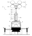
- FIG. 1 is a side view of the floodlight 1 according to the present embodiment
- FIG. 2 is a front view of the floodlight 1 according to the present embodiment
- the light projector 1 of the present embodiment is configured to include a telescopic strut 2, an elevating unit 26, dampers 27a and 27b, a lighting unit 3, a base 4, a cover 5, a pickup grip 6, and a power supply unit 7. It is sufficient that the light projector 1 according to the present invention includes at least the telescopic strut 2, the dampers 27a and 27b, the elevating unit 26, the lighting unit 3, and the base 4.
- the telescopic strut 2 is a device for raising and lowering the illuminating unit 3, and in the present embodiment is configured to include first to fifth struts 21 to 25.
- the outer diameters of the first to fifth columns 21 to 25 are sequentially reduced, and the first to fifth columns 21 to 25 are loosely fitted to each other.
- a lower end of the first pillar 21 located at the lowest position is fixed to the base 4. In FIG. 1, the lower end of the first support 21 is covered with the cover 5.
- the elevating unit 26 is a device for vertically extending and contracting the first to fifth columns in conjunction with each other.
- a handle that can be manually operated is provided on the side surface of the first support 21.
- the lighting unit 3 attached to the fifth support 25 is moved up and down with the expansion and contraction of the expandable support 2.
- the elevating mechanism of the elevating unit 26 is not limited to a portable device using a wire, and various mechanisms such as using a gear can be adopted.
- the elevating unit 26 may use not only manual operation using a handle but also driving means such as a motor and an engine.
- the dampers 27a and 27b are arranged on the left and right side surfaces of the telescopic strut 2. In the present embodiment, it is fixed so that the position below the side wall of the first support 21 and the position above the side wall of the second support 22 are connected.
- the dampers 27a and 27b have a cylinder and a piston that slides inside the cylinder.
- the dampers 27a and 27b exert a biasing force in the up-down direction, and have a function of preventing the lighting unit 3 from dropping even if an obstacle such as a break in the wire of the elevating unit 26 occurs.
- the telescopic struts 2 are arranged symmetrically with respect to the telescopic struts 2, the telescopic struts 2 can be smoothly expanded and contracted in a well-balanced manner.
- dampers 27a and 27b are provided outside, even if the dampers 27a and 27b are obstructed, they can be easily replaced. Further, since the surface condition of the piston can be easily visually recognized from the outside, it is possible to early find the above-mentioned scratches that cause gas leakage.
- the fifth support 25 is provided with an illumination section 3 for illuminating the surroundings.
- the illumination unit 3 of the present embodiment includes four lights 31a to 31d, a pedestal fixed to the fifth support 25, and a support 32 that supports the lights 31a to 31d.
- the LEDs are used for the lights 31a to 31d of the present embodiment, various light sources such as a metal halide lamp can be used in addition to the LEDs.
- the lights 31a to 31d of the present embodiment employ a directional light source for illuminating the front.
- an omnidirectional light source such as a balloon type illumination which is often used at present is used. It may be.
- the base 4 of the present embodiment is provided with two wheels to facilitate movement.
- the base 4 only needs to be a member that can fix and position the telescopic strut 2 and can perform positioning, and does not have to have wheels.
- the base 4 and the first support 21 are rotatably fixed, and by rotating the first support 21 with respect to the base 4, the direction in which the illumination unit 3 illuminates. Can be changed.
- a power supply unit 7 is provided above the base 4 and inside the cover 5.
- the power supply unit 7 is a means for supplying power to the lights 31a to 31d, and includes a power generating engine, an alternator, a fuel tank, a battery, and the like. Note that the power supply unit 7 is not limited to the form installed on the base 4 as in the present embodiment, but may be configured to be installed outside.
- a pickup grip 6 used for transporting the projector 1 is provided.
- the pickup grip 6 is firmly fixed to the base 4.
- the projector 1 can be suspended.
- the projector 1 of the present embodiment can be folded compactly during transportation or the like.
- FIG. 3A is a side view showing a standing state of the lighting unit 3
- FIG. 3B is a side view showing a housed state of the lighting unit 3.
- the support portion 32 is provided so as to be rotatable about a rotation shaft 33 a with respect to the pedestal 33.
- the lighting unit 3 is set in an upright state as shown in FIG. 3A, and when the projector 1 is carried or the like, the rotation shaft 33a is centered as shown in FIG. Then, the support portion 32 is rotated to be in the housed state.
- the height of the light projector 1 can be suppressed, and transportation and the like can be easily performed.
- the pickup grip 6 be configured such that when the illumination unit 3 is rotated, the vertically upper part thereof is opened, that is, the illumination unit 3 does not hinder the cable to be suspended. Further, since the lights 31a to 31d are heavy, when the standing state is changed from the standing state to the housed state, the position of the center of gravity of the projector 1 changes. Therefore, the position of the pickup grip 6 is preferably a position corresponding to the position of the center of gravity of the stored state. When hanging using the pickup grip 6 in the housed state, it becomes possible to hang the projector 1 in the parallel state.
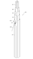
- FIG. 4 is a diagram showing a contracted state (FIG. 4A) and an extended state (FIG. 4B) of the telescopic strut 2 according to the embodiment of the present invention. 4 to 6, the illumination unit 3 located at the upper end of the fifth support 25 is illustrated as being removed.
- the first to fifth columns 21 to 25 are in the state of being accommodated in the respective interiors, and are in the shortest state.
- the lower end of the first support 21 is fixed to the base 4.
- the first column 21 is rotatable with respect to the base 4, and the direction of illumination by the illumination unit 3 can be changed.
- the telescopic strut 2 is extended upward.
- the telescopic strut 2 can be extended up to 7 m.
- the damper 27a includes a cylinder 271, a piston 272, and fixing portions 273a and 273b.
- two dampers 27a and 27b are used, and the other damper 27b is located on the opposite side of the first support 21 from the damper 27a.
- gas dampers are used for the dampers 27a and 27b, and the gas sealed in the dampers 27a and 27b can apply an urging force between the cylinder 271 and the piston 272.
- the fixing portion 273 a on the cylinder 271 side is fixed to the side wall of the second support 22.
- the fixed portion 273b on the piston 272 side is fixed to the side wall of the first support 21.
- the fixed portion 273a is fixed above the second support 22 and the fixed portion 273b is fixed below the first support 21 to maximize the amount of extension of the first support 21 and the second support 22. I have to do that.
- the first to fifth columns 21 to 25 are configured to expand and contract in conjunction with each other.
- the damper 27 a , 27b can prevent the lighting unit 3 from dropping sharply, and can prevent the lighting unit 3 from being damaged or the lighting unit 3 from colliding with a worker. It has become.
- the position of the illumination unit 3 when only the first support 21 and the second support 22 are extended be higher than the height of a general person (operator). Even if the third to fifth columns 23 to 25 drop due to a failure of the elevating unit 26, the illumination unit 3 may collide with the head of the worker or the like due to the urging force of the dampers 27a and 27b. It becomes possible to suppress.
- the lower part of the telescopic column 2 is located inside the cover 5.
- the lower side of the damper 27 a is located inside the cover 5, and it is possible to prevent foreign matter from adhering to the piston 272.
- a stretchable covering member such as a bellows shape around the piston 272.
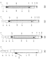
- FIG. 5 is a perspective view of the telescopic strut 2 according to the embodiment of the present invention.
- the cross-sectional shape of the first to fifth columns 21 to 25 constituting the telescopic column 2 is an octagon in which four corners of the quadrilateral are chamfered by straight lines. With such a cross-sectional shape, the first to fifth columns 21 to 25 can smoothly expand and contract without rotating carelessly.
- FIG. 6 is a view for explaining the expansion and contraction operation of the telescopic strut 2 according to the embodiment of the present invention
- FIG. 7 is a cross-sectional view of the telescopic strut 2 according to the embodiment of the present invention.
- the extension mechanism of the extension column 2 will be described with reference to FIGS.
- the first to fifth columns 21 to 25 have an octagonal cross-sectional shape in which four corners of the quadrangular shape are chamfered.
- the second support 22 is loosely fitted inside the first support 21, but the first support 21 and the second support 22 are extended and contracted by being close to each other. It is composed of an operation restricting portion (in the vicinity of the upper, right, and lower portions in FIG.
- a pulley 211 is disposed in a space formed by the space forming portion formed by the first support 21 and the second support.
- a through hole 214 for disposing the pulley 211 is provided on the wall surface of the first support 21. This is for introducing the wire 212 from the outside into the space between the first support 21 and the second support 22.
- the pulley 211 is disposed in the through hole 214 such that the rotation surface is orthogonal to the wall surface of the first support 21.
- the wire 212 introduced from the outside is hung over the pulley 211 and then lowered vertically or substantially vertically downward to be fixed to the fixing portion 213 provided on the wall surface of the second support 22.
- FIG. 6A discloses the arrangement of the wires 212.
- the second column 22 rises with respect to the first column 21.
- the first support column 21 and the second support column 22 expand and contract along the rails by the above-described expansion and contraction restricting portion, and perform smooth expansion and contraction.
- the strut 22 can extend substantially vertically upward without being greatly bent and extended.
- the pulley 211 having a sufficient size can be arranged by the space forming portion capable of securing a space of a fixed size without the space being crushed by the sliding of the first support 21 and the second support 22. Becomes Therefore, it is possible to perform a smooth movement operation by the wire 212.
- the elevation of the third column 23 accompanying the elevation of the second column 22 will be described.
- the third column 23 is loosely fitted inside the second column 22, but the second column 22 and the third column 23 are similar to the case of the first column 21 and the second column 22.
- an operation restricting unit (right and lower, near the left side in FIG. 7) that regulates the expansion and contraction operation by being brought close to each other, and a space forming unit that forms a space where the pulley 221 and the like are separated from each other. (Near the upper part of FIG. 7).
- a pulley 221 is arranged in a space formed by the space forming part of the second support 22 and the third support 23.
- the pulley 221 is fixed to an inner wall of the second support 22, and a wire 222 connecting the first support 21 and the third support 23 is bridged.
- the rotation axis of the pulley 221 is provided perpendicularly (or substantially perpendicularly) to the wall surface of the second support 22. Therefore, the rotation surface of the pulley 221 is arranged along the wall surface of the second support 22, and the pulley 221 having a sufficient size can be disposed without necessity of making the second support 22 inadvertently thick. Is possible.
- the wire 222 bridged over the pulley 221 has one end fixed to a fixing portion 224 provided below the first column 21 and the other end fixed to a side surface of the third column 23. 223.
- the wire 222 is disposed so as to descend substantially perpendicularly from the pulley 221 to the fixed part 223 or the fixed part 224. Such an arrangement of the wire 222 enables the wire 222 and the pulley 221 to move smoothly.
- the wire 222 and the pulley 221 are arranged in a space (a space formed by the space forming part) that is not hindered by expansion and contraction of the second support 22 and the third support 23, This makes it possible to smoothly expand and contract the third support column 23, and to prevent the pulley 221 and the like from breaking down due to repeated sliding, or to suppress problems such as the wire 222 being cut due to repeated sliding.
- the second support column 22 is raised by pulling the wire 212 from the outside.
- the pulley 221 provided on the second support 22 rises as the second support 22 rises, and the wire 222 bridged over the pulley 221 becomes the third pulley.
- the fixing portion 223 fixed to the column 23 rises.
- the lifting and lowering of the fourth column 24 accompanying the lifting and lowering of the third column 23 will be described.
- the fourth column 24 is loosely fitted inside the third column 23, but the third column 23 and the fourth column are similar to the case of the first column 21 and the second column 22.
- an operation restricting unit in the lower, left, and right vicinity in FIG. 7 that restricts the expansion and contraction operation by being brought close to each other, and a space forming unit that forms a space in which the pulley 231 and the like are separated from each other. (Near the right side of FIG. 7).
- a pulley 231 is disposed in a space formed by the space forming portion formed by the third support 23 and the fourth support 24.
- the pulley 231 is fixed to the inner wall of the third support 23, and a wire 232 connecting the second support 22 and the fourth support 24 is bridged.
- the rotation axis of the pulley 231 is provided perpendicularly (or substantially perpendicularly) to the wall surface of the third support column 23. Therefore, the rotation surface of the pulley 231 is disposed along the wall surface of the third support 23, and the pulley 231 having a sufficient size can be disposed without necessitating the third support 23 to be inadvertently thickened. Is possible.
- the wire 232 bridged over the pulley 231 has one end fixed to a fixing portion 234 provided below the second support 22, and the other end fixed to a side surface of the fourth support 24. 233.
- the wire 232 is disposed so as to descend substantially perpendicularly from the pulley 231 to the fixed portion 233 or the fixed portion 234.
- the third column 23 rises in conjunction with the pulling of the wire 212.
- the pulley 231 provided on the third support 23 rises in accordance with the rise of the third support 23, and the wire 232 bridged over the pulley 231 is connected to the fourth support 23.
- the fourth column 24 rises.
- the fourth support 24 is loosely fitted inside the fifth support 25, but the fourth support 24 and the fifth support 25 are similar to the case of the first support 21 and the second support 22.
- an operation restricting unit in the vicinity of the left, upper, and right sides in FIG. 7 that restricts the expansion and contraction operation by being close to each other, and a space forming unit that forms a space separated from each other and provided with a pulley 241 and the like. (Near the lower part of FIG. 7).
- a pulley 241 is arranged in a space formed by the space forming part of the fourth support 24 and the fifth support 25.
- the pulley 241 is fixed to the inner wall of the fourth support 24, and a wire 242 connecting the third support 23 and the fifth support 25 is bridged.
- the rotation axis of the pulley 241 is provided perpendicularly (or substantially perpendicularly) to the wall surface of the fourth support 24. Therefore, the rotating surface of the pulley 241 is disposed along the wall surface of the fourth support 24, and the pulley 241 having a sufficient size can be disposed without necessitating the fourth support 24 to be inadvertently thickened. Is possible.
- the wire 242 bridged over the pulley 241 has one end fixed to a fixing portion 244 provided below the third support 23 and the other end fixed to a side surface of the fifth support 25. 243.
- the wire 242 is disposed so as to descend substantially perpendicularly from the pulley 241 to the fixed portion 243 or the fixed portion 244.
- the fourth column 24 rises in conjunction with the pulling of the wire 212.
- the pulley 241 provided on the fourth support 24 rises in accordance with the rise of the fourth support 24, and the wire 242 bridged over the pulley 241 becomes the fifth pulley 241.
- the fifth column 25 rises.
- the wire 212 exposed to the outside of the telescopic strut 2 is wound by the drum provided on the elevating unit 26,
- the second support 22 rises.
- the third support 23, the fourth support 24, and the fifth support 25 move upward in conjunction with each other.
- the operation restricting portion between the adjacent first to fifth columns 21 to 25, such as the first column 21 and the second column 22 the sliding of the columns is smooth and It is possible to move vertically (or almost vertically).
- the pulleys 211, 221, 231, and 241 are arranged in a space that is not hindered by sliding of the first to fifth columns 21 to 25, so that a smooth lifting operation can be performed.
- the spatial positions formed by the space forming portions are arranged at different positions on the cross-sectional circumference of the telescopic strut 2 (the space formed by the first struts 21 and the second struts 22). Is the left side of FIG. 7, the space formed by the second support 22 and the third support 23 is above FIG. 7, and the space formed by the third support 23 and the fourth support 24 is 7 and the space formed by the fourth support 24 and the fifth support 25 is below FIG. 7), so that the telescopic support 2 is not unnecessarily thickened, and 2 can be expanded and contracted in a well-balanced manner.
- the expansion and contraction mechanism of the telescopic strut 2 used in the floodlight 1 of the present embodiment has been described.
- the sliding can be performed smoothly and vertically (or substantially vertically), and the sliding portion is formed by the space forming portion.
- the operations of these members are operated without being hindered by expansion and contraction, and smooth expansion and contraction And it is possible to suppress a failure of a member that performs expansion and contraction operations, such as a pulley and a wire.
- the dampers 27a and 27b are provided between the first support 21 and the second support 22, so that the vertical direction of the second support 22 with respect to the first support 21 is regulated in an appropriate direction. 2 makes the lifting and lowering smoother.
- each of the first to fifth columns 21 to 25 uses an octagonal cross-sectional shape in which four corners of a quadrangular shape are chamfered.
- the cross-sectional shape is not limited to such a shape, and may be a polygon having five or more pentagons. Alternatively, it may be configured in a shape having a curved surface.
- the telescopic strut 2 that raises and lowers the illumination unit 3 in the floodlight 1 has been described. It can also be an object.
Abstract
【課題】投光器で使用される伸縮支柱を円滑に昇降させることを1つの目的とする。 【解決手段】本発明に係る投光器は、外径を順次小さくした複数の支柱(21)~(25)を有し、支柱(21)~(25)が遊嵌され、上下方向に伸縮可能な伸縮支柱(2)と、最も内側に位置する支柱(25)に取り付けられた照明部(3)と、支柱(21)~(25)を連動して上下方向に伸縮させる昇降部(26)と、最も外側に位置する支柱(21)が固定される基台(4)と、最も外側に位置する支柱(21)の側面と、2番目に外側に位置する支柱(22)の側面を接続するダンパー(27a)、(27b)と、を備える。
Description
本発明は、道路工事、建設工事、各種イベント等において周囲の照明を行う投光器であって、特に台車などの基台に設置される伸縮支柱を備える投光器に関する。
道路工事、建設工事、各種イベントにおいて周囲を照明する投光器は、照明範囲を広範囲とする場合、できるだけ高い位置から照明を行うことが好ましい。そのため、投光器は照明手段の高さを調整するための伸縮支柱を備えたものが使用されることがある。
特許文献1には、照明手段の高さを変更可能な伸縮支柱を有する投光器が開示されている。この伸縮支柱の内部には付勢手段としてのダンパーが設けられている。ダンパーの一端は、第1の支柱に固定され、他端は第2の支柱に固定されている。そして、ダンパーの先端には、第1の支柱と第3の支柱間に架け渡されたワイヤを摺動させる滑車が設けられている。このような構成により、第2の支柱を伸縮させることで、伸縮支柱全体が連動して伸縮することになる。また、第1~第3の支柱が円管で構成されるものの、上記構成により支柱の回転位置を気にすることなく支柱の伸縮を行うことが可能となっている。
ところで、特許文献1に記載の投光器で使用される伸縮支柱は、伸縮に付勢力を与えるためのダンパーが伸縮支柱内部に配置されている。ダンパーとしては、例えば、ガスダンパーを使用することが考えられるが、経年により内部のガスが抜けることによる不勢力が低下することが考えられる。このようにダンパーに支障が生じた場合には、伸縮支柱を解体する等、大がかりな修理が必要となる。また、ダンパーのロッドが傷付いた場合には、内部のガスが抜けやすくなることも考えられる。しかしながら、外部からロッドの様子を観察することは困難な状況にあった。
(第1-1の構成)
本発明に係る投光器は、このような課題を解決することを一つの目的とし、伸縮時に付勢力を与えるダンパーのメンテナンスを容易にするとともに、ダンパーを外部から観察し易い状況とし、付勢力の低下等を事前に防ぐため、以下の構成を採用するものである。
外径を順次小さくした複数の支柱を有し、前記支柱が遊嵌され、上下方向に伸縮可能な伸縮支柱と、
最も内側に位置する前記支柱に取り付けられた照明部と、
前記支柱を連動して上下方向に伸縮させる昇降部と、
最も外側に位置する前記支柱が固定される基台と、
最も外側に位置する前記支柱の側面と、2番目に外側に位置する前記支柱の側面を接続するダンパーと、を備える。
本発明に係る投光器は、このような課題を解決することを一つの目的とし、伸縮時に付勢力を与えるダンパーのメンテナンスを容易にするとともに、ダンパーを外部から観察し易い状況とし、付勢力の低下等を事前に防ぐため、以下の構成を採用するものである。
外径を順次小さくした複数の支柱を有し、前記支柱が遊嵌され、上下方向に伸縮可能な伸縮支柱と、
最も内側に位置する前記支柱に取り付けられた照明部と、
前記支柱を連動して上下方向に伸縮させる昇降部と、
最も外側に位置する前記支柱が固定される基台と、
最も外側に位置する前記支柱の側面と、2番目に外側に位置する前記支柱の側面を接続するダンパーと、を備える。
(第1-2の構成)
さらに本発明に係る投光器において、
前記ダンパーは、シリンダーと、前記シリンダー部内に収容されるピストンを有し、
前記ピストン側は、最も外側に位置する前記支柱の側面に固定され、
前記シリンダー側は、2番目に外側に位置する前記支柱の側面に固定されている。
さらに本発明に係る投光器において、
前記ダンパーは、シリンダーと、前記シリンダー部内に収容されるピストンを有し、
前記ピストン側は、最も外側に位置する前記支柱の側面に固定され、
前記シリンダー側は、2番目に外側に位置する前記支柱の側面に固定されている。
(第1-3の構成)
さらに本発明に係る投光器において、
前記ダンパーの下方は、カバー内に位置している。
さらに本発明に係る投光器において、
前記ダンパーの下方は、カバー内に位置している。
(第1-4の構成)
さらに本発明に係る投光器において、
前記ダンパーは、複数設けられている。
さらに本発明に係る投光器において、
前記ダンパーは、複数設けられている。
(第1-5の構成)
さらに本発明に係る投光器において、
隣接する前記支柱間において、断面上、動作規制部と空間形成部が形成され、
前記動作規制部は、外側に位置する支柱に対して内側に位置する支柱が近接し、伸縮動作を規制し、
前記空間形成部は、外側に位置する支柱に対して内側に位置する支柱が離間し、伸縮動作を行う部材が配置されている。
さらに本発明に係る投光器において、
隣接する前記支柱間において、断面上、動作規制部と空間形成部が形成され、
前記動作規制部は、外側に位置する支柱に対して内側に位置する支柱が近接し、伸縮動作を規制し、
前記空間形成部は、外側に位置する支柱に対して内側に位置する支柱が離間し、伸縮動作を行う部材が配置されている。
(第2-1の構成)
また、本発明は投光器のみならず、各種部材を昇降させる伸縮支柱のみを発明の客体としてもよい。そのため、本発明に係る伸縮支柱は、以下の構成を採用するものである。
外径を順次小さくした複数の支柱を有し、前記支柱が遊嵌され、上下方向に伸縮可能な伸縮支柱を有し、
隣接する前記支柱間において、断面上、動作規制部と空間形成部が形成され、
前記動作規制部は、外側に位置する支柱に対して内側に位置する支柱が近接し、伸縮動作を規制し、
前記空間形成部は、外側に位置する支柱に対して内側に位置する支柱が離間し、伸縮動作を行う部材が配置されている。
また、本発明は投光器のみならず、各種部材を昇降させる伸縮支柱のみを発明の客体としてもよい。そのため、本発明に係る伸縮支柱は、以下の構成を採用するものである。
外径を順次小さくした複数の支柱を有し、前記支柱が遊嵌され、上下方向に伸縮可能な伸縮支柱を有し、
隣接する前記支柱間において、断面上、動作規制部と空間形成部が形成され、
前記動作規制部は、外側に位置する支柱に対して内側に位置する支柱が近接し、伸縮動作を規制し、
前記空間形成部は、外側に位置する支柱に対して内側に位置する支柱が離間し、伸縮動作を行う部材が配置されている。
(第2-2の構成)
さらに、第2-1の構成に係る伸縮支柱は、
前記空間形成部で形成された空間の外側に位置する前記支柱の内壁に配置された滑車と、
前記滑車に架け渡され、前記空間の内側に位置する前記支柱と、前記滑車が設けられた前記支柱の更に外側に位置する前記支柱を接続するワイヤと、を有する。
さらに、第2-1の構成に係る伸縮支柱は、
前記空間形成部で形成された空間の外側に位置する前記支柱の内壁に配置された滑車と、
前記滑車に架け渡され、前記空間の内側に位置する前記支柱と、前記滑車が設けられた前記支柱の更に外側に位置する前記支柱を接続するワイヤと、を有する。
(第2-3の構成)
さらに、第2-2の構成に係る伸縮支柱において、
前記滑車の回転軸は、前記支柱の壁面に垂直もしくは略垂直に設けられている。
さらに、第2-2の構成に係る伸縮支柱において、
前記滑車の回転軸は、前記支柱の壁面に垂直もしくは略垂直に設けられている。
(第2-4の構成)
さらに、第2-1の構成に係る伸縮支柱において、
前記空間形成部は、隣接する前記支柱間毎に複数設けられ、
前記空間形成部は、前記支柱の断面円周上、異なる位置に設けられている。
さらに、第2-1の構成に係る伸縮支柱において、
前記空間形成部は、隣接する前記支柱間毎に複数設けられ、
前記空間形成部は、前記支柱の断面円周上、異なる位置に設けられている。
(第2-5の構成)
さらに、第2-1の構成に係る伸縮支柱は、
最も外側に位置する前記支柱の側面と、2番目に外側に位置する前記支柱の側面を接続するダンパーを備える。
さらに、第2-1の構成に係る伸縮支柱は、
最も外側に位置する前記支柱の側面と、2番目に外側に位置する前記支柱の側面を接続するダンパーを備える。
本発明に係る投光器によれば、伸縮支柱にダンパーを設けたことで、伸縮支柱の伸縮動作を円滑に行うことが可能となる。また、ダンパーは、伸縮支柱の外部に設けられているため、ダンパーの交換等、各種メンテナンスも容易となる。そして、ダンパーのロッドに生じた傷等を早期発見することも可能となり、ダンパーに生じる不具合を事前に防ぐことも可能となる。
また、本発明に係る伸縮支柱は、隣り合っている支柱間に、動作規制部、空間形成部を設けたことで、支柱の摺動を滑らか、かつ、垂直(あるいは略垂直)に行うことを可能とし、空間形成部で形成された空間に滑車、ワイヤ等、伸縮動作を行う部材を収容することで、これら部材の動作を伸縮に阻害されることなく動作させ、円滑な伸縮を可能とし、滑車やワイヤ等、伸縮動作を行う部材の故障を抑制することを可能としている。
図1は、本実施形態に係る投光器1の側面図であり、図2は、本実施形態に係る投光器1の正面図である。本実施形態の投光器1は、伸縮支柱2、昇降部26、ダンパー27a、27b、照明部3、基台4、カバー5、ピックアップグリップ6、電源部7を備えて構成されている。なお、本発明に係る投光器1としては、少なくとも伸縮支柱2、ダンパー27a、27b、昇降部26、照明部3、基台4を備えていれば足りるものである。
伸縮支柱2は、照明部3を上下させる装置であって、本実施形態では第1~第5支柱21~25を有して構成されている。第1~第5支柱21~25は、その外径が順次小さく構成されており、互いに遊嵌された状態となっている。最も下方に位置する第1支柱21は、その下端が基台4に固定されている。なお、図1では、第1支柱21の下端はカバー5で覆われた状態となっている。
昇降部26は、第1~第5支柱が連動して上下方向に伸縮させる装置である。本実施形態では、第1支柱21の側面に、手動操作可能なハンドルが設けられている。ハンドルを操作することで、伸縮支柱2の内部に設けられたワイヤの長さを調整し、伸縮支柱2を上下方向に伸縮させることが可能である。伸縮支柱2の伸縮に伴い、第5支柱25に取り付けられた照明部3を上下させる。昇降部26の昇降機構は、ワイヤを使用する携帯に限られるものではなく、ギアを使用する等、各種機構を採用することが可能である。また、昇降部26は、ハンドルを使用した手動操作のみならず、モータ、エンジン等の駆動手段を使用するものであってもよい。
ダンパー27a、27bは伸縮支柱2の左右側面に配置されている。本実施形態では、第1支柱21の側壁の下方位置と、第2支柱22の側壁の上方位置を接続するように固定されている。ダンパー27a、27bは、シリンダーとシリンダー内部で摺動するピストンを有して構成される。ダンパー27a、27bは、上下方向に付勢力を作用させ、万が一、昇降部26のワイヤが切れる等の障害が発生した場合でも、照明部3が落下することを抑制する機能を有する。また、伸縮支柱2を挟んで対称位置に配置されているため、伸縮支柱2を、バランスよく滑らかに伸縮させることを可能としている。
ダンパー27a、27bには、ガスを使用したガスダンパーを使用することが考えられるが、ガスダンパーを使用する場合、ピストンに石や砂等の異物が付着したまま摺動させると、ピストンに傷が付き、傷から付勢力を働かせるためのガスが抜け、付勢力が無くなる、あるいは弱くなることが考えられる。そのため、本実施形態では、シリンダーが上方に、ピストンが下方に位置するように配置している。このように配置することで、カバー5内にピストンが配置されることとなり、ピストンを異物から保護することが容易となっている。
また、本実施形態では、ダンパー27a、27bは、外部に設けられているため、ダンパー27a、27bに支障が生じた場合であっても容易に交換を行うことが可能となっている。さらに、ピストンの表面状態も外部から容易に視認することもできるため、上述したようなガス抜けの原因となる傷も早期に発見することが可能となっている。
第5支柱25には、周囲を照明するための照明部3が設けられている。本実施形態の照明部3は、4個のライト31a~31d、第5支柱25に固定された台座、ライト31a~31dを支える支持部32を有して構成されている。本実施形態のライト31a~31dにはLEDを使用しているが、LEDの他、メタルハライドランプ等、各種光源を使用することが可能である。また、本実施形態のライト31a~31dは、前方を照明する指向性のある光源を採用しているが、現在、よく使用されるバルーン型照明のように、無指向性の光源を使用することとしてもよい。
本実施形態の基台4は、移動を容易にするため2つの車輪を備えて構成されている。基台4は、伸縮支柱2を固定し、位置決めを行うことが可能な部材であればよく、車輪を有することを必須とするものではない。また、本実施形態では、基台4と第1支柱21は、回動可能に固定されており、基台4に対して第1支柱21を回動させることで、照明部3が照明する方向を変更することが可能となっている。基台4の上部であって、カバー5内部には、電源部7が設けられている。電源部7は、ライト31a~31dに電源を供給する手段であって、発電用のエンジン、オルタネーター、燃料タンク、バッテリー等を有して構成される。なお、電源部7は、本実施形態のように基台4に設置される形態に限られるものではなく、外部に設置される構成であってもよい。
カバー5の上方には、投光器1を運搬する際に使用するピックアップグリップ6が設けられている。ピックアップグリップ6は、基台4にしっかりと固定されている。ピックアップグリップ6にクレーンのフック等を掛けることで、投光器1を吊荷することが可能となっている。ところで、本実施形態の投光器1は、運搬時等において、コンパクトに折り畳むことが可能となっている。
図3(A)は、照明部3の起立状態を示す側面図であり、図3(B)は、照明部3の収納状態を示す側面図である。支持部32は、台座33に対して回動軸33aを中心として回動可能に設けられている。投光器1を使用する際等には、図3(A)のように照明部3を起立状態とし、投光器1を運搬する際等には、図3(B)のように回動軸33aを中心として支持部32を回動させて収納状態とする。このように収納状態とすることで、投光器1の高さを抑え、運搬等を容易に行うことが可能となる。
また、ピックアップグリップ6は、照明部3を回動させた際、その鉛直上方が開けた状態、すなわち、照明部3は、吊荷するケーブルの障害とならないような構成とすることが好ましい。また、ライト31a~31dは、重量もあるため、起立状態から収納状態にすると、投光器1の重心位置が変化する。そのため、ピックアップグリップ6の位置は、収納状態の重心位置に対応した位置とすることが好ましい。収納状態でピックアップグリップ6を使用して吊荷する際、投光器1を平行状態のままで吊荷することが可能となる。
次に、本実施形態の伸縮支柱2について、その伸縮構造を詳細に説明する。図4は、本発明の実施形態に係る伸縮支柱2の収縮状態(図4(A))と伸長状態(図4(B))を示す図である。なお、図4~図6において、第5支柱25の上端に位置する照明部3は、取り外した状態として記載している。
図4(A)に示されるように、収縮状態では、第1~第5支柱21~25は、それぞれの内部に収まった状態となっており、最も短い状態となっている。また、第1支柱21の下端は基台4に固定されている。本実施形態では、第1支柱21は、基台4に対して回動可能とされており、照明部3による照明方向を変更することが可能となっている。また、図4(B)に示す伸長状態では、伸縮支柱2を上方向に延ばした状態となっている。なお、本実施形態では、伸縮支柱2を最大7mまで延ばすことが可能となっている。
ダンパー27aは、シリンダー271、ピストン272、固定部273a、273bを有して構成されている。なお、本実施形態では2つのダンパー27a、27bを使用しており、もう一つのダンパー27bは、第1支柱21を挟んで、ダンパー27aと反対側に位置している。本実施形態では、ダンパー27a、27bにガスダンパーを使用しており、ダンパー27a、27b内に封入されたガスにより、シリンダー271、ピストン272間で付勢力を作用させることが可能となっている。
シリンダー271側の固定部273aは、第2支柱22の側壁に固定されている。また、ピストン272側の固定部273bは第1支柱21の側壁に固定されている。本実施形態では、固定部273aを第2支柱22の上方に、固定部273bを第1支柱21の下方に固定することで、第1支柱21と第2支柱22の伸びる量を最大限に活かすこととしている。本実施形態では、第1~第5支柱21~25が連動して伸縮する構成としているが、例えば、昇降部26で使用するワイヤが切れる等の不具合が生じた場合であっても、ダンパー27a、27bの付勢力により、照明部3が急激に落下することを防ぐことが可能となっており、照明部3の損傷、あるいは、照明部3が作業員に衝突することを抑制することが可能となっている。
なお、第1支柱21と第2支柱22のみを延ばしたときの照明部3の位置は、一般的な人(作業員)の高さよりも高くしておくことが好ましい。昇降部26の不具合等により、第3~第5支柱23~25が落下した場合であっても、ダンパー27a、27bの付勢力により、照明部3が作業員等の頭部に衝突することを抑制することが可能となる。
伸縮支柱2の下方は、カバー5の内部に位置している。このような構成により、図4(A)の収縮時には、ダンパー27aの下方は、カバー5内に位置することになり、ピストン272に異物が付着することを抑制できる。また、図4(B)の伸張時には、カバー5からピストン272が露出することになるため、ピストン272の周囲には、蛇腹状等、伸縮可能な被覆部材を設けておくことが更に好ましい。
図5は、本発明の実施形態に係る伸縮支柱2の斜視図である。本実施形態において、伸縮支柱2を構成する第1~第5支柱21~25の断面形状は、4角形状の4隅を直線で面取りした8角形状となっている。このような断面形状により、第1~第5支柱21~25が不用意に回転することなく、円滑に伸縮動作を行うことが可能となっている。
図6は、本発明の実施形態に係る伸縮支柱2の伸縮動作を説明するための図であり、図7は、本発明の実施形態に係る伸縮支柱2の断面図を示している。図6、図7を使用して伸縮支柱2の伸縮機構を説明する。図5で説明したように、第1~第5支柱21~25は、4角形状の4隅が面取りされた8角形状の断面形状を有している。図7に示されるように、第1支柱21の内側には第2支柱22が遊嵌しているが、第1支柱21と第2支柱22の間は、互いに近接されることで伸縮動作を規制する動作規制部(図7の上方、右方、下方近傍)と、互いに離間して滑車211等を設ける空間を形成する空間形成部(図7の左方近傍)で構成されている。動作規制部が設けられることで、伸縮動作を規制して第1支柱21と第2支柱の伸縮を滑らかに行うことを可能とするとともに、空間形成部で形成される空間が、第1支柱21と第2支柱の移動により潰されることなく、一定量の空間を保つことを可能としている。
第1支柱21と第2支柱による空間形成部が形成する空間内には、滑車211が配置されている。第1支柱21の壁面には、滑車211を配設するための貫通孔214が設けられている。これは、ワイヤ212を外部から第1支柱21と第2支柱22の間の空間に導入するためである。滑車211は、貫通孔214にその回転面が第1支柱21の壁面に直交するように配置されている。外部から導入されるワイヤ212は、滑車211に架け渡された後、垂直下方あるいは略垂直下方に降下され、第2支柱22の壁面に設けられた固定部213に固定される。
図6(A)には、ワイヤ212の配置の様子が開示されている。ワイヤ212を外部から引くことで、第1支柱21に対して第2支柱22が上昇することになる。その際、前述した伸縮規制部により、第1支柱21と第2支柱22は、レールを沿うように伸縮することになり、滑らかな伸縮を行うこと、そして、第1支柱21に対して第2支柱22が大きく曲がって伸長することなく、略鉛直上方に伸長することが可能となっている。また、第1支柱21と第2支柱22の摺動により空間が潰されることなく、一定の大きさの空間を担保可能な空間形成部により、十分な大きさの滑車211を配置することが可能となる。そのため、ワイヤ212による滑らかな移動動作を行うことが可能となっている。
次に、第2支柱22の昇降に伴う、第3支柱23の昇降について説明を行う。図7に示されるように、第2支柱22の内側には第3支柱23が遊嵌しているが、第1支柱21と第2支柱22の場合と同様、第2支柱22と第3支柱23の間は、互いに近接されることで伸縮動作を規制する動作規制部(図7の右方、下方、左方近傍)と、互いに離間して滑車221等を設ける空間を形成する空間形成部(図7の上方近傍)で構成されている。
第2支柱22と第3支柱23による空間形成部で形成される空間には、滑車221が配置されている。滑車221は、第2支柱22の内壁に固定され、第1支柱21と第3支柱23を接続するワイヤ222が架け渡されている。ここで、滑車221の回転軸は、第2支柱22の壁面に垂直(あるいは略垂直)に設けられている。したがって、滑車221の回転面は、第2支柱22の壁面に沿うように配置されることになり、第2支柱22を不用意に太くする必要なく、十分な大きさの滑車221を配置することが可能となっている。
また、滑車221に架け渡されるワイヤ222は、一方の端が第1支柱21の下方に設けられた固定部224に固定され、他方の端が、第3支柱23の側面に設けられた固定部223に固定されている。また、図6(B)、図7から分かるように、ワイヤ222は、滑車221から固定部223、あるいは、固定部224に対して、略垂直に下降するように配置されている。このようなワイヤ222の配置によって、ワイヤ222、滑車221を滑らかに移動させることを可能としている。また、ワイヤ222、滑車221は、第2支柱22、第3支柱23の伸縮によって阻害されることのない空間(空間形成部によって形成される空間)に配置されているため、第2支柱22、第3支柱23の伸縮を円滑に行うこと、並びに、滑車221等が度重なる摺動により故障すること、あるいは、度重なる摺動によりワイヤ222が切れる等の不具合を抑制することを可能としている。
図6(A)で説明したように、ワイヤ212を外部から引くことで、第2支柱22が上昇することになる。図6(B)を参照するに、第2支柱22の上昇に応じて、第2支柱22に設けられた滑車221が上昇することになり、滑車221に架け渡されたワイヤ222が、第3支柱23に固定された固定部223を引き上げることによって第3支柱23が上昇を行う。
次に、第3支柱23の昇降に伴う、第4支柱24の昇降について説明を行う。図7に示されるように、第3支柱23の内側には第4支柱24が遊嵌しているが、第1支柱21と第2支柱22の場合と同様、第3支柱23と第4支柱24の間は、互いに近接されることで伸縮動作を規制する動作規制部(図7の下方、左方、右方近傍)と、互いに離間して滑車231等を設ける空間を形成する空間形成部(図7の右方近傍)で構成されている。
第3支柱23と第4支柱24による空間形成部で形成される空間には、滑車231が配置されている。滑車231は、第3支柱23の内壁に固定され、第2支柱22と第4支柱24を接続するワイヤ232が架け渡されている。ここで、滑車231の回転軸は、第3支柱23の壁面に垂直(あるいは略垂直)に設けられている。したがって、滑車231の回転面は、第3支柱23の壁面に沿うように配置されることになり、第3支柱23を不用意に太くする必要なく、十分な大きさの滑車231を配置することが可能となっている。
また、滑車231に架け渡されるワイヤ232は、一方の端が第2支柱22の下方に設けられた固定部234に固定され、他方の端が、第4支柱24の側面に設けられた固定部233に固定されている。また、図6(C)、図7から分かるように、ワイヤ232は、滑車231から固定部233、あるいは、固定部234に対して、略垂直に下降するように配置されている。
図6(A)、図6(B)で説明したように、ワイヤ212が引かれることに連動して、第3支柱23が上昇することになる。図6(C)を参照するに、第3支柱23の上昇に応じて、第3支柱23に設けられた滑車231が上昇することになり、滑車231に架け渡されたワイヤ232が、第4支柱24に固定された固定部233を引き上げることによって第4支柱24が上昇を行う。
次に、第4支柱24の昇降に伴う、第5支柱25の昇降について説明を行う。図7に示されるように、第5支柱25の内側には第4支柱24が遊嵌しているが、第1支柱21と第2支柱22の場合と同様、第4支柱24と第5支柱25の間は、互いに近接されることで伸縮動作を規制する動作規制部(図7の左方、上方、右方近傍)と、互いに離間して滑車241等を設ける空間を形成する空間形成部(図7の下方近傍)で構成されている。
第4支柱24と第5支柱25による空間形成部で形成される空間には、滑車241が配置されている。滑車241は、第4支柱24の内壁に固定され、第3支柱23と第5支柱25を接続するワイヤ242が架け渡されている。ここで、滑車241の回転軸は、第4支柱24の壁面に垂直(あるいは略垂直)に設けられている。したがって、滑車241の回転面は、第4支柱24の壁面に沿うように配置されることになり、第4支柱24を不用意に太くする必要なく、十分な大きさの滑車241を配置することが可能となっている。
また、滑車241に架け渡されるワイヤ242は、一方の端が第3支柱23の下方に設けられた固定部244に固定され、他方の端が、第5支柱25の側面に設けられた固定部243に固定されている。また、図6(D)、図7から分かるように、ワイヤ242は、滑車241から固定部243、あるいは、固定部244に対して、略垂直に下降するように配置されている。
図6(A)~図6(C)で説明したように、ワイヤ212が引かれることに連動して、第4支柱24が上昇することになる。図6(D)を参照するに、第4支柱24の上昇に応じて、第4支柱24に設けられた滑車241が上昇することになり、滑車241に架け渡されたワイヤ242が、第5支柱25に固定された固定部243を引き上げることによって第5支柱25が上昇を行う。
以上、図6(A)~図6(D)、図7を用いて説明したように、伸縮支柱2の外部に露出したワイヤ212を、昇降部26に設けられたドラムで巻き取ることで、第2支柱22が上昇する。そして、第2支柱22の上昇に応じて、第3支柱23、第4支柱24、第5支柱25が連動して上昇する。本実施形態では、第1支柱21と第2支柱22等、隣り合っている第1~第5支柱21~25間に、動作規制部が設けられることで、支柱の摺動を滑らか、かつ、垂直(あるいは略垂直)に昇降させることを可能としている。また、空間形成部を設けることで、第1~第5支柱21~25の摺動に阻害されない空間に滑車211、221、231、241を配置して、円滑な昇降動作を可能としている。
なお、図7に示されるように、空間形成部によって形成される空間位置を、伸縮支柱2の断面円周上、異なる位置に配置する(第1支柱21と第2支柱22によって形成される空間は、図7の左方であり、第2支柱22と第3支柱23によって形成される空間は、図7の上方であり、第3支柱23と第4支柱24によって形成される空間は、図7の右方であり、第4支柱24と第5支柱25によって形成される空間は、図7の下方である。)ことにより、伸縮支柱2が不必要に太くならないようにするとともに、伸縮支柱2をバランスよく伸縮させることが可能となっている。
以上、本実施形態の投光器1で使用される伸縮支柱2について、その伸縮機構を説明したが、本実施形態の伸縮支柱2は、図7の断面に示されるように、隣り合っている第1~第5支柱21~25間に、動作規制部、空間形成部を設けたことで、摺動を滑らか、かつ、垂直(あるいは略垂直)に行うことを可能とし、空間形成部で形成された空間に滑車211、221、231、241、ワイヤ212、222、232、242等、伸縮動作を行う部材を収容することで、これら部材の動作を伸縮に阻害されることなく動作させ、円滑な伸縮を可能とし、滑車やワイヤ等、伸縮動作を行う部材の故障を抑制することを可能としている。また、本実施形態では、第1支柱21と第2支柱22間にダンパー27a、27bを設けたことで、第1支柱21に対する第2支柱22の昇降方向を適切な方向に規制し、伸縮支柱2の昇降を更に円滑なものとしている。
なお、本実施形態では、図7に示されるように、第1~第5支柱21~25は、その断面として、4角形状の4隅が面取りされた8角形状の断面形状を使用して、動作規制部、空間形成部を実現しているが、断面の形状は、このような形状に限られるものではなく、5角形以上の多角形であってもよい。あるいは、曲面を有する形状で構成することとしても構わない。
また、本実施形態では、投光器1において、照明部3を上昇、下降させる伸縮支柱2について説明を行ったが、伸縮支柱2は、投光器1以外に適用する、すなわち伸縮支柱2を単体として発明の客体とすることも可能である。
1:投光器
2:伸縮支柱
3:照明部
4:基台
5:カバー
6:ピックアップグリップ
7:電源部
21~25:第1~第5支柱
26:昇降部
27a、27b:ダンパー
31a~31d:ライト
32:支持部
33:台座
33a:回動軸
211、221、231、241:滑車
212、222、232、242:ワイヤ
213、223、233、243:固定部
214、224、234、244:固定部
214:貫通孔
271:シリンダー
272:ピストン
273a、273b:固定部
2:伸縮支柱
3:照明部
4:基台
5:カバー
6:ピックアップグリップ
7:電源部
21~25:第1~第5支柱
26:昇降部
27a、27b:ダンパー
31a~31d:ライト
32:支持部
33:台座
33a:回動軸
211、221、231、241:滑車
212、222、232、242:ワイヤ
213、223、233、243:固定部
214、224、234、244:固定部
214:貫通孔
271:シリンダー
272:ピストン
273a、273b:固定部
Claims (5)
- 外径を順次小さくした複数の支柱を有し、前記支柱が遊嵌され、上下方向に伸縮可能な伸縮支柱と、
最も内側に位置する前記支柱に取り付けられた照明部と、
前記支柱を連動して上下方向に伸縮させる昇降部と、
最も外側に位置する前記支柱が固定される基台と、
最も外側に位置する前記支柱の側面と、2番目に外側に位置する前記支柱の側面を接続するダンパーと、を備える
投光器。 - 前記ダンパーは、シリンダーと、前記シリンダー部内に収容されるピストンを有し、
前記ピストン側は、最も外側に位置する前記支柱の側面に固定され、
前記シリンダー側は、2番目に外側に位置する前記支柱の側面に固定されている
請求項1に記載の投光器。 - 前記ダンパーの下方は、カバー内に位置している
請求項2に記載の投光器。 - 前記ダンパーは、複数設けられている
請求項1に記載の投光器。 - 隣接する前記支柱間において、断面上、動作規制部と空間形成部が形成され、
前記動作規制部は、外側に位置する支柱に対して内側に位置する支柱が近接し、伸縮動作を規制し、
前記空間形成部は、外側に位置する支柱に対して内側に位置する支柱が離間し、伸縮動作を行う部材が配置されている
請求項1に記載の投光器。
Priority Applications (2)
| Application Number | Priority Date | Filing Date | Title |
|---|---|---|---|
| EP19851044.8A EP3842690A4 (en) | 2018-08-24 | 2019-07-31 | PROJECTOR |
| US17/269,882 US11402086B2 (en) | 2018-08-24 | 2019-07-31 | Floodlight |
Applications Claiming Priority (2)
| Application Number | Priority Date | Filing Date | Title |
|---|---|---|---|
| JP2018156931A JP6906797B2 (ja) | 2018-08-24 | 2018-08-24 | 投光器 |
| JP2018-156931 | 2018-08-24 |
Publications (1)
| Publication Number | Publication Date |
|---|---|
| WO2020039870A1 true WO2020039870A1 (ja) | 2020-02-27 |
Family
ID=69592994
Family Applications (1)
| Application Number | Title | Priority Date | Filing Date |
|---|---|---|---|
| PCT/JP2019/030087 WO2020039870A1 (ja) | 2018-08-24 | 2019-07-31 | 投光器 |
Country Status (4)
| Country | Link |
|---|---|
| US (1) | US11402086B2 (ja) |
| EP (1) | EP3842690A4 (ja) |
| JP (1) | JP6906797B2 (ja) |
| WO (1) | WO2020039870A1 (ja) |
Cited By (2)
| Publication number | Priority date | Publication date | Assignee | Title |
|---|---|---|---|---|
| JP2021173391A (ja) * | 2020-04-30 | 2021-11-01 | トヨタ自動車株式会社 | 伸縮機構及び移動体 |
| JP2021173392A (ja) * | 2020-04-30 | 2021-11-01 | トヨタ自動車株式会社 | 伸縮機構及び移動体 |
Families Citing this family (3)
| Publication number | Priority date | Publication date | Assignee | Title |
|---|---|---|---|---|
| KR102195316B1 (ko) * | 2020-11-02 | 2020-12-24 | 이범섭 | 레일을 따라 슬라이딩 이동 가능한 조명을 구비한 조명 기구 |
| CN113654011B (zh) * | 2021-08-13 | 2023-06-16 | 安徽艳阳电气集团有限公司 | 一种船舶用便于拆装的灯架 |
| KR102548493B1 (ko) * | 2022-12-27 | 2023-06-28 | 신창엔텍 주식회사 | 높이조절이 가능한 안전등조립체 |
Citations (2)
| Publication number | Priority date | Publication date | Assignee | Title |
|---|---|---|---|---|
| JP2000082306A (ja) * | 1998-09-04 | 2000-03-21 | Nikken Corp | 照明装置 |
| JP2005203237A (ja) | 2004-01-15 | 2005-07-28 | Light Boy Co Ltd | 投光機 |
Family Cites Families (9)
| Publication number | Priority date | Publication date | Assignee | Title |
|---|---|---|---|---|
| JP3197834B2 (ja) * | 1996-12-06 | 2001-08-13 | 株式会社グリーン・サービス | 投光機 |
| US6276811B1 (en) * | 1998-04-30 | 2001-08-21 | Green Service Co., Ltd. | Projector and its telescopic post |
| US6237904B1 (en) * | 1999-02-10 | 2001-05-29 | John D. Shepherd | Motion stabilizer |
| JP2002358818A (ja) * | 2001-06-01 | 2002-12-13 | Sanyo Kiki Co Ltd | 電気器具の昇降装置 |
| US7988343B2 (en) * | 2007-04-26 | 2011-08-02 | Palmisano Jr Lester J | Easy-glide offshore ready light tower system |
| CN102224376B (zh) * | 2009-12-11 | 2013-03-27 | 萧绍端 | 移动式灯塔 |
| CN103363380B (zh) * | 2012-03-28 | 2016-09-28 | 海洋王照明科技股份有限公司 | 移动式灯塔 |
| US10618580B2 (en) * | 2014-06-06 | 2020-04-14 | Gino Kennedy | Stackable horizontal mast assembly |
| US9598875B1 (en) * | 2016-01-28 | 2017-03-21 | Multiquip, Inc. | Telescoping mast assembly with safety latch system |
-
2018
- 2018-08-24 JP JP2018156931A patent/JP6906797B2/ja active Active
-
2019
- 2019-07-31 EP EP19851044.8A patent/EP3842690A4/en active Pending
- 2019-07-31 WO PCT/JP2019/030087 patent/WO2020039870A1/ja unknown
- 2019-07-31 US US17/269,882 patent/US11402086B2/en active Active
Patent Citations (3)
| Publication number | Priority date | Publication date | Assignee | Title |
|---|---|---|---|---|
| JP2000082306A (ja) * | 1998-09-04 | 2000-03-21 | Nikken Corp | 照明装置 |
| JP2005203237A (ja) | 2004-01-15 | 2005-07-28 | Light Boy Co Ltd | 投光機 |
| WO2005068901A1 (ja) * | 2004-01-15 | 2005-07-28 | Light Boy Co., Ltd. | 投光機 |
Non-Patent Citations (1)
| Title |
|---|
| See also references of EP3842690A4 |
Cited By (4)
| Publication number | Priority date | Publication date | Assignee | Title |
|---|---|---|---|---|
| JP2021173391A (ja) * | 2020-04-30 | 2021-11-01 | トヨタ自動車株式会社 | 伸縮機構及び移動体 |
| JP2021173392A (ja) * | 2020-04-30 | 2021-11-01 | トヨタ自動車株式会社 | 伸縮機構及び移動体 |
| JP7276241B2 (ja) | 2020-04-30 | 2023-05-18 | トヨタ自動車株式会社 | 伸縮機構及び移動体 |
| JP7314857B2 (ja) | 2020-04-30 | 2023-07-26 | トヨタ自動車株式会社 | 伸縮機構及び移動体 |
Also Published As
| Publication number | Publication date |
|---|---|
| JP6906797B2 (ja) | 2021-07-21 |
| EP3842690A4 (en) | 2022-04-06 |
| US20210317973A1 (en) | 2021-10-14 |
| JP2020031000A (ja) | 2020-02-27 |
| EP3842690A1 (en) | 2021-06-30 |
| US11402086B2 (en) | 2022-08-02 |
Similar Documents
| Publication | Publication Date | Title |
|---|---|---|
| WO2020039870A1 (ja) | 投光器 | |
| JP4432108B2 (ja) | 投光機 | |
| KR101716094B1 (ko) | 국기 게양대 | |
| JP2005082352A (ja) | タワークレーン | |
| JP2009020111A (ja) | 原子炉整備用プラットホーム | |
| JP2020152491A (ja) | 伸縮ブーム用の伸縮シリンダアセンブリ | |
| JP4536560B2 (ja) | ポール灯 | |
| KR102428674B1 (ko) | 길이 조절 가능한 가로등 장치 | |
| JP2000195328A (ja) | 投光機及びその伸縮支柱 | |
| JP6887221B2 (ja) | エレベーター用足場台 | |
| JP2019206817A (ja) | 鉄塔支持型煙突の解体方法および鉄塔支持型煙突の解体装置 | |
| JP4929656B2 (ja) | マンコンベア用制御装置の持ち出し装置 | |
| KR20120051230A (ko) | 이동식 조명장치 | |
| JP6632591B2 (ja) | クレーン | |
| CN207584597U (zh) | 一种建筑施工工地的辅助照明装置 | |
| JPH08138421A (ja) | 屋外用昇降式照明器具 | |
| JPH11317109A (ja) | 投光機及びその伸縮支柱 | |
| JP2000264588A (ja) | 伸縮マスト | |
| JP3189159U (ja) | 投光機 | |
| JP2018142526A (ja) | 投光器 | |
| CN202195446U (zh) | 一种用于天车照明的灯具吊架 | |
| JP2010129208A (ja) | ポール型照明器具 | |
| KR20170010654A (ko) | 확장형 연등 리프팅 장치 | |
| JPH0726870A (ja) | ボーリング用マスト装置 | |
| KR200219169Y1 (ko) | 기계식조명탑 |
Legal Events
| Date | Code | Title | Description |
|---|---|---|---|
| 121 | Ep: the epo has been informed by wipo that ep was designated in this application |
Ref document number: 19851044 Country of ref document: EP Kind code of ref document: A1 |
|
| NENP | Non-entry into the national phase |
Ref country code: DE |
|
| ENP | Entry into the national phase |
Ref document number: 2019851044 Country of ref document: EP Effective date: 20210324 |