WO2020039870A1 - Projecteur - Google Patents
Projecteur Download PDFInfo
- Publication number
- WO2020039870A1 WO2020039870A1 PCT/JP2019/030087 JP2019030087W WO2020039870A1 WO 2020039870 A1 WO2020039870 A1 WO 2020039870A1 JP 2019030087 W JP2019030087 W JP 2019030087W WO 2020039870 A1 WO2020039870 A1 WO 2020039870A1
- Authority
- WO
- WIPO (PCT)
- Prior art keywords
- support
- column
- pulley
- fixed
- present
- Prior art date
Links
Images


Classifications
-
- F—MECHANICAL ENGINEERING; LIGHTING; HEATING; WEAPONS; BLASTING
- F21—LIGHTING
- F21V—FUNCTIONAL FEATURES OR DETAILS OF LIGHTING DEVICES OR SYSTEMS THEREOF; STRUCTURAL COMBINATIONS OF LIGHTING DEVICES WITH OTHER ARTICLES, NOT OTHERWISE PROVIDED FOR
- F21V21/00—Supporting, suspending, or attaching arrangements for lighting devices; Hand grips
- F21V21/14—Adjustable mountings
- F21V21/22—Adjustable mountings telescopic
-
- B—PERFORMING OPERATIONS; TRANSPORTING
- B60—VEHICLES IN GENERAL
- B60P—VEHICLES ADAPTED FOR LOAD TRANSPORTATION OR TO TRANSPORT, TO CARRY, OR TO COMPRISE SPECIAL LOADS OR OBJECTS
- B60P3/00—Vehicles adapted to transport, to carry or to comprise special loads or objects
- B60P3/18—Vehicles adapted to transport, to carry or to comprise special loads or objects the object being a searchlight
-
- E—FIXED CONSTRUCTIONS
- E04—BUILDING
- E04H—BUILDINGS OR LIKE STRUCTURES FOR PARTICULAR PURPOSES; SWIMMING OR SPLASH BATHS OR POOLS; MASTS; FENCING; TENTS OR CANOPIES, IN GENERAL
- E04H12/00—Towers; Masts or poles; Chimney stacks; Water-towers; Methods of erecting such structures
- E04H12/18—Towers; Masts or poles; Chimney stacks; Water-towers; Methods of erecting such structures movable or with movable sections, e.g. rotatable or telescopic
- E04H12/182—Towers; Masts or poles; Chimney stacks; Water-towers; Methods of erecting such structures movable or with movable sections, e.g. rotatable or telescopic telescopic
-
- F—MECHANICAL ENGINEERING; LIGHTING; HEATING; WEAPONS; BLASTING
- F21—LIGHTING
- F21L—LIGHTING DEVICES OR SYSTEMS THEREOF, BEING PORTABLE OR SPECIALLY ADAPTED FOR TRANSPORTATION
- F21L13/00—Electric lighting devices with built-in electric generators
-
- F—MECHANICAL ENGINEERING; LIGHTING; HEATING; WEAPONS; BLASTING
- F21—LIGHTING
- F21L—LIGHTING DEVICES OR SYSTEMS THEREOF, BEING PORTABLE OR SPECIALLY ADAPTED FOR TRANSPORTATION
- F21L14/00—Electric lighting devices without a self-contained power source, e.g. for mains connection
- F21L14/04—Electric lighting devices without a self-contained power source, e.g. for mains connection carried on wheeled supports
-
- F—MECHANICAL ENGINEERING; LIGHTING; HEATING; WEAPONS; BLASTING
- F21—LIGHTING
- F21V—FUNCTIONAL FEATURES OR DETAILS OF LIGHTING DEVICES OR SYSTEMS THEREOF; STRUCTURAL COMBINATIONS OF LIGHTING DEVICES WITH OTHER ARTICLES, NOT OTHERWISE PROVIDED FOR
- F21V21/00—Supporting, suspending, or attaching arrangements for lighting devices; Hand grips
- F21V21/14—Adjustable mountings
- F21V21/30—Pivoted housings or frames
-
- F—MECHANICAL ENGINEERING; LIGHTING; HEATING; WEAPONS; BLASTING
- F21—LIGHTING
- F21S—NON-PORTABLE LIGHTING DEVICES; SYSTEMS THEREOF; VEHICLE LIGHTING DEVICES SPECIALLY ADAPTED FOR VEHICLE EXTERIORS
- F21S9/00—Lighting devices with a built-in power supply; Systems employing lighting devices with a built-in power supply
- F21S9/02—Lighting devices with a built-in power supply; Systems employing lighting devices with a built-in power supply the power supply being a battery or accumulator
-
- F—MECHANICAL ENGINEERING; LIGHTING; HEATING; WEAPONS; BLASTING
- F21—LIGHTING
- F21S—NON-PORTABLE LIGHTING DEVICES; SYSTEMS THEREOF; VEHICLE LIGHTING DEVICES SPECIALLY ADAPTED FOR VEHICLE EXTERIORS
- F21S9/00—Lighting devices with a built-in power supply; Systems employing lighting devices with a built-in power supply
- F21S9/04—Lighting devices with a built-in power supply; Systems employing lighting devices with a built-in power supply the power supply being a generator
-
- F—MECHANICAL ENGINEERING; LIGHTING; HEATING; WEAPONS; BLASTING
- F21—LIGHTING
- F21Y—INDEXING SCHEME ASSOCIATED WITH SUBCLASSES F21K, F21L, F21S and F21V, RELATING TO THE FORM OR THE KIND OF THE LIGHT SOURCES OR OF THE COLOUR OF THE LIGHT EMITTED
- F21Y2113/00—Combination of light sources
- F21Y2113/20—Combination of light sources of different form
-
- F—MECHANICAL ENGINEERING; LIGHTING; HEATING; WEAPONS; BLASTING
- F21—LIGHTING
- F21Y—INDEXING SCHEME ASSOCIATED WITH SUBCLASSES F21K, F21L, F21S and F21V, RELATING TO THE FORM OR THE KIND OF THE LIGHT SOURCES OR OF THE COLOUR OF THE LIGHT EMITTED
- F21Y2115/00—Light-generating elements of semiconductor light sources
- F21Y2115/10—Light-emitting diodes [LED]
Definitions
- the present invention relates to a floodlight that illuminates the surroundings in road works, construction works, various events, and the like, and particularly relates to a floodlight having a telescopic support installed on a base such as a bogie.
- the floodlight that illuminates the surroundings in road construction, construction work, and various events illuminate from a position as high as possible when the lighting range is wide. For this reason, a floodlight equipped with a telescopic support for adjusting the height of the lighting means may be used.
- Patent Literature 1 discloses a floodlight having a telescopic support that can change the height of a lighting unit.
- a damper as an urging means is provided inside the telescopic strut.
- One end of the damper is fixed to the first support, and the other end is fixed to the second support.
- a pulley is provided at the tip of the damper to slide a wire bridged between the first support and the third support.
- a damper for giving an urging force to expansion and contraction is arranged inside the telescopic strut.
- a damper for example, a gas damper may be used.
- an insufficiency caused by the gas leaking out of the internal gas decreases with time.
- extensive repairs such as dismantling of the telescopic strut are required.
- the rod of the damper is damaged, it is conceivable that the gas inside may be easily released. However, it was difficult to observe the state of the rod from outside.
- One object of the present invention is to solve such a problem, and to facilitate maintenance of a damper that gives an urging force when expanding and contracting, to make it easier to observe the damper from the outside, and to reduce the urging force.
- the following configuration is adopted.
- the struts are loosely fitted, and telescopic struts that can expand and contract in the vertical direction,
- the damper has a cylinder and a piston housed in the cylinder portion,
- the piston side is fixed to a side surface of the column located at the outermost position,
- the cylinder side is fixed to a side surface of the column that is the second outermost.
- an operation restricting portion and a space forming portion are formed on a cross section,
- the operation restricting portion, the strut located on the inner side is closer to the strut located on the outer side, regulates the telescopic operation
- the space forming portion is provided with a member that performs an expansion / contraction operation by separating a column positioned inside from a column positioned outside.
- the telescopic strut according to the present invention employs the following configuration.
- the struts are loosely fitted, and have telescopic struts that can expand and contract in the vertical direction, Between the adjacent columns, an operation restricting portion and a space forming portion are formed on a cross section, The operation restricting portion, the strut located on the inner side is closer to the strut located on the outer side, regulates the expansion and contraction operation, In the space forming portion, a member located inside is separated from a pillar located outside, and a member performing an expansion / contraction operation is arranged.
- the telescopic strut according to the 2-1 configuration A pulley arranged on the inner wall of the column located outside the space formed by the space forming portion;
- the vehicle includes the support strung over the pulley and positioned inside the space, and a wire connecting the support positioned further outside the support provided with the pulley.
- the rotation axis of the pulley is provided perpendicularly or substantially perpendicularly to the wall surface of the column.
- a damper is provided for connecting the side surface of the outermost pillar to the side surface of the second outermost pillar.
- the telescopic strut can be smoothly extended and retracted. Further, since the damper is provided outside the telescopic strut, various maintenances such as replacement of the damper can be easily performed. Further, it is possible to detect a flaw or the like generated on the rod of the damper at an early stage, and it is also possible to prevent a problem occurring in the damper in advance.
- the telescopic strut according to the present invention is provided with an operation restricting portion and a space forming portion between adjacent struts, so that the strut can be slid smoothly and vertically (or substantially vertically).
- the space formed by the space forming part to accommodate members that perform expansion and contraction operations, such as pulleys, wires, and the like, the operations of these members are operated without being hindered by expansion and contraction, enabling smooth expansion and contraction, This makes it possible to suppress failure of a member that performs expansion and contraction operations, such as a pulley and a wire.
- FIG. 3 is a side view of the lighting unit according to the embodiment of the present invention in a standing state and a stored state. The figure which shows the contracted state and the extended state of the expansion-contraction pole which concern on embodiment of this invention.
- FIG. 4 is a view for explaining the expansion and contraction operation of the telescopic strut according to the embodiment of the present invention. Sectional view of the telescopic strut according to the embodiment of the present invention
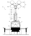
- FIG. 1 is a side view of the floodlight 1 according to the present embodiment
- FIG. 2 is a front view of the floodlight 1 according to the present embodiment
- the light projector 1 of the present embodiment is configured to include a telescopic strut 2, an elevating unit 26, dampers 27a and 27b, a lighting unit 3, a base 4, a cover 5, a pickup grip 6, and a power supply unit 7. It is sufficient that the light projector 1 according to the present invention includes at least the telescopic strut 2, the dampers 27a and 27b, the elevating unit 26, the lighting unit 3, and the base 4.
- the telescopic strut 2 is a device for raising and lowering the illuminating unit 3, and in the present embodiment is configured to include first to fifth struts 21 to 25.
- the outer diameters of the first to fifth columns 21 to 25 are sequentially reduced, and the first to fifth columns 21 to 25 are loosely fitted to each other.
- a lower end of the first pillar 21 located at the lowest position is fixed to the base 4. In FIG. 1, the lower end of the first support 21 is covered with the cover 5.
- the elevating unit 26 is a device for vertically extending and contracting the first to fifth columns in conjunction with each other.
- a handle that can be manually operated is provided on the side surface of the first support 21.
- the lighting unit 3 attached to the fifth support 25 is moved up and down with the expansion and contraction of the expandable support 2.
- the elevating mechanism of the elevating unit 26 is not limited to a portable device using a wire, and various mechanisms such as using a gear can be adopted.
- the elevating unit 26 may use not only manual operation using a handle but also driving means such as a motor and an engine.
- the dampers 27a and 27b are arranged on the left and right side surfaces of the telescopic strut 2. In the present embodiment, it is fixed so that the position below the side wall of the first support 21 and the position above the side wall of the second support 22 are connected.
- the dampers 27a and 27b have a cylinder and a piston that slides inside the cylinder.
- the dampers 27a and 27b exert a biasing force in the up-down direction, and have a function of preventing the lighting unit 3 from dropping even if an obstacle such as a break in the wire of the elevating unit 26 occurs.
- the telescopic struts 2 are arranged symmetrically with respect to the telescopic struts 2, the telescopic struts 2 can be smoothly expanded and contracted in a well-balanced manner.
- dampers 27a and 27b are provided outside, even if the dampers 27a and 27b are obstructed, they can be easily replaced. Further, since the surface condition of the piston can be easily visually recognized from the outside, it is possible to early find the above-mentioned scratches that cause gas leakage.
- the fifth support 25 is provided with an illumination section 3 for illuminating the surroundings.
- the illumination unit 3 of the present embodiment includes four lights 31a to 31d, a pedestal fixed to the fifth support 25, and a support 32 that supports the lights 31a to 31d.
- the LEDs are used for the lights 31a to 31d of the present embodiment, various light sources such as a metal halide lamp can be used in addition to the LEDs.
- the lights 31a to 31d of the present embodiment employ a directional light source for illuminating the front.
- an omnidirectional light source such as a balloon type illumination which is often used at present is used. It may be.
- the base 4 of the present embodiment is provided with two wheels to facilitate movement.
- the base 4 only needs to be a member that can fix and position the telescopic strut 2 and can perform positioning, and does not have to have wheels.
- the base 4 and the first support 21 are rotatably fixed, and by rotating the first support 21 with respect to the base 4, the direction in which the illumination unit 3 illuminates. Can be changed.
- a power supply unit 7 is provided above the base 4 and inside the cover 5.
- the power supply unit 7 is a means for supplying power to the lights 31a to 31d, and includes a power generating engine, an alternator, a fuel tank, a battery, and the like. Note that the power supply unit 7 is not limited to the form installed on the base 4 as in the present embodiment, but may be configured to be installed outside.
- a pickup grip 6 used for transporting the projector 1 is provided.
- the pickup grip 6 is firmly fixed to the base 4.
- the projector 1 can be suspended.
- the projector 1 of the present embodiment can be folded compactly during transportation or the like.
- FIG. 3A is a side view showing a standing state of the lighting unit 3
- FIG. 3B is a side view showing a housed state of the lighting unit 3.
- the support portion 32 is provided so as to be rotatable about a rotation shaft 33 a with respect to the pedestal 33.
- the lighting unit 3 is set in an upright state as shown in FIG. 3A, and when the projector 1 is carried or the like, the rotation shaft 33a is centered as shown in FIG. Then, the support portion 32 is rotated to be in the housed state.
- the height of the light projector 1 can be suppressed, and transportation and the like can be easily performed.
- the pickup grip 6 be configured such that when the illumination unit 3 is rotated, the vertically upper part thereof is opened, that is, the illumination unit 3 does not hinder the cable to be suspended. Further, since the lights 31a to 31d are heavy, when the standing state is changed from the standing state to the housed state, the position of the center of gravity of the projector 1 changes. Therefore, the position of the pickup grip 6 is preferably a position corresponding to the position of the center of gravity of the stored state. When hanging using the pickup grip 6 in the housed state, it becomes possible to hang the projector 1 in the parallel state.
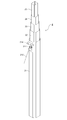
- FIG. 4 is a diagram showing a contracted state (FIG. 4A) and an extended state (FIG. 4B) of the telescopic strut 2 according to the embodiment of the present invention. 4 to 6, the illumination unit 3 located at the upper end of the fifth support 25 is illustrated as being removed.
- the first to fifth columns 21 to 25 are in the state of being accommodated in the respective interiors, and are in the shortest state.
- the lower end of the first support 21 is fixed to the base 4.
- the first column 21 is rotatable with respect to the base 4, and the direction of illumination by the illumination unit 3 can be changed.
- the telescopic strut 2 is extended upward.
- the telescopic strut 2 can be extended up to 7 m.
- the damper 27a includes a cylinder 271, a piston 272, and fixing portions 273a and 273b.
- two dampers 27a and 27b are used, and the other damper 27b is located on the opposite side of the first support 21 from the damper 27a.
- gas dampers are used for the dampers 27a and 27b, and the gas sealed in the dampers 27a and 27b can apply an urging force between the cylinder 271 and the piston 272.
- the fixing portion 273 a on the cylinder 271 side is fixed to the side wall of the second support 22.
- the fixed portion 273b on the piston 272 side is fixed to the side wall of the first support 21.
- the fixed portion 273a is fixed above the second support 22 and the fixed portion 273b is fixed below the first support 21 to maximize the amount of extension of the first support 21 and the second support 22. I have to do that.
- the first to fifth columns 21 to 25 are configured to expand and contract in conjunction with each other.
- the damper 27 a , 27b can prevent the lighting unit 3 from dropping sharply, and can prevent the lighting unit 3 from being damaged or the lighting unit 3 from colliding with a worker. It has become.
- the position of the illumination unit 3 when only the first support 21 and the second support 22 are extended be higher than the height of a general person (operator). Even if the third to fifth columns 23 to 25 drop due to a failure of the elevating unit 26, the illumination unit 3 may collide with the head of the worker or the like due to the urging force of the dampers 27a and 27b. It becomes possible to suppress.
- the lower part of the telescopic column 2 is located inside the cover 5.
- the lower side of the damper 27 a is located inside the cover 5, and it is possible to prevent foreign matter from adhering to the piston 272.
- a stretchable covering member such as a bellows shape around the piston 272.
- FIG. 5 is a perspective view of the telescopic strut 2 according to the embodiment of the present invention.
- the cross-sectional shape of the first to fifth columns 21 to 25 constituting the telescopic column 2 is an octagon in which four corners of the quadrilateral are chamfered by straight lines. With such a cross-sectional shape, the first to fifth columns 21 to 25 can smoothly expand and contract without rotating carelessly.
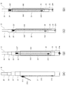
- FIG. 6 is a view for explaining the expansion and contraction operation of the telescopic strut 2 according to the embodiment of the present invention
- FIG. 7 is a cross-sectional view of the telescopic strut 2 according to the embodiment of the present invention.
- the extension mechanism of the extension column 2 will be described with reference to FIGS.
- the first to fifth columns 21 to 25 have an octagonal cross-sectional shape in which four corners of the quadrangular shape are chamfered.
- the second support 22 is loosely fitted inside the first support 21, but the first support 21 and the second support 22 are extended and contracted by being close to each other. It is composed of an operation restricting portion (in the vicinity of the upper, right, and lower portions in FIG.
- a pulley 211 is disposed in a space formed by the space forming portion formed by the first support 21 and the second support.
- a through hole 214 for disposing the pulley 211 is provided on the wall surface of the first support 21. This is for introducing the wire 212 from the outside into the space between the first support 21 and the second support 22.
- the pulley 211 is disposed in the through hole 214 such that the rotation surface is orthogonal to the wall surface of the first support 21.
- the wire 212 introduced from the outside is hung over the pulley 211 and then lowered vertically or substantially vertically downward to be fixed to the fixing portion 213 provided on the wall surface of the second support 22.
- FIG. 6A discloses the arrangement of the wires 212.
- the second column 22 rises with respect to the first column 21.
- the first support column 21 and the second support column 22 expand and contract along the rails by the above-described expansion and contraction restricting portion, and perform smooth expansion and contraction.
- the strut 22 can extend substantially vertically upward without being greatly bent and extended.
- the pulley 211 having a sufficient size can be arranged by the space forming portion capable of securing a space of a fixed size without the space being crushed by the sliding of the first support 21 and the second support 22. Becomes Therefore, it is possible to perform a smooth movement operation by the wire 212.
- the elevation of the third column 23 accompanying the elevation of the second column 22 will be described.
- the third column 23 is loosely fitted inside the second column 22, but the second column 22 and the third column 23 are similar to the case of the first column 21 and the second column 22.
- an operation restricting unit (right and lower, near the left side in FIG. 7) that regulates the expansion and contraction operation by being brought close to each other, and a space forming unit that forms a space where the pulley 221 and the like are separated from each other. (Near the upper part of FIG. 7).
- a pulley 221 is arranged in a space formed by the space forming part of the second support 22 and the third support 23.
- the pulley 221 is fixed to an inner wall of the second support 22, and a wire 222 connecting the first support 21 and the third support 23 is bridged.
- the rotation axis of the pulley 221 is provided perpendicularly (or substantially perpendicularly) to the wall surface of the second support 22. Therefore, the rotation surface of the pulley 221 is arranged along the wall surface of the second support 22, and the pulley 221 having a sufficient size can be disposed without necessity of making the second support 22 inadvertently thick. Is possible.
- the wire 222 bridged over the pulley 221 has one end fixed to a fixing portion 224 provided below the first column 21 and the other end fixed to a side surface of the third column 23. 223.
- the wire 222 is disposed so as to descend substantially perpendicularly from the pulley 221 to the fixed part 223 or the fixed part 224. Such an arrangement of the wire 222 enables the wire 222 and the pulley 221 to move smoothly.
- the wire 222 and the pulley 221 are arranged in a space (a space formed by the space forming part) that is not hindered by expansion and contraction of the second support 22 and the third support 23, This makes it possible to smoothly expand and contract the third support column 23, and to prevent the pulley 221 and the like from breaking down due to repeated sliding, or to suppress problems such as the wire 222 being cut due to repeated sliding.
- the second support column 22 is raised by pulling the wire 212 from the outside.
- the pulley 221 provided on the second support 22 rises as the second support 22 rises, and the wire 222 bridged over the pulley 221 becomes the third pulley.
- the fixing portion 223 fixed to the column 23 rises.
- the lifting and lowering of the fourth column 24 accompanying the lifting and lowering of the third column 23 will be described.
- the fourth column 24 is loosely fitted inside the third column 23, but the third column 23 and the fourth column are similar to the case of the first column 21 and the second column 22.
- an operation restricting unit in the lower, left, and right vicinity in FIG. 7 that restricts the expansion and contraction operation by being brought close to each other, and a space forming unit that forms a space in which the pulley 231 and the like are separated from each other. (Near the right side of FIG. 7).
- a pulley 231 is disposed in a space formed by the space forming portion formed by the third support 23 and the fourth support 24.
- the pulley 231 is fixed to the inner wall of the third support 23, and a wire 232 connecting the second support 22 and the fourth support 24 is bridged.
- the rotation axis of the pulley 231 is provided perpendicularly (or substantially perpendicularly) to the wall surface of the third support column 23. Therefore, the rotation surface of the pulley 231 is disposed along the wall surface of the third support 23, and the pulley 231 having a sufficient size can be disposed without necessitating the third support 23 to be inadvertently thickened. Is possible.
- the wire 232 bridged over the pulley 231 has one end fixed to a fixing portion 234 provided below the second support 22, and the other end fixed to a side surface of the fourth support 24. 233.
- the wire 232 is disposed so as to descend substantially perpendicularly from the pulley 231 to the fixed portion 233 or the fixed portion 234.
- the third column 23 rises in conjunction with the pulling of the wire 212.
- the pulley 231 provided on the third support 23 rises in accordance with the rise of the third support 23, and the wire 232 bridged over the pulley 231 is connected to the fourth support 23.
- the fourth column 24 rises.
- the fourth support 24 is loosely fitted inside the fifth support 25, but the fourth support 24 and the fifth support 25 are similar to the case of the first support 21 and the second support 22.
- an operation restricting unit in the vicinity of the left, upper, and right sides in FIG. 7 that restricts the expansion and contraction operation by being close to each other, and a space forming unit that forms a space separated from each other and provided with a pulley 241 and the like. (Near the lower part of FIG. 7).
- a pulley 241 is arranged in a space formed by the space forming part of the fourth support 24 and the fifth support 25.
- the pulley 241 is fixed to the inner wall of the fourth support 24, and a wire 242 connecting the third support 23 and the fifth support 25 is bridged.
- the rotation axis of the pulley 241 is provided perpendicularly (or substantially perpendicularly) to the wall surface of the fourth support 24. Therefore, the rotating surface of the pulley 241 is disposed along the wall surface of the fourth support 24, and the pulley 241 having a sufficient size can be disposed without necessitating the fourth support 24 to be inadvertently thickened. Is possible.
- the wire 242 bridged over the pulley 241 has one end fixed to a fixing portion 244 provided below the third support 23 and the other end fixed to a side surface of the fifth support 25. 243.
- the wire 242 is disposed so as to descend substantially perpendicularly from the pulley 241 to the fixed portion 243 or the fixed portion 244.
- the fourth column 24 rises in conjunction with the pulling of the wire 212.
- the pulley 241 provided on the fourth support 24 rises in accordance with the rise of the fourth support 24, and the wire 242 bridged over the pulley 241 becomes the fifth pulley 241.
- the fifth column 25 rises.
- the wire 212 exposed to the outside of the telescopic strut 2 is wound by the drum provided on the elevating unit 26,
- the second support 22 rises.
- the third support 23, the fourth support 24, and the fifth support 25 move upward in conjunction with each other.
- the operation restricting portion between the adjacent first to fifth columns 21 to 25, such as the first column 21 and the second column 22 the sliding of the columns is smooth and It is possible to move vertically (or almost vertically).
- the pulleys 211, 221, 231, and 241 are arranged in a space that is not hindered by sliding of the first to fifth columns 21 to 25, so that a smooth lifting operation can be performed.
- the spatial positions formed by the space forming portions are arranged at different positions on the cross-sectional circumference of the telescopic strut 2 (the space formed by the first struts 21 and the second struts 22). Is the left side of FIG. 7, the space formed by the second support 22 and the third support 23 is above FIG. 7, and the space formed by the third support 23 and the fourth support 24 is 7 and the space formed by the fourth support 24 and the fifth support 25 is below FIG. 7), so that the telescopic support 2 is not unnecessarily thickened, and 2 can be expanded and contracted in a well-balanced manner.
- the expansion and contraction mechanism of the telescopic strut 2 used in the floodlight 1 of the present embodiment has been described.
- the sliding can be performed smoothly and vertically (or substantially vertically), and the sliding portion is formed by the space forming portion.
- the operations of these members are operated without being hindered by expansion and contraction, and smooth expansion and contraction And it is possible to suppress a failure of a member that performs expansion and contraction operations, such as a pulley and a wire.
- the dampers 27a and 27b are provided between the first support 21 and the second support 22, so that the vertical direction of the second support 22 with respect to the first support 21 is regulated in an appropriate direction. 2 makes the lifting and lowering smoother.
- each of the first to fifth columns 21 to 25 uses an octagonal cross-sectional shape in which four corners of a quadrangular shape are chamfered.
- the cross-sectional shape is not limited to such a shape, and may be a polygon having five or more pentagons. Alternatively, it may be configured in a shape having a curved surface.
- the telescopic strut 2 that raises and lowers the illumination unit 3 in the floodlight 1 has been described. It can also be an object.
Abstract
Le problème décrit par la présente invention est de monter et descendre en douceur une perche télescopique utilisée avec un projecteur. À cet effet, le projecteur selon la présente invention comprend : une perche télescopique (2), qui comprend une pluralité de perches (21) - (25) ayant des diamètres externes qui diminuent progressivement, les perches (21) - (25) étant emboîtées les unes dans les autres de manière à permettre un jeu entre elles et pouvant se télescoper dans la direction verticale ; un éclairage (3) monté sur la perche la plus centrale (25) ; une partie d'élévation-abaissement (26) qui amène les perches (21) - (25) à fonctionner en tandem de manière à se télescoper dans la direction verticale ; une base (4) à laquelle la perche la plus à l'extérieur est fixée ; et des clapets (27a), (27b) qui relient une surface latérale de la perche la plus à l'extérieur (21) et une surface latérale de la seconde perche la plus à l'extérieur (22).
Priority Applications (2)
| Application Number | Priority Date | Filing Date | Title |
|---|---|---|---|
| US17/269,882 US11402086B2 (en) | 2018-08-24 | 2019-07-31 | Floodlight |
| EP19851044.8A EP3842690A4 (fr) | 2018-08-24 | 2019-07-31 | Projecteur |
Applications Claiming Priority (2)
| Application Number | Priority Date | Filing Date | Title |
|---|---|---|---|
| JP2018-156931 | 2018-08-24 | ||
| JP2018156931A JP6906797B2 (ja) | 2018-08-24 | 2018-08-24 | 投光器 |
Publications (1)
| Publication Number | Publication Date |
|---|---|
| WO2020039870A1 true WO2020039870A1 (fr) | 2020-02-27 |
Family
ID=69592994
Family Applications (1)
| Application Number | Title | Priority Date | Filing Date |
|---|---|---|---|
| PCT/JP2019/030087 WO2020039870A1 (fr) | 2018-08-24 | 2019-07-31 | Projecteur |
Country Status (4)
| Country | Link |
|---|---|
| US (1) | US11402086B2 (fr) |
| EP (1) | EP3842690A4 (fr) |
| JP (1) | JP6906797B2 (fr) |
| WO (1) | WO2020039870A1 (fr) |
Cited By (2)
| Publication number | Priority date | Publication date | Assignee | Title |
|---|---|---|---|---|
| JP2021173391A (ja) * | 2020-04-30 | 2021-11-01 | トヨタ自動車株式会社 | 伸縮機構及び移動体 |
| JP2021173392A (ja) * | 2020-04-30 | 2021-11-01 | トヨタ自動車株式会社 | 伸縮機構及び移動体 |
Families Citing this family (3)
| Publication number | Priority date | Publication date | Assignee | Title |
|---|---|---|---|---|
| KR102195316B1 (ko) * | 2020-11-02 | 2020-12-24 | 이범섭 | 레일을 따라 슬라이딩 이동 가능한 조명을 구비한 조명 기구 |
| CN113654011B (zh) * | 2021-08-13 | 2023-06-16 | 安徽艳阳电气集团有限公司 | 一种船舶用便于拆装的灯架 |
| KR102548493B1 (ko) * | 2022-12-27 | 2023-06-28 | 신창엔텍 주식회사 | 높이조절이 가능한 안전등조립체 |
Citations (2)
| Publication number | Priority date | Publication date | Assignee | Title |
|---|---|---|---|---|
| JP2000082306A (ja) * | 1998-09-04 | 2000-03-21 | Nikken Corp | 照明装置 |
| WO2005068901A1 (fr) * | 2004-01-15 | 2005-07-28 | Light Boy Co., Ltd. | Projecteur |
Family Cites Families (9)
| Publication number | Priority date | Publication date | Assignee | Title |
|---|---|---|---|---|
| JP3197834B2 (ja) * | 1996-12-06 | 2001-08-13 | 株式会社グリーン・サービス | 投光機 |
| US6276811B1 (en) * | 1998-04-30 | 2001-08-21 | Green Service Co., Ltd. | Projector and its telescopic post |
| US6237904B1 (en) * | 1999-02-10 | 2001-05-29 | John D. Shepherd | Motion stabilizer |
| JP2002358818A (ja) * | 2001-06-01 | 2002-12-13 | Sanyo Kiki Co Ltd | 電気器具の昇降装置 |
| US7988343B2 (en) * | 2007-04-26 | 2011-08-02 | Palmisano Jr Lester J | Easy-glide offshore ready light tower system |
| CN102224376B (zh) * | 2009-12-11 | 2013-03-27 | 萧绍端 | 移动式灯塔 |
| CN103363380B (zh) * | 2012-03-28 | 2016-09-28 | 海洋王照明科技股份有限公司 | 移动式灯塔 |
| US10618580B2 (en) * | 2014-06-06 | 2020-04-14 | Gino Kennedy | Stackable horizontal mast assembly |
| US9598875B1 (en) * | 2016-01-28 | 2017-03-21 | Multiquip, Inc. | Telescoping mast assembly with safety latch system |
-
2018
- 2018-08-24 JP JP2018156931A patent/JP6906797B2/ja active Active
-
2019
- 2019-07-31 US US17/269,882 patent/US11402086B2/en active Active
- 2019-07-31 EP EP19851044.8A patent/EP3842690A4/fr active Pending
- 2019-07-31 WO PCT/JP2019/030087 patent/WO2020039870A1/fr unknown
Patent Citations (3)
| Publication number | Priority date | Publication date | Assignee | Title |
|---|---|---|---|---|
| JP2000082306A (ja) * | 1998-09-04 | 2000-03-21 | Nikken Corp | 照明装置 |
| WO2005068901A1 (fr) * | 2004-01-15 | 2005-07-28 | Light Boy Co., Ltd. | Projecteur |
| JP2005203237A (ja) | 2004-01-15 | 2005-07-28 | Light Boy Co Ltd | 投光機 |
Non-Patent Citations (1)
| Title |
|---|
| See also references of EP3842690A4 |
Cited By (4)
| Publication number | Priority date | Publication date | Assignee | Title |
|---|---|---|---|---|
| JP2021173391A (ja) * | 2020-04-30 | 2021-11-01 | トヨタ自動車株式会社 | 伸縮機構及び移動体 |
| JP2021173392A (ja) * | 2020-04-30 | 2021-11-01 | トヨタ自動車株式会社 | 伸縮機構及び移動体 |
| JP7276241B2 (ja) | 2020-04-30 | 2023-05-18 | トヨタ自動車株式会社 | 伸縮機構及び移動体 |
| JP7314857B2 (ja) | 2020-04-30 | 2023-07-26 | トヨタ自動車株式会社 | 伸縮機構及び移動体 |
Also Published As
| Publication number | Publication date |
|---|---|
| US20210317973A1 (en) | 2021-10-14 |
| EP3842690A1 (fr) | 2021-06-30 |
| EP3842690A4 (fr) | 2022-04-06 |
| JP6906797B2 (ja) | 2021-07-21 |
| JP2020031000A (ja) | 2020-02-27 |
| US11402086B2 (en) | 2022-08-02 |
Similar Documents
| Publication | Publication Date | Title |
|---|---|---|
| WO2020039870A1 (fr) | Projecteur | |
| JP4432108B2 (ja) | 投光機 | |
| KR101716094B1 (ko) | 국기 게양대 | |
| JP2005082352A (ja) | タワークレーン | |
| JP2009020111A (ja) | 原子炉整備用プラットホーム | |
| JP2020152491A (ja) | 伸縮ブーム用の伸縮シリンダアセンブリ | |
| JP4536560B2 (ja) | ポール灯 | |
| KR102428674B1 (ko) | 길이 조절 가능한 가로등 장치 | |
| JP2000195328A (ja) | 投光機及びその伸縮支柱 | |
| JP6887221B2 (ja) | エレベーター用足場台 | |
| JP2019206817A (ja) | 鉄塔支持型煙突の解体方法および鉄塔支持型煙突の解体装置 | |
| JP4929656B2 (ja) | マンコンベア用制御装置の持ち出し装置 | |
| KR20120051230A (ko) | 이동식 조명장치 | |
| JP6632591B2 (ja) | クレーン | |
| CN207584597U (zh) | 一种建筑施工工地的辅助照明装置 | |
| JPH08138421A (ja) | 屋外用昇降式照明器具 | |
| JPH11317109A (ja) | 投光機及びその伸縮支柱 | |
| JP2000264588A (ja) | 伸縮マスト | |
| JP3189159U (ja) | 投光機 | |
| JP2018142526A (ja) | 投光器 | |
| JP2510293Y2 (ja) | 建設工事用照明スタンド | |
| CN202195446U (zh) | 一种用于天车照明的灯具吊架 | |
| JP2010129208A (ja) | ポール型照明器具 | |
| KR20170010654A (ko) | 확장형 연등 리프팅 장치 | |
| JPH0726870A (ja) | ボーリング用マスト装置 |
Legal Events
| Date | Code | Title | Description |
|---|---|---|---|
| 121 | Ep: the epo has been informed by wipo that ep was designated in this application |
Ref document number: 19851044 Country of ref document: EP Kind code of ref document: A1 |
|
| NENP | Non-entry into the national phase |
Ref country code: DE |
|
| ENP | Entry into the national phase |
Ref document number: 2019851044 Country of ref document: EP Effective date: 20210324 |