WO2019123699A1 - Dispositif de support d'outil et machine-outil - Google Patents
Dispositif de support d'outil et machine-outil Download PDFInfo
- Publication number
- WO2019123699A1 WO2019123699A1 PCT/JP2018/025753 JP2018025753W WO2019123699A1 WO 2019123699 A1 WO2019123699 A1 WO 2019123699A1 JP 2018025753 W JP2018025753 W JP 2018025753W WO 2019123699 A1 WO2019123699 A1 WO 2019123699A1
- Authority
- WO
- WIPO (PCT)
- Prior art keywords
- tool
- shaft
- bearing
- tool holding
- disposed
- Prior art date
Links
- 230000005540 biological transmission Effects 0.000 claims abstract description 5
- 238000012423 maintenance Methods 0.000 description 7
- 238000000034 method Methods 0.000 description 5
- 230000000149 penetrating effect Effects 0.000 description 2
- 230000000694 effects Effects 0.000 description 1
- 238000003754 machining Methods 0.000 description 1
Images


Classifications
-
- B—PERFORMING OPERATIONS; TRANSPORTING
- B23—MACHINE TOOLS; METAL-WORKING NOT OTHERWISE PROVIDED FOR
- B23Q—DETAILS, COMPONENTS, OR ACCESSORIES FOR MACHINE TOOLS, e.g. ARRANGEMENTS FOR COPYING OR CONTROLLING; MACHINE TOOLS IN GENERAL CHARACTERISED BY THE CONSTRUCTION OF PARTICULAR DETAILS OR COMPONENTS; COMBINATIONS OR ASSOCIATIONS OF METAL-WORKING MACHINES, NOT DIRECTED TO A PARTICULAR RESULT
- B23Q3/00—Devices holding, supporting, or positioning work or tools, of a kind normally removable from the machine
- B23Q3/155—Arrangements for automatic insertion or removal of tools, e.g. combined with manual handling
- B23Q3/1552—Arrangements for automatic insertion or removal of tools, e.g. combined with manual handling parts of devices for automatically inserting or removing tools
- B23Q3/15526—Storage devices; Drive mechanisms therefor
- B23Q3/15536—Non-rotary fixed racks
-
- B—PERFORMING OPERATIONS; TRANSPORTING
- B23—MACHINE TOOLS; METAL-WORKING NOT OTHERWISE PROVIDED FOR
- B23Q—DETAILS, COMPONENTS, OR ACCESSORIES FOR MACHINE TOOLS, e.g. ARRANGEMENTS FOR COPYING OR CONTROLLING; MACHINE TOOLS IN GENERAL CHARACTERISED BY THE CONSTRUCTION OF PARTICULAR DETAILS OR COMPONENTS; COMBINATIONS OR ASSOCIATIONS OF METAL-WORKING MACHINES, NOT DIRECTED TO A PARTICULAR RESULT
- B23Q1/00—Members which are comprised in the general build-up of a form of machine, particularly relatively large fixed members
- B23Q1/70—Stationary or movable members for carrying working-spindles for attachment of tools or work
-
- B—PERFORMING OPERATIONS; TRANSPORTING
- B23—MACHINE TOOLS; METAL-WORKING NOT OTHERWISE PROVIDED FOR
- B23B—TURNING; BORING
- B23B25/00—Accessories or auxiliary equipment for turning-machines
- B23B25/06—Measuring, gauging, or adjusting equipment on turning-machines for setting-on, feeding, controlling, or monitoring the cutting tools or work
-
- B—PERFORMING OPERATIONS; TRANSPORTING
- B23—MACHINE TOOLS; METAL-WORKING NOT OTHERWISE PROVIDED FOR
- B23B—TURNING; BORING
- B23B29/00—Holders for non-rotary cutting tools; Boring bars or boring heads; Accessories for tool holders
- B23B29/24—Tool holders for a plurality of cutting tools, e.g. turrets
- B23B29/244—Toolposts, i.e. clamping quick-change toolholders, without description of the angular positioning device
- B23B29/246—Quick-change tool holders
-
- B—PERFORMING OPERATIONS; TRANSPORTING
- B23—MACHINE TOOLS; METAL-WORKING NOT OTHERWISE PROVIDED FOR
- B23B—TURNING; BORING
- B23B3/00—General-purpose turning-machines or devices, e.g. centre lathes with feed rod and lead screw; Sets of turning-machines
- B23B3/06—Turning-machines or devices characterised only by the special arrangement of constructional units
- B23B3/065—Arrangements for performing other machining operations, e.g. milling, drilling
-
- B—PERFORMING OPERATIONS; TRANSPORTING
- B23—MACHINE TOOLS; METAL-WORKING NOT OTHERWISE PROVIDED FOR
- B23B—TURNING; BORING
- B23B39/00—General-purpose boring or drilling machines or devices; Sets of boring and/or drilling machines
- B23B39/16—Drilling machines with a plurality of working-spindles; Drilling automatons
- B23B39/161—Drilling machines with a plurality of working-spindles; Drilling automatons with parallel work spindles
- B23B39/167—Drilling machines with a plurality of working-spindles; Drilling automatons with parallel work spindles having belt and chain transmissions
-
- B—PERFORMING OPERATIONS; TRANSPORTING
- B23—MACHINE TOOLS; METAL-WORKING NOT OTHERWISE PROVIDED FOR
- B23C—MILLING
- B23C1/00—Milling machines not designed for particular work or special operations
- B23C1/04—Milling machines not designed for particular work or special operations with a plurality of horizontal working-spindles
-
- B—PERFORMING OPERATIONS; TRANSPORTING
- B23—MACHINE TOOLS; METAL-WORKING NOT OTHERWISE PROVIDED FOR
- B23Q—DETAILS, COMPONENTS, OR ACCESSORIES FOR MACHINE TOOLS, e.g. ARRANGEMENTS FOR COPYING OR CONTROLLING; MACHINE TOOLS IN GENERAL CHARACTERISED BY THE CONSTRUCTION OF PARTICULAR DETAILS OR COMPONENTS; COMBINATIONS OR ASSOCIATIONS OF METAL-WORKING MACHINES, NOT DIRECTED TO A PARTICULAR RESULT
- B23Q3/00—Devices holding, supporting, or positioning work or tools, of a kind normally removable from the machine
- B23Q3/12—Devices holding, supporting, or positioning work or tools, of a kind normally removable from the machine for securing to a spindle in general
-
- B—PERFORMING OPERATIONS; TRANSPORTING
- B23—MACHINE TOOLS; METAL-WORKING NOT OTHERWISE PROVIDED FOR
- B23Q—DETAILS, COMPONENTS, OR ACCESSORIES FOR MACHINE TOOLS, e.g. ARRANGEMENTS FOR COPYING OR CONTROLLING; MACHINE TOOLS IN GENERAL CHARACTERISED BY THE CONSTRUCTION OF PARTICULAR DETAILS OR COMPONENTS; COMBINATIONS OR ASSOCIATIONS OF METAL-WORKING MACHINES, NOT DIRECTED TO A PARTICULAR RESULT
- B23Q39/00—Metal-working machines incorporating a plurality of sub-assemblies, each capable of performing a metal-working operation
- B23Q39/02—Metal-working machines incorporating a plurality of sub-assemblies, each capable of performing a metal-working operation the sub-assemblies being capable of being brought to act at a single operating station
- B23Q39/021—Metal-working machines incorporating a plurality of sub-assemblies, each capable of performing a metal-working operation the sub-assemblies being capable of being brought to act at a single operating station with a plurality of toolheads per workholder, whereby the toolhead is a main spindle, a multispindle, a revolver or the like
- B23Q39/022—Metal-working machines incorporating a plurality of sub-assemblies, each capable of performing a metal-working operation the sub-assemblies being capable of being brought to act at a single operating station with a plurality of toolheads per workholder, whereby the toolhead is a main spindle, a multispindle, a revolver or the like with same working direction of toolheads on same workholder
- B23Q39/024—Metal-working machines incorporating a plurality of sub-assemblies, each capable of performing a metal-working operation the sub-assemblies being capable of being brought to act at a single operating station with a plurality of toolheads per workholder, whereby the toolhead is a main spindle, a multispindle, a revolver or the like with same working direction of toolheads on same workholder consecutive working of toolheads
-
- B—PERFORMING OPERATIONS; TRANSPORTING
- B23—MACHINE TOOLS; METAL-WORKING NOT OTHERWISE PROVIDED FOR
- B23Q—DETAILS, COMPONENTS, OR ACCESSORIES FOR MACHINE TOOLS, e.g. ARRANGEMENTS FOR COPYING OR CONTROLLING; MACHINE TOOLS IN GENERAL CHARACTERISED BY THE CONSTRUCTION OF PARTICULAR DETAILS OR COMPONENTS; COMBINATIONS OR ASSOCIATIONS OF METAL-WORKING MACHINES, NOT DIRECTED TO A PARTICULAR RESULT
- B23Q39/00—Metal-working machines incorporating a plurality of sub-assemblies, each capable of performing a metal-working operation
- B23Q2039/006—Machines with multi-spindles
-
- B—PERFORMING OPERATIONS; TRANSPORTING
- B23—MACHINE TOOLS; METAL-WORKING NOT OTHERWISE PROVIDED FOR
- B23Q—DETAILS, COMPONENTS, OR ACCESSORIES FOR MACHINE TOOLS, e.g. ARRANGEMENTS FOR COPYING OR CONTROLLING; MACHINE TOOLS IN GENERAL CHARACTERISED BY THE CONSTRUCTION OF PARTICULAR DETAILS OR COMPONENTS; COMBINATIONS OR ASSOCIATIONS OF METAL-WORKING MACHINES, NOT DIRECTED TO A PARTICULAR RESULT
- B23Q5/00—Driving or feeding mechanisms; Control arrangements therefor
- B23Q5/02—Driving main working members
- B23Q5/04—Driving main working members rotary shafts, e.g. working-spindles
- B23Q5/10—Driving main working members rotary shafts, e.g. working-spindles driven essentially by electrical means
-
- Y—GENERAL TAGGING OF NEW TECHNOLOGICAL DEVELOPMENTS; GENERAL TAGGING OF CROSS-SECTIONAL TECHNOLOGIES SPANNING OVER SEVERAL SECTIONS OF THE IPC; TECHNICAL SUBJECTS COVERED BY FORMER USPC CROSS-REFERENCE ART COLLECTIONS [XRACs] AND DIGESTS
- Y10—TECHNICAL SUBJECTS COVERED BY FORMER USPC
- Y10T—TECHNICAL SUBJECTS COVERED BY FORMER US CLASSIFICATION
- Y10T29/00—Metal working
- Y10T29/51—Plural diverse manufacturing apparatus including means for metal shaping or assembling
- Y10T29/5104—Type of machine
- Y10T29/5109—Lathe
- Y10T29/5114—Lathe and tool
-
- Y—GENERAL TAGGING OF NEW TECHNOLOGICAL DEVELOPMENTS; GENERAL TAGGING OF CROSS-SECTIONAL TECHNOLOGIES SPANNING OVER SEVERAL SECTIONS OF THE IPC; TECHNICAL SUBJECTS COVERED BY FORMER USPC CROSS-REFERENCE ART COLLECTIONS [XRACs] AND DIGESTS
- Y10—TECHNICAL SUBJECTS COVERED BY FORMER USPC
- Y10T—TECHNICAL SUBJECTS COVERED BY FORMER US CLASSIFICATION
- Y10T408/00—Cutting by use of rotating axially moving tool
- Y10T408/36—Machine including plural tools
- Y10T408/385—Rotatable about parallel axes
Definitions
- the present invention relates to a tool holding device for holding a tool, and a machine tool having such a tool holding device.
- an object of this invention is to provide the tool holding
- the tool holding device rotatably holds a first axis having a first tool holding portion disposed at one end, a second axis having a second tool holding portion disposed at one end, and the first axis.
- a driving force input unit that rotates the first axis in response to the input driving force, and a rotation transmission that rotates the second axis in response to the rotation of the first axis. It is preferable to further have a part.
- the length of the first protrusion is preferably longer than the length of the second protrusion.
- the machine tool according to the embodiment is engaged with the tool holding base having the driving force output unit that outputs the driving force, the first recess and the second recess, and the tool holding base, and is disposed in the same direction.
- a tool holding device for holding a plurality of rotary tools the tool holding device projecting from a first surface, a second surface opposite the first surface, and a direction opposite to the first surface from the second surface
- a plurality of rotary tools arranged in the same direction can be held easily and stably.
- FIG. 1 It is a figure (the 1) which shows a prior art. It is a figure (the 2) which shows a prior art. It is a perspective view of a machine tool concerning an embodiment.
- A) is a fragmentary perspective view of the back surface tool stand in the state where the back surface tool holding device shown in FIG. 3 is not mounted,
- (b) is the back surface tool base in the state where the back surface tool holding device shown in FIG. FIG.
- (A) is a top view of the back tool holding device shown in FIG. 5
- (b) is a front view of the back tool holding device shown in FIG. 5
- (c) is a side view of the back tool holding device shown in FIG. FIG. FIG.
- FIG. 5 is a cross-sectional view taken along the line AA 'of FIG. 4 (b).
- FIG. 6 is a view showing an engagement method of engaging the back tool holding device shown in FIG. 5 with the back tool stand shown in FIG. 3; It is a figure which shows the rotation mechanism which rotates the 1st axis
- FIG. 14 is a cross-sectional view taken along the line AA ′ of FIG
- the tool holding device extends in parallel to the first axis, which rotates in response to the driving force input to the driving force input unit, and rotates the first tool holding unit, and the first axis.
- a second shaft that rotates in response to the rotation of the second tool holder to rotate the second tool holder, and a housing that accommodates the first shaft and the second shaft.
- One end of the second shaft is accommodated in a second convex portion that protrudes from the second surface of the housing.
- the length of the second axis corresponds to the length of the second projection. The length can be increased.
- the length of the second axis is increased by the length corresponding to the length of the second convex portion, so the rotational position of the second axis is stabilized, and the other end of the second axis It is possible to improve the machining accuracy of the workpiece to be machined by the tool held by the second tool holder arranged in
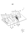
- FIG. 3 is a schematic perspective view of the machine tool according to the embodiment.
- the machine tool 1 has a front main spindle 10, a front tool holder 20, a back main spindle 30, and a back tool holder 40.
- the front spindle unit 10, the front tool holding unit 20, the back spindle unit 30, and the back tool holding unit 40 are mounted on a flat base 100.
- the front main spindle unit 10 includes a front main spindle 11, a front main spindle 12, a guide bush support 13, a guide bush 14, and a main spindle Z-axis rail 15, and rotatably holds the first workpiece W1.
- the front spindle mount 11 is slidably supported by a main spindle Z-axis rail 15 extending in a direction parallel to the Z direction (hereinafter also referred to as an axial direction) in which the main spindle extends.
- the position of the headstock 11 in the Z direction is controlled by a numerical control (NC) device (not shown).
- the front main spindle 12 is a shaft member extending in the Z direction, and holds the first work W1 at one end.
- the front main spindle 12 is rotatably mounted on the front spindle stock 11.
- the front main spindle 12 moves in the Z direction in response to the movement of the front headstock 11 in the Z direction.
- the guide bush support 13 is disposed between the front spindle stock 11 and the front tool holder 20 and supports the guide bush 14.
- the guide bush 14 is supported by the guide bush support 13, and rotatably and slidably holds and guides the first workpiece W1 which moves in the Z-axis direction together with the front main shaft 12 at the time of processing to prevent vibration.
- the spindle Z-axis rail 15 supports the front spindle head 11 slidably in the Z direction.
- the front tool holding unit 20 includes a front tool stand 21, a front tool holding device 22, a front tool 23, a tool X axis rail 24, a tool X axis slide table 25, a tool Z axis rail 26, and a tool Z axis.
- a slide table 27 and a tool Y axis rail 28 are provided.
- the positions of the front tool stand 21 in the X direction, Y direction, and Z direction are controlled by an NC device (not shown).
- the front tool holding device 22 is supported by the front tool stand 21 and holds the front tool 23.
- the front tool 23 is a tool that performs various processes on the first workpiece W1.
- the tool X axis rail 24 slidably supports the tool X axis slide table 25 in the X direction.
- the tool X-axis slide table 25 supports the tool Z-axis rail 26.
- the tool Z-axis rail 26 slidably supports the tool Z-axis slide table 27 in the Z direction.
- the tool Z-axis slide table 27 supports the tool Y-axis rail 28.
- the tool Y-axis rail 28 slidably supports the front tool stand 21 in the Y direction.
- the front tool holder 21 is slidably supported in the X direction, the Y direction and the Z direction by the tool X axis rail 24, the tool Z axis rail 26 and the tool Y axis rail 28.
- the back spindle 30 has a back spindle 31 and a back spindle 32, and rotatably holds the second workpiece W2.
- the back headstock 31 is integrated with the front tool rest 21 and is slidably supported in the X direction, the Y direction and the Z direction by the tool X axis rail 24, the tool Z axis rail 26 and the tool Y axis rail 28.
- the rear main shaft 32 is an axial member extending in the Z direction, that is, the axial direction, and holds the second workpiece W2 at one end.
- the back spindle 32 is rotatably mounted on the back spindle 31. The back spindle 32 moves in the X, Y, and Z directions in response to the back spindle 31 moving in the X, Y, and Z directions.
- the back tool holder 40 has a back tool stand 50, a back tool holder 60, and a back tool 70.
- the back tool stand 50 is fixed to the base 100.
- the back tool holding device 60 is supported by the back tool stand 50 and holds the back tool 70.
- the back surface tool 70 is a rotary tool that performs various processes on the second workpiece W2.
- FIG. 4 (a) is a partial perspective view of the back tool stand 50 in a state in which the back tool holding device 60 is not attached
- FIG. 4 (b) is a back tool stand 50 in a state in which the back tool holding device 60 is attached.
- the back tool stand 50 has a base 51 and a plate 52.
- the base 51 is fixed to the base 100, and the plate 52 is fixed to the base 51 by a fastening member 53 such as a screw.
- a fastening member 53 such as a screw.
- the plate member 52 four through holes 54 and four non-through holes 55 are formed.
- Each of the four through holes 54 is a cylindrical hole penetrating from one surface of the plate 52 to the other surface.
- a recess 56 is formed on the surface of the base 51 corresponding to the through hole 54.
- the four non-through holes 55 are cylindrical recesses having a circular bottom surface 57.
- FIG. 5 is a perspective view of the back tool holding device 60
- FIG. 6 (a) is a plan view
- FIG. 6 (b) is a front view
- FIG. 6 (c) is a side view
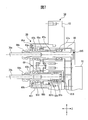
- FIG. 7 is a cross-sectional view taken along the line AA 'of FIG. 4 (b).
- the back surface tool holding device 60 includes a housing 61, a first shaft 62a, a second shaft 62b, a first tool holding portion 63a, a second tool holding portion 63b, a first tightening member 64a, and a second A clamping member 64 b, a first lid member 65 a, a second lid member 65 b, and a driving force input unit 66 are provided.
- the back surface tool holding device 60 further includes a first convex portion 615 and a second convex portion 616.
- the housing 61 has a first body 611 and a second body 612.
- the first body portion 611 is a hollow member having a first surface 613, through which the first shaft 62a and the second shaft 62b pass.
- the second body portion 612 is a hollow member having a second surface 614 opposite to the first surface, and the first convex portion 615 and the first convex portion 615 in a direction opposite to the first surface 613 from the second surface 614.
- the 2 convex part 616 protrudes.
- the first body portion 611 and the second body portion 612 are fastened by a first fastening member 617 a and a second fastening member 617 b.
- the first shaft 62 a is a rod-like member extending in the Z direction, that is, in the axial direction, which is disposed to penetrate the body between the first surface 613 and the second surface 614 of the housing 61.
- the first tool holding portion 63a is disposed, the other end is accommodated in the first convex portion 615, and the driving force input portion 66 is disposed.
- the second shaft 62 b is an axially extending rod-like member disposed so as to penetrate the inside of the housing 61, the second tool holding portion 63 b is disposed at one end, and the other end is a second convex portion 616. Housed in
- the first tool holder 63a holds the first rotary tool 70a by holding the end of the first rotary tool 70a.
- the second tool holder 63b holds the second rotary tool 70b by holding the end of the second rotary tool 70b.
- the first lid member 65a is disposed between the first body portion 611 and the first tool holding portion 63a, and covers a hole through which the first shaft 62a passes.
- the second lid member 65b is disposed between the first body portion 611 and the second tool holding portion 63b and covers a hole through which the second shaft 62b passes.
- the first tightening member 64a fixes the first rotary tool 70a held by the first tool holding portion 63a by means of a chuck mechanism which is screwed and tightened in a screw groove formed in the first tool holding portion 63a.
- the second tightening member 64b fixes the second rotary tool 70b held by the second tool holding portion 63b by means of a chuck mechanism which is screwed and tightened in a screw groove formed in the second tool holding portion 63b.
- the back tool holding device 60 further includes a first bearing 67a, a second bearing 67b, a third bearing 67c, a fourth bearing 67d, a first gear portion 68a, and a second gear portion 68b, and is driven.
- the driving force transmitting member 80 is wound.
- the first bearing 67a is accommodated in the first convex portion 615 and rotatably holds the first shaft 62a.
- the second bearing 67 b is disposed between the first tool holding portion 63 a and the first bearing 67 a and rotatably holds the first shaft 62 a.
- the third bearing 67 c is accommodated in the second protrusion 616 and rotatably holds the second shaft 62 b.
- the fourth bearing 67 d is disposed between the second tool holding portion 63 b and the third bearing 67 c and rotatably holds the second shaft 62 b.
- the first gear portion 68a is a gear disposed around the circumference of the first shaft 62a
- the second gear portion 68b is a gear disposed around the circumference of the second shaft 62b.
- the rotation transmitting unit 69 has gears that engage with the first gear portion 68a and the second gear portion 68b, and rotates the second shaft 62b in response to the rotation of the first shaft 62a.
- FIG. 9 is a view schematically showing a rotation mechanism for rotating the first shaft 62a and the second shaft 62b in FIG.
- the driving force is input from the driving force output unit 81 to the driving force input unit 66 via the driving force transmission member 80 such as a rotating belt, and the first shaft 62a rotates in response to the rotation of the driving force input unit 66.
- the first shaft 62a rotates, and the first rotary tool 70a held by the first shaft 62a rotates.
- the driving force output unit 81 is connected to a driving device 82 having a motor via a driving shaft 83, and rotates according to the rotation of the motor of the driving device 82.
- the first gear portion 68a rotates in response to the rotation of the first shaft 62a.
- the gear of the rotation transmitting portion 69 engaged with the first gear portion 68a is rotated.
- the gear of the rotation transmitting portion 69 rotates
- the second gear portion 68b engaged with the gear of the rotation transmitting portion 69 rotates
- the second shaft 62b rotates.
- the second shaft 62b rotates, and the second rotary tool 70b held by the second shaft 62b rotates.
- FIG. 8 is a view showing a mounting method of mounting the back surface tool holding device 60 on the back surface tool base 50. As shown in FIG.
- Each of the four back surface tool holding devices 60 inserts the first convex portion 615 into the through hole 54 and inserts the second convex portion 616 into the non-through hole 55 so that the first convex portion 615 passes through the through hole 54.
- the second convex portion 616 is accommodated in the non-through hole 55 and is fastened to the back surface tool stand 50 by a fastening member such as a screw, thereby being engaged with and attached to the back surface tool rest 50.
- Each of the four back surface tool holding devices 60 holds the first rotary tool 70 a of the rotary tools 70 at a position corresponding to the through hole 54 and the second rotary tool 70 b at a position corresponding to the non-through hole 55. Hold.
- the length of the second shaft 62b is equal to the length of the second convex portion 616 Lengthen according to the length of the Further, in the rear surface tool holding device 60, the first bearing 67a rotatably holding the first shaft 62a is accommodated in the first convex portion 615, and the third bearing 67c rotatably holding the second shaft 62b is provided.
- the distance between the third bearing 67 c housed in 616 and the fourth bearing 67 d disposed in the body portion of the housing 61 can be increased.
- the distance between the bearings that rotatably hold the first shaft 62a and the second shaft 62b can be increased, so that each shaft can be stably rotated.
- the back surface tool holding device 60 makes the length of the first convex portion 615 longer than the length of the second convex portion 616, whereby the second shaft is interposed between the driving force input portion 66 and the driving force output portion. 62b can be deployed.
- the second shaft 62b is disposed between the driving force input portion 66 and the driving force output portion, so that the non-through hole 55 is located below the through hole 54 like the plate member 52.
- Two rotary tools can be arranged on the tool stand of the machine tool of
- the back tool holding device 60 inserts the first convex portion 615 into the through hole 54 and inserts the second convex portion 616 into the non-through hole 55, thereby providing two rotary tools to the tool base of the machine tool.
- the two rotating tools are stably driven by the driving force that is stably held and input to one driving force input unit 66.
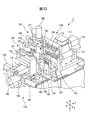
- FIG. 10 is a view showing an example of a machine tool on which the back surface tool holding device 60 can be mounted
- FIG. 11 is a view showing a state where the back surface tool holding device 60 is mounted on the machine tool.
- the front main spindle unit 110 of the machine tool 2 has a front main spindle stand 111 on which a front main spindle can be rotatably driven, and a guide bush 112 for holding the work rotatably and slidably.
- the front spindle stock 111 is moved in the Z direction by the front spindle moving device 114 via the front Z axis rail 113 extending in the Z direction.
- the front main spindle is rotated by, for example, an electric motor built in the front main spindle block 111.
- the front tool holding unit 120 has an opposing blade moving device 121, a first opposing blade moving shaft 122, an opposing blade movement transfer member 123, and a second opposing blade moving shaft 124.
- the opposing blade moving device 121 has a motor, and an opposing blade base and a back main shaft (not shown) in the Y direction via the first opposing blade moving shaft 122, the opposing blade movement transfer member 123 and the second opposing blade moving shaft 124. Move it.
- the back spindle unit 130 has a back spindle 131 on which the back spindle 132 is rotatably mounted.
- the back spindle block 131 is connected by a first back spindle moving device 134 and a second back spindle moving device 136 via a back X axis rail 133 extending in the X direction and a back Z axis rail 135 extending in the Z direction. It moves in the X and Z directions.
- the rear headstock 131 incorporates a motor and rotates the rear main spindle.
- the back surface tool holding portion 140 has a back surface tool device 141, a back surface base 142, and a back surface plate 143.
- the back tooling device 141 has an electric motor, and rotates the first shaft 62 a and the second shaft 62 b of the back tool holding device 60.
- the tool rest 150 of the machine tool 2 is engaged with the rotary tool 151 for rotating the rotary tool 160, the rotary tool spindle holding portion 152 for movably holding the rotary tool spindle, and the rotary tool spindle, and rotates the rotary tool 160. And a rotary tool holder 153 for possible holding.
- the tool rest 150 further includes an X-axis rail 154 which extends in the X direction and slidably holds the rotary tool spindle holding portion 152, and an X axis moving device 155 which moves the rotary tool spindle holding portion 152 in the X direction.
- the tool rest 150 further has a Y-spindle moving device 156 for moving the rotating tool main-spindle holder 152 in the Y direction.
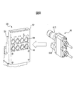
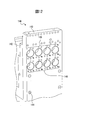
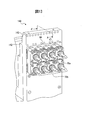
- FIG. 12 is a partial perspective view of the back tool holder 140 with the back tool holder 60 not mounted
- FIG. 13 is a partial perspective view of the back tool holder 140 with the back tool holder 60 mounted. It is.
- the back plate 143 is formed with four through holes 145 and four non-through holes 146.
- Each of the four through holes 145 is a cylindrical hole penetrating from one surface of the back plate 143 to the other surface.
- a recess is formed on the surface of the back base 142 corresponding to the through hole 145.
- the four non-through holes 146 are cylindrical recesses having a circular bottom.
- each of the four back surface tool holding devices 60 the first projection 615 is accommodated in the through hole 145, the second projection 616 is accommodated in the non-through hole 146, and the back surface tool holding portion by a fastening member such as a screw. It is attached to the back surface tool holding part 140 by being fastened at 140. Further, each of the four back surface tool holding devices 60 holds the first rotary tool 70 a at a position corresponding to the through hole 145 and holds the second rotary tool 70 b at a position corresponding to the non-through hole 146.
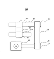
- FIG. 14 is a cross-sectional view taken along the line AA 'of FIG.
- the back tool holding device 60 in the machine tool 2 is similar to that in the case of being held by the machine tool 1 except that the back tool holding device 60 is held by the back tool holding portion 140 instead of the back tool stand 50. I omit it.
- the back surface tool holding device 60 is a tool holding device used for processing a work held by the back surface spindle, but the tool holding device according to the embodiment is a work held by the front surface spindle It may be a front tool holding device used for processing of.
- the back tool holding device 60 rotates in response to the rotation of the first shaft 62a below the first shaft 62a on which the driving force input unit 66 is disposed at the end. 62b is placed.
- the second shaft that rotates in response to the rotation of the first shaft may be disposed above the first shaft in which the driving force input unit is disposed at the end.
Abstract
La présente invention concerne un dispositif de support d'outil comprenant : un boîtier qui a une première surface, une seconde surface opposée à la première surface, et une première saillie et une seconde saillie qui dépassent de la seconde surface dans une direction opposée à la première surface ; une première partie de support d'outil qui se trouve dans une position, sur la première surface, opposée à la première saillie ; une seconde partie de support d'outil qui se trouve dans une position, sur la première surface, opposée à la seconde saillie ; une unité d'entrée de force d'entraînement qui se trouve au niveau de la pointe de la première saillie et qui tourne en fonction d'une force d'entraînement appliquée à celle-ci ; un premier arbre qui s'étend dans une direction axiale perpendiculaire à la première surface et à la seconde surface et qui a une extrémité sur laquelle l'unité d'entrée de force d'entraînement est disposée et l'autre extrémité sur laquelle la première partie de support d'outil est disposée ; un second arbre qui s'étend dans la direction axiale et qui a une extrémité logée dans la seconde saillie et l'autre extrémité sur laquelle la seconde partie de support d'outil est disposée ; et une unité de transmission de rotation qui fait tourner le second arbre en association avec la rotation du premier arbre.
Priority Applications (5)
| Application Number | Priority Date | Filing Date | Title |
|---|---|---|---|
| CN201880082253.4A CN111542408B (zh) | 2017-12-22 | 2018-07-06 | 工具保持装置及机床 |
| JP2019560023A JP7234136B2 (ja) | 2017-12-22 | 2018-07-06 | 工具保持装置及び工作機械 |
| US16/772,779 US11376697B2 (en) | 2017-12-22 | 2018-07-06 | Tool holding device and machine tool |
| EP18891871.8A EP3730239B1 (fr) | 2017-12-22 | 2018-07-06 | Dispositif de support d'outil et machine-outil |
| KR1020207013331A KR102542884B1 (ko) | 2017-12-22 | 2018-07-06 | 공구보유장치 및 공작기계 |
Applications Claiming Priority (2)
| Application Number | Priority Date | Filing Date | Title |
|---|---|---|---|
| US201762610093P | 2017-12-22 | 2017-12-22 | |
| US62/610,093 | 2017-12-22 |
Publications (1)
| Publication Number | Publication Date |
|---|---|
| WO2019123699A1 true WO2019123699A1 (fr) | 2019-06-27 |
Family
ID=66994682
Family Applications (1)
| Application Number | Title | Priority Date | Filing Date |
|---|---|---|---|
| PCT/JP2018/025753 WO2019123699A1 (fr) | 2017-12-22 | 2018-07-06 | Dispositif de support d'outil et machine-outil |
Country Status (6)
| Country | Link |
|---|---|
| US (1) | US11376697B2 (fr) |
| EP (1) | EP3730239B1 (fr) |
| JP (1) | JP7234136B2 (fr) |
| KR (1) | KR102542884B1 (fr) |
| CN (1) | CN111542408B (fr) |
| WO (1) | WO2019123699A1 (fr) |
Families Citing this family (2)
| Publication number | Priority date | Publication date | Assignee | Title |
|---|---|---|---|---|
| JP7467080B2 (ja) * | 2019-11-20 | 2024-04-15 | シチズン時計株式会社 | チャック装置 |
| JP2023549283A (ja) | 2020-08-07 | 2023-11-22 | 株式会社エキソステムテック | ブロッコリーエクソソームを有効成分として含む抗老化、抗酸化化粧料組成物、及びそれを含む機能性化粧品 |
Citations (4)
| Publication number | Priority date | Publication date | Assignee | Title |
|---|---|---|---|---|
| JPS60228004A (ja) * | 1984-04-26 | 1985-11-13 | Nissan Motor Co Ltd | タレツト形切削加工ユニツト |
| JPH0537430U (ja) | 1991-10-16 | 1993-05-21 | オークマ株式会社 | 正面・側面加工兼用回転工具軸ユニツト |
| JPH06226519A (ja) * | 1993-02-02 | 1994-08-16 | Honda Motor Co Ltd | タレット型工作機械 |
| JP5579799B2 (ja) | 2012-07-31 | 2014-08-27 | 株式会社オーエム製作所 | 複合加工機 |
Family Cites Families (25)
| Publication number | Priority date | Publication date | Assignee | Title |
|---|---|---|---|---|
| US1700975A (en) | 1926-04-17 | 1929-02-05 | Joseph F Buhr | Drill head |
| DE1752463A1 (de) | 1968-05-30 | 1971-11-18 | Hueller Gmbh K | Vielspindelwerkzeugmaschine |
| GB1248976A (en) * | 1968-11-08 | 1971-10-06 | Firth Cleveland Eng | Improvements in or relating to multi-spindle tool heads |
| US3635570A (en) * | 1970-06-01 | 1972-01-18 | Cameron Machine Co | Apparatus for drilling drive pin holes in rewind roll cores |
| AT311029B (de) | 1971-02-12 | 1973-10-25 | Kuper Heinrich Fa | Mehrspindel-Bohrvorrichtung |
| JPH03142144A (ja) * | 1989-10-26 | 1991-06-17 | Sugino Mach Ltd | オイルホール付工具取付ユニット |
| JPH0537430A (ja) | 1991-07-31 | 1993-02-12 | Toshiba Corp | 車載用テレビ装置 |
| US5471724A (en) * | 1994-08-23 | 1995-12-05 | Thermwood Corporation | Toolhead assembly for machine tools |
| JPH08300208A (ja) * | 1995-05-01 | 1996-11-19 | Eguro Tekkosho:Kk | 多軸ボール盤 |
| JPH09225739A (ja) * | 1996-02-27 | 1997-09-02 | Hitachi Seiko Ltd | 多軸ヘッド |
| JP3684100B2 (ja) * | 1999-03-19 | 2005-08-17 | 株式会社スギノマシン | 簡易型ドリル加工ユニット |
| US6412156B1 (en) * | 1999-05-21 | 2002-07-02 | Toyoda Koki Kabushiki Kaisha | Multi-spindle machine tool |
| IT1321262B1 (it) * | 2000-05-16 | 2004-01-08 | Biesse Spa | Testa di foratura per macchine per la lavorazione di pannelli dilegno o similari. |
| JP4179775B2 (ja) * | 2001-11-26 | 2008-11-12 | 株式会社牧野フライス製作所 | 工作機械の主軸の交換方法 |
| US8128323B2 (en) * | 2009-04-14 | 2012-03-06 | Planet Products Corporation | Driven tool assembly |
| TWM368499U (en) * | 2009-06-11 | 2009-11-11 | Protean Machine Ind Co Ltd | An outer ring bearing rotation preventing device of an aluminum extrusion type multi-axis hole drilling base |
| WO2014087491A1 (fr) | 2012-12-04 | 2014-06-12 | 上野精機株式会社 | Dispositif de transfert |
| CN103286328B (zh) | 2013-05-09 | 2016-01-27 | 沈阳第一机床厂 | 双主轴的卧式数控车床 |
| DE102013013050B4 (de) | 2013-07-29 | 2023-04-13 | Alfing Kessler Sondermaschinen Gmbh | Werkzeugmaschine mit mehreren Mehrspindel-Spindelbaugruppen |
| CN104162691B (zh) * | 2014-07-28 | 2016-08-24 | 佛山市旭川机械有限公司 | 动力刀塔装置及数控车床 |
| TWM510805U (zh) | 2015-01-06 | 2015-10-21 | Chen Peng Ren | Cnc雙主軸傳動裝置 |
| JP6753847B2 (ja) | 2015-06-02 | 2020-09-09 | シチズン時計株式会社 | 工作機械 |
| CN106392113A (zh) | 2016-12-23 | 2017-02-15 | 东莞市台科精密机械有限公司 | 一种轴向摆角动力刀塔 |
| JP6774343B2 (ja) * | 2017-01-23 | 2020-10-21 | 株式会社スギノマシン | 工作機械 |
| US11975414B2 (en) * | 2018-08-23 | 2024-05-07 | Citizen Watch Co., Ltd. | Tool rest and machine tool |
-
2018
- 2018-07-06 WO PCT/JP2018/025753 patent/WO2019123699A1/fr unknown
- 2018-07-06 US US16/772,779 patent/US11376697B2/en active Active
- 2018-07-06 CN CN201880082253.4A patent/CN111542408B/zh active Active
- 2018-07-06 EP EP18891871.8A patent/EP3730239B1/fr active Active
- 2018-07-06 KR KR1020207013331A patent/KR102542884B1/ko active IP Right Grant
- 2018-07-06 JP JP2019560023A patent/JP7234136B2/ja active Active
Patent Citations (4)
| Publication number | Priority date | Publication date | Assignee | Title |
|---|---|---|---|---|
| JPS60228004A (ja) * | 1984-04-26 | 1985-11-13 | Nissan Motor Co Ltd | タレツト形切削加工ユニツト |
| JPH0537430U (ja) | 1991-10-16 | 1993-05-21 | オークマ株式会社 | 正面・側面加工兼用回転工具軸ユニツト |
| JPH06226519A (ja) * | 1993-02-02 | 1994-08-16 | Honda Motor Co Ltd | タレット型工作機械 |
| JP5579799B2 (ja) | 2012-07-31 | 2014-08-27 | 株式会社オーエム製作所 | 複合加工機 |
Non-Patent Citations (1)
| Title |
|---|
| See also references of EP3730239A4 |
Also Published As
| Publication number | Publication date |
|---|---|
| EP3730239B1 (fr) | 2024-01-17 |
| US11376697B2 (en) | 2022-07-05 |
| EP3730239A1 (fr) | 2020-10-28 |
| KR102542884B1 (ko) | 2023-06-14 |
| TW201927458A (zh) | 2019-07-16 |
| KR20200099518A (ko) | 2020-08-24 |
| EP3730239A4 (fr) | 2021-09-15 |
| JP7234136B2 (ja) | 2023-03-07 |
| CN111542408A (zh) | 2020-08-14 |
| US20200331072A1 (en) | 2020-10-22 |
| CN111542408B (zh) | 2023-05-26 |
| JPWO2019123699A1 (ja) | 2020-12-10 |
Similar Documents
| Publication | Publication Date | Title |
|---|---|---|
| US10239129B2 (en) | Machine tool | |
| WO2015079836A1 (fr) | Machine-outil et procédé de coupe | |
| JP6217856B2 (ja) | 工作機械及び加工方法 | |
| JP5891107B2 (ja) | 工作機械 | |
| JP5937486B2 (ja) | 工作機械 | |
| JP5313533B2 (ja) | 工具用スピンドルとチャック用スピンドルのいずれも取り付け可能な主軸ユニット | |
| WO2019123699A1 (fr) | Dispositif de support d'outil et machine-outil | |
| JP2009233786A5 (fr) | ||
| WO2019202779A1 (fr) | Outil d'usinage | |
| KR20150117182A (ko) | 키홈 가공장치 | |
| WO2016013307A1 (fr) | Machine-outil, unité d'outil, et procédé d'usinage | |
| US8978219B2 (en) | Machine tool | |
| JP2002011616A (ja) | 歯切工具及び歯切加工方法 | |
| JPH1015703A (ja) | 多機能旋盤 | |
| TWI834618B (zh) | 工具保持裝置及工作機械 | |
| JP7441678B2 (ja) | 回転工具装置および工作機械 | |
| JP2001322001A (ja) | 複合加工旋盤 | |
| JP2019076974A (ja) | 旋盤用工具ホルダ及びこの工具ホルダを備えた旋盤 | |
| JP7324848B2 (ja) | 工作機械 | |
| JPH05318206A (ja) | Nc旋盤及びその制御方法 | |
| JPH09155667A (ja) | 旋回多軸スピンドルヘッド装置 | |
| KR20090123769A (ko) | 수직형 비티에이 드릴링 머신 | |
| JP2005028481A (ja) | 工作機械 | |
| JP2019171491A (ja) | 工作機械、工具モジュール及び切削加工方法 | |
| JP2005169524A (ja) | 自動旋盤 |
Legal Events
| Date | Code | Title | Description |
|---|---|---|---|
| 121 | Ep: the epo has been informed by wipo that ep was designated in this application |
Ref document number: 18891871 Country of ref document: EP Kind code of ref document: A1 |
|
| ENP | Entry into the national phase |
Ref document number: 2019560023 Country of ref document: JP Kind code of ref document: A |
|
| NENP | Non-entry into the national phase |
Ref country code: DE |
|
| ENP | Entry into the national phase |
Ref document number: 2018891871 Country of ref document: EP Effective date: 20200722 |