WO2019045119A1 - 画像形成装置 - Google Patents
画像形成装置 Download PDFInfo
- Publication number
- WO2019045119A1 WO2019045119A1 PCT/JP2018/032791 JP2018032791W WO2019045119A1 WO 2019045119 A1 WO2019045119 A1 WO 2019045119A1 JP 2018032791 W JP2018032791 W JP 2018032791W WO 2019045119 A1 WO2019045119 A1 WO 2019045119A1
- Authority
- WO
- WIPO (PCT)
- Prior art keywords
- duct
- image forming
- filter
- forming apparatus
- sheet
- Prior art date
- Legal status (The legal status is an assumption and is not a legal conclusion. Google has not performed a legal analysis and makes no representation as to the accuracy of the status listed.)
- Ceased
Links
Images


Classifications
-
- G—PHYSICS
- G03—PHOTOGRAPHY; CINEMATOGRAPHY; ANALOGOUS TECHNIQUES USING WAVES OTHER THAN OPTICAL WAVES; ELECTROGRAPHY; HOLOGRAPHY
- G03G—ELECTROGRAPHY; ELECTROPHOTOGRAPHY; MAGNETOGRAPHY
- G03G21/00—Arrangements not provided for by groups G03G13/00 - G03G19/00, e.g. cleaning, elimination of residual charge
- G03G21/0005—Arrangements not provided for by groups G03G13/00 - G03G19/00, e.g. cleaning, elimination of residual charge for removing solid developer or debris from the electrographic recording medium
- G03G21/0052—Arrangements not provided for by groups G03G13/00 - G03G19/00, e.g. cleaning, elimination of residual charge for removing solid developer or debris from the electrographic recording medium using an air flow; Details thereof, e.g. nozzle structure
-
- G—PHYSICS
- G03—PHOTOGRAPHY; CINEMATOGRAPHY; ANALOGOUS TECHNIQUES USING WAVES OTHER THAN OPTICAL WAVES; ELECTROGRAPHY; HOLOGRAPHY
- G03G—ELECTROGRAPHY; ELECTROPHOTOGRAPHY; MAGNETOGRAPHY
- G03G21/00—Arrangements not provided for by groups G03G13/00 - G03G19/00, e.g. cleaning, elimination of residual charge
- G03G21/20—Humidity or temperature control also ozone evacuation; Internal apparatus environment control
- G03G21/206—Conducting air through the machine, e.g. for cooling, filtering, removing gases like ozone
-
- G—PHYSICS
- G03—PHOTOGRAPHY; CINEMATOGRAPHY; ANALOGOUS TECHNIQUES USING WAVES OTHER THAN OPTICAL WAVES; ELECTROGRAPHY; HOLOGRAPHY
- G03G—ELECTROGRAPHY; ELECTROPHOTOGRAPHY; MAGNETOGRAPHY
- G03G15/00—Apparatus for electrographic processes using a charge pattern
- G03G15/65—Apparatus which relate to the handling of copy material
- G03G15/6555—Handling of sheet copy material taking place in a specific part of the copy material feeding path
- G03G15/657—Feeding path after the transfer point and up to the fixing point, e.g. guides and feeding means for handling copy material carrying an unfused toner image
-
- G—PHYSICS
- G03—PHOTOGRAPHY; CINEMATOGRAPHY; ANALOGOUS TECHNIQUES USING WAVES OTHER THAN OPTICAL WAVES; ELECTROGRAPHY; HOLOGRAPHY
- G03G—ELECTROGRAPHY; ELECTROPHOTOGRAPHY; MAGNETOGRAPHY
- G03G2215/00—Apparatus for electrophotographic processes
- G03G2215/20—Details of the fixing device or porcess
- G03G2215/2093—Release agent handling devices
-
- G—PHYSICS
- G03—PHOTOGRAPHY; CINEMATOGRAPHY; ANALOGOUS TECHNIQUES USING WAVES OTHER THAN OPTICAL WAVES; ELECTROGRAPHY; HOLOGRAPHY
- G03G—ELECTROGRAPHY; ELECTROPHOTOGRAPHY; MAGNETOGRAPHY
- G03G2221/00—Processes not provided for by group G03G2215/00, e.g. cleaning or residual charge elimination
- G03G2221/0026—Cleaning of foreign matter, e.g. paper powder, from imaging member
- G03G2221/0068—Cleaning mechanism
- G03G2221/0094—Suction
Definitions
- the present invention relates to an image forming apparatus such as a copying machine, a printer, a facsimile, and a multifunction peripheral having a plurality of these functions for forming a toner image on a sheet.
- the release agent (wax) contained in the toner is temporarily heated to have a particle size of 100 nm or less temporarily. It is known to be in the state of JP-A-2011-180340 proposes that a filter be installed in a path exhausted to the outside by an exhaust duct to collect such dust.
- An object of the present invention is to enhance the dust reduction effect.
- an image forming unit for forming a toner image on a sheet at a first position using a toner containing a releasing agent; and a toner image formed on the sheet by the image forming unit
- a fixing unit for heat fixing at a second position; and an air inlet disposed opposite to the sheet conveyance path between the first position and the second position, and exhausting the image forming apparatus
- An image forming apparatus is provided having an engagement portion which is capable of engaging with the duct.
- FIG. 1 is an enlarged cross-sectional view taken along line (a)-(a) of FIG. 8, and (b) shows a state in which a frame member with a filter is removed from the duct in (a).
- FIG. 2 is a schematic view of an example of the image forming apparatus.
- FIG. 3 is a partially enlarged schematic view of the main part of FIG.
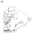
- FIG. 4 is a view showing a state in which the open / close door is opened.
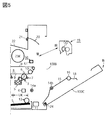
- FIG. 5 is an explanatory view of attachment and detachment of the fixing device.
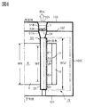
- FIG. 6 is a schematic diagram of (6)-(6) line arrow in FIG.
- FIG. 7 is an external perspective view of a duct unit.
- FIG. 8 is an enlarged plan view of one longitudinal end of the duct unit.
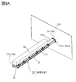
- FIG. 9A is a perspective view of a duct unit mounted at a predetermined mounting position of the apparatus main body.
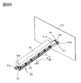
- FIG. 9B is an explanatory view of a procedure of attaching and detaching the duct unit.
- FIG. 9C is an explanatory view of a procedure for taking in and out the duct unit from the apparatus body.
- FIG. 10 is an explanatory view of a disengagement state of the first engagement portion with respect to the first engaged portion.
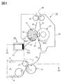
- FIG. 2 is a schematic front view of the image forming apparatus 100 in the present embodiment.
- the front side (front side, front side) of the image forming apparatus 100 is the front side
- the rear side (rear side, back side) is the opposite side in the plane of FIG.
- Left and right are left and right when the apparatus 100 is viewed from the front.
- Upper and lower are upper and lower in the direction of gravity.
- the upstream side and the downstream side are the upstream side and the downstream side in the sheet conveying direction.
- This image forming apparatus is a tandem-intermediate transfer four-color full-color laser printer using an electrophotographic process, and image information input from an external host device (not shown) such as a personal computer to a control circuit unit (not shown) Forms a toner image on the sheet S based on an external host device (not shown) such as a personal computer to a control circuit unit (not shown)
- the image forming unit 1 inside the image forming apparatus main body (apparatus frame: hereinafter referred to as an apparatus main body) 100A has first to fourth four image forming units U (UY, UM, UC, UK).
- the image forming unit 1 also has an intermediate transfer belt unit 8 and a sheet cassette 11 on the upper side and the lower side of the first to fourth image forming units U, respectively.
- the first to fourth image forming units U are four color toners obtained by adding a black (K) color to a yellow (Y) color, a magenta (M) color, a cyan (C) color which is three subtractive primary colors Each forms an image.
- Each image forming unit U has a rotating drum type electrophotographic photosensitive member (hereinafter referred to as a drum) 2 as an image carrier.
- the image forming apparatus further includes a charging roller 3, a laser scanner (exposure device) 4, a developing device 5, a primary transfer roller 6, and a drum cleaner 7 as process means acting on the drum 2.
- the toner images of the respective colors are superimposed in a predetermined manner on the intermediate transfer belt (intermediate transfer member) 9 which rotates from the drums 2 of the first to fourth image forming units U and sequentially primary-transferred. As a result, a toner image of four-color superposition of Y + M + C + K is formed on the belt 9.
- an upward transport path 12 for transporting the sheet S from the bottom to the top is disposed.
- a sheet feeding roller 13, registration roller pairs 14a and 14b, a secondary transfer roller 16, a fixing device (fixing device) 19, and a discharge roller 21 are disposed in this conveying path 12 in order from the lower side to the upper side.
- the secondary transfer roller 16 contacts the belt winding roller 10 on the right side of the intermediate transfer belt unit 8 with a predetermined pressing force via the belt 9 to form the belt 9 and the secondary transfer nip portion 17 .
- Reference numerals 15, 18 and 20 denote guide members for guiding the sheet S in the conveyance path 12.
- the guide member 15 is disposed between the registration roller pair 14 a and 14 b and the secondary transfer roller 16.
- the guide member 18 is disposed between the secondary transfer roller 16 and the fixing device 19.
- the guide member 20 is disposed between the fixing device 19 and the discharge roller 21.
- one sheet S is separated and fed from the sheet cassette 11 and introduced into the conveyance path 12. Then, the sheet is introduced into the secondary transfer nip portion 17 at a predetermined control timing by the registration roller pair 14a and 14b, and nipped and conveyed. As a result, the toner images of four colors superimposed on the belt 9 are collectively secondarily transferred and formed on the sheet S at the secondary transfer nip portion 17.
- the sheet S exiting the secondary transfer nip portion 17 is introduced into a fixing device 19 functioning as a fixing portion, and undergoes thermal fixing processing of the toner image.
- the fixing device 19 heats the toner image formed on the sheet S at the secondary transfer nip (first position) 17 of the image forming unit 1 at the fixing nip (second position) N (FIG. 3). And a fixing unit that fixes by pressure.
- the sheet S having exited the fixing device 19 is discharged as an image forming object onto a discharge tray 22 which is an upper surface portion of the apparatus main assembly 100A by a discharge roller pair 21.
- 23Y, 23M, 23C, and 23K are detachably replaceable toner bottles that contain toner for replenishing the developing device 5 of the first to fourth image forming units UY, UM, UC, UK, respectively, and an intermediate transfer belt It is disposed on the upper side of the unit 8.
- An appropriate amount of toner is replenished from the corresponding toner bottle to the developing device 5 of each of the image forming units UY, UM, UC, UK by a toner replenishing mechanism (not shown).
- FIG. 3 is an enlarged schematic view of the secondary transfer nip portion 17 and the fixing device 19 in FIG.
- the fixing device 19 in this embodiment is an on-demand fixing device (ODF fixing device) of a belt heating type-pressure member driving type.
- ODF fixing device on-demand fixing device
- the basic configuration and the fixing operation of the fixing device are known, and therefore the description thereof will be simply omitted.
- the fixing unit 19 is roughly classified into a belt unit 31 provided with a fixing belt (hereinafter referred to as a belt) 32 as a first rotating body, and a pressure roller 33 having elasticity as a second rotating body. It is comprised by the housing
- a fixing nip portion N is formed by the belt 32 and the pressure roller 33. The fixing nip portion N fixes and conveys the sheet S carrying the unfixed toner image by heat and pressure.
- a sheet inlet (sheet inlet) 35 and a sheet outlet 38 are formed in the housing 34.
- the sheet inlet 35 is formed by a first guide member 36 facing the sheet back surface which is the toner image non-bearing surface of the sheet S and a second guide member 37 facing the sheet surface which is the toner image bearing surface.
- the belt unit 31 and the pressure roller 33 are disposed such that the sheet inlet 35 is located below the sheet outlet 38 in the gravity direction.
- the fixing device 19 of the present embodiment is configured to convey the sheet S upward from the lower side in the direction of gravity, and is referred to as a vertical path configuration.
- a fixing heater heat source: hereinafter referred to as a heater
- a heater holder hereinafter referred to as a holder
- a rigid stay hereinafter referred to as a stay
- the heater 39 is a heating source for heating the belt 32.
- the heater 39 is a pressing member when the belt 32 is pressed toward the pressure roller 33.
- As the heater 39 for example, a so-called ceramic heater is used.
- the heater 39 is disposed along the longitudinal direction (width direction) of the belt 32.
- the heater 39 is disposed inside the belt 32 so as to be slidable with the inner surface of the belt 32.
- the heater 39 generates heat when the power is supplied from a power supply unit (not shown), and the temperature rises sharply.
- the temperature of the heater 39 is detected by a temperature sensor (not shown) and fed back to the control circuit (not shown).
- the control circuit unit controls the power supplied from the power supply unit to the heater 39 so that the temperature of the heater 39 is raised to a predetermined target temperature and the temperature is controlled based on the input detected temperature information.
- the holder 40 is a member that holds the heater 39 in the longitudinal direction.
- the holder 40 fixes the heater 39 on the surface on the pressure roller 33 side.
- the holder 40 is a guide member for guiding the circumferential curvature of the belt 32 so that the sheet S can be easily separated from the belt 32.
- the holder 40 is desirably excellent in heat resistance, and for example, a liquid crystal polymer resin can be used.
- the stay 41 is a support member for supporting the holder 40 and the heater 39 in the longitudinal direction.
- the stay 41 is disposed on the opposite side of the pressure roller 33 with the holder 40, the heater 39, and the belt 32 therebetween. Both ends of the stay 41 in the longitudinal direction are pressed toward the pressure roller 33 with a predetermined pressure.
- the stay 41, the holder 40, and the heater 39 press the belt 32 toward the pressure roller 33 side.
- the elastic rubber layer is elastically deformed to be shaped according to the surface of the heater 39.
- a fixing nip N having a predetermined width in the sheet conveying direction is formed between the belt 32 and the pressure roller 33.
- the pressure roller 33 is disposed such that the rotational axis direction (longitudinal direction) thereof is substantially parallel to the longitudinal direction (the generatrix direction) of the belt 32.
- both end portions in the longitudinal direction of the cored bar are rotatably held by side plates (not shown) on the front and back sides of the housing 34 via bearings.
- the core metal of the pressure roller 33 is connected to a drive mechanism (not shown) including a motor which is a drive source, and is rotationally driven at a predetermined circumferential speed in the clockwise direction of arrow R33 by the drive of the motor.
- the drive of the pressure roller 33 is transmitted by the frictional force at the fixing nip portion N, and the belt 32 in pressure contact at the fixing nip portion N is pressed in the counterclockwise direction indicated by the arrow R32.
- the roller 33 is driven to rotate.
- the fixing unit 19 is located above the intermediate transfer belt 9 in the direction of gravity, and the fixing nip N is located above the secondary transfer nip 17 in the direction of gravity. Accordingly, the sheet S having exited the secondary transfer nip portion 17 is conveyed upward and is introduced to the fixing device 19 from the bottom to the top.
- the guide members 18, 36, 37 for conveying the sheet S from the secondary transfer nip portion 17 to the fixing nip portion N are formed with an inclined surface or a curved surface so that the sheet S is not caught. So as to securely guide the sheet S.
- the sheet S receives heat of the heater 39 through the belt 32.
- the unfixed toner image is melted by the heat of the heater 39 and fixed by the pressure applied to the fixing nip N.
- the sheet S nipped and conveyed by the fixing nip portion N leaves the fixing device 19 from the sheet outlet 38 via the guide member 42 and the in-fixing discharge roller pair 43. Further, the sheet is sent onto the discharge tray 22 by the discharge roller pair 21 via the guide member 20. (Opening door)
- an opening 100B is provided on the right side of the apparatus main body 100A as an access port at the time of processing a jammed sheet, maintenance of the inside of the apparatus, and the like.
- An open / close door 100C movable between a predetermined closed position A (FIG. 2) for closing the opening 100B and a predetermined open position B (FIG. 4) for opening the opening 100B is provided.
- the open / close door 100C can be opened and closed about the lower hinge shaft 24 as a rotation center.
- the open / close door 100C When the open / close door 100C is sufficiently closed with respect to the apparatus main body 100A to the closed position A as shown in FIG. 2, the open / close door 100C is held open by the lock operation of the lock mechanism (not shown).
- the image forming apparatus 100 can perform an image forming operation in a state where the open / close door 100C is closed.
- the open / close door 100C can be fully opened and rotated from the closed position A of FIG. 2 to the open position B as shown in FIG. 4 by unlocking of the lock mechanism.
- One roller 14b of the pair of resist rollers 14a and 14b, the guide member 15, the secondary transfer roller 16, and the guide member 18 in the upward conveying path 12 which conveys the sheet S upward from the bottom inside the opening / closing door 100C. Is provided. Accordingly, by opening the open / close door 100C, the transport path 12 is largely opened at the opening 100B on the right side of the apparatus body 100A.
- the fixing unit 19 is detachably mounted to a predetermined mounting portion (not shown) inside the apparatus main body 100A by a hooking structure or the like. Accordingly, as shown in FIG. 5, the inside of the apparatus can be accessed easily from the opening 100B opened by opening the open / close door 100C and screwless, as shown in FIG. (Mechanism of UFP occurrence)
- the fixing device 19 fixes the toner image by bringing the sheet S into contact with the belt 32, which is a high temperature fixing member.
- the fixing process is performed using such a configuration, a part of the toner may be transferred (adhered) to the belt 32 during the fixing process. This is called an offset phenomenon, but a countermeasure is essential because the offset phenomenon causes an image defect.
- the toner used in the image forming apparatus contains a wax as a release agent.
- the internal wax dissolves and exudes, so that when the toner image is subjected to a fixing process, the surface of the belt 32 is covered with the melted wax.
- the belt 32 whose surface is covered with wax has an effect of making it difficult for the toner to adhere due to the releasing action of the wax.
- a compound containing a molecular structure of wax in addition to pure wax, is also called wax.
- a compound in which a resin molecule of a toner and a wax molecular structure such as a hydrocarbon chain have reacted is also referred to as a wax.
- a substance having a release effect such as silicone oil may be used.
- the wax When the wax is melted, part of it evaporates (volatilizes). It is considered that this is because there is a variation in the size of the molecular component contained in the wax. That is, the wax contains a low molecular weight component having a short chain and a low boiling point and a high molecular weight component having a long chain and a high boiling point, and it is considered that the low molecular weight component having a low boiling point evaporates first.
- fine particles with a predetermined particle size severe nm to several hundreds of nm
- are generated Specifically, fine particles having a particle diameter of 5.6 nm or more and 560 nm or less. That is, this particle is the UFP mentioned above.
- UFP is generated by the above mechanism, it can be seen that UFP is generated most from the fixing nip N which applies heat to the wax. Further, since it is on the upstream side of the fixing nip N from the rotation of the belt 32, the arrangement of the heater 39, etc. that the belt 32 becomes the highest temperature, the occurrence of UFP also becomes the maximum upstream of the fixing nip N Can be guessed. Furthermore, since UFP is generated from the toner image transferred to the sheet S, it is also understood that the UFP is generated from the entire image area of the fixing nip N. (UFP reduction configuration)
- the reduction of the UFP which is a fine particle having a particle diameter of 5.6 nm or more and 560 nm or less, collects the UFP generated using the filter and the air suction disposed in the device main body. Therefore, it becomes possible to reduce the amount of UFP discharged to the outside of the aircraft.
- the filters are arranged in the vicinity of the image area on the upstream side of the fixing nip N, which is the maximum occurrence position of UFP. It is obvious from the mechanism of UFP generation described in detail above that if UAP can be collected most efficiently if air suction can be uniformly performed over the entire area in the longitudinal direction of the filter.
- reference numeral 50 denotes a duct unit as a UFP reducing structure in the image forming apparatus 100 of this embodiment.
- FIG. 6 is a schematic view taken along line (6)-(6) in FIG.
- the duct unit 50 is located between the secondary transfer portion (first position) 17 of the image forming portion 1 and the fixing nip portion (second position) N of the fixing portion 19.
- the duct unit 50 has an intake port 52, a filter 53 for collecting (filtering) UFP (particles derived from a mold release agent (wax)), and a duct 51 having an exhaust port 54 for exhausting air from the outside.
- the duct 51 in the present embodiment is a hollow body having a substantially rectangular cross section, which is long along the length of the fixing device 19.
- the intake port 52 is formed as an opening along the longitudinal direction on one side surface of the duct 51 in the longitudinal direction. That is, the intake port 52 extends in the longitudinal direction of the fixing nip portion N.
- the filter 53 is disposed to cover the air inlet 52. That is, the filter 53 is a flat member formed so as to extend in the direction orthogonal to the sheet conveyance direction in the longitudinal direction, and is fixed to the air inlet 52.
- the filter 53 is fixed to a frame member that functions as a detachable holder for the duct 51. The frame member will be described later.
- One end (front end) of the duct 51 is closed, and the other end (rear end) is expanded as a trumpet-shaped duct portion 51A and opened as an exhaust port 54.
- the first rear plate 102 and the second rear plate disposed at a predetermined distance from this are arranged. It has 103.
- a first opening 104 and a second opening 105 opposed to each other are disposed in the first back surface plate 102 and the second back surface plate 103.
- the first opening 104 and the second opening 105 are connected by a fan duct 51B in which a fan F is incorporated.
- the duct unit 50 is located at a predetermined mounting position between the front plate 101 and the first rear plate 102 inside the apparatus main body 100A, with the front end portion facing the front plate 101 and the rear end as the first rear plate 102. It is detachably fixed to the main assembly 100A of the apparatus. The attachment configuration of the duct unit 50 to the apparatus body 100A will be described later.
- the exhaust port 54 at the rear end of the duct 51 corresponds to the first opening 104 disposed in the first back surface plate 102 in a state where the duct unit 50 is attached to the apparatus main body 100A in a predetermined manner. It agrees.
- the exhaust port 54 of the duct 51 communicates with the outside on the back side of the apparatus main body 100A through the first opening 104 ⁇ the fan duct 51B ⁇ the second opening 105.
- the fan F is controlled by a control circuit unit (not shown). When the fan F is driven, an air flow is generated in the duct 51, and the air in the duct 51 is exhausted from the exhaust port 54 to the outside of the machine through the above path. Thus, air is drawn into the duct 51 from the air inlet 52 covered by the filter 53.
- the duct 51 is disposed on the side of the belt unit 31 of the fixing device 16 (on the side of the first rotating body 32 provided with the heat source 39) between the secondary transfer portion 17 and the fixing nip portion N.
- the intake port 52 covered by the filter 43 of the duct 51 is located closer to the fixing nip N than the middle between the secondary transfer portion 17 and the fixing nip N, and further, the fixing nip It is located near N.
- the intake port 52 covered by the filter 53 is disposed in the vicinity of the upstream side of the fixing nip portion N and on the back side of the guide member 37. That is, the guide member 37 exists in front of the frame member 55 ((a) in FIG. 1) described later, which fixes the filter 53 of the duct unit 50.
- the duct unit 50 configured as described above is a duct while filtering the air including the UFP between the secondary transfer portion 17 and the fixing nip N from the intake port 52 covered by the filter 53 by the drive of the fan F with the filter 53. Inhale into 51.
- the air from which the UFP is filtered by the filter 53 is exhausted to the outside of the machine along the path of the exhaust port 54 ⁇ the first opening 104 ⁇ the fan duct 51 B ⁇ the second opening 105. That is, the UFP discharged out of the machine by the duct unit 50 is reduced.
- the intake port 52 has a fixed length in the direction perpendicular to the sheet conveyance direction.
- the UFP generated from the wax transferred from the toner image of the sheet S to the belt 32 can be reliably collected in the longitudinal direction (width direction) of the belt 32.
- W52 is the longitudinal length of the air inlet 52
- WT is the width of the image formable area on the sheet (maximum image width).
- W 9 is the width of the intermediate transfer belt 9. The length W52 of the air inlet 52 is set to exceed the maximum image width WT.
- W52> WT may be satisfied in the width size with the highest usage frequency.
- the longitudinal length W52 of the air inlet 52 can be set so that W52> WT based on the maximum image width T of the minimum width size sheet. That is, the length W52 of the air inlet 52 is a length that covers the maximum image width WT of the sheet S of the minimum width size that can be used for the apparatus.
- the longitudinal length W52 of the air intake port 52 can be set so that W52> WT based on the maximum image width WT of the maximum width size sheet. That is, the length W52 of the air intake 52 is a length that covers the maximum image width WT of the sheet S of the maximum width size that can be used for the apparatus.
- the air inlet 52 is disposed in the vicinity of the belt 32 and at a position facing the sheet S entering the fixing device 19.
- the duct unit 50 can be miniaturized. That is, the intake port 52 is disposed in the vicinity of the belt 32, which is a dust generation point, at the same time as facing the sheet S.
- the duct unit 50 can omit the path for guiding the air from the fixing nip portion N to the air inlet 52, so that the whole can be easily miniaturized.
- a fan F for sucking air into the duct 51 is fixed to the end via the duct 51 in the shortest path. From this, it can be first recognized that the arrangement of the filter 53, the duct 51, and the fan F with respect to the fixing nip N is the shortest path.
- the filter 53 is disposed extending in the longitudinal direction of the intake port 52 of the duct 51, the pressure loss on the upstream side and the downstream side through the filter 53 becomes substantially uniform in the longitudinal direction.
- the suction of the air is also substantially uniform in the front in the longitudinal direction. That is, the air volume distribution along the longitudinal direction of the air intake of the air taken in by the air intake 52 is substantially uniform.
- the suction force of the air can be lowered, and the cost and size of the fan F can be reduced.
- the UFP reduction configuration can be arranged at low cost, space saving and high efficiency. (Detailed configuration of duct unit)
- the guide member 37 in front of the filter 53, it is devised to prevent the conveyed sheet S from coming into direct contact with the filter 53, but in the case where a curl or the like is attached, etc.
- transport may be violent.
- the sheet S vibrates during conveyance because it does not smoothly enter the fixing nip portion N, and a small amount of toner scatters from the unfixed toner image formed on the sheet, and the surface of the filter 53 is formed. It will be deposited.
- the collection area of the filter 53 for collecting UFP is reduced, and the reduction effect of UFP is reduced. Therefore, the UFP reduction effect of the filter 53 is quickly reduced depending on the usage conditions of the user, such as outputting a large amount of toner image or using a sheet that is prone to run out during conveyance. Therefore, in order to maintain the initial performance of the filter 53, it is predicted that the filter exchange should be performed frequently.
- FIG. 7 is an external perspective view of the duct unit 50 as a whole.
- FIG. 8 is an enlarged plan view of one longitudinal end of the duct unit 50. As shown in FIG. (A) of FIG. 1 is an enlarged cross-sectional view taken along line (a)-(a) of FIG. 8, (b) is removed from the duct 51 in (a) from the frame member 55 with the filter 53 fixed.
- FIG. 6 is an enlarged cross-sectional view showing a separated state (a separated state).
- the duct unit 50 has a duct 51 having an intake port 52 and an exhaust port 54, a filter 53 for collecting dust caused by the mold release agent, and a frame member 55 to which the filter 53 is fixed.
- the duct 51 is a hollow body having a substantially rectangular cross section along the length of the fixing device 19 as described above.
- the intake port 52 is formed as an opening along the longitudinal direction on one side surface of the duct 51 in the longitudinal direction. That is, the intake port 52 extends in the longitudinal direction of the fixing nip portion N.
- One end side (front end) of the duct 51 is closed, and the other end side (rear end) is opened as an exhaust port 54.
- a fan duct 51B (FIG. 6) having a fan F as a member on the apparatus body side is disposed. That is, the duct unit 50 communicates with the fan duct 51B on the apparatus main body side having the fan F.
- the filter 53 is fixed to the frame member 55, and the frame member 55 is detachably fixed to the air inlet 52 of the duct 51.
- the frame member 55 extends in the longitudinal direction of the intake port 52 corresponding to the intake port 52.
- the filter 53 is a flat filter formed to extend in a direction perpendicular to the sheet conveyance direction in the longitudinal direction, whereby the filter 53 is disposed so as to cover the entire area of the intake port 52 with the intake port 52. . That is, the duct 51 is provided with an opening, which is the intake port 52, on the side surface, and the intake port 52 is covered with the filter 53.
- the filter 53 is fixed to the frame member 55 by double-sided tape or thermal welding, and the frame member 55 is attached to the air inlet 52 of the duct 51, whereby the air inlet 52 is covered with the filter 53 without a gap. .
- the filter fixing surface 55b of the frame member 55 is the minimum range of only the filter end 53a. That is, it is considered not to reduce the effective area of the filter 53 facing the outside from the window hole 55a of the frame member 55.
- the shape of the frame member 55 is formed as a ladder-like member provided with a frame-shaped portion which is a fixed surface 55 b of the filter 53 and a cross-tree shape 55 c for preventing the filter 53 from floating and shifting.
- the frame member 55 to which the filter 53 is fixed is attached to and detached from the air inlet 52 of the duct 51.
- the risk of breakage such as breakage due to hooking can be reduced and attachment / detachment becomes easier than attachment / detachment with a single flat sheet-like filter alone.
- an engagement portion which can be easily removed is adopted.
- a hook engaging type engaging portion using a hook portion and a hooked portion is employed.
- hook portions 55d having elasticity are formed on the side of the frame member 55 by hooking on the projecting shapes 51a formed on the upper and lower surfaces of the duct 51 shown in FIG. 1B. It is a so-called snap hook method.
- the filter 53 is fixed to the frame member 55 on the duct 51 side.
- the edge 53a of the filter 53 is sandwiched between the duct 51 and the frame member 55.
- the engaging portion also has a function of compressing the filter 53 by a predetermined amount between the frame member 55 and the duct 51. That is, the gap created between the duct 51 and the frame member 55 is filled with the filter 53, and the tightness of the duct can be guaranteed by this minimum component configuration.
- the filter 53 is attached and detached integrally with the frame member 55 by engaging and disengaging the hook portion 55d of the frame member 55 fixing the filter 53 with the projection shape 51a on the duct 51 side. It can also be seen that it is detachable in the -Y direction. (Installation and removal of duct unit)
- the duct 51 of the duct unit 50 has a first engaging portion 51b and a second engaging portion 51c on one end side (front end) and the other end side (rear end) in the longitudinal direction.
- the device main body 100A is a second engaged portion corresponding to the engaging portion of the first engaged portion 56a corresponding to the first engaging portion 51b and the second engaging portion 51c. It has 102a.
- a fixed base 56 for fixing the duct unit 50 is disposed inside the apparatus main body 100A.
- the fixed base 56 is disposed to the side of the fixing portion inside the apparatus main body 100A.
- the first engaged portion 56a is provided on one end side (front end) of the fixed base 56.
- the second engaged portion 102a is provided on the first rear surface plate 102 of the apparatus main assembly 100A.
- the first engagement portion 51 b is a resilient hook-shaped member that protrudes rearward from the front side.
- the second engaging portion 51c is a projecting member that protrudes rearward from the front side.
- the first engaged portion 56a is an arm member having a locking surface on which the hook-shaped member as the first engaging portion 51b is engaged and disengaged.
- the second engaged portion 102a is an engagement hole into which a projection member as the second engagement portion 51c is inserted and removed.
- the first and second engaging parts 51b and 51c on the duct 51 side are engaged with the first and second engaged parts 56a and 102a on the apparatus main body 100A. It is done by In the present embodiment, the duct 51 of the duct unit 50 is moved by a predetermined amount in one longitudinal direction (direction from the near side to the far side) as shown by the arrow K in FIG. ⁇ 51c is engaged with the first and second engaged portions 56a and 102a, respectively.
- the projection member as the second engagement portion 51c on the duct unit 50 side is the engagement hole as the second engaged portion 102a.
- the rear end of the duct unit 50 is fixed by being inserted.
- a hook-shaped member having elasticity as the first engaging portion 51b on the duct unit 50 side engages with the arm member as the first engaged portion 56a ((a) in FIG. 10) to make the duct unit
- the front end of 50 is fixed.
- FIG. 9A shows the duct unit 50 inside the apparatus main assembly 100A by the first and second engaging portions 51b and 51c engaging with the first and second engaged portions 56a and 102a as described above. It shows a state of being mounted in a predetermined mounting position. 2) Remove the duct unit
- the removal of the duct unit 50 (FIG. 9A) fixed to the apparatus main body 100A is performed by the first and second engaged parts of the first and second engaging portions 51b and 51c of the duct 51 side of the apparatus main body 100A. This is done by releasing the engagement with the portions 56a and 102a.
- the duct 51 of the duct unit 50 is moved by a predetermined amount in the other longitudinal direction (direction from the back side to the front side) as shown by arrow J in FIG. 9B to make the first and second engaging portions 51b.
- -51c is made to separate from the 1st and 2nd engaged parts 56a and 102a, respectively.
- the projection member as the second engagement portion 51c on the duct unit 50 side is the engagement hole as the second engaged portion 102a.
- the rear end of the duct unit 50 is released.
- an elastic hook-shaped member as the first engaging portion 51b on the duct unit 50 side is released from the arm member as the first engaged portion 56a against the elasticity of the hook-shaped member (FIG. 10 (B)) and fixing of the fixed front end of the duct unit 50 is released.
- the duct unit 50 is removed from the apparatus main body 100A by the first and second engaging portions 51b and 51c being separated from the first and second engaged portions 56a and 102a, respectively. It shows the state.
- FIG. 10 shows the configuration of the first engaging portion 51b on the duct 51 side of the duct unit 50 and the first engaged portion 56a on the fixed base 56 side to which the first engaging portion 51b engages.
- the first engaging portion 51b on the duct 51 side has an elastic hook shape
- the first engaged portion 56a on the fixed base 56 side is an arm having a locking surface on which the hook is locked. It is shown.
- FIG. 10 (a) shows a state in which the first engagement portion 51b is engaged with the first engaged portion 56a
- FIG. 10 (b) shows a state in which the engagement is released.
- the fixing of the duct unit 50 to the apparatus main body 100A can be performed only by moving the duct unit 50 to the first back surface plate 102 side. Further, it can be understood that the duct unit 50 can be removed from the apparatus main body 100A only by moving the duct unit 50 to the front plate 101 side.
- the first rear side plate 102 is provided with the first opening 104.
- the inside of the apparatus main body 100A of the image forming apparatus 100 can be accessed by opening the open / close door 100B described with reference to FIGS. 4 and 5 to largely open the opening 100B.
- the fixing unit 19 is desorbed and attached with no screw, the state shown in FIG. 5 can be easily obtained regardless of the rear portion of the apparatus main body. Then, by removing the fixing device 19, it becomes possible to easily access the duct unit 50 inside the apparatus main body 100A from the opening 100B.
- the filter 53 replacement procedure is as follows.
- the first and second engaging portions 51b and 51c on the duct unit 50 side are positioned corresponding to the first and second engaged portions 56a and 102a on the apparatus body 100A side, respectively, as indicated by the arrows in FIG. 9B.
- the duct unit 50 is moved to the rear side of the device.
- the first and second engaging portions 51b and 51c engage with the first and second engaged portions 56a and 102a, respectively, and the duct unit 50 is configured as shown in FIG. 9A. It is fixed at a predetermined mounting position of
- the fixing device 19 is inserted into the inside of the apparatus main body 100A from the opening 100B and mounted on a predetermined mounting portion.
- the above procedure of removing and reattaching the duct unit 50 is performed without time-consuming operation such as removing screws. Further, since the engagement release from the device body 100A and the removal from the device body 100A are both performed in the state of a unit that is easy to hold, it is understood that the risk of damage or contamination of the filter is minimized.
- the present invention is not limited to the above embodiment.
- any arrangement relationship between the hook portion and the hooked portion may be used. That is, the duct 51 may be provided with a hook portion, and the frame member 55 may be provided with a hooked portion.
- the fixing device 19 may be a heat roller system or a system using electromagnetic induction heating.
- the intake port 52 may be installed on the pressure roller 33 side with respect to the sheet conveyance path.
- the air inlets 52 may be installed on both the belt 32 side and the pressure roller 33 side with respect to the sheet conveyance path.
- the fan F may be a cross flow fan or a blower fan.
- the sheet conveyance path is not limited to the longitudinal path configuration, and may be of a type which conveys a sheet in a horizontal path or diagonally.
- the image forming apparatus 100 a multi-function printer provided with a plurality of drums 2 is taken up.
- the present invention can be applied to an image forming apparatus mounted on a monochrome multi-function printer or single function printer provided with one drum 2. Therefore, the image forming apparatus equipped with the present invention is not limited to the multi-function printer.
- an image forming apparatus capable of reducing dust is provided.
Landscapes
- Physics & Mathematics (AREA)
- General Physics & Mathematics (AREA)
- Life Sciences & Earth Sciences (AREA)
- Engineering & Computer Science (AREA)
- Atmospheric Sciences (AREA)
- Biodiversity & Conservation Biology (AREA)
- Ecology (AREA)
- Environmental & Geological Engineering (AREA)
- Environmental Sciences (AREA)
- Electrophotography Configuration And Component (AREA)
- Control Or Security For Electrophotography (AREA)
- Fixing For Electrophotography (AREA)
Priority Applications (5)
| Application Number | Priority Date | Filing Date | Title |
|---|---|---|---|
| JP2019539718A JPWO2019045119A1 (ja) | 2017-08-29 | 2018-08-29 | 画像形成装置 |
| US16/805,221 US11835876B2 (en) | 2017-08-29 | 2020-02-28 | Image forming apparatus having removable duct and filter |
| JP2021190278A JP2022020841A (ja) | 2017-08-29 | 2021-11-24 | 画像形成装置 |
| US18/219,936 US12105461B2 (en) | 2017-08-29 | 2023-07-10 | Image forming apparatus having removable fixing portion and filter holder |
| US18/817,877 US20240419118A1 (en) | 2017-08-29 | 2024-08-28 | Image forming apparatus |
Applications Claiming Priority (2)
| Application Number | Priority Date | Filing Date | Title |
|---|---|---|---|
| JP2017-164082 | 2017-08-29 | ||
| JP2017164082 | 2017-08-29 |
Related Child Applications (1)
| Application Number | Title | Priority Date | Filing Date |
|---|---|---|---|
| US16/805,221 Continuation US11835876B2 (en) | 2017-08-29 | 2020-02-28 | Image forming apparatus having removable duct and filter |
Publications (1)
| Publication Number | Publication Date |
|---|---|
| WO2019045119A1 true WO2019045119A1 (ja) | 2019-03-07 |
Family
ID=65527591
Family Applications (1)
| Application Number | Title | Priority Date | Filing Date |
|---|---|---|---|
| PCT/JP2018/032791 Ceased WO2019045119A1 (ja) | 2017-08-29 | 2018-08-29 | 画像形成装置 |
Country Status (3)
| Country | Link |
|---|---|
| US (3) | US11835876B2 (https=) |
| JP (3) | JPWO2019045119A1 (https=) |
| WO (1) | WO2019045119A1 (https=) |
Cited By (3)
| Publication number | Priority date | Publication date | Assignee | Title |
|---|---|---|---|---|
| CN111694250A (zh) * | 2019-03-14 | 2020-09-22 | 富士施乐株式会社 | 图像形成装置 |
| JP2021081570A (ja) * | 2019-11-19 | 2021-05-27 | 株式会社リコー | 部品、冷却装置及び画像形成装置 |
| JP2023010453A (ja) * | 2021-07-09 | 2023-01-20 | 株式会社リコー | 画像形成装置及び定着装置 |
Families Citing this family (4)
| Publication number | Priority date | Publication date | Assignee | Title |
|---|---|---|---|---|
| JPWO2019045120A1 (ja) | 2017-08-29 | 2020-10-15 | キヤノン株式会社 | 画像形成装置 |
| EP4060419A1 (en) * | 2021-03-15 | 2022-09-21 | Canon Kabushiki Kaisha | Image forming apparatus |
| EP4060420B1 (en) * | 2021-03-15 | 2025-04-09 | Canon Kabushiki Kaisha | Image forming apparatus |
| JP2024048586A (ja) * | 2022-09-28 | 2024-04-09 | キヤノン株式会社 | 画像形成装置 |
Citations (6)
| Publication number | Priority date | Publication date | Assignee | Title |
|---|---|---|---|---|
| JPH07134522A (ja) * | 1993-11-12 | 1995-05-23 | Ricoh Co Ltd | 電子写真装置の排気装置 |
| JPH10268716A (ja) * | 1997-03-25 | 1998-10-09 | Ricoh Co Ltd | 画像形成装置 |
| JP2006215309A (ja) * | 2005-02-04 | 2006-08-17 | Canon Inc | 画像形成装置 |
| US20120177397A1 (en) * | 2011-01-11 | 2012-07-12 | Pitas Jeffrey A | Method of controlling emissions in an electrophotographic printer |
| JP2015141341A (ja) * | 2014-01-29 | 2015-08-03 | パナソニックIpマネジメント株式会社 | 画像形成装置 |
| WO2017115877A1 (ja) * | 2015-12-28 | 2017-07-06 | キヤノン株式会社 | 画像形成装置 |
Family Cites Families (21)
| Publication number | Priority date | Publication date | Assignee | Title |
|---|---|---|---|---|
| US4974033A (en) * | 1987-12-21 | 1990-11-27 | Olympus Optical Co., Ltd. | Two-side image recording apparatus |
| JP2516804Y2 (ja) | 1991-09-05 | 1996-11-13 | 三菱重工業株式会社 | フイルタの組立構造 |
| JPH10293414A (ja) * | 1997-04-18 | 1998-11-04 | Sharp Corp | 電子写真用トナー |
| JP2002268481A (ja) * | 2001-03-09 | 2002-09-18 | Ricoh Co Ltd | 複写機のフィルタ取り付け機構 |
| JP2003140514A (ja) | 2001-11-06 | 2003-05-16 | Canon Inc | 画像形成装置 |
| JP2006259589A (ja) | 2005-03-18 | 2006-09-28 | Fuji Xerox Co Ltd | 坪量検知装置および画像形成装置 |
| JP4681917B2 (ja) | 2005-03-18 | 2011-05-11 | 株式会社リコー | 画像形成装置 |
| JP5119653B2 (ja) | 2006-12-04 | 2013-01-16 | ブラザー工業株式会社 | 画像形成装置 |
| JP2009236949A (ja) * | 2008-03-25 | 2009-10-15 | Kyocera Mita Corp | 画像形成装置 |
| JP4937187B2 (ja) | 2008-05-26 | 2012-05-23 | 日東工業株式会社 | 電気機器用収納箱のルーバー装置 |
| JP2010224375A (ja) | 2009-03-25 | 2010-10-07 | Fuji Xerox Co Ltd | 画像形成装置 |
| JP2011180340A (ja) | 2010-03-01 | 2011-09-15 | Konica Minolta Business Technologies Inc | 画像形成装置 |
| JP5790059B2 (ja) * | 2011-03-25 | 2015-10-07 | 富士ゼロックス株式会社 | 画像形成装置 |
| JP5862977B2 (ja) * | 2013-10-24 | 2016-02-16 | コニカミノルタ株式会社 | 排気装置及びそれを備えた画像形成装置 |
| JP6155225B2 (ja) * | 2014-05-20 | 2017-06-28 | 京セラドキュメントソリューションズ株式会社 | 画像形成装置 |
| JP2016080785A (ja) | 2014-10-14 | 2016-05-16 | 株式会社リコー | 冷却装置と画像形成装置 |
| JP2016206397A (ja) * | 2015-04-22 | 2016-12-08 | 株式会社リコー | ダクト及び画像形成装置 |
| JP6643220B2 (ja) * | 2015-12-28 | 2020-02-12 | キヤノン株式会社 | 画像形成装置 |
| JP2018083164A (ja) * | 2016-11-25 | 2018-05-31 | キヤノン株式会社 | 画像形成装置の集塵フィルタ組立体 |
| JPWO2019045120A1 (ja) | 2017-08-29 | 2020-10-15 | キヤノン株式会社 | 画像形成装置 |
| JP7075624B2 (ja) * | 2018-09-28 | 2022-05-26 | 株式会社リコー | 現像装置、プロセスカートリッジ、及び、画像形成装置 |
-
2018
- 2018-08-29 JP JP2019539718A patent/JPWO2019045119A1/ja active Pending
- 2018-08-29 WO PCT/JP2018/032791 patent/WO2019045119A1/ja not_active Ceased
-
2020
- 2020-02-28 US US16/805,221 patent/US11835876B2/en active Active
-
2021
- 2021-11-24 JP JP2021190278A patent/JP2022020841A/ja active Pending
-
2023
- 2023-06-27 JP JP2023105155A patent/JP7581431B2/ja active Active
- 2023-07-10 US US18/219,936 patent/US12105461B2/en active Active
-
2024
- 2024-08-28 US US18/817,877 patent/US20240419118A1/en active Pending
Patent Citations (6)
| Publication number | Priority date | Publication date | Assignee | Title |
|---|---|---|---|---|
| JPH07134522A (ja) * | 1993-11-12 | 1995-05-23 | Ricoh Co Ltd | 電子写真装置の排気装置 |
| JPH10268716A (ja) * | 1997-03-25 | 1998-10-09 | Ricoh Co Ltd | 画像形成装置 |
| JP2006215309A (ja) * | 2005-02-04 | 2006-08-17 | Canon Inc | 画像形成装置 |
| US20120177397A1 (en) * | 2011-01-11 | 2012-07-12 | Pitas Jeffrey A | Method of controlling emissions in an electrophotographic printer |
| JP2015141341A (ja) * | 2014-01-29 | 2015-08-03 | パナソニックIpマネジメント株式会社 | 画像形成装置 |
| WO2017115877A1 (ja) * | 2015-12-28 | 2017-07-06 | キヤノン株式会社 | 画像形成装置 |
Cited By (8)
| Publication number | Priority date | Publication date | Assignee | Title |
|---|---|---|---|---|
| CN111694250A (zh) * | 2019-03-14 | 2020-09-22 | 富士施乐株式会社 | 图像形成装置 |
| CN111694250B (zh) * | 2019-03-14 | 2024-03-08 | 富士胶片商业创新有限公司 | 图像形成装置 |
| JP2021081570A (ja) * | 2019-11-19 | 2021-05-27 | 株式会社リコー | 部品、冷却装置及び画像形成装置 |
| CN112904690A (zh) * | 2019-11-19 | 2021-06-04 | 株式会社理光 | 部件、冷却设备和成像装置 |
| JP7360620B2 (ja) | 2019-11-19 | 2023-10-13 | 株式会社リコー | 部品、冷却装置及び画像形成装置 |
| CN112904690B (zh) * | 2019-11-19 | 2024-10-18 | 株式会社理光 | 部件、冷却设备和成像装置 |
| JP2023010453A (ja) * | 2021-07-09 | 2023-01-20 | 株式会社リコー | 画像形成装置及び定着装置 |
| JP7644902B2 (ja) | 2021-07-09 | 2025-03-13 | 株式会社リコー | 画像形成装置 |
Also Published As
| Publication number | Publication date |
|---|---|
| US20240419118A1 (en) | 2024-12-19 |
| JP2023115161A (ja) | 2023-08-18 |
| JP7581431B2 (ja) | 2024-11-12 |
| US20230350333A1 (en) | 2023-11-02 |
| US11835876B2 (en) | 2023-12-05 |
| JP2022020841A (ja) | 2022-02-01 |
| US20200201239A1 (en) | 2020-06-25 |
| JPWO2019045119A1 (ja) | 2020-10-22 |
| US12105461B2 (en) | 2024-10-01 |
Similar Documents
| Publication | Publication Date | Title |
|---|---|---|
| JP7581431B2 (ja) | 画像形成装置 | |
| CN100533295C (zh) | 成像装置 | |
| JP7346681B2 (ja) | 画像形成装置 | |
| US11300919B2 (en) | Image forming apparatus having guide for airflow to filter | |
| US9329570B1 (en) | Image forming apparatus, and toner collecting case for use in image forming apparatus | |
| JP2014106284A (ja) | 冷却システム、及び画像形成装置 | |
| JP5137452B2 (ja) | 画像形成装置 | |
| CN101276194A (zh) | 图像形成装置 | |
| JP5219396B2 (ja) | 画像形成装置 | |
| JP6319650B2 (ja) | 排気流路ユニットおよび画像形成装置 | |
| JP5817375B2 (ja) | 画像形成装置 | |
| JP3556152B2 (ja) | 画像形成装置 | |
| JP5420048B2 (ja) | 画像形成装置 | |
| JP2020027119A (ja) | 画像形成装置 | |
| JP3714581B2 (ja) | 電子写真式画像形成装置 | |
| JP7566641B2 (ja) | 画像形成装置 | |
| JP2010197574A (ja) | 画像形成装置 | |
| CN111694250B (zh) | 图像形成装置 | |
| JP3603037B2 (ja) | 画像形成装置 | |
| JP2006039596A (ja) | プロセスカートリッジおよびそれを用いる画像形成装置 | |
| JP2016080888A (ja) | 画像形成装置 | |
| JP2011197434A (ja) | 画像形成装置 | |
| JP2007171635A (ja) | 画像形成装置 | |
| JP2014211464A (ja) | 画像形成装置 |
Legal Events
| Date | Code | Title | Description |
|---|---|---|---|
| 121 | Ep: the epo has been informed by wipo that ep was designated in this application |
Ref document number: 18851652 Country of ref document: EP Kind code of ref document: A1 |
|
| ENP | Entry into the national phase |
Ref document number: 2019539718 Country of ref document: JP Kind code of ref document: A |
|
| NENP | Non-entry into the national phase |
Ref country code: DE |
|
| 122 | Ep: pct application non-entry in european phase |
Ref document number: 18851652 Country of ref document: EP Kind code of ref document: A1 |