WO2018159043A1 - 粘性材料供給装置、粘性材料供給装置に用いられる被覆シート、粘性材料供給方法及び被覆シートの取り付け方法 - Google Patents
粘性材料供給装置、粘性材料供給装置に用いられる被覆シート、粘性材料供給方法及び被覆シートの取り付け方法 Download PDFInfo
- Publication number
- WO2018159043A1 WO2018159043A1 PCT/JP2017/042942 JP2017042942W WO2018159043A1 WO 2018159043 A1 WO2018159043 A1 WO 2018159043A1 JP 2017042942 W JP2017042942 W JP 2017042942W WO 2018159043 A1 WO2018159043 A1 WO 2018159043A1
- Authority
- WO
- WIPO (PCT)
- Prior art keywords
- piston
- viscous material
- covering sheet
- pressing surface
- covering
- Prior art date
Links
Images


Classifications
-
- B—PERFORMING OPERATIONS; TRANSPORTING
- B05—SPRAYING OR ATOMISING IN GENERAL; APPLYING FLUENT MATERIALS TO SURFACES, IN GENERAL
- B05C—APPARATUS FOR APPLYING FLUENT MATERIALS TO SURFACES, IN GENERAL
- B05C11/00—Component parts, details or accessories not specifically provided for in groups B05C1/00 - B05C9/00
- B05C11/10—Storage, supply or control of liquid or other fluent material; Recovery of excess liquid or other fluent material
- B05C11/1002—Means for controlling supply, i.e. flow or pressure, of liquid or other fluent material to the applying apparatus, e.g. valves
-
- F—MECHANICAL ENGINEERING; LIGHTING; HEATING; WEAPONS; BLASTING
- F04—POSITIVE - DISPLACEMENT MACHINES FOR LIQUIDS; PUMPS FOR LIQUIDS OR ELASTIC FLUIDS
- F04B—POSITIVE-DISPLACEMENT MACHINES FOR LIQUIDS; PUMPS
- F04B15/00—Pumps adapted to handle specific fluids, e.g. by selection of specific materials for pumps or pump parts
- F04B15/02—Pumps adapted to handle specific fluids, e.g. by selection of specific materials for pumps or pump parts the fluids being viscous or non-homogeneous
-
- B—PERFORMING OPERATIONS; TRANSPORTING
- B05—SPRAYING OR ATOMISING IN GENERAL; APPLYING FLUENT MATERIALS TO SURFACES, IN GENERAL
- B05C—APPARATUS FOR APPLYING FLUENT MATERIALS TO SURFACES, IN GENERAL
- B05C11/00—Component parts, details or accessories not specifically provided for in groups B05C1/00 - B05C9/00
- B05C11/10—Storage, supply or control of liquid or other fluent material; Recovery of excess liquid or other fluent material
-
- B—PERFORMING OPERATIONS; TRANSPORTING
- B05—SPRAYING OR ATOMISING IN GENERAL; APPLYING FLUENT MATERIALS TO SURFACES, IN GENERAL
- B05C—APPARATUS FOR APPLYING FLUENT MATERIALS TO SURFACES, IN GENERAL
- B05C13/00—Means for manipulating or holding work, e.g. for separate articles
- B05C13/02—Means for manipulating or holding work, e.g. for separate articles for particular articles
-
- B—PERFORMING OPERATIONS; TRANSPORTING
- B05—SPRAYING OR ATOMISING IN GENERAL; APPLYING FLUENT MATERIALS TO SURFACES, IN GENERAL
- B05C—APPARATUS FOR APPLYING FLUENT MATERIALS TO SURFACES, IN GENERAL
- B05C5/00—Apparatus in which liquid or other fluent material is projected, poured or allowed to flow on to the surface of the work
- B05C5/02—Apparatus in which liquid or other fluent material is projected, poured or allowed to flow on to the surface of the work the liquid or other fluent material being discharged through an outlet orifice by pressure, e.g. from an outlet device in contact or almost in contact, with the work
- B05C5/0225—Apparatus in which liquid or other fluent material is projected, poured or allowed to flow on to the surface of the work the liquid or other fluent material being discharged through an outlet orifice by pressure, e.g. from an outlet device in contact or almost in contact, with the work characterised by flow controlling means, e.g. valves, located proximate the outlet
-
- B—PERFORMING OPERATIONS; TRANSPORTING
- B67—OPENING, CLOSING OR CLEANING BOTTLES, JARS OR SIMILAR CONTAINERS; LIQUID HANDLING
- B67D—DISPENSING, DELIVERING OR TRANSFERRING LIQUIDS, NOT OTHERWISE PROVIDED FOR
- B67D7/00—Apparatus or devices for transferring liquids from bulk storage containers or reservoirs into vehicles or into portable containers, e.g. for retail sale purposes
- B67D7/06—Details or accessories
- B67D7/58—Arrangements of pumps
- B67D7/62—Arrangements of pumps power operated
- B67D7/64—Arrangements of pumps power operated of piston type
- B67D7/645—Barrel pumps
-
- B—PERFORMING OPERATIONS; TRANSPORTING
- B05—SPRAYING OR ATOMISING IN GENERAL; APPLYING FLUENT MATERIALS TO SURFACES, IN GENERAL
- B05C—APPARATUS FOR APPLYING FLUENT MATERIALS TO SURFACES, IN GENERAL
- B05C11/00—Component parts, details or accessories not specifically provided for in groups B05C1/00 - B05C9/00
- B05C11/11—Vats or other containers for liquids or other fluent materials
-
- B—PERFORMING OPERATIONS; TRANSPORTING
- B05—SPRAYING OR ATOMISING IN GENERAL; APPLYING FLUENT MATERIALS TO SURFACES, IN GENERAL
- B05C—APPARATUS FOR APPLYING FLUENT MATERIALS TO SURFACES, IN GENERAL
- B05C5/00—Apparatus in which liquid or other fluent material is projected, poured or allowed to flow on to the surface of the work
Definitions
- the present invention relates to a viscous material supply device, a covering sheet used in the viscous material supply device, a viscous material supply method, and a method for attaching the covering sheet.
- a device that discharges a certain amount of the viscous material from a nozzle of a dispenser and applies it to a predetermined part is used.
- a platen hereinafter referred to as a piston
- a flow path for pressing the container against the container containing the viscous material and sucking the viscous material is installed.
- the technique of moving a piston and pumping a viscous material from the flow path connected to the piston is disclosed (refer patent document 1).
- an object of the present invention is to provide a viscous material supply device and a viscous material supply method that can easily remove the viscous material that can adhere to the piston.
- the viscous material supply device includes a tank, a piston, and a covering sheet.
- the tank includes a storage space for storing the viscous material.
- the piston is slidably inserted into the tank, and the piston is provided with a pressing surface that presses the viscous material and a suction passage through which the viscous material in the tank flows by being pressed by the pressing surface.
- the covering sheet includes a covering portion that covers the pressing surface of the piston and a communication hole that communicates with the suction passage.
- Another embodiment of the present invention is a covering sheet that is used in the viscous material supply device and includes a covering portion that covers a pressing surface of the piston and a communication hole that communicates with the suction passage.
- the viscous material supply method provides the tank, the piston, and the covering sheet.
- the covering sheet is attached to the piston so that the covering portion of the covering sheet covers the pressing surface of the piston and the communication hole of the covering sheet communicates with the suction passage of the piston.
- the viscous material is pressed by the pressing surface of the piston, and the viscous material is circulated through the suction passage.
- Another embodiment of the present invention is a method for attaching the covering sheet. In the method, the covering sheet including the piston provided with the pressing surface and the suction passage, the covering portion, and the communication hole is prepared. Then, the covering sheet is attached to the piston so that the covering portion of the covering sheet covers the pressing surface of the piston and the communication hole of the covering sheet communicates with the suction passage of the piston.
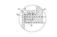
- FIG. 3 is a partially enlarged view showing a modification of FIG. 2 near the outer periphery of the piston in the cross-sectional view of FIG. 2.
- FIG. 3 is a partially enlarged view showing a modification of FIG. 2 near the outer periphery of the piston in the cross-sectional view of FIG. 2.
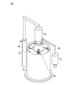
- (Viscous material supply device) 1 to 6 are views for explaining a viscous material supply apparatus according to an embodiment of the present invention.
- the viscous material supply device 100 is for discharging and supplying a viscous material.
- Viscous material supply device 100 uses grease, adhesives, liquid gaskets such as FIPG (on-site formed gasket), sealing agents, and other viscous materials as targets in the manufacturing process and maintenance of machines such as automobiles and industrial machines. Apply.
- FIPG on-site formed gasket
- the viscous material is a viscous material having fluidity but relatively low viscosity and relatively low flow resistance with respect to the pipe line and the nozzle.
- a viscous material having fluidity but relatively low viscosity and relatively low flow resistance with respect to the pipe line and the nozzle.
- grease for example, grease, adhesives, liquid gaskets such as FIPG, sealing agents, etc. including.
- a preferable viscosity of the viscous material is 200 Pa ⁇ s or less.
- a silicone gasket that is moisture-cured by a condensation reaction in the atmosphere is used as an example of a viscous material.
- the present invention is not limited to this.
- the viscous material supply device 100 includes a tank 10, a piston 20, a cover sheet 30, a seal member 40, a pump 50, an air cylinder 60, and a dispenser 70.
- a conduit 80 and an air vent valve 90 Details will be described below.
- the tank 10 has a storage space 11 for storing a viscous material.
- the tank 10 is a plastic or metal member such as polyethylene, polypropylene, ethylene vinyl acetate copolymer, polyethylene terephthalate, polyamide, etc. formed in a cylindrical shape, and the upper part of the cylindrical shape is opened so that a viscous material can be accommodated.
- the shape is not limited to a cylinder, and the shape may be a polygonal column shape such as a square column or a hexagonal column other than the above. Further, the shape of the tank 10 may not be a cylinder or a polygonal column as long as it can be stably installed on the ground.
- the viscous material is directly stored in the tank 10 without a bag or the like.
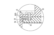
- the piston 20 is slidably inserted into the tank 10. As shown in FIG. 2, the piston 20 includes a main body portion 21, a pressing surface 22, a suction passage 23, a pin 24, a first outer shape portion 25, a second outer shape portion 26, and a nut 27.
- the main body 21 has a plate member 21a and a plate member 21b as shown in FIG.
- the plate member 21a is configured by a combination of a small diameter cylinder and a large diameter cylinder.
- the plate member 21b has different dimensions, the plate member 21b is configured by combining a small-diameter cylinder and a large-diameter cylinder in the same manner as the plate member 21a.
- the plate member 21a and the plate member 21b are integrally formed by a pin 24 and a nut 27.
- the specific shape of the main body 21 is not limited to the above as long as it can be slidably inserted into the tank 10 and can press the viscous material stored in the tank 10.
- the first outer portion 25 is a small-diameter cylindrical portion of the plate member 21b as shown in FIG. 2 and has an outer diameter (outer shape) smaller than that of the second outer portion 26.
- the second outer portion 26 is a large-diameter cylindrical portion of the plate member 21b, and is spaced apart from the first outer portion 25 in the downward direction in FIG. Is made up largely.
- a disc-shaped seal member 40 is attached to the outer periphery of the first outer shape portion 25.
- the large-diameter cylindrical portion of the plate member 21a and the second outer shape portion 26 of the plate member 21b have substantially the same outer diameter as shown in FIG. 2, but are not limited thereto.
- the pressing surface 22 is a part that presses the viscous material in the piston 20. As shown in FIG. 2, the pressing surface 22 corresponds to an end surface in the axial direction of the second outer shape portion 26 in the plate member 21 b of the main body portion 21.
- the pressing surface 22 is a portion that extends from the outer periphery of the second outer shape portion 26 of the plate member 21b to the outer periphery of the suction passage 23 in the radial direction, and has a substantially disk shape.
- the suction passage 23 is a portion through which the viscous material in the tank 10 circulates when pressed by the pressing surface 22. As shown in FIG. 2, the suction passage 23 is formed so as to cut out an axial center portion corresponding to the inner side in the radial direction of the main body portion 21.
- the suction passage 23 has a substantially circular cross-sectional shape in the present embodiment, but the cross-sectional shape is not limited to this as long as a viscous material can be circulated.
- a pipe 80 is connected to the piston 20, and the pipe 80 communicates with the suction passage 23. The viscous material stored in the storage space 11 of the tank 10 circulates in the suction passage 23 by being pressed by the pressing surface 22, and further flows from there to the pipe 80.
- the pin 24 is erected on the surface opposite to the pressing surface 22 in the axial direction of the piston 20, and attaches the covering sheet 30 to the piston 20.
- the pins 24 are erected at equal angular intervals at four positions every 90 degrees in the circumferential direction (angular direction) when viewed in plan from the axial direction of the piston 20.
- the number of pins 24, attachment locations, and angular intervals are not limited to the above, and may not be evenly arranged in the angular direction (circumferential direction).
- the pin 24 is formed with a screwing portion and screwed with the nut 27.
- the covering sheet 30 includes a covering portion 31, a communication hole 32, and an insertion hole 33.
- the covering portion 31 covers the pressing surface 22 of the piston 20. More specifically, the covering portion 31 covers the pressing surface 22 corresponding to the axial end surface of the second outer shape portion 26 of the plate member 21b of the piston 20.
- the material of the covering sheet 30 is not particularly limited, and examples thereof include polyethylene and polypropylene.
- the communication hole 32 communicates with the suction passage 23 of the piston 20 when the covering sheet 30 is attached to the piston 20.
- the communication hole 32 is formed in a substantially circular shape like the suction passage 23.
- the insertion hole 33 is provided relatively outward in the radial direction of the covering sheet 30. As shown in FIGS. 4 and 5, the outer periphery of the covering sheet 30 is folded back to the opposite side of the pressing surface 22 from the state where the covering sheet 30 is disposed on the pressing surface 22 side. The insertion hole 33 is fitted into the pin 24 of the piston 20 at the portion where the covering sheet 30 is folded. Thereby, the suction passage 23 of the piston 20 and the axial center of the communication hole 32 of the covering sheet 30 coincide.
- the covering sheet 30 is formed in a substantially rectangular shape when viewed in plan, but the shape is not limited to this as long as the pressing surface 22 of the piston 20 can be covered.
- the sealing member 40 has a substantially circular cylindrical cross section, and is attached to the outer periphery of the first outer portion 25 of the plate member 21 b of the piston 20.
- the seal member 40 is attached at the above position to seal a portion between the piston 20 and the tank 10.
- the material of the seal member 40 is not particularly limited as long as the gap between the piston 20 and the tank 10 can be sealed, but NBR (nitrile butadiene rubber), acrylic rubber, chloroprene rubber, fluororubber, polyurethane, etc., depending on the viscous material Selected.
- the pump 50 is not particularly limited as long as the viscous material pushed out from the tank 10 can be pumped to the dispenser 70 and the like, and examples thereof include a gear pump, a plunger pump, a screw pump, and a piston pump.
- the air cylinder 60 is provided to drive the piston 20 from the opening of the tank 10 toward the bottom by air pressure.
- the dispenser 70 is composed of a known one including a syringe and a plunger that can move in the syringe.
- the pipe line 80 is provided from the piston 20 to the dispenser 70 via the pump 50, and the viscous material circulates.
- the cross-sectional shape of the pipe line 80 is formed in a hollow substantially disk shape, it is not limited to this.
- the air vent valve 90 switches between opening and closing of the storage space 11 of the tank 10 and the outside in a state where the piston 20 is inserted into the storage space 11 of the tank 10.
- FIG. 6 is a flowchart showing a viscous material supply method according to an embodiment of the present invention.
- the viscous material supply method includes the tank 10, the piston 20, the covering sheet 30, and the like (ST1, 2).
- the covering sheet 30 is attached to the piston 20 (ST3).
- the viscous material is pressed by the pressing surface 22 of the piston 20, and the viscous material is pumped into the suction passage 23 (ST4).
- the attachment method of the covering sheet 30 corresponds to ST2 and ST3 in FIG. 6, and includes preparation of the piston 20 and the covering sheet 30 and attachment of the covering sheet 30 to the piston 20. Details will be described below.
- the parts from the tank 10 to the air vent valve 90 necessary for supplying the viscous material are prepared (ST1, ST2). At this time, the tank 10 is filled with a viscous material in advance. Next, the seal member 40 is attached to the piston 20.
- the covering sheet 30 is arranged on the pressing surface 22 side of the piston 20. Then, as shown in FIG. 4, the inner periphery of the covering portion 31 is brought into contact with the pressing surface 22 of the piston 20, and the opposing portion on the outer periphery of the covering sheet 30 is based on the outer peripheral portion of the second outer shape portion 26 of the piston 20. Fold back to the opposite side of the pressing surface 22. Then, the insertion hole 33 of the covering sheet 30 is fitted into the pin 24 of the piston 20.
- the folded portions f1 and f2 are formed as shown in FIG.
- the insertion hole 33 of the covering sheet 30 is fitted into the pin 24 of the piston 20.
- the suction passage 23 of the piston 20 and the communication hole 32 of the covering sheet 30 communicate with each other, and the shaft cores coincide.
- “coincidence” between the suction passage 23 and the communication hole 32 allows a displacement of about 2 to 3 mm.
- the piston 20 and the covering sheet 30 can be inserted into the tank 10 in this state. Further, in this state, the folded portion f ⁇ b> 2 of the covering sheet 30 is located outward of the seal member 40 in the radial direction. In other words, the seal member 40 comes into contact with the tank 10 through the covering sheet 30.
- the covering sheet 30 can be attached to the tank 10 in a state in which the folded portions f1 and f2 are formed, the following operation may be performed following FIG. That is, as shown in FIG. 5 subsequent to FIG. 4, a portion that has not yet been folded back on the outer periphery of the covering sheet 30 is folded back to the opposite side of the pressing surface 22 with the outer peripheral edge of the second outer shape portion 26 of the piston 20 as a base point. Then, the insertion hole 33 of the covering sheet 30 that is not fitted in FIG. 4 may be fitted into the pin 24 of the piston 20. As a result, folded portions f3 and f4 are formed.
- the piston 20 When the covering sheet 30 can be attached to the piston 20, the piston 20, the air cylinder 60, the pump 50, and the dispenser 70 are connected. Then, the piston 20 is driven by the air cylinder 60, pushed into the storage space 11 of the tank 10, and the pump 50 is operated, whereby the viscous material is circulated through the suction passage 23 and the conduit 80 and supplied from the dispenser 70 ( ST4).
- the operation of the pump 50 and the air cylinder 60 is stopped, and the supply of the viscous material is stopped (ST6).
- the piston 20 is extracted from the tank 10 (ST7).
- the pump 50 and the piston 20 are separated, and the covering sheet 30 is removed from the piston 20. Since the viscous material adheres to the suction passage 23 of the piston 20, it is cleaned (ST8). Since the pressing surface 22 of the piston 20 is covered with the covering portion 31 of the covering sheet 30, there is no need for cleaning, and the cleaning operation is facilitated accordingly.
- the tank 10 is replaced with a new one containing a viscous material (ST9).
- the covering sheet 30 is replaced with a new one (ST2). Then, the attachment of the covering sheet 30 to the piston 20 (ST3) and the viscous material pressure feeding (ST4) are repeated.
- the viscous material supply device 100 includes the tank 10, the piston 20, and the covering sheet 30.
- the tank 10 is provided with a storage space 11 for storing the viscous material.
- the piston 20 is slidably inserted into the tank 10, and is provided with a pressing surface 22 that presses the viscous material and a suction passage 23 through which the viscous material in the tank 10 flows by being pressed by the pressing surface 22.
- the covering sheet 30 includes a covering portion 31 that covers the pressing surface 22 of the piston 20 and a communication hole 32 that communicates with the suction passage 23.
- the viscous material supply method prepares the tank 10, the piston 20, and the covering sheet 30.
- the covering sheet 30 is attached to the piston 20 so that the covering portion 31 of the covering sheet 30 covers the pressing surface 22 of the piston 20 and the communication hole 32 of the covering sheet 30 communicates with the suction passage 23 of the piston 20.
- the viscous material is pressed by the pressing surface 22 of the piston 20, and the viscous material is circulated through the suction passage 23.
- the covering sheet 30 is attached to the piston 20 so that the covering portion 31 of the covering sheet 30 covers the pressing surface 22 of the piston 20 and the communication hole 32 of the covering sheet 30 communicates with the suction passage 23 of the piston 20.
- the pressing surface 22 of the piston 20 is covered with the covering portion 31 of the covering sheet 30, so that the viscous material can be prevented from adhering to the pressing surface 22. Can do.
- a pin 24 for attaching the covering sheet 30 to the piston 20 is provided upright on the piston 20 on the side opposite to the pressing surface 22.
- the covering sheet 30 includes an insertion hole 33 into which the pin 24 is fitted into the folded portion when the outside of the covering portion 31 is folded back to the side opposite to the pressing surface 22.
- the covering sheet 30 is disposed on the pressing surface 22 side of the piston 20, and the inner side (inner side) of the covering sheet 30 is brought into contact with the pressing surface 22 of the piston 20.
- the outer side (outer side) of the covering portion 31 is folded back to the side opposite to the pressing surface 22 side of the piston 20, and the insertion hole 33 is fitted into the pin 24 of the piston 20. In this manner, the insertion hole 33 is fitted into the pin 24 of the piston 20, so that the suction passage 23 and the axial center of the communication hole 32 of the covering sheet 30 coincide with each other.
- FIG. 7 is a cross-sectional view according to a comparative example similar to FIG.
- the piston 20 when the piston 20 is not provided with the pin 24 and the cover sheet S has no insertion hole and the positions of the suction passage and the communication hole are aligned, the operator visually observes the suction passage.
- the shaft core CL1 and the communication hole shaft CL2 must be aligned.
- the viscous material supply device 100 according to the present embodiment is configured as described above, the alignment of the suction passage 23 and the communication hole 32 can be simplified. Further, the alignment accuracy can be improved as compared with visual observation.
- the suction passage 23 is at least partially covered by the covering sheet 30, thereby preventing the viscous material from being pumped and the storage space of the tank 10. There is a possibility that a viscous material may remain on 11.
- the above situation is prevented and the viscous material remains in the storage space 11. It can be suppressed or reduced.
- a seal member 40 that seals a portion between the piston 20 and the tank 10 is attached to the outer periphery of the first outer portion 25 of the piston 20.
- the seal member 40 is attached to the outside of the first outer portion 25 in the radial direction of the piston 20 before the viscous material is sucked into the suction passage 23 by the pressing surface 22 of the piston 20. Therefore, the viscous material can be prevented from leaking from the outer periphery of the piston 20 when the viscous material in the tank 10 is pressed by the piston 20.
- FIG. 8 is a partially enlarged view showing a modification of FIG.
- a reinforcing member 34 for increasing the thickness of the edge of the insertion hole 33 may be provided at the edge of the insertion hole 33 in the covering sheet 30 as shown in FIG.
- the reinforcing member 34 is configured to be integrated with the covering sheet 30 by applying an adhesive material on the side facing (contacting) the covering sheet 30.
- the sealing member 40 demonstrated the embodiment which contacts the tank 10 via the coating sheet 30 in the above, it is not limited to this.
- the seal member 40 has the outer surface 41 positioned outward in the radial direction (radial direction) with respect to the covering sheet 30 attached to the piston 20 in the first outer shape portion 25. May be. In this case, when the seal member 40 is attached to the piston 20, the outer surface 41 of the seal member 40 is positioned outward in the radial direction with respect to the covering sheet 30 in the first outer shape portion 25.
- the covering sheet 30 is attached to the piston 20 before the sealing member 40 is attached to the piston 20. That is, the covering sheet 30 is disposed on the pressing surface 22 side, the inner periphery of the covering portion 31 is brought into contact with the pressing surface 22, and the outer periphery of the covering portion 31 is based on the outer peripheral edge portion of the second outer shape portion 26 of the piston 20. Is folded back to the opposite side of the pressing surface 22. Then, the insertion hole 33 is fitted into the pin 24. Thereby, the suction passage 23 and the axial center of the communication hole 32 coincide. The seal member 40 is then attached to the piston 20.
- the seal member 40 is positioned on the outer periphery of the covering sheet 30 in the first outer shape portion 25 and comes into contact with the tank 10 without passing through the covering sheet 30. Therefore, the space between the piston 20 and the tank 10 can be sealed more firmly.
- the storage space 11 of the tank 10 is directly filled with a viscous material.
- the present invention is not limited to this.
- not only the viscous material but also a bag for accommodating the viscous material may be accommodated in the storage space 11 of the tank 10.
- 10 tanks 100 viscous material supply device, 20 pistons, 22 pressing surface, 23 Suction passage, 24 pins, 25 first outer shape part, 26 second outer shape part, 30 coating sheet, 31 covering part, 32 communication holes, 33 Insertion hole, 34 reinforcement members, 40 sealing member, 41 outer surface, 50 pumps.
Landscapes
- Engineering & Computer Science (AREA)
- Mechanical Engineering (AREA)
- General Engineering & Computer Science (AREA)
- Coating Apparatus (AREA)
- Details Of Reciprocating Pumps (AREA)
- Reciprocating Pumps (AREA)
Abstract
Description
図1~図6は本発明の一実施形態に係る粘性材料供給装置の説明に供する図である。
タンク10は、図2に示すように粘性材料を貯留する貯留空間11を有する。タンク10は、円筒状に形成されたポリエチレン、ポリプロピレン、エチレン酢酸ビニル共重合体、ポリエチレンテレフタレート、ポリアミド等のプラスチック製又は金属製の部材であり、粘性材料を収容できるように円筒形状の上部を開口して構成している。しかし、タンク10は粘性材料を貯留できれば形状は円筒に限定されず、形状は上記以外にも例えば四角柱や六角柱等の多角柱形状で構成してもよい。また、タンク10は地面に安定して設置できれば、形状は円柱や多角柱でなくてもよい。本実施形態において粘性材料は、タンク10に袋等を介さずに直接的に収容されている。
ピストン20は、タンク10の内部に摺動可能に挿入される。ピストン20は、図2に示すように本体部21と、押圧面22と、吸い込み通路23と、ピン24と、第1外形部25と、第2外形部26と、ナット27と、を有する。
被覆シート30は、図2、図3に示すように被覆部31と、連通孔32と、挿通孔33と、を有する。
シール部材40は、断面が略円板の円筒形状に構成され、ピストン20のプレート部材21bの第1外形部25の外周に取り付けられる。シール部材40は、上記位置に取り付けられることによって、ピストン20とタンク10との間の部位をシールする。シール部材40の材料は、ピストン20とタンク10との間をシールできれば特に限定されないが、NBR(ニトリルブタジエンゴム)やアクリルゴム、クロロプレンゴム、フッ素ゴム、ポリウレタン等であって、粘性材料に応じて選択される。
ポンプ50は、タンク10から押し出された粘性材料をディスペンサ70等へ圧送できれば特に限定されず、例えばギヤポンプ、プランジャポンプ、スクリューポンプ、ピストンポンプ等を挙げることができる。
次に粘性材料供給方法及び被覆シート30の取り付け方法について説明する。図6は本発明の一実施形態に係る粘性材料供給方法について示すフローチャートである。粘性材料供給方法は、概説すれば、まずタンク10、ピストン20及び被覆シート30等を用意する(ST1、2)。次に、被覆シート30をピストン20へ取り付ける(ST3)。次に、ピストン20の押圧面22により粘性材料を押圧し、吸い込み通路23に粘性材料を圧送する(ST4)。また、被覆シート30の取り付け方法は、図6のST2、ST3にあたり、ピストン20及び被覆シート30の用意と、ピストン20への被覆シート30の取り付けと、を有する。以下、詳述する。
100 粘性材料供給装置、
20 ピストン、
22 押圧面、
23 吸い込み通路、
24 ピン、
25 第1外形部、
26 第2外形部、
30 被覆シート、
31 被覆部、
32 連通孔、
33 挿通孔、
34 補強部材、
40 シール部材、
41 外側面、
50 ポンプ。
Claims (13)
- 粘性材料を貯留する貯留空間が設けられたタンクと、
前記タンク内に摺動可能に挿入され、前記粘性材料を押圧する押圧面及び前記押圧面による押圧によって前記タンク内の前記粘性材料が流通する吸い込み通路が設けられたピストンと、
前記ピストンにおける前記押圧面を被覆する被覆部及び前記吸い込み通路に連通する連通孔を備えた被覆シートと、を有する粘性材料供給装置。 - 前記ピストンにおける前記押圧面と逆側に立設され、前記被覆シートを前記ピストンに取付けるピンをさらに有し、
前記被覆シートは、外周が前記押圧面と逆側に折り返され、折り返された部位において前記ピストンの前記ピンに嵌め込まれる挿通孔を備え、前記挿通孔を前記ピストンの前記ピンに嵌め込むことによって前記吸い込み通路と前記被覆シートの前記連通孔の軸芯を一致させる、請求項1に記載の粘性材料供給装置。 - 前記挿通孔には、前記挿通孔の縁部の厚さを増加させる補強部材が設けられる、請求項2に記載の粘性材料供給装置。
- 前記ピストンの外周に取り付けられ、前記ピストンと前記タンクとの間をシールするシール部材をさらに有する請求項1~3のいずれか1項に記載の粘性材料供給装置。
- 前記ピストンは、前記シール部材が取り付けられる第1外形部と、前記ピストンが摺動する方向において前記第1外形部から離間し前記第1外形部よりも外周が大きく形成された第2外形部と、をさらに備え、
前記シール部材は、外側面が少なくとも前記第1外形部において、前記ピストンに取り付けられた前記被覆シートよりも放射方向における外方に位置する、請求項4に記載の粘性材料供給装置。 - 請求項1~5のいずれか1項に記載の前記粘性材料供給装置に用いられ、前記ピストンにおける前記押圧面を被覆する被覆部及び前記吸い込み通路に連通する連通孔を備えた被覆シート。
- 前記ピストンにおいて前記押圧面と逆側に立設されたピンに嵌め込まれ、前記ピンに嵌め込まれることによって前記吸い込み通路と前記被覆シートの前記連通孔の軸芯を一致させる挿通孔をさらに備える、請求項6に記載の被覆シート。
- 粘性材料を貯留する貯留空間が設けられたタンクと、前記タンク内に摺動可能に挿入され、前記粘性材料を押圧する押圧面及び前記押圧面による押圧によって前記タンク内の前記粘性材料が流通する吸い込み通路が設けられたピストンと、前記ピストンにおける前記押圧面を被覆する被覆部及び前記吸い込み通路に連通する連通孔を備えた被覆シートと、を用意し、
前記被覆シートの前記被覆部が前記ピストンの前記押圧面を被覆し、かつ、前記被覆シートの前記連通孔が前記ピストンの前記吸い込み通路と連通するように前記被覆シートを前記ピストンに取り付け、
前記ピストンの前記押圧面によって前記粘性材料を押圧し、前記吸い込み通路に前記粘性材料を流通させる粘性材料供給方法。 - 前記ピストンにおける前記押圧面と逆側にはピンが立設されるとともに、前記被覆シートの前記被覆部には挿通孔が設けられ、
前記被覆シートを前記ピストンに取り付ける際には、前記被覆シートを前記ピストンの前記押圧面の側に配置し、前記被覆シートの前記被覆部における内方を前記ピストンの前記押圧面に当接させ、前記被覆シートの前記被覆部の外方を前記ピストンの前記押圧面と逆側に折り返し、前記被覆シートの前記挿通孔を前記ピストンの前記ピンに嵌め込む、請求項8に記載の粘性材料供給方法。 - 前記ピストンの前記押圧面によって前記粘性材料を前記吸い込み通路に流通させるよりも前に、前記ピストンの放射方向における外方において前記ピストンと前記タンクとの間をシールするシール部材を前記ピストンに取り付ける、請求項8又は9に記載の粘性材料供給方法。
- 前記ピストンには、前記シール部材を取り付ける第1外形部と、前記ピストンが摺動する方向において前記第1外形部から離間し前記第1外形部よりも外周が大きく形成された第2外形部と、が設けられ、
前記シール部材を前記ピストンに取り付ける際には、少なくとも前記第1外形部において前記シール部材の外側面を前記被覆シートよりも放射方向における外方に位置させる、請求項10に記載の粘性材料供給方法。 - 請求項8に記載の前記押圧面及び前記吸い込み通路が設けられた前記ピストンと、前記被覆部及び前記連通孔を備えた前記被覆シートと、を用意し、
前記被覆シートの前記被覆部が前記ピストンの前記押圧面を被覆し、かつ、前記被覆シートの前記連通孔が前記ピストンの前記吸い込み通路と連通するように前記被覆シートを前記ピストンに取り付ける、被覆シートの取り付け方法。 - 前記ピストンにおける前記押圧面と逆側にはピンが立設されるとともに、前記被覆シートの前記被覆部には挿通孔が設けられ、
前記被覆シートを前記ピストンに取り付ける際には、前記被覆シートを前記ピストンの前記押圧面の側に配置し、前記被覆シートの前記被覆部における内方を前記ピストンの前記押圧面に当接させ、前記被覆シートの前記被覆部の外方を前記ピストンの前記押圧面と逆側に折り返し、前記被覆シートの前記挿通孔を前記ピストンの前記ピンに嵌め込む、請求項12に記載の被覆シートの取り付け方法。
Priority Applications (5)
| Application Number | Priority Date | Filing Date | Title |
|---|---|---|---|
| CN201780085664.4A CN110267745B (zh) | 2017-02-28 | 2017-11-30 | 粘性材料供给装置及供给方法、包覆片及其安装方法 |
| KR1020197022960A KR102350299B1 (ko) | 2017-02-28 | 2017-11-30 | 점성재료 공급장치, 점성재료 공급장치에 사용되는 피복 시트, 점성재료 공급방법 및 피복 시트의 장착방법 |
| US16/485,534 US11480164B2 (en) | 2017-02-28 | 2017-11-30 | Viscous material supply device, cover sheet used in viscous material supply device, viscous material supply method, and method for attaching cover sheet |
| JP2019502460A JP6974763B2 (ja) | 2017-02-28 | 2017-11-30 | 粘性材料供給装置、粘性材料供給装置に用いられる被覆シート、粘性材料供給方法及び被覆シートの取り付け方法 |
| EP17898451.4A EP3590609A4 (en) | 2017-02-28 | 2017-11-30 | VISCOSE MATERIAL FEEDER, COVER FILM USED IN VISCOSE MATERIAL FEEDER, VISCOSE MATERIAL FEEDER METHOD AND METHOD FOR APPLYING A COVER FILM |
Applications Claiming Priority (2)
| Application Number | Priority Date | Filing Date | Title |
|---|---|---|---|
| JP2017037247 | 2017-02-28 | ||
| JP2017-037247 | 2017-02-28 |
Publications (1)
| Publication Number | Publication Date |
|---|---|
| WO2018159043A1 true WO2018159043A1 (ja) | 2018-09-07 |
Family
ID=63370802
Family Applications (1)
| Application Number | Title | Priority Date | Filing Date |
|---|---|---|---|
| PCT/JP2017/042942 WO2018159043A1 (ja) | 2017-02-28 | 2017-11-30 | 粘性材料供給装置、粘性材料供給装置に用いられる被覆シート、粘性材料供給方法及び被覆シートの取り付け方法 |
Country Status (6)
| Country | Link |
|---|---|
| US (1) | US11480164B2 (ja) |
| EP (1) | EP3590609A4 (ja) |
| JP (1) | JP6974763B2 (ja) |
| KR (1) | KR102350299B1 (ja) |
| CN (1) | CN110267745B (ja) |
| WO (1) | WO2018159043A1 (ja) |
Families Citing this family (3)
| Publication number | Priority date | Publication date | Assignee | Title |
|---|---|---|---|---|
| DE102017100712A1 (de) * | 2017-01-16 | 2018-07-19 | Atlas Copco Ias Gmbh | Vorrichtung und Verfahren zum Fördern von viskosem Material |
| EP3507236B1 (de) | 2016-09-05 | 2020-10-14 | Atlas Copco IAS GmbH | Fasspumpe mit anpassbarem dichtring der folgeplatte |
| DE102020127440A1 (de) * | 2020-08-06 | 2022-02-10 | Atlas Copco Ias Gmbh | Vorrichtung zum Fördern von viskosem Material |
Citations (7)
| Publication number | Priority date | Publication date | Assignee | Title |
|---|---|---|---|---|
| JPS6167873U (ja) * | 1984-10-06 | 1986-05-09 | ||
| JPS6456877U (ja) * | 1987-08-28 | 1989-04-10 | ||
| JPH0359070U (ja) * | 1989-10-11 | 1991-06-10 | ||
| JP2001301828A (ja) * | 2000-04-26 | 2001-10-31 | Honda Motor Co Ltd | 湿気硬化型シール剤の充填包装構造 |
| WO2011148735A1 (ja) * | 2010-05-24 | 2011-12-01 | 株式会社スリーボンド | 材料圧送装置 |
| WO2014097718A1 (ja) * | 2012-12-21 | 2014-06-26 | 株式会社スリーボンド | 粘性材料供給装置 |
| JP2017037247A (ja) | 2015-08-12 | 2017-02-16 | キヤノン株式会社 | 画像形成装置 |
Family Cites Families (15)
| Publication number | Priority date | Publication date | Assignee | Title |
|---|---|---|---|---|
| US1341652A (en) * | 1918-06-21 | 1920-06-01 | Frederick K Lawrence | Grease-cup filler |
| US1689360A (en) * | 1926-07-20 | 1928-10-30 | Monnot Robert | Grease-gun-filling device |
| US2768661A (en) * | 1953-03-27 | 1956-10-30 | Floyd W Tyler | Filling device for grease guns |
| US2811991A (en) * | 1954-06-07 | 1957-11-05 | Switzer Murt | Grease gun charging machines |
| KR890005050Y1 (ko) * | 1985-10-07 | 1989-07-31 | 가부시기가이샤 스리본드 | 점성유체 압송장치의 재료공급장치 |
| DE3904606A1 (de) * | 1989-02-16 | 1990-08-30 | Knieriem Guenther Dipl Ing Fh | Entleervorrichtung |
| US5117998A (en) * | 1991-10-07 | 1992-06-02 | Graco Inc. | Universal five gallon wiper plate assembly |
| FR2750961B1 (fr) * | 1996-07-15 | 1998-09-18 | Aubert Guy | Tete de piston aseptique et interchangeable |
| JP4035742B2 (ja) | 1997-11-27 | 2008-01-23 | ノードソン株式会社 | 粘性材料の汲み出し輸送方法及び装置 |
| US6644179B1 (en) * | 2003-03-22 | 2003-11-11 | Rutherford Kiehm | Measured utility kitchen tool |
| DE102004016006A1 (de) | 2004-04-01 | 2005-09-29 | Robert Bosch Gmbh | Gebinde und dafür vorgesehenes Gebindeentleerungssystem |
| JP4670302B2 (ja) | 2004-10-06 | 2011-04-13 | 株式会社スリーボンド | 材料圧送装置 |
| DE102005049805B4 (de) | 2005-08-19 | 2007-06-14 | Erich Scheugenpflug | Entleervorrichtung |
| US7946454B2 (en) * | 2006-12-21 | 2011-05-24 | Paul Scardino | System and method for dispensing of viscous food product |
| DE102007003972B4 (de) | 2007-01-26 | 2012-01-19 | Viscotec Pumpen- Und Dosiertechnik Gmbh | Vorrichtung zur luftfreien Entnahme und verbesserten Entlüftung mit porösen Trennplatten |
-
2017
- 2017-11-30 EP EP17898451.4A patent/EP3590609A4/en active Pending
- 2017-11-30 WO PCT/JP2017/042942 patent/WO2018159043A1/ja unknown
- 2017-11-30 CN CN201780085664.4A patent/CN110267745B/zh active Active
- 2017-11-30 US US16/485,534 patent/US11480164B2/en active Active
- 2017-11-30 KR KR1020197022960A patent/KR102350299B1/ko active IP Right Grant
- 2017-11-30 JP JP2019502460A patent/JP6974763B2/ja active Active
Patent Citations (7)
| Publication number | Priority date | Publication date | Assignee | Title |
|---|---|---|---|---|
| JPS6167873U (ja) * | 1984-10-06 | 1986-05-09 | ||
| JPS6456877U (ja) * | 1987-08-28 | 1989-04-10 | ||
| JPH0359070U (ja) * | 1989-10-11 | 1991-06-10 | ||
| JP2001301828A (ja) * | 2000-04-26 | 2001-10-31 | Honda Motor Co Ltd | 湿気硬化型シール剤の充填包装構造 |
| WO2011148735A1 (ja) * | 2010-05-24 | 2011-12-01 | 株式会社スリーボンド | 材料圧送装置 |
| WO2014097718A1 (ja) * | 2012-12-21 | 2014-06-26 | 株式会社スリーボンド | 粘性材料供給装置 |
| JP2017037247A (ja) | 2015-08-12 | 2017-02-16 | キヤノン株式会社 | 画像形成装置 |
Non-Patent Citations (1)
| Title |
|---|
| See also references of EP3590609A4 |
Also Published As
| Publication number | Publication date |
|---|---|
| CN110267745A (zh) | 2019-09-20 |
| EP3590609A4 (en) | 2020-03-04 |
| CN110267745B (zh) | 2022-02-15 |
| JP6974763B2 (ja) | 2021-12-01 |
| KR20190122661A (ko) | 2019-10-30 |
| KR102350299B1 (ko) | 2022-01-11 |
| US11480164B2 (en) | 2022-10-25 |
| US20200018299A1 (en) | 2020-01-16 |
| EP3590609A1 (en) | 2020-01-08 |
| JPWO2018159043A1 (ja) | 2019-12-26 |
Similar Documents
| Publication | Publication Date | Title |
|---|---|---|
| WO2018159043A1 (ja) | 粘性材料供給装置、粘性材料供給装置に用いられる被覆シート、粘性材料供給方法及び被覆シートの取り付け方法 | |
| US9309042B2 (en) | Liquid dispensing syringe and method for reducing piston bounce | |
| WO2014097718A1 (ja) | 粘性材料供給装置 | |
| AU2015312253B2 (en) | Cartridge | |
| US7621375B2 (en) | Pneumatic grease applicator | |
| JP3552431B2 (ja) | 材料塗布装置 | |
| JP2007283214A (ja) | 塗布剤の塗布方法とその塗布装置 | |
| CN107442315B (zh) | 粘性液体排出设备 | |
| WO2021131327A1 (ja) | 材料塗布装置及び押圧部材 | |
| KR101617715B1 (ko) | 구리스 자동 도포장치의 구리스 주입기 | |
| GB2457083A (en) | Lubricating system with oil container | |
| JP7094906B2 (ja) | 流動性材料吐出装置 | |
| JP4538524B2 (ja) | 静電塗装装置の中間貯留槽 | |
| JP4062695B2 (ja) | 流体圧送ポンプのフォロープレートの容器挿抜方法およびそのためのフォロープレート | |
| JP2750665B2 (ja) | 2液混合硬化性樹脂の注入機及び注入ミキサーノズル | |
| JP3175857U (ja) | ディスペンサー装置 | |
| JP2007085472A (ja) | 潤滑ポンプ装置 | |
| US20210394225A1 (en) | Assembly, method for using assembly, applying device, method for using applying device, method for replenishing material | |
| JP2002061585A (ja) | 揮発性成分を含む液体の圧送装置のシール構造 | |
| JPH056453Y2 (ja) | ||
| JPH04362280A (ja) | 高粘度ポンプ装置 | |
| JPH03246380A (ja) | 高粘度ポンプ | |
| Cocco | Chemical Gaskets | |
| JPH06280739A (ja) | 多連式プランジャーポンプによる液体圧送方法とそのポンプ | |
| JPH0486382A (ja) | 高粘度材用ポンプ装置 |
Legal Events
| Date | Code | Title | Description |
|---|---|---|---|
| 121 | Ep: the epo has been informed by wipo that ep was designated in this application |
Ref document number: 17898451 Country of ref document: EP Kind code of ref document: A1 |
|
| ENP | Entry into the national phase |
Ref document number: 2019502460 Country of ref document: JP Kind code of ref document: A |
|
| ENP | Entry into the national phase |
Ref document number: 20197022960 Country of ref document: KR Kind code of ref document: A |
|
| NENP | Non-entry into the national phase |
Ref country code: DE |
|
| ENP | Entry into the national phase |
Ref document number: 2017898451 Country of ref document: EP Effective date: 20190930 |