WO2018139306A1 - ディスクブレーキ - Google Patents
ディスクブレーキ Download PDFInfo
- Publication number
- WO2018139306A1 WO2018139306A1 PCT/JP2018/001192 JP2018001192W WO2018139306A1 WO 2018139306 A1 WO2018139306 A1 WO 2018139306A1 JP 2018001192 W JP2018001192 W JP 2018001192W WO 2018139306 A1 WO2018139306 A1 WO 2018139306A1
- Authority
- WO
- WIPO (PCT)
- Prior art keywords
- pin
- pair
- disk
- peripheral surface
- main body
- Prior art date
- Legal status (The legal status is an assumption and is not a legal conclusion. Google has not performed a legal analysis and makes no representation as to the accuracy of the status listed.)
- Ceased
Links
Images




Classifications
-
- F—MECHANICAL ENGINEERING; LIGHTING; HEATING; WEAPONS; BLASTING
- F16—ENGINEERING ELEMENTS AND UNITS; GENERAL MEASURES FOR PRODUCING AND MAINTAINING EFFECTIVE FUNCTIONING OF MACHINES OR INSTALLATIONS; THERMAL INSULATION IN GENERAL
- F16D—COUPLINGS FOR TRANSMITTING ROTATION; CLUTCHES; BRAKES
- F16D55/00—Brakes with substantially-radial braking surfaces pressed together in axial direction, e.g. disc brakes
- F16D55/02—Brakes with substantially-radial braking surfaces pressed together in axial direction, e.g. disc brakes with axially-movable discs or pads pressed against axially-located rotating members
- F16D55/22—Brakes with substantially-radial braking surfaces pressed together in axial direction, e.g. disc brakes with axially-movable discs or pads pressed against axially-located rotating members by clamping an axially-located rotating disc between movable braking members, e.g. movable brake discs or brake pads
- F16D55/224—Brakes with substantially-radial braking surfaces pressed together in axial direction, e.g. disc brakes with axially-movable discs or pads pressed against axially-located rotating members by clamping an axially-located rotating disc between movable braking members, e.g. movable brake discs or brake pads with a common actuating member for the braking members
- F16D55/225—Brakes with substantially-radial braking surfaces pressed together in axial direction, e.g. disc brakes with axially-movable discs or pads pressed against axially-located rotating members by clamping an axially-located rotating disc between movable braking members, e.g. movable brake discs or brake pads with a common actuating member for the braking members the braking members being brake pads
- F16D55/226—Brakes with substantially-radial braking surfaces pressed together in axial direction, e.g. disc brakes with axially-movable discs or pads pressed against axially-located rotating members by clamping an axially-located rotating disc between movable braking members, e.g. movable brake discs or brake pads with a common actuating member for the braking members the braking members being brake pads in which the common actuating member is moved axially, e.g. floating caliper disc brakes
- F16D55/2265—Brakes with substantially-radial braking surfaces pressed together in axial direction, e.g. disc brakes with axially-movable discs or pads pressed against axially-located rotating members by clamping an axially-located rotating disc between movable braking members, e.g. movable brake discs or brake pads with a common actuating member for the braking members the braking members being brake pads in which the common actuating member is moved axially, e.g. floating caliper disc brakes the axial movement being guided by one or more pins engaging bores in the brake support or the brake housing
- F16D55/227—Brakes with substantially-radial braking surfaces pressed together in axial direction, e.g. disc brakes with axially-movable discs or pads pressed against axially-located rotating members by clamping an axially-located rotating disc between movable braking members, e.g. movable brake discs or brake pads with a common actuating member for the braking members the braking members being brake pads in which the common actuating member is moved axially, e.g. floating caliper disc brakes the axial movement being guided by one or more pins engaging bores in the brake support or the brake housing by two or more pins
-
- F—MECHANICAL ENGINEERING; LIGHTING; HEATING; WEAPONS; BLASTING
- F16—ENGINEERING ELEMENTS AND UNITS; GENERAL MEASURES FOR PRODUCING AND MAINTAINING EFFECTIVE FUNCTIONING OF MACHINES OR INSTALLATIONS; THERMAL INSULATION IN GENERAL
- F16D—COUPLINGS FOR TRANSMITTING ROTATION; CLUTCHES; BRAKES
- F16D55/00—Brakes with substantially-radial braking surfaces pressed together in axial direction, e.g. disc brakes
- F16D55/02—Brakes with substantially-radial braking surfaces pressed together in axial direction, e.g. disc brakes with axially-movable discs or pads pressed against axially-located rotating members
- F16D55/22—Brakes with substantially-radial braking surfaces pressed together in axial direction, e.g. disc brakes with axially-movable discs or pads pressed against axially-located rotating members by clamping an axially-located rotating disc between movable braking members, e.g. movable brake discs or brake pads
- F16D55/224—Brakes with substantially-radial braking surfaces pressed together in axial direction, e.g. disc brakes with axially-movable discs or pads pressed against axially-located rotating members by clamping an axially-located rotating disc between movable braking members, e.g. movable brake discs or brake pads with a common actuating member for the braking members
- F16D55/225—Brakes with substantially-radial braking surfaces pressed together in axial direction, e.g. disc brakes with axially-movable discs or pads pressed against axially-located rotating members by clamping an axially-located rotating disc between movable braking members, e.g. movable brake discs or brake pads with a common actuating member for the braking members the braking members being brake pads
- F16D55/226—Brakes with substantially-radial braking surfaces pressed together in axial direction, e.g. disc brakes with axially-movable discs or pads pressed against axially-located rotating members by clamping an axially-located rotating disc between movable braking members, e.g. movable brake discs or brake pads with a common actuating member for the braking members the braking members being brake pads in which the common actuating member is moved axially, e.g. floating caliper disc brakes
- F16D55/2265—Brakes with substantially-radial braking surfaces pressed together in axial direction, e.g. disc brakes with axially-movable discs or pads pressed against axially-located rotating members by clamping an axially-located rotating disc between movable braking members, e.g. movable brake discs or brake pads with a common actuating member for the braking members the braking members being brake pads in which the common actuating member is moved axially, e.g. floating caliper disc brakes the axial movement being guided by one or more pins engaging bores in the brake support or the brake housing
-
- F—MECHANICAL ENGINEERING; LIGHTING; HEATING; WEAPONS; BLASTING
- F16—ENGINEERING ELEMENTS AND UNITS; GENERAL MEASURES FOR PRODUCING AND MAINTAINING EFFECTIVE FUNCTIONING OF MACHINES OR INSTALLATIONS; THERMAL INSULATION IN GENERAL
- F16D—COUPLINGS FOR TRANSMITTING ROTATION; CLUTCHES; BRAKES
- F16D65/00—Parts or details
- F16D65/005—Components of axially engaging brakes not otherwise provided for
- F16D65/0087—Brake housing guide members, e.g. caliper pins; Accessories therefor, e.g. dust boots
-
- F—MECHANICAL ENGINEERING; LIGHTING; HEATING; WEAPONS; BLASTING
- F16—ENGINEERING ELEMENTS AND UNITS; GENERAL MEASURES FOR PRODUCING AND MAINTAINING EFFECTIVE FUNCTIONING OF MACHINES OR INSTALLATIONS; THERMAL INSULATION IN GENERAL
- F16D—COUPLINGS FOR TRANSMITTING ROTATION; CLUTCHES; BRAKES
- F16D55/00—Brakes with substantially-radial braking surfaces pressed together in axial direction, e.g. disc brakes
- F16D2055/0004—Parts or details of disc brakes
- F16D2055/0016—Brake calipers
-
- F—MECHANICAL ENGINEERING; LIGHTING; HEATING; WEAPONS; BLASTING
- F16—ENGINEERING ELEMENTS AND UNITS; GENERAL MEASURES FOR PRODUCING AND MAINTAINING EFFECTIVE FUNCTIONING OF MACHINES OR INSTALLATIONS; THERMAL INSULATION IN GENERAL
- F16D—COUPLINGS FOR TRANSMITTING ROTATION; CLUTCHES; BRAKES
- F16D55/00—Brakes with substantially-radial braking surfaces pressed together in axial direction, e.g. disc brakes
- F16D2055/0004—Parts or details of disc brakes
- F16D2055/007—Pins holding the braking members
-
- F—MECHANICAL ENGINEERING; LIGHTING; HEATING; WEAPONS; BLASTING
- F16—ENGINEERING ELEMENTS AND UNITS; GENERAL MEASURES FOR PRODUCING AND MAINTAINING EFFECTIVE FUNCTIONING OF MACHINES OR INSTALLATIONS; THERMAL INSULATION IN GENERAL
- F16D—COUPLINGS FOR TRANSMITTING ROTATION; CLUTCHES; BRAKES
- F16D2121/00—Type of actuator operation force
- F16D2121/02—Fluid pressure
- F16D2121/04—Fluid pressure acting on a piston-type actuator, e.g. for liquid pressure
-
- F—MECHANICAL ENGINEERING; LIGHTING; HEATING; WEAPONS; BLASTING
- F16—ENGINEERING ELEMENTS AND UNITS; GENERAL MEASURES FOR PRODUCING AND MAINTAINING EFFECTIVE FUNCTIONING OF MACHINES OR INSTALLATIONS; THERMAL INSULATION IN GENERAL
- F16D—COUPLINGS FOR TRANSMITTING ROTATION; CLUTCHES; BRAKES
- F16D2121/00—Type of actuator operation force
- F16D2121/14—Mechanical
-
- F—MECHANICAL ENGINEERING; LIGHTING; HEATING; WEAPONS; BLASTING
- F16—ENGINEERING ELEMENTS AND UNITS; GENERAL MEASURES FOR PRODUCING AND MAINTAINING EFFECTIVE FUNCTIONING OF MACHINES OR INSTALLATIONS; THERMAL INSULATION IN GENERAL
- F16D—COUPLINGS FOR TRANSMITTING ROTATION; CLUTCHES; BRAKES
- F16D2125/00—Components of actuators
- F16D2125/18—Mechanical mechanisms
- F16D2125/20—Mechanical mechanisms converting rotation to linear movement or vice versa
- F16D2125/22—Mechanical mechanisms converting rotation to linear movement or vice versa acting transversely to the axis of rotation
- F16D2125/28—Cams; Levers with cams
-
- F—MECHANICAL ENGINEERING; LIGHTING; HEATING; WEAPONS; BLASTING
- F16—ENGINEERING ELEMENTS AND UNITS; GENERAL MEASURES FOR PRODUCING AND MAINTAINING EFFECTIVE FUNCTIONING OF MACHINES OR INSTALLATIONS; THERMAL INSULATION IN GENERAL
- F16D—COUPLINGS FOR TRANSMITTING ROTATION; CLUTCHES; BRAKES
- F16D2125/00—Components of actuators
- F16D2125/18—Mechanical mechanisms
- F16D2125/58—Mechanical mechanisms transmitting linear movement
- F16D2125/582—Flexible element, e.g. spring, other than the main force generating element
-
- F—MECHANICAL ENGINEERING; LIGHTING; HEATING; WEAPONS; BLASTING
- F16—ENGINEERING ELEMENTS AND UNITS; GENERAL MEASURES FOR PRODUCING AND MAINTAINING EFFECTIVE FUNCTIONING OF MACHINES OR INSTALLATIONS; THERMAL INSULATION IN GENERAL
- F16D—COUPLINGS FOR TRANSMITTING ROTATION; CLUTCHES; BRAKES
- F16D55/00—Brakes with substantially-radial braking surfaces pressed together in axial direction, e.g. disc brakes
- F16D55/02—Brakes with substantially-radial braking surfaces pressed together in axial direction, e.g. disc brakes with axially-movable discs or pads pressed against axially-located rotating members
- F16D55/22—Brakes with substantially-radial braking surfaces pressed together in axial direction, e.g. disc brakes with axially-movable discs or pads pressed against axially-located rotating members by clamping an axially-located rotating disc between movable braking members, e.g. movable brake discs or brake pads
- F16D55/224—Brakes with substantially-radial braking surfaces pressed together in axial direction, e.g. disc brakes with axially-movable discs or pads pressed against axially-located rotating members by clamping an axially-located rotating disc between movable braking members, e.g. movable brake discs or brake pads with a common actuating member for the braking members
- F16D55/225—Brakes with substantially-radial braking surfaces pressed together in axial direction, e.g. disc brakes with axially-movable discs or pads pressed against axially-located rotating members by clamping an axially-located rotating disc between movable braking members, e.g. movable brake discs or brake pads with a common actuating member for the braking members the braking members being brake pads
- F16D55/226—Brakes with substantially-radial braking surfaces pressed together in axial direction, e.g. disc brakes with axially-movable discs or pads pressed against axially-located rotating members by clamping an axially-located rotating disc between movable braking members, e.g. movable brake discs or brake pads with a common actuating member for the braking members the braking members being brake pads in which the common actuating member is moved axially, e.g. floating caliper disc brakes
- F16D55/2265—Brakes with substantially-radial braking surfaces pressed together in axial direction, e.g. disc brakes with axially-movable discs or pads pressed against axially-located rotating members by clamping an axially-located rotating disc between movable braking members, e.g. movable brake discs or brake pads with a common actuating member for the braking members the braking members being brake pads in which the common actuating member is moved axially, e.g. floating caliper disc brakes the axial movement being guided by one or more pins engaging bores in the brake support or the brake housing
- F16D55/22655—Constructional details of guide pins
-
- F—MECHANICAL ENGINEERING; LIGHTING; HEATING; WEAPONS; BLASTING
- F16—ENGINEERING ELEMENTS AND UNITS; GENERAL MEASURES FOR PRODUCING AND MAINTAINING EFFECTIVE FUNCTIONING OF MACHINES OR INSTALLATIONS; THERMAL INSULATION IN GENERAL
- F16D—COUPLINGS FOR TRANSMITTING ROTATION; CLUTCHES; BRAKES
- F16D65/00—Parts or details
- F16D65/005—Components of axially engaging brakes not otherwise provided for
- F16D65/0068—Brake calipers
-
- F—MECHANICAL ENGINEERING; LIGHTING; HEATING; WEAPONS; BLASTING
- F16—ENGINEERING ELEMENTS AND UNITS; GENERAL MEASURES FOR PRODUCING AND MAINTAINING EFFECTIVE FUNCTIONING OF MACHINES OR INSTALLATIONS; THERMAL INSULATION IN GENERAL
- F16D—COUPLINGS FOR TRANSMITTING ROTATION; CLUTCHES; BRAKES
- F16D65/00—Parts or details
- F16D65/14—Actuating mechanisms for brakes; Means for initiating operation at a predetermined position
- F16D65/16—Actuating mechanisms for brakes; Means for initiating operation at a predetermined position arranged in or on the brake
- F16D65/18—Actuating mechanisms for brakes; Means for initiating operation at a predetermined position arranged in or on the brake adapted for drawing members together, e.g. for disc brakes
- F16D65/183—Actuating mechanisms for brakes; Means for initiating operation at a predetermined position arranged in or on the brake adapted for drawing members together, e.g. for disc brakes with force-transmitting members arranged side by side acting on a spot type force-applying member
-
- F—MECHANICAL ENGINEERING; LIGHTING; HEATING; WEAPONS; BLASTING
- F16—ENGINEERING ELEMENTS AND UNITS; GENERAL MEASURES FOR PRODUCING AND MAINTAINING EFFECTIVE FUNCTIONING OF MACHINES OR INSTALLATIONS; THERMAL INSULATION IN GENERAL
- F16F—SPRINGS; SHOCK-ABSORBERS; MEANS FOR DAMPING VIBRATION
- F16F1/00—Springs
- F16F1/36—Springs made of rubber or other material having high internal friction, e.g. thermoplastic elastomers
- F16F1/373—Springs made of rubber or other material having high internal friction, e.g. thermoplastic elastomers characterised by having a particular shape
- F16F1/376—Springs made of rubber or other material having high internal friction, e.g. thermoplastic elastomers characterised by having a particular shape having projections, studs, serrations or the like on at least one surface
Definitions
- the present invention relates to a disc brake for vehicle braking.
- This application claims priority on Japanese Patent Application No. 2017-012231 filed in Japan on January 26, 2017, the contents of which are incorporated herein by reference.
- a bush is provided in a pin hole of a support member into which a slide pin of a caliper is inserted (for example, refer to Patent Document 1).
- a bush is provided on the slide pin of the caliper (see, for example, Patent Document 2).
- JP 2008-89012 A Japanese Utility Model Publication No. 6-28366
- the present invention provides a disc brake capable of suppressing the generation of abnormal noise.
- one of the pair of slide pins includes a pin body having an annular groove on a tip end side, and a plurality of convex portions on an inner peripheral side.
- a cylindrical elastic deformation member provided on the surface.
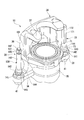
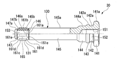
- the fragmentary perspective view which shows the caliper of the disc brake of embodiment. The side view which made the cross section the one side from the centerline which shows the slide pin of the disc brake of embodiment.
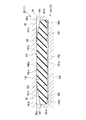
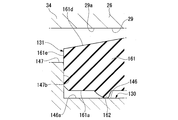
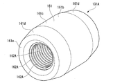
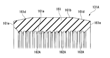
- the perspective view which shows the bush of the disc brake of embodiment. The expanded sectional view of the principal part which shows the pin support part and slide pin of the disc brake of embodiment.
- the disc brake 10 applies a braking force to the vehicle.
- the disc brake includes an attachment member 11, a pair of pads 12, a caliper 13, a parking brake wire 15, and a parking brake cable 16.
- the mounting member 11 is disposed so as to straddle the outer diameter side of the disc-like disc 20 that rotates together with a wheel (not shown) to be braked, and is fixed to a non-rotating portion of a vehicle (not shown).
- the pair of pads 12 are supported by the mounting member 11 so as to be slidable in the axial direction of the disk 20 in a state of being opposed to both surfaces of the disk 20.
- the caliper 13 is supported by the mounting member 11 so as to be slidable in the axial direction of the disk 20 while straddling the outer diameter side of the disk 20.
- the caliper 13 imparts frictional resistance to the disk 20 by pressing the pair of pads 12 in contact with both surfaces of the disk 20.
- the radial direction of the disk 20 is referred to as a disk radial direction
- the axial direction of the disk 20 is referred to as a disk axial direction
- the circumferential direction (rotation direction) of the disk 20 is referred to as a disk circumferential direction.
- the attachment member 11 includes a carrier 22 that is integrally formed by casting and is fixed to a non-rotating portion of a vehicle (not shown), and a pair of pad guides 23 that are formed by pressing from a plate material and are attached to the carrier 22. Yes.
- the carrier 22 supports an inner side of the pair of pads 12 movably in the disc axial direction via a pair of pad guides 23 on both sides in the disc circumferential direction of the pads 12 arranged on the inner side in the vehicle width direction.
- a pair of pin support portions 26 are disposed across the outer peripheral side of the disk 20.
- the carrier 22 has a pair of pin holes 29 extending from the inner side to the pair of pin support portions 26 on the outer side in the disk radial direction at both ends in the circumferential direction of the disk.
- a pair of slide pins 30 and 31 provided on both sides of the caliper 13 in the circumferential direction of the caliper 13 are slidably inserted from the inner side into the pair of pin holes 29 so as to be slidable in the disc axial direction. Yes. That is, one slide pin 30 is in one pin hole 29 formed in one pin support portion 26, and the other slide pin 31 is in the other pin hole 29 formed in the other pin support portion 26. Each is inserted.
- the caliper 13 having the pair of slide pins 30, 31 can move in the disc axial direction to the mounting member 11 having the pair of pin holes 29. It is supported by.
- the portions of the pair of slide pins 30 and 31 that protrude from the carrier 22 are covered with a pair of extendable boots 32.
- the caliper 13 has a pair of slide pins 30 and 31 attached to both ends in the circumferential direction of the disc, and a caliper body 34 supported by the attachment member 11 via the pair of slide pins 30 and 31 in a state of straddling the disc 20.
- the caliper body 34 includes a cylinder portion 35, a bridge portion 36, a claw portion 37, a pair of arm portions 38, a guide attachment portion 39, and a hose attachment portion 40, which are integrated by casting. Is formed.
- the caliper 13 has a caliper body 34 in which a cylinder portion 35 is disposed on the inner side which is one side in the axial direction of the disc 20, and a claw portion 37 is disposed on the outer side which is the other side in the axial direction of the disc 20.
- a bridge portion 36 connecting the cylinder 37 and the cylinder portion 35 is a so-called fist type caliper provided across the disk 20.
- the pair of slide pins 30 and 31 described above are fixed to the pair of arm portions 38 so as to protrude along the disk axial direction and toward the claw portion 37.
- the pair of slide pins 30 and 31 are fixed to the pair of arm portions 38 by a pair of bolts 41 screwed from the inner side.
- the cylinder part 35 of the caliper body 34 has a bottomed cylinder having a cylindrical cylinder cylinder part 50 and a cylinder bottom part 51 provided so as to close one end of the cylinder cylinder part 50 in the axial direction. It has a shape.
- the cylinder portion 35 of the caliper body 34 has its cylinder opening 52 opposed to the inner pad 12.
- the inner peripheral surface and the bottom surface of the cylinder tube portion 50 are referred to as a bore 55.
- the bore 55 is formed in the cylinder portion 35, and the cylinder bottom portion 51 is a bore bottom in the cylinder portion 35.
- the caliper body 34 is provided with an arrangement hole 56 having a circular cross section along the direction orthogonal to the axial direction of the cylinder portion 35 in the cylinder bottom portion 51.
- the cylinder bottom 51 is formed with a communication hole 57 penetrating from the center position of the bottom surface of the bore 55 to the arrangement hole 56 along the axial direction of the cylinder portion 35.
- a back position hole 58 is formed on the most cylinder bottom 51 side, and a back position hole 58 is located on the cylinder opening 52 side from the back position hole 58.
- a sliding hole 59 having a diameter larger than that of the hole 58 is formed.
- a piston seal 60 that seals between a piston 72 (described later) and a cylinder portion 35 is held in the vicinity of the end of the sliding hole 59 opposite to the back position hole 58.
- a recess-shaped axial groove 64 that is recessed in the radial direction and extending in the axial direction is formed on the inner peripheral surface of the back position hole 58 of the cylinder tube portion 50.
- the caliper 13 has a piston 72 formed in a covered cylinder shape having a cylindrical tube portion 70 and a disc-shaped cover portion 71.
- the piston 72 is accommodated in a bore 55 formed in the cylinder portion 35 of the caliper body 34 in a posture in which the cylinder portion 70 side is directed to the cylinder bottom portion 51 side.
- the moving hole 59 is slidably fitted.
- the caliper 13 covers the gap between the piston 72 and the bore 55 of the cylinder part 35 on the outside between the inner peripheral part on the cylinder opening 52 side of the cylinder part 35 and the outer peripheral part on the lid part 71 side of the piston 72.
- An elastic boot 73 is provided.
- a brake hose (not shown) is attached to the hose attachment portion 40 shown in FIG. Brake fluid from the brake hose is introduced into a chamber 206 between the cylinder portion 35 and the piston 72 shown in FIG. Due to the hydraulic pressure of the brake fluid introduced into the chamber 206, the piston 72 slidably fitted in the bore 55 is slid in the sliding hole 59 of the cylinder portion 35, and moves from the cylinder portion 35 toward the pad 12. Move. As the piston 72 moves, the caliper 13 slides with respect to the mounting member 11, and grips the pair of pads 12 from both sides by the piston 72 and the claw portion 37, thereby bringing these pads 12 into contact with the disk 20. . In other words, the pair of pads 12 movably supported by the mounting member 11 are pressed against both surfaces of the disk 20 by the caliper 13.
- the caliper 13 During normal braking by a depressing operation on a brake pedal (not shown), the caliper 13 introduces brake hydraulic pressure into a chamber 206 between the cylinder portion 35 and the piston 72 via a brake hose from a master cylinder (not shown). . Then, the piston 72 slides in the cylinder portion 35 with the introduced brake fluid pressure and protrudes from the cylinder portion 35 in the direction of the claw portion 37, thereby bringing the pair of pads 12 into contact with the disk 20 and controlling. Generate power.
- the caliper 13 is a parking brake that generates a braking force by pressing the pair of pads 12 against the disk 20 by mechanically propelling the piston 72 provided on the caliper body 34 instead of such a brake fluid pressure.
- a mechanism 81 is provided in the caliper body 34.
- the parking brake mechanism 81 is provided in the caliper body 34 to propel the piston 72. That is, the caliper 13 is a built-in caliper that incorporates the parking brake mechanism 81.
- the parking brake mechanism 81 has a cam mechanism 82 that is accommodated in the cylinder portion 35.
- the cam mechanism 82 has an arc-shaped bearing 83 fitted in the arrangement hole 56 of the caliper body 34, and is disposed in the arrangement hole 56.
- the cam mechanism 82 is substantially supported by the arrangement hole 56 via the bearing 83 so as to be rotatable.
- a cylindrical rotating member 84 is formed with a cam recess 85 that is recessed in a substantially V shape from the outer peripheral surface in the radial direction toward the center.
- the cam recess 85 is offset from the center axis of the rotating member 84 at the most recessed position.
- the cam mechanism 82 includes a cam rod 88 having one end inserted into the cam recess 85 and the other end disposed in the communication hole 57, and the cam rod 88 rotates around an axis along the axis orthogonal direction of the cylinder portion 35.
- the rotating member 84 is driven to rotate, the amount of protrusion from the rotating member 84 is changed depending on the shape of the cam recess 85. That is, since the bottom of the cam recess 85 is offset with respect to the center of the rotating member 84, the position of the bottom moves forward and backward with respect to the communication hole 57 when the rotating member 84 rotates, and comes into contact with the bottom. The amount of protrusion of the cam rod 88 toward the communication hole 57 is changed.
- the rotating member 84 arranged in the arrangement hole 56 partially protrudes outward from the cylinder bottom 51 of the caliper body 34, and a lever member 89 is formed on this protruding portion of the rotating member 84.
- the rotating member 84 is fixed to the lever member 89, and rotates together with the lever member 89 when the lever member 89 is driven to rotate.
- a stopper member 211 that abuts against the abutting portion 210 of the lever member 89 and restricts further rotation of the lever member 89 is fixed to the cylinder bottom 51 of the caliper body 34.
- the rotating member 84 is provided with a spring 212 that urges the lever member 89 to rotate in a direction in which the lever member 89 abuts against the stopper member 211 at the abutting portion 210.
- the spring 212 is supported by the rotating member 84 by inserting the rotating member 84 into the coil portion of the intermediate portion, one end side is locked by the spring locking portion 213 of the lever member 89, and the other end side is the stopper member 211. It is locked to.
- the lever member 89 is formed with a wire locking portion 214 that locks the wire 15 along with the spring locking portion 213.
- the parking brake mechanism 81 includes a linear motion transmission mechanism 90 that is housed in the cylinder portion 35 and moves in the axial direction of the cylinder portion 35 when pressed by the cam rod 88 of the cam mechanism 82.
- the linear motion transmission mechanism 90 includes a push rod 91, a clutch member 92, an adjusting portion 93 that adjusts the position of the push rod 91 and the clutch member 92, a cover member 95, and a push rod biasing spring 96. is doing.
- the cover member 95 is locked to the cylinder portion 35 by a C-shaped retaining ring 97, and movement in the direction of the cylinder opening 52 is restricted.
- the push rod 91 includes a distal end member 98 on the disk 20 side and a proximal end member 99 on the opposite side of the disk 20, and the distal end member 98 includes a screw shaft portion 100, a substantially disc-shaped flange portion 101, and the like. have.
- a convex portion 102 is formed on the outer peripheral portion of the flange portion 101 so as to protrude outward in the radial direction.
- the convex portion 102 is fitted in the axial groove 64 of the back position hole 58 of the cylinder cylinder portion 50, and thereby the rotation of the tip member 98 relative to the cylinder portion 35 is restricted.
- the clutch member 92 has a female screw 105 that is screwed into the screw shaft portion 100 of the tip member 98.
- the cam rod 88 presses the proximal end member 99 of the push rod 91 when the cam mechanism 82 is rotated through the lever member 89.
- the push rod 91 and the clutch member 92 move linearly in the axial direction to press the piston 72, and the piston 72 is forced to slide toward the pad 12 with respect to the cylinder portion 35. That is, the parking brake mechanism 81 generates a pressing force in the moving direction of the piston 72 by the rotation input to the lever member 89.
- the adjusting portion 93 adjusts the screwing amount between the screw shaft portion 100 of the tip member 98 of the push rod 91 and the female screw 105 of the clutch member 92 according to the wear of the pair of pads 12.
- the caliper 13 has a cable guide member 110 fixed by a bolt 215 to a guide mounting portion 39 protruding from the cylinder bottom 51 of the caliper body 34 in the disk circumferential direction.
- the cable guide member 110 guides the routing of the cable 16 toward the parking brake input mechanism (not shown), and has a mounting base portion 111 fixed to the guide mounting portion 39 on one end side.
- a cable locking portion 112 that locks the connecting portion 120 at the end of the cable 16 including the wire 15 is provided.
- the cable locking portion 112 rises from the attachment base portion 111 in the direction opposite to the guide attachment portion 39.
- the end portion of the wire 15 included in the cable 16 and extending from the end portion of the cable 16 is locked to the wire locking portion 214 of the lever member 89. Therefore, the lever member 89 transmits the force from the wire 15 to the parking brake mechanism 81.
- a wire 15 is connected to the cable 16 shown in FIG. 1 by an unillustrated parking brake input mechanism (a parking brake lever for manual operation, a parking brake pedal for stepping operation, an electric cable puller driven by a motor, etc.). It is designed to reduce the amount of extension.
- an unillustrated parking brake input mechanism a parking brake lever for manual operation, a parking brake pedal for stepping operation, an electric cable puller driven by a motor, etc.
- the wire 15 is pulled with respect to the cable 16
- the lever member 89 and the rotating member 84 rotate together.
- the rotating member 84 presses the push rod 91 via the cam rod 88 shown in FIG. Due to the pressing of the push rod 91, the clutch member 92 moves linearly in the axial direction to press the piston 72, and the piston 72 is forcibly slid toward the pad 12 with respect to the cylinder portion 35.
- the piston 72 and the claw portion 37 press the pair of pads 12 against the disk 20 to generate a braking force.
- one slide pin 30 of the pair of slide pins 30 and 31 is composed of two parts, a pin body 130 and a bush 131 (elastic deformation member).
- the pin main body 130 is an integrally molded product made of metal
- the bush 131 is an integrally molded product made of resin.
- a tool engaging portion 141 having a hexagonal outer peripheral surface 141a with which a tool is engaged in order from one end side in the axial direction, and a tool engaging portion
- a boot fitting portion 142 having a cylindrical outer peripheral surface 142a having a diameter smaller than the minimum diameter of 141, and a boot engaging portion 143 having a cylindrical outer peripheral surface 143a having a diameter larger than the outer peripheral surface 142a of the boot fitting portion 142.
- An intermediate shaft portion 144 having a cylindrical outer peripheral surface 144a having a smaller diameter than the boot engaging portion 143, a large diameter portion 145 having a cylindrical outer peripheral surface 145a having a smaller diameter than the intermediate shaft portion 144, and a large diameter portion.
- a small-diameter portion 146 having a cylindrical outer peripheral surface 146a having a diameter smaller than 145, and a distal end flange portion 147 having a cylindrical outer peripheral surface 147a having a diameter larger than that of the small-diameter portion 146.
- the large diameter portion 145 has an axial length. It is the longest shaft.
- a screw hole 151 is formed in the radial center of the tool engaging portion 141, the boot fitting portion 142, the boot engaging portion 143, and the intermediate shaft portion 144.
- the slide pin 30 has a pin main body 130 in contact with one arm portion 38 of the caliper body 34 at the tool engaging portion 141, and one arm portion 38 by the bolt 41. Fixed to. At this time, the bolt 41 is inserted into a through hole (not shown) of one arm portion 38 and then screwed into the screw hole 151 of the pin main body 130 shown in FIG.
- the pin main body 130 attached to the arm portion 38 is formed so that the tool engaging portion 141 is formed on the proximal end side in the protruding direction and the small diameter portion 146 is formed on the distal end side in the protruding direction so as to protrude from the arm portion 38. .
- a boot engaging groove 152 having an outer peripheral surface 142a of the boot engaging portion 142 as a groove bottom surface is formed by the tool engaging portion 141, the boot engaging portion 142, and the boot engaging portion 143.
- One end of the boot 32 shown in FIG. 1 is fitted into the boot fitting groove 152.
- the pin main body 130 has an axis on the side of the small diameter portion 146 of the large diameter portion 145 with the outer peripheral surface 146 a of the small diameter portion 146 as a groove bottom surface by the large diameter portion 145, the small diameter portion 146 and the tip flange portion 147.
- An annular bush holding groove 153 (annular groove) is formed with both end wall surfaces 145b extending in the orthogonal direction and the end surface 147b extending in the axis orthogonal direction on the small diameter portion 146 side of the tip flange portion 147.
- the outer peripheral surface of the bush holding groove 153 has an outer peripheral surface 146a (small diameter portion) having a smaller diameter than the outer peripheral surface 145a of the large diameter portion 145 on the proximal end side.
- the pin body 130 is provided with a bush 131 fitted into the bush holding groove 153.
- the diameter of the outer peripheral surface 145a is larger than the diameter of the outer peripheral surface 147a
- the outer diameter of the end surface 145b is larger than the outer diameter of the end surface 147b.
- the pin main body 130 is formed with a bush holding groove 153 which is an annular groove including a small diameter portion 146 on the tip side.
- the bush 131 has a cylindrical shape and is integrally formed of an elastically deformable resin.
- the bush 131 has a mirror-symmetric shape with respect to the center in the axial direction.
- the bush 131 has a cylindrical main body portion 161 and a plurality of dot-like convex portions 162 protruding inward in the radial direction of the inner peripheral surface 161a from the cylindrical inner peripheral surface 161a of the main body portion 161. ing. Therefore, the bush 131 has a plurality of convex portions 162 on the inner peripheral side.
- the main body 161 has a cylindrical outermost surface 161c and a taper extending so that the outermost surface 161c has a smaller diameter from the both end edges of the outermost surface 161c in the axial direction toward the outer side in the axial direction. And a pair of planar outer peripheral surfaces 161d.
- the pair of end surfaces 161e at both ends in the axial direction of the main body 161 has an end edge portion on the opposite side of the outermost peripheral surface 161c of the pair of outer peripheral surfaces 161d and each end portion in the axial direction of the inner peripheral surface 161a.
- a flat surface extending in the direction perpendicular to the axis is formed so as to be connected.
- the plurality of convex portions 162 are all the same shape and the same size, and are arranged in a row in the axial direction of the main body portion 161 at equal intervals, and such rows are arranged in the circumferential direction of the main body portion 161 at equal intervals.
- the plurality of convex portions 162 are arranged at a lattice shape, that is, at an intersection point of the lattice when the inner peripheral surface 161a of the main body portion 161 is developed in a planar shape.
- the plurality of convex portions 162 have a tapered shape in which the cross-sectional area on the surface orthogonal to the protruding direction becomes smaller as the protruding portion 162 protrudes from the inner peripheral surface 161 a of the main body portion 161.
- the convex portion 162 has a conical shape, specifically a conical shape.
- the convex portion 162 is not limited to a conical shape, and may have another tapered shape such as a pyramid shape.
- the axial length of the main body 161 that is, the axial length of the bush 131 is substantially equal to the axial length of the bush holding groove 153 of the pin main body 130.
- the tips of all the protrusions 162 of the bush 131 pass through a common cylindrical surface, and the diameter of this cylindrical surface is smaller than the outer diameter of the small diameter portion 146 of the pin body 130, that is, the diameter of the outer peripheral surface 146a. Yes. Therefore, the bush 131 is disposed in the bush holding groove 153, and the plurality of convex portions 162 are fitted to the small diameter portion 146 of the pin main body 130 with tightening allowance.
- the bush 131 contacts the small diameter portion 146 of the pin main body 130 in a state where the plurality of convex portions 162 are elastically deformed in the respective protruding directions (the radial direction of the main body portion 161).
- the bush 131 in the state provided in the small diameter portion 146 is in contact with only the plurality of convex portions 162 with respect to the small diameter portion 146 unless an external force is applied.
- both end surfaces 161e In the bush 131 fitted in the small diameter portion 146, the inner diameter of both end surfaces 161e is smaller than the outer diameter of the end surface 145b of the large diameter portion 145 and the end surface 147b of the front end flange portion 147. Therefore, both end surfaces 161e overlap the end surfaces 145b and 147b in the radial direction over the entire circumference. For this reason, the bush 131 is held in the bush holding groove 153 in a state where disengagement from the bush holding groove 153 is restricted. Since the entire bush 131 is elastically deformable, it can be elastically deformed in the axial direction with respect to the pin main body 130.
- an outer peripheral groove 165 that extends through the outermost peripheral surface 161 c in the axial direction and extends to an intermediate position in the axial direction of the pair of end side outer peripheral surfaces 161 d is formed in the main body 161 of the bush 131.
- the outer circumferential groove 165 allows the brake fluid to flow following the volume variation of the chamber on the bottom side of the bush 131 of the pin hole 29 that is generated when the slide pin 30 moves.
- the large diameter portion 145, the small diameter portion 146 and the tip flange portion 147 of the pin main body 130 and the bush 131 held by the pin main body 130 are inserted into the pin holes 29 of the mounting member 11 shown in FIG. 6. .
- the bush 131 comes into contact with the inner peripheral surface 29 a of the pin hole 29 with a tightening margin, and the large-diameter portion 145 and the tip flange portion 147 of the pin main body 130 are in the radial direction with respect to the inner peripheral surface 29 a of the pin hole 29. Have a gap.
- the main body portion 161 of the bush 131 is elastically deformed radially inward over the entire circumference, but the inner peripheral surface of the main body portion 161. 161a does not contact the small diameter portion 146.
- the other slide pin 31 of the pair of slide pins 30 and 31 shown in FIG. 3 is composed of one component and is made of metal.
- the slide pin 31 includes a tool engaging portion 141, a boot fitting portion 142, a boot engaging portion 143, and an intermediate shaft portion 144 similar to the pin main body 130 described above.
- a main shaft portion 171 having a larger diameter than the large diameter portion 145 of the pin main body 130 extends to the tip on the opposite side of the intermediate shaft portion 144 from the boot locking portion 143. That is, the slide pin 31 is not formed with the large diameter portion 145, the small diameter portion 146 and the tip flange portion 147 formed in the pin main body 130.
- An outer peripheral groove 172 extending in the axial direction is formed in the main shaft portion 171.
- the outer peripheral groove 172 allows the brake fluid to flow following the volume fluctuation of the chamber on the bottom side of the slide pin 31 of the pin hole 29 generated when the slide pin 31 moves.
- the slide pin 31 is inserted into the pin hole 29 so that the main shaft portion 171 can slide.
- the pair of pin holes 29 into which the pair of slide pins 30 and 31 are inserted have the same inner diameter, that is, the inner peripheral surface 29a.
- the slide pin 31 is slidably fitted into the pin hole 29 with a narrower gap than the pin body 130 of the slide pin 30 in the main shaft portion 171 shown in FIG.
- the slide pin 30 is disposed on the exit side in the disk rotation direction when the vehicle moves forward, and the slide pin 31 is disposed on the inlet side in the disk rotation direction when the vehicle moves forward.
- the piston 72 moves to the disk 20 side by the propulsive force generated by the brake fluid pressure generated by depressing the brake pedal (not shown) and the propulsive force generated by the parking brake mechanism 81 generated by operating the parking brake input mechanism (not shown).
- the inner pad 12 is pressed against the disk 20.
- the caliper body 34 moves the claw portion 37 to the disk 20 side while slightly moving the pair of slide pins 30 and 31 attached to the caliper body 34 in the pull-out direction within the pair of pin holes 29.
- the outer side pad 12 is pressed against the disk 20 by the claw portion 37.
- the piston 72 and the claw portion 37 press the pair of pads 12 against the disk 20 to generate a braking force.
- the piston seal 60 in which the outer peripheral surface side is in contact with the caliper body 34 and the inner peripheral surface side is in contact with the piston 72 as shown in FIG. Move and elastically deform.
- the pin body 130 of the slide pin 30 moves integrally with the caliper body 34.
- the bush 131 made of an elastic member is such that the outer peripheral surface 161b side of the main body 161 contacting the inner peripheral surface 29a of the pin hole 29 is pinned by frictional force with the inner peripheral surface 29a. Trying to stay against 29. Then, the plurality of convex portions 162 that come into contact with the outer peripheral surface 146a of the small diameter portion 146 of the pin main body 130 move together with the pin main body 130 from the state shown in FIG. 7A by the frictional force with the outer peripheral surface 146a. As shown in FIG.
- the bush 131 is elastically deformed to follow the movement of the pin body 130. That is, at the time of braking, the bush 131 does not slide substantially with respect to the pin hole 29, and follows the movement of the pin main body 130 with respect to the pin hole 29 due to the bending of the plurality of convex portions 162. At that time, the main body portion 161 of the bush 131 is pressed against the end surface 147b of the tip flange portion 147 of the pin main body 130, and the end surface 161e side contacting the end surface 147b is slightly elastically deformed.
- the piston 72 and the caliper body 34 move relative to each other by the return (rollback) of the elastic deformation of the piston seal 60 shown in FIG.
- the piston 72 and the claw portion 37 are separated from each other.
- the pin body 130 of the slide pin 30 moves in the entering direction with respect to the pin hole 29.
- the bush 131 made of an elastic member prevents the outer peripheral surface 161b side of the main body portion 161 contacting the inner peripheral surface 29a of the pin hole 29 from moving with respect to the pin hole 29 due to frictional force with the inner peripheral surface 29a. Try to stay.
- the plurality of convex portions 162 that contact the outer peripheral surface 146a of the small diameter portion 146 of the pin main body 130 are brought together with the pin main body 130 by the frictional force with the outer peripheral surface 146a from the deformed state shown in FIG. 7B.
- the movement returns from the elastic deformation to follow the movement of the pin main body 130. That is, when releasing the brake, the bush 131 does not slide substantially with respect to the pin hole 29 and follows the movement of the pin main body 130 in the entry direction with respect to the pin hole 29 by the return of the bending of the plurality of convex portions 162.
- the main body 161 of the bush 131 is also released from the pressing by the end surface 147b of the tip flange portion 147 of the pin main body 130, and the end surface 161e side pressed against the end surface 147b returns from the elastic deformation.
- the amount of elastic deformation of the plurality of protrusions 162 in the axial direction of the main body 161 is, for example, the axial movement of the caliper body 34 and the pin main body 130 that abut on the outer pad 12, that is, the claw 37. Is set to an amount that can be easily.
- the amount of elastic deformation in the axial direction of the main body portion 161 of the plurality of convex portions 162 is the maximum movement amount Dmax with respect to the pin hole 29 of the pin main body 130 due to braking and the movement amount with respect to the pin hole 29 of the pin main body 130 that returns after releasing the braking It is set to be equivalent to Delastic.
- the bush 131 follows the axial movement of the pin main body 130 with respect to the pin hole 29 by elastic deformation and return of elastic deformation at the time of braking and when releasing the brake. Is less likely to resist the movement away from the disk 20. Therefore, generation
- the bush 131 is pressed against the outer peripheral surface 161b by the end face 147b of the tip flange portion 147 of the pin main body 130 with the main body portion 161 contacting the inner peripheral surface 29a of the pin hole 29. It slides on 29a to follow the wear of the pad 12. At this time, since the bush 131 slides on the inner peripheral surface 29a of the pin hole 29 in the main body 161 having a high rigidity and a wide contact area, the bush 131 is not easily worn.
- the body portion 161 abuts against the end surface 147b of the tip flange portion 147 of the pin body 130 and restricts the movement of the bush 131 with respect to the pin body 130, so that the plurality of convex portions 162 slide on the pin body 130. Can be suppressed. Therefore, the bush 131 is less likely to be deteriorated with time such as a reduction in tightening allowance, and can suppress the generation of abnormal noise due to the rattle of the pad 12.
- the bush 131 has a plurality of convex portions 162 that are elastically deformed on the inner peripheral side as a portion that elastically deforms during braking, and a portion that slides on the inner peripheral surface 29a of the pin hole 29 has rigidity on the outer peripheral side.
- Patent Document 1 a groove is formed in an inner peripheral side of a pin hole into which a sub pin is inserted and is opposed to a base end side of the sub pin, and the sub pin is inserted into the groove in the entry direction and the exit direction of the sub pin.
- positioned the bush formed so that sliding resistance between pin holes may differ is disclosed.
- Patent Document 2 discloses a configuration in which a bush having a convex portion on the outer periphery is provided at the tip of the sub-pin.
- the bush 131 having a plurality of convex portions 162 on the inner peripheral side is disposed on the small diameter portion 146 formed on the tip end side of the pin body 130 of the slide pin 30.
- the plurality of convex portions 162 on the inner peripheral side can be greatly elastically deformed.
- the return of the elastic deformation of the pin body also becomes large, and it is difficult to become a resistance to return to the original position with respect to the pin hole 29 of the pin body 130. Therefore, dragging of the pad 12 can be suppressed and generation of abnormal noise can be suppressed.
- the bush 131 is provided with a plurality of convex portions 162 on the inner peripheral side, the main body 161 can contact the inner peripheral surface 29a of the pin hole 29 instead of the plurality of convex portions 162. Therefore, with regard to the follow-up of the pad 12, when the pad 12 is worn by repeated braking, the main body 161 slides with respect to the inner peripheral surface 29a of the pin hole 29, and the high-rigidity main body 161 is Hard to wear against this sliding. Therefore, it is possible to suppress the tightening margin from being reduced due to wear, and to suppress the generation of abnormal noise due to the rattle of the pad 12.
- the convex portion 162 has a tapered shape, the amount of elastic deformation in the axial direction of the main body portion 161 can be secured, and the manufacture is facilitated.
- the bush 131 is made of resin, it is possible to ensure the amount of elastic deformation in the axial direction of the main body 161 and to facilitate manufacture.
- the bush 131A shown in FIGS. 8 and 9 has a plurality of convex portions 162A that protrude from the inner peripheral surface 161a of the main body portion 161 inward in the radial direction of the inner peripheral surface 161a. Therefore, the bush 131A also has a plurality of convex portions 162A on the inner peripheral side.
- the plurality of convex portions 162 ⁇ / b> A are formed in an annular shape along the inner peripheral surface 161 a and are arranged side by side in the axial direction of the main body portion 161.
- the plurality of convex portions 162A have the same shape and the same size, have an annular shape coaxial with the inner peripheral surface 161a, and are arranged at equal intervals in the axial direction of the main body portion 161.
- the plurality of convex portions 162A have a shape in which the axial width of the main body portion 161 becomes narrower as it protrudes from the inner peripheral surface 161a of the main body portion 161, in other words, the axial thickness of the main body portion 161 becomes thinner toward the distal end side. It has a trapezoidal shape with a cross section.
- the disc brake has a pair of pin support portions formed with pin holes extending in the disc axial direction and disposed across the outer peripheral side of the disc, and the non-rotating portion of the vehicle.
- a caliper that has a pair of slide pins that are slidably inserted into the pin holes on both sides in the circumferential direction of the disk and is supported by the mounting member so as to be movable in the disk axial direction.
- a pair of pads that are movably supported by the mounting member and pressed against both sides of the disk by the caliper, and one slide pin of the pair of slide pins has an annular groove on a tip side.
- the outer peripheral surface of the annular groove has a small-diameter portion having a smaller diameter than the base end side, and the small-diameter portion has a tip of the convex portion. Will abut with tightness.
- the convex portion has a tapered shape, it is possible to secure an elastic deformation amount and to facilitate manufacture.
- the convex portions are formed in a conical shape and arranged in a lattice shape.
- the convex portion is formed in an annular shape along the inner peripheral surface, and is arranged side by side in the axial direction.
Landscapes
- Engineering & Computer Science (AREA)
- General Engineering & Computer Science (AREA)
- Mechanical Engineering (AREA)
- Braking Arrangements (AREA)
- Springs (AREA)
- Vibration Prevention Devices (AREA)
Abstract
【解決手段】ディスクブレーキは、ディスク軸方向に延びるピン穴(29)が形成されディスクの外周側を跨いで配置される一対のピン支持部(26)を有して車両の非回転部に固定される取付部材(11)と、ディスク周方向の両側にピン穴(29)に摺動可能に挿入されるスライドピン(30)を有して取付部材(11)にディスク軸方向に移動可能に支持されるキャリパ(13)と、取付部材(11)に移動可能に支持され、キャリパ(13)によってディスクの両面に押圧される一対のパッドと、を備え、スライドピン(30)は、先端側に環状溝(153)を有するピン本体(130)と、内周側に複数の凸部(162)を有して環状溝(153)に設けられる筒状の弾性変形部材(131)と、を備える。
Description
本発明は、車両制動用のディスクブレーキに関する。
本願は、2017年1月26日に日本に出願された特願2017-012231号について優先権を主張し、その内容をここに援用する。
本願は、2017年1月26日に日本に出願された特願2017-012231号について優先権を主張し、その内容をここに援用する。
ディスクブレーキにおいて、キャリパのスライドピンが挿入される支持部材のピン穴にブッシュを設けることが行われている(例えば、特許文献1参照)。また、キャリパのスライドピンにブッシュを設けることも行われている(例えば、特許文献2参照)。
ディスクブレーキにおいて、異音の発生を抑制することが望まれている。
本発明は、異音の発生を抑制することが可能となるディスクブレーキを提供する。
本発明の一態様に係るディスクブレーキは、一対のスライドピンのうちの一方のスライドピンが、先端側に環状溝を有するピン本体と、内周側に複数の凸部を有して前記環状溝に設けられる筒状の弾性変形部材と、を備える。
上述のディスクブレーキによれば、異音の発生を抑制することが可能となる。
実施形態について図面を参照して以下に説明する。実施形態のディスクブレーキ10は、車両に制動力を付与する。ディスクブレーキは、図1に示すように、取付部材11と、一対のパッド12と、キャリパ13と、駐車ブレーキ用のワイヤ15と、駐車ブレーキ用のケーブル16とを備えている。
取付部材11は、制動対象となる図示略の車輪と共に回転する円板状のディスク20の外径側を跨ぐように配置されて図示略の車両の非回転部に固定される。一対のパッド12は、ディスク20の両面に対向配置された状態でディスク20の軸線方向に摺動可能となるように取付部材11に支持されている。キャリパ13は、ディスク20の外径側を跨いだ状態でディスク20の軸線方向に摺動可能となるように取付部材11に支持されている。キャリパ13は、一対のパッド12をディスク20の両面に接触させて押圧することによりディスク20に摩擦抵抗を付与する。なお、以下においては、ディスク20の径方向をディスク径方向と称し、ディスク20の軸方向をディスク軸方向と称し、ディスク20の周方向(回転方向)をディスク周方向と称す。
取付部材11は、鋳造により一体成形されて図示略の車両の非回転部に固定されるキャリア22と、板材からプレス成形により形成されてキャリア22に取り付けられる一対のパッドガイド23とを有している。キャリア22は、一対のパッド12のうち、車幅方向内側であるインナ側に配置されるパッド12のディスク周方向両側を一対のパッドガイド23を介してディスク軸方向に移動可能に支持するインナ側パッド支持部24と、車幅方向外側であるアウタ側に配置されるパッド12のディスク周方向両側を一対のパッドガイド23を介してディスク軸方向に移動可能に支持するアウタ側パッド支持部25と、ディスク周方向に離間しディスク軸方向に延在してインナ側パッド支持部24とアウタ側パッド支持部25とを連結する一対のピン支持部26とを有している。キャリア22は、一対のピン支持部26がディスク20の外周側を跨いで配置される。
キャリア22には、そのディスク周方向の両端におけるディスク径方向外側となる一対のピン支持部26に、一対のピン穴29がディスク軸方向に沿って延びてインナ側から形成されている。一対のピン穴29内には、ディスク軸方向に摺動可能となるように、キャリパ13のディスク周方向両側に設けられた一対のスライドピン30,31がインナ側から摺動可能に挿入されている。すなわち、一方のスライドピン30が、一方のピン支持部26に形成された一方のピン穴29に、他方のスライドピン31が、他方のピン支持部26に形成された他方のピン穴29に、それぞれ挿入されている。一対のスライドピン30,31が一対のピン穴29に挿入されることにより、一対のスライドピン30,31を有するキャリパ13が、一対のピン穴29を有する取付部材11にディスク軸方向に移動可能に支持されている。一対のスライドピン30,31のキャリア22から突出する部分は伸縮可能な一対のブーツ32で被覆されている。
キャリパ13は、ディスク周方向の両端部に一対のスライドピン30,31が取り付けられ、ディスク20を跨いだ状態で取付部材11に一対のスライドピン30,31を介して支持されるキャリパボディ34を有している。このキャリパボディ34は、シリンダ部35と、ブリッジ部36と、爪部37と、一対の腕部38と、ガイド取付部39と、ホース取付部40とを有しており、これらが鋳造によって一体に形成されている。
キャリパ13は、そのキャリパボディ34が、ディスク20の軸方向一側であるインナ側にシリンダ部35が配置され、ディスク20の軸方向他側であるアウタ側に爪部37が配置され、爪部37とシリンダ部35とを接続するブリッジ部36がディスク20を跨いで設けられる、いわゆるフィスト型のキャリパとなっている。一対の腕部38には、上記した一対のスライドピン30,31がディスク軸方向に沿い且つ爪部37側に突出して固定されている。一対のスライドピン30,31は、インナ側から螺合される一対のボルト41で一対の腕部38に固定されている。
図2に示すように、キャリパボディ34のシリンダ部35は、筒状のシリンダ筒部50とシリンダ筒部50の軸方向の一端を閉塞するように設けられたシリンダ底部51とを有する有底筒状をなしている。キャリパボディ34のシリンダ部35は、そのシリンダ開口部52をインナ側のパッド12に対向させている。ここで、シリンダ筒部50の内周面及び底面をボア55と呼ぶ。このボア55はシリンダ部35に形成されており、シリンダ底部51はシリンダ部35におけるボア底となっている。キャリパボディ34は、図1に示すように、これに取り付けられた一対のスライドピン30,31が、キャリア22の一対のピン穴29に摺動可能に挿嵌されると、図2に示すように、シリンダ部35のボア55の中心軸線がディスク20の中心軸線と平行をなす。すなわち、キャリパボディ34は、そのシリンダ部35の軸方向がディスク軸方向と一致する。
キャリパボディ34には、シリンダ底部51に、シリンダ部35の軸方向に対し直交方向に沿って断面円形状の配置孔56が形成されている。また、シリンダ底部51には、ボア55の底面の中央位置から配置孔56までシリンダ部35の軸方向に沿って貫通する連通孔57が形成されている。
キャリパボディ34のシリンダ筒部50のボア55の内周には、最もシリンダ底部51側に奥位置穴58が形成されており、この奥位置穴58よりもシリンダ開口部52側には、奥位置穴58よりも大径の摺動穴59が形成されている。この摺動穴59の奥位置穴58とは反対側の端部近傍には、後述するピストン72とシリンダ部35との間をシールするピストンシール60が保持されている。シリンダ筒部50の奥位置穴58の内周面には、その半径方向に凹み軸方向に延在する凹部形状の軸方向溝64が形成されている。
キャリパ13は、円筒状の筒部70と円板状の蓋部71とを有する有蓋筒状に形成されたピストン72を有している。ピストン72は、筒部70側をシリンダ底部51側に向けた姿勢で、キャリパボディ34のシリンダ部35に形成されたボア55内に収容されることになり、具体的には、ボア55の摺動穴59に摺動可能に嵌合される。
キャリパ13は、シリンダ部35のシリンダ開口部52側の内周部と、ピストン72の蓋部71側の外周部との間に、ピストン72とシリンダ部35のボア55との隙間を外側で覆う伸縮可能なブーツ73を有している。
キャリパ13には、図1に示すホース取付部40に図示略のブレーキホースが取り付けられることになる。ブレーキホースからのブレーキ液は、図2に示すシリンダ部35とピストン72との間の室206に導入される。室206に導入されたブレーキ液の液圧によって、ボア55に摺動可能に嵌合されたピストン72をシリンダ部35の摺動穴59内で摺動させてシリンダ部35からパッド12の方向に移動させる。このピストン72の移動によって、キャリパ13は、取付部材11に対して摺動しつつ、ピストン72と爪部37とで一対のパッド12を両側から把持することによりディスク20にこれらパッド12を接触させる。言い換えれば、取付部材11に移動可能に支持された一対のパッド12が、キャリパ13によってディスク20の両面に押圧される。
図示略のブレーキペダルへの踏み込み操作による通常制動時には、キャリパ13は、図示略のマスタシリンダからブレーキホースを介して、シリンダ部35とピストン72との間の室206にブレーキ液圧が導入される。すると、ピストン72が、導入されたブレーキ液圧で、シリンダ部35内を摺動してシリンダ部35から爪部37の方向に突出させられることにより一対のパッド12をディスク20に接触させて制動力を発生させる。他方で、キャリパ13は、キャリパボディ34に設けられたピストン72をこのようなブレーキ液圧ではなく機械的に推進することにより一対のパッド12をディスク20に押圧させて制動力を発生させる駐車ブレーキ機構81をキャリパボディ34内に有している。言い換えれば、駐車ブレーキ機構81は、ピストン72を推進するべくキャリパボディ34内に設けられている。すなわち、キャリパ13は、駐車ブレーキ機構81を内蔵するビルトインキャリパである。
駐車ブレーキ機構81は、シリンダ部35内に収納されるカム機構82を有している。このカム機構82は、キャリパボディ34の配置孔56に嵌合される円弧状のベアリング83と、配置孔56内に配置され、このベアリング83を介して配置孔56に回転可能に支持される略円柱状の回転部材84とを有している。回転部材84には、半径方向の外周面から中心方向に向けて略V字状に凹むカム凹部85が形成されている。このカム凹部85は、最も凹んだ位置が回転部材84の中心軸線に対しオフセットしている。
カム機構82は、カム凹部85に一端側が挿入されると共に他端側が連通孔57内に配置されるカムロッド88を有しており、このカムロッド88は、シリンダ部35の軸直交方向に沿う軸線回りに回転部材84が回転駆動されるとカム凹部85の形状によって回転部材84からの突出量を変化させる。つまり、カム凹部85は、その底部が回転部材84の中心に対してオフセットしていることにより、回転部材84が回転するとその底部の位置が連通孔57に対して進退して、底部に当接するカムロッド88の連通孔57側への突出量を変化させる。
ここで、配置孔56内に配置される回転部材84は、図1に示すように、キャリパボディ34のシリンダ底部51から一部外側に突出しており、回転部材84のこの突出部分にレバー部材89が連結されている。回転部材84は、レバー部材89に固定されており、レバー部材89が回転駆動されると、レバー部材89と一体に回転する。
キャリパボディ34のシリンダ底部51には、レバー部材89の当接部210に当接してそれ以上のレバー部材89の回転を規制するストッパ部材211が固定されている。回転部材84には、レバー部材89を当接部210においてストッパ部材211に当接する方向に回転付勢するスプリング212が設けられている。スプリング212は、中間部のコイル部分に回転部材84が挿入されることで回転部材84に支持されており、一端側がレバー部材89のスプリング係止部213に係止され、他端側がストッパ部材211に係止されている。レバー部材89には、スプリング係止部213と並んで、ワイヤ15を係止するワイヤ係止部214が形成されている。
図2に示すように、駐車ブレーキ機構81は、シリンダ部35内に収納され、カム機構82のカムロッド88で押圧されてシリンダ部35の軸方向に移動する直動伝達機構90を有している。直動伝達機構90は、プッシュロッド91と、クラッチ部材92と、これらプッシュロッド91とクラッチ部材92との位置調整を行うアジャスト部93と、カバー部材95と、プッシュロッド付勢スプリング96とを有している。直動伝達機構90は、そのカバー部材95がC字状の止め輪97によりシリンダ部35に係止されてシリンダ開口部52の方向の移動が規制されている。
プッシュロッド91は、ディスク20側の先端部材98と、ディスク20とは反対側の基端部材99とからなっており、先端部材98は、ネジ軸部100と略円板状のフランジ部101とを有している。フランジ部101の外周部には、その半径方向外方に突出する凸部102が形成されている。この凸部102は、シリンダ筒部50の奥位置穴58の軸方向溝64に嵌合しており、これにより、先端部材98のシリンダ部35に対する回転が規制されている。クラッチ部材92は、先端部材98のネジ軸部100に螺合されるメネジ105を有している。
駐車ブレーキ機構81は、レバー部材89を介してカム機構82が回転運動させられることにより、カムロッド88が、プッシュロッド91の基端部材99を押圧する。この押圧によって、プッシュロッド91およびクラッチ部材92が軸方向に直動移動してピストン72を押圧し、ピストン72をシリンダ部35に対しパッド12側に強制的に摺動させる。つまり、駐車ブレーキ機構81は、レバー部材89への回転入力でピストン72の移動方向に押圧力を発生させる。アジャスト部93は、一対のパッド12の摩耗に応じてプッシュロッド91の先端部材98のネジ軸部100とクラッチ部材92のメネジ105との螺合量を調整する。
図1に示すように、キャリパ13は、キャリパボディ34のシリンダ底部51からディスク周方向に突出するガイド取付部39にボルト215で固定されるケーブルガイド部材110を有している。ケーブルガイド部材110は、ケーブル16の図示略の駐車ブレーキ入力機構へ向けての配索をガイドするもので、一端側にガイド取付部39に固定される取付ベース部111を有しており、他端側に、ワイヤ15を内包するケーブル16の末端の連結部120を係止するケーブル係止部112を有している。ケーブル係止部112は、取付ベース部111からガイド取付部39とは反対方向に立ち上がっている。ケーブル16に内包されケーブル16の末端部から延出するワイヤ15は、その末端部がレバー部材89のワイヤ係止部214に係止されている。よって、レバー部材89は、駐車ブレーキ機構81にワイヤ15からの力を伝達する。
図示略の駐車ブレーキ入力機構(手動操作のための駐車ブレーキレバー、足踏み操作のための駐車ブレーキペダル、モータ駆動等による電動のケーブルプラー等)によって、図1に示すケーブル16に対してワイヤ15が延出量を減らす方向に引かれるようになっている。ケーブル16に対してワイヤ15が引かれると、レバー部材89と回転部材84とが一体に回転する。すると、駐車ブレーキ機構81において、回転部材84が図2に示すカムロッド88を介してプッシュロッド91を押圧する。このプッシュロッド91の押圧によってクラッチ部材92が軸方向に直動移動してピストン72を押圧し、ピストン72をシリンダ部35に対しパッド12側に強制的に摺動させる。その結果、ピストン72と爪部37とが一対のパッド12をディスク20に押圧して制動力を発生させる。
図3に示すように、一対のスライドピン30,31のうちの一方のスライドピン30は、ピン本体130およびブッシュ131(弾性変形部材)の二部品で構成されている。ピン本体130は金属製の一体成形品であり、ブッシュ131は樹脂製の一体成形品となっている。
図4にも示すように、ピン本体130の外周側には、軸方向の一端側から順に、工具が係合される六角形状の外周面141aを有する工具係合部141と、工具係合部141の最小径よりも小径の円筒状の外周面142aを有するブーツ嵌合部142と、ブーツ嵌合部142の外周面142aよりも大径の円筒状の外周面143aを有するブーツ係止部143と、ブーツ係止部143よりも小径の円筒状の外周面144aを有する中間軸部144と、中間軸部144よりも小径の円筒状の外周面145aを有する大径部145と、大径部145よりも小径の円筒状の外周面146aを有する小径部146と、小径部146よりも大径の円筒状の外周面147aを有する先端フランジ部147とを有している。
工具係合部141、ブーツ嵌合部142、ブーツ係止部143、中間軸部144、大径部145、小径部146および先端フランジ部147のうち、大径部145が、軸方向長さが最も長く軸状となっている。
工具係合部141、ブーツ嵌合部142、ブーツ係止部143および中間軸部144の径方向の中央には、ネジ穴151が形成されている。スライドピン30は、図3に示すように、そのピン本体130が、工具係合部141においてキャリパボディ34の一方の腕部38に当接させられた状態で、ボルト41によって一方の腕部38に固定される。その際に、ボルト41は、一方の腕部38の図示略の貫通孔に挿入された後、図4に示すピン本体130のネジ穴151に螺合される。腕部38から突出するように、この腕部38に取り付けられたピン本体130は、工具係合部141が突出方向の基端側に、小径部146が突出方向の先端側に形成されている。
ピン本体130は、工具係合部141、ブーツ嵌合部142およびブーツ係止部143によって、ブーツ嵌合部142の外周面142aを溝底面とするブーツ嵌合溝152が形成されており、このブーツ嵌合溝152に、図1に示すブーツ32の一端部が嵌合される。
図4に示すように、ピン本体130は、大径部145、小径部146および先端フランジ部147によって、小径部146の外周面146aを溝底面とし、大径部145の小径部146側の軸直交方向に広がる端面145bおよび先端フランジ部147の小径部146側の軸直交方向に広がる端面147bを両側壁面とする環状のブッシュ保持溝153(環状溝)が形成されている。このブッシュ保持溝153の外周面は、基端側の大径部145の外周面145aよりも直径が小さい外周面146a(小径部)を有している。ピン本体130には、このブッシュ保持溝153にブッシュ131が嵌合して設けられている。大径部145および先端フランジ部147は、外周面145aの径が外周面147aの径よりも大径となっており、端面145bの外径が端面147bの外径よりも大径となっている。ピン本体130には、小径部146を含む環状溝であるブッシュ保持溝153が先端側に形成されている。
図5に示すように、ブッシュ131は、筒状をなしており、弾性変形可能な樹脂で一体成形されている。ブッシュ131は、軸方向の中央を基準とした鏡面対称形状をなしている。ブッシュ131は、円筒状の本体部161と、本体部161の円筒面状の内周面161aから内周面161aの径方向の内方に突出する複数のドット状の凸部162とを有している。よって、ブッシュ131は、内周側に複数の凸部162を有している。
本体部161は、その外周面161bが、円筒面状の最外周面161cと、最外周面161cの軸方向の両端縁部から軸方向外側に軸方向外側ほど小径となるように延出するテーパ面状の一対の端側外周面161dとを有している。本体部161は、その軸方向両端の一対の端面161eが、一対の端側外周面161dの最外周面161cとは反対側の端縁部と内周面161aの軸方向の各端部とを繋ぐように、軸直交方向に広がる平坦面状をなしている。
複数の凸部162は、すべて同じ形状および同じ大きさであって、本体部161の軸方向に一列に等間隔で並べられ、このような列が本体部161の周方向に等間隔で並べられるように配置されている。言い換えれば、複数の凸部162は、本体部161の内周面161aを平面状に展開すると格子状すなわち格子の交点位置に配設されている。
複数の凸部162は、本体部161の内周面161aから突出するほど突出方向に直交する面での断面積が小さくなる先細形状となっている。凸部162は、錐状、具体的には円錐状となっている。凸部162は、円錐状に限らず角錐状等の他の先細形状であっても良い。
図6に示すように、本体部161の軸方向長さ、すなわちブッシュ131の軸方向長さは、ピン本体130のブッシュ保持溝153の軸方向長さとほぼ同等となっている。また、ブッシュ131のすべての凸部162の先端部は共通の円筒面を通り、この円筒面の径は、ピン本体130の小径部146の外径すなわち外周面146aの径よりも小径となっている。よって、ブッシュ131は、ブッシュ保持溝153内に配置され、ピン本体130の小径部146に複数の凸部162が締め代をもって嵌合する。その際に、小径部146の外周面146aには、複数の凸部162の先端が締め代をもって当接する。言い換えれば、ブッシュ131は、複数の凸部162がそれぞれの突出方向(本体部161の径方向)に弾性変形した状態で、ピン本体130の小径部146に当接する。このように小径部146に設けられた状態のブッシュ131は、外力が加わらなければ、小径部146に対し複数の凸部162のみが接触する。
小径部146に嵌合された状態のブッシュ131は、両端面161eの内径が大径部145の端面145bおよび先端フランジ部147の端面147bの外径よりも小径である。よって、両端面161eが全周にわたって端面145b,147bと径方向に重なり合う。このため、ブッシュ131は、ブッシュ保持溝153内に、ブッシュ保持溝153からの外れが規制された状態で保持される。ブッシュ131は、全体が弾性変形可能であるため、ピン本体130に対しその軸方向にも弾性変形可能となっている。
図4に示すように、ブッシュ131の本体部161には、外周側に、最外周面161cを軸方向に貫通して一対の端側外周面161dの軸方向中間位置まで延びる外周溝165が形成されている。外周溝165は、スライドピン30の移動時に生じるピン穴29のブッシュ131よりも底部側の室の容積変動に追従してブレーキ液を流通させる。
スライドピン30は、ピン本体130の大径部145、小径部146および先端フランジ部147とピン本体130に保持されたブッシュ131とが、図6に示す取付部材11のピン穴29に挿入される。この状態で、ブッシュ131は締め代をもってピン穴29の内周面29aに接触し、ピン本体130の大径部145および先端フランジ部147は、ピン穴29の内周面29aに対して径方向に隙間を有している。ピン本体130の大径部145と取付部材11のピン穴29とが同軸をなす状態では、ブッシュ131の本体部161が全周にわたって径方向内側に弾性変形するものの、本体部161の内周面161aは小径部146に接触することはない。
図3に示す一対のスライドピン30,31のうちの他方のスライドピン31は、一部品で構成されており、金属製となっている。スライドピン31は、上記したピン本体130と同様の、工具係合部141、ブーツ嵌合部142、ブーツ係止部143および中間軸部144を有している。スライドピン31は、中間軸部144のブーツ係止部143とは反対側に、ピン本体130の大径部145よりも大径の主軸部171が先端まで延びている。つまり、スライドピン31には、ピン本体130に形成されている大径部145、小径部146および先端フランジ部147は形成されていない。主軸部171には、軸方向に延びる外周溝172が形成されている。外周溝172は、スライドピン31の移動時に生じるピン穴29のスライドピン31よりも底部側の室の容積変動に追従してブレーキ液を流通させる。
スライドピン31は、主軸部171がピン穴29に摺動可能に挿入される。ここで、図1に示すように、一対のスライドピン30,31が挿入される一対のピン穴29は、同内径すなわち内周面29aが同径となっている。スライドピン31は図3に示す主軸部171においてスライドピン30のピン本体130よりも狭い隙間でピン穴29に摺動可能に嵌合される。ここで、一対のスライドピン30,31のうち、スライドピン30は、車両前進時のディスク回転方向の出口側に配置され、スライドピン31は、車両前進時のディスク回転方向の入口側に配置される。
図示略のブレーキペダルの踏み込み操作で発生するブレーキ液圧による推進力および図示略の駐車ブレーキ入力機構への操作で発生する駐車ブレーキ機構81による推進力で、ピストン72がディスク20側へ移動してインナ側のパッド12をディスク20に押圧する。すると、その反力で、キャリパボディ34が、これに取り付けられた一対のスライドピン30,31を一対のピン穴29内で抜け出し方向に若干移動させながら爪部37をディスク20側に移動させて、爪部37でアウタ側のパッド12をディスク20に押圧する。その結果、ピストン72と爪部37とが一対のパッド12をディスク20に押圧して制動力を発生させる。このようにピストン72の移動時に、図2に示すように外周面側がキャリパボディ34に、内周面側がピストン72に接触するピストンシール60は、摩擦力により内周面側がピストンシール60と一緒に移動して、弾性変形する。
このように一対のスライドピン30,31が一対のピン穴29内で抜け出し方向に移動する際に、スライドピン30は、そのピン本体130がキャリパボディ34と一体に移動する。その際に、弾性部材からなるブッシュ131は、図6に示すように、ピン穴29の内周面29aに接触する本体部161の外周面161b側が、内周面29aとの摩擦力でピン穴29に対し移動しないように留まろうとする。そして、ピン本体130の小径部146の外周面146aに接触する複数の凸部162が、図7Aに示す状態から、それぞれの先端側を外周面146aとの摩擦力でピン本体130と一緒に移動させるように、図7Bに示すように弾性変形してピン本体130の移動に追従する。つまり、制動時に、ブッシュ131は、ピン穴29に対してほぼ摺動せずに、複数の凸部162の撓みでピン穴29に対するピン本体130の抜け出し方向の移動に追従する。その際に、ブッシュ131の本体部161は、ピン本体130の先端フランジ部147の端面147bに押圧されて、端面147bに当接する端面161e側が若干弾性変形する。
図示略のブレーキペダルの操作解除および図示略の駐車ブレーキ入力機構への操作解除で、ピストン72およびキャリパボディ34が、図2に示すピストンシール60の弾性変形の戻り(ロールバック)で相対移動して、ピストン72および爪部37が互いに離れる。このとき、ピン穴29に対しスライドピン30のピン本体130が進入方向に移動する。その際に、弾性部材からなるブッシュ131は、ピン穴29の内周面29aに接触する本体部161の外周面161b側が、内周面29aとの摩擦力でピン穴29に対し移動しないように留まろうとする。そして、ピン本体130の小径部146の外周面146aに接触する複数の凸部162が、図7Bに示す変形状態から、それぞれの先端側を外周面146aとの摩擦力でピン本体130と一緒に移動させるように図7Aに示すように弾性変形から戻り、ピン本体130の移動に追従する。つまり、制動解除時に、ブッシュ131は、ピン穴29に対してほぼ摺動せずに、複数の凸部162の撓みの戻りでピン穴29に対するピン本体130の進入方向の移動に追従する。その際に、ブッシュ131の本体部161は、ピン本体130の先端フランジ部147の端面147bによる押圧も解除されて、端面147bに押圧されていた端面161e側が弾性変形から戻る。複数の凸部162の本体部161の軸方向における弾性変形量は、例えば、ディスク20の振れによるアウタ側のパッド12つまりこれに爪部37で当接するキャリパボディ34およびピン本体130の軸方向移動が容易にできる量に設定されている。
ここで、複数の凸部162の本体部161の軸方向における弾性変形量が、制動によるピン本体130のピン穴29に対する最大移動量Dmaxおよび制動解除後に戻るピン本体130のピン穴29に対する移動量Delasticと同等になるように設定されている。
以上のように、ブッシュ131は、制動時および制動解除時に、弾性変形および弾性変形の戻りで、ピン穴29に対するピン本体130の軸方向移動に追従するため、制動解除時にピストン72および爪部37がディスク20から離れる方向の移動の抵抗となりにくい。よって、パッド12の引き摺りによる異音の発生を抑制することができる。
他方、パッド12の摩耗時に、ブッシュ131は、ピン穴29の内周面29aに接触する本体部161がピン本体130の先端フランジ部147の端面147bで押圧されて、外周面161bを内周面29aに対し摺動させてパッド12の摩耗に追従する。このとき、ブッシュ131は、剛性が高く接触面積が広い本体部161においてピン穴29の内周面29aを摺動するため、摩耗しにくい。また、このとき、本体部161がピン本体130の先端フランジ部147の端面147bに当接してブッシュ131のピン本体130に対する移動を規制するため、複数の凸部162のピン本体130に対する摺動を抑制できる。よって、ブッシュ131は、締め代の減少等の経時劣化を生じにくく、パッド12のラトルによる異音の発生を抑制できる。
このように、ブッシュ131を、制動時に弾性変形する部位を内周側の弾性変形容易な複数の凸部162とし、ピン穴29の内周面29aに対し摺動する部位を外周側の剛性が高い本体部161として、分けることで、パッド12の引き摺りおよびラトルによる異音の発生を抑制する。
特許文献1には、サブピンが挿入されるピン穴の内周側であってサブピンの基端側に対向する領域に溝を形成し、この溝に、サブピンの進入方向と脱出方向とでサブピンとピン穴との間の摺動抵抗が異なるように形成されたブッシュを配置した構成が開示されている。
また、特許文献2には、サブピンの先端に、外周に凸部を設けたブッシュが設けられた構成が開示されている。制動時のピストンの押圧反力によりピンがピン穴に対し軸方向に移動する際に、ピン穴とピンとの間に介在するブッシュには剪断力が生じる。凸部が設けられていないブッシュを用いると、その剛性が高く弾性変形量が小さいため、ピン穴に対して摺動してしまう。剪断力が生じたときに、ブッシュが大きく弾性変形できれば、制動解除後の弾性変形の戻りも大きくなって、ピンのピン穴に対する元の位置への戻りの抵抗にはなり難いが、弾性変形量が小さくピンに対して摺動してしまうと、ピンのピン穴に対する元の位置への戻りの抵抗となりパッドの引き摺りを生じて異音を発生させてしまう可能性がある。
特許文献2では、ブッシュの外周に設けられた凸部のバネ定数が基部に対して低くなるため、制動時は凸部が変形し、制動解除後の凸部が制動前形状に戻ることでピンが容易に軸方向に移動でき、引き摺りに起因した異音の発生を抑制可能となる。しかしながら、外周に凸部を設けたブッシュでは、パッドの摩耗追従に関して、制動を繰り返してパッドのライニングが摩耗した場合は、凸部がピン穴の内周面に対して摺動することになり、剛性の低い凸部はこの摺動により摩耗しやすい。その結果、摩耗によって締め代が減ることで、ブッシュによるピンの保持力が低下し、パッドのラトルによる異音を発生させてしまう可能性がある。
これに対して、実施形態のディスクブレーキ10は、スライドピン30のピン本体130の先端側に形成された小径部146に、内周側に複数の凸部162を有するブッシュ131を配置している。ピン穴29とピン本体130とが相対移動して、これらの間に介在するブッシュ131に剪断力が生じたときに、内周側の複数の凸部162が大きく弾性変形できるため、制動解除後の弾性変形の戻りも大きくなって、ピン本体130のピン穴29に対する元の位置への戻りの抵抗となり難い。よって、パッド12の引き摺りを抑制でき異音の発生を抑制できる。
また、ブッシュ131は、内周側に複数の凸部162が設けられているため、ピン穴29の内周面29aに複数の凸部162ではなく本体部161で接触することができる。よって、パッド12の摩耗追従に関して、制動を繰り返してパッド12が摩耗した場合は、本体部161がピン穴29の内周面29aに対して摺動することになり、剛性の高い本体部161はこの摺動に対し摩耗し難い。したがって、摩耗によって締め代が減ることを抑制でき、パッド12のラトルによる異音の発生を抑制することができる。
また、凸部162は先細形状であるため、本体部161の軸方向における弾性変形量を確保することができる上、製造が容易となる。
また、ブッシュ131は樹脂からなるため、本体部161の軸方向における弾性変形量を確保することができる上、製造が容易となる。
なお、上記ブッシュ131にかえて、図8および図9に示すブッシュ131Aを用いることも可能である。このブッシュ131Aは、本体部161の内周面161aから内周面161aの径方向の内方に突出する複数の凸部162Aを有している。よって、ブッシュ131Aも、内周側に複数の凸部162Aを有している。
複数の凸部162Aは、内周面161aに沿って環状に形成され、本体部161の軸方向に並んで配設されている。具体的に、複数の凸部162Aは、すべて同じ形状および同じ大きさであって、内周面161aと同軸の円環状をなしており、本体部161の軸方向に等間隔で並べられている。複数の凸部162Aは、本体部161の内周面161aから突出するほど本体部161の軸方向の幅が狭くなる形状、言い換えれば、先端側ほど本体部161の軸方向の厚さが薄くなる断面等脚台形状となっている。
上記実施形態の第1の態様によれば、ディスクブレーキは、ディスク軸方向に延びるピン穴が形成されディスクの外周側を跨いで配置される一対のピン支持部を有して車両の非回転部に固定される取付部材と、ディスク周方向の両側に前記ピン穴に摺動可能に挿入される一対のスライドピンを有して前記取付部材にディスク軸方向に移動可能に支持されるキャリパと、前記取付部材に移動可能に支持され、前記キャリパによって前記ディスクの両面に押圧される一対のパッドと、を備え、前記一対のスライドピンのうちの一方のスライドピンは、先端側に環状溝を有するピン本体と、内周側に複数の凸部を有して前記環状溝に設けられる筒状の弾性変形部材と、を備える。これにより、異音の発生を抑制可能となる。
上記実施形態の第2の態様によれば、第1の態様において、前記環状溝の外周面は、基端側よりも直径が小さい小径部を有し、該小径部には前記凸部の先端が締め代をもって当接する。
上記実施形態の第3の態様によれば、第1または第2の態様において、前記凸部は先細形状であるため、弾性変形量を確保することができる上、製造が容易となる。
上記実施形態の第4の態様によれば、第1乃至第3のいずれか一態様において、前記凸部は、錐状に形成され、格子状に配設される。
上記実施形態の第5の態様によれば、第1乃至第3のいずれか一態様において、前記凸部は内周面に沿って環状に形成され、軸方向に並んで配設される。
上述のディスクブレーキによれば、異音の発生を抑制することが可能となる。
10 ディスクブレーキ
11 取付部材
12 パッド
13 キャリパ
20 ディスク
26 ピン支持部
29 ピン穴
30 スライドピン(一方のスライドピン)
31 スライドピン
130 ピン本体
131,131A ブッシュ(弾性変形部材)
146a 外周面(小径部)
153 ブッシュ保持溝(環状溝)
162,162A 凸部
11 取付部材
12 パッド
13 キャリパ
20 ディスク
26 ピン支持部
29 ピン穴
30 スライドピン(一方のスライドピン)
31 スライドピン
130 ピン本体
131,131A ブッシュ(弾性変形部材)
146a 外周面(小径部)
153 ブッシュ保持溝(環状溝)
162,162A 凸部
Claims (5)
- ディスク軸方向に延びるピン穴が形成されディスクの外周側を跨いで配置される一対のピン支持部を有して車両の非回転部に固定される取付部材と、
ディスク周方向の両側に前記ピン穴に摺動可能に挿入される一対のスライドピンを有して前記取付部材にディスク軸方向に移動可能に支持されるキャリパと、
前記取付部材に移動可能に支持され、前記キャリパによって前記ディスクの両面に押圧される一対のパッドと、
を備え、
前記一対のスライドピンのうちの一方のスライドピンは、
先端側に環状溝を有するピン本体と、
内周側に複数の凸部を有して前記環状溝に設けられる筒状の弾性変形部材と、
を備える、ディスクブレーキ。 - 前記環状溝の外周面は、基端側よりも直径が小さい小径部を有し、該小径部には前記凸部の先端が締め代をもって当接する請求項1記載のディスクブレーキ。
- 前記凸部は先細形状である、請求項1または2記載のディスクブレーキ。
- 前記凸部は、錐状に形成され、格子状に配設される請求項1乃至3のいずれか一項記載のディスクブレーキ。
- 前記凸部は内周面に沿って環状に形成され、軸方向に並んで配設される請求項1乃至3のいずれか一項記載のディスクブレーキ。
Priority Applications (4)
| Application Number | Priority Date | Filing Date | Title |
|---|---|---|---|
| DE112018000538.0T DE112018000538T5 (de) | 2017-01-26 | 2018-01-17 | Scheibenbremse |
| CN201880006970.9A CN110199137B (zh) | 2017-01-26 | 2018-01-17 | 盘式制动器 |
| US16/478,993 US11143251B2 (en) | 2017-01-26 | 2018-01-17 | Disk brake |
| JP2018564516A JP6803931B2 (ja) | 2017-01-26 | 2018-01-17 | ディスクブレーキ |
Applications Claiming Priority (2)
| Application Number | Priority Date | Filing Date | Title |
|---|---|---|---|
| JP2017012231 | 2017-01-26 | ||
| JP2017-012231 | 2017-01-26 |
Publications (1)
| Publication Number | Publication Date |
|---|---|
| WO2018139306A1 true WO2018139306A1 (ja) | 2018-08-02 |
Family
ID=62979175
Family Applications (1)
| Application Number | Title | Priority Date | Filing Date |
|---|---|---|---|
| PCT/JP2018/001192 Ceased WO2018139306A1 (ja) | 2017-01-26 | 2018-01-17 | ディスクブレーキ |
Country Status (5)
| Country | Link |
|---|---|
| US (1) | US11143251B2 (ja) |
| JP (1) | JP6803931B2 (ja) |
| CN (1) | CN110199137B (ja) |
| DE (1) | DE112018000538T5 (ja) |
| WO (1) | WO2018139306A1 (ja) |
Families Citing this family (5)
| Publication number | Priority date | Publication date | Assignee | Title |
|---|---|---|---|---|
| JP6896098B2 (ja) * | 2017-11-28 | 2021-06-30 | 日立Astemo株式会社 | ディスクブレーキおよびピストンブーツ |
| IT202000027230A1 (it) * | 2020-11-13 | 2022-05-13 | Brembo Spa | Assieme di perno di supporto di pastiglie freno ed elemento elastico di vincolo assiale, pinza freno e metodo di interazione di un perno di supporto per pastiglie ed un elemento elastico di vincolo assiale |
| IT202000027233A1 (it) * | 2020-11-13 | 2022-05-13 | Brembo Spa | Assieme di corpo pinza, perno ed elemento elastico; pinza freno; assieme di perno; corpo pinza; e metodo di assemblaggio di un perno di supporto per pastiglie in un corpo pinza di un veicolo |
| DE102021115447A1 (de) | 2021-06-15 | 2022-12-15 | Bayerische Motoren Werke Aktiengesellschaft | Schwimmsattelbremse für ein Fahrzeug |
| CN117212366A (zh) * | 2023-08-14 | 2023-12-12 | 华为数字能源技术有限公司 | 钳体偏置的电子机械制动装置、系统和车辆 |
Citations (7)
| Publication number | Priority date | Publication date | Assignee | Title |
|---|---|---|---|---|
| JPS62132043A (ja) * | 1985-12-05 | 1987-06-15 | Akebono Brake Ind Co Ltd | キヤリパ支持構造 |
| JPH01152120U (ja) * | 1988-04-14 | 1989-10-20 | ||
| JPH0628366U (ja) * | 1992-09-08 | 1994-04-15 | 日信工業株式会社 | ピンスライド型車両用ディスクブレーキ |
| JPH0665632U (ja) * | 1993-02-24 | 1994-09-16 | 日清紡績株式会社 | ピンスライド型ディスクブレーキ装置 |
| JP2004308805A (ja) * | 2003-04-08 | 2004-11-04 | Advics:Kk | ディスクブレーキ |
| JP2009196387A (ja) * | 2008-02-19 | 2009-09-03 | Toyo Tire & Rubber Co Ltd | スタビライザブッシュ |
| JP2009274606A (ja) * | 2008-05-15 | 2009-11-26 | Toyo Tire & Rubber Co Ltd | スタビライザブッシュ |
Family Cites Families (19)
| Publication number | Priority date | Publication date | Assignee | Title |
|---|---|---|---|---|
| JPS5324638Y2 (ja) * | 1973-12-28 | 1978-06-23 | ||
| DE2521871C2 (de) * | 1975-05-16 | 1982-06-03 | Alfred Teves Gmbh, 6000 Frankfurt | Bolzenführung |
| US4144952A (en) * | 1976-07-06 | 1979-03-20 | Akebono Brake Industry Co., Ltd. | Sliding support structure for a disc brake caliper |
| US4458790A (en) * | 1982-01-20 | 1984-07-10 | General Motors Corporation | Caliper mounting suspension |
| DE3237515A1 (de) * | 1982-10-09 | 1984-04-12 | Alfred Teves Gmbh, 6000 Frankfurt | Teilbelagscheibenbremse, insbesondere fuer kraftfahrzeuge |
| DE8319538U1 (de) * | 1983-07-06 | 1989-01-05 | Kelsey-Hayes Co., Romulus, Mich. | Schwimmsattel-Teilbelag-Scheibenbremse |
| US4715479A (en) * | 1986-06-17 | 1987-12-29 | Hayes Industrial Brake, Inc. | Retraction type support assembly for a floating caliper disc brake |
| GB8828231D0 (en) * | 1988-01-07 | 1989-01-05 | Teves Gmbh Alfred | Spot-type disc brake |
| GB9016355D0 (en) * | 1990-07-25 | 1990-09-12 | Lucas Ind Plc | Improvements relating to disc brakes |
| JP3348767B2 (ja) * | 1997-08-22 | 2002-11-20 | トヨタ自動車株式会社 | ディスクブレーキ装置 |
| DE19853439B4 (de) * | 1998-11-19 | 2004-03-25 | Knorr-Bremse Systeme für Nutzfahrzeuge GmbH | Schiebesattel-Scheibenbremse für Nutzfahrzeuge |
| FR2905155B1 (fr) * | 2006-08-23 | 2009-03-27 | Bosch Gmbh Robert | Frein a disque comportant un axe dont une portee presente une section de profil non circulaire |
| JP2008089012A (ja) | 2006-09-29 | 2008-04-17 | Toyota Motor Corp | ディスクブレーキ装置 |
| DE102006053183A1 (de) * | 2006-11-09 | 2008-05-15 | Knorr-Bremse Systeme für Nutzfahrzeuge GmbH | Scheibenbremse, insbesondere für ein Nutzfahrzeug |
| DE102007001213B4 (de) * | 2007-01-05 | 2008-09-04 | Knorr-Bremse Systeme für Nutzfahrzeuge GmbH | Scheibenbremse, insbesondere für ein Nutzfahrzeug |
| CN202418332U (zh) * | 2011-11-22 | 2012-09-05 | 上海大陆汽车制动系统销售有限公司 | 盘式制动器自润滑导向组件 |
| JP5804641B2 (ja) * | 2011-12-27 | 2015-11-04 | 曙ブレーキ工業株式会社 | ディスクブレーキ装置 |
| WO2013153643A1 (ja) * | 2012-04-11 | 2013-10-17 | トヨタ自動車株式会社 | ディスクブレーキ |
| JP6415400B2 (ja) | 2015-06-26 | 2018-10-31 | ユニ・チャーム株式会社 | 着用物品 |
-
2018
- 2018-01-17 US US16/478,993 patent/US11143251B2/en not_active Expired - Fee Related
- 2018-01-17 JP JP2018564516A patent/JP6803931B2/ja not_active Expired - Fee Related
- 2018-01-17 DE DE112018000538.0T patent/DE112018000538T5/de active Pending
- 2018-01-17 CN CN201880006970.9A patent/CN110199137B/zh not_active Expired - Fee Related
- 2018-01-17 WO PCT/JP2018/001192 patent/WO2018139306A1/ja not_active Ceased
Patent Citations (7)
| Publication number | Priority date | Publication date | Assignee | Title |
|---|---|---|---|---|
| JPS62132043A (ja) * | 1985-12-05 | 1987-06-15 | Akebono Brake Ind Co Ltd | キヤリパ支持構造 |
| JPH01152120U (ja) * | 1988-04-14 | 1989-10-20 | ||
| JPH0628366U (ja) * | 1992-09-08 | 1994-04-15 | 日信工業株式会社 | ピンスライド型車両用ディスクブレーキ |
| JPH0665632U (ja) * | 1993-02-24 | 1994-09-16 | 日清紡績株式会社 | ピンスライド型ディスクブレーキ装置 |
| JP2004308805A (ja) * | 2003-04-08 | 2004-11-04 | Advics:Kk | ディスクブレーキ |
| JP2009196387A (ja) * | 2008-02-19 | 2009-09-03 | Toyo Tire & Rubber Co Ltd | スタビライザブッシュ |
| JP2009274606A (ja) * | 2008-05-15 | 2009-11-26 | Toyo Tire & Rubber Co Ltd | スタビライザブッシュ |
Also Published As
| Publication number | Publication date |
|---|---|
| CN110199137A (zh) | 2019-09-03 |
| JP6803931B2 (ja) | 2020-12-23 |
| DE112018000538T5 (de) | 2019-10-17 |
| US20190353213A1 (en) | 2019-11-21 |
| US11143251B2 (en) | 2021-10-12 |
| JPWO2018139306A1 (ja) | 2019-11-07 |
| CN110199137B (zh) | 2020-12-22 |
Similar Documents
| Publication | Publication Date | Title |
|---|---|---|
| JPWO2018139306A1 (ja) | ディスクブレーキ | |
| JP5551931B2 (ja) | ディスクブレーキ | |
| US8042656B2 (en) | Disk brake | |
| CN102853010B (zh) | 盘式制动器 | |
| JPS6044529B2 (ja) | 円板ブレーキ | |
| EP3169910B1 (en) | Pad retracting device assembly for braking disc | |
| CN113944704B (zh) | 用于卡钳制动器的护罩和包括该护罩的卡钳制动器 | |
| JP2006322571A (ja) | フローティングキャリパ型ディスクブレーキ | |
| KR102488518B1 (ko) | 전자식 캘리퍼 브레이크 | |
| JP6118697B2 (ja) | ディスクブレーキ | |
| JP4275500B2 (ja) | ディスクブレーキ | |
| JP2009133356A (ja) | フローティングキャリパ型ディスクブレーキ | |
| JP6482656B2 (ja) | ディスクブレーキ | |
| JP6351190B2 (ja) | ディスクブレーキ | |
| JP2007010072A (ja) | フローティングキャリパ型ディスクブレーキ | |
| JP2017106516A (ja) | ディスクブレーキ | |
| US20120125723A1 (en) | Disk brake assembly | |
| JP6421246B2 (ja) | ディスクブレーキ | |
| JP2013087837A (ja) | パーキング用ディスクブレーキ | |
| JP5677581B2 (ja) | ディスクブレーキ | |
| JP2019173870A (ja) | ディスクブレーキ | |
| JP2004150600A (ja) | ディスクブレーキ | |
| JP2007231984A (ja) | ディスクブレーキ | |
| KR20180047864A (ko) | 전동식 디스크 브레이크 | |
| JP2003120725A (ja) | ディスクブレーキ装置 |
Legal Events
| Date | Code | Title | Description |
|---|---|---|---|
| 121 | Ep: the epo has been informed by wipo that ep was designated in this application |
Ref document number: 18744630 Country of ref document: EP Kind code of ref document: A1 |
|
| ENP | Entry into the national phase |
Ref document number: 2018564516 Country of ref document: JP Kind code of ref document: A |
|
| 122 | Ep: pct application non-entry in european phase |
Ref document number: 18744630 Country of ref document: EP Kind code of ref document: A1 |