WO2018131164A1 - 温度センサ - Google Patents
温度センサ Download PDFInfo
- Publication number
- WO2018131164A1 WO2018131164A1 PCT/JP2017/001262 JP2017001262W WO2018131164A1 WO 2018131164 A1 WO2018131164 A1 WO 2018131164A1 JP 2017001262 W JP2017001262 W JP 2017001262W WO 2018131164 A1 WO2018131164 A1 WO 2018131164A1
- Authority
- WO
- WIPO (PCT)
- Prior art keywords
- case
- temperature sensor
- temperature
- lead frame
- lead
- Prior art date
Links
Images
Classifications
-
- G—PHYSICS
- G01—MEASURING; TESTING
- G01K—MEASURING TEMPERATURE; MEASURING QUANTITY OF HEAT; THERMALLY-SENSITIVE ELEMENTS NOT OTHERWISE PROVIDED FOR
- G01K1/00—Details of thermometers not specially adapted for particular types of thermometer
- G01K1/08—Protective devices, e.g. casings
-
- G—PHYSICS
- G01—MEASURING; TESTING
- G01K—MEASURING TEMPERATURE; MEASURING QUANTITY OF HEAT; THERMALLY-SENSITIVE ELEMENTS NOT OTHERWISE PROVIDED FOR
- G01K1/00—Details of thermometers not specially adapted for particular types of thermometer
- G01K1/14—Supports; Fastening devices; Arrangements for mounting thermometers in particular locations
-
- G—PHYSICS
- G01—MEASURING; TESTING
- G01K—MEASURING TEMPERATURE; MEASURING QUANTITY OF HEAT; THERMALLY-SENSITIVE ELEMENTS NOT OTHERWISE PROVIDED FOR
- G01K7/00—Measuring temperature based on the use of electric or magnetic elements directly sensitive to heat ; Power supply therefor, e.g. using thermoelectric elements
- G01K7/16—Measuring temperature based on the use of electric or magnetic elements directly sensitive to heat ; Power supply therefor, e.g. using thermoelectric elements using resistive elements
- G01K7/22—Measuring temperature based on the use of electric or magnetic elements directly sensitive to heat ; Power supply therefor, e.g. using thermoelectric elements using resistive elements the element being a non-linear resistance, e.g. thermistor
-
- G—PHYSICS
- G01—MEASURING; TESTING
- G01K—MEASURING TEMPERATURE; MEASURING QUANTITY OF HEAT; THERMALLY-SENSITIVE ELEMENTS NOT OTHERWISE PROVIDED FOR
- G01K7/00—Measuring temperature based on the use of electric or magnetic elements directly sensitive to heat ; Power supply therefor, e.g. using thermoelectric elements
- G01K7/16—Measuring temperature based on the use of electric or magnetic elements directly sensitive to heat ; Power supply therefor, e.g. using thermoelectric elements using resistive elements
- G01K2007/163—Measuring temperature based on the use of electric or magnetic elements directly sensitive to heat ; Power supply therefor, e.g. using thermoelectric elements using resistive elements provided with specially adapted connectors
Definitions
- the present invention relates to a temperature sensor suitable for measuring the temperature of an object to be measured while being mounted on a substrate, for example.
- a temperature sensor using a thermistor which is a temperature-sensitive semiconductor element is used in various applications and fields.
- a temperature sensor as described in Patent Document 1, for example, a temperature including a sensor main body, a sensor mounting terminal on which the sensor main body is mounted, and a lead wire extending from the sensor main body. Sensors are known.
- a thermistor having a characteristic that a resistance value changes with temperature constitutes a sensor body.
- the temperature sensor described in Patent Document 1 is fixed to a measurement object by screwing through a screw mounting hole formed in a sensor mounting terminal.
- the temperature sensor described in Patent Document 1 is electrically connected to a circuit for detecting temperature via a connector attached to the tip of the lead wire, and the lead wire is electrically connected to the circuit. Responsible for connection.
- the temperature sensor of the present invention includes a temperature sensing element having an element body and a pair of lead wires drawn from the element body, a case having a heat transfer surface that houses the temperature sensing element and is in contact with a temperature measurement object, Covering the pair of lead frames that are electrically connected to each of the lead wires and pulled out from the case, and the temperature sensing element and the lead frame housed in the case, the connection between the temperature sensing element and the lead frame is maintained. And a filler held in the case. Since the lead frame has higher rigidity than the electric wire, the lead frame can be inserted into, for example, the insertion hole of the circuit board simply by aligning the case with the object to be attached.
- the temperature sensor of the present invention it is possible to reduce the work process when mounting on the circuit board, and to improve the work efficiency.
- the lead frame is inserted into the insertion hole as in the case of an electric wire, it is not necessary to allow a sufficient length, so that the space around the circuit board is not occupied and space saving can be achieved. it can.
- the filler of the present invention preferably covers at least a part of the connection portion between the lead wire and the lead frame inside the case or inside and outside the case. If it does so, the electrical connection state of a lead wire and a lead frame is securable.
- the case of the present invention preferably surrounds the filler. By doing so, since the area for transmitting heat to the temperature sensitive element through the filler is large, the temperature of the measurement object can be quickly transmitted to the temperature sensitive element.
- the case of the present invention preferably includes a lug terminal that fixes the case to a measurement object and has a heat transfer surface. If it does so, since a heat-transfer surface can be stuck to a measuring object, the temperature of a measuring object can be measured correctly.
- the temperature sensor of the present invention is mounted on a mounting object and measures the temperature of the measurement object, and the case preferably includes a connection body that is connected to the mounting object on the side facing the heat transfer surface. . Then, the case can be stably attached to the attachment object.
- the case of the present invention preferably includes a support that regulates the relative positional relationship between the mounting object and the heat transfer surface. Then, the temperature sensor can be mounted on the mounting object in the correct posture or position via the case. If the support body of the present invention is provided in a plurality of locations across the connecting body in the front-rear direction in which the lead frame is pulled out, the temperature sensor can be mounted on the mounting object in a more correct posture or position.
- the pair of lead frames of the present invention includes a spacer that maintains a mutual interval. By doing so, the mechanical strength of the lead frame can be reinforced, and even if the lead frame is subjected to vibration, it can be avoided that the pair of lead frames come into contact with each other.
- the temperature sensor of the present invention it is possible to reduce the work load when mounting on a mounting object, for example, a circuit board, and to improve the mounting work efficiency.
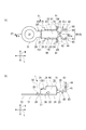
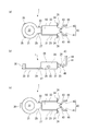
- the temperature sensor which concerns on 1st Embodiment of this invention is shown, (a) is a top view, (b) is a side view.
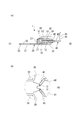
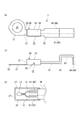
- the temperature sensor which concerns on 1st Embodiment of this invention is shown, (a) is the IIa-IIa arrow directional cross-sectional view of Fig.1 (a), (b) is the IIb part enlarged view of Fig.1 (a).
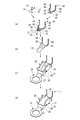
- the modification of the temperature sensor which concerns on 1st Embodiment is shown, (a) is a top view, (b) is a side view, (c) is a top view of another modification.
- the temperature sensor which concerns on 2nd Embodiment of this invention is shown, (a) is a top view, (b) is a side view, (c) is an internal structure figure of the state which is not filled with the filler.
- the temperature sensor 1 includes a temperature sensing element 10, a case 20 that houses the temperature sensing element 10, a lead frame 40 that is electrically connected to the temperature sensing element 10, and a case 20. And a filler 50 for holding the lead frame 40 in the case 20.
- the temperature sensor 1 according to the first embodiment is characterized in that the lead frame 40 is responsible for electrical connection with a circuit board 90 that is a mounting target.
- each component of the temperature sensor 1 will be described in order.
- the side where the lug terminal portion 31 of the case 20 is provided is defined as front (F), and the side where the lead frame 40 is pulled out on the opposite side is defined as rear (R).
- the longitudinal direction L, the width direction W, and the height direction H are defined as shown in FIG.
- the temperature-sensitive element 10 includes an element body 11 and a pair of lead wires 12 and 12 drawn from the element body 11.
- the element body 11 is preferably composed of a thermistor.
- a thermistor has a characteristic in which a change in electric resistance is large with respect to a temperature change, and a resistance value is constant up to a certain temperature with an NTC (negative temperature coefficient) thermistor whose resistance value decreases as the temperature rises.
- NTC negative temperature coefficient
- PTC positive temperature coefficient
- the element body 11 is not limited to the thermistor, and other known temperature sensitive elements can be used.
- the lead wires 12 and 12 electrically connect the element body 11 and the lead frame 40.
- the dumet wire is typically used, but other electric wires can also be used.
- the dumet wire is a composite wire in which an iron-nickel alloy is arranged at the center and copper having good conductivity is clad on the outer layer.
- the temperature sensitive element 10 includes a sealing body 13 made of glass, and the element main body 11 and a predetermined range of lead wires 12 and 12 connected to the element main body 11 are covered with the sealing body 13.
- the case 20 has two functions.
- the first function is a function of accommodating the temperature sensing element 10 and a part of the lead frame 40
- the second function is a part that fixes the temperature sensor 1 to the measurement object and is in contact with the measurement object. This is a function of transferring the heat of the measurement object from the sensor toward the temperature sensing element 10.
- the case 20 having two functions includes an accommodation holding portion 21 and a lug terminal portion 31.
- the case 20 has a housing portion 21 and a lug terminal portion 31 integrally formed by subjecting a metal plate to mechanical processing such as punching and bending.
- the case 20 is preferably made of a metal material having a high heat transfer coefficient, such as an aluminum alloy or a copper alloy.
- the storage and holding portion 21 includes a support wall 22, a pair of side walls 23 and 23 that rise from both edges in the width direction W of the support wall 22, and a front end in the longitudinal direction L of the support wall 22. And a front wall 27 that rises on the side.
- the support wall 22, the side wall 23, and the front wall 27 all have a flat shape with a uniform thickness.
- the accommodation holding portion 21 includes an accommodation space 28 surrounded by a support wall 22, side walls 23, 23 facing the support wall 22, and a front wall 27, and the accommodation space 28 includes the side walls 23, 23 and the front wall 27.
- the side ends 23 and 23 and the rear end side of the support wall 22 are opened.
- a part of the temperature sensing element 10 and the lead frame 40 is housed in the housing space 28 and held by the housing holder 21 via the filler 50.
- each side wall 23 is formed such that the center portion in the front-rear direction is tall and the both ends are short.
- the height of the back here refers to the dimension from the support wall 22.
- the above-mentioned tall central portion of each side wall 23 forms a connection body 24.
- each side wall 23 includes a front support body 25 provided on the front side of the connection body 24 and a rear support body 26 provided on the rear side of the connection body 24 as a support body.
- the front support body 25 and the rear support body 26 are provided at two locations in the front-rear direction and sandwiching the connection body 24.
- a deaeration hole 30 penetrating the front and back is formed in the middle of the longitudinal direction L, as shown in FIG.
- the deaeration holes 30 are provided so that the filler 50 can be distributed inside the accommodation space 28 by discharging the air in the accommodation space 28 to the outside in the step of filling the accommodation space 28 with a filler 50 described later. .
- connection body 24 is used to fix the temperature sensor 1 to the circuit board 90. Specifically, the temperature sensor 1 is fixed to the circuit board 90 together with the lead frame 40 by inserting the connecting body 24 into the slit 91 having a wide slit shape in plan view, which is formed on the circuit board 90. .
- the connection body 24 rises from the side wall 23 so as to be orthogonal to the support wall 22.
- the notch 91 has a dimension in the width direction W that is equal to the dimension in the width direction W defined by the connection bodies 24, 24 at a portion where the pair of connection bodies 24, 24 is inserted.
- the front support body 25 protrudes toward the outside in the width direction W from each side wall 23 as shown in FIGS.
- the front support 25 is parallel to the support wall 22, and the contact surface 251 of the front support 25 is in surface contact with the outer frame 92 connected to the circuit board 90. If the temperature sensor 1 is fixed to the circuit board 90 while the contact surface 251 is in surface contact with the outer frame 92, the case 20 is positioned in the height direction H while the circuit board 90 and the support wall 22 remain parallel. can do.
- the outer frame 92 is removed from the circuit board 90 thereafter.
- the rear support 26 protrudes from the respective side walls 23 toward the outside in the width direction W in the same manner as the front support 25.
- the rear support body 26 has a groove (not shown) extending in a width direction W from the notch 91 of the circuit board 90. ) Is inserted.
- the temperature sensor 1 is positioned in the longitudinal direction L and the width direction W.
- the temperature sensor 1 When the temperature sensor 1 is installed on the circuit board 90 by the front support body 25 and the rear support body 26, the temperature sensor 1 can be easily positioned, and the heat transfer surface of the support wall 22 and the lug terminal portion 31 described later 33 can maintain a state parallel to the circuit board 90. That is, if the circuit board 90 is in a state parallel to the surface in contact with the lug terminal portion 31 of the measurement object, the heat transfer surface 33 can be made parallel to the surface in contact with the lug terminal portion 31 of the measurement object. Therefore, the lug terminal portion 31 comes into close contact with the measurement object in parallel, and the temperature of the measurement object can be accurately measured.
- the front support body 25 and the rear support body 26 regulate the relative positional relationship between the circuit board 90 that is the mounting target and the heat transfer surface 33.
- the lug terminal portion 31 has a circular outer shape in plan view, and a screw hole 32 penetrating the front and back is formed inside thereof.
- a ring-shaped portion around the screw hole 32 forms a heat transfer surface 33 that comes into contact with the measurement object.
- the lug terminal portion 31 can bring either the upper surface or the lower surface in the figure into contact with the measurement object, depending on the positional relationship between the circuit board 90 on which the temperature sensor 1 is mounted and the measurement object.
- the temperature sensor 1 By screwing the screw into the measurement object via the screw hole 32, the temperature sensor 1 can be fixed to the measurement object and the heat transfer surface 33 can be in close contact with the measurement object.
- the heat transfer surface 33 in contact with the measurement object is parallel to the circuit board 90.
- the lug terminal portion 31 is connected to the holding and holding portion 21 by a connecting portion 29 extending forward from the support wall 22, and if the temperature sensor 1 is fixed to the measurement object, the connecting portion 29 and the supporting wall 22. Also fulfills the function of transferring heat.
- the lead frame 40 is electrically connected to a pair of lead wires 12 and 12 of the temperature sensitive element 10 as shown in FIGS. Further, the lead frame 40 is fixed to the circuit board 90 by being inserted into an insertion hole 93 formed in the circuit board 90 and is electrically connected to a corresponding circuit portion of the circuit board 90. As shown in FIGS. 1A and 2B, the lead frame 40 includes a first terminal 41 and a second terminal 45 corresponding to one of the lead wires 12 and 12, respectively. Since the basic configuration is the same except that the first terminal 41 and the second terminal 45 are symmetrical to each other, the configuration of the first terminal 41 will be described below.
- the material of the 1st terminal 41 and the 2nd terminal 45 is arbitrary as long as the objective can be achieved, copper and copper alloy which are excellent in electrical conductivity can be used, for example. Further, the surface of the first terminal 41 and the second terminal 45 can be subjected to surface treatment, for example, plating.
- the first terminal 41 is connected to the lead wire 12 and has a connection portion 42 along the longitudinal direction L and an open leg that is continuous with the connection portion 42 on the same plane.
- a portion 43 and an insertion portion 44 extending in the height direction H and connected to the open leg portion 43 are provided.
- the connecting portion 42 extends straight, and as shown in FIG. 2 (a), the lead wire 12 is placed on one of the upper and lower surfaces, in this embodiment, the upper surface in the drawing, whereby the connecting portion 42 and the lead are connected.
- Line 12 is electrically connected.
- the connection portion 42 and the lead wire 12 are preferably joined by welding or other means at a part or all of the overlapping portions.
- the open leg portion 43 is connected to the connection portion 42 at a predetermined inclination angle and expands toward the outside in the width direction W. By doing so, as shown in FIGS. 1 (a) and 2 (b), the distance between the open leg portion 43 of the first terminal 41 and the open leg portion 43 of the second terminal 45 is widened toward the rear side. Can do.
- the insertion portion 44 is bent so as to be orthogonal to the connection portion 42 and the open leg portion 43 in order to be inserted into the insertion hole 93 formed in the circuit board 90.
- the distal end of the insertion portion 44 is preferably tapered so that it can be easily inserted into the insertion hole 93 formed in the circuit board 90.
- the filler 50 is formed in the housing space 28 of the housing holder 21 in the lead wires 12 and 12 of the temperature sensing element 10 and the lead frame 40 (first terminal 41 and second terminal 45).
- the temperature sensing element 10 and the lead frame 40 are held in the holding holder 21 while covering at least a part of the connecting portions of the connecting portions 42 and 42.
- the filler 50 is made of a resin material having an electrical insulating property and having an adhesive force with respect to the housing holder 21, for example, an epoxy resin. As shown in FIG. 2A, the filler 50 can be composed of two layers of an inner layer 51 and an outer layer 53, that is, a plurality of resin layers, but it can also be composed of only one layer.
- the filler 50 is a metal material constituting the case 20 in order to prevent the filler 50 from being peeled off from the case 20 as the temperature rises.
- the difference between the linear expansion coefficient and the aluminum alloy is small.
- the linear expansion coefficient of pure aluminum is 24 ⁇ 10 ⁇ 6 / ° C.
- the linear expansion coefficient of epoxy resin is 4 to 8 ⁇ 10 ⁇ 5 / ° C.
- the filler 50 is not composed of only a resin material, but an additive for adjusting the linear expansion coefficient of the filler 50 as a whole, specifically, an additive having a smaller linear expansion coefficient than that of an epoxy resin is added. It is preferable.
- this additive for example, particles of aluminum oxide (Al 2 O 3 ) can be used.
- the linear expansion coefficient of aluminum oxide is 7.2 ⁇ 10 ⁇ 6 / ° C.
- the thermal conductivity of aluminum oxide is 237 W / (m ⁇ K), the thermal conductivity of epoxy resin is 0 ⁇ 30 W / (m ⁇ K), and the thermal conductivity of aluminum oxide is higher than that of epoxy resin. Since it is high, the thermal conductivity of the filler 50 can be improved by adding aluminum oxide.
- the particles of aluminum oxide are preferably formed in a leaf shape or a thin plate shape, not in a spherical shape, so that the resin constituting the filler 50 does not settle in the resin when it melts.
- the additive is not limited to aluminum oxide, and for example, an aluminum compound such as aluminum hydroxide (Al (OH) 3 ) or a titanium compound such as titanium oxide (TiO 2 ) can be used.
- the element body 11 of the temperature-sensitive element 10 covered with the filler 50 is firmly fixed to each of the support wall 22, the side walls 23, 23, and the front wall 27 with a predetermined distance therebetween, and the inside of the accommodating space 28. Retained.
- the element body 11 is preferably arranged so as to be as close as possible to the support wall 22 serving as a heat transfer surface.
- the first terminal 41 and the second terminal 45 are covered with the filler 50 while maintaining electrical connection with the lead wires 12 and 12.
- the first terminal 41 and the second terminal 45 are also held inside the accommodation space 28 at a predetermined distance from each of the support wall 22, the side walls 23 and 23, and the front wall 27.
- the filler 50 covers the leading ends of the lead wires 12 and 12 in order to secure the connection state between the lead wires 12 and 12 and the lead frame 40 (first terminal 41 and second terminal 45). However, as shown in FIG. 2B, a minute amount at the tips of the lead wires 12, 12 may be exposed.
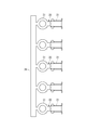
- the case 20 is provided as a member in which the precursors of the plurality of cases 20 are connected in parallel via the carrier 34 on the lug terminal portion 31 side, as shown in FIG.
- the lead frame 40 is also provided as a member connected in parallel via a carrier on the connection portion 42 side.
- This step is a step of electrically connecting the temperature sensitive element 10 and the lead frame 40. Specifically, first, the insertion portion 44 side of the plurality of lead frames 40 connected by the carrier is fixed with a jig (not shown), and the carrier is separated in that state. Even when the carrier is separated, the plurality of lead frames 40 are fixed by the jig, so that the aligned state is maintained. Then, the lead wire 12 and the connection portion 42 are connected by welding in a state where the lead wire 12 of the temperature sensitive element 10 is placed on and brought into contact with the connection portion 42 of the lead frame 40.
- the temperature sensitive element 10 and a part of the lead frame 40 are covered with an inner layer 51 composed of the filler 50.
- an epoxy resin tank (not shown)
- the epoxy resin that forms the inner layer 51 on the temperature sensing element 10 and a part of the lead frame 40 is made.
- Adhere After being lifted from the epoxy resin tank, the attached epoxy resin is cured by heating to form the inner layer 51. Since most of the lead wire 12 is covered with the inner layer 51, the thermosensitive element 10 including the lead wire 12 is bonded to the lead frame 40 with high rigidity by the hardened inner layer 51.
- the temperature sensing element 10 and the lead frame 40 on which the inner layer 51 is formed are disposed at predetermined positions of the housing and holding part 21 of the case 20. Specifically, the lug terminal portion 31 and the carrier 34 connecting the lug terminal portion 31 are fixed by a jig not shown.
- the portion where the inner layer 51 is formed and a part of the lead frame 40 are accommodated in the accommodating / holding portion 21 so that the insertion portion 44 of the lead frame 40 faces upward in the accommodating / holding portion 21.
- the inner layer 51 and the lead frame 40 are held at a position where they do not come into contact with the support wall 22, the side wall 23, and the front wall 27 of the storage holder 21.
- the filling material 50 is formed by filling the accommodation holding portion 21 with an epoxy resin constituting the outer layer 53 and then curing it. Specifically, a solid epoxy resin that forms the outer layer 53 is placed on the temperature sensing element 10 and the lead frame 40 held in the holding holder 21. The epoxy resin is placed at room temperature. Next, the epoxy resin forming the outer layer 53 is heated to lower the viscosity, thereby spreading the epoxy resin in the gap between the housing and holding part 21 and the inner layer 51.
- the deaeration hole 30 is provided in the case 20, when the epoxy resin is filled, the air in the accommodation space 28 is discharged to the outside, and the epoxy resin is distributed inside the accommodation space 28. Can do.
- the outer layer 53 is cured by heating to a higher temperature. Thereby, the outer layer 53 (filler 50) is surrounded by the support wall 22, the front wall 27, and the pair of side walls 23, 23 from four directions. Thereafter, the carrier 34 connected to the lug terminal portion 31 side is separated from the case 20. Thus, a series of manufacturing methods for the temperature sensor 1 of the present embodiment is completed.
- the temperature sensor 1 has a case 20 having a lead frame 40 and a heat transfer surface 33 that comes into contact with an object to be measured, and is connected to the temperature sensitive element 10 by a lead wire 12.
- the lead frame 40 is in electrical connection with the circuit board 90.
- the lead frame 40 is firmly fixed to the case 20 by the filler 50. Therefore, it is possible to reduce the work burden when the temperature sensor 1 is mounted on the circuit board 90.
- the lead wire 12 is responsible for the electrical connection of the temperature sensing element 10 to the circuit board 90 as in Patent Document 1, in addition to the step of installing the case 20 on the circuit board 90, A step of inserting the tip into the insertion hole 93 formed in the circuit board 90 is required.
- the lead frame 40 is firmly fixed to the case 20 via the filler 50. Since the lead frame 40 has higher rigidity than the electric wire, if the lead frame 40 is used in accordance with the distance from the case 20 to the insertion hole 93, the case 20 is aligned with the notch 91 of the circuit board 90 and attached. Only the lead frame 40 is inserted into the insertion hole 93 of the circuit board 90.
- the temperature sensor 1 can reduce the work process at the time of mounting on the circuit board 90, and can improve work efficiency.
- an electric wire when the temperature sensor 1 is mounted on the circuit board 90, it is necessary to allow a certain margin in the length of the electric wire in order to insert the tip of the electric wire into the insertion hole 93. For this reason, even after the electric wires are wired, the space around the circuit board 90 occupies as much as an allowance for the length.
- the lead frame 40 does not need to have a margin like an electric wire, the lead frame 40 does not occupy a space around the circuit board 90 and can save space.
- the temperature sensor 1 can be easily positioned when mounted on the circuit board 90 by the front support body 25 and the rear support body 26 provided on the case 20, and further, the support wall 22 is connected to the circuit board 90. Can be arranged in parallel.
- the heat transfer surface of the temperature sensor 1 becomes a fixed posture with respect to the measurement object, and thus the heat transfer surface 33 of the lug terminal portion 31.
- the support wall 22 and the circuit board 90 are in a parallel state. Can be obtained stably.
- the temperature sensor 1 of the present embodiment can accurately detect the temperature of the measurement object. That is, as shown in FIGS. 1 and 2, the case 20 of the temperature sensor 1 surrounds the filler 50 from the four directions of the support wall 22, the front wall 27, and the pair of side walls 23, 23 of the housing holder 21. . Therefore, according to the temperature sensor 1, since the area for transmitting heat to the temperature sensing element 10 through the filler 50 is wide, the temperature of the measurement object can be quickly transmitted to the temperature sensing element 10.
- the filler 50 contains an additive for adjusting the linear expansion coefficient as a whole, the difference between the linear expansion coefficients of the case 20 and the filler 50 is small. Therefore, according to the temperature sensor 1, even if the circuit board 90 is soldered by the reflow method, it is possible to prevent a gap between the case 20 and the filler 50 or a crack in the filler 50. A reduction in heat transfer performance to the element body 11 via the filler 50 can be prevented.
- FIG. 5 shows a modification of the first embodiment.
- the front support 35 is provided on the lug terminal portion 31.
- a pair of front supports 35, 35 are provided near the front end of the lug terminal portion 31.
- each front support 35 is connected to the lug terminal portion 31 at its side surface, and rises in the height direction H in the same direction as the rear support 26 of the case 20.
- the front end of the front support 35 is at the same height as the rear support 26.
- the distance between the front support 35 and the rear support 26 can be made wider than the distance between the front support 25 and the rear support 26 of the first embodiment.
- the parallel state between the case of the sensor 1 and the circuit board 90 can be maintained more stably.
- the pair of front supports 35, 35 may be provided on the side close to the connecting portion 29. Further, as shown in FIG. 5 (c), only one front support 35 is provided at the front end of the lug terminal portion 31, so that the front support 35 and the pair of rear supports 26, 26 are provided at three points. 20 can also be supported.
- the temperature sensor 2 has a lead frame 60 held by the case 80 that is longer than the temperature sensor 1 of the first embodiment and in plan view,
- the second terminal 45 extends in parallel from the front end to the rear end.
- the same reference numerals as those in the first embodiment are used for the same components as those in the first embodiment.
- the temperature sensor 2 will be described focusing on differences from the temperature sensor 1.
- Each of the first terminal 41 and the second terminal 45 of the lead frame 60 is connected to the first horizontal portion 61 and the first horizontal portion 61 along the longitudinal direction L, as shown in FIGS.
- a first vertical part 62, a second horizontal part 63 connected to the first vertical part 62, and a second vertical part 64 connected to the second horizontal part 63 and forming the connection part 42 are provided.
- the first horizontal portion 61 and the second horizontal portion 63 are parallel to the support wall 22 of the case 20, and the first vertical portion 62 and the second vertical portion 64 are parallel to the front wall 27 of the case 20.
- the 1st horizontal part 61 bears the connection part 42, as shown in FIG.6 (c).
- the lead frame 60 receives the vibration while the temperature sensor 2 is mounted on the circuit board 90 and used. 45 may come into contact. Therefore, the temperature sensor 2 maintains the distance between the first terminal 41 and the second terminal 45 and prevents the first terminal 41 and the second terminal 45 from contacting each other.
- a spacer 70 is provided between 45.
- the spacer 70 is provided by insert molding an epoxy resin.
- the spacer 70 connects the entire lead frame 60 (first terminal 41, second terminal 45) drawn from the case 80 except for the second vertical portion 64. Covered.
- the spacer 70 may be provided intermittently as long as the distance between the first terminal 41 and the second terminal 45 can be maintained.
- the cavities formed by the molds used when the individual spacers 70 are insert-molded can be made smaller than the spacers 70 that continuously cover the entire lead frame 60. The epoxy resin can be easily distributed.
- the temperature sensor 2 is different from the temperature sensor 1 of the first embodiment in that the case 80 is not fixed to the circuit board 90 that is a mounting target.
- the center of the screw hole 32 of the lug terminal portion 31 is shifted from the center of the case 20 in the width direction W to one side in the width direction W.
- the lug terminal portion 31 can be eccentric from the case 20.
- the first embodiment described above is based on the premise that the support wall 22 of the temperature sensor 1 and the circuit board 90 are parallel, but the present invention is not limited to this.
- the posture of the support wall 22 with respect to the circuit board 90 can be adjusted according to the inclination.
- the filler 50 uses an epoxy resin containing aluminum oxide particles as an additive for adjusting the linear material expansion coefficient.
- the present invention is not limited to this. If soldering is performed by means other than the reflow method, a resin containing no additive may be used.
- the lug terminal portion 31 is connected to the accommodation holding portion 21 by the connecting portion 29 extending forward from the support wall 22, but the present invention is not limited to this.
- the lug terminal portion 31 may be connected to the housing holding portion 21 by a connecting portion extending in the height direction H from the front wall 27 and the side wall 23.
- the temperature sensors 1 and 2 provided with the lug terminal portion 31 in the case 20 have been described. It can apply widely to the temperature sensor provided with.
- the support wall 22 of the case 20 is also used as a heat transfer surface. can do.
- the case 20 has a shape that surrounds the filler 50 from four directions, but is not limited thereto, and may have a shape that surrounds the filler 50 from four or more directions.
- the pair of front supports 25 are provided at the same position in the longitudinal direction L, but may be provided at different positions in the longitudinal direction L.
- the rear support 26 is the same.
- the contact surface 251 of the front support 25 is in surface contact with the outer frame 92 connected to the circuit board 90, but the present invention is not limited to this, and the circuit board 90 itself and the measurement object are not limited thereto. It may be in surface contact with other members that are adjacent to the object and subsequently removed.
Abstract
Description
温度センサとして種々の形態が存在するが、例えば特許文献1に記載されるように、センサ本体と、センサ本体を装着するセンサ取付端子と、センサ本体から延出されたリード線と、を備える温度センサが知られている。この温度センサは、温度によって抵抗値が変化するという特性を有するサーミスタがセンサ本体を構成する。
特許文献1に記載される温度センサは、センサ取付端子に形成されたネジ取付孔を介して、測定対象物にねじ止めにより固定される。
また、特許文献1に記載される温度センサは、リード線の先端に取り付けられたコネクタを介して、温度を検知するための回路に電気的に接続され、リード線が当該回路との電気的な接続を担う。
しかし、温度センサを例えば回路基板に実装する際の工程を少なくすることで、作業負担を軽減することが好ましい。
そこで本発明は、装着対象物に実装する際の作業負担を軽減できる温度センサを提供することを課題とする。
リードフレームは、電線に比べて剛性が高いので、ケースを装着対象物に位置合わせして装着するだけで、リードフレームを例えば回路基板の挿通孔へ挿入できる。したがって、本発明の温度センサによれば、回路基板に実装する際の作業工程を減らすことができ、作業効率を向上させることができる。
また、リードフレームは、電線のようにその先端を挿通孔に挿入するため長さに余裕を持たせる必要がないため、回路基板の周囲のスペースを占めることがなく、省スペース化を図ることができる。
[第1実施形態]
温度センサ1は、図1及び図2に示すように、感温素子10と、感温素子10を収容するケース20と、感温素子10と電気的に接続されるリードフレーム40と、ケース20に収容される感温素子10とリードフレーム40をケース20に保持する充填材50と、を備えている。
第1実施形態に係る温度センサ1は、図1(b)に示すように、装着対象物である回路基板90との電気的な接続をリードフレーム40が担うところに特徴を有する。以下、温度センサ1の各構成要素について順に説明する。
なお、温度センサ1において、ケース20のラグ端子部31が設けられる側を前(F)と定義し、その逆側でリードフレーム40が引き出される側を後(R)と定義する。また、温度センサ1において、長手方向L、幅方向W及び高さ方向Hを、図1に示す通りに定義する。
感温素子10は、図2に示すように、素子本体11と、素子本体11から引き出される一対のリード線12,12と、を備える。
素子本体11は、好ましくはサーミスタ(thermistor)からなる。サーミスタは、温度変化に対して電気抵抗の変化が大きい特性を有し、温度が上がると抵抗値が下がるNTC(negative temperature coefficient)サーミスタと、ある温度まで抵抗値が一定で、ある温度を境に急激に抵抗値が高くなるPTC(positive temperature coefficient)サーミスタがある。素子本体11としては、サーミスタに限らず、他の公知の感温素子を用いることができる。
リード線12,12は、素子本体11とリードフレーム40を電気的に接続する。リード線12,12としては、典型的にはジュメット線(Dumet wire)が用いられるが、他の電線を用いることもできる。なお、ジュメット線は、中心に鉄ニッケル合金を配し、外層に導電率の良い銅をクラッドした複合線である。
感温素子10は、ガラスからなる封止体13を備え、素子本体11と、素子本体11と接続されるリード線12,12の所定範囲とが封止体13により覆われる。
次に、ケース20について、図1及び図2を参照して説明する。
ケース20は、二つの機能を有している。第一の機能は、感温素子10とリードフレーム40の一部とを収容する機能であり、第二の機能は、温度センサ1を測定対象物に固定するとともに、測定対象物と接触する部位から測定対象物の熱を感温素子10に向けて伝達する機能である。
なお、ケース20は、金属板に打ち抜き加工、折り曲げ加工などの機械加工を施すことにより、収容保持部21とラグ端子部31が一体的に形成されている。熱伝達の機能を担保するために、ケース20は熱伝達率の高い金属材料、例えばアルミニウム合金、銅合金から構成されることが好ましい。
収容保持部21は、支持壁22と、支持壁22に対向する側壁23,23と、前壁27とによって取り囲まれる収容空間28を備え、この収容空間28は、側壁23,23と前壁27の先端部が開放されているとともに、側壁23,23と支持壁22の後端側が開放されている。感温素子10及びリードフレーム40の一部は、この収容空間28に収容されるとともに、充填材50を介して収容保持部21に保持される。
ねじ孔32を介してねじを測定対象物にねじ込むことにより、温度センサ1を測定対象物に固定するとともに、伝熱面33を測定対象物に密着できる。測定対象物と接する伝熱面33は回路基板90と平行をなす。
ラグ端子部31は、支持壁22から前方に向けて延設された連結部29により収容保持部21と繋がっており、温度センサ1を測定対象物に固定すれば、連結部29及び支持壁22も熱を伝える機能を果たす。
リードフレーム40は、図2(a),(b)に示すように、感温素子10の一対のリード線12,12と電気的に接続される。また、リードフレーム40は、回路基板90に形成された挿通孔93に挿入されることで回路基板90に固定されるとともに、回路基板90の対応する回路部分と電気的に接続される。
リードフレーム40は、図1(a),図2(b)に示すように、リード線12,12のそれぞれ一方に対応する第一端子41と第二端子45を備えている。第一端子41と第二端子45は、互いに対称の形状をなしていることを除く基本的な構成は同じであるから、以下では第一端子41についてその構成を説明する。
なお、第一端子41及び第二端子45の材質はその目的を達成できる限り任意であるが、例えば電気伝導度の優れる銅、銅合金を用いることができる。また、第一端子41及び第二端子45の表面に表面処理、例えばメッキを施すこともできる。
接続部42は真っ直ぐに延びており、図2(a)に示すように、その上下の一方の面、本実施形態では図中の上面にリード線12が載せられることで、接続部42とリード線12が電気的に接続される。接続部42とリード線12は、電気的な接続を確保するために、互いに重複する部分の一部または全部が溶接、その他の手段により接合されることが好ましい。
開脚部43は、接続部42に対して所定の傾斜角度を有して連なっており、幅方向Wの外側に向けて拡開する。こうすることで、図1(a),図2(b)に示すように、第一端子41の開脚部43と第二端子45の開脚部43の間隔を後側に向けて広げることができる。
挿入部44は、回路基板90に形成された挿通孔93に挿入するために、接続部42及び開脚部43に対して直交するように、折り曲げられる。挿入部44の先端は、回路基板90に形成された挿通孔93に挿入しやすいようにテーパ状にすることが好ましい。
充填材50は、図2(a)に示すように、収容保持部21の収容空間28において、感温素子10のリード線12,12とリードフレーム40(第一端子41と第二端子45)の接続部42,42の接続部分の少なくとも一部を覆うとともに、感温素子10とリードフレーム40を収容保持部21に保持する。
酸化アルミニウムの粒子は、充填材50を構成する樹脂が溶融する際に、樹脂の中で沈降しないように、球状ではなく、リーフ状、薄板状に形成されているのが好ましい。
添加剤としては、酸化アルミニウムに限るものではなく、例えば、水酸化アルミニウム(Al(OH)3)等のアルミニウム化合物、又は酸化チタン(TiO2)等のチタン化合物を用いることができる。
第一端子41と第二端子45は、リード線12,12と電気的な接続を保ったままで充填材50に覆われる。第一端子41と第二端子45もまた、支持壁22、側壁23,23及び前壁27のそれぞれから所定の間隔を隔てて、収容空間28の内部に保持される。
充填材50は、リード線12,12の先端まで覆うことが、リード線12,12とリードフレーム40(第一端子41と第二端子45)の接続状態を確保する上で好ましい。ただし、図2(b)に示すようにリード線12,12の先端の微小量が露出していてもよい。
次に、温度センサ1を製造する手順について、図3を参照して説明する。
この製造方法は、接続工程、被覆工程、配置工程、充填工程及び硬化工程を有している。
なお、当該製造方法において、ケース20は、図4に示すように、ラグ端子部31の側でキャリア34を介して複数のケース20の前駆体が並列に繋がっている部材として提供される。図示を省略するが、リードフレーム40も、接続部42の側でキャリアを介して並列に繋がっている部材として提供される。
本工程は、感温素子10とリードフレーム40を電気的に接続する工程である。
具体的には、まず、キャリアにより繋がった複数のリードフレーム40の挿入部44の側を、図示を省略する冶具で固定し、その状態でキャリアを切り離す。キャリアを切り離しても、複数のリードフレーム40は、治具により固定されているので、整列した状態が維持される。
そして、感温素子10のリード線12をリードフレーム40の接続部42に載せて接触させた状態で、リード線12と接続部42を溶接により接続する。
次に、感温素子10とリードフレーム40の一部を充填材50により構成される内層51で被覆する。
具体的には、感温素子10とリードフレーム40の一部を、図示を省略するエポキシ樹脂槽に浸漬することで、感温素子10とリードフレーム40の一部に内層51をなすエポキシ樹脂を付着させる。エポキシ樹脂槽から引き揚げた後に、付着したエポキシ樹脂を加熱することにより硬化させて、内層51を形成する。リード線12は内層51によりほとんどが覆い隠されるので、硬化した内層51によりリード線12を含めた感温素子10は、リードフレーム40に高い剛性をもって接合される。
次に、内層51が形成された感温素子10とリードフレーム40は、ケース20の収容保持部21の所定位置に配置される。
具体的には、ラグ端子部31及びラグ端子部31を繋いでいるキャリア34を、図示を省略する冶具により固定する。次に、収容保持部21に、リードフレーム40の挿入部44が上になるようにして、内層51が形成された部分とリードフレーム40の一部を収容保持部21内に収容する。内層51とリードフレーム40は、収容保持部21の支持壁22、側壁23及び前壁27と接触しない位置に保持される。
次に、収容保持部21に、外層53を構成するエポキシ樹脂を充填してから硬化させることで、充填材50を形成する。
具体的には、収容保持部21に保持されている感温素子10とリードフレーム40の上に外層53をなす固体状のエポキシ樹脂を載せる。エポキシ樹脂を載せるのは室温で行われる。
次に、外層53をなすエポキシ樹脂を加温して粘度を下げることで、収容保持部21と内層51の間の隙間にエポキシ樹脂を行き渡らせる。ここで、ケース20には、脱気孔30が設けられているので、エポキシ樹脂が充填される際に、収容空間28の空気が外部に排出され、収容空間28の内部にエポキシ樹脂を行き渡らせることができる。
その後、ラグ端子部31の側と繋がっているキャリア34をケース20から切り離す。これで、本実施形態の温度センサ1の一連の製造方法が完了する。
以下、本実施形態の温度センサ1及びその製造方法が奏する効果について説明する。
温度センサ1は、図1及び図2に示すように、リードフレーム40と、測定対象物と接触する伝熱面33を有するケース20を有しており、リード線12によって感温素子10に接続されるリードフレーム40が回路基板90との電気的な接続を担う。しかも、リードフレーム40は充填材50によりケース20に強固に固定される。
したがって、温度センサ1を回路基板90に実装する際の作業負担を軽減することができる。つまり、特許文献1のように感温素子10の回路基板90との電気的な接続をリード線12が担うものとすると、ケース20を回路基板90に設置する工程の他に、リード線12の先端を回路基板90に形成された挿通孔93に挿入する工程が必要になる。これに対し温度センサ1は、リードフレーム40が充填材50を介してケース20に強固に固定されている。リードフレーム40は、電線に比べて剛性が高いので、ケース20から挿通孔93までの距離に合わせたものが用いられていれば、ケース20を回路基板90の切り込み91に位置合わせして装着するだけで、リードフレーム40を回路基板90の挿通孔93へ挿入される。したがって、温度センサ1は、回路基板90に実装する際の作業工程を減らすことができ、作業効率を向上させることができる。
また、電線を用いる場合は、温度センサ1を回路基板90に実装する際に、電線の先端を挿通孔93に挿入するのに、電線の長さにある程度余裕を持たせる必要がある。このため、電線を配線した後にも、長さに余裕を持たせた分だけ、回路基板90の周囲のスペースを占める。これに対し、リードフレーム40は、電線のように余裕を持たせる必要がないため、回路基板90の周囲のスペースを占めることがなく、省スペース化を図ることができる。
特に、前方支持体25と後方支持体26は、接続体24の前側と後側とで所定の間隔をあけて複数の箇所に設けられているので、支持壁22と回路基板90の平行な状態を安定して得ることができる。
したがって温度センサ1によれば、回路基板90にリフロー方式で半田付けされても、ケース20と充填材50の間に隙間ができたり、充填材50に亀裂が入ったりするのを防止できるので、充填材50を介する素子本体11への伝熱性能の低下を防ぐことができる。
図5は、第1実施形態の変形例を示す。
この変形例にかかる温度センサ1は、ケース20に前方支持体25を設ける代わりに、ラグ端子部31に前方支持体35を設けている。
具体的には、図5(a)に示すように、ラグ端子部31の前端寄りに、一対の前方支持体35,35が設けられている。それぞれの前方支持体35は、図5(b)に示すように、ラグ端子部31とその側面で繋がっており、高さ方向Hにケース20の後方支持体26と同じ向きに立ち上がっている。前方支持体35の先端は、後方支持体26と同じ高さになっている。
次に、本発明の第2実施形態に係る温度センサ2について、図6を参照して説明する。
温度センサ2は、図6(a)に示すように、ケース80に保持されるリードフレーム60が、第1実施形態の温度センサ1よりも長く、かつ、平面視して、第一端子41と第二端子45が前端から後端まで平行に延びている。なお、第2実施形態において第1実施形態と同様の構成要素には、第1実施形態と同じ符号を用いる。以下、温度センサ2について、温度センサ1との相違点を中心に説明する。
10 感温素子
11 素子本体
12 リード線
13 封止体
20 ケース
21 収容保持部
22 支持壁
23 側壁
24 接続体
25 前方支持体
251 当接面
26 後方支持体
27 前壁
28 収容空間
29 連結部
30 脱気孔
31 ラグ端子部
32 ねじ孔
33 伝熱面
34 キャリア
35 前方支持体
40 リードフレーム
41 第一端子
42 接続部
43 開脚部
44 挿入部
45 第二端子
50 充填材
51 内層
53 外層
60 リードフレーム
61 第一水平部
62 第一垂直部
63 第二水平部
64 第二垂直部
70 スペーサ
90 回路基板
91 切込み
92 外枠
93 挿通孔
H 高さ方向
L 長手方向
W 幅方向
Claims (8)
- 素子本体と、前記素子本体から引き出される一対のリード線と、を有する感温素子と、
前記感温素子を収容し、温度の測定対象物に接する伝熱面を有するケースと、
前記リード線のそれぞれと電気的に接続され、前記ケースから引き出される一対のリードフレームと、
前記ケースに収容される前記感温素子と前記リードフレームとを覆い、前記接続の状態を維持して前記感温素子と前記リードフレームを前記ケースに保持する充填材と、
を備えることを特徴とする温度センサ。 - 前記充填材は、
前記ケースの内部において、または、前記ケースの内部と外部において、前記リード線と前記リードフレームの接続部分の少なくとも一部を覆う、
請求項1に記載の温度センサ。 - 前記ケースは、
前記充填材を取り囲む、
請求項1又は請求項2に記載の温度センサ。 - 前記ケースは、
前記測定対象物に前記ケースを固定し、前記伝熱面を有するラグ端子を備える、
請求項1~請求項3のいずれか一項に記載の温度センサ。 - 前記温度センサは、
装着対象物に装着されて前記測定対象物の温度を測定し、
前記ケースは、
前記伝熱面と対向する側に、前記装着対象物との接続を担う接続体を備える、
請求項1~請求項4のいずれか一項に記載の温度センサ。 - 前記ケースは、
前記装着対象物と前記伝熱面の相対的な位置関係を規制する支持体を備える、
請求項4又は請求項5に記載の温度センサ。 - 前記支持体は、
前記リードフレームが引き出される前後方向であって、前記接続体を挟む複数の箇所に設けられる、
請求項6に記載の温度センサ。 - 一対の前記リードフレームは、相互の間隔を維持するスペーサを備える、
請求項1~請求項7のいずれか一項に記載の温度センサ。
Priority Applications (6)
| Application Number | Priority Date | Filing Date | Title |
|---|---|---|---|
| EP17891278.8A EP3431944B1 (en) | 2017-01-16 | 2017-01-16 | Temperature sensor |
| CN202111612422.0A CN114216578A (zh) | 2017-01-16 | 2017-01-16 | 温度传感器 |
| US16/090,469 US11105688B2 (en) | 2017-01-16 | 2017-01-16 | Attaching a thermistor on a case |
| CN201780021019.6A CN109073473A (zh) | 2017-01-16 | 2017-01-16 | 温度传感器 |
| JP2017521180A JP6371002B1 (ja) | 2017-01-16 | 2017-01-16 | 温度センサ |
| PCT/JP2017/001262 WO2018131164A1 (ja) | 2017-01-16 | 2017-01-16 | 温度センサ |
Applications Claiming Priority (1)
| Application Number | Priority Date | Filing Date | Title |
|---|---|---|---|
| PCT/JP2017/001262 WO2018131164A1 (ja) | 2017-01-16 | 2017-01-16 | 温度センサ |
Publications (1)
| Publication Number | Publication Date |
|---|---|
| WO2018131164A1 true WO2018131164A1 (ja) | 2018-07-19 |
Family
ID=62840297
Family Applications (1)
| Application Number | Title | Priority Date | Filing Date |
|---|---|---|---|
| PCT/JP2017/001262 WO2018131164A1 (ja) | 2017-01-16 | 2017-01-16 | 温度センサ |
Country Status (5)
| Country | Link |
|---|---|
| US (1) | US11105688B2 (ja) |
| EP (1) | EP3431944B1 (ja) |
| JP (1) | JP6371002B1 (ja) |
| CN (2) | CN114216578A (ja) |
| WO (1) | WO2018131164A1 (ja) |
Cited By (2)
| Publication number | Priority date | Publication date | Assignee | Title |
|---|---|---|---|---|
| JP2020201134A (ja) * | 2019-06-11 | 2020-12-17 | 新日本無線株式会社 | 弾性表面波センサおよびそれを用いた計測システム |
| JP2021001855A (ja) * | 2019-06-21 | 2021-01-07 | 甲神電機株式会社 | 温度センサのリードフレーム構造 |
Families Citing this family (7)
| Publication number | Priority date | Publication date | Assignee | Title |
|---|---|---|---|---|
| US20190069443A1 (en) * | 2017-08-31 | 2019-02-28 | Ling Long | Liquid-cooling termination structure having temperature sensing function |
| JP6916228B2 (ja) * | 2019-02-26 | 2021-08-11 | 株式会社芝浦電子 | 温度センサ |
| DE202019104670U1 (de) * | 2019-08-26 | 2019-12-10 | Tdk Electronics Ag | Sensor |
| WO2021070898A1 (ja) * | 2019-10-10 | 2021-04-15 | 株式会社芝浦電子 | 温度センサおよび電動機 |
| JP7190609B1 (ja) | 2021-09-09 | 2022-12-15 | 株式会社芝浦電子 | 温度センサ |
| CN114705322B (zh) * | 2022-06-07 | 2022-09-30 | 海南浙江大学研究院 | 温度链及其使用方法 |
| CN116940815A (zh) * | 2022-07-25 | 2023-10-24 | 株式会社芝浦电子 | 温度传感器 |
Citations (3)
| Publication number | Priority date | Publication date | Assignee | Title |
|---|---|---|---|---|
| JPH0424032U (ja) * | 1990-06-20 | 1992-02-27 | ||
| JP2005283149A (ja) * | 2004-03-26 | 2005-10-13 | Tdk Corp | 感温素子を備えた電子部品 |
| JP2013015430A (ja) * | 2011-07-05 | 2013-01-24 | Shibaura Electronics Co Ltd | 温度センサ及びセンサ取付用の端子 |
Family Cites Families (21)
| Publication number | Priority date | Publication date | Assignee | Title |
|---|---|---|---|---|
| JPH0726668Y2 (ja) * | 1986-07-31 | 1995-06-14 | 株式会社村田製作所 | 温度検知用サーミスタ |
| JPH0755833Y2 (ja) * | 1988-12-09 | 1995-12-20 | オムロン株式会社 | 温度補償素子内蔵コネクタ |
| FR2652951B1 (fr) * | 1989-10-05 | 1996-05-31 | Accumulateurs Fixes | Capteur de temperature pour batteries d'accumulateurs. |
| US5749656A (en) * | 1995-08-11 | 1998-05-12 | General Motors Corporation | Thermal probe assembly with mold-over crimp sensor packaging |
| JP3787795B2 (ja) * | 1997-03-31 | 2006-06-21 | 株式会社大泉製作所 | 表面温度センサ |
| JP3705093B2 (ja) * | 1999-08-20 | 2005-10-12 | 株式会社村田製作所 | 温度センサの装着方法、および被温度検出物の温度検出構造 |
| US6918696B2 (en) | 2003-01-15 | 2005-07-19 | Denso Corporation | Temperature sensor and method for manufacturing the same |
| DE102007045179A1 (de) * | 2007-09-21 | 2009-04-02 | Robert Bosch Gmbh | Kontaktierungsmodul für Sensor mit begrenztem Bauraum |
| JP2010032493A (ja) * | 2008-06-25 | 2010-02-12 | Ngk Spark Plug Co Ltd | 温度センサ |
| CN201382821Y (zh) * | 2009-03-27 | 2010-01-13 | 杨志强 | 一种改进的测温环 |
| KR101008310B1 (ko) | 2010-07-30 | 2011-01-13 | 김선기 | 세라믹 칩 어셈블리 |
| JP5523982B2 (ja) * | 2010-08-16 | 2014-06-18 | 株式会社芝浦電子 | 温度センサ |
| CN202075053U (zh) * | 2011-05-27 | 2011-12-14 | 西安远征智能软件有限公司 | 开关柜触头温度测量环 |
| CN202547820U (zh) * | 2012-03-02 | 2012-11-21 | 恒新基电子(青岛)有限公司 | 螺丝型温度传感器 |
| CN102914376B (zh) * | 2012-10-16 | 2014-12-10 | 珠海黑石电气自动化科技有限公司 | 等电位测温装置 |
| JP6454062B2 (ja) * | 2013-03-21 | 2019-01-16 | 矢崎総業株式会社 | 圧着端子 |
| JP6467637B2 (ja) * | 2013-10-15 | 2019-02-13 | パナソニックIpマネジメント株式会社 | 温度センサおよびその製造方法 |
| DE102013222142A1 (de) * | 2013-10-30 | 2015-04-30 | Tyco Electronics Amp Gmbh | Dichtungsschonendes Kontaktelement mit einem Lagesicherungselement |
| DE102014116658B4 (de) * | 2014-11-14 | 2016-06-23 | Krohne Ag | Vorrichtung zur Temperaturbestimmung sowie Messanordnung zur Bestimmung des Durchflusses |
| CN204165670U (zh) * | 2014-11-20 | 2015-02-18 | 国家电网公司 | 一种用于户外高电压环境的声表面波温度传感器 |
| CN105628242A (zh) * | 2015-12-30 | 2016-06-01 | 中国科学院国家天文台南京天文光学技术研究所 | 检测物体表面温度分布和梯度的方法和设备 |
-
2017
- 2017-01-16 US US16/090,469 patent/US11105688B2/en active Active
- 2017-01-16 JP JP2017521180A patent/JP6371002B1/ja active Active
- 2017-01-16 CN CN202111612422.0A patent/CN114216578A/zh active Pending
- 2017-01-16 CN CN201780021019.6A patent/CN109073473A/zh active Pending
- 2017-01-16 WO PCT/JP2017/001262 patent/WO2018131164A1/ja active Application Filing
- 2017-01-16 EP EP17891278.8A patent/EP3431944B1/en active Active
Patent Citations (3)
| Publication number | Priority date | Publication date | Assignee | Title |
|---|---|---|---|---|
| JPH0424032U (ja) * | 1990-06-20 | 1992-02-27 | ||
| JP2005283149A (ja) * | 2004-03-26 | 2005-10-13 | Tdk Corp | 感温素子を備えた電子部品 |
| JP2013015430A (ja) * | 2011-07-05 | 2013-01-24 | Shibaura Electronics Co Ltd | 温度センサ及びセンサ取付用の端子 |
Cited By (4)
| Publication number | Priority date | Publication date | Assignee | Title |
|---|---|---|---|---|
| JP2020201134A (ja) * | 2019-06-11 | 2020-12-17 | 新日本無線株式会社 | 弾性表面波センサおよびそれを用いた計測システム |
| JP7235378B2 (ja) | 2019-06-11 | 2023-03-08 | 日清紡マイクロデバイス株式会社 | 弾性表面波センサおよびそれを用いた計測システム |
| JP2021001855A (ja) * | 2019-06-21 | 2021-01-07 | 甲神電機株式会社 | 温度センサのリードフレーム構造 |
| JP7469750B2 (ja) | 2019-06-21 | 2024-04-17 | 甲神電機株式会社 | 温度センサのリードフレーム構造 |
Also Published As
| Publication number | Publication date |
|---|---|
| JP6371002B1 (ja) | 2018-08-08 |
| EP3431944B1 (en) | 2020-04-01 |
| US11105688B2 (en) | 2021-08-31 |
| CN114216578A (zh) | 2022-03-22 |
| EP3431944A1 (en) | 2019-01-23 |
| CN109073473A (zh) | 2018-12-21 |
| JPWO2018131164A1 (ja) | 2019-01-17 |
| EP3431944A4 (en) | 2019-05-15 |
| US20190120697A1 (en) | 2019-04-25 |
Similar Documents
| Publication | Publication Date | Title |
|---|---|---|
| JP6371002B1 (ja) | 温度センサ | |
| KR100369312B1 (ko) | 온도 센서, 온도 센서의 제조 방법, 및 온도 센서를 회로기판에 장착하는 방법 | |
| JP5484336B2 (ja) | 制限された構造スペースを備えるセンサのためのコンタクトモジュール | |
| JP5098772B2 (ja) | 電装品ユニット | |
| JP6012842B2 (ja) | 絶縁チューブ付き撮像モジュール、レンズ付き撮像モジュール、及び内視鏡 | |
| JP4943930B2 (ja) | 立体回路部品の取付構造 | |
| US8529127B2 (en) | Construction and manufacturing method for a sensor of a thermal flow measuring device | |
| CN105097154A (zh) | 电流检测用电阻器 | |
| US20140109664A1 (en) | Temperature sensor and thermal flow-measuring device | |
| JP6318241B2 (ja) | オプトエレクトロニクス装置 | |
| JP5232582B2 (ja) | コネクタ | |
| CA2698144C (en) | Fixation structure for connector of in-vehicle controller | |
| EP1933336B1 (en) | Metal foil resistor | |
| JP4547475B2 (ja) | 平板型温度センサ | |
| US6869293B2 (en) | Electronic device having integrated connector | |
| JP2000340403A (ja) | 温度センサおよびその製造方法 | |
| US20200080896A1 (en) | Infrared sensor mounting member | |
| JP6341136B2 (ja) | 温度センサ | |
| JP6856357B2 (ja) | ヒータ | |
| JP2004151009A (ja) | 駆動用集積回路の温度センサ取付構造およびプリント配線基板の温度センサ取付構造 | |
| JP6683141B2 (ja) | 半導体装置の製造方法および端子固定治具 | |
| KR200459384Y1 (ko) | 서미스터 | |
| JP3007342U (ja) | 温度検知用ptcサーミスタ | |
| JP2020134475A (ja) | 温度センサ | |
| JPH0559954U (ja) | 水晶振動子用気密端子 |
Legal Events
| Date | Code | Title | Description |
|---|---|---|---|
| ENP | Entry into the national phase |
Ref document number: 2017521180 Country of ref document: JP Kind code of ref document: A |
|
| WWE | Wipo information: entry into national phase |
Ref document number: 2017891278 Country of ref document: EP |
|
| ENP | Entry into the national phase |
Ref document number: 2017891278 Country of ref document: EP Effective date: 20181002 |
|
| 121 | Ep: the epo has been informed by wipo that ep was designated in this application |
Ref document number: 17891278 Country of ref document: EP Kind code of ref document: A1 |
|
| NENP | Non-entry into the national phase |
Ref country code: DE |