JP5523982B2 - 温度センサ - Google Patents
温度センサ Download PDFInfo
- Publication number
- JP5523982B2 JP5523982B2 JP2010181536A JP2010181536A JP5523982B2 JP 5523982 B2 JP5523982 B2 JP 5523982B2 JP 2010181536 A JP2010181536 A JP 2010181536A JP 2010181536 A JP2010181536 A JP 2010181536A JP 5523982 B2 JP5523982 B2 JP 5523982B2
- Authority
- JP
- Japan
- Prior art keywords
- protective tube
- thermistors
- wires
- holder
- temperature sensor
- Prior art date
- Legal status (The legal status is an assumption and is not a legal conclusion. Google has not performed a legal analysis and makes no representation as to the accuracy of the status listed.)
- Active
Links
- 230000001681 protective effect Effects 0.000 claims description 93
- 230000002093 peripheral effect Effects 0.000 claims description 22
- WABPQHHGFIMREM-UHFFFAOYSA-N lead(0) Chemical compound [Pb] WABPQHHGFIMREM-UHFFFAOYSA-N 0.000 claims description 18
- 239000000945 filler Substances 0.000 claims description 17
- 239000011810 insulating material Substances 0.000 claims description 7
- 239000000463 material Substances 0.000 claims description 5
- 238000009413 insulation Methods 0.000 claims description 4
- XLYOFNOQVPJJNP-UHFFFAOYSA-N water Substances O XLYOFNOQVPJJNP-UHFFFAOYSA-N 0.000 description 7
- 230000004043 responsiveness Effects 0.000 description 5
- 230000004044 response Effects 0.000 description 3
- 238000001514 detection method Methods 0.000 description 2
- 239000003822 epoxy resin Substances 0.000 description 2
- 239000012530 fluid Substances 0.000 description 2
- 229920000647 polyepoxide Polymers 0.000 description 2
- 230000015556 catabolic process Effects 0.000 description 1
- 239000003795 chemical substances by application Substances 0.000 description 1
- 210000000078 claw Anatomy 0.000 description 1
- 239000011248 coating agent Substances 0.000 description 1
- 238000000576 coating method Methods 0.000 description 1
- 238000006731 degradation reaction Methods 0.000 description 1
- 238000003745 diagnosis Methods 0.000 description 1
- 238000010586 diagram Methods 0.000 description 1
- 239000011521 glass Substances 0.000 description 1
- 238000004519 manufacturing process Methods 0.000 description 1
- 239000002184 metal Substances 0.000 description 1
- 238000000034 method Methods 0.000 description 1
- 229920001296 polysiloxane Polymers 0.000 description 1
- 238000003825 pressing Methods 0.000 description 1
- 230000000644 propagated effect Effects 0.000 description 1
- 229920005989 resin Polymers 0.000 description 1
- 239000011347 resin Substances 0.000 description 1
- 230000035945 sensitivity Effects 0.000 description 1
- 238000007711 solidification Methods 0.000 description 1
- 230000008023 solidification Effects 0.000 description 1
- 238000003892 spreading Methods 0.000 description 1
- 229910001220 stainless steel Inorganic materials 0.000 description 1
- 239000010935 stainless steel Substances 0.000 description 1
- 239000002966 varnish Substances 0.000 description 1
- 238000004078 waterproofing Methods 0.000 description 1
- 238000003466 welding Methods 0.000 description 1
Images


Classifications
-
- G—PHYSICS
- G01—MEASURING; TESTING
- G01K—MEASURING TEMPERATURE; MEASURING QUANTITY OF HEAT; THERMALLY-SENSITIVE ELEMENTS NOT OTHERWISE PROVIDED FOR
- G01K7/00—Measuring temperature based on the use of electric or magnetic elements directly sensitive to heat ; Power supply therefor, e.g. using thermoelectric elements
- G01K7/16—Measuring temperature based on the use of electric or magnetic elements directly sensitive to heat ; Power supply therefor, e.g. using thermoelectric elements using resistive elements
- G01K7/22—Measuring temperature based on the use of electric or magnetic elements directly sensitive to heat ; Power supply therefor, e.g. using thermoelectric elements using resistive elements the element being a non-linear resistance, e.g. thermistor
-
- G—PHYSICS
- G01—MEASURING; TESTING
- G01K—MEASURING TEMPERATURE; MEASURING QUANTITY OF HEAT; THERMALLY-SENSITIVE ELEMENTS NOT OTHERWISE PROVIDED FOR
- G01K1/00—Details of thermometers not specially adapted for particular types of thermometer
- G01K1/08—Protective devices, e.g. casings
-
- G—PHYSICS
- G01—MEASURING; TESTING
- G01K—MEASURING TEMPERATURE; MEASURING QUANTITY OF HEAT; THERMALLY-SENSITIVE ELEMENTS NOT OTHERWISE PROVIDED FOR
- G01K1/00—Details of thermometers not specially adapted for particular types of thermometer
- G01K1/16—Special arrangements for conducting heat from the object to the sensitive element
-
- G—PHYSICS
- G01—MEASURING; TESTING
- G01K—MEASURING TEMPERATURE; MEASURING QUANTITY OF HEAT; THERMALLY-SENSITIVE ELEMENTS NOT OTHERWISE PROVIDED FOR
- G01K7/00—Measuring temperature based on the use of electric or magnetic elements directly sensitive to heat ; Power supply therefor, e.g. using thermoelectric elements
- G01K7/16—Measuring temperature based on the use of electric or magnetic elements directly sensitive to heat ; Power supply therefor, e.g. using thermoelectric elements using resistive elements
- G01K2007/163—Measuring temperature based on the use of electric or magnetic elements directly sensitive to heat ; Power supply therefor, e.g. using thermoelectric elements using resistive elements provided with specially adapted connectors
Description
給湯器の湯や、各種の雰囲気等の温度を検出する温度センサにおいては、有底筒状のケース内にサーミスタを収容し、流体の流路内にはケースのみを露出させる構成が採用されている(例えば、特許文献1〜5参照。)。センサと流体との絶縁、防水等を図るためである。
本発明は、このような技術的課題に基づいてなされたもので、信頼性を確保しつつ、応答性を高めるとともに、二つのサーミスタの応答を均一化することのできる温度センサを提供することを目的とする。
ここで、ホルダーは、外周面に平面部を有し、当該ホルダーを保護管内に挿入したときに、保護管の内周面と平面部との間に空隙が形成されるようにする。そして、保護管内には絶縁性を有した硬化性材料からなる充填剤が充填され、充填剤により、保護管内のサーミスタ、配線、リード線、ホルダーが固定される。ホルダーの外周面の平面部により保護管の内周面と平面部との間に空隙が形成されることで、保護管内での充填剤の流路を確保することができ、保護管内の全体に充填剤を行き渡らせることができる。
さらに、ホルダーは、二つのサーミスタのそれぞれに対応して設ける。この場合、サーミスタのそれぞれに接続された二本の配線と、当該二本の配線に接続される二本のリード線との接続部をホルダーで保持する。
ホルダーには、二本の配線と、当該二本の配線に接続される二本のリード線とを収容する溝が形成され、溝が開口した側の面を、保護管内で他のホルダーに対向させて設けるのが好ましい。これにより、配線およびリード線と保護管との間にはホルダーが介在し、その耐電圧性能を高めることができる。
そして、ホルダーの外周面の平面部により保護管の内周面と平面部との間に空隙が形成されることで、保護管内での充填剤の流路を確保し、保護管内の全体に充填剤を行き渡らせて、サーミスタ、配線、リード線と、保護管との絶縁、固定を確実に行うことができる。これにより温度センサの小型化が可能となり、従来の温度センサと取付形状を変更することなく使用することもできる。
また、二つのサーミスタを、保護管内で並列に設けて保護管の内周面と近接させることで、保護管の外部の熱が保護管を介してサーミスタに伝達されやすく、温度センサを応答性に優れるものとすることができる。
このようにして、二つのサーミスタを備える温度センサにおいても、信頼性を確保しつつ、応答性を高めることが可能となる。
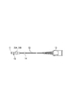
図1は、本実施の形態における温度センサの構成を説明するための図である。
図1に示すように、温度センサ10は、保護管11内に、二つのサーミスタ20A、20Bが収容された構成を有している。
図2に示すように、リード線23、23は、保護管11の開口端側から外部に導出し、温度センサ10のコントローラ(図示無し)に接続するための端子ハウジング13が、リード線23,23の他端に設けられている。ここで、二つのサーミスタ20A、20Bのリード線23、23は、環状の保護チューブ14や束線バンドによって束ねられており、これらリード線23、23が裂けて分離し、保護管11内の素子本体21等に負担が掛かるのを回避するとともに、内部への水分侵入によるセンサ異常の回避や性能低下を防止している。
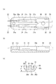
そして、保護管11内に、エポキシ樹脂等の未硬化状態の充填剤60を所定量入れておく。この状態で、サーミスタ20A、20Bおよびホルダー30を保護管11内に挿入する。すると、未硬化状態の充填剤60が、保護管11の内周面と、サーミスタ20A、20Bおよびホルダー30との間の空間40、50を通ってせり上がってくる。そして、充填剤60が固化することで、サーミスタ20A、20Bおよびホルダー30が保護管11に固定される。
また、保護管11の内周面と平面部30b、側面部30cとの間の空間40、50を通して充填剤60が保護管11内で流動できるので、サーミスタ20A、20Bを保護管11内に挿入する際に、サーミスタ20A、20Bを保護管11の奧までスムーズに入れることができる。
Claims (4)
- 一端側が閉塞され、他端側が開口した有底筒状の保護管と、
前記保護管内の前記一端側に配置された二つのサーミスタと、
二つの前記サーミスタのそれぞれの両極に接続された配線と、
前記保護管内で、前記配線のそれぞれに一端が接続され、他端が前記保護管外に導出されたリード線と、
前記保護管内で、前記配線と前記リード線との接続部を保持する絶縁性材料からなるホルダーと、を備え、
前記ホルダーは、
外周面に平面部を有し、当該ホルダーを前記保護管内に挿入したときに、前記保護管の内周面と前記平面部との間に空隙が形成され、かつ、
二つの前記サーミスタのそれぞれに対応して設けられ、
前記サーミスタのそれぞれに接続された二本の前記配線と、当該二本の前記配線に接続される二本の前記リード線との接続部を保持するとともに、線間の絶縁を図り、
二本の前記配線と、当該二本の前記配線に接続される二本の前記リード線とを収容する溝が形成され、前記溝が開口した側の面を、前記保護管内で他の前記ホルダーに対向させて設けられることを特徴とする温度センサ。 - 前記保護管内に絶縁性を有した硬化性材料からなる充填剤が充填され、前記充填剤により、前記保護管内の前記サーミスタ、前記配線、前記リード線、前記ホルダーが固定されていることを特徴とする請求項1に記載の温度センサ。
- 二つの前記サーミスタは、前記保護管内で、当該保護管の径方向に並列に配置され、前記サーミスタと前記保護管の内周面とが近接していることを特徴とする請求項1または2のいずれかに記載の温度センサ。
- 二つの前記サーミスタは、同じ特性を有していることを特徴とする請求項1から3のいずれか一項に記載の温度センサ。
Priority Applications (3)
| Application Number | Priority Date | Filing Date | Title |
|---|---|---|---|
| JP2010181536A JP5523982B2 (ja) | 2010-08-16 | 2010-08-16 | 温度センサ |
| US13/817,474 US9322718B2 (en) | 2010-08-16 | 2011-07-14 | Temperature sensor |
| PCT/JP2011/004024 WO2012023232A1 (ja) | 2010-08-16 | 2011-07-14 | 温度センサ |
Applications Claiming Priority (1)
| Application Number | Priority Date | Filing Date | Title |
|---|---|---|---|
| JP2010181536A JP5523982B2 (ja) | 2010-08-16 | 2010-08-16 | 温度センサ |
Publications (3)
| Publication Number | Publication Date |
|---|---|
| JP2012042238A JP2012042238A (ja) | 2012-03-01 |
| JP2012042238A5 JP2012042238A5 (ja) | 2013-06-20 |
| JP5523982B2 true JP5523982B2 (ja) | 2014-06-18 |
Family
ID=45604903
Family Applications (1)
| Application Number | Title | Priority Date | Filing Date |
|---|---|---|---|
| JP2010181536A Active JP5523982B2 (ja) | 2010-08-16 | 2010-08-16 | 温度センサ |
Country Status (3)
| Country | Link |
|---|---|
| US (1) | US9322718B2 (ja) |
| JP (1) | JP5523982B2 (ja) |
| WO (1) | WO2012023232A1 (ja) |
Families Citing this family (10)
| Publication number | Priority date | Publication date | Assignee | Title |
|---|---|---|---|---|
| JP5381943B2 (ja) * | 2010-09-17 | 2014-01-08 | オムロンヘルスケア株式会社 | 電子体温計およびその製造方法 |
| US20140028434A1 (en) * | 2012-07-25 | 2014-01-30 | Polestar Electric Industries Co., Ltd. | Self-recovery circuit breaker |
| JP6279284B2 (ja) * | 2013-10-17 | 2018-02-14 | 株式会社芝浦電子 | 温度センサ |
| EP3551978B1 (en) * | 2016-12-07 | 2022-01-26 | Fisher&Paykel Healthcare Limited | Sensing arrangements for medical devices |
| US11105688B2 (en) * | 2017-01-16 | 2021-08-31 | Shibaura Electronics Co., Ltd. | Attaching a thermistor on a case |
| DE102018102709A1 (de) * | 2018-02-07 | 2019-08-08 | Tdk Electronics Ag | Temperatursensor und ein Verfahren zur Herstellung des Temperatursensors |
| CN109073480B (zh) * | 2018-02-13 | 2022-07-05 | 株式会社芝浦电子 | 温度传感器、传感器元件以及温度传感器的制造方法 |
| US11525739B2 (en) * | 2018-05-08 | 2022-12-13 | Texas Instruments Incorporated | Thermistor die-based thermal probe |
| JP2020024148A (ja) * | 2018-08-08 | 2020-02-13 | パナソニックIpマネジメント株式会社 | 温度センサ |
| DE102018133502A1 (de) * | 2018-12-21 | 2020-06-25 | Tdk Electronics Ag | Temperatursensorvorrichtung für hohe Temperaturen |
Family Cites Families (21)
| Publication number | Priority date | Publication date | Assignee | Title |
|---|---|---|---|---|
| GB8531177D0 (en) * | 1985-12-18 | 1986-01-29 | Bicc Plc | Temperature monitoring device |
| JP3161240B2 (ja) | 1994-08-30 | 2001-04-25 | 三菱マテリアル株式会社 | サーミスタセンサ |
| JPH09250952A (ja) * | 1996-01-08 | 1997-09-22 | Matsushita Electric Ind Co Ltd | 温度検出装置とそれを用いた自動車 |
| JP3028906U (ja) * | 1996-03-12 | 1996-09-17 | 株式会社芝浦電子製作所 | サーミスタ温度センサ |
| JPH10221179A (ja) | 1997-01-31 | 1998-08-21 | Ooizumi Seisakusho:Kk | 温度センサ |
| JP3485027B2 (ja) * | 1998-07-24 | 2004-01-13 | 株式会社デンソー | 温度センサおよびその製造方法 |
| JP2000111414A (ja) * | 1998-10-09 | 2000-04-21 | Hyakuryaku Kigyo Kofun Yugenkoshi | 医療体温計 |
| JP4016627B2 (ja) * | 2000-11-22 | 2007-12-05 | 株式会社デンソー | 温度センサ |
| JP2002267547A (ja) * | 2001-03-14 | 2002-09-18 | Denso Corp | 温度センサ |
| JP2002289407A (ja) | 2001-03-23 | 2002-10-04 | Denso Corp | 温度センサおよびその製造方法 |
| JP3788363B2 (ja) * | 2001-03-23 | 2006-06-21 | 株式会社デンソー | 温度センサ |
| JP2003302292A (ja) * | 2002-02-07 | 2003-10-24 | Denso Corp | センサおよびその製造方法 |
| JP2003234203A (ja) * | 2002-02-07 | 2003-08-22 | Denso Corp | 温度センサの製造方法 |
| JP2003240642A (ja) | 2002-02-15 | 2003-08-27 | Ishizuka Electronics Corp | 温度センサ |
| JP4620400B2 (ja) * | 2004-07-16 | 2011-01-26 | 日本特殊陶業株式会社 | 温度センサ、温度センサの製造方法 |
| JP2006258520A (ja) * | 2005-03-16 | 2006-09-28 | Ishizuka Electronics Corp | 電子体温計用プローブ |
| JP2007212195A (ja) * | 2006-02-07 | 2007-08-23 | Denso Corp | 温度センサ及びその製造方法 |
| US20090059998A1 (en) * | 2007-08-27 | 2009-03-05 | Billy Hou | Multiple temperature resistance characteristic sensing cable and its sensor |
| JP4994329B2 (ja) * | 2008-08-26 | 2012-08-08 | リンナイ株式会社 | 給湯装置 |
| DE102008064360B3 (de) * | 2008-12-22 | 2010-08-19 | Abb Technology Ag | Anordnung von Sensorelementen zur Temperaturmessung |
| JP6278957B2 (ja) * | 2012-05-14 | 2018-02-14 | 深▲セン▼市敏▲傑▼▲電▼子科技有限公司 | 表面温度計測の温度センサー |
-
2010
- 2010-08-16 JP JP2010181536A patent/JP5523982B2/ja active Active
-
2011
- 2011-07-14 US US13/817,474 patent/US9322718B2/en active Active
- 2011-07-14 WO PCT/JP2011/004024 patent/WO2012023232A1/ja active Application Filing
Also Published As
| Publication number | Publication date |
|---|---|
| WO2012023232A1 (ja) | 2012-02-23 |
| US20130208765A1 (en) | 2013-08-15 |
| JP2012042238A (ja) | 2012-03-01 |
| US9322718B2 (en) | 2016-04-26 |
Similar Documents
| Publication | Publication Date | Title |
|---|---|---|
| JP5523982B2 (ja) | 温度センサ | |
| JP2015512513A (ja) | 温度センサ | |
| JP4940938B2 (ja) | 熱式質量流量計 | |
| US11852271B2 (en) | Modular heater systems | |
| EP3264056B1 (en) | Temperature sensor | |
| JP6440589B2 (ja) | 温度検出装置 | |
| JP2012042238A5 (ja) | ||
| JP2008224553A (ja) | サーミスタ取付体 | |
| US6782761B2 (en) | Ultrasonic flow meter | |
| US7789555B2 (en) | Temperature sensor | |
| CN109029753A (zh) | 温度传感器以及电池组 | |
| KR20180071966A (ko) | 고온 배기 센서 | |
| KR101597302B1 (ko) | 온도센서 및 그 제조방법 | |
| EP1990619A2 (en) | Mineral oxide thermocouple temperature probe and production process thereof | |
| KR101514048B1 (ko) | 열전대 온도 측정 장치 | |
| JPS62278421A (ja) | 温度センサの製造方法 | |
| JP2006258724A (ja) | 耐振型温度センサ | |
| JP6589498B2 (ja) | 温度センサ | |
| JP4662307B2 (ja) | ポリイミドをコーティングしたシース熱電対 | |
| KR102481783B1 (ko) | 파이프 온도 측정 센서의 보호 커버 | |
| JP4853782B2 (ja) | 温度センサ | |
| JP5522129B2 (ja) | 圧力温度複合センサ装置 | |
| JP2015215256A (ja) | 接触式温度計 | |
| KR20190099544A (ko) | 파이프 온도 측정 센서의 보호 커버 | |
| JP5871717B2 (ja) | シース型熱電対アダプタ |
Legal Events
| Date | Code | Title | Description |
|---|---|---|---|
| A521 | Request for written amendment filed |
Free format text: JAPANESE INTERMEDIATE CODE: A523 Effective date: 20130426 |
|
| A621 | Written request for application examination |
Free format text: JAPANESE INTERMEDIATE CODE: A621 Effective date: 20130426 |
|
| TRDD | Decision of grant or rejection written | ||
| A01 | Written decision to grant a patent or to grant a registration (utility model) |
Free format text: JAPANESE INTERMEDIATE CODE: A01 Effective date: 20140402 |
|
| A61 | First payment of annual fees (during grant procedure) |
Free format text: JAPANESE INTERMEDIATE CODE: A61 Effective date: 20140409 |
|
| R150 | Certificate of patent or registration of utility model |
Ref document number: 5523982 Country of ref document: JP Free format text: JAPANESE INTERMEDIATE CODE: R150 |
|
| R250 | Receipt of annual fees |
Free format text: JAPANESE INTERMEDIATE CODE: R250 |
|
| R250 | Receipt of annual fees |
Free format text: JAPANESE INTERMEDIATE CODE: R250 |
|
| R250 | Receipt of annual fees |
Free format text: JAPANESE INTERMEDIATE CODE: R250 |
|
| R250 | Receipt of annual fees |
Free format text: JAPANESE INTERMEDIATE CODE: R250 |
|
| R250 | Receipt of annual fees |
Free format text: JAPANESE INTERMEDIATE CODE: R250 |
|
| R250 | Receipt of annual fees |
Free format text: JAPANESE INTERMEDIATE CODE: R250 |
|
| R250 | Receipt of annual fees |
Free format text: JAPANESE INTERMEDIATE CODE: R250 |
|
| R250 | Receipt of annual fees |
Free format text: JAPANESE INTERMEDIATE CODE: R250 |