WO2018097255A1 - 液体吐出ヘッドおよびそれを用いた記録装置 - Google Patents
液体吐出ヘッドおよびそれを用いた記録装置 Download PDFInfo
- Publication number
- WO2018097255A1 WO2018097255A1 PCT/JP2017/042245 JP2017042245W WO2018097255A1 WO 2018097255 A1 WO2018097255 A1 WO 2018097255A1 JP 2017042245 W JP2017042245 W JP 2017042245W WO 2018097255 A1 WO2018097255 A1 WO 2018097255A1
- Authority
- WO
- WIPO (PCT)
- Prior art keywords
- drive
- signal
- circuit
- drive circuit
- drive circuits
- Prior art date
Links
Images


Classifications
-
- B—PERFORMING OPERATIONS; TRANSPORTING
- B41—PRINTING; LINING MACHINES; TYPEWRITERS; STAMPS
- B41J—TYPEWRITERS; SELECTIVE PRINTING MECHANISMS, i.e. MECHANISMS PRINTING OTHERWISE THAN FROM A FORME; CORRECTION OF TYPOGRAPHICAL ERRORS
- B41J2/00—Typewriters or selective printing mechanisms characterised by the printing or marking process for which they are designed
- B41J2/005—Typewriters or selective printing mechanisms characterised by the printing or marking process for which they are designed characterised by bringing liquid or particles selectively into contact with a printing material
- B41J2/01—Ink jet
- B41J2/135—Nozzles
- B41J2/14—Structure thereof only for on-demand ink jet heads
- B41J2/14201—Structure of print heads with piezoelectric elements
- B41J2/14209—Structure of print heads with piezoelectric elements of finger type, chamber walls consisting integrally of piezoelectric material
-
- B—PERFORMING OPERATIONS; TRANSPORTING
- B41—PRINTING; LINING MACHINES; TYPEWRITERS; STAMPS
- B41J—TYPEWRITERS; SELECTIVE PRINTING MECHANISMS, i.e. MECHANISMS PRINTING OTHERWISE THAN FROM A FORME; CORRECTION OF TYPOGRAPHICAL ERRORS
- B41J2/00—Typewriters or selective printing mechanisms characterised by the printing or marking process for which they are designed
- B41J2/005—Typewriters or selective printing mechanisms characterised by the printing or marking process for which they are designed characterised by bringing liquid or particles selectively into contact with a printing material
- B41J2/01—Ink jet
- B41J2/015—Ink jet characterised by the jet generation process
- B41J2/04—Ink jet characterised by the jet generation process generating single droplets or particles on demand
- B41J2/045—Ink jet characterised by the jet generation process generating single droplets or particles on demand by pressure, e.g. electromechanical transducers
- B41J2/04501—Control methods or devices therefor, e.g. driver circuits, control circuits
- B41J2/04581—Control methods or devices therefor, e.g. driver circuits, control circuits controlling heads based on piezoelectric elements
-
- B—PERFORMING OPERATIONS; TRANSPORTING
- B41—PRINTING; LINING MACHINES; TYPEWRITERS; STAMPS
- B41J—TYPEWRITERS; SELECTIVE PRINTING MECHANISMS, i.e. MECHANISMS PRINTING OTHERWISE THAN FROM A FORME; CORRECTION OF TYPOGRAPHICAL ERRORS
- B41J2/00—Typewriters or selective printing mechanisms characterised by the printing or marking process for which they are designed
- B41J2/005—Typewriters or selective printing mechanisms characterised by the printing or marking process for which they are designed characterised by bringing liquid or particles selectively into contact with a printing material
- B41J2/01—Ink jet
- B41J2/015—Ink jet characterised by the jet generation process
- B41J2/04—Ink jet characterised by the jet generation process generating single droplets or particles on demand
- B41J2/045—Ink jet characterised by the jet generation process generating single droplets or particles on demand by pressure, e.g. electromechanical transducers
- B41J2/04501—Control methods or devices therefor, e.g. driver circuits, control circuits
- B41J2/04593—Dot-size modulation by changing the size of the drop
-
- B—PERFORMING OPERATIONS; TRANSPORTING
- B41—PRINTING; LINING MACHINES; TYPEWRITERS; STAMPS
- B41J—TYPEWRITERS; SELECTIVE PRINTING MECHANISMS, i.e. MECHANISMS PRINTING OTHERWISE THAN FROM A FORME; CORRECTION OF TYPOGRAPHICAL ERRORS
- B41J2/00—Typewriters or selective printing mechanisms characterised by the printing or marking process for which they are designed
- B41J2/005—Typewriters or selective printing mechanisms characterised by the printing or marking process for which they are designed characterised by bringing liquid or particles selectively into contact with a printing material
- B41J2/01—Ink jet
- B41J2/015—Ink jet characterised by the jet generation process
- B41J2/04—Ink jet characterised by the jet generation process generating single droplets or particles on demand
- B41J2/045—Ink jet characterised by the jet generation process generating single droplets or particles on demand by pressure, e.g. electromechanical transducers
- B41J2/04501—Control methods or devices therefor, e.g. driver circuits, control circuits
- B41J2/04595—Dot-size modulation by changing the number of drops per dot
-
- B—PERFORMING OPERATIONS; TRANSPORTING
- B41—PRINTING; LINING MACHINES; TYPEWRITERS; STAMPS
- B41J—TYPEWRITERS; SELECTIVE PRINTING MECHANISMS, i.e. MECHANISMS PRINTING OTHERWISE THAN FROM A FORME; CORRECTION OF TYPOGRAPHICAL ERRORS
- B41J2/00—Typewriters or selective printing mechanisms characterised by the printing or marking process for which they are designed
- B41J2/005—Typewriters or selective printing mechanisms characterised by the printing or marking process for which they are designed characterised by bringing liquid or particles selectively into contact with a printing material
- B41J2/01—Ink jet
- B41J2/21—Ink jet for multi-colour printing
- B41J2/2121—Ink jet for multi-colour printing characterised by dot size, e.g. combinations of printed dots of different diameter
- B41J2/2128—Ink jet for multi-colour printing characterised by dot size, e.g. combinations of printed dots of different diameter by means of energy modulation
-
- B—PERFORMING OPERATIONS; TRANSPORTING
- B41—PRINTING; LINING MACHINES; TYPEWRITERS; STAMPS
- B41J—TYPEWRITERS; SELECTIVE PRINTING MECHANISMS, i.e. MECHANISMS PRINTING OTHERWISE THAN FROM A FORME; CORRECTION OF TYPOGRAPHICAL ERRORS
- B41J2/00—Typewriters or selective printing mechanisms characterised by the printing or marking process for which they are designed
- B41J2/005—Typewriters or selective printing mechanisms characterised by the printing or marking process for which they are designed characterised by bringing liquid or particles selectively into contact with a printing material
- B41J2/01—Ink jet
- B41J2/135—Nozzles
- B41J2/14—Structure thereof only for on-demand ink jet heads
- B41J2002/14419—Manifold
-
- B—PERFORMING OPERATIONS; TRANSPORTING
- B41—PRINTING; LINING MACHINES; TYPEWRITERS; STAMPS
- B41J—TYPEWRITERS; SELECTIVE PRINTING MECHANISMS, i.e. MECHANISMS PRINTING OTHERWISE THAN FROM A FORME; CORRECTION OF TYPOGRAPHICAL ERRORS
- B41J2/00—Typewriters or selective printing mechanisms characterised by the printing or marking process for which they are designed
- B41J2/005—Typewriters or selective printing mechanisms characterised by the printing or marking process for which they are designed characterised by bringing liquid or particles selectively into contact with a printing material
- B41J2/01—Ink jet
- B41J2/135—Nozzles
- B41J2/14—Structure thereof only for on-demand ink jet heads
- B41J2002/14459—Matrix arrangement of the pressure chambers
-
- B—PERFORMING OPERATIONS; TRANSPORTING
- B41—PRINTING; LINING MACHINES; TYPEWRITERS; STAMPS
- B41J—TYPEWRITERS; SELECTIVE PRINTING MECHANISMS, i.e. MECHANISMS PRINTING OTHERWISE THAN FROM A FORME; CORRECTION OF TYPOGRAPHICAL ERRORS
- B41J2202/00—Embodiments of or processes related to ink-jet or thermal heads
- B41J2202/01—Embodiments of or processes related to ink-jet heads
- B41J2202/20—Modules
-
- B—PERFORMING OPERATIONS; TRANSPORTING
- B41—PRINTING; LINING MACHINES; TYPEWRITERS; STAMPS
- B41J—TYPEWRITERS; SELECTIVE PRINTING MECHANISMS, i.e. MECHANISMS PRINTING OTHERWISE THAN FROM A FORME; CORRECTION OF TYPOGRAPHICAL ERRORS
- B41J2202/00—Embodiments of or processes related to ink-jet or thermal heads
- B41J2202/01—Embodiments of or processes related to ink-jet heads
- B41J2202/21—Line printing
Definitions
- the present disclosure relates to a liquid discharge head and a recording apparatus using the same.
- an ink jet head that performs various types of printing by discharging a liquid onto a recording medium is known as a liquid discharge head.
- a liquid ejection head the liquid is ejected from a plurality of ejection holes provided corresponding to each of the pressure units by pressurizing the liquid with the plurality of pressure units.
- the liquid discharge head includes a plurality of discharge holes, a plurality of pressurizing units, a plurality of drive circuits, a switch circuit, a first control circuit, and a second control circuit.
- the plurality of pressurizing units pressurize the liquid and discharge the liquid from the discharge holes.
- the drive circuit outputs a drive signal for driving the plurality of pressure units.
- the switch circuit switches connection between the plurality of pressure units and the plurality of drive circuits.
- the first control circuit controls the plurality of drive circuits.
- the second control circuit controls the switch circuit.
- the liquid ejection head ejects, as the driving signal, a first signal for ejecting a droplet forming a first size pixel and a droplet forming a second size pixel different from the first size. And a plurality of types of signals including at least a second signal.
- the first control circuit controls the plurality of drive circuits so that different types of the drive signals are output from the different drive circuits.
- Each of the plurality of pressure units is connected to the driving circuit that outputs the first signal when ejecting a droplet forming the first size pixel, thereby forming the second size pixel.
- the second control circuit controls the switch circuit so as to be connected to the drive circuit outputting the second signal when ejecting a droplet.
- the first control circuit controls the plurality of drive circuits such that the drive circuit in charge of outputting the first signal is switched among the plurality of drive circuits.
- the recording apparatus includes the liquid discharge head and a transport unit that transports a recording medium to the liquid discharge head.
- FIG. 1A is a side view schematically illustrating an example of a configuration of a recording apparatus including a liquid ejection head according to the present disclosure.
- FIG. 1B is a plan view schematically illustrating an example of a configuration of a recording apparatus including the liquid ejection head of the present disclosure.
- FIG. 2 is a plan view of a head body which is a main part of the liquid discharge head of FIG.
- FIG. 3 is an enlarged view of a region A surrounded by an alternate long and short dash line in FIG. 2, and a part of the flow paths is omitted for explanation.
- FIG. 4 is an enlarged view of a region A surrounded by a one-dot chain line in FIG. 2, and a part of the flow paths is omitted for explanation.
- FIG. 1A is a side view schematically illustrating an example of a configuration of a recording apparatus including a liquid ejection head according to the present disclosure.
- FIG. 1B is a plan view schematically illustrating an example of
- FIG. 5 is a longitudinal sectional view taken along line VV in FIG.
- FIG. 6 is a diagram illustrating an example of a configuration of a head control system in the liquid ejection head according to the present disclosure.
- FIG. 7 is a diagram illustrating an example of rotation of the drive circuit in the liquid discharge head according to the present disclosure.
- FIG. 8 is a plan view schematically showing an example of the arrangement of drive circuits on the liquid ejection head of the present disclosure.
- FIG. 9 is a plan view schematically illustrating another example of the arrangement of the drive circuits on the liquid ejection head according to the present disclosure.
- FIG. 10 is a diagram illustrating a signal output from each drive circuit at each time when the drive circuit illustrated in FIG. 7 is rotated.
- a plurality of types of drive signals corresponding to the sizes (for example, small pixels, medium pixels, and large pixels) of pixels formed on a recording medium may be generated by different circuits. Conceivable.
- multiple types of drive signals are generated by different circuits, there is a difference in the amount of heat generated by the circuits that generate the drive signals, depending on the number of pressure units to which the drive signals are sent. (For example, when printing a solid pattern, the number of pressure units to which drive signals corresponding to large pixels are sent increases significantly, and the amount of heat generated by the circuit that generates the drive signals corresponding to large pixels) Increases significantly).
- the liquid discharge head according to the present disclosure can reduce an excessive temperature rise in a specific circuit, and can reduce a temperature difference between a plurality of circuits. This can reduce the occurrence of circuit malfunction due to temperature rise.
- the liquid ejection head of the present disclosure and a recording apparatus using the liquid ejection head will be described in detail.
- FIG. 1A and 1B are schematic drawings of a color inkjet printer 1 (hereinafter sometimes simply referred to as a printer) that is an example of a recording apparatus including a liquid ejection head according to the present disclosure.
- 1A is a side view
- FIG. 1B is a plan view.
- the printer 1 moves the print paper P relative to the liquid ejection head 2 by transporting the print paper P as a recording medium from the guide roller 82 ⁇ / b> A to the transport roller 82 ⁇ / b> B.
- the printer 1 controls the liquid ejection head 2 by the control unit 88 to eject liquid from the liquid ejection head 2 based on image and character data, and cause droplets to land on the printing paper P. In this way, the printer 1 performs recording such as printing on the printing paper P.
- the liquid discharge head 2 is fixed to the printer 1, and the printer 1 is a so-called line printer, but is not limited to this.
- a so-called serial printer that alternately moves the liquid ejection head 2 by reciprocating in the direction intersecting the conveyance direction of the printing paper P, for example, in a substantially orthogonal direction, and the conveyance of the printing paper P may be used. good.
- the printer 1 has a flat head mounting frame 70 (hereinafter sometimes simply referred to as a frame) fixed so as to be substantially parallel to the printing paper P.
- the frame 70 is provided with 20 holes (not shown), and the 20 liquid discharge heads 2 are mounted in the respective hole portions, and the portion of the liquid discharge head 2 that discharges the liquid is the printing paper P. It has come to face.
- the distance between the liquid ejection head 2 and the printing paper P is, for example, about 0.5 to 20 mm.
- FIG. 1 shows an example in which one head group 72 is configured by five liquid ejection heads 2 out of 20 liquid ejection heads 2, and the printer 1 has four head groups 72.
- the liquid discharge head 2 has a long and narrow shape in the direction from the front to the back in FIG. 1A and in the vertical direction in FIG. 1B. This long direction is sometimes called the longitudinal direction.
- the three liquid ejection heads 2 are arranged along a direction that intersects the transport direction of the printing paper P, for example, a direction that is substantially orthogonal.
- the other two liquid discharge heads 2 are arranged one by one between the three liquid discharge heads 2 at positions shifted along the transport direction.
- the liquid discharge heads 2 are arranged so that the printable range of each liquid discharge head 2 is connected in the width direction of the print paper P (in the direction intersecting the conveyance direction of the print paper P) or the ends overlap. Thus, printing without gaps in the width direction of the printing paper P is possible.
- the four head groups 72 are arranged along the conveyance direction of the printing paper P.
- a liquid, for example, ink is supplied to each liquid ejection head 2 from a liquid tank (not shown).
- the liquid discharge heads 2 belonging to one head group 72 are supplied with the same color ink, and the four head groups 72 can print four color inks.
- the colors of ink ejected from each head group 72 are, for example, magenta (M), yellow (Y), cyan (C), and black (K).
- M magenta
- Y yellow
- C cyan
- K black
- a color image can be printed by printing such ink under the control of the control unit 88.
- the number of the liquid discharge heads 2 mounted on the printer 1 may be one as long as it is monochrome printing and a range that can be printed by one liquid discharge head 2 is printed.
- the number of liquid ejection heads 2 included in the head group 72 and the number of head groups 72 can be changed as appropriate according to the printing target and printing conditions. For example, the number of head groups 72 may be increased in order to perform multicolor printing. Also, if a plurality of head groups 72 that print in the same color are arranged and printed alternately in the transport direction, the transport speed can be increased even if the liquid ejection heads 2 having the same performance are used. Thereby, the printing area per time can be increased. Alternatively, a plurality of head groups 72 for printing in the same color may be prepared and arranged so as to be shifted in a direction crossing the transport direction, so that the resolution in the width direction of the print paper P may be increased.
- a liquid such as a coating agent may be printed for surface treatment of the printing paper P.
- the printer 1 performs printing on the printing paper P that is a recording medium.
- the printing paper P is wound around the paper feed roller 80A, passes between the two guide rollers 82A, passes under the liquid ejection head 2 mounted on the frame 70, and then 2 It passes between the two conveying rollers 82B and is finally collected by the collecting roller 80B.
- the printing paper P is transported at a constant speed by rotating the transport roller 82 ⁇ / b> B and printed by the liquid ejection head 2.
- the collection roller 80B winds up the printing paper P sent out from the conveyance roller 82B.
- the paper feed roller 80A, the guide roller 82A, the transport roller 82B, and the collection roller 80B constitute a transport unit that transports the printing paper P to the liquid ejection head 2.
- the conveyance speed is, for example, 75 m / min.
- Each roller may be controlled by the controller 88 or may be manually operated by a person.
- the recording medium may be a roll-like cloth other than the printing paper P. Further, instead of directly transporting the printing paper P, the printer 1 may directly transport the transport belt and transport the recording medium placed on the transport belt. By doing so, sheets, cut cloth, wood, tiles and the like can be used as the recording medium. Furthermore, a wiring pattern of an electronic device may be printed by discharging a liquid containing conductive particles from the liquid discharge head 2. Still further, the chemical may be produced by discharging a predetermined amount of liquid chemical agent or liquid containing the chemical agent from the liquid discharge head 2 toward the reaction container or the like and reacting.
- a position sensor, a speed sensor, a temperature sensor, and the like may be attached to the printer 1, and the control unit 88 may control each part of the printer 1 according to the state of each part of the printer 1 that can be understood from information from each sensor.
- the temperature of the liquid discharge head 2, the temperature of the liquid in the liquid tank, the pressure applied by the liquid in the liquid tank to the liquid discharge head 2, etc. affect the discharge characteristics such as the discharge amount and discharge speed of the discharged liquid.
- the drive signal for ejecting the liquid may be changed according to the information.
- the recording apparatus may include a liquid discharge head and a transport unit that transports a recording medium to the liquid discharge head, and other configurations are not limited. Further, the configuration of the transport unit is not limited to the configuration shown in the present embodiment.
- FIG. 2 is a plan view showing a head main body 2a which is a main part of the liquid ejection head 2 shown in FIG.
- FIG. 3 is an enlarged plan view of a region surrounded by a one-dot chain line in FIG. 2, and is a part of the head main body 2a.
- FIG. 4 is an enlarged plan view at the same position as FIG. 3, and a part of the flow path different from FIG. 3 is omitted.
- FIG. 5 is a longitudinal sectional view taken along line VV in FIG.
- the pressurizing chamber 10 the squeezing 6, the discharge holes 8, and the like that are to be drawn by broken lines below the piezoelectric actuator substrate 21 are drawn by solid lines.
- the liquid discharge head 2 may include a reservoir for supplying liquid to the head main body 2a and a housing in addition to the head main body 2a.
- the head body 2a includes a flow path member 4 and a piezoelectric actuator substrate 21 in which the pressurizing unit 30 is built.
- the flow path member 4 constituting the head body 2a includes a manifold 5 which is a common flow path, a plurality of pressurizing chambers 10 connected to the manifold 5, and a plurality of discharge holes respectively connected to the plurality of pressurizing chambers 10. 8 and.
- the pressurizing chamber 10 is opened on the upper surface of the flow path member 4, and the upper surface of the flow path member 4 is a pressurizing chamber surface 4-2.
- the upper surface of the flow path member 4 has an opening 5a connected to the manifold 5, and liquid is supplied from the opening 5a.
- the piezoelectric actuator substrate 21 including the pressurizing unit 30 is bonded to the upper surface of the flow path member 4, and each pressurizing unit 30 is disposed on the pressurizing chamber 10.
- the piezoelectric actuator substrate 21 is connected to a signal transmission unit 60 that supplies a signal to each pressure unit 30.
- the outline of the vicinity of the signal transmission unit 60 connected to the piezoelectric actuator substrate 21 is indicated by a dotted line so that the two signal transmission units 60 are connected to the piezoelectric actuator substrate 21.
- the electrodes formed on the signal transmission unit 60 that are electrically connected to the piezoelectric actuator substrate 21 are arranged in a rectangular shape at the end of the signal transmission unit 60.
- the two signal transmission parts 60 are connected so that each end comes to the center part in the short direction of the piezoelectric actuator substrate 21.
- the head body 2 a has one plate-shaped flow path member 4 and one piezoelectric actuator substrate 21 including a pressurizing unit 30 bonded on the flow path member 4.
- the planar shape of the piezoelectric actuator substrate 21 is rectangular, and is arranged on the upper surface of the flow path member 4 so that the long side of the rectangle is along the longitudinal direction of the flow path member 4.
- the manifold 5 has an elongated shape extending from one end side in the longitudinal direction of the flow path member 4 to the other end side, and the opening of the manifold 5 that opens to the upper surface of the flow path member 4 at both ends thereof. 5a is formed.
- the manifold 5 is partitioned by a partition wall 15 provided at an interval in the short direction at least in the central portion in the longitudinal direction, which is an area connected to the pressurizing chamber 10.
- the partition wall 15 has the same height as the manifold 5 in the central portion in the longitudinal direction, which is a region connected to the pressurizing chamber 10, and completely separates the manifold 5 into a plurality of portions. By doing so, it is possible to provide the discharge hole 8 and the flow path connected from the discharge hole 8 to the pressurizing chamber 10 so as to overlap with the partition wall 15 in a plan view.
- the manifold 5 that is divided into a plurality of parts is sometimes referred to as a sub-manifold 5b.
- two manifolds 5 are provided independently, and openings 5a are provided at both ends.
- One manifold 5 is provided with seven partition walls 15 and divided into eight sub-manifolds 5b.
- the width of the sub-manifold 5b is larger than the width of the partition wall 15, so that a large amount of liquid can flow through the sub-manifold 5b.
- the flow path member 4 is formed by two-dimensionally expanding a plurality of pressurizing chambers 10.
- the pressurizing chamber 10 is a hollow region having a substantially rhombic or elliptical planar shape with rounded corners.
- the pressurizing chamber 10 is connected to one sub-manifold 5b through a throttle 6.
- two pressurizing chamber rows 11, which are rows of pressurizing chambers 10 connected to the sub-manifold 5b, are provided on each side of the sub-manifold 5b, for a total of two rows. Yes.
- 16 rows of pressurizing chambers 11 are provided for one manifold 5, and 32 heads of pressurizing chambers 11 are provided in the entire head body 2a.
- the intervals in the longitudinal direction of the pressurizing chambers 10 in the respective pressurizing chamber rows 11 are the same, for example, 37.5 dpi.
- a column of dummy pressurizing chambers 16 is provided at the end of each pressurizing chamber row 11.
- the dummy pressurizing chambers 16 in the dummy pressurizing chamber row are connected to the manifold 5 but are not connected to the discharge holes 8. Further, one dummy pressurizing chamber row in which dummy pressurizing chambers 16 are arranged in a straight line is provided outside the 32 pressurizing chamber rows 11. The dummy pressurizing chamber 16 in this dummy pressurizing chamber row is not connected to either the manifold 5 or the discharge hole 8.
- the structure (rigidity) around the pressurizing chamber 10 one inner side from the end is close to the structure (rigidity) of the other pressurizing chambers 10, so that the difference in liquid ejection characteristics can be reduced. Less.
- the dummy pressurizing chambers are provided at both ends in the length direction. Since the influence in the width direction is relatively small, the width direction is provided only near the end of the head main body 21a. Thereby, the width
- the pressurizing chambers 10 connected to the single manifold 5 are arranged in a lattice form having rows and columns along each outer side of the rectangular piezoelectric actuator substrate 21.
- the individual electrodes 25 formed on the pressurizing chamber 10 are arranged at equal distances from the outer side of the piezoelectric actuator substrate 21. Therefore, when forming the individual electrodes 25, the piezoelectric actuator substrate is formed. 21 can be hardly deformed.
- the piezoelectric actuator substrate 21 and the flow path member 4 are joined, if this deformation is large, stress is applied to the pressurizing portion 30 near the outer side, and there is a risk that the displacement characteristics may vary, but the deformation should be reduced. Therefore, the variation can be reduced.
- the dummy pressurizing chamber row of the dummy pressurizing chamber 16 is provided outside the pressurizing chamber row 11 closest to the outer side, the influence of deformation can be made less susceptible.
- the pressurizing chambers 10 belonging to the pressurizing chamber row 11 are arranged at equal intervals, and the individual electrodes 25 corresponding to the pressurizing chamber rows 11 are also arranged at equal intervals.
- the pressurizing chamber rows 11 are arranged at equal intervals in the short direction, and the rows of the individual electrodes 25 corresponding to the pressurizing chamber rows 11 are also arranged at equal intervals in the short direction. Thereby, it is possible to eliminate a portion where the influence of the crosstalk becomes particularly large.
- the pressurizing chambers 10 are arranged in a lattice pattern, but the pressurizing chambers 10 of adjacent pressurizing chamber rows 11 may be arranged in a staggered manner so as to be positioned between each other. In this way, since the distance between the pressurizing chambers 10 belonging to the adjacent pressurizing chamber row 11 becomes longer, crosstalk can be further suppressed.
- the pressurizing chamber 10 belonging to one pressurizing chamber row 11 is added to the adjacent pressurizing chamber row 11.
- the pressure chamber 10 and the liquid discharge head 2 are arranged so as not to overlap in the longitudinal direction, crosstalk can be suppressed.
- the width of the liquid discharge head 2 is increased, so that the accuracy of the installation angle of the liquid discharge head 2 relative to the printer 1 and the use of a plurality of liquid discharge heads 2 are increased.
- the influence of the relative position accuracy of the liquid discharge head 2 on the printing result is increased. Therefore, by making the width of the partition wall 15 smaller than that of the sub-manifold 5b, the influence of the accuracy on the printing result can be reduced.
- the pressurizing chamber 10 connected to one sub-manifold 5 b forms two rows of pressurizing chamber rows 11, and the discharge holes 8 connected to the pressurizing chambers 10 belonging to one pressurizing chamber row 11 are One discharge hole row 9 is formed.
- the discharge holes 8 connected to the pressurizing chambers 10 belonging to the two pressurizing chamber rows 11 open to different sides of the sub-manifold 5b.
- two discharge hole rows 9 are provided in the partition wall 15, but the discharge holes 8 belonging to each discharge hole row 9 are connected to the sub-manifold 5 b on the side close to the discharge holes 8 in the pressurizing chamber 10. Are connected through.
- a plurality of pressurizing chambers 10 are connected to one manifold 5 to form a pressurizing chamber group. Since there are two manifolds 5, there are two pressurizing chamber groups. The arrangement of the pressurizing chambers 10 related to ejection in each pressurizing chamber group is the same, and is arranged at a position translated in the short direction. These pressurizing chambers 10 are arranged over almost the entire surface although there are portions where the gaps between the pressurizing chamber groups are slightly wide in the region facing the piezoelectric actuator substrate 21 on the upper surface of the flow path member 4. . That is, the pressurizing chamber group formed by these pressurizing chambers 10 occupies a region having almost the same shape as the piezoelectric actuator substrate 21. Further, the opening of each pressurizing chamber 10 is closed by bonding the piezoelectric actuator substrate 21 to the upper surface of the flow path member 4.
- the flow channel connected to the discharge hole 8 opened in the discharge hole surface 4-1 on the lower surface of the flow channel member 4 extends. .
- This flow path extends in a direction away from the pressurizing chamber 10 in a plan view. More specifically, the pressurizing chamber 10 extends away from the direction along the long diagonal line while being shifted to the left and right with respect to that direction.
- the discharge chambers 8 can be arranged at intervals of 1200 dpi as a whole, while the pressurization chambers 10 are arranged in a lattice pattern in which the intervals within the pressurization chamber rows 11 are 37.5 dpi.
- each manifold 5 is within the range of R of the virtual straight line shown in FIG. That is, 16 discharge holes 8 connected to, and a total of 32 discharge holes 8 are equally spaced by 1200 dpi.
- an image can be formed with a resolution of 1200 dpi in the longitudinal direction as a whole.
- one discharge hole 8 connected to one manifold 5 is equally spaced at 600 dpi within the range of R of the imaginary straight line.
- Individual electrodes 25 are formed at positions facing the pressurizing chambers 10 on the upper surface of the piezoelectric actuator substrate 21.
- the individual electrode 25 includes an individual electrode main body 25a that is slightly smaller than the pressurizing chamber 10 and has a shape substantially similar to the pressurizing chamber 10, and an extraction electrode 25b that is extracted from the individual electrode main body 25a.
- the individual electrode 25 constitutes an individual electrode row and an individual electrode group.
- a common electrode surface electrode 28 is disposed on the upper surface of the piezoelectric actuator substrate 21.
- the common electrode surface electrode 28 and the common electrode 24 are electrically connected through a through conductor (not shown) disposed in the piezoelectric ceramic layer 21b.
- the discharge hole 8 is arranged at a position avoiding the area facing the manifold 5 arranged on the lower surface side of the flow path member 4. Further, the discharge hole 8 is disposed in a region facing the piezoelectric actuator substrate 21 on the lower surface side of the flow path member 4. These discharge holes 8 occupy a region having almost the same shape as the piezoelectric actuator substrate 21 as one group, and the liquid droplets are discharged from the discharge holes 8 by displacing the pressurizing portions 30 of the corresponding piezoelectric actuator substrate 21. Can be discharged.
- the flow path member 4 included in the head main body 2a has a laminated structure in which a plurality of plates are laminated via an adhesive layer. These plates are a cavity plate 4a, an aperture plate 4b, a supply plate 4c, manifold plates 4d to 4i, a cover plate 4j, and a nozzle plate 4l in order from the upper surface of the flow path member 4. A number of holes are formed in these plates. Since the thickness of each plate is about 10 to 300 ⁇ m, the accuracy of hole formation can be increased. The thickness of the flow path member 4 is about 500 ⁇ m to 2 mm. Each plate is aligned and laminated so that these holes communicate with each other to form the individual flow path 12 and the manifold 5.
- the pressurizing chamber 10 is on the upper surface of the flow path member 4, the manifold 5 is on the inner lower surface side, and the discharge holes 8 are on the lower surface. The manifold 5 and the discharge hole 8 are connected via the pressurizing chamber 10.
- the third partial flow path there is a communication hole that constitutes a descender 7 that is a flow path that communicates with the discharge hole 8 from the other end opposite to the end where the throttle 6 of the pressurizing chamber 10 is connected.
- This communication hole is formed in each plate from the base plate 4b (specifically, the outlet of the pressurizing chamber 10) to the nozzle plate 4l (specifically, the discharge hole 8).
- the communication holes are formed in the manifold plates 4c to 4i. Holes are formed in the manifold plates 4c to 4i so that the partition portions that become the partition walls 15 remain so as to constitute the sub-manifold 5b.
- the partition portions of the manifold plates 4c to 4i are connected to the manifold plates 4c to 4i by half-etched support portions (not shown in the drawing).
- the first to fourth partial flow paths are connected to each other to form an individual flow path 12 from the liquid inlet (manifold 5 outlet) to the discharge hole 8 from the manifold 5.
- the liquid supplied to the manifold 5 is discharged from the discharge hole 8 through the following path.
- the manifold 5 reaches the one end of the aperture 6 upward.
- it proceeds horizontally along the extending direction of the restriction 6 and reaches the other end of the restriction 6.
- it reaches one end of the pressurizing chamber 10 upward.
- it progresses horizontally along the extending direction of the pressurizing chamber 10 and reaches the other end of the pressurizing chamber 10.
- the liquid that has entered the descender 7 from the pressurizing chamber 10 moves in the horizontal direction and is mainly directed downward and reaches the discharge hole 8 that is open on the lower surface, and is discharged to the outside.
- the piezoelectric actuator substrate 21 has a laminated structure composed of two piezoelectric ceramic layers 21a and 21b which are piezoelectric bodies. Each of these piezoelectric ceramic layers 21a and 21b has a thickness of about 20 ⁇ m. The thickness from the lower surface of the piezoelectric ceramic layer 21a of the piezoelectric actuator substrate 21 to the upper surface of the piezoelectric ceramic layer 21b is about 40 ⁇ m. Both of the piezoelectric ceramic layers 21 a and 21 b extend so as to straddle the plurality of pressure chambers 10.
- the piezoelectric ceramic layers 21a, 21b may, for example, strength with a dielectric, lead zirconate titanate (PZT), NaNbO 3 system, BaTiO 3 system, (BiNa) NbO 3 system, such as BiNaNb 5 O 15 system Made of ceramic material.
- PZT lead zirconate titanate
- NaNbO 3 system NaNbO 3 system
- BaTiO 3 system BaTiO 3 system
- BiNa NbO 3 system such as BiNaNb 5 O 15 system Made of ceramic material.
- the piezoelectric ceramic layer 21a does not function as a piezoelectric element, but functions as a simple elastic plate. Therefore, instead of the piezoelectric ceramic layer 21a, other ceramic layers or metal plates that are not piezoelectric bodies may be used.
- the piezoelectric actuator substrate 21 has a common electrode 24 made of a metal material such as Ag—Pd and an individual electrode 25 made of a metal material such as Au.
- the common electrode 24 has a thickness of about 2 ⁇ m, and the individual electrode 25 has a thickness of about 1 ⁇ m.
- the individual electrodes 25 are respectively arranged at positions facing the pressurizing chambers 10 on the upper surface of the piezoelectric actuator substrate 21.
- the individual electrode 25 has a planar shape slightly smaller than that of the pressurizing chamber main body 10a and has a shape substantially similar to the pressurizing chamber main body 10a, and an extraction electrode drawn from the individual electrode main body 25a. 25b.
- a connection electrode 26 is disposed at a portion of one end of the extraction electrode 25 b that is extracted outside the region facing the pressurizing chamber 10.
- the connection electrode 26 is a conductive resin containing conductive particles such as silver particles, and is formed with a thickness of about 5 to 200 ⁇ m. Further, the connection electrode 26 is electrically joined to an electrode provided in the signal transmission unit 60.
- a drive signal is supplied to the individual electrode 25 through the signal transmission unit 60 based on the control of the control unit 88.
- the drive signal is supplied in a constant cycle in synchronization with the conveyance speed of the print medium P.
- the common electrode 24 is formed over almost the entire surface in the area between the piezoelectric ceramic layer 21b and the piezoelectric ceramic layer 21a. That is, the common electrode 24 extends so as to cover all the pressurizing chambers 10 in the region facing the piezoelectric actuator substrate 21.
- the common electrode 24 is connected to the common electrode surface electrode 28 formed on the piezoelectric ceramic layer 21b so as to avoid the electrode group composed of the individual electrodes 44 via a through conductor formed through the piezoelectric ceramic layer 21b. It is connected. Further, the common electrode 24 is grounded via the common electrode surface electricity 28 and is held at the ground potential. Similar to the individual electrode 25, the common electrode surface electrode 28 is directly or indirectly connected to the control unit 88.
- the portion sandwiched between the individual electrode 25 and the common electrode 24 of the piezoelectric ceramic layer 21b is polarized in the thickness direction, and is displaced when a voltage is applied to the individual electrode 25. More specifically, when an electric field is applied in the polarization direction to the piezoelectric ceramic layer 21b by setting the individual electrode 25 to a potential different from that of the common electrode 24, an active portion where the applied electric field is distorted by the piezoelectric effect. Work as. In this configuration, when the individual electrode 25 is set to a predetermined positive or negative potential with respect to the common electrode 24 so that the electric field and the polarization are in the same direction, a portion (active portion) sandwiched between the electrodes of the piezoelectric ceramic layer 21b.
- the piezoelectric ceramic layer 21a which is an inactive portion, is not affected by an electric field, and therefore does not spontaneously shrink and tries to restrict deformation of the active portion.
- the pressurizing unit 30 is driven (displaced) by a drive signal supplied to the individual electrode 25 based on the control of the control unit 88.
- liquid can be ejected by various driving methods.
- a so-called pulling driving method will be described.
- the individual electrode 25 is set to a potential higher than the common electrode 24 (hereinafter referred to as a high potential) in advance, and the individual electrode 25 is once set to the same potential as the common electrode 24 (hereinafter referred to as a low potential) each time there is a discharge request, and then a predetermined potential is set. At this timing, the potential is set again. Thereby, the piezoelectric ceramic layers 21a and 21b return to the original (flat) shape at the timing when the individual electrode 25 becomes low potential (beginning), and the volume of the pressurizing chamber 10 is in an initial state (the potentials of both electrodes are different). Increase compared to the state). As a result, a negative pressure is applied to the liquid in the pressurizing chamber 10.
- the liquid in the pressurizing chamber 10 starts to vibrate with the natural vibration period. Specifically, first, the volume of the pressurizing chamber 10 begins to increase, and the negative pressure gradually decreases. Next, the volume of the pressurizing chamber 10 becomes maximum and the pressure becomes almost zero. Next, the volume of the pressurizing chamber 10 begins to decrease, and the pressure increases. Thereafter, the individual electrode 25 is set to a high potential at a timing at which the pressure becomes substantially maximum. Then, the first applied vibration overlaps with the next applied vibration, and a larger pressure is applied to the liquid. This pressure propagates through the descender 7 to discharge the liquid from the discharge hole 8.
- a droplet can be ejected by supplying to the individual electrode 25 a pulse driving signal that is set to a low potential for a certain period of time with reference to a high potential.
- this pulse width is AL (Acoustic Length), which is half of the natural vibration period of the liquid in the pressurizing chamber 10, in principle, the liquid discharge speed and amount can be maximized.
- AL Acoustic Length
- the natural vibration period of the liquid in the pressurizing chamber 10 is greatly affected by the physical properties of the liquid and the shape of the pressurizing chamber 10, but besides that, the physical properties of the piezoelectric actuator substrate 21 and the flow path connected to the pressurizing chamber 10 Also affected by the characteristics of.
- the pulse width is actually set to a value of about 0.5 AL to 1.5 AL because there are other factors to consider, such as combining the ejected droplets into one. Further, since the discharge amount can be reduced by setting the pulse width to a value outside of AL, the pulse width is set to a value outside of AL in order to reduce the discharge amount.
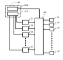
- FIG. 6 is a diagram illustrating an example of a configuration of a head control system in the liquid ejection head according to the present disclosure.
- the head control system in the liquid ejection head of the present disclosure includes a head control unit 101 and n drive circuits (first drive circuit D1, second drive circuit D2,..., Nth drive circuit Dn) (n is 2). The above natural number) and a switch circuit SW.
- n drive circuits first drive circuit D1, second drive circuit D2,..., Nth drive circuit Dn
- n is 2
- the above natural number and a switch circuit SW.
- a plurality of pressure units 30 are connected to the switch circuit SW.
- the head control unit 101 includes at least a first control circuit 101A and a second control circuit 101B.
- the head control unit 101 may be configured using an FPGA (field-programmable gate array), but may be configured using another PLD (programmable logic device) or an integrated circuit in some cases. It doesn't matter. By configuring the head control unit 101 using an FPGA, a liquid discharge head can be realized at low cost.
- FPGA field-programmable gate array
- PLD programmable logic device
- the pixel signal output from the above-described control unit 88 is input to the head control unit 101 for each drive cycle that is a cycle in which pixels are formed.
- This pixel signal is a digital signal indicating the operation of each of the plurality of ejection holes 8.
- each of the ejection holes 8 is a signal indicating which size pixel is to be ejected onto the recording medium.
- the first control circuit 101A controls a plurality of drive circuits (D1 to Dn) and outputs drive signals from the respective drive circuits.
- the drive signal is an analog signal that drives the pressurizing unit 30, and there are a plurality of types depending on how the pressurizing unit 30 is driven. For example, a corresponding drive signal is sent to the pressurizing unit 30 corresponding to each discharge hole 8 depending on which size of the pixel forming each pixel on the recording medium each discharge hole 8 discharges. .
- a drive signal that causes the pressurizing unit 30 to perform an operation of applying a pressure fluctuation to the liquid such that the liquid is not discharged from the discharge hole 8 may be included.
- the number of types of drive signals is appropriately set according to, for example, how finely the liquid discharge from each discharge hole 8 is controlled. For example, when finely controlling the liquid discharge, the number of drive signals is increased.
- the number of drive circuits (D1 to Dn) is set to a value equal to or greater than the number of types of drive signals. When a drive circuit that does not output a drive signal is provided, or when a drive circuit that changes the drive signal that is output according to the situation is provided, the number of drive circuits (D1 to Dn) increases. This will be described in detail later.
- the head control unit 101 When a pixel signal is input to the head control unit 101, the type of necessary drive signal and the number of pressure units that send each drive signal are obtained based on the pixel signal. Accordingly, it is determined which type of drive signal is output from which drive circuit. Then, the first control circuit 101A outputs a corresponding drive information signal to each drive circuit in accordance with the drive signal output by each drive circuit.
- This drive information signal is a signal for causing each drive circuit to output a drive signal, and there are the same number corresponding to the type of drive signal.
- the drive information signal is, for example, a digital signal having information on voltage change in the corresponding drive signal.
- the drive information signal may be included in the head control unit 101, or the drive information signal stored in another location may be read.
- Each drive circuit includes, for example, a DAC (digital-to-analog converter) and an amplifier circuit.
- the DAC converts the input drive information signal into an analog signal.
- the amplifier circuit has a multi-stage configuration as necessary, and amplifies and outputs the signal output from the DAC. In this way, each of the plurality of drive circuits (D1 to Dn) outputs a drive signal generated based on the input drive information signal to the switch circuit SW.
- This configuration is an example, and the configuration of each drive circuit is not limited to this.
- the switch circuit SW is connected to the drive circuit (D1 to Dn) and the plurality of pressure units 30, and switches the connection state between the drive circuit (D1 to Dn) and the plurality of pressure units 30. Specifically, the switch circuit SW connects each of the plurality of pressure units 30 to any one of the drive circuits (D1 to Dn).
- the switch circuit SW can be configured using, for example, a switch IC.
- a pixel signal When a pixel signal is input to the head control unit 101, it is determined which drive signal is input to each of the plurality of pressure units 30 based on the pixel signal. Then, based on which type of drive signal is output from which drive circuit, it is determined to which drive circuit each of the plurality of pressure units 30 is connected, and the connection signal having the information is the second control. The signal is output from the circuit 101B to the switch circuit SW. Then, the switch circuit SW connects each of the plurality of pressurizing units 30 to any one of the drive circuits (D1 to Dn) based on the input connection signal.
- the present invention is not limited to this.
- the head control unit 101 does not exist, the first control circuit 101A and the second control circuit 101B exist separately from each other, and pixel signals are respectively transmitted to the first control circuit 101A and the second control circuit 101B.
- An input configuration may be used.
- each of the first control circuit 101A and the second control circuit 101B may be divided and arranged in a plurality of portions.
- the first control circuit 101A and the second control circuit 101B may share at least part of each other. That is, the first control circuit 101A and the second control circuit 101B may be integrated.
- FIG. 7 is a diagram illustrating an example of rotation of the drive circuit in the liquid ejection head of the present disclosure.
- the configuration is simplified for ease of explanation, and there are three types of drive signals, ie, a first signal S1, a second signal S2, and a third signal S3, as drive signals.
- the circuit includes a first drive circuit D1, a second drive circuit D2, a third drive circuit D3, a fourth drive circuit D4, and a fifth drive circuit D5.
- the first signal S1 is a signal for discharging a droplet that forms a small-sized pixel on the recording medium
- the second signal S2 is a droplet that forms a medium-sized pixel on the recording medium.
- the third signal S3 is a signal for discharging a droplet that forms a large-sized pixel on a recording medium.
- the second signal S2 is, for example, a drive signal composed of a pulse having a pulse width of AL, and a signal for ejecting one droplet.
- the first signal S1 is, for example, a drive signal composed of a pulse having a pulse width of 0.7 AL, and is a signal for ejecting one droplet having a smaller volume than the droplet ejected by the second signal S2.
- the third signal S3 is, for example, a drive signal composed of two pulses having a pulse width of approximately AL, and is a signal for ejecting two droplets having substantially the same volume as the droplet ejected by the second signal S2.
- the two droplets are either a droplet that is discharged later, catches up with the previous droplet during flight, or becomes a single droplet, or spreads on the recording medium after landing separately on the recording medium.
- One pixel For example, the velocity of the two droplets can be made different by making the widths of the two pulses different. Further, by adjusting the interval between the two pulses, the fact that the residual vibration of the liquid remaining in the pressurizing chamber 10 after discharging the previous droplet affects the discharge speed of the next droplet, The speed of the two droplets can be different.
- the number of droplets is not limited to one, and one pixel may be formed by a plurality of droplets.
- non-output indicates a drive circuit that does not output a drive signal
- “reserve” indicates a drive circuit in which the output drive signal changes depending on the situation.
- t1, t2, t3, t4, t5, and t6 indicate times, respectively, indicating that time elapses from t1 to t6.
- the drive circuit that outputs the first signal S1 is the first drive circuit D1 at time t1, but with the passage of time, the second drive circuit D2 Then, the operation proceeds to the third drive circuit D3, the fourth drive circuit D4, and the fifth drive circuit D5, and becomes the first drive circuit D1 again at time t6.
- the process proceeds to the second drive circuit D2, the third drive circuit D3,... In the same order. That is, the drive circuit that outputs the first signal S1 is switched among the plurality of drive circuits (D1 to D5). That is, the drive circuit that outputs the first signal S1 is switched among the plurality of drive circuits (D1 to D5) with the passage of time.
- the first control circuit 101A changing the destination of the drive information signal corresponding to the first signal S1 over time. That is, the first control circuit 101A sets the destination of the drive information signal corresponding to the first signal S1 as the first drive circuit D1, the second drive circuit D2, the third drive circuit D3, and the third drive circuit with the passage of time from the time t1. This is realized by shifting to the four drive circuit D4, the fifth drive circuit D5, the first drive circuit D1,.
- the drive circuit that outputs the second signal S2 is the fifth drive circuit D5, the first drive circuit D1, the second drive circuit D2, and the third drive circuit D3 as time elapses from the time t1. Then, the process moves to the fourth drive circuit D4 and becomes the fifth drive circuit D5 again at time t6. After time t6, the first drive circuit D1, the second drive circuit D2, the third drive circuit D3,... Move in the same order.
- the drive circuit that outputs the third signal S3 has a fourth drive circuit D4, a fifth drive circuit D5, a first drive circuit D1, a second drive circuit D2, and a third drive as time elapses from time t1. It moves to the circuit D3,.
- the switch circuit SW connects each of the plurality of pressurizing units 30 to a drive circuit that outputs a drive signal to be input (a plurality of drive circuits that output a drive signal to be input exist). If so, connect to one of them).
- the liquid ejection head includes a plurality of ejection holes 8, a plurality of pressure units 30, a plurality of drive circuits (D1 to Dn), a switch circuit SW, a first control circuit 101A, A second control circuit 101B.
- the plurality of pressurizing units 30 pressurize the liquid and discharge the liquid from the discharge holes 8.
- the plurality of drive circuits (D1 to Dn) output drive signals for driving the plurality of pressure units 30.
- the switch circuit SW switches the connection between the plurality of pressure units 30 and the plurality of drive circuits (D1 to Dn).
- the first control circuit 101A controls a plurality of drive circuits (D1 to Dn).
- the second control circuit 101B controls the switch circuit SW.
- the liquid ejection head ejects, as drive signals, a first signal S1 for ejecting a droplet that forms a first size pixel and a droplet that forms a second size pixel different from the first size. And a plurality of types of signals including at least a second signal S2 to be performed.
- the first control circuit 101A controls the plurality of drive circuits (D1 to Dn) so that different types of drive signals are output from different drive circuits.
- Each of the plurality of pressure units 30 is connected to a drive circuit that outputs a first signal S1 when ejecting a droplet that forms a first size pixel, and drops that form a second size pixel.
- the second control circuit 101B controls the switch circuit SW so as to be connected to the drive circuit outputting the second signal S2. That is, the pressurizing unit 30 that ejects droplets that form pixels of the first size is connected to the drive circuit that outputs the first signal S1, and the pressurizer that ejects droplets that form the pixels of the second size.
- the second control circuit 101B controls the switch circuit SW so that 30 is connected to the drive circuit that outputs the second signal S2.
- the first control circuit 101A controls the plurality of drive circuits (D1 to Dn) so that the drive circuit in charge of outputting the first signal S1 is switched among the plurality of drive circuits (D1 to Dn). This is the basic configuration of the liquid ejection head of the present disclosure.
- the temperature of a specific drive circuit excessively rises even when the number of pressure units 30 to which the first signal S1 is input continues. Can be reduced. As a result, the occurrence of malfunction of the drive circuit due to temperature rise can be reduced.
- the liquid ejection head of the present disclosure only needs to have this basic configuration, and other configurations are not essential and can be changed as appropriate.
- the drive circuit in charge of the output of each of the plurality of types of drive signals (S1 to S3) rotates in the plurality of drive circuits (D1 to Dn) as time passes.
- the first control circuit 101A can control a plurality of drive circuits (D1 to Dn). In the case of such a configuration, the temperature of the specific drive circuit is excessive even when the state where the number of the pressurizing units 30 to which any of the plurality of types of drive signals (S1 to S3) is input continues to be large. Can be reduced.
- the first control circuit 101A may control the plurality of drive circuits so as to move among the plurality of drive circuits.
- the drive circuit that does not output the drive signal moves from the time t1 to the third drive circuit D3, the fourth drive circuit D4, the fifth drive circuit D5,. Go. That is, in the driving circuit of this example, a part of the plurality of driving circuits (D1 to Dn) does not output a driving signal, and the driving circuit that does not output a driving signal has a plurality of driving circuits (D1 to Dn over time). ),
- the first control circuit 101A can control the plurality of drive circuits (D1 to Dn). In the case of such a configuration, since the heat generation of the drive circuit is suppressed while the drive signal is not output, a significant temperature increase of the specific drive circuit can be reduced.
- the liquid ejection head according to the present disclosure can have a configuration in which the number of drive circuits is greater than the number of types of drive signals. In the case of such a configuration, it becomes possible to provide a drive circuit that does not output a drive signal, or to output one drive signal from a plurality of drive circuits, so that an excessive temperature rise in a specific drive circuit Can be more effectively reduced. In some cases, the number of drive circuits may be the same as the number of drive circuits.
- FIG. 8 is a plan view schematically showing an example of the arrangement of the drive circuit on the liquid discharge head according to the present disclosure. Specifically, the liquid discharge head when the drive circuit is rotated as shown in FIG. An example of the arrangement of the upper drive circuit is shown.
- each of the drive circuits (D1 to Dn) is mounted on the head control substrate together with the head control unit 101, and the head control substrate is mounted on the liquid ejection head.
- the switch circuit SW is disposed on, for example, an FPC (flexible printed circuit) that functions as the signal transmission unit 60 described above, and the head control unit 101, the drive circuits (D1 to Dn), and the plurality of pressurizing units via the FPC.
- FPC flexible printed circuit
- it may be mounted on the head control board together with the head control unit 101 and the drive circuits (D1 to Dn).
- the drive circuits (D1 to D5) are arranged side by side along the + Y direction. Specifically, the first drive circuit D1, the fourth drive circuit D4, the second drive circuit D2, the fifth drive circuit D5, and the third drive circuit D3 are arranged at equal intervals in the + Y direction. In this arrangement, the drive circuit pairs closest to each other are the first drive circuit D1 and the fourth drive circuit D4, the fourth drive circuit D4 and the second drive circuit D2, the second drive circuit D2 and the fifth drive circuit D5, Four pairs of five drive circuits D5 and third drive circuits D3.
- the drive circuits are arranged in the order of. Therefore, pairs of drive circuits adjacent to each other in this arrangement are the first drive circuit D1 and the second drive circuit D2, the second drive circuit D2 and the third drive circuit D3, the third drive circuit D3 and the fourth drive circuit D4, There are five pairs of the fourth drive circuit D4 and the fifth drive circuit D5, and the fifth drive circuit D5 and the first drive circuit D1.
- the five pairs adjacent to each other in the rotation arrangement of the drive circuits shown in FIG. 7 and the four pairs closest to each other in the arrangement of the drive circuits on the liquid ejection head shown in FIG. Not done (no duplicates). That is, the drive circuits adjacent to each other in the rotation arrangement are different from the drive circuits closest to each other in the arrangement on the liquid ejection head.
- FIG. 9 is a plan view schematically showing another example of the arrangement of the drive circuits on the liquid ejection head according to the present disclosure. Specifically, it has six drive circuits, a first drive circuit D1 to a sixth drive circuit D6, and in rotation, the first drive circuit D1, the second drive circuit D2, the third drive circuit D3, and the fourth drive circuit D4. , An example of the arrangement of the drive circuits on the liquid ejection head when the drive circuits are arranged in the order of the fifth drive circuit D5, the sixth drive circuit D6, the first drive circuit D1,. .
- the six drive circuits (D1 to D6) are arranged along the + X direction and the + Y direction orthogonal to each other, arranged in two rows in the + X direction and in three rows in the + Y direction.
- the third drive circuit D3, the fifth drive circuit D5, and the first drive circuit D1 are sequentially arranged in the + Y direction
- the second row in the + X direction is The sixth drive circuit D6, the second drive circuit D2, and the fourth drive circuit D4 are arranged in this order in the + Y direction.
- the interval between the drive circuits adjacent in the + X direction and the interval between the drive circuits adjacent in the + Y direction are all equal.
- the drive circuits closest to each other in this arrangement are the first drive circuit D1 and the fourth drive circuit D4, the fourth drive circuit D4 and the second drive circuit D2, the second drive circuit D2 and the fifth drive circuit D5, and the fifth drive. Seven pairs of a circuit D5 and a third drive circuit D3, a third drive circuit D3 and a sixth drive circuit D6, a sixth drive circuit D6 and a second drive circuit D2, and a first drive circuit D1 and a fifth drive circuit D5. .
- the drive circuits adjacent to each other in the drive circuit arrangement in the rotation of the drive circuit are the first drive circuit D1, the second drive circuit D2, the second drive circuit D2, the third drive circuit D3, and the third drive circuit.
- the liquid discharge head according to the present disclosure may have a configuration in which drive circuits adjacent to each other in the rotation arrangement are different from drive circuits closest to each other in the arrangement on the liquid discharge head. In the case of such a configuration, an excessive temperature rise in a specific drive circuit can be reduced.
- the two drive circuits are the most in the arrangement on the liquid ejection head. It becomes a drive circuit that is close.
- FIG. 10 is a diagram illustrating an example of a drive signal output at each time in each drive circuit when rotation of the drive circuit illustrated in FIG. 7 is performed.
- “non-output” indicates that the drive signal is not output.
- “Reserve” in FIG. 7 means a drive circuit in which an output drive signal changes depending on the situation, as described above.
- the “reserve” operation is performed, for example, when the number of the pressure units 30 connected to the drive circuit that outputs one drive signal exceeds a predetermined reference value, and the drive signal is output otherwise. Can be set not to output a drive signal.
- at time t2 and time t3 only the number of pressure units 30 connected to the drive circuit that outputs the first signal S1 exceeds a predetermined reference value, and at time t5 and time t6, The case where only the number of the pressurization parts 30 connected to the drive circuit which outputs 2nd signal S2 exceeds a predetermined reference value is shown.
- the drive circuit that is “reserved” has the second drive circuit D2, the third drive circuit D3, the fourth drive circuit D4, the fifth drive circuit D5, the first drive circuit as time elapses from time t1.
- FIG. 10 shows that “reserve” outputs the first signal S1 at time t2 and time t3, outputs the second signal S2 at time t5 and time t6, and drives at time t1 and time t4. No signal is output.
- the second drive circuit D2 and the third drive circuit D3 output the first signal S1, and at time t3, the third drive circuit D3.
- the fourth drive circuit D4 outputs the first signal S1, the first drive circuit D1 and the fourth drive circuit D4 output the second signal S2 at time t5, and the second drive circuit D2 and the fifth drive signal at time t6.
- the drive circuit D5 outputs the second signal S2.
- the first control circuit 101A controls the plurality of drive circuits (D1 to Dn) so that at least two drive circuits output the same type of drive signal at a certain time.
- the number of pressure units 30 connected to the drive circuit that outputs the first signal S1 is connected to the drive circuit that outputs the second signal S2.
- the number of the pressurization parts 30 are more than the number of the pressurization parts 30, and the number of the drive circuits which output 1st signal S1 is larger than the number of the drive circuits which output 2nd signal S2. That is, in the liquid ejection head of this example, at a certain point in time, the number of the pressure units 30 connected to the drive circuit that outputs the first signal S1 is equal to the drive circuit that outputs the second signal S2.
- control circuit 101A controls a plurality of drive circuits).
- the number of drive circuits that output drive signals with a large number of output destination pressurizing units 30 can be increased, so that an excessive temperature rise in a specific drive circuit and an increase in temperature difference between the drive circuits can be prevented. Can be reduced.
- the number of pressure units connected to each drive circuit is counted while assigning each drive signal and the pressure unit 30 to the corresponding drive circuit based on the input pixel signal. And when the number of the pressurization parts 30 connected to the drive circuit which outputs a certain drive signal (for example, set it as 1st signal S1) exceeds the predetermined reference value, "reserve" of 1st signal S1 is carried out. After assigning the output, the pressurizing unit 30 for sending the first signal S1 is connected to “reserve” after that. In this way, control using “reserve” can be performed.
- each drive signal may be assigned to a plurality of drive circuits in advance. Further, instead of counting the number of pressure units 30 connected to each drive circuit, the number of output of each drive signal (the number of pressure units 30 to which the drive signal is sent) may be counted. In this case, for example, when a plurality of reference values are provided and the number of outputs of the drive signal exceeds the first reference value, the output of the drive signal is assigned to the first “reserve” thereafter, and the drive is performed. When the number of signal outputs exceeds the second reference value, control can be performed so as to assign the output of the drive signal to the second “reserve” thereafter.
- the history of the number of connections of each drive circuit (the number of pressure units connected to the drive circuit)
- the number of connections of each drive circuit and the number of outputs of each drive signal in the past one to a plurality of discharges are counted, and the output of the drive signal with the smaller number of outputs is assigned to the drive circuit with the larger number of connections.
- the heat generation amount (or power consumption) of each drive circuit in the past ejection is obtained, and the drive circuit to be output is exchanged between the drive circuit having the largest number and the drive circuit having the least amount, and the drive circuit having the second largest number It is also possible to exchange the drive signals to be output by the second least drive circuit, and to shift the drive circuit.
- a sensor for detecting the temperature of each drive circuit may be installed, and the drive circuit may be rotated based on information from the sensor.
- the output of the drive signal (for example, the first signal S1) with a small number of outputs is canceled.
- the first signal S1 is supposed to be sent to the pressurizing unit 30 instead of the first signal S1
- the second signal S2 is sent from another driving circuit, and the output of the first signal S1 is supposed to be assigned. It is also possible to assign the output of another drive signal having a large number of outputs to the circuit.
- FIG. 7 shows an example in which the drive circuits (D1 to Dn) are connected to one switch circuit SW.
- the number of ejection holes 8 is large, a plurality of switch circuits SW are provided to provide a plurality of switch circuits SW.
- Each of the switch circuits SW may be connected to all of the drive circuits (D1 to Dn). For example, if the number of ejection holes 8 is 2,400, the number of output terminals of one switch circuit SW is 400, and the number of drive circuits is 16, then 16 in one head controller 101.
- the pressurizing unit 30 may be connected. If two such configurations are provided, 4800 pressure units 30 can be controlled together. That is, the pressure units 30 included in the liquid ejection head are divided into a plurality of groups, and a plurality of head drive systems as shown in FIG. 7 are provided to control the pressure units 30 belonging to each group.
- the drive system may be in charge.
- another liquid ejection head of the present disclosure includes, for example, a plurality of pressure units 30, a plurality of drive circuits (D1 to Dn), a switch circuit SW, a first control circuit 101A, and a second control circuit 101B. And have.
- the plurality of pressurizing units 30 pressurize the liquid and discharge the liquid from the discharge holes 8.
- the plurality of drive circuits (D1 to Dn) output drive signals for driving the plurality of pressure units 30.
- the switch circuit SW switches the connection between the plurality of pressure units 30 and the plurality of drive circuits (D1 to Dn).
- the first control circuit 101A controls a plurality of drive circuits (D1 to Dn).
- the second control circuit 101B controls the switch circuit SW.
- the liquid ejection head ejects, as drive signals, a first signal S1 for ejecting a droplet that forms a first size pixel and a droplet that forms a second size pixel different from the first size. And a plurality of types of signals including at least a second signal S2 to be performed.
- the first control circuit 101A controls the plurality of drive circuits (D1 to Dn) so that different types of drive signals are output from different drive circuits.
- Each of the plurality of pressure units 30 is connected to a drive circuit that outputs a first signal S1 when ejecting a droplet that forms a first size pixel, and drops that form a second size pixel.
- the second control circuit 101B controls the switch circuit SW so as to be connected to the drive circuit outputting the second signal S2. That is, the pressurizing unit 30 that ejects droplets that form pixels of the first size is connected to the drive circuit that outputs the first signal S1, and the pressurizer that ejects droplets that form the pixels of the second size.
- the second control circuit 101B controls the switch circuit SW so that 30 is connected to the drive circuit that outputs the second signal S2.
- the first control circuit 101A and the second control circuit 101B are mounted on the FPGA.
- the first control circuit 101A has a plurality of drive circuits in charge of outputting the first signal S1 over time. It is difficult to control a plurality of drive circuits (D1 to Dn) so as to move in the drive circuits (D1 to Dn) by control by a program.
- the first control circuit 101A and the second control circuit 101B are mounted on the FPGA, it is possible to realize a liquid discharge head capable of such an operation at a low cost.
- liquid ejection head according to the present disclosure is not limited to the specific example described above, and various modifications can be made. The configuration described in different examples may be combined.
- ..Piezoelectric actuator substrate 21a Piezoelectric ceramic layer (vibrating plate) 21b ... Piezoelectric ceramic layer 24 ... Common electrode 25 ... Individual electrode 25a ... Individual electrode body 25b ... Extraction electrode 26 ... Connection electrode 28 ... Surface electrode for common electrode 30 ... Pressure unit 60: Signal transmission unit 70: Head mounting frame 72 ... Head group 80A ... Paper feed roller 80B ... Collection roller 82A ... Guide roller 82B ... Conveyance roller 88 ... Control part P ... Printing paper 101 ... Head control part 101A ... First control circuit 101B ... Second control circuit D1-Dn ... Drive circuit D1 ... First drive circuit D2 ... Second drive circuit D3 ... Third drive circuit D4 ... Fourth drive circuit D5 ... Fifth drive circuit D6 ... Sixth drive circuit S1 ... First signal S2 ... ⁇ Second signal S3 ... Third No. SW ⁇ switch circuit
Abstract
本開示の液体吐出ヘッドは、複数の吐出孔8、複数の加圧部30、複数の駆動回路(D1~Dn)、スイッチ回路SW、第1制御回路101A、第2制御回路101Bを有し、駆動信号として、第1サイズの画素用の第1信号S1と第2サイズの画素用の第2信号S2を含む複数種類を有する。第1制御回路101Aは、異なる種類の駆動信号が異なる駆動回路から出力されるように駆動回路を制御する。複数の加圧部30の各々が、第1サイズの画素を形成する液滴を吐出するときには第1信号S1を出力している駆動回路に接続され、第2サイズの画素を形成する液滴を吐出するときには第2信号S2を出力している駆動回路に接続されるように、第2制御回路101Bがスイッチ回路SWを制御する。第1制御回路101Aは、第1信号S1の出力を担当する駆動回路が複数の駆動回路の中で入れ替わるように駆動回路を制御する。
Description
本開示は、液体吐出ヘッドおよびそれを用いた記録装置に関する。
従来、液体吐出ヘッドとして、液体を記録媒体上に吐出することによって各種の印刷を行うインクジェットヘッドが知られている。このような液体吐出ヘッドでは、複数の加圧部によって液体を加圧することにより、各々の加圧部に対応して設けられた複数の吐出孔から液体が吐出される。(例えば、特許文献1を参照。)。
本開示の液体吐出ヘッドは、複数の吐出孔と、複数の加圧部と、複数の駆動回路と、スイッチ回路と、第1制御回路と、第2制御回路と、を有している。前記複数の加圧部は、液体を加圧して前記吐出孔から吐出する。前記駆動回路は、前記複数の加圧部を駆動する駆動信号を出力する。前記スイッチ回路は、前記複数の加圧部と前記複数の駆動回路との接続を切り替える。前記第1制御回路は、前記複数の駆動回路を制御する。前記第2制御回路は、前記スイッチ回路を制御する。前記液体吐出ヘッドは、前記駆動信号として、第1サイズの画素を形成する液滴を吐出するための第1信号と、前記第1サイズと異なる第2サイズの画素を形成する液滴を吐出するための第2信号と、を少なくとも含む複数種類の信号を有する。前記第1制御回路は、異なる種類の前記駆動信号が異なる前記駆動回路から出力されるように、前記複数の駆動回路を制御する。前記複数の加圧部の各々が、前記第1サイズの画素を形成する液滴を吐出するときには前記第1信号を出力している前記駆動回路に接続され、前記第2サイズの画素を形成する液滴を吐出するときには前記第2信号を出力している前記駆動回路に接続されるように、前記第2制御回路が前記スイッチ回路を制御する。前記第1制御回路は、前記第1信号の出力を担当する前記駆動回路が前記複数の駆動回路の中で入れ替わるように、前記複数の駆動回路を制御する。
本開示の記録装置は、前記液体吐出ヘッドと、記録媒体を前記液体吐出ヘッドに対して搬送する搬送部と、を備えている。
特許文献1に記載されたようなインクジェットヘッドでは、加圧部を駆動するための駆動信号を生成し、その駆動信号をそれぞれの加圧部に送ることによって各加圧部を駆動する。しかしながら、同時に多数の吐出孔から液体を吐出するインクジェットヘッドでは、同時に多数の加圧部に駆動信号を送る必要があるため、駆動信号を生成する回路(特にその中に存在する電力増幅器)の大型化や発熱が問題となる。
このような問題を解決するために、記録媒体上に形成する画素のサイズ(例えば、小画素、中画素、大画素)等に応じた複数種類の駆動信号を、それぞれ異なる回路で生成することが考えられる。しかしながら、複数種類の駆動信号を異なる回路で生成するようにした場合には、それぞれの駆動信号が送られる加圧部の数の大小により、それぞれの駆動信号を生成する回路の発熱量に差が生じる(例えば、ベタのパターンを印刷するような場合には、大画素に対応する駆動信号が送られる加圧部の数が著しく増加し、大画素に対応する駆動信号を生成する回路の発熱量が著しく増加する。)。よって、それぞれの駆動信号を生成する回路の発熱量に差がある状態が一定時間続くと、特定の回路の温度が過度に上昇して動作不良になるという問題や、液体吐出ヘッドの場所による温度の差異が大きくなることにより液体の吐出精度が悪化するという問題が生じる。
本開示の液体吐出ヘッドは、特定の回路の過度の温度上昇を低減することができ、複数の回路間の温度差を低減することができる。これにより、温度上昇による回路の動作不良の発生を低減することができる。また、液体吐出ヘッド上における駆動回路の配置によっては、液体吐出ヘッドの場所による温度の差異の増大による吐出精度の悪化を低減することができる。以下、本開示の液体吐出ヘッドおよびそれを用いた記録装置について詳細に説明する。
図1Aおよび図1Bは、本開示の液体吐出ヘッドを含む記録装置の一例であるカラーインクジェットプリンタ1(以下で単にプリンタと言うことがある)の概略の図面である。なお、図1Aは側面図であり、図1Bは平面図である。プリンタ1は、記録媒体である印刷用紙Pをガイドローラ82Aから搬送ローラ82Bへと搬送することにより、印刷用紙Pを液体吐出ヘッド2に対して相対的に移動させる。そして、プリンタ1は、制御部88によって液体吐出ヘッド2を制御して、画像や文字のデータに基づいて液体吐出ヘッド2から液体を吐出し、印刷用紙Pに液滴を着弾させる。このようにして、プリンタ1は、印刷用紙Pに印刷などの記録を行う。
本例では、液体吐出ヘッド2はプリンタ1に対して固定されており、プリンタ1はいわゆるラインプリンタとなっているが、これに限定されるものではない。例えば、液体吐出ヘッド2を、印刷用紙Pの搬送方向に交差する方向、例えば、ほぼ直交する方向に往復させるなどして移動させる動作と、印刷用紙Pの搬送を交互に行う、いわゆるシリアルプリンタでも良い。
プリンタ1には、印刷用紙Pとほぼ平行になるように平板状のヘッド搭載フレーム70(以下で単にフレームと言うことがある)が固定されている。フレーム70には図示しない20個の孔が設けられており、20個の液体吐出ヘッド2がそれぞれの孔の部分に搭載されていて、液体吐出ヘッド2の、液体を吐出する部位が印刷用紙Pに面するようになっている。液体吐出ヘッド2と印刷用紙Pとの間の距離は、例えば0.5~20mm程度とされる。なお、図1では、20個の液体吐出ヘッド2のうち5つの液体吐出ヘッド2によって1つのヘッド群72が構成され、プリンタ1が4つのヘッド群72を有している例を示している。
液体吐出ヘッド2は、図1Aの手前から奥へ向かう方向、図1Bの上下方向に細長い長尺形状を有している。この長い方向を長手方向と呼ぶことがある。1つのヘッド群72内において、3つの液体吐出ヘッド2は、印刷用紙Pの搬送方向に交差する方向、例えば、ほぼ直交する方向に沿って並んでいる。他の2つの液体吐出ヘッド2は、搬送方向に沿ってずれた位置で、3つの液体吐出ヘッド2の間にそれぞれ一つずつ並んでいる。液体吐出ヘッド2は、各液体吐出ヘッド2で印刷可能な範囲が、印刷用紙Pの幅方向に(印刷用紙Pの搬送方向に交差する方向に)繋がるように、あるいは端が重複するように配置されており、印刷用紙Pの幅方向に隙間のない印刷が可能になっている。
4つのヘッド群72は、印刷用紙Pの搬送方向に沿って配置されている。各液体吐出ヘッド2には、図示しない液体タンクから液体、例えば、インクが供給される。1つのヘッド群72に属する液体吐出ヘッド2には、同じ色のインクが供給されるようになっており、4つのヘッド群72で4色のインクが印刷できる。各ヘッド群72から吐出されるインクの色は、例えば、マゼンタ(M)、イエロー(Y)、シアン(C)およびブラック(K)である。このようなインクを、制御部88で制御して印刷すれば、カラー画像が印刷できる。
プリンタ1に搭載されている液体吐出ヘッド2の個数は、単色印刷であり、且つ1つの液体吐出ヘッド2で印刷可能な範囲を印刷する場合であれば、1つでもよい。ヘッド群72に含まれる液体吐出ヘッド2の個数や、ヘッド群72の個数は、印刷する対象や印刷条件により適宜変更できる。例えば、さらに多色の印刷をするためにヘッド群72の個数を増やしてもよい。また、同色で印刷するヘッド群72を複数配置して、搬送方向に交互に印刷すれば、同じ性能の液体吐出ヘッド2を使用しても搬送速度を速くできる。これにより、時間当たりの印刷面積を大きくすることができる。また、同色で印刷するヘッド群72を複数準備して、搬送方向と交差する方向にずらして配置して、印刷用紙Pの幅方向の解像度を高くしてもよい。
さらに、色の付いたインクを印刷する以外に、印刷用紙Pの表面処理をするために、コーティング剤などの液体を印刷してもよい。
プリンタ1は、記録媒体である印刷用紙Pに印刷を行う。印刷用紙Pは、給紙ローラ80Aに巻き付けられた状態になっており、2つのガイドローラ82Aの間を通った後、フレーム70に搭載されている液体吐出ヘッド2の下側を通り、その後2つの搬送ローラ82Bの間を通り、最終的に回収ローラ80Bに回収される。印刷する際には、搬送ローラ82Bを回転させることにより、印刷用紙Pが一定速度で搬送され、液体吐出ヘッド2によって印刷される。回収ローラ80Bは、搬送ローラ82Bから送り出された印刷用紙Pを巻き取る。このように、給紙ローラ80A、ガイドローラ82A、搬送ローラ82B、回収ローラ80Bによって、印刷用紙Pを液体吐出ヘッド2に対して搬送する搬送部が構成されている。搬送速度は、例えば、75m/分とされる。各ローラは、制御部88によって制御されてもよいし、人によって手動で操作されてもよい。
記録媒体は、印刷用紙P以外に、ロール状の布などでもよい。また、プリンタ1は、印刷用紙Pを直接搬送する代わりに、搬送ベルトを直接搬送して、記録媒体を搬送ベルト上に置いて搬送してもよい。そのようにすれば、枚葉紙や裁断された布、木材、タイルなどを記録媒体にできる。さらに、液体吐出ヘッド2から導電性の粒子を含む液体を吐出するようにして、電子機器の配線パターンなどを印刷してもよい。またさらに、液体吐出ヘッド2から反応容器などに向けて所定量の液体の化学薬剤や化学薬剤を含んだ液体を吐出させて、反応させるなどして、化学薬品を作製してもよい。
また、プリンタ1に、位置センサ、速度センサ、温度センサなどを取り付けて、制御部88が、各センサからの情報から分かるプリンタ1各部の状態に応じて、プリンタ1の各部を制御してもよい。例えば、液体吐出ヘッド2の温度や液体タンクの液体の温度、液体タンクの液体が液体吐出ヘッド2に加えている圧力などが、吐出される液体の吐出量や吐出速度などの吐出特性に影響を与えている場合などに、それらの情報に応じて、液体を吐出させる駆動信号を変えるようにしてもよい。
なお、本開示における記録装置は、液体吐出ヘッドと、記録媒体を前記液体吐出ヘッドに対して搬送する搬送部とを備えていれば良く、その他の構成については何ら限定されるものではない。また、前記搬送部の構成についても、本実施形態で示した構成に限定されるものではない。
次に、本開示の液体吐出ヘッドの構成の一例について説明する。図2は、図1に示された液体吐出ヘッド2の要部であるヘッド本体2aを示す平面図である。図3は、図2の一点鎖線で囲まれた領域の拡大平面図であり、ヘッド本体2aの一部である。図3では、説明のため、一部の流路を省略して描いている。図4は、図3と同じ位置の拡大平面図であり、図3とは別の一部の流路を省略して描いている。図5は、図3のV-V線に沿った縦断面図である。なお、図3および図4において、図面を分かり易くするために、圧電アクチュエータ基板21の下方にあって破線で描くべき加圧室10、しぼり6および吐出孔8などを実線で描いている。
液体吐出ヘッド2は、ヘッド本体2a以外に、ヘッド本体2aに液体を供給するリザーバや、筐体を含んでいてもよい。また、ヘッド本体2aは、流路部材4と、加圧部30が作り込まれている圧電アクチュエータ基板21とを含んでいる。
ヘッド本体2aを構成する流路部材4は、共通流路であるマニホールド5と、マニホールド5と繋がっている複数の加圧室10と、複数の加圧室10とそれぞれ繋がっている複数の吐出孔8とを備えている。加圧室10は流路部材4の上面に開口しており、流路部材4の上面が加圧室面4-2となっている。また、流路部材4の上面は、マニホールド5と繋がっている開口5aを有し、この開口5aより液体が供給されるようになっている。
また、流路部材4の上面には、加圧部30を含む圧電アクチュエータ基板21が接合されており、各加圧部30が加圧室10上に位置するように配置されている。また、圧電アクチュエータ基板21には、各加圧部30に信号を供給する信号伝達部60が接続されている。図2には、2つの信号伝達部60が圧電アクチュエータ基板21に繋がる状態が分かるように、信号伝達部60の圧電アクチュエータ基板21に接続される付近の外形を点線で示した。圧電アクチュエータ基板21に電気的に接続されている、信号伝達部60に形成されている電極は、信号伝達部60の端部に、矩形状に配置されている。2つの信号伝達部60は、圧電アクチュエータ基板21の短手方向の中央部にそれぞれの端がくるように接続されている。
ヘッド本体2aは、平板状の流路部材4と、流路部材4上に接合された加圧部30を含む圧電アクチュエータ基板21を1つ有している。圧電アクチュエータ基板21の平面形状は長方形状であり、その長方形の長辺が流路部材4の長手方向に沿うように流路部材4の上面に配置されている。
流路部材4の内部には2つのマニホールド5が形成されている。マニホールド5は流路部材4の長手方向の一端部側から、他端部側に延びる細長い形状を有しており、その両端部において、流路部材4の上面に開口しているマニホールド5の開口5aが形成されている。
また、マニホールド5は、少なくとも加圧室10に繋がっている領域である長手方向における中央部分において、短手方向に間隔を開けて設けられた隔壁15で仕切られている。隔壁15は、加圧室10に繋がっている領域である長手方向の中央部分においては、マニホールド5と同じ高さを有し、マニホールド5を複数の部分に完全に仕切っている。このようにすることで、平面視したときに、隔壁15と重なるように、吐出孔8および吐出孔8から加圧室10に繋がっている流路を設けることができる。
複数に分けられた部分のマニホールド5を副マニホールド5bと呼ぶことがある。本実施形態においては、マニホールド5は独立して2本設けられており、それぞれの両端部に開口5aが設けられている。また、1つのマニホールド5には、7つの隔壁15が設けられており、8つの副マニホールド5bに分けられている。副マニホールド5bの幅は、隔壁15の幅より大きくなっており、これにより副マニホールド5bに多くの液体を流すことができる。
流路部材4は、複数の加圧室10が2次元的に広がって形成されている。加圧室10は、角部にアールが施されたほぼ菱形あるいは楕円形状の平面形状を有する中空の領域である。
加圧室10は、しぼり6を介して1つの副マニホールド5bと繋がっている。1つの副マニホールド5bに沿うようにして、この副マニホールド5bに繋がっている加圧室10の行である加圧室行11が、副マニホールド5bの両側に1行ずつ、合計2行設けられている。したがって、1つのマニホールド5に対して、16行の加圧室11が設けられており、ヘッド本体2a全体では32行の加圧室行11が設けられている。各加圧室行11における加圧室10の長手方向の間隔は同じであり、例えば、37.5dpiの間隔となっている。
各加圧室行11の端にはダミー加圧室16の列が1列設けられている。このダミー加圧室列のダミー加圧室16は、マニホールド5とは繋がっているが、吐出孔8とは繋がっていない。また、32行の加圧室行11の外側には、ダミー加圧室16が直線状に並んだダミー加圧室行が1行設けられている。このダミー加圧室行のダミー加圧室16は、マニホールド5および吐出孔8のいずれとも繋がっていない。これらのダミー加圧室16により、端から1つ内側の加圧室10の周囲の構造(剛性)が他の加圧室10の構造(剛性)と近くなることで、液体吐出特性の差を少なくできる。なお、周囲の構造の差の影響は、距離の近い、長さ方向に隣接する加圧室10の影響が大きいため、長さ方向には、両端にダミー加圧室を設けてある。幅方向については、影響が比較的小さいため、ヘッド本体21aの端に近い方のみに設けている。これにより、ヘッド本体21aの幅を小さくできる。
1つのマニホールド5に繋がっている加圧室10は、矩形状の圧電アクチュエータ基板21の各外辺に沿った行および列を成す格子状に配置されている。これにより、圧電アクチュエータ基板21の外辺から、加圧室10の上に形成されている個別電極25が等距離に配置されることになるので、個別電極25を形成する際に、圧電アクチュエータ基板21に変形が生じ難くできる。圧電アクチュエータ基板21と流路部材4とを接合する際に、この変形が大きいと外辺に近い加圧部30に応力が加わり、変位特性にばらつきが生じるおそれがあるが、変形を少なくすることで、そのばらつきを低減できる。また、もっとも外辺に近い加圧室行11の外側にダミー加圧室16のダミー加圧室行が設けられているために、変形の影響をより受け難くできる。加圧室行11に属する加圧室10は等間隔で配置されており、加圧室行11に対応する個別電極25も等間隔で配置されている。加圧室行11は短手方向に等間隔で配置されており、加圧室行11に対応する個別電極25の行も短手方向に等間隔で配置されている。これにより、特にクロストークの影響が大きくなる部位をなくすことができる。
本実施形態では、加圧室10は格子状に配置したが、隣り合う加圧室列11の加圧室10が互いの間に位置するように千鳥状に配置してもよい。このようにすると、隣接加圧室行11に属する加圧室10の間の距離がより長くなるので、よりクロストークを抑制できる。
加圧室行11をどのように並べるかによらず、流路部材4を平面視したとき、1つの加圧室行11に属する加圧室10が、隣接する加圧室行11に属する加圧室10と、液体吐出ヘッド2の長手方向において、重ならないように配置することにより、クロストークを抑制できる。一方、加圧室行11の間の距離を離すと、液体吐出ヘッド2の幅が大きくなるので、プリンタ1に対する液体吐出ヘッド2の設置角度の精度や、複数の液体吐出ヘッド2を使用する際の、液体吐出ヘッド2の相対位置の精度が印刷結果に与える影響が大きくなる。そこで、隔壁15の幅を副マニホールド5bよりも小さくすることで、それらの精度が印刷結果に与える影響を少なくできる。
1つの副マニホールド5bに繋がっている加圧室10は、2列の加圧室行11を成しており、1つの加圧室行11に属する加圧室10から繋がっている吐出孔8は、1つの吐出孔行9を成している。2行の加圧室行11に属する加圧室10に繋がっている吐出孔8はそれぞれ、副マニホールド5bの異なる側に開口している。図4では隔壁15には、2行の吐出孔行9が設けられているが、それぞれの吐出孔行9に属する吐出孔8は、吐出孔8に近い側の副マニホールド5bに加圧室10を介して繋がっている。隣接する副マニホールド5bに加圧室行11を介して繋がっている吐出孔8と液体吐出ヘッド2の長手方向において重ならないように配置されていると、加圧室10と吐出孔8とを繋ぐ流路間のクロストークが抑制できるので、さらにクロストークを少なくすることができる。加圧室10と吐出孔8とを繋ぐ流路全体が、液体吐出ヘッド2の長手方向において重ならないように配置されていると、さらにクロストークを少なくすることができる。
1つのマニホールド5に繋がっている複数の加圧室10により加圧室群が構成されており、マニホールド5が2つあるため、加圧室群は2つある。各加圧室群内における吐出に関わる加圧室10の配置は同じで、短手方向に平行移動させた位置に配置されている。これらの加圧室10は、流路部材4の上面における圧電アクチュエータ基板21に対向する領域に、加圧室群間などの少し間隔が広くなった部分があるものの、ほぼ全面にわたって配列されている。つまり、これらの加圧室10によって形成された加圧室群は圧電アクチュエータ基板21とほぼ同一の形状の領域を占有している。また、各加圧室10の開口は、流路部材4の上面に圧電アクチュエータ基板21が接合されることで閉塞されている。
加圧室10のしぼり6が繋がっている角部と対向する角部からは、流路部材4の下面の吐出孔面4-1に開口している吐出孔8に繋がる流路が伸びている。この流路は、平面視において、加圧室10から離れる方向に伸びている。より具体的には、加圧室10の長い対角線に沿う方向に離れつつ、その方向に対して左右にずれながら伸びている。これにより、加圧室10は各加圧室行11内での間隔が37.5dpiになっている格子状の配置にしつつ、吐出孔8は、全体で1200dpiの間隔で配置することができる。
これは別の言い方をすると、流路部材4の長手方向に平行な仮想直線に対して直交するように吐出孔8を投影すると、図4に示した仮想直線のRの範囲に、各マニホールド5に繋がっている16個の吐出孔8、全部で32個の吐出孔8が、1200dpiの等間隔となっているということである。これにより、すべてのマニホールド5に同じ色のインクを供給することで、全体として長手方向に1200dpiの解像度で画像が形成可能となる。また、1つのマニホールド5に繋がっている1個の吐出孔8は、仮想直線のRの範囲で600dpiの等間隔になっている。これにより、各マニホールド5に異なる色のインクを供給することで、全体として長手方向に600dpiの解像度で2色の画像が形成可能となる。この場合、2つの液体吐出ヘッド2を用いれば、600dpiの解像度で4色の画像が形成可能となり、600dpiで印刷可能な液体吐出ヘッドを4つ用いるよりも、印刷精度が高くなり、印刷のセッティングも簡単にできる。なお、ヘッド本体2aの短手方向に並んでいる1列の加圧室列に属する加圧室10から繋がっている吐出孔8で、仮想直線のRの範囲がカバーされている。
圧電アクチュエータ基板21の上面における各加圧室10に対向する位置には個別電極25がそれぞれ形成されている。個別電極25は、加圧室10より一回り小さく、加圧室10とほぼ相似な形状を有している個別電極本体25aと、個別電極本体25aから引き出されている引出電極25bとを含んでおり、個別電極25は、加圧室10と同じように、個別電極列および個別電極群を構成している。また、圧電アクチュエータ基板21の上面には、共通電極用表面電極28が配置されている。共通電極用表面電極28と共通電極24とは、圧電セラミック層21bに配置されている、図示しない貫通導体を通じて、電気的に接続されている。
吐出孔8は、流路部材4の下面側に配置されているマニホールド5と対向する領域を避けた位置に配置されている。さらに、吐出孔8は、流路部材4の下面側における圧電アクチュエータ基板21と対向する領域内に配置されている。これらの吐出孔8は、1つの群として圧電アクチュエータ基板21とほぼ同一の形状の領域を占有しており、対応する圧電アクチュエータ基板21の加圧部30を変位させることにより吐出孔8から液滴が吐出できる。
ヘッド本体2aに含まれる流路部材4は、複数のプレートが接着剤層を介して積層された積層構造を有している。これらのプレートは、流路部材4の上面から順に、キャビティプレート4a、アパーチャ(しぼり)プレート4b、サプライプレート4c、マニホールドプレート4d~4i、カバープレート4jおよびノズルプレート4lである。これらのプレートには多数の孔が形成されている。各プレートの厚さは10~300μm程度であることにより、孔の形成精度を高くできる。流路部材4の厚さは、500μm~2mm程度である。各プレートは、これらの孔が互いに連通して個別流路12およびマニホールド5を構成するように、位置合わせして積層されている。ヘッド本体2aでは、加圧室10は流路部材4の上面に、マニホールド5は内部の下面側に、吐出孔8は下面にと、個別流路12を構成する各部分が異なる位置に互いに近接して配設され、加圧室10を介してマニホールド5と吐出孔8とが繋がる構成を有している。
各プレートに配置されている孔および溝について説明する。流路となる孔あるいは溝には、次のようなものがある。まず、第1の部分流路として、キャビティプレート4aに形成された、加圧室10を構成する孔がある。次に、第2の部分流路として、加圧室10の一端からマニホールド5へと繋がるしぼり6を構成する連通孔がある。この連通孔は、アパーチャプレート4b(詳細には加圧室10の入り口)からサプライプレート4c(詳細にはマニホールド5の出口)までの各プレートに形成されている。
次に、第3の部分流路として、加圧室10のしぼり6が繋がっている端と反対の他端から吐出孔8へと連通する流路であるディセンダ7を構成する連通孔がある。この連通孔は、ベースプレート4b(詳細には加圧室10の出口)からノズルプレート4l(詳細には吐出孔8)までの各プレートに形成されている。
次に第4の部分流路として、副マニホールド5aを構成する連通孔がある。この連通孔は、マニホールドプレート4c~4iに形成されている。マニホールドプレート4c~4iには、副マニホールド5bを構成するように隔壁15となる仕切り部が残るように孔が形成されている。各マニホールドプレート4c~4iにおける仕切り部は、ハーフエッチングした支持部(図では省略してある)で各マニホールドプレート4c~4iと繋がった状態にされる。
このような第1~4の部分流路が相互に繋がり、マニホールド5からの液体の流入口(マニホールド5の出口)から吐出孔8に至る個別流路12を構成している。マニホールド5に供給された液体は、以下の経路で吐出孔8から吐出される。まず、マニホールド5から上方向に向かって、しぼり6の一端部に至る。次に、しぼり6の延在方向に沿って水平に進み、しぼり6の他端部に至る。そこから上方に向かって、加圧室10の一端部に至る。さらに、加圧室10の延在方向に沿って水平に進み、加圧室10の他端部に至る。加圧室10からディセンダ7に入った液体は、水平方向にも移動しつつ、主に下方に向かい、下面に開口した吐出孔8に至って、外部に吐出される。
圧電アクチュエータ基板21は、圧電体である2枚の圧電セラミック層21a、21bからなる積層構造を有している。これらの圧電セラミック層21a、21bはそれぞれ20μm程度の厚さを有している。圧電アクチュエータ基板21の圧電セラミック層21aの下面から圧電セラミック層21bの上面までの厚さは40μm程度である。圧電セラミック層21a、21bのいずれの層も複数の加圧室10を跨ぐように延在している。これらの圧電セラミック層21a、21bは、例えば、強誘電性を有する、チタン酸ジルコン酸鉛(PZT)系、NaNbO3系、BaTiO3系、(BiNa)NbO3系、BiNaNb5O15系などのセラミックス材料からなる。なお、圧電セラミック層21aは、圧電素子として機能させておらず、単なる弾性板として機能させている。このため、圧電セラミック層21aに代えて、圧電体でない他のセラミック層や金属板を用いてもよい。
圧電アクチュエータ基板21は、Ag-Pd系などの金属材料からなる共通電極24およびAu系などの金属材料からなる個別電極25を有している。共通電極24の厚さは2μm程度であり、個別電極25の厚さは、1μm程度である。
個別電極25は、圧電アクチュエータ基板21の上面における各加圧室10に対向する位置に、それぞれ配置されている。個別電極25は、平面形状が加圧室本体10aより一回り小さく、加圧室本体10aとほぼ相似な形状を有している個別電極本体25aと、個別電極本体25aから引き出されている引出電極25bとを含んでいる。引出電極25bの一端の、加圧室10と対向する領域外に引き出された部分には、接続電極26が配置されている。接続電極26は例えば銀粒子などの導電性粒子を含んだ導電性樹脂であり、5~200μm程度の厚さで形成されている。また、接続電極26は、信号伝達部60に設けられた電極と電気的に接合されている。
詳細は後述するが、個別電極25には、制御部88の制御に基づいて駆動信号が信号伝達部60を通じて供給される。駆動信号は、印刷媒体Pの搬送速度と同期して一定の周期で供給される。
共通電極24は、圧電セラミック層21bと圧電セラミック層21aとの間の領域に面方向のほぼ全面にわたって形成されている。すなわち、共通電極24は、圧電アクチュエータ基板21に対向する領域内のすべての加圧室10を覆うように延在している。共通電極24は、圧電セラミック層21b上に個別電極44からなる電極群を避ける位置に形成されている共通電極用表面電極28に、圧電セラミック層21bを貫通して形成された貫通導体を介して繋がっている。また、共通電極24は、共通電極用表面電28を介して接地され、グランド電位に保持されている。共通電極用表面電極28は、個別電極25と同様に、制御部88と直接あるいは間接的に接続されている。
圧電セラミック層21bの個別電極25と共通電極24とに挟まれている部分は、厚さ方向に分極されており、個別電極25に電圧を印加すると変位する。より具体的には、個別電極25を共通電極24と異なる電位にして圧電セラミック層21bに対してその分極方向に電界を印加したとき、この電界が印加された部分が、圧電効果により歪む活性部として働く。この構成において、電界と分極とが同方向となるように、個別電極25を共通電極24に対して正または負の所定電位にすると、圧電セラミック層21bの電極に挟まれた部分(活性部)が、面方向に収縮する。一方、非活性部である圧電セラミック層21aは電界の影響を受けないため、自発的には縮むことがなく活性部の変形を規制しようとする。この結果、圧電セラミック層21aと圧電セラミック層21bとの間で分極方向への歪みに差が生じて、圧電セラミック層21aは加圧室10側へ凸となるように変形(ユニモルフ変形)する。
続いて、液体の吐出動作について説明する。制御部88の制御に基づいて個別電極25に供給される駆動信号により、加圧部30が駆動(変位)させられる。本実施形態では、様々な駆動方法で液体を吐出させることができるが、ここでは、いわゆる引き打ち駆動方法について説明する。
あらかじめ個別電極25を共通電極24より高い電位(以下高電位と称す)にしておき、吐出要求がある毎に個別電極25を共通電極24と一旦同じ電位(以下低電位と称す)とし、その後所定のタイミングで再び高電位とする。これにより、個別電極25が低電位になるタイミングで、圧電セラミック層21a、21bが元の(平らな)形状に戻り(始め)、加圧室10の容積が初期状態(両電極の電位が異なる状態)と比較して増加する。これにより、加圧室10内の液体に負圧が与えられる。そうすると、加圧室10内の液体が固有振動周期で振動し始める。具体的には、最初、加圧室10の体積が増加し始め、負圧は徐々に小さくなっていく。次いで加圧室10の体積は最大になり、圧力はほぼゼロとなる。次いで加圧室10の体積は減少し始め、圧力は高くなっていく。その後、圧力がほぼ最大になるタイミングで、個別電極25を高電位にする。そうすると最初に加えた振動と、次に加えた振動とが重なり、より大きい圧力が液体に加わる。この圧力がディセンダ7内を伝搬し、吐出孔8から液体を吐出させる。
つまり、高電位を基準として、一定期間低電位とするパルスの駆動信号を個別電極25に供給することで、液滴を吐出できる。このパルス幅は、加圧室10の液体の固有振動周期の半分の時間であるAL(Acoustic Length)とすると、原理的には、液体の吐出速度および吐出量を最大にできる。加圧室10の液体の固有振動周期は、液体の物性、加圧室10の形状の影響が大きいが、それ以外に、圧電アクチュエータ基板21の物性や、加圧室10に繋がっている流路の特性からの影響も受ける。
なお、パルス幅は、吐出される液滴を1つにまとめるようにするなど、他に考慮する要因もあるため、実際は、0.5AL~1.5AL程度の値にされる。また、パルス幅は、ALから外れた値にすることで、吐出量を少なくすることができるため、吐出量を少なくするためにALから外れた値にされる。
次に、本開示の液体吐出ヘッドにおける、ヘッド制御システムの構成および動作について、図6~図10を用いて説明する。
図6は、本開示の液体吐出ヘッドにおけるヘッド制御システムの構成の一例を示す図である。本開示の液体吐出ヘッドにおけるヘッド制御システムは、ヘッド制御部101と、n個の駆動回路(第1駆動回路D1、第2駆動回路D2、・・・、第n駆動回路Dn)(nは2以上の自然数)と、スイッチ回路SWと、を有している。また、スイッチ回路SWには、複数の加圧部30が接続されている。
ヘッド制御部101は、第1制御回路101Aと、第2制御回路101Bとを少なくとも有している。ヘッド制御部101は、FPGA(field-programmable gate array)を用いて構成すると良いが、場合によっては、他のPLD(programmable logic device)や集積回路を用いて構成しても良く、他の構成としても構わない。FPGAを用いてヘッド制御部101を構成することにより、液体吐出ヘッドを低コストで実現することができる。
ヘッド制御部101には、前述した制御部88から出力された画素信号が、画素が形成される周期である駆動周期ごとに入力される。この画素信号は、複数の吐出孔8の各々の動作を示すデジタル信号である。具体的には、例えば、各々の吐出孔8が、記録媒体上にどのサイズの画素を形成する液滴を吐出するかを示す信号である。
第1制御回路101Aは、複数の駆動回路(D1~Dn)を制御して、各々の駆動回路から駆動信号を出力させる。駆動信号は、加圧部30を駆動させるアナログ信号であり、加圧部30の駆動のさせ方に応じて複数の種類が存在する。例えば、各々の吐出孔8が記録媒体上にどのサイズの画素を形成する液滴を吐出するかに応じて、対応する駆動信号が、各々の吐出孔8に対応する加圧部30に送られる。なお、吐出孔8から液体が吐出されない程度の圧力変動を液体に加えるような動作を加圧部30に行わせるような駆動信号を含む場合もある。
駆動信号の種類の数は、例えば各吐出孔8からの液体の吐出をどの程度細かく制御するかに応じて適宜設定し、例えば、液体の吐出を細かく制御する場合には駆動信号の種類を増加させる。駆動回路(D1~Dn)の数は、駆動信号の種類の数と同じか、それよりも大きい値に設定される。駆動信号を出力しない駆動回路を設ける場合や、状況に応じて出力する駆動信号が変化する駆動回路を設ける場合には、駆動回路(D1~Dn)の数が増加する。これについては後で詳述する。
画素信号がヘッド制御部101へ入力されると、その画素信号に基づいて、必要な駆動信号の種類と、それぞれの駆動信号を送付する加圧部の数が求められる。そして、それに応じて、どの種類の駆動信号をどの駆動回路から出力するかが決定される。そして、第1制御回路101Aは、各々の駆動回路が出力する駆動信号に応じて、対応する駆動情報信号を各々の駆動回路へ出力する。この駆動情報信号は、各々の駆動回路に駆動信号を出力させるための信号であり、駆動信号の種類に対応して同じ数だけ存在する。駆動情報信号は、例えば、対応する駆動信号における電圧変化の情報を有するデジタル信号である。駆動情報信号は、ヘッド制御部101が有していても良いし、他の場所に保存してある駆動情報信号を読みに行っても構わない。
各々の駆動回路は、例えば、DAC(digital to analog converter)および増幅回路を含んでいる。DACは、入力された駆動情報信号をアナログ信号に変換する。増幅回路は、必要に応じて多段構成とされ、DACから出力された信号を増幅して出力する。このようにして、複数の駆動回路(D1~Dn)の各々は、入力された駆動情報信号に基づいて生成した駆動信号をスイッチ回路SWへ出力する。なお、この構成は一例であり、各々の駆動回路の構成はこれに限定されるものではない。
スイッチ回路SWは、駆動回路(D1~Dn)および複数の加圧部30に接続されており、駆動回路(D1~Dn)と複数の加圧部30との間の接続状態を切り替える。詳細には、スイッチ回路SWは、複数の加圧部30の各々を、駆動回路(D1~Dn)のどれか1つに接続する。スイッチ回路SWは、例えばスイッチICを用いて構成することができる。
画素信号がヘッド制御部101へ入力されると、その画素信号に基づいて、複数の加圧部30の各々にどの駆動信号が入力されるかが決定される。そして、どの種類の駆動信号がどの駆動回路から出力されるかを踏まえて、複数の加圧部30の各々をどの駆動回路に接続するかが決定され、その情報を有する接続信号が第2制御回路101Bからスイッチ回路SWへ出力される。そして、スイッチ回路SWは、入力された接続信号に基づいて、複数の加圧部30の各々を駆動回路(D1~Dn)のどれか1つに接続する。
このようにして、制御部88から出力された画素信号に基づいて、複数の加圧部30の各々に駆動信号が入力され、各々の加圧部30に対応する吐出孔8から液体が吐出されて、記録媒体に印刷が行われる。
なお、第1制御回路101Aおよび第2制御回路101Bを有するヘッド制御部101が存在する例を示したが、これに限定されるものではない。例えば、ヘッド制御部101が存在せず、第1制御回路101Aおよび第2制御回路101Bが互いに離れて単独で存在し、第1制御回路101Aおよび第2制御回路101Bの各々に、それぞれ画素信号が入力される構成であっても構わない。また、第1制御回路101Aおよび第2制御回路101Bの各々が、複数の部分に分割配置されていても構わない。また、第1制御回路101Aおよび第2制御回路101Bが、少なくとも一部を互いに共有していても構わない。すなわち、第1制御回路101Aおよび第2制御回路101Bが一体化されていても構わない。
次に、本開示の液体吐出ヘッドにおけるヘッド制御システムの動作について、図7および図8を用いて更に詳細に説明する。
図7は、本開示の液体吐出ヘッドにおける、駆動回路のローテーションの一例を示す図である。なお、図7においては、説明を容易にするために構成を単純化しており、駆動信号として、第1信号S1、第2信号S2および第3信号S3の3種類の駆動信号を有し、駆動回路として、第1駆動回路D1、第2駆動回路D2、第3駆動回路D3、第4駆動回路D4および第5駆動回路D5を有する場合を示している。例えば、第1信号S1は、小サイズの画素を記録媒体上に形成する液滴を吐出するための信号であり、第2信号S2は、中サイズの画素を記録媒体上に形成する液滴を吐出するための信号であり、第3信号S3は、大サイズの画素を記録媒体上に形成する液滴を吐出するための信号である。
第2信号S2は、例えば、パルス幅がALのパルスからなる駆動信号であり、1つの液滴を吐出する信号である。第1信号S1は、例えば、パルス幅が0.7ALのパルスからなる駆動信号であり、第2信号S2で吐出される液滴よりも体積の小さな1つの液滴を吐出する信号である。第3信号S3は、例えば、パルス幅がほぼALの2つのパルスからなる駆動信号であり、第2信号S2で吐出される液滴とほぼ同じ体積の液滴を2つ吐出する信号である。2つの液滴は、後に吐出された液滴が、飛翔中に前の液滴に追いついて、1つの液滴になるか、あるいは、記録媒体に別々に着弾した後、記録媒体上で広がって、1つの画素となる。例えば、2つのパルスの幅を異なる値にすることによって2つの液滴の速度を異ならせることができる。また、2つのパルスの間の間隔を調整することにより、先の液滴を吐出した後に加圧室10に残る液体の残留振動が次の液滴の吐出速度に影響することを利用して、2つの液滴の速度を異ならせることができる。このように、液滴は1つに限定されるものではなく、複数の液滴によって1つの画素を形成しても構わない。
また、図7において、「不出力」は、駆動信号を出力しない駆動回路を示しており、「リザーブ」は、出力する駆動信号が状況に応じて変化する駆動回路を示している。また、t1、t2、t3、t4、t5およびt6は、それぞれ時刻を示しており、t1からt6へ向けて時間が経過することを示している。
図7に示すように、本開示の液体吐出ヘッドでは、例えば、第1信号S1を出力する駆動回路は、時刻t1では第1駆動回路D1であるが、時間の経過とともに、第2駆動回路D2、第3駆動回路D3、第4駆動回路D4、第5駆動回路D5と移って行き、時刻t6で再び第1駆動回路D1になる。図示はしていないが、時刻t6以降も同じ順番で、第2駆動回路D2、第3駆動回路D3、・・・と移って行く。すなわち、第1信号S1を出力する駆動回路が複数の駆動回路(D1~D5)の中で入れ替わる。すなわち、第1信号S1を出力する駆動回路が、時間の経過とともに複数の駆動回路(D1~D5)の中で入れ替わる。
これは、第1制御回路101Aが、第1信号S1に対応する駆動情報信号の送り先を、時間の経過とともに変化させることによって実現される。すなわち、第1制御回路101Aが、第1信号S1に対応する駆動情報信号の送り先を、時刻t1から時間の経過とともに、第1駆動回路D1、第2駆動回路D2、第3駆動回路D3、第4駆動回路D4、第5駆動回路D5、第1駆動回路D1、・・・と移すことによって実現される。
第1信号S1と同様に、第2信号S2を出力する駆動回路は、時刻t1から時間の経過とともに、第5駆動回路D5、第1駆動回路D1、第2駆動回路D2、第3駆動回路D3、第4駆動回路D4と移って行き、時刻t6で再び第5駆動回路D5になる。時刻t6以降も同じ順番で、第1駆動回路D1、第2駆動回路D2、第3駆動回路D3、・・・と移って行く。そして同様に、第3信号S3を出力する駆動回路は、時刻t1から時間の経過とともに、第4駆動回路D4、第5駆動回路D5、第1駆動回路D1、第2駆動回路D2、第3駆動回路D3、・・・と移って行く。
すわわち、前述したように、画素信号がヘッド制御部101へ入力されると、その画素信号に基づいて、どの種類の駆動信号をどの駆動回路から出力するかが決定されるが、その際に、各駆動信号を出力する駆動回路が時間の経過とともに駆動回路(D1~D5)の中で移って行くように、各々の駆動回路が出力する駆動信号が決定される。そして、スイッチ回路SWは、複数の加圧部30の各々を、入力されるべき駆動信号を出力している駆動回路に接続する(入力されるべき駆動信号を出力している駆動回路が複数存在する場合は、そのうちのどれか1つに接続する)。
このように、本開示の液体吐出ヘッドは、複数の吐出孔8と、複数の加圧部30と、複数の駆動回路(D1~Dn)と、スイッチ回路SWと、第1制御回路101Aと、第2制御回路101Bと、を有している。複数の加圧部30は、液体を加圧して吐出孔8から吐出する。複数の駆動回路(D1~Dn)は、複数の加圧部30を駆動する駆動信号を出力する。スイッチ回路SWは、複数の加圧部30と複数の駆動回路(D1~Dn)との接続を切り替える。第1制御回路101Aは、複数の駆動回路(D1~Dn)を制御する。第2制御回路101Bは、スイッチ回路SWを制御する。本開示の液体吐出ヘッドは、駆動信号として、第1サイズの画素を形成する液滴を吐出するための第1信号S1と、第1サイズと異なる第2サイズの画素を形成する液滴を吐出するための第2信号S2と、を少なくとも含む複数種類の信号を有する。第1制御回路101Aは、異なる種類の駆動信号が異なる駆動回路から出力されるように、複数の駆動回路(D1~Dn)を制御する。複数の加圧部30の各々が、第1サイズの画素を形成する液滴を吐出するときには第1信号S1を出力している駆動回路に接続され、第2サイズの画素を形成する液滴を吐出するときには第2信号S2を出力している駆動回路に接続されるように、第2制御回路101Bがスイッチ回路SWを制御する。すなわち、第1サイズの画素を形成する液滴を吐出する加圧部30が、第1信号S1を出力する駆動回路に接続され、第2サイズの画素を形成する液滴を吐出する加圧部30が、第2信号S2を出力する駆動回路に接続されるように、第2制御回路101Bがスイッチ回路SWを制御する。そして、第1制御回路101Aは、第1信号S1の出力を担当する駆動回路が複数の駆動回路(D1~Dn)の中で入れ替わるように、複数の駆動回路(D1~Dn)を制御する。これが本開示の液体吐出ヘッドの基本構成である。
このような基本構成を有する本開示の液体吐出ヘッドは、第1信号S1が入力される加圧部30の数が多い状態が続くような場合においても、特定の駆動回路の温度が過度に上昇するのを低減することができる。これにより、温度上昇による駆動回路の動作不良の発生を低減することができる。また、液体吐出ヘッド上における駆動回路の配置によっては、液体吐出ヘッドの場所による温度の差異の増大による吐出精度の悪化を低減することができる。なお、本開示の液体吐出ヘッドはこの基本構成を有していれば良く、その他の構成は必須ではなく適宜変更が可能である。
また、本開示の液体吐出ヘッドは、複数種類の駆動信号(S1~S3)の各々の出力を担当する駆動回路が、時間の経過とともに複数の駆動回路(D1~Dn)の中でローテーションするように、第1制御回路101Aが複数の駆動回路(D1~Dn)を制御する構成とすることができる。このような構成を有する場合には、複数種類の駆動信号(S1~S3)のいずれかが入力される加圧部30の数が多い状態が続く場合においても、特定の駆動回路の温度が過度に上昇するのを低減することができる。なお、複数種類の駆動信号のうちの一部の駆動信号(例えば、ベタのパターンを印刷するときに多く用いられる大サイズの画素を吐出するための駆動信号など)を出力する駆動回路のみが、複数の駆動回路の中で移って行くように、第1制御回路101Aが複数の駆動回路を制御するようにしても構わない。
また、図7に示すように、駆動信号を出力しない駆動回路が、時刻t1から時間の経過とともに、第3駆動回路D3、第4駆動回路D4、第5駆動回路D5、・・・と移っていく。すなわち、本例の駆動回路は、複数の駆動回路(D1~Dn)の一部は駆動信号を出力せず、駆動信号を出力しない駆動回路が、時間の経過とともに複数の駆動回路(D1~Dn)の中で移って行くように、第1制御回路101Aが複数の駆動回路(D1~Dn)を制御する構成を有することができる。このような構成を有する場合には、駆動信号を出力しない間は駆動回路の発熱が抑えられるので、特定の駆動回路の著しい温度上昇を低減することができる。
また、図7に示すように、駆動信号の種類が、第1信号S1、第2信号S2および第3信号S3の3種類であるのに対して、第1駆動回路D1~第5駆動回路D5の5つの駆動回路を有している。すなわち、本開示の液体吐出ヘッドは、駆動回路の数が駆動信号の種類の数よりも多い構成を有することができる。このような構成を有する場合には、駆動信号を出力しない駆動回路を設けることや、1つの駆動信号を複数の駆動回路から出力することが可能になるので、特定の駆動回路における過度の温度上昇をより効果的に低減することができる。なお、場合によっては、駆動回路の数が駆動回路の数と同じであっても構わない。
図8は、本開示の液体吐出ヘッド上の駆動回路の配置の一例を模式的に示す平面図であり、詳細には、図7に示すように駆動回路のローテーションを行う際の、液体吐出ヘッド上の駆動回路の配置の一例を示している。なお、例えば、駆動回路(D1~Dn)の各々は、ヘッド制御部101とともに、ヘッド制御基板上に搭載され、そのヘッド制御基板が液体吐出ヘッドに搭載される。スイッチ回路SWは、例えば、前述した信号伝達部60として機能するFPC(flexible printed circuit)上に配置して、FPCを介してヘッド制御部101、駆動回路(D1~Dn)および複数の加圧部30と接続するようにするのが良いが、場合によっては、ヘッド制御部101や駆動回路(D1~Dn)とともにヘッド制御基板上に搭載しても構わない。
図8に示す例では、駆動回路(D1~D5)は、+Y方向に沿って並べて配置されている。詳細には、+Y方向に向かって、第1駆動回路D1、第4駆動回路D4、第2駆動回路D2、第5駆動回路D5、第3駆動回路D3の順番で等間隔に配置されている。この配置において互いに最も近接する駆動回路のペアは、第1駆動回路D1と第4駆動回路D4、第4駆動回路D4と第2駆動回路D2、第2駆動回路D2と第5駆動回路D5、第5駆動回路D5と第3駆動回路D3の4つのペアである。
これに対して、図7に示す駆動回路のローテーションでは、第1駆動回路D1、第2駆動回路D2、第3駆動回路D3、第4駆動回路D4、第5駆動回路D5、第1駆動回路D1、・・・という順番で駆動回路が配列されている。よって、この配列において互いに隣り合う駆動回路のペアは、第1駆動回路D1と第2駆動回路D2、第2駆動回路D2と第3駆動回路D3、第3駆動回路D3と第4駆動回路D4、第4駆動回路D4と第5駆動回路D5、第5駆動回路D5と第1駆動回路D1の5つのペアである。
このように、図7に示す駆動回路のローテーションでの配列において互いに隣り合う5つのペアと、図8に示す液体吐出ヘッド上の駆動回路の配置において互いに最も近接する4つのペアとは、全く一致していない(重複していない)。すなわち、ローテーションにおける配列において互いに隣り合う駆動回路と、液体吐出ヘッド上の配置において互いに最も近接する駆動回路とが異なっている。
ローテーションにおける配列において互いに隣り合う2つの駆動回路が、液体吐出ヘッド上で近接して配置された場合、2つの駆動回路間の熱伝達により、2つの駆動回路のうちローテーションにおける配列で相対的に後方に位置する駆動回路の温度が過度に上昇するという問題が生じることがある。ローテーションにおける配列において互いに隣り合う駆動回路と、液体吐出ヘッド上の配置において互いに最も近接する駆動回路と、が異なるように駆動回路を配置することにより、この問題の発生を低減することができる。
図9は、本開示の液体吐出ヘッド上の駆動回路の配置の他の例を模式的に示す平面図である。詳細には、第1駆動回路D1~第6駆動回路D6の6つの駆動回路を有し、ローテーションにおいて、第1駆動回路D1、第2駆動回路D2、第3駆動回路D3、第4駆動回路D4、第5駆動回路D5、第6駆動回路D6、第1駆動回路D1、・・・という順番で駆動回路が配列されている場合における、液体吐出ヘッド上の駆動回路の配置の一例を示している。
図9に示す例では、6つの駆動回路(D1~D6)は、互いに直交する+X方向および+Y方向に沿って整列して配置されており、+X方向に2列、+Y方向に3列に配置されている。詳細には、+X方向の1列目は、+Y方向に向かって、第3駆動回路D3、第5駆動回路D5、第1駆動回路D1の順番配置されており、+X方向の2列目は、+Y方向に向かって、第6駆動回路D6、第2駆動回路D2、第4駆動回路D4の順番で配置されている。+X方向において隣り合う駆動回路の間隔および+Y方向において隣り合う駆動回路の間隔は、全て等しくされている。この配置において互いに最も近接する駆動回路は、第1駆動回路D1と第4駆動回路D4、第4駆動回路D4と第2駆動回路D2、第2駆動回路D2と第5駆動回路D5、第5駆動回路D5と第3駆動回路D3、第3駆動回路D3と第6駆動回路D6、第6駆動回路D6と第2駆動回路D2、第1駆動回路D1と第5駆動回路D5の7つのペアである。
これに対して、駆動回路のローテーションにおける駆動回路の配列において互いに隣り合う駆動回路は、第1駆動回路D1と第2駆動回路D2、第2駆動回路D2と第3駆動回路D3、第3駆動回路D3と第4駆動回路D4、第4駆動回路D4と第5駆動回路D5、第5駆動回路D5と第6駆動回路D6、第6駆動回路D6と第1駆動回路D1の6つのペアである。
駆動回路のローテーションでの配列において互いに隣り合う6つのペアと、図9に示す液体吐出ヘッド上の駆動回路の配置において互いに最も近接する7つのペアとは、一つも一致していない。すなわち、ローテーションにおける配列において互いに隣り合う駆動回路と、液体吐出ヘッド上の配置において互いに最も近接する駆動回路とが異なっている。これにより、特定の駆動回路における過度の温度上昇を低減することができる。
このように、本開示の液体吐出ヘッドは、ローテーションにおける配列において互いに隣り合う駆動回路と、液体吐出ヘッド上の配置において互いに最も近接する駆動回路とが異なっているという構成を有することができる。このような構成を有する場合には、特定の駆動回路における過度の温度上昇を低減することができる。
なお、基板の両面に駆動回路を配置し、基板を挟んで向かい合うように配置される駆動回路同士の距離が最も短い場合には、その2つの駆動回路が、液体吐出ヘッド上の配置において互いに最も近接する駆動回路となる。
図10は、図7に示す駆動回路のローテーションを実施したときの、各々の駆動回路において各々の時刻に出力される駆動信号の一例を示す図である。図10において、「不出力」は、駆動信号が出力されないことを示している。
図7における「リザーブ」は、前述したように、出力する駆動信号が状況に応じて変化する駆動回路を意味する。「リザーブ」の動作は、例えば、1つの駆動信号を出力する駆動回路に接続される加圧部30の数が予め定めた基準値を超える場合には、その駆動信号を出力し、そうでない場合には駆動信号を出力しないように設定することができる。図10に示す例では、時刻t2および時刻t3において、第1信号S1を出力する駆動回路に接続される加圧部30の数のみが所定の基準値を超えるとともに、時刻t5および時刻t6において、第2信号S2を出力する駆動回路に接続される加圧部30の数のみが所定の基準値を超える場合を示している。
図7に示すように、「リザーブ」となる駆動回路は、時刻t1から時間の経過とともに、第2駆動回路D2、第3駆動回路D3、第4駆動回路D4、第5駆動回路D5、第1駆動回路D1、第2駆動回路D2、・・・と移っていく。これを踏まえて図10を見ると、「リザーブ」は、時刻t2および時刻t3では第1信号S1を出力し、時刻t5および時刻t6では第2信号S2を出力し、時刻t1および時刻t4では駆動信号を出力しない。
このような「リザーブ」の動作により、図10に示すように、時刻t2では、第2駆動回路D2および第3駆動回路D3が第1信号S1を出力し、時刻t3では、第3駆動回路D3および第4駆動回路D4が第1信号S1を出力し、時刻t5では第1駆動回路D1および第4駆動回路D4が第2信号S2を出力し、時刻t6では、第2駆動回路D2および第5駆動回路D5が第2信号S2を出力する。
このように、本開示の液体吐出ヘッドは、ある時点において少なくとも2つの駆動回路が同じ種類の駆動信号を出力するように、第1制御回路101Aが複数の駆動回路(D1~Dn)を制御する構成を有することができる。このような構成を有する場合には、1つの駆動回路の負担を減らすことができるので、特定の駆動回路における過度の温度上昇や、駆動回路間の温度差の増大を低減することができる。
また、図10に示す例において、時刻t2および時刻t3では、第1信号S1を出力する駆動回路に接続される加圧部30の数が、第2信号S2を出力する駆動回路に接続される加圧部30の数よりも多く、且つ、第1信号S1を出力する駆動回路の数が第2信号S2を出力する駆動回路の数よりも多い。すなわち、本例の液体吐出ヘッドでは、ある時点において、第1信号S1を出力している駆動回路に接続されている加圧部30の数が、第2信号S2を出力している駆動回路に接続されている加圧部30の数よりも多く、第1信号S1を出力している駆動回路の数が第2信号S2を出力している駆動回路の数よりも多い(そうなるように第1制御回路101Aが複数の駆動回路を制御する)。これにより、出力先の加圧部30の数が多い駆動信号を出力する駆動回路の数を増やすことができるので、特定の駆動回路における過度の温度上昇や、駆動回路間の温度差の増大を低減することができる。
次に、このような「リザーブ」を用いた制御の詳細について説明する。例えば、入力された画素信号に基づいて、各々の駆動信号および加圧部30をそれぞれ担当する駆動回路に割り当てながら、各々の駆動回路に接続する加圧部の数をカウントして行く。そして、ある駆動信号(例えば第1信号S1とする)を出力する駆動回路に接続する加圧部30の数が予め定めた基準値を超えた場合には、「リザーブ」に第1信号S1の出力を割り当てるとともに、それ以降は、第1信号S1を送る加圧部30を「リザーブ」に接続する。このようにして、「リザーブ」を用いた制御を行うことができる。
「リザーブ」を複数有するようにすることにより、より細かな制御が可能になる。また、各々の駆動信号を予め複数の駆動回路に割り当てるようにしても構わない。また、各々の駆動回路に接続される加圧部30の数のカウントに変えて、各々の駆動信号の出力数(駆動信号が送られる加圧部30の数)をカウントしても構わない。その場合に、例えば、基準値を複数設けることにより、その駆動信号の出力数が1番目の基準値を超えたら、それ以降はその駆動信号の出力を第1の「リザーブ」に割り当て、その駆動信号の出力数が2番目の基準値を超えたら、それ以降はその駆動信号の出力を第2の「リザーブ」に割り当てるような制御をすることができる。
また、各々の駆動信号を出力する駆動回路を予め定めた順番でシフトさせるのに代えて、各々の駆動回路の接続数(その駆動回路に接続される加圧部の数)の履歴や、各々の駆動信号の出力数の履歴を把握し、それに応じて各々の駆動信号を出力する駆動回路をシフトすることも可能である。
例えば、過去1回乃至複数回の吐出における、各々の駆動回路の接続数および各々の駆動信号の出力数をカウントし、接続数が多かった駆動回路に出力数が少なかった駆動信号の出力を割り当てるようにすることができる。例えば、接続数が多かった順番に駆動回路を並べて、出力数が少なかった順番で駆動信号を割り当てていくようにすることができる。
なお、同じ1回の駆動信号の出力であっても、例えば、大画素を記録媒体上に形成する駆動信号は、小画素を記録媒体上に形成する駆動信号よりも消費電力が大きい。このため、大画素を形成するための駆動信号の出力にともなう発熱量は、小画素を形成するための駆動信号の出力にともなう発熱量よりも多い。よって、各々の駆動信号の消費電力または各々の駆動信号の出力にともなう発熱量を考慮して、駆動回路のシフトを行うことも可能である。
例えば、過去の吐出における各々の駆動回路の発熱量(または消費電力)を求め、最も多かった駆動回路と最も少なかった駆動回路とで、出力する駆動信号を交換し、2番目に多かった駆動回路と2番目に少なかった駆動回路とで、出力する駆動信号を交換し、・・・というように、駆動回路のシフトを行うことも可能である。各駆動回路の温度を検知するセンサを設置して、センサからの情報に基づいて駆動回路のローテーションを行うようにしても構わない。
また、互いに近似する駆動信号(例えば、第1信号S1と第2信号S2とする)が存在する場合には、例えば、出力数が少ない駆動信号(例えば第1信号S1とする)の出力をとりやめて、第1信号S1が送られるはずだった加圧部30には、第1信号S1の代わりに第2信号S2を他の駆動回路から送り、第1信号S1の出力を割り当てるはずだった駆動回路に、出力数の多い他の駆動信号の出力を割り当てるようにすることも可能である。
なお、図7では、駆動回路(D1~Dn)が1つのスイッチ回路SWに接続された例を示したが、吐出孔8の数が多い場合などでは、複数のスイッチ回路SWを設けて、複数のスイッチ回路SWの各々が、駆動回路(D1~Dn)の全てに接続されるようにすれば良い。例えば、吐出孔8の数が2400個であり、1つのスイッチ回路SWの出力端子数が400個であり、駆動回路の数が16個である場合には、1つのヘッド制御部101に16個の駆動回路(D1~D16)を接続し、16個の駆動回路(D1~D16)の各々を6個のスイッチ回路SWに接続するとともに、6個のスイッチ回路SWの各々に、それぞれ400個の加圧部30を接続するようにすればよい。また、この構成を2つ備えるようにすれば、併せて4800個の加圧部30を制御することができる。すなわち、液体吐出ヘッドが有する加圧部30を複数のグループに分けるとともに、図7に示したようなヘッド駆動システムを複数設けて、各々のグループに属する加圧部30の制御を、各々のヘッド駆動システムが担当するようにしても構わない。
また、本開示の他の液体吐出ヘッドは、例えば、複数の加圧部30と、複数の駆動回路(D1~Dn)と、スイッチ回路SWと、第1制御回路101Aと、第2制御回路101Bと、を有している。複数の加圧部30は、液体を加圧して吐出孔8から吐出する。複数の駆動回路(D1~Dn)は、複数の加圧部30を駆動する駆動信号を出力する。スイッチ回路SWは、複数の加圧部30と複数の駆動回路(D1~Dn)との接続を切り替える。第1制御回路101Aは、複数の駆動回路(D1~Dn)を制御する。第2制御回路101Bは、スイッチ回路SWを制御する。本開示の液体吐出ヘッドは、駆動信号として、第1サイズの画素を形成する液滴を吐出するための第1信号S1と、第1サイズと異なる第2サイズの画素を形成する液滴を吐出するための第2信号S2と、を少なくとも含む複数種類の信号を有する。第1制御回路101Aは、異なる種類の駆動信号が異なる駆動回路から出力されるように、複数の駆動回路(D1~Dn)を制御する。複数の加圧部30の各々が、第1サイズの画素を形成する液滴を吐出するときには第1信号S1を出力している駆動回路に接続され、第2サイズの画素を形成する液滴を吐出するときには第2信号S2を出力している駆動回路に接続されるように、第2制御回路101Bがスイッチ回路SWを制御する。すなわち、第1サイズの画素を形成する液滴を吐出する加圧部30が、第1信号S1を出力する駆動回路に接続され、第2サイズの画素を形成する液滴を吐出する加圧部30が、第2信号S2を出力する駆動回路に接続されるように、第2制御回路101Bがスイッチ回路SWを制御する。そして、第1制御回路101Aおよび第2制御回路101BがFPGAに搭載されている。
例えば、数千個の加圧部30が5~100kHz程度の駆動周波数で動作する液体吐出ヘッドにおいて、第1制御回路101Aが、第1信号S1の出力を担当する駆動回路が時間の経過とともに複数の駆動回路(D1~Dn)の中で移って行くように、複数の駆動回路(D1~Dn)を制御することは、プログラムによる制御では困難である。しかしながら、第1制御回路101Aおよび第2制御回路101BをFPGAに搭載することにより、このような動作をすることが可能な液体吐出ヘッドを低コストで実現することが可能となる。
本開示の液体吐出ヘッドは、上述した具体例に限定されるものではなく、種々の変更が可能である。異なる例に記載された構成を組み合わせた構成であっても構わない。
1・・・カラーインクジェットプリンタ
2・・・液体吐出ヘッド
2a・・・ヘッド本体
4・・・流路部材
4a~l・・・(流路部材の)プレート
4-1・・・吐出孔面
4-2・・・加圧室面
5・・・マニホールド
5a・・・(マニホールドの)開口
5b・・・副マニホールド(共通流路)
6・・・しぼり
7・・・ディセンダ(部分流路)
8・・・吐出孔
9・・・吐出孔行
10・・・加圧室
11・・・加圧室行
12・・・個別流路
15・・・隔壁
16・・・ダミー加圧室
21・・・圧電アクチュエータ基板
21a・・・圧電セラミック層(振動板)
21b・・・圧電セラミック層
24・・・共通電極
25・・・個別電極
25a・・・個別電極本体
25b・・・引出電極
26・・・接続電極
28・・・共通電極用表面電極
30・・・加圧部
60・・・信号伝達部
70・・・ヘッド搭載フレーム
72・・・ヘッド群
80A・・・給紙ローラ
80B・・・回収ローラ
82A・・・ガイドローラ
82B・・・搬送ローラ
88・・・制御部
P・・・印刷用紙
101・・・ヘッド制御部
101A・・・第1制御回路
101B・・・第2制御回路
D1~Dn・・・駆動回路
D1・・・第1駆動回路
D2・・・第2駆動回路
D3・・・第3駆動回路
D4・・・第4駆動回路
D5・・・第5駆動回路
D6・・・第6駆動回路
S1・・・第1信号
S2・・・第2信号
S3・・・第3信号
SW・・・スイッチ回路
Claims (11)
- 複数の吐出孔と、
液体を加圧して前記吐出孔から吐出する複数の加圧部と、
該複数の加圧部を駆動する駆動信号を出力する複数の駆動回路と、
前記複数の加圧部と前記複数の駆動回路との接続を切り替えるスイッチ回路と、
前記複数の駆動回路を制御する第1制御回路と、
前記スイッチ回路を制御する第2制御回路と、
を有しており、
前記駆動信号として、第1サイズの画素を形成する液滴を吐出するための第1信号と、前記第1サイズと異なる第2サイズの画素を形成する液滴を吐出するための第2信号と、を少なくとも含む複数種類の信号を有し、
前記第1制御回路は、異なる種類の前記駆動信号が異なる前記駆動回路から出力されるように、前記複数の駆動回路を制御し、
前記複数の加圧部の各々が、前記第1サイズの画素を形成する液滴を吐出するときには前記第1信号を出力している前記駆動回路に接続され、前記第2サイズの画素を形成する液滴を吐出するときには前記第2信号を出力している前記駆動回路に接続されるように、前記第2制御回路が前記スイッチ回路を制御し、
前記第1制御回路は、前記第1信号の出力を担当する前記駆動回路が前記複数の駆動回路の中で入れ替わるように、前記複数の駆動回路を制御する、
ことを特徴とする液体吐出ヘッド。 - 前記複数種類の駆動信号の各々の出力を担当する前記駆動回路が、時間の経過とともに前記複数の駆動回路の中でローテーションするように、前記第1制御回路が前記複数の駆動回路を制御することを特徴とする請求項1に記載の液体吐出ヘッド。
- 前記ローテーションにおける配列において互いに隣り合う前記駆動回路と、前記液体吐出ヘッド上の配置において互いに最も近接する前記駆動回路とが異なっていることを特徴とする請求項2に記載の液体吐出ヘッド。
- 前記駆動回路の数が前記駆動信号の種類の数よりも多いことを特徴とする請求項1乃至請求項3のいずれかに記載の液体吐出ヘッド。
- 前記複数の駆動回路の一部は前記駆動信号を出力せず、前記駆動信号を出力しない前記駆動回路が、時間の経過とともに前記複数の駆動回路の中で移って行くように、前記第1制御回路が前記複数の駆動回路を制御することを特徴とする請求項4に記載の液体吐出ヘッド。
- ある時点において少なくとも2つの前記駆動回路が同じ種類の前記駆動信号を出力するように、前記第1制御回路が前記複数の駆動回路を制御することを特徴とする請求項4または請求項5に記載の液体吐出ヘッド。
- ある時点において、前記第1信号を出力している前記駆動回路に接続されている前記加圧部の数が、前記第2信号を出力している前記駆動回路に接続されている前記加圧部の数よりも多く、前記第1信号を出力している前記駆動回路の数が前記第2信号を出力している前記駆動回路の数よりも多いことを特徴とする請求項6に記載の液体吐出ヘッド。
- 複数の吐出孔と、
液体を加圧して前記吐出孔から吐出する複数の加圧部と、
該複数の加圧部を駆動する駆動信号を出力する複数の駆動回路と、
前記複数の加圧部と前記複数の駆動回路との接続を切り替えるスイッチ回路と、
前記複数の駆動回路を制御する第1制御回路と、
前記スイッチ回路を制御する第2制御回路と、
を有しており、
前記駆動信号として、第1サイズの画素を形成する液滴を吐出するための第1信号と、前記第1サイズと異なる第2サイズの画素を形成する液滴を吐出するための第2信号と、を少なくとも含む複数種類の信号を有し、
前記第1制御回路は、異なる種類の前記駆動信号が異なる前記駆動回路から出力されるように、前記複数の駆動回路を制御し、
前記複数の加圧部の各々が、前記第1サイズの画素を形成する液滴を吐出するときには前記第1信号を出力している前記駆動回路に接続され、前記第2サイズの画素を形成する液滴を吐出するときには前記第2信号を出力している前記駆動回路に接続されるように、前記第2制御回路が前記スイッチ回路を制御し、
前記第1制御回路および前記第2制御回路がFPGAに搭載されている、
ことを特徴とする液体吐出ヘッド。 - 前記第1制御回路は、前記第1信号の出力を担当する前記駆動回路が、時間の経過とともに前記複数の駆動回路の中で移って行くように、前記複数の駆動回路を制御することを特徴とする請求項8に記載の液体吐出ヘッド。
- 前記複数種類の駆動信号の各々の出力を担当する前記駆動回路が、時間の経過とともに前記複数の駆動回路の中でローテーションするように、前記第1制御回路が前記複数の駆動回路を制御することを特徴とする請求項9に記載の液体吐出ヘッド。
- 請求項1乃至請求項10のいずれかに記載の液体吐出ヘッドと、記録媒体を前記液体吐出ヘッドに対して搬送する搬送部と、を備えていることを特徴とする記録装置。
Priority Applications (4)
| Application Number | Priority Date | Filing Date | Title |
|---|---|---|---|
| US16/464,143 US11192360B2 (en) | 2016-11-25 | 2017-11-24 | Liquid discharge head and recording device using same |
| CN201780071644.1A CN109963719B (zh) | 2016-11-25 | 2017-11-24 | 液体喷出头以及使用其的记录装置 |
| JP2018552979A JP6839207B2 (ja) | 2016-11-25 | 2017-11-24 | 液体吐出ヘッドおよびそれを用いた記録装置 |
| EP17873071.9A EP3527377B1 (en) | 2016-11-25 | 2017-11-24 | Liquid discharge head and recording device using same |
Applications Claiming Priority (2)
| Application Number | Priority Date | Filing Date | Title |
|---|---|---|---|
| JP2016229073 | 2016-11-25 | ||
| JP2016-229073 | 2016-11-25 |
Publications (1)
| Publication Number | Publication Date |
|---|---|
| WO2018097255A1 true WO2018097255A1 (ja) | 2018-05-31 |
Family
ID=62195970
Family Applications (1)
| Application Number | Title | Priority Date | Filing Date |
|---|---|---|---|
| PCT/JP2017/042245 WO2018097255A1 (ja) | 2016-11-25 | 2017-11-24 | 液体吐出ヘッドおよびそれを用いた記録装置 |
Country Status (5)
| Country | Link |
|---|---|
| US (1) | US11192360B2 (ja) |
| EP (1) | EP3527377B1 (ja) |
| JP (1) | JP6839207B2 (ja) |
| CN (1) | CN109963719B (ja) |
| WO (1) | WO2018097255A1 (ja) |
Citations (7)
| Publication number | Priority date | Publication date | Assignee | Title |
|---|---|---|---|---|
| JP2002154207A (ja) | 2000-09-08 | 2002-05-28 | Seiko Epson Corp | 液体噴射装置及び同装置の駆動方法 |
| US6457798B1 (en) * | 2000-11-27 | 2002-10-01 | Xerox Corporation | Six gray level roofshooter fluid ejector |
| JP2007076116A (ja) * | 2005-09-13 | 2007-03-29 | Seiko Epson Corp | 印刷装置、印刷方法、プログラム及び印刷システム |
| JP2007090573A (ja) * | 2005-09-27 | 2007-04-12 | Fujifilm Corp | 画像形成装置 |
| JP2010228241A (ja) * | 2009-03-26 | 2010-10-14 | Fujifilm Corp | 記録ヘッド駆動装置及び液滴吐出装置 |
| JP2015076662A (ja) * | 2013-10-07 | 2015-04-20 | 富士ゼロックス株式会社 | 画像処理装置、画像形成装置及びプログラム |
| JP2015157433A (ja) * | 2014-02-25 | 2015-09-03 | 株式会社リコー | インク吐出装置、制御装置およびインク吐出制御方法 |
Family Cites Families (16)
| Publication number | Priority date | Publication date | Assignee | Title |
|---|---|---|---|---|
| JP3511904B2 (ja) * | 1998-08-06 | 2004-03-29 | セイコーエプソン株式会社 | インクジェット記録装置 |
| JP2001026102A (ja) * | 1999-07-15 | 2001-01-30 | Nec Corp | インクジェット記録ヘッドの駆動方法及び駆動装置 |
| JP2001293856A (ja) | 2000-04-12 | 2001-10-23 | Seiko Epson Corp | インクジェット記録装置 |
| US6779866B2 (en) * | 2001-12-11 | 2004-08-24 | Seiko Epson Corporation | Liquid jetting apparatus and method for driving the same |
| US6964465B2 (en) * | 2002-02-21 | 2005-11-15 | Seiko Epson Corporation | Printing apparatus, storage medium having a program recorded thereon, pattern, computer system, and printing method |
| EP1824683A4 (en) * | 2004-08-23 | 2010-01-06 | Silverbrook Res Pty Ltd | SYMMETRICAL ARRANGEMENT OF NOZZLES |
| US7686407B2 (en) | 2004-09-29 | 2010-03-30 | Seiko Epson Corporation | Printing method, printing system, and storage medium having program recorded thereon |
| JP2006159511A (ja) * | 2004-12-03 | 2006-06-22 | Seiko Epson Corp | 液体噴射装置 |
| JP2008114411A (ja) | 2006-11-01 | 2008-05-22 | Seiko Epson Corp | 液体吐出装置 |
| JP2007083737A (ja) * | 2006-12-27 | 2007-04-05 | Seiko Epson Corp | インクジェット式記録装置 |
| JP2010149396A (ja) * | 2008-12-25 | 2010-07-08 | Seiko Epson Corp | 液体吐出装置、及び、液体吐出装置の制御方法 |
| JP5471289B2 (ja) * | 2009-10-22 | 2014-04-16 | セイコーエプソン株式会社 | 液体噴射装置、及び、液体噴射装置の制御方法 |
| WO2011118833A1 (ja) * | 2010-03-26 | 2011-09-29 | 京セラ株式会社 | 液体吐出ヘッドを駆動するための駆動装置、記録装置および記録方法 |
| JP5861514B2 (ja) * | 2012-03-14 | 2016-02-16 | コニカミノルタ株式会社 | インクジェット記録装置 |
| JP2014111314A (ja) * | 2012-12-05 | 2014-06-19 | Seiko Epson Corp | 液体噴射ヘッド、および、液体噴射装置 |
| JP6399309B2 (ja) * | 2015-03-17 | 2018-10-03 | セイコーエプソン株式会社 | 印刷制御装置および印刷制御方法 |
-
2017
- 2017-11-24 JP JP2018552979A patent/JP6839207B2/ja active Active
- 2017-11-24 US US16/464,143 patent/US11192360B2/en active Active
- 2017-11-24 WO PCT/JP2017/042245 patent/WO2018097255A1/ja unknown
- 2017-11-24 CN CN201780071644.1A patent/CN109963719B/zh active Active
- 2017-11-24 EP EP17873071.9A patent/EP3527377B1/en active Active
Patent Citations (7)
| Publication number | Priority date | Publication date | Assignee | Title |
|---|---|---|---|---|
| JP2002154207A (ja) | 2000-09-08 | 2002-05-28 | Seiko Epson Corp | 液体噴射装置及び同装置の駆動方法 |
| US6457798B1 (en) * | 2000-11-27 | 2002-10-01 | Xerox Corporation | Six gray level roofshooter fluid ejector |
| JP2007076116A (ja) * | 2005-09-13 | 2007-03-29 | Seiko Epson Corp | 印刷装置、印刷方法、プログラム及び印刷システム |
| JP2007090573A (ja) * | 2005-09-27 | 2007-04-12 | Fujifilm Corp | 画像形成装置 |
| JP2010228241A (ja) * | 2009-03-26 | 2010-10-14 | Fujifilm Corp | 記録ヘッド駆動装置及び液滴吐出装置 |
| JP2015076662A (ja) * | 2013-10-07 | 2015-04-20 | 富士ゼロックス株式会社 | 画像処理装置、画像形成装置及びプログラム |
| JP2015157433A (ja) * | 2014-02-25 | 2015-09-03 | 株式会社リコー | インク吐出装置、制御装置およびインク吐出制御方法 |
Non-Patent Citations (1)
| Title |
|---|
| See also references of EP3527377A4 |
Also Published As
| Publication number | Publication date |
|---|---|
| JP6839207B2 (ja) | 2021-03-03 |
| US11192360B2 (en) | 2021-12-07 |
| EP3527377B1 (en) | 2021-01-06 |
| JPWO2018097255A1 (ja) | 2020-01-30 |
| US20200290345A1 (en) | 2020-09-17 |
| EP3527377A4 (en) | 2019-12-18 |
| CN109963719B (zh) | 2021-09-21 |
| EP3527377A1 (en) | 2019-08-21 |
| CN109963719A (zh) | 2019-07-02 |
Similar Documents
| Publication | Publication Date | Title |
|---|---|---|
| JP6034207B2 (ja) | 液体吐出ヘッド、および記録装置 | |
| JP6114058B2 (ja) | 液体吐出ヘッド用の流路部材、およびそれを用いた液体吐出ヘッド、ならびに記録装置 | |
| JP2005059440A (ja) | インクジェットヘッド記録装置、インクジェット記録方法及びプログラム | |
| JP4059168B2 (ja) | インクジェット記録装置、インクジェット記録方法及びプログラム | |
| JP2018167581A (ja) | 液体吐出ヘッド、およびそれを用いた記録装置 | |
| JP2014108530A (ja) | 液体吐出ヘッド用の流路部材、それを用いた液体吐出ヘッドおよび記録装置、ならびに液体吐出ヘッドの使用方法 | |
| JP6560115B2 (ja) | 液体吐出ヘッド、およびそれを用いた記録装置 | |
| JP2015150881A (ja) | 液体吐出ヘッド、およびそれを用いた記録装置 | |
| JP5183547B2 (ja) | 記録装置 | |
| JP5687002B2 (ja) | 液体吐出ヘッドの駆動方法および記録装置 | |
| JP2015150882A (ja) | 流路部材、およびそれを用いた液体吐出ヘッド、ならびに記録装置 | |
| JP6267027B2 (ja) | 液体吐出ヘッド、およびそれを用いた記録装置 | |
| WO2018097255A1 (ja) | 液体吐出ヘッドおよびそれを用いた記録装置 | |
| JP2013010332A (ja) | 液体吐出ヘッド、およびそれを用いた液体吐出ヘッドブロックならびに記録装置 | |
| JP2016221706A (ja) | 液体吐出ヘッド、およびそれを用いた記録装置 | |
| JP2017094691A (ja) | 液体吐出ヘッド、およびそれを用いた記録装置 | |
| JP6616146B2 (ja) | 液体吐出ヘッド用の流路部材、ならびにそれを用いた、液体吐出ヘッドおよびに記録装置 | |
| JP6131333B2 (ja) | 圧電基板、およびそれを用いたアセンブリ、液体吐出ヘッド、ならびに記録装置 | |
| JP6034887B2 (ja) | 液体吐出ヘッドおよびそれを用いた記録装置 | |
| JP5783849B2 (ja) | 液体吐出ヘッドおよびそれを用いた記録装置 | |
| JP2018034372A (ja) | 液体吐出ヘッド、およびそれを用いた記録装置 | |
| JP2011194886A (ja) | 液体吐出ヘッドおよびそれを用いた記録装置 | |
| JP2012096385A (ja) | 液体吐出ヘッド、およびそれを用いた記録装置 | |
| JP6571474B2 (ja) | 流路部材、およびそれを用いた液体吐出ヘッド、ならびに記録装置 | |
| JP6181531B2 (ja) | 液体吐出ヘッド、およびそれを用いた記録装置 |
Legal Events
| Date | Code | Title | Description |
|---|---|---|---|
| 121 | Ep: the epo has been informed by wipo that ep was designated in this application |
Ref document number: 17873071 Country of ref document: EP Kind code of ref document: A1 |
|
| ENP | Entry into the national phase |
Ref document number: 2018552979 Country of ref document: JP Kind code of ref document: A |
|
| ENP | Entry into the national phase |
Ref document number: 2017873071 Country of ref document: EP Effective date: 20190517 |
|
| NENP | Non-entry into the national phase |
Ref country code: DE |