WO2018061968A1 - インホイールモータ駆動装置 - Google Patents
インホイールモータ駆動装置 Download PDFInfo
- Publication number
- WO2018061968A1 WO2018061968A1 PCT/JP2017/034060 JP2017034060W WO2018061968A1 WO 2018061968 A1 WO2018061968 A1 WO 2018061968A1 JP 2017034060 W JP2017034060 W JP 2017034060W WO 2018061968 A1 WO2018061968 A1 WO 2018061968A1
- Authority
- WO
- WIPO (PCT)
- Prior art keywords
- wheel
- suspension bracket
- axis
- drive device
- motor drive
- Prior art date
- Legal status (The legal status is an assumption and is not a legal conclusion. Google has not performed a legal analysis and makes no representation as to the accuracy of the status listed.)
- Ceased
Links
Images


Classifications
-
- B—PERFORMING OPERATIONS; TRANSPORTING
- B60—VEHICLES IN GENERAL
- B60K—ARRANGEMENT OR MOUNTING OF PROPULSION UNITS OR OF TRANSMISSIONS IN VEHICLES; ARRANGEMENT OR MOUNTING OF PLURAL DIVERSE PRIME-MOVERS IN VEHICLES; AUXILIARY DRIVES FOR VEHICLES; INSTRUMENTATION OR DASHBOARDS FOR VEHICLES; ARRANGEMENTS IN CONNECTION WITH COOLING, AIR INTAKE, GAS EXHAUST OR FUEL SUPPLY OF PROPULSION UNITS IN VEHICLES
- B60K17/00—Arrangement or mounting of transmissions in vehicles
- B60K17/04—Arrangement or mounting of transmissions in vehicles characterised by arrangement, location or kind of gearing
- B60K17/043—Transmission unit disposed in on near the vehicle wheel, or between the differential gear unit and the wheel
-
- B—PERFORMING OPERATIONS; TRANSPORTING
- B60—VEHICLES IN GENERAL
- B60G—VEHICLE SUSPENSION ARRANGEMENTS
- B60G3/00—Resilient suspensions for a single wheel
- B60G3/18—Resilient suspensions for a single wheel with two or more pivoted arms, e.g. parallelogram
- B60G3/28—Resilient suspensions for a single wheel with two or more pivoted arms, e.g. parallelogram at least one of the arms itself being resilient, e.g. leaf spring
-
- B—PERFORMING OPERATIONS; TRANSPORTING
- B60—VEHICLES IN GENERAL
- B60G—VEHICLE SUSPENSION ARRANGEMENTS
- B60G7/00—Pivoted suspension arms; Accessories thereof
-
- B—PERFORMING OPERATIONS; TRANSPORTING
- B60—VEHICLES IN GENERAL
- B60G—VEHICLE SUSPENSION ARRANGEMENTS
- B60G7/00—Pivoted suspension arms; Accessories thereof
- B60G7/008—Attaching arms to unsprung part of vehicle
-
- B—PERFORMING OPERATIONS; TRANSPORTING
- B60—VEHICLES IN GENERAL
- B60K—ARRANGEMENT OR MOUNTING OF PROPULSION UNITS OR OF TRANSMISSIONS IN VEHICLES; ARRANGEMENT OR MOUNTING OF PLURAL DIVERSE PRIME-MOVERS IN VEHICLES; AUXILIARY DRIVES FOR VEHICLES; INSTRUMENTATION OR DASHBOARDS FOR VEHICLES; ARRANGEMENTS IN CONNECTION WITH COOLING, AIR INTAKE, GAS EXHAUST OR FUEL SUPPLY OF PROPULSION UNITS IN VEHICLES
- B60K7/00—Disposition of motor in, or adjacent to, traction wheel
- B60K7/0007—Disposition of motor in, or adjacent to, traction wheel the motor being electric
-
- B—PERFORMING OPERATIONS; TRANSPORTING
- B62—LAND VEHICLES FOR TRAVELLING OTHERWISE THAN ON RAILS
- B62D—MOTOR VEHICLES; TRAILERS
- B62D7/00—Steering linkage; Stub axles or their mountings
- B62D7/18—Steering knuckles; King pins
-
- B—PERFORMING OPERATIONS; TRANSPORTING
- B62—LAND VEHICLES FOR TRAVELLING OTHERWISE THAN ON RAILS
- B62D—MOTOR VEHICLES; TRAILERS
- B62D7/00—Steering linkage; Stub axles or their mountings
- B62D7/22—Arrangements for reducing or eliminating reaction, e.g. vibration, from parts, e.g. wheels, of the steering system
- B62D7/228—Arrangements for reducing or eliminating reaction, e.g. vibration, from parts, e.g. wheels, of the steering system acting between the steering gear and the road wheels, e.g. on tie-rod
-
- B—PERFORMING OPERATIONS; TRANSPORTING
- B60—VEHICLES IN GENERAL
- B60K—ARRANGEMENT OR MOUNTING OF PROPULSION UNITS OR OF TRANSMISSIONS IN VEHICLES; ARRANGEMENT OR MOUNTING OF PLURAL DIVERSE PRIME-MOVERS IN VEHICLES; AUXILIARY DRIVES FOR VEHICLES; INSTRUMENTATION OR DASHBOARDS FOR VEHICLES; ARRANGEMENTS IN CONNECTION WITH COOLING, AIR INTAKE, GAS EXHAUST OR FUEL SUPPLY OF PROPULSION UNITS IN VEHICLES
- B60K1/00—Arrangement or mounting of electrical propulsion units
- B60K1/04—Arrangement or mounting of electrical propulsion units of the electric storage means for propulsion
-
- B—PERFORMING OPERATIONS; TRANSPORTING
- B60—VEHICLES IN GENERAL
- B60K—ARRANGEMENT OR MOUNTING OF PROPULSION UNITS OR OF TRANSMISSIONS IN VEHICLES; ARRANGEMENT OR MOUNTING OF PLURAL DIVERSE PRIME-MOVERS IN VEHICLES; AUXILIARY DRIVES FOR VEHICLES; INSTRUMENTATION OR DASHBOARDS FOR VEHICLES; ARRANGEMENTS IN CONNECTION WITH COOLING, AIR INTAKE, GAS EXHAUST OR FUEL SUPPLY OF PROPULSION UNITS IN VEHICLES
- B60K7/00—Disposition of motor in, or adjacent to, traction wheel
- B60K2007/0038—Disposition of motor in, or adjacent to, traction wheel the motor moving together with the wheel axle
-
- B—PERFORMING OPERATIONS; TRANSPORTING
- B60—VEHICLES IN GENERAL
- B60K—ARRANGEMENT OR MOUNTING OF PROPULSION UNITS OR OF TRANSMISSIONS IN VEHICLES; ARRANGEMENT OR MOUNTING OF PLURAL DIVERSE PRIME-MOVERS IN VEHICLES; AUXILIARY DRIVES FOR VEHICLES; INSTRUMENTATION OR DASHBOARDS FOR VEHICLES; ARRANGEMENTS IN CONNECTION WITH COOLING, AIR INTAKE, GAS EXHAUST OR FUEL SUPPLY OF PROPULSION UNITS IN VEHICLES
- B60K7/00—Disposition of motor in, or adjacent to, traction wheel
- B60K2007/0061—Disposition of motor in, or adjacent to, traction wheel the motor axle being parallel to the wheel axle
-
- F—MECHANICAL ENGINEERING; LIGHTING; HEATING; WEAPONS; BLASTING
- F16—ENGINEERING ELEMENTS AND UNITS; GENERAL MEASURES FOR PRODUCING AND MAINTAINING EFFECTIVE FUNCTIONING OF MACHINES OR INSTALLATIONS; THERMAL INSULATION IN GENERAL
- F16D—COUPLINGS FOR TRANSMITTING ROTATION; CLUTCHES; BRAKES
- F16D65/00—Parts or details
- F16D65/02—Braking members; Mounting thereof
- F16D65/04—Bands, shoes or pads; Pivots or supporting members therefor
- F16D65/092—Bands, shoes or pads; Pivots or supporting members therefor for axially-engaging brakes, e.g. disc brakes
Definitions
- the present invention relates to a structure for connecting an in-wheel motor drive device to a suspension device.
- the in-wheel motor drive device arranged in the inner space of the wheel is connected to the suspension device on the vehicle body side.
- a structure as described in JP-A-2015-214273 Patent Document 1 is known.
- the housing of the in-wheel motor described in Patent Document 1 includes a housing body and a lid member.
- a ball joint socket is formed on the lid member.
- the socket accommodates a ball portion of a ball stud that is erected at the tip of the lower arm of the suspension.
- the in-wheel motor is coupled to the suspension member.
- the lid member also serves as the bottom wall of the oil reservoir and is connected to the housing body by the bolt.
- the bolt When an excessive external force acts on the socket of the ball joint from the lower arm, there is a concern that oil leaks from the joint between the housing body and the lid member. Since such oil adheres to the wheels and reduces the frictional resistance between the tire and the ground contact surface, oil leakage from the in-wheel motor is not particularly preferable.
- the oil reservoir has insufficient rigidity.
- the housing portion that defines the oil sump is generally thin and not rigid. Insufficient rigidity at the joint between the ball joint and the lid member may adversely affect the alignment of the suspension.
- an object of the present invention is to provide a highly reliable in-wheel motor drive device by improving the connection structure between the suspension device and the in-wheel motor drive device.
- the in-wheel motor drive device includes an inner ring that rotates integrally with a wheel, an outer ring that faces the inner ring through a radial gap, a plurality of rolling elements that are interposed in the radial gap, and an outer ring that is outside the outer ring.
- a wheel hub bearing portion having a hub attachment that is disposed on the radial side and fixed to the outer ring; a motor unit that drives the inner ring; and a casing that accommodates a rotation transmission path from the motor rotation shaft of the motor unit to the inner ring.
- An upper connecting seat portion and a lower connecting seat portion connectable to the suspension device, a suspension bracket having an intermediate portion connecting the upper connecting seat portion and the lower connecting seat portion, and mounting and fixing the suspension bracket to the hub attachment. Fixing means.
- the suspension bracket can receive the excessive external force and transmit it to the suspension device. Therefore, an excessive external force is not transmitted to the casing of the in-wheel motor drive device, and it is possible to protect the in-wheel motor drive device from unwanted deformation.
- the inner ring only needs to be coaxially arranged in the outer ring, and is not limited to an annular shape.
- the inner ring may be a solid shaft. If it supplementarily demonstrates about a suspension bracket, an upper connection seat part will be located relatively upper side, and a lower connection seat part will be located relatively lower side.
- the intermediate portion extends in the vertical direction, and is coupled to the upper connection seat portion on the upper side of the intermediate portion, and is coupled to the lower connection seat portion on the lower side of the intermediate portion.
- the suspension bracket only needs to include the upper connection seat, the intermediate portion, and the lower connection seat, and the shape of the suspension bracket is not particularly limited.
- the suspension member of the suspension device connected to the upper connecting seat portion or the lower connecting seat portion is not particularly limited. Connect with the lower arm.
- the casing is interposed between the hub attachment and the suspension bracket, the suspension bracket has a protrusion that extends toward the wheel hub bearing and contacts the hub attachment, and the fixing means has the protrusion as the hub. Install and fix to the attachment. According to this embodiment, an excessive external force can be directly transmitted from the wheel hub bearing portion to the suspension bracket. Further, with respect to the axial direction of the wheel hub bearing portion, the wheel hub bearing portion, the casing, and the suspension bracket can be arranged in this order.
- the rotation transmission path includes an input gear coupled to the motor rotation shaft and an output gear coupled to the inner ring, and the output gear is disposed on one side and the other side in the axial direction of the output gear. It further has a rolling bearing that is rotatably supported. With respect to the axis of the wheel hub bearing portion, the tip end surface of the protruding portion that comes into contact with the hub attachment is included in the range of the axial position of the tip end surface from the rolling bearing on one axial side to the rolling bearing on the other axial side. Arranged so that. According to this embodiment, the suspension device can be brought closer to the wheel, and the suspension characteristics are improved. An intermediate gear may be interposed between these input / output gears. Further, the number of intermediate gears may be one, or a large-diameter gear and a small-diameter gear that mesh with each other.
- the suspension bracket has three or more protrusions
- the suspension bracket and the hub attachment have an opening that opens in a direction perpendicular to the axis between adjacent protrusions with respect to the axis of the wheel hub bearing portion.
- the casing is exposed from the opening.
- the protrusion of the suspension bracket functions like a leg extending from the suspension bracket body to separate the suspension bracket body from the hub attachment.
- the casing can be sandwiched between the suspension bracket body and the hub attachment.
- the casing is interposed between the hub attachment and the suspension bracket, and the fixing means includes a suspension bracket aligned in the axial direction, the casing, and a bolt passing through the hub attachment.
- the fixing means tightens the wheel hub bearing portion, the casing, and the suspension bracket together.
- the means for fixing the casing to the wheel hub bearing portion can be omitted.
- the fixing means includes bolts that are passed through the suspension bracket and the hub attachment, and there are three or more bolts that are arranged above and below the axis of the wheel hub bearing portion. According to the embodiment, the connection rigidity between the suspension bracket and the hub attachment can be increased.
- the casing is formed in a plane perpendicular to the axis of the wheel hub bearing portion so as to protrude from the polygonal region connecting the adjacent bolts with a straight line to the front and rear of the vehicle.
- the suspension bracket can be attached and fixed to the hub attachment at the center portion in the front-rear direction of the casing in the vehicle front-rear direction.
- a wheel turning axis is further provided, and the suspension bracket and the turning axis are arranged so as to overlap in the vehicle front-rear direction.
- the in-wheel motor drive device can be smoothly steered, and the steering characteristics are not deteriorated.
- the bolts are arranged in front of the vehicle and behind the vehicle with respect to the turning axis. According to this embodiment, the connection rigidity between the suspension bracket and the hub attachment can be increased.
- the rotation transmission path includes an input gear coupled to the motor rotation shaft and an output gear coupled to the inner ring, and the hub attachment, the output gear, and the suspension bracket are arranged in the axial direction of the wheel hub bearing portion. They are arranged so as to overlap each other.
- the hub attachment and the suspension bracket can be concentrated on the axle.
- An intermediate gear may be interposed between these input / output gears. Further, the number of intermediate gears may be one, or a large-diameter gear and a small-diameter gear that mesh with each other.
- the suspension bracket and the motor unit are arranged so as to overlap in the vehicle front-rear direction. According to this embodiment, the suspension device can be brought closer to the wheel, and the suspension characteristics are improved.
- the suspension bracket is a single member for improving the rigidity, and the lower connecting seat, the upper connecting seat, and the intermediate portion are integrally formed.
- the suspension bracket may be an assembly, and the lower connection seat portion, the upper connection seat portion, and the intermediate portion may be separate members.
- An in-wheel motor drive device is arranged on the outer diameter side of the inner ring rotating integrally with the wheel, the outer ring facing the inner ring through a radial gap, a plurality of rolling elements interposed in the radial gap, and the outer ring.
- a wheel hub bearing having a hub attachment that is attached and fixed to the outer ring, a motor that drives the inner ring, a casing that accommodates a rotation transmission path from the motor rotation shaft of the motor to the inner ring, and extends vertically.
- the degree of freedom in designing the suspension device is increased by using the block as a separate member from the lower connecting seat portion.
- the damper can be lengthened downward so that the lower end of the damper can be brought closer to the arm.
- the suspension bracket further includes a tie rod coupling seat for coupling with a tie rod of the steering device.
- a tie rod coupling seat for coupling with a tie rod of the steering device.
- an in-wheel motor drive device can be steered.
- the tie rod coupling seat may be omitted.
- a tie rod coupling seat may be provided in the casing of the in-wheel motor drive device.
- the suspension bracket further includes a brake caliper coupling seat for coupling with the brake caliper.
- a brake caliper can be attached to the in-wheel motor drive device.
- the brake caliper coupling seat may be omitted. Or you may provide a brake caliper connection seat part in the casing of an in-wheel motor drive device as other embodiment.
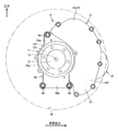
- FIG. 1 is a front view showing an in-wheel motor drive device.
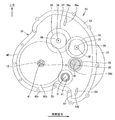
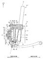
- FIG. 2 is a cross-sectional view schematically showing the in-wheel motor drive device. 1 and 2 show a state seen from the outside in the vehicle width direction. In FIG. 2, each gear in the speed reduction unit is represented by a tip circle, and individual teeth are omitted.
- FIG. 3 is a developed cross-sectional view schematically showing the in-wheel motor drive device.
- FIG. 3 includes a plane including the axis M and the axis Nf, a plane including the axis Nf and the axis Nl, a plane including the axis Nl and the axis O, an axis O and the axis P illustrated in FIG. It is the expansion
- the in-wheel motor drive device 10 includes a wheel hub bearing portion 11, a motor portion 21, and a speed reducing portion 31 that decelerates the rotation of the motor portion 21 and transmits it to the wheel hub bearing portion 11, and is an electric vehicle (not shown).
- a wheel hub bearing portion 11 is disposed on the outer side in the vehicle width direction
- the motor portion 21 is disposed on the inner side in the vehicle width direction
- the speed reducing portion 31 is disposed on the center portion in the vehicle width direction.
- the in-wheel motor drive device 10 is disposed in the inner space of the wheel wheel W represented by the phantom line in FIG. 1 and is connected to the center of the wheel wheel W represented by the phantom line in FIG.
- the wheel W is driven.
- tires are attached to the outer periphery of the wheel W.
- Each in-wheel motor drive device 10 is connected to a vehicle body of an electric vehicle via a suspension device (not shown).
- the in-wheel motor drive device 10 can drive an electric vehicle at a speed of 0 to 180 km / h on a public road.
- the motor part 21 and the speed reduction part 31 are not arranged coaxially with the axis O of the wheel hub bearing part 11 as shown in FIGS. 1 and 2, but are perpendicular to the axis O of the wheel hub bearing part 11 as shown in FIG. It is arranged offset.
- the in-wheel motor drive device 10 will be described in detail later, but a part disposed forward of the vehicle, a part disposed rearward of the vehicle, a part disposed above, and a part disposed below. including.
- the wheel hub bearing portion 11 includes a plurality of rollers disposed in an annular gap between the inner ring 12 as a hub ring coupled to the wheel wheel W, the non-rotating outer ring 13, and the inner ring 12 and the outer ring 13. It has the moving body 14 and the hub attachment 56, and comprises an axle.
- the inner ring 12 is longer than the outer ring 13 and is passed through the center hole of the outer ring 13 so that both ends of the inner ring 12 protrude from the outer ring 13.
- a flange portion 12f is formed at one end of the inner ring 12 in the axis O direction.
- An inner race 12r is attached and fixed to the outer periphery of the other end of the inner ring 12 in the axis O direction.
- the rolling elements 14 are arranged in double rows with a separation in the direction of the axis O.
- the outer peripheral surface of the central portion in the axis O direction of the inner ring 12 constitutes the inner raceway surface of the rolling elements 14 in the first row and faces the inner peripheral surface at one end of the outer ring 13 in the axis O direction.
- the outer circumferential surface of the inner race 12r constitutes the inner race surface of the second row of rolling elements 14, and faces the inner circumference at the other end of the outer race 13 in the axis O direction.
- the vehicle width direction outer side (outboard side) is also referred to as one axis O direction
- the vehicle width direction inner side (inboard side) is also referred to as the other axis O direction.
- the left-right direction in FIG. 3 corresponds to the vehicle width direction.
- the inner peripheral surface of the outer ring 13 constitutes the outer raceway surface of the rolling element 14.
- the flange portion 12f of the inner ring 12 is disposed on the outer side in the vehicle width direction with respect to the outer ring 13, and faces one end of the outer ring 13 in the axis O direction.
- the flange portion 12f constitutes a coupling seat portion for coupling coaxially with the brake disc BD and the spoke portion Ws of the wheel / wheel W.
- the inner ring 12 is coupled to the brake disc BD and the wheel wheel W at the flange portion 12f, and rotates integrally with the wheel wheel W.
- the flange portion 12f may be a protruding portion that protrudes toward the outer diameter side with an interval in the circumferential direction.
- a flange portion 13 f is formed on the outer ring 13.
- a hub attachment 56 is connected and fixed to the flange portion 13f with bolts 57.
- the hub attachment 56 has a through hole for receiving the outer ring 13 and plays a role of expanding the outer ring 13 to the outer diameter side.
- the bolt 57 is inserted into a round hole formed in the hub attachment 56 from the inner side in the axis O direction, and is screwed into a female screw hole formed in the flange portion 13f.
- the bolts 57 are arranged at equal intervals in the circumferential direction with the axis O as the center.
- the outer ring 13 is circular.
- the hub attachment 56 is a plate-like member including a circular portion 56c, an upper portion 56a projecting upward from the circular portion 56c, and a lower portion 56b projecting downward from the circular portion 56c as shown in FIG. 4A. is there.
- a main body casing 43 which will be described later, is attached and fixed to the circular portion 56c with a bolt (not shown).
- the upper portion 56a has, for example, a triangular shape with a tapered upper end.
- the lower portion 56b is, for example, a rectangle.
- the hub attachment 56 is formed with a female screw hole for connection with a main body casing 43 and a suspension bracket 61 described later.
- Each member of the wheel hub bearing portion 11 described so far is made of steel.
- the motor unit 21 includes a motor rotating shaft 22, a rotor 23, a stator 24, and a motor casing 25, which are sequentially arranged from the axis M of the motor unit 21 to the outer diameter side in this order.
- the motor unit 21 is a radial gap motor of an inner rotor and outer stator type, but may be of other types.
- the motor unit 21 may be an axial gap motor.
- the axis M that is the rotation center of the motor rotation shaft 22 and the rotor 23 extends in parallel with the axis O of the wheel hub bearing portion 11. That is, the motor unit 21 is disposed offset from the axis O of the wheel hub bearing unit 11. The axial position of the motor unit 21 does not overlap with the position of the outer ring 13 and the hub attachment 56 in the axial direction O as shown in FIG.
- the motor casing 25 has a substantially cylindrical shape.
- the motor casing 25 is coupled to the back surface portion 43b of the main body casing 43 at one end in the axis M direction, and is sealed with a bowl-shaped motor casing cover 25v at the other end in the axis M direction. Both end portions of the motor rotating shaft 22 are rotatably supported by the motor casing 25 via rolling bearings 27 and 28.
- the motor unit 21 drives the inner ring 12.
- the speed reduction unit 31 includes an input shaft 32, an input gear 33, an intermediate gear 34, an intermediate shaft 35, an intermediate gear 36, an intermediate gear 37, an intermediate shaft 38, an intermediate gear 39, an output gear 40, an output shaft 41, and a main body casing 43.
- the input shaft 32 is a cylindrical body having a larger diameter than the distal end portion 22 e of the motor rotation shaft 22, and extends along the axis M of the motor portion 21.
- the distal end portion 22 e is received in the center hole at the other end portion in the axis M direction of the input shaft 32, and the input shaft 32 is coupled coaxially with the motor rotation shaft 22. Both ends of the input shaft 32 are supported by the main body casing 43 via rolling bearings 42a and 42b.
- the input gear 33 is an external gear having a smaller diameter than the motor unit 21 and is coupled to the input shaft 32 coaxially.
- the input gear 33 is integrally formed on the outer periphery of the central portion of the input shaft 32 in the axis M direction.
- the output shaft 41 is a shaft having a smaller diameter than the inner ring 12, is coaxially coupled to the output gear 40, and extends along the axis O of the wheel hub bearing portion 11.
- the inner ring 12 has a cylindrical shape, and one end of the output shaft 41 in the axis O direction is inserted into the center hole at the other end of the inner ring 12 in the axis O direction, and the output shaft 41 is coupled to the inner ring 12 coaxially.
- a spline groove is formed on the outer peripheral surface of the output shaft 41
- a spline groove is formed on the inner peripheral surface of the other end of the inner ring 12 in the axis O direction, and these spline grooves are spline-fitted.
- the output gear 40 is an external gear and is coupled to the output shaft 41 coaxially. Specifically, the output gear 40 is integrally formed on the outer periphery of the other end of the output shaft 41 in the axis O direction.
- the two intermediate shafts 35 and 38 extend in parallel with the input shaft 32 and the output shaft 41. That is, the speed reduction unit 31 is a four-axis parallel shaft gear reducer, and the axis O of the output shaft 41, the axis Nf of the intermediate shaft 35, the axis Nl of the intermediate shaft 38, and the axis M of the input shaft 32 are parallel to each other. In other words, it extends in the vehicle width direction.
- each axis The vehicle longitudinal direction position of each axis will be described.
- the axis M of the input shaft 32 is arranged in front of the vehicle with respect to the axis O of the output shaft 41.
- the axis Nf of the intermediate shaft 35 is disposed in front of the vehicle with respect to the axis M of the input shaft 32.
- the axis Nl of the intermediate shaft 38 is arranged in front of the vehicle with respect to the axis O of the output shaft 41 and behind the axis M of the input shaft 32.
- the axis M of the input shaft 32 is arranged at an arbitrary position around the axis O, and the input shaft 32, the intermediate shaft 35, the intermediate shaft 38, and the output shaft 41 are arranged in this order in the vehicle longitudinal direction. It may be arranged.
- the vertical position of each axis is determined by the longitudinal position and vertical position of the motor unit 21.
- the shafts 32, 35, 38, and 41 constitute the driving force transmission order in this order.
- the axis M of the input shaft 32 and the axis O of the output shaft 41 are arranged at substantially the same vertical position.
- the axis Nf of the intermediate shaft 35 is disposed above the axis M of the input shaft 32.
- the axis Nl of the intermediate shaft 38 is disposed above the axis Nf of the intermediate shaft 35. It is sufficient that the plurality of intermediate shafts 35 and 38 are disposed above the input shaft 32 and the output shaft 41, and the intermediate shaft 35 may be disposed above the intermediate shaft 38 as a modification (not shown). Alternatively, as a modification not shown, the output shaft 41 may be disposed above the input shaft 32.
- the vertical positions of the input shaft 32, the intermediate shaft 35, the intermediate shaft 38, and the output shaft 41 are motors. Determined by the position in the front-rear direction and the position in the vertical direction.
- the intermediate gear 34 and the intermediate gear 36 are external gears, and are coupled coaxially with the central portion of the intermediate shaft 35 in the axis Nf direction as shown in FIG. Both ends of the intermediate shaft 35 are supported by the main body casing 43 via rolling bearings 45a and 45b. Specifically, one end of the intermediate shaft 35 in the axis Nf direction is supported by the front portion 43f via the rolling bearing 45a, and the other end of the intermediate shaft 35 in the axis Nf direction is supported by the back surface portion 43b via the rolling bearing 45b. .
- the intermediate gear 37 and the intermediate gear 39 are external gears, and are coupled coaxially with the central portion of the intermediate shaft 38 in the direction of the axis Nl.
- Both ends of the intermediate shaft 38 are supported by the main body casing 43 via rolling bearings 48a and 48b. Specifically, one end of the intermediate shaft 38 in the axis Nl direction is supported by the front portion 43f via the rolling bearing 48a, and the other end of the intermediate shaft 38 in the axis Nl direction is supported by the back surface portion 43b via the rolling bearing 48b. .
- the main body casing 43 forms an outer shell of the speed reduction part 31 and the wheel hub bearing part 11, is formed in a cylindrical shape, and surrounds axes O, Nf, Nl and M extending in parallel to each other as shown in FIG.
- the main body casing 43 is accommodated in the inner space of the wheel wheel W (FIG. 1).
- the inner space of the wheel W is partitioned by the inner peripheral surface of the rim portion Wr and the spoke portion Ws that is coupled to one end of the rim portion Wr in the axis O direction.
- One area in the axial direction of the wheel hub bearing portion 11, the speed reduction portion 31, and the motor portion 21 is accommodated in the inner space region of the wheel wheel W. Further, the other axial region of the motor unit 21 protrudes from the wheel W to the other axial direction.
- the wheel wheel W accommodates most of the in-wheel motor drive device 10.
- the main body casing 43 protrudes downward at a position away from the axis O of the output gear 40 in the longitudinal direction of the vehicle, specifically, directly below the axis M of the input gear 33.
- This protruding portion forms an oil tank 47.
- a space is secured between the portion 43c of the main body casing 43 directly below the axis O and the lower portion of the rim portion Wr.
- a suspension member (not shown) extending in the vehicle width direction is disposed in the space.
- the main body casing 43 has a cylindrical shape, and as shown in FIG. 3, the input shaft 32, the input gear 33, the intermediate gear 34, the intermediate shaft 35, the intermediate gear 36, the intermediate gear 37, the intermediate shaft 38, the intermediate gear 39, and the output gear. 40 and the output shaft 41 are accommodated. Lubricating oil is enclosed in the main body casing 43.
- the input gear 33, the intermediate gear 34, the intermediate gear 36, the intermediate gear 37, the intermediate gear 39, and the output gear 40 are helical gears that are lubricated and cooled by lubricating oil.
- the main body casing 43 has a substantially flat front portion 43 f that covers one side in the axial direction of the cylindrical portion of the speed reduction portion 31 and a substantially flat surface that covers the other side in the axial direction of the cylindrical portion of the speed reduction portion 31. It includes a back portion 43b.
- the back surface portion 43 b is coupled to the motor casing 25. Further, the back surface portion 43b is coupled to a suspension member (not shown) such as an arm or a damper via a suspension bracket 61 (FIG. 4A and the like) described later.
- a suspension member such as an arm or a damper via a suspension bracket 61 (FIG. 4A and the like) described later.
- the arms, dampers, and the like of the suspension device are also referred to as vehicle body side members because they are attached to the vehicle body side as viewed from the members to be described, here the in-wheel motor drive device 10. Since the main body casing 43, the motor casing 25, and the motor casing cover 25v are connected to the vehicle body side member via the suspension bracket, they are separated from the vehicle body side member.
- the small-diameter input gear 33 and the large-diameter intermediate gear 34 are arranged on one side (flange portion 12f side) in the axial direction of the speed reduction portion 31 and mesh with each other.
- the small-diameter intermediate gear 36 and the large-diameter intermediate gear 37 are disposed on the other side in the axial direction of the speed reduction unit 31 (on the motor unit 21 side) and mesh with each other.
- the small-diameter intermediate gear 39 and the large-diameter output gear 40 are arranged on one side in the axial direction (flange portion 12f side) of the speed reduction portion 31 and mesh with each other.
- the input gear 33, the plurality of intermediate gears 34, 36, 37, 39 and the output gear 40 mesh with each other, and the input gear 33 passes through the plurality of intermediate gears 34, 36, 37, 39 to the output gear 40.
- the rotation of the input shaft 32 is decelerated by the intermediate shaft 35
- the rotation of the intermediate shaft 35 is decelerated by the intermediate shaft 38
- the rotation of the intermediate shaft 38 is output by the meshing of the drive side small gear and the driven large diameter gear. Decelerated by the shaft 41.
- the deceleration part 31 ensures a sufficient reduction ratio.
- the intermediate gear 34 is a first intermediate gear positioned on the input side of the drive transmission path.
- the intermediate gear 39 is a final intermediate gear located on the output side of the drive transmission path.
- the output shaft 41, the intermediate shaft 38, and the input shaft 32 are arranged in this order with an interval in the vehicle front-rear direction. Further, the intermediate shaft 35 and the intermediate shaft 38 are disposed above the input shaft 32 and the output shaft 41. According to such an embodiment, the intermediate shaft can be disposed above the inner ring 12 that becomes the hub ring, and a space for arranging the oil tank 47 can be secured below the inner ring 12, or a space can be secured just below the inner ring 12. can do. Therefore, the turning axis extending in the vertical direction can be provided so as to intersect the space directly below the inner wheel 12, and the wheel wheel W and the in-wheel motor drive device 10 can be suitably turned around the turning axis.
- the input shaft 32 and the output shaft 41 extend in the vehicle width direction, and as shown in FIG. 2, the input gear 33 and the output gear 40 are set to stand up and down.
- the lower edge 40b of the output gear 40 is disposed below the lower edge 33b of the input gear 33.
- the plurality of intermediate shafts 35, 38 are arranged adjacent to each other above the input shaft 32 and are supplied with driving torque from the input shaft 32.
- a final intermediate shaft 38 that is disposed adjacent to the output shaft 41 and supplies driving torque to the output shaft 41, and includes the input shaft 32, the first intermediate shaft 35, the final intermediate shaft 38, and the output shaft 41.
- the reference lines sequentially connecting the centers of 41 (axis O) are arranged so as to draw an inverted U-shape.
- the main body casing 43 further accommodates a pump shaft 51, rolling bearings 52a and 52b, a pump gear 53, and an oil pump 54 as shown in FIG.
- the axis P of the pump shaft 51 extends in parallel with the axis O of the output shaft 41.
- the pump shaft 51 is disposed away from the output shaft 41 in the vehicle front-rear direction, is rotatably supported on both sides of the axis P direction via rolling bearings 52a and 52b, and is coaxial with the pump gear 53 at the center of the axis P direction.
- the pump gear 53 is an external gear, a helical gear, and meshes with the output gear 40 and is driven by the output gear 40.
- the oil pump 54 is disposed further on the other side in the axis P direction than the rolling bearing 52 b and is provided on the other end in the axis P direction of the pump shaft 51.
- the oil pump 54 is connected to the suction oil passage 59i and the discharge oil passage 59o shown in FIG.
- the suction oil passage 59 i extends downward from the oil pump and reaches the oil tank 47, and the suction port 59 j at the lower end of the suction oil passage 59 i is disposed near the bottom wall of the oil tank 47.
- the discharge oil passage 59 o extends upward from the oil pump, and the discharge port 59 p at the upper end of the discharge oil passage 59 o is disposed at a position higher than the intermediate gear 37.
- the oil pump 54 When the oil pump 54 is driven by the output gear 40, the oil pump 54 sucks the lubricating oil in the oil tank 47 from the suction port 59j, and discharges the sucked lubricating oil through the discharge port 59p.
- the discharge port 59p is positioned higher than all the gears (the input gear 33, the intermediate gears 34, 36, 37, 39, and the output gear 40), and supplies lubricating oil to these gears from above.
- Lubricating oil is injected into the motor unit 21 from the discharge oil passage 59o. Thereby, the motor part 21 and the deceleration part 31 are lubricated and cooled.
- the pump shaft 51 of the present embodiment is disposed below the input shaft 32, and the oil tank 47 is disposed below the pump shaft 51.
- the oil pump 54 is arranged substantially coaxially with the pump shaft 51 and pumps the lubricating oil stored in the oil tank 47 directly above the oil tank 47.
- the pump shaft 51 and the oil tank 47 are disposed in front of the output shaft 41 in the vehicle. When the wheel wheel W is driven by the in-wheel motor drive device 10 and the electric vehicle travels, the oil tank 47 receives the traveling wind from the front of the vehicle and is air-cooled.
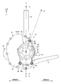
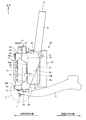
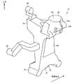
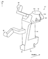
- FIG. 4A is a front view showing the in-wheel motor drive device according to the first embodiment of the present invention together with the suspension device, and shows a state viewed from the outside in the vehicle width direction.
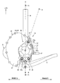
- FIG. 5 is a side view showing the first embodiment together with the suspension device, and shows a state viewed from the rear of the vehicle.
- FIG. 6A is a cross-sectional view showing the suspension bracket of the first embodiment, and shows a state in which the suspension bracket is cut along one plane indicated by AA in FIG. 4A and the cut surface is viewed in the direction of the arrow.
- 6B is a cross-sectional view showing the in-wheel motor drive device of the first embodiment, in which the in-wheel motor drive device is cut along two planes indicated by BB in FIG.
- FIG. 7A mainly shows the inner side in the vehicle width direction
- FIG. 7B mainly shows the outer side in the vehicle width direction.
- a suspension bracket 61 is attached to the main body casing 43 of this embodiment.
- the wheel hub bearing portion 11, the speed reduction portion 31, and the suspension bracket 61 are arranged in this order.
- the position of the suspension bracket 61 in the direction of the axis O overlaps the position of the motor unit 21 in the direction of the axis O.
- the motor part 21 and the speed reduction part 31 are disposed forward, and the wheel hub bearing part 11 and the suspension bracket 61 are disposed rearward.
- the suspension bracket 61 is a single member including an upper connection seat 62, an intermediate portion 63, a lower connection seat 64, and a protrusion 65.
- the upper connection seat 62 is provided at the upper end of the suspension bracket 61 and is connected to the upper suspension member, for example, the lower end of the strut 76.
- the strut 76 is a shock absorber that constitutes an upper suspension member of the strut suspension device and includes a damper extending in the vertical direction and a coil spring attached to the damper. In each drawing, only the damper outer cylinder of the strut 76 is shown, and the damper inner cylinder, coil spring, coil spring seat, and the like are omitted.
- the upper suspension member can be constituted by an upper arm or a plurality of links as another embodiment.
- the lower connection seat 64 is provided at the lower end of the suspension bracket 61 and is connected to the lower suspension member, for example, the outer end in the vehicle width direction of the lower arm 71.
- the lower arm 71 is an arm constituting the lower suspension member of the strut suspension device.
- the lower arm 71 extends in the vehicle width direction and is rotatably connected to a vehicle body side member such as a subframe at the vehicle width direction inner end, with the vehicle width direction inner end as a base end and the vehicle width direction outer end as a free end. It can swing in the vertical direction.
- the lower suspension member can be configured by a plurality of links as another embodiment.
- the intermediate portion 63 occupies the central region in the vertical direction of the suspension bracket 61 and connects the upper connecting seat 62 and the lower connecting seat 64.
- a plurality of projecting portions 65 are provided, and there are a projecting portion 65 projecting horizontally from the upper connecting seat portion 62 outward in the vehicle width direction and a projecting portion 65 projecting horizontally from the lower connecting seat portion 64 outward in the vehicle width direction. .
- one protrusion 65 is formed on the upper side.
- two protrusions 65 are formed on the lower side with a space in the vehicle front-rear direction.
- the upper connection seat 62, the intermediate portion 63, the lower connection seat 64, and the protrusion 65 are integrally formed.
- each protrusion 65 comes into contact with the hub attachment 56.
- the front end surface 65t of the upper protrusion 65 comes into contact with the abutting surface 56t formed to protrude inward in the vehicle width direction from the upper portion 56a of the hub attachment 56.
- the tip surface 65t of the lower protrusion 65 comes into contact with the abutting surface 56t of the lower portion 56b (FIG. 4A) of the hub attachment 56.
- the front end surface of each protrusion 65 is in contact with the other surface in the axis O direction of the hub attachment 56 at a position where it does not interfere with the main body casing 43.
- a female screw hole 66 is formed in each protrusion 65.
- Each female screw hole 66 is formed in the distal end surface 65t and extends parallel to the axis O.
- a plurality of round through holes 56 h are formed at positions corresponding to the respective female screw holes 66 in the hub attachment 56.
- Each through hole 56h is formed in the butting surface 56t and extends parallel to the axis O.
- the abutting surfaces 56t are provided at three locations so as to be separated from each other, but all are flush with each other. The same applies to each tip surface 65t.
- the butting surface 56t and the tip surface 65t are disposed between the rolling bearings 41a and 41b that are separated in the direction of the axis O.
- the intermediate portion 63 of the suspension bracket 61 overlaps the turning axis K when viewed in the vehicle longitudinal direction.
- the vehicle front-rear direction here is orthogonal to the axis O. 7A and 7B also intersect with the turning axis K.
- the suspension bracket 61 intersects the axis O.
- the lower female screw hole 66 and the front end face 65t are provided in front of the steering axis K and in the rear of the vehicle, respectively.
- FIG. 5 shows the stator core of the stator 24 by broken lines.
- the stator core is a laminated steel plate that is stacked in the axial direction of the motor unit 21.
- One end surface 24a in the axial direction of the stator core is directed outward in the vehicle width direction (outboard side), and the other end surface 24b in the axial direction of the stator core is directed inward in the vehicle width direction (inboard side).
- the suspension bracket 61 overlaps the stator 24 when viewed in the vehicle longitudinal direction.
- the position in the axis O direction of the suspension bracket 61 overlaps with the position in the axis O direction of the stator 24.
- the upper connecting seat portion 62 protrudes upward from the stator 24, and the lower connecting seat portion 64 protrudes downward from the stator 24.
- the vertical dimension of the suspension bracket 61 is larger than the diameter D of the tip circle of the output gear 40.
- the upper connecting seat 62 protrudes upward from the output gear 40, and the lower connecting seat 64 protrudes downward from the output gear 40.
- the female screw hole 66 and the through hole 56h coincide with each other, and a bolt 69 is passed through each through hole 56h of the hub attachment 56 from one side in the axis O direction.
- Each bolt 69 passes through one through hole 56h in the axis O direction and is screwed into the other female screw hole 66 in the axis O direction.
- the fixing means includes three bolts 69, three through holes 56 h that receive the respective bolts 69, and three female screw holes 66 that are screwed into the respective bolts 69.
- the bolts 69 and the like are not limited to a predetermined number, and a plurality of bolts 69 may be provided around the outer ring 13.
- the output shaft 41 is supplemented, and both end portions of the output shaft 41 are rotatably supported by the rolling bearings 41a and 41b, respectively.
- the rolling bearings 41 a and 41 b are arranged so as to sandwich the output gear 40.
- the rolling bearing 41a on the outer side in the vehicle width direction is attached to the front portion 43f.
- the rolling bearing 41b on the inner side in the vehicle width direction is attached to the back surface portion 43b.
- the abutting surface 56t and the front end surface 65t are arranged in a range R from the position in the axis O direction of the rolling bearing 41a to the position in the axis O direction of the rolling bearing 41b.
- the range R may include the dimension of the rolling bearings 41a and 41b itself in the direction of the axis O.
- the upper protrusion 65 is cantilevered by the upper connecting seat 62.
- the lower protrusion 65 is supported by the lower connection seat 64 in a cantilever manner.
- the hub attachment 56 is also formed with a protruding portion including a butting surface 56t at a position corresponding to each protruding portion 65.
- the protruding portion is also cantilevered by the hub attachment 56.
- the hub attachment 56 and the suspension bracket 61 define an opening V opened in the vehicle front-rear direction.
- the main body casing 43 is exposed from the opening V.
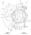
- FIG. 4B is a schematic diagram showing a modification of the in-wheel motor drive device, and shows the positional relationship between the rotating element of the in-wheel motor drive device and the suspension bracket as seen in the direction of the axis O.
- Each through hole 56 drilled in the hub attachment 56 coincides with each female screw hole 66 drilled in the suspension bracket 61.
- the hub attachment 56, the disc output gear 40, and the suspension bracket 61 overlap each other.
- Main casing 43 When connecting the centers of the through holes 56h with a straight line, a triangle ⁇ is obtained.
- Main casing 43 includes a region 43d in front of the vehicle relative to triangle ⁇ and a region 43k in the rear of the vehicle relative to triangle ⁇ .
- the region 43k supports a motor unit (not shown) on the inner side in the vehicle width direction.
- the number of through holes 56h may be a plurality of four or more, and the main body casing 43 may protrude forward and rearward of the vehicle as viewed from a polygon that connects adjacent through holes 56h with straight lines.
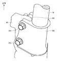
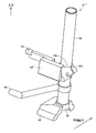
- FIG. 8 is an enlarged perspective view showing the upper part of the suspension bracket.
- FIG. 9 is a cross-sectional view showing the upper part of the suspension bracket, and shows a state in which the section is cut in the plane indicated by SS in FIG. In order to avoid complication, struts are omitted in FIG.
- the upper connection seat 62 of the suspension bracket 61 has a through-hole 62c having a circular cross section that opens upward.
- the cylindrical wall portion that defines the through-hole 62c is formed in a substantially C-shaped cross section with a slit (gap) 62d that opens in the circumferential direction.
- the upper connecting seat 62 is formed with a through hole 62f and a female screw hole 62g through which the bolt 62e is passed so as to extend in a line through the slit 62d.
- the upper connecting seat 62 is one member, and a connecting tool (bolt 62e) is attached.
- the upper connecting seat 62 may be made of two members, and a connecting tool may be additionally provided.
- FIG. 10 is a perspective view showing a modification of the upper part of the suspension bracket.
- FIG. 11 is a cross-sectional view showing a modification of FIG.
- the upper connection seat 62 of the modification includes a plate-like base 61i and a connection member 62j having a C-shaped cross section.
- the base 61i is inserted in the circumferential clearance of the connecting member 62j.
- the connecting member 62j is formed with a through hole and a female screw hole through which the bolt 62e is passed so as to extend in one row via a circumferential clearance.
- a through hole through which the bolt 62e is passed is also formed in the base 61i.
- the strut 76 is securely connected and fixed to the upper connecting seat 62 by passing the strut 76 through the central hole of the connecting member 62j and tightening the bolt 62e.
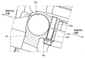
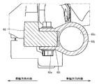
- FIG. 12 is a cross-sectional view showing the lower part of the suspension bracket, and shows an enlarged circled portion C indicated by a one-dot chain line in FIG.
- the socket 72s of the ball joint 72 is attached to the lower connection seat portion 64 of the suspension bracket 61 by the bolt 64b.
- the socket 72s has a downward opening.
- a ball stud 72 d of a ball joint 72 is erected on the lower arm 71.
- the ball stud 72d is nut-fastened at the lower end to the vehicle width direction outer end of the lower arm 71, and has a ball portion at the upper end.
- the ball portion of the ball stud 72d is slidably accommodated in the socket 72s.
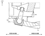
- FIG. 13 is a cross-sectional view showing a modification of the lower part of the suspension bracket. The difference from FIG. 12 is that the ball joint 72 is provided upside down.
- the suspension bracket 61 further includes a tie rod arm 67.
- the tie rod arm 67 is disposed at the rear portion of the intermediate portion 63 and is integrally formed with the intermediate portion 63.
- the tie rod arm 67 extends rearward as shown in FIG. 4A.
- a tie rod coupling seat such as a round hole for receiving a ball joint is formed.
- a tie rod (not shown) is coupled to the tie rod coupling seat at the tip of the tie rod arm 67.
- the in-wheel motor drive device 10 including the suspension bracket 61 is steered together with the wheels.
- the turning axis K that is the center of turning is a straight line that passes through the upper end of the strut 76 and the ball joint 72 and extends in the vertical direction.
- the main body casing 43 is made of light metal, for example, a casting mainly composed of aluminum.
- the suspension bracket 61 and the hub attachment 56 are made of steel, and have higher rigidity than the main body casing 43.
- the present embodiment includes a bolt 69, a round through hole 56h, and a female screw hole 66 as fixing means.
- the members for attaching the in-wheel motor drive device to the suspension device are concentrated on the suspension bracket 61.
- the suspension bracket 61 is attached and fixed to the hub attachment 56 of the wheel hub bearing portion 11. Thereby, even if an excessive external force is applied to the wheel hub bearing portion 11 from the wheel side, the suspension bracket 61 can receive the excessive external force and escape to the suspension device. Therefore, an excessive external force is not transmitted to the main body casing 43 of the speed reduction part 31, and the speed reduction part 31 can be protected so that undesired deformation does not occur in the speed reduction part 31.
- FIG. 14 is a perspective view showing a suspension bracket of a first modification.
- the suspension bracket 61 of the first modified example omits the tie rod arm. Instead, the tie rod arm is formed integrally with the main body casing 43, for example.
- the suspension bracket 61 of the first modification further includes two brake caliper arms 68.
- One brake caliper arm 68 is integrally formed with the intermediate portion 63 of the suspension bracket 61, and the other brake caliper arm 68 is integrally formed with the upper connecting seat portion 62.
- FIG. 4A when the suspension bracket 61 is attached and fixed to the inner portion in the vehicle width direction of the in-wheel motor drive device 10, one brake caliper arm 68 extends to the rear of the vehicle, and the other brake caliper arms 68 move upward. Extend.
- Brake caliper coupling seats such as female screw holes (not shown) for receiving bolts are formed at the tip of each brake caliper arm 68.
- a brake caliper (not shown) is connected to the brake caliper connecting seat at the tip of each brake caliper arm 68, and the two brake caliper arms 68 support the brake caliper in both ends.
- the brake caliper is disposed along the outer edge of the brake disc BD (FIG. 3), and brakes the wheel (wheel wheel W) by clamping the brake disc BD.
- the brake caliper may be driven by hydraulic pressure, or may be driven by an electric actuator, and the mechanism is not particularly limited.
- the suspension bracket 61 may include a tie rod arm 67 and a brake caliper arm 68.
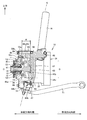
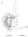
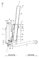
- FIG. 15 is a front view showing the in-wheel motor drive device according to the second embodiment of the present invention together with the suspension device, and shows a state seen from the outside in the vehicle width direction.
- FIG. 16 is a side view showing the second embodiment together with the suspension device, and shows a state seen from the rear of the vehicle.
- FIG. 17A is a cross-sectional view showing the suspension bracket of the second embodiment, showing a state in which the suspension bracket is cut along one plane indicated by AA in FIG. 15 and the cut surface is viewed in the direction of the arrow.
- FIG. 17B is a cross-sectional view showing the in-wheel motor drive device of the second embodiment, in which the in-wheel motor drive device is cut along two planes indicated by BB in FIG.
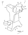
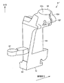
- FIG. 18 is a perspective view showing the suspension bracket taken out from the second embodiment.
- symbol is attached
- the bolt 69 of the second embodiment is common to the first embodiment in that the suspension bracket 61 ′ is connected and fixed to the hub attachment 56.
- the bolt 69 as a fixing means is different from the second embodiment in that the suspension bracket 61 ′, the hub attachment 56, and the main body casing 43 are connected and fixed together.
- the main body casing 43 is composed of two members, a front portion 43f and a back portion 43b.
- a through hole 43h which is a round hole, is formed in the front portion 43f.
- a through hole 43i that is a round hole is formed in the back surface portion 43b.
- the portion of the front portion 43f where the through hole 43h is formed contacts the other surface of the hub attachment 56 in the axis O direction.
- a portion of the back surface portion 43b where the through hole 43i is formed contacts one surface of the suspension bracket 61 in the axis O direction.
- the through hole 56h of the hub attachment 56, the through hole 43h of the front portion 43f, the through hole 43i of the back portion 43b, and the female screw hole 66 of the suspension bracket 61 are aligned with each other in this order and parallel to the axis O. Extend.
- Bolts 69 communicate with each through hole 56h of the hub attachment 56 from one side in the axis O direction.
- Each bolt 69 sequentially passes through one through hole 56h in the axis O direction and through holes 43h and 43i in the central portion in the axis O direction, and is screwed into the other female screw hole 66 in the axis O direction.
- the hub attachment 56, the front portion 43f, the back portion 43b, and the suspension bracket 61 are fastened together.
- fixing means three bolts 69, three through holes 56h for receiving the bolts 69, three through holes 43h for receiving the bolts 69, and three through holes for receiving the bolts 69 are provided. It has a hole 43i and three female screw holes 66 that are screwed into the respective bolts 69.
- the bolts 69 and the like are not limited to a predetermined number, and a plurality of bolts 69 may be provided around the outer ring 13.
- FIG. 19 is a perspective view showing a suspension bracket of a second modified example.
- the suspension bracket 61 ′ of the second modified example omits the tie rod arm. Instead, the tie rod arm is formed integrally with the main body casing 43, for example.
- the suspension bracket 61 ′ of the second modified example further includes two brake caliper arms 68.
- One brake caliper arm 68 is formed integrally with the intermediate portion 63 of the suspension bracket 61.
- the other brake caliper arm 68 is integrally formed with the upper connecting seat portion 62.
- one brake caliper arm 68 extends to the rear of the vehicle, and the other brake caliper arm 68 moves upward. Extend to.
- Brake caliper coupling seats such as female screw holes (not shown) for receiving bolts are formed at the tip of each brake caliper arm 68.
- a brake caliper (not shown) is connected to the brake caliper connecting seat at the tip of each brake caliper arm 68, and the two brake caliper arms 68 support the brake caliper in both ends.
- the brake caliper is disposed along the outer edge of the brake disc BD (FIG. 3), and brakes the wheel (wheel wheel W) by clamping the brake disc BD.
- the brake caliper may be driven by hydraulic pressure, or may be driven by an electric actuator, and the mechanism is not particularly limited.
- the suspension bracket 61 ′ may include a tie rod arm 67 and a brake caliper arm 68.
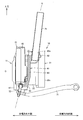
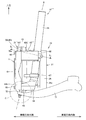
- FIG. 20 is a front view showing the in-wheel motor drive device according to the third embodiment of the present invention together with the suspension device, and shows a state seen from the outside in the vehicle width direction.
- FIG. 21 is a side view showing the third embodiment together with the suspension device, and shows a state seen from the rear of the vehicle.
- FIG. 22A is a sectional view showing the suspension bracket of the third embodiment, and shows a state in which the suspension bracket is cut along one plane indicated by AA in FIG. 20 and the cut surface is viewed in the direction of the arrow.
- FIG. 22B is a cross-sectional view showing the in-wheel motor drive device of the second embodiment, in which the in-wheel motor drive device is cut along two planes indicated by BB in FIG.
- FIG. 23 is a perspective view showing the suspension bracket taken out from the third embodiment.
- the same components as those in the above-described embodiment are denoted by the same reference numerals, description thereof is omitted, and different configurations are described below.
- the suspension bracket 61 ′′ of the third embodiment includes a damper outer cylinder 76t, a lower connecting seat portion 64, a protruding portion 65, and a block 65 ′′.
- the suspension bracket 61 of the first embodiment and the suspension bracket 61 ′ of the second embodiment are one member
- the suspension bracket 61 ′′ of the third embodiment is composed of a damper outer cylinder 76 t and a lower connection seat as separate members. This is an assembly in which the portion 64 and the block 65 ′′ are combined.
- the damper outer cylinder 76t is a component of the damper and extends in the vertical direction.
- the lower connecting seat portion 64 is attached and fixed to the lower end portion of the damper outer cylinder 76t.
- the protruding portion 65 is integrally formed with the lower connecting seat portion 64 and protrudes outward from the lower connecting seat portion 64 in the vehicle width direction.
- the block 65 ′′ is attached and fixed to the outer periphery of the damper outer cylinder 76t above the lower connecting seat portion 64. As shown in FIG.
- the block 65 ′′ extends in the vehicle width direction, has a female screw hole 66 on the outer end surface in the vehicle width direction, and has a through hole 62c, a slit 62d, a bolt 62e, a through hole 62f on the inner end in the vehicle width direction. It has a female screw hole 62g (FIGS. 8 and 9).
- a damper outer cylinder 76t is passed through the through hole 62c, and the damper outer cylinder 76t is attached and fixed by tightening the bolt 62e.
- the outer end surface in the vehicle width direction of the block 65 ′′ is in contact with the other surface of the hub attachment 56 in the axis O direction.
- the hub attachment 56 is connected and fixed to the block 65 ′′ by a bolt 69.
- the main body casing 43 is connected and fixed to the hub attachment 56 by bolts (not shown).
- the suspension bracket 61 ′′ further includes a tie rod arm 67.
- the tie rod arm 67 is attached and fixed to the outer periphery of the damper outer cylinder 76t above the lower connecting seat portion 64 and below the block 65 ′′.
- FIG. 24 is a perspective view showing a suspension bracket of a third modified example.
- the suspension bracket 61 ′′ of the third modified example omits the tie rod arm. Instead, the tie rod arm is formed integrally with the main body casing 43, for example.
- the suspension bracket 61 ′′ of the third modified example further includes two brake caliper arms 68.
- One brake caliper arm 68 is formed integrally with the block 65 ′′.
- the other brake caliper arm 68 is attached and fixed to the outer peripheral surface of the damper outer cylinder 76t.
- one brake caliper arm 68 extends rearward of the vehicle, and the other brake caliper arms 68 are Extends upward.
- Brake caliper coupling seats such as female screw holes (not shown) for receiving bolts are formed at the tip of each brake caliper arm 68.
- a brake caliper (not shown) is connected to the brake caliper connecting seat at the tip of each brake caliper arm 68, and the two brake caliper arms 68 support the brake caliper in both ends.
- the brake caliper is disposed along the outer edge of the brake disc BD (FIG. 3), and brakes the wheel (wheel wheel W) by clamping the brake disc BD.
- the brake caliper may be driven by hydraulic pressure, or may be driven by an electric actuator, and the mechanism is not particularly limited.
- the suspension bracket 61 ′′ may include a tie rod arm 67 and a brake caliper arm 68.
- the strut 76 of the suspension device includes a damper.
- the suspension bracket 61 includes an upper connecting seat 62 that can be connected to the strut 76, a lower connecting seat 64 that can be connected to the lower arm 71 of the suspension device, and an intermediate connecting the upper connecting seat 62 and the lower connecting seat 64. It has a portion 63.
- a bolt 69 as a fixing means attaches and fixes the suspension bracket 61 to the hub attachment 56. Thereby, even if an excessive external force is applied to the wheel hub bearing portion 11 from the wheel side, the suspension bracket 61 can receive the excessive external force and transmit it to the suspension device. Therefore, an excessive external force is not transmitted to the main body casing 43, and it is possible to protect the in-wheel motor drive device 10 from being undesirably deformed.
- the main body casing 43 is interposed between the hub attachment 56 and the suspension bracket 61, and the suspension bracket 61 has a protrusion 65 that extends toward the wheel hub bearing portion 11 and contacts the hub attachment 56.
- the bolt 69 as a fixing means attaches and fixes the protrusion 65 to the hub attachment 56.
- an excessive external force can be directly transmitted from the wheel hub bearing portion 11 to the suspension bracket 61.
- the wheel hub bearing portion 11, the main body casing 43, and the suspension bracket 61 can be arranged in this order.
- the reduction gears 31 are respectively disposed on one side and the other side of the output gear 40 in the axis O direction, and are rolling bearings 41 a and 41 b that rotatably support the output gear 40.
- the tip surface 65t of the protrusion 65 is included in a range R in which the position of the tip surface 65t in the axis O direction is included in the range R from the rolling bearing 41a on one side of the axis O direction to the rolling bearing 41b on the other side of the axis O direction. Be placed.
- the suspension bracket 61 and the hub attachment 56 define an opening V that opens in the direction perpendicular to the axis O therebetween, and the main body casing 43 is exposed from the opening V. .
- the main body casing 43 is interposed between the hub attachment 56 and the suspension bracket 61, and the fixing means is the suspension bracket 61 aligned in the direction of the axis O, the main body casing 43, and the bolt passing through the hub attachment 56. 69.
- the means for fixing the main body casing 43 to the wheel hub bearing portion 11 can be omitted.
- the bolts 69 passed through the suspension bracket 61 and the hub attachment 56 are included as fixing means, and there are three or more bolts 69 as shown in FIG. Are arranged above and below the axis O of the.
- the main body casing 43 is formed so as to protrude from the region of the triangle ⁇ connecting the adjacent bolts 69 with a straight line to the front and rear of the vehicle in a plane perpendicular to the axis O.
- the suspension bracket 61 and the turning axis K are arranged so as to overlap each other when viewed in the vehicle longitudinal direction.
- the bolts 69 are arranged in front of the vehicle and behind the steering axis K.
- the three members of the hub attachment 46, the output gear 40, and the suspension bracket 61 are arranged so as to overlap each other when viewed in the direction of the axis O.
- the overlap mentioned here means the overlap of 3 members, and is not the overlap of any 2 members.
- the suspension bracket 61 and the stator 24 of the motor unit 21 are arranged so as to overlap each other when viewed in the vehicle longitudinal direction.
- the suspension bracket 61 ′′ extends in the vertical direction, the damper outer cylinder 76t, the lower connection seat 64 that is provided at the lower end of the damper outer cylinder 76t and can be connected to the lower arm 71, and the damper. It has a block 65 ′′ provided on the outer periphery of the outer cylinder 76t. As a result, the degree of freedom of the suspension device is increased by using the block 65 ′′ as a separate member from the lower connecting seat portion 64. Further, it is possible to lengthen the damper downward and bring the lower end of the damper outer cylinder 76t closer to the lower arm 71.
- the suspension brackets 61, 61 ′, 61 ′′ further include the tie rod arm 67, and the tie rod connection for connecting the tie rod arm 67 to the tie rod of the steering device is provided at the tip of the tie rod arm 67.
- a seat is formed. Thereby, the in-wheel motor drive device 10 can be steered.
- the suspension brackets 61, 61 ′, 61 ′′ further include the brake caliper arm 68, and the brake caliper for connecting to the brake caliper is provided at the tip of the brake caliper arm 68.
- a connecting seat is formed.
- the in-wheel motor drive device according to the present invention is advantageously used in electric vehicles and hybrid vehicles.
Landscapes
- Engineering & Computer Science (AREA)
- Mechanical Engineering (AREA)
- Chemical & Material Sciences (AREA)
- Combustion & Propulsion (AREA)
- Transportation (AREA)
- Arrangement Or Mounting Of Propulsion Units For Vehicles (AREA)
- Vehicle Body Suspensions (AREA)
Priority Applications (3)
| Application Number | Priority Date | Filing Date | Title |
|---|---|---|---|
| EP17855923.3A EP3521088A4 (en) | 2016-09-30 | 2017-09-21 | MOTOR-WHEEL DRIVE DEVICE |
| US16/334,877 US10889178B2 (en) | 2016-09-30 | 2017-09-21 | In-wheel motor drive device |
| CN201780060313.8A CN109789768A (zh) | 2016-09-30 | 2017-09-21 | 轮内电动机驱动装置 |
Applications Claiming Priority (2)
| Application Number | Priority Date | Filing Date | Title |
|---|---|---|---|
| JP2016-193755 | 2016-09-30 | ||
| JP2016193755A JP6823418B2 (ja) | 2016-09-30 | 2016-09-30 | インホイールモータ駆動装置 |
Publications (1)
| Publication Number | Publication Date |
|---|---|
| WO2018061968A1 true WO2018061968A1 (ja) | 2018-04-05 |
Family
ID=61759740
Family Applications (1)
| Application Number | Title | Priority Date | Filing Date |
|---|---|---|---|
| PCT/JP2017/034060 Ceased WO2018061968A1 (ja) | 2016-09-30 | 2017-09-21 | インホイールモータ駆動装置 |
Country Status (5)
| Country | Link |
|---|---|
| US (1) | US10889178B2 (OSRAM) |
| EP (1) | EP3521088A4 (OSRAM) |
| JP (1) | JP6823418B2 (OSRAM) |
| CN (1) | CN109789768A (OSRAM) |
| WO (1) | WO2018061968A1 (OSRAM) |
Cited By (1)
| Publication number | Priority date | Publication date | Assignee | Title |
|---|---|---|---|---|
| EP3858649A4 (en) * | 2018-09-27 | 2022-03-30 | NTN Corporation | BRAKING STRUCTURE FOR MOTOR-WHEEL DRIVE DEVICE |
Families Citing this family (7)
| Publication number | Priority date | Publication date | Assignee | Title |
|---|---|---|---|---|
| JP6792995B2 (ja) * | 2016-03-14 | 2020-12-02 | Ntn株式会社 | インホイールモータ駆動装置 |
| JP6823417B2 (ja) * | 2016-09-30 | 2021-02-03 | Ntn株式会社 | インホイールモータ駆動装置 |
| JP7103173B2 (ja) * | 2018-11-05 | 2022-07-20 | トヨタ自動車株式会社 | サスペンション装置、車両 |
| KR102138687B1 (ko) * | 2019-05-27 | 2020-07-28 | 주식회사 센트랄 | 스트러트 현가장치 |
| IT201900017300A1 (it) * | 2019-09-26 | 2021-03-26 | Amer Spa | Struttura di motoruota perfezionata |
| CN114506197B (zh) * | 2022-03-23 | 2022-11-29 | 无锡泓阳电动科技有限公司 | 一种新能源汽车用电机便携安装结构及新能源汽车用电机 |
| CN117863866B (zh) * | 2024-03-11 | 2024-05-24 | 浙江创大汽车部件有限公司 | 一种羊角型汽车轮毂电驱动装置 |
Citations (8)
| Publication number | Priority date | Publication date | Assignee | Title |
|---|---|---|---|---|
| JPH10304645A (ja) * | 1997-04-21 | 1998-11-13 | Toyota Motor Corp | モータおよびホイールモータ |
| JP2004175175A (ja) * | 2002-11-26 | 2004-06-24 | Nissan Motor Co Ltd | 車輪用回転電機の取付構造 |
| JP2011105068A (ja) * | 2009-11-13 | 2011-06-02 | Ntn Corp | インホイールモータ駆動装置 |
| JP2013126280A (ja) * | 2011-12-14 | 2013-06-24 | Nissan Motor Co Ltd | 回転電機 |
| JP2013226994A (ja) * | 2012-04-27 | 2013-11-07 | Ntn Corp | インホイールモータ駆動装置 |
| JP2015128960A (ja) * | 2014-01-08 | 2015-07-16 | Ntn株式会社 | インホイールモータ駆動装置のサスペンション構造 |
| JP6125083B1 (ja) * | 2016-10-17 | 2017-05-10 | Ntn株式会社 | インホイールモータ駆動装置 |
| JP2017171272A (ja) * | 2016-03-22 | 2017-09-28 | Ntn株式会社 | インホイールモータ駆動装置 |
Family Cites Families (39)
| Publication number | Priority date | Publication date | Assignee | Title |
|---|---|---|---|---|
| US4109391A (en) | 1977-01-10 | 1978-08-29 | Sperry Rand Corporation | Portable surveying compass with flux valve and gyrocompass alignment modes |
| US5127485A (en) * | 1988-06-29 | 1992-07-07 | Aisin Aw Co., Ltd. | Electric motorized wheel with integral motorized cooling oil pump |
| DE4120262B4 (de) * | 1990-11-20 | 2007-03-22 | Aisin AW Co., Ltd., Anjo | Radmotor mit einem Untersetzungsgetriebe |
| US5150763A (en) * | 1991-04-24 | 1992-09-29 | Aisin Aw Co., Ltd. | Wiring and piping arrangement for a vehicle motor |
| US5087229A (en) * | 1991-05-06 | 1992-02-11 | General Motors Corporation | Independently suspended steerable motor wheel apparatus |
| SE516990C2 (sv) * | 1998-12-29 | 2002-04-02 | Volvo Car Corp | Arrangemang för hjulupphängning i fordon |
| JP4133186B2 (ja) * | 2002-10-02 | 2008-08-13 | 株式会社ブリヂストン | 操舵輪用インホイールモータシステム |
| JP4225134B2 (ja) * | 2003-06-25 | 2009-02-18 | トヨタ自動車株式会社 | 車両用懸架装置 |
| JP2005081872A (ja) * | 2003-09-04 | 2005-03-31 | Toyota Motor Corp | インホイールモータ |
| US7703780B2 (en) * | 2003-09-30 | 2010-04-27 | Toyota Jidosha Kabushiki Kaisha | Wheel supporting apparatus improving ride comfort of vehicle |
| JP4276579B2 (ja) * | 2004-05-17 | 2009-06-10 | トヨタ自動車株式会社 | インホイールモータに設けられる部品の搭載構造 |
| JP4139353B2 (ja) * | 2004-05-25 | 2008-08-27 | トヨタ自動車株式会社 | 車輪支持装置 |
| JP2006188153A (ja) * | 2005-01-06 | 2006-07-20 | Toyota Motor Corp | インホイールモータ |
| JP2007161022A (ja) * | 2005-12-12 | 2007-06-28 | Bridgestone Corp | インホイールモータシステム |
| US7537223B2 (en) * | 2005-12-12 | 2009-05-26 | Ford Global Technologies, Llc | Vehicle wheel suspension assembly |
| JP4965131B2 (ja) * | 2006-01-27 | 2012-07-04 | トヨタ自動車株式会社 | インホイールモータ |
| US8002060B2 (en) * | 2006-02-17 | 2011-08-23 | Honda Motor Co., Ltd. | Vehicle wheel driving apparatus and electric motor |
| WO2007102545A1 (ja) * | 2006-03-08 | 2007-09-13 | Ntn Corporation | インホイールモータ駆動装置 |
| JP4820189B2 (ja) * | 2006-03-09 | 2011-11-24 | 本田技研工業株式会社 | 車両用ホイール駆動装置の配置構造 |
| JP3960553B1 (ja) * | 2006-03-31 | 2007-08-15 | 本田技研工業株式会社 | インホイールモータ車のホイール回転装置 |
| JP4438779B2 (ja) * | 2006-08-11 | 2010-03-24 | トヨタ自動車株式会社 | インホイールモータ構造 |
| JP4238894B2 (ja) * | 2006-08-11 | 2009-03-18 | トヨタ自動車株式会社 | モータ及びこれを用いたインホイールモータ構造 |
| JP4758852B2 (ja) * | 2006-08-29 | 2011-08-31 | 本田技研工業株式会社 | ホイール回転装置のブレーキ構造 |
| JP5163206B2 (ja) * | 2008-03-19 | 2013-03-13 | アイシン精機株式会社 | インホイールモータシステム |
| WO2011058844A1 (ja) * | 2009-11-13 | 2011-05-19 | Ntn株式会社 | インホイールモータ駆動装置 |
| JP5374333B2 (ja) * | 2009-11-27 | 2013-12-25 | Ntn株式会社 | インホイールモータ駆動装置 |
| JP5517869B2 (ja) * | 2009-11-27 | 2014-06-11 | Ntn株式会社 | インホイール型モータ内蔵センサ付き車輪用軸受装置 |
| JP5565388B2 (ja) * | 2011-03-28 | 2014-08-06 | アイシン・エィ・ダブリュ株式会社 | インホイールモータ駆動装置 |
| JP5809927B2 (ja) * | 2011-10-28 | 2015-11-11 | Ntn株式会社 | インホイールモータ駆動装置 |
| EP2993066B1 (en) * | 2013-04-30 | 2018-09-05 | Nissan Motor Co., Ltd | Suspension device for in-wheel motor driven wheel |
| JP6112194B2 (ja) * | 2013-04-30 | 2017-04-12 | 日産自動車株式会社 | インホイールモータ駆動車輪用サスペンション装置 |
| JP6313610B2 (ja) * | 2014-02-27 | 2018-04-18 | Ntn株式会社 | インホイールモータ駆動装置とダンパとの連結構造およびこの連結構造を備えるサスペンション装置 |
| JP6347149B2 (ja) | 2014-05-12 | 2018-06-27 | トヨタ自動車株式会社 | インホイールモータユニット |
| JP6853622B2 (ja) * | 2015-09-29 | 2021-03-31 | Ntn株式会社 | インホイールモータ駆動装置、およびインホイールモータ駆動装置とサスペンション装置の連結構造 |
| JP6125066B1 (ja) * | 2016-03-08 | 2017-05-10 | Ntn株式会社 | インホイールモータ駆動装置 |
| JP6918459B2 (ja) * | 2016-04-06 | 2021-08-11 | Ntn株式会社 | インホイールモータ動力線の配線構造およびインホイールモータ駆動装置 |
| JP6334590B2 (ja) * | 2016-04-06 | 2018-05-30 | Ntn株式会社 | インホイールモータ駆動装置 |
| JP2017185912A (ja) * | 2016-04-06 | 2017-10-12 | Ntn株式会社 | インホイールモータ動力線の配線構造およびインホイールモータ駆動装置 |
| JP7024595B2 (ja) * | 2018-05-16 | 2022-02-24 | トヨタ自動車株式会社 | 車輪駆動ユニット |
-
2016
- 2016-09-30 JP JP2016193755A patent/JP6823418B2/ja not_active Expired - Fee Related
-
2017
- 2017-09-21 US US16/334,877 patent/US10889178B2/en not_active Expired - Fee Related
- 2017-09-21 CN CN201780060313.8A patent/CN109789768A/zh active Pending
- 2017-09-21 EP EP17855923.3A patent/EP3521088A4/en not_active Withdrawn
- 2017-09-21 WO PCT/JP2017/034060 patent/WO2018061968A1/ja not_active Ceased
Patent Citations (8)
| Publication number | Priority date | Publication date | Assignee | Title |
|---|---|---|---|---|
| JPH10304645A (ja) * | 1997-04-21 | 1998-11-13 | Toyota Motor Corp | モータおよびホイールモータ |
| JP2004175175A (ja) * | 2002-11-26 | 2004-06-24 | Nissan Motor Co Ltd | 車輪用回転電機の取付構造 |
| JP2011105068A (ja) * | 2009-11-13 | 2011-06-02 | Ntn Corp | インホイールモータ駆動装置 |
| JP2013126280A (ja) * | 2011-12-14 | 2013-06-24 | Nissan Motor Co Ltd | 回転電機 |
| JP2013226994A (ja) * | 2012-04-27 | 2013-11-07 | Ntn Corp | インホイールモータ駆動装置 |
| JP2015128960A (ja) * | 2014-01-08 | 2015-07-16 | Ntn株式会社 | インホイールモータ駆動装置のサスペンション構造 |
| JP2017171272A (ja) * | 2016-03-22 | 2017-09-28 | Ntn株式会社 | インホイールモータ駆動装置 |
| JP6125083B1 (ja) * | 2016-10-17 | 2017-05-10 | Ntn株式会社 | インホイールモータ駆動装置 |
Non-Patent Citations (1)
| Title |
|---|
| See also references of EP3521088A4 * |
Cited By (1)
| Publication number | Priority date | Publication date | Assignee | Title |
|---|---|---|---|---|
| EP3858649A4 (en) * | 2018-09-27 | 2022-03-30 | NTN Corporation | BRAKING STRUCTURE FOR MOTOR-WHEEL DRIVE DEVICE |
Also Published As
| Publication number | Publication date |
|---|---|
| EP3521088A1 (en) | 2019-08-07 |
| US20200016972A1 (en) | 2020-01-16 |
| US10889178B2 (en) | 2021-01-12 |
| CN109789768A (zh) | 2019-05-21 |
| EP3521088A4 (en) | 2020-05-20 |
| JP6823418B2 (ja) | 2021-02-03 |
| JP2018052424A (ja) | 2018-04-05 |
Similar Documents
| Publication | Publication Date | Title |
|---|---|---|
| WO2018061968A1 (ja) | インホイールモータ駆動装置 | |
| JP6125083B1 (ja) | インホイールモータ駆動装置 | |
| JP2017171272A (ja) | インホイールモータ駆動装置 | |
| JP6792995B2 (ja) | インホイールモータ駆動装置 | |
| JP6853622B2 (ja) | インホイールモータ駆動装置、およびインホイールモータ駆動装置とサスペンション装置の連結構造 | |
| JP6823417B2 (ja) | インホイールモータ駆動装置 | |
| JP6706517B2 (ja) | インホイールモータ駆動装置とサスペンション装置の連結構造 | |
| JP6714463B2 (ja) | インホイールモータ駆動装置、およびインホイールモータ駆動装置と車輪の連結構造 | |
| WO2018135470A1 (ja) | インホイールモータ駆動装置 | |
| WO2018070055A1 (ja) | インホイールモータ駆動装置 | |
| US20220048317A1 (en) | Braking structure for in-wheel motor drive device | |
| JP6781608B2 (ja) | インホイールモータ駆動装置 | |
| JP2018043574A (ja) | インホイールモータ駆動装置 | |
| JP7270403B2 (ja) | インホイールモータ駆動装置 | |
| JP2020093615A (ja) | インホイールモータ駆動装置 | |
| JP2014125041A (ja) | 車軸連結装置及び車両用駆動装置 | |
| JP6757630B2 (ja) | インホイールモータ駆動装置 | |
| WO2017163480A1 (ja) | インホイールモータ駆動装置 | |
| WO2017158933A1 (ja) | インホイールモータ駆動装置 | |
| JP2019059394A (ja) | インホイールモータ駆動装置 |
Legal Events
| Date | Code | Title | Description |
|---|---|---|---|
| 121 | Ep: the epo has been informed by wipo that ep was designated in this application |
Ref document number: 17855923 Country of ref document: EP Kind code of ref document: A1 |
|
| NENP | Non-entry into the national phase |
Ref country code: DE |
|
| ENP | Entry into the national phase |
Ref document number: 2017855923 Country of ref document: EP Effective date: 20190430 |