WO2017183505A1 - 作業装置および双腕型作業装置 - Google Patents
作業装置および双腕型作業装置 Download PDFInfo
- Publication number
- WO2017183505A1 WO2017183505A1 PCT/JP2017/014683 JP2017014683W WO2017183505A1 WO 2017183505 A1 WO2017183505 A1 WO 2017183505A1 JP 2017014683 W JP2017014683 W JP 2017014683W WO 2017183505 A1 WO2017183505 A1 WO 2017183505A1
- Authority
- WO
- WIPO (PCT)
- Prior art keywords
- link
- end side
- hub
- rotation
- working device
- Prior art date
Links
Images


Classifications
-
- B—PERFORMING OPERATIONS; TRANSPORTING
- B25—HAND TOOLS; PORTABLE POWER-DRIVEN TOOLS; MANIPULATORS
- B25J—MANIPULATORS; CHAMBERS PROVIDED WITH MANIPULATION DEVICES
- B25J17/00—Joints
- B25J17/02—Wrist joints
- B25J17/0283—Three-dimensional joints
-
- B—PERFORMING OPERATIONS; TRANSPORTING
- B25—HAND TOOLS; PORTABLE POWER-DRIVEN TOOLS; MANIPULATORS
- B25J—MANIPULATORS; CHAMBERS PROVIDED WITH MANIPULATION DEVICES
- B25J9/00—Programme-controlled manipulators
- B25J9/0009—Constructional details, e.g. manipulator supports, bases
- B25J9/0018—Bases fixed on ceiling, i.e. upside down manipulators
-
- B—PERFORMING OPERATIONS; TRANSPORTING
- B25—HAND TOOLS; PORTABLE POWER-DRIVEN TOOLS; MANIPULATORS
- B25J—MANIPULATORS; CHAMBERS PROVIDED WITH MANIPULATION DEVICES
- B25J9/00—Programme-controlled manipulators
- B25J9/003—Programme-controlled manipulators having parallel kinematics
- B25J9/0045—Programme-controlled manipulators having parallel kinematics with kinematics chains having a rotary joint at the base
- B25J9/0048—Programme-controlled manipulators having parallel kinematics with kinematics chains having a rotary joint at the base with kinematics chains of the type rotary-rotary-rotary
-
- B—PERFORMING OPERATIONS; TRANSPORTING
- B25—HAND TOOLS; PORTABLE POWER-DRIVEN TOOLS; MANIPULATORS
- B25J—MANIPULATORS; CHAMBERS PROVIDED WITH MANIPULATION DEVICES
- B25J9/00—Programme-controlled manipulators
- B25J9/0084—Programme-controlled manipulators comprising a plurality of manipulators
- B25J9/0087—Dual arms
-
- B—PERFORMING OPERATIONS; TRANSPORTING
- B25—HAND TOOLS; PORTABLE POWER-DRIVEN TOOLS; MANIPULATORS
- B25J—MANIPULATORS; CHAMBERS PROVIDED WITH MANIPULATION DEVICES
- B25J9/00—Programme-controlled manipulators
- B25J9/02—Programme-controlled manipulators characterised by movement of the arms, e.g. cartesian coordinate type
- B25J9/023—Cartesian coordinate type
- B25J9/026—Gantry-type
-
- B—PERFORMING OPERATIONS; TRANSPORTING
- B25—HAND TOOLS; PORTABLE POWER-DRIVEN TOOLS; MANIPULATORS
- B25J—MANIPULATORS; CHAMBERS PROVIDED WITH MANIPULATION DEVICES
- B25J9/00—Programme-controlled manipulators
- B25J9/02—Programme-controlled manipulators characterised by movement of the arms, e.g. cartesian coordinate type
- B25J9/04—Programme-controlled manipulators characterised by movement of the arms, e.g. cartesian coordinate type by rotating at least one arm, excluding the head movement itself, e.g. cylindrical coordinate type or polar coordinate type
-
- B—PERFORMING OPERATIONS; TRANSPORTING
- B25—HAND TOOLS; PORTABLE POWER-DRIVEN TOOLS; MANIPULATORS
- B25J—MANIPULATORS; CHAMBERS PROVIDED WITH MANIPULATION DEVICES
- B25J9/00—Programme-controlled manipulators
- B25J9/08—Programme-controlled manipulators characterised by modular constructions
-
- F—MECHANICAL ENGINEERING; LIGHTING; HEATING; WEAPONS; BLASTING
- F16—ENGINEERING ELEMENTS AND UNITS; GENERAL MEASURES FOR PRODUCING AND MAINTAINING EFFECTIVE FUNCTIONING OF MACHINES OR INSTALLATIONS; THERMAL INSULATION IN GENERAL
- F16H—GEARING
- F16H21/00—Gearings comprising primarily only links or levers, with or without slides
- F16H21/46—Gearings comprising primarily only links or levers, with or without slides with movements in three dimensions
Definitions
- the present invention relates to a device that requires high-speed and high-precision work such as medical equipment and industrial equipment, equipment that requires fine work such as assembly, an actuator used for a robot that coexists with humans, and a double-arm type It relates to an actuating device.
- Patent Documents 1 and 2 propose an articulated robot type working device having 6 degrees of freedom.
- Patent Document 1 has a single-arm configuration
- Patent Document 2 has a dual-arm configuration.
- These working devices have a total of 6 degrees of freedom by combining six mechanisms with one degree of freedom of rotation.
- JP 2005-329521 A Japanese Patent No. 4528312
- Patent Document 1 Since the working device of Patent Document 1 is composed of a combination of mechanisms with one degree of freedom of rotation, there are the following problems 1 to 6. (Problem 1) When the posture of the end effector mounted on the tip is slightly changed or moved linearly, it is necessary to drive a plurality of motors in cooperation, and detailed work cannot be performed at high speed.
- the working device of Patent Literature 2 has the same problem as the working device of Patent Literature 1.
- the working device of Patent Document 2 that is a double-arm type has the following problems 7 and 8.
- (Problem 7) Since the movable range of each arm is wide, the area where the arms interfere with each other is also wide. Knowledge and experience are required to perform the operation so that the arms do not contact each other.
- (Problem 8) Since two arms having a wide movable range are provided, the exclusive area is further increased when an enclosure is provided.
- An object of the present invention is to provide a working device that requires only a small amount of movement of the entire device when performing fine work, can coexist with a person, and can automatically perform work close to manual work performed by a person. That is.
- the working device of the present invention is a working device with 6 degrees of freedom that uses an end effector, and includes a 3 degrees of freedom linear motion unit that combines three linear motion actuators and a rotational degree of freedom of 1 degree of freedom or more. And a three-degree-of-freedom rotation unit in combination with a plurality of rotation mechanisms.
- the base portion of the linear motion unit is fixedly installed on a work apparatus base.
- a base portion of the rotating unit is fixed to an output portion of the linear motion unit, and the end effector is mounted on the output portion of the rotating unit.
- the position of the end effector is mainly determined by the linear motion unit having 3 degrees of freedom, and the attitude of the end effector is determined by the rotation unit having 3 degrees of freedom.
- Each linear motion actuator of the linear motion unit and each rotation mechanism of the rotary unit correspond to the position and posture of the end effector expressed in an orthogonal coordinate system.
- each of the linear motion actuators of the linear motion unit may be arranged such that a stage made up of each forward / backward portion faces outward with respect to a work space in which work is performed by the end effector.
- the rotating unit may be a link operating device in which at least one of the plurality of rotating mechanisms has two degrees of freedom.
- a distal end side link hub is connected to a proximal end side link hub via three or more sets of link mechanisms so that the posture can be changed, and each link mechanism is connected to the proximal end side link hub.
- a proximal end and a distal end end link member one end of which is rotatably connected to the distal end link hub, and both ends of the proximal end and the distal end end link member can be rotated at both ends.
- a central link member coupled to the base, and two or more sets of the three or more sets of link mechanisms are allowed to arbitrarily change the attitude of the distal end side link hub with respect to the proximal end side link hub.
- a configuration in which an attitude control actuator is provided is preferable.
- the link actuating device is composed of a link hub on the base end side, a link hub on the front end side, and three or more sets of link mechanisms.
- the link hub on the front end side is rotatable about two orthogonal axes with respect to the link hub on the base end side.
- a two-degree-of-freedom mechanism Although this two-degree-of-freedom mechanism is compact, the movable range of the link hub on the distal end side can be widened.
- the maximum bending angle between the central axis of the link hub on the proximal end side and the central axis of the link hub on the distal end side is about ⁇ 90 °
- the swivel angle of the link hub on the distal end side with respect to the link hub on the proximal end side is It can be set in the range of 0 ° to 360 °.
- a smooth operation having no singular point is possible in the operation range of the bending angle of 90 ° and the turning angle of 360 °.
- the link operating device has a compact movable structure and a wide movable range, the entire working device has a compact structure.
- the rotation unit includes a link actuator, a central axis of the link hub on the proximal end side or a central axis of the link hub on the distal end side, and a rotation axis of another rotation mechanism other than the link actuator Should be located on the same line.
- the central axis of the link hub on the base end side is the central axis of each rotation pair of the link hub on the base end side and the end link member on the base end side, and the end link member on the base end side.
- a point at which the central axes of the rotation pairs of the central link member intersect is referred to as a spherical link center on the base end side
- the link hub on the base end side and the base end pass through the spherical link center on the base end side. It is a straight line that intersects the central axis of each rotation pair of the side end link member at a right angle.
- the center axis of the link hub on the front end side is the center axis of each rotation pair of the link hub on the front end side and the end link member on the front end side, and the end link member on the front end side and the center link member
- the point at which the central axes of each rotation pair intersect is referred to as the tip-side spherical link center
- each rotation of the tip-side link hub and the tip-side end link member passes through the tip-side spherical link center.
- the central axis of the link hub and the rotation axis of another rotating mechanism are positioned on the same line, coordinate calculation is facilitated.
- the operator can easily imagine the operation of the working device, it can be easily operated.
- the position of 3 degrees of freedom determined by the linear motion unit is fixed, and the angle of 2 degrees of freedom among the angles of 3 degrees of freedom determined by the rotation unit is fixed, and the remaining one degree of freedom angle (for example, It is possible to work while changing the attitude of the end effect by changing only the angle around the central axis of the link hub on the tip side.
- the rotating portion of the other rotating mechanism is coupled directly or indirectly to the link hub on the base end side of the link operating device, and the end effector is mounted on the link hub on the distal end side of the link operating device. May be.
- the end effector is mounted on the link hub on the distal end side of the link operating device.
- the link actuating device is a constant velocity universal joint that rotates at a constant speed with the same rotation angle on the proximal end side and the distal end side when transmitting rotation from the proximal end side to the distal end side. Therefore, the work performed while changing the attitude of the end effect by only the angle around the central axis of the link hub on the distal end side is facilitated by the cooperative control of the link actuating device and the other rotation mechanism.
- the two or more attitude control actuators of the link actuator are rotary actuators, and the rotation output shaft thereof is arranged in parallel with the central axis of the link hub on the base end side,
- the rotational driving force of the rotational output shaft is transmitted to the link mechanism via an axis orthogonal type speed reducer, and the other rotational mechanism is arranged at the center of the posture control actuators.
- the rotating unit has a compact configuration.
- the other rotation mechanism may have a wiring hole penetrating in the axial direction at least in a rotating portion.
- the wiring can be connected from the inner space side of the link operating device to the end effector without causing interference with the link mechanism.
- the mounting angle of the base portion of the rotating unit with respect to the output portion of the linear motion unit may be changeable.
- the apparatus configuration can be easily changed according to the work content and the surrounding environment.
- two work devices of the present invention are arranged side by side so as to be geometrically symmetrical to each other.
- a double-armed type in which two working devices are arranged, it is possible to perform work that a person can perform with both hands. This makes it possible to perform operations that take the place of people, particularly operations such as assembly of parts.
- the two working devices may be installed on a gate-shaped gantry. With this configuration, it is possible to pass the part to be worked under the working device.
- a working device can be installed on a conveyor line.
- the occupation area of the work device can be small.
- the movable range of the working device is limited, the worker can work with peace of mind even if the worker is next to the working device.
- FIG. 6 is a sectional view taken along line VIII-VIII in FIG. 5. It is the figure which expressed one link mechanism of the link actuating device with a straight line. It is a front view of the rotation unit of the working device concerning a 3rd embodiment of this invention. It is a figure which shows schematic structure of the working device concerning 4th Embodiment of this invention.
- FIG. 13 is a cross-sectional view taken along line XIII-XIII in FIG. 12. It is a front view of the principal part of the rotation unit of the working device concerning a 5th embodiment of this invention. It is a figure which shows schematic structure of the double arm type
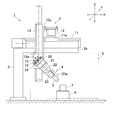
- the working device 1 includes a gantry 2, a linear motion unit 3 installed with the base fixed to the gantry 2, and a base fixed to an output portion of the linear motion unit 3.
- the end effector 5 mounted on the output unit of the rotation unit 4.
- the end effector 5 performs an operation on the workpiece 7 placed on the workpiece placement table 6.
- the end effector 5 may perform work while contacting the workpiece 7 or may perform work while being contacted.
- the work on the workpiece 7 by the end effector 5 is possible within the range of the work space S below the horizontal portion 2a of the gantry 2.
- the linear motion unit 3 has a configuration of three degrees of freedom by combining three linear motion actuators.
- the rotation unit 4 has a configuration with three degrees of freedom by combining a plurality of rotation mechanisms having one degree of freedom or more. Therefore, this working device 1 has a configuration with 6 degrees of freedom as a whole.
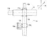
- FIG. 2A and 2B are a front view and a plan view of the linear motion unit 3.
- FIG. The linear motion unit 3 includes a first linear motion actuator 11, a second linear motion actuator 12, and a third linear motion actuator 13.
- the first linear actuator 11 is installed on the horizontal portion 2a of the gantry 2 and has a stage 11a that moves forward and backward in the left-right direction (X-axis direction).
- the second linear actuator 12 is provided on the stage 11a of the first linear actuator 11, and has a stage 12a that advances and retreats in the front-rear direction (Y-axis direction).
- the third linear actuator 13 is provided on the stage 12a of the second linear actuator 12, and has a stage 13a that advances and retreats in the vertical direction (Z-axis direction).
- the first to third linear actuators 11, 12, and 13 are electric actuators having motors 11b, 12b, and 13b as drive sources, respectively.
- the first to third linear motion actuators 11, 12, and 13 are arranged such that the respective stages 11a, 12a, and 13a face outward with respect to the work space S (FIG. 1).
- the fixed portion of the first linear motion actuator 11 that does not move back and forth constitutes the base of the linear motion unit 3 that is fixed to the gantry 2.
- the stage 13a of the third linear actuator 13 constitutes an output unit of the linear unit 3 to which the base of the rotary unit 4 is fixed.
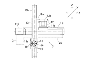
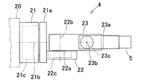
- the rotation unit 4 includes a rotation unit attachment member 20 fixed to the output portion of the linear motion unit 3 (FIG. 1), a first rotation mechanism 21 attached to the rotation unit attachment member 20, and the first rotation.
- a second rotating mechanism 22 attached to the rotating portion 21a of the mechanism 21 and a third rotating mechanism 23 attached to the rotating portion 22a of the second rotating mechanism 22 are provided.
- the rotation axes 21b, 22b, and 23b of the first to third rotation mechanisms 21, 22, and 23 are orthogonal to each other.
- the rotation drive sources of these rotation mechanisms 21, 22, and 23 are, for example, motors 21c, 22c, and 23c.
- the rotating unit mounting member 20 constitutes the base of the rotating unit 4 that is fixed to the output unit of the linear motion unit 3. Further, the rotating portion 23a of the third rotating mechanism 23 constitutes an output portion of the rotating unit 4 to which the end effector 5 is attached.
- a positioning hole 16 is provided. Only one first screw hole 14 is provided at the center of the portion of the stage 13a where the rotary unit mounting member 20 is fixed.
- a plurality (eight in this embodiment) of second screw holes 15 are provided on the circumference centered on the first screw hole 14 in the stage 13a.
- the positioning hole 16 is on the circumference centered on the first screw hole 14 in the stage 13a and on the circumference having a smaller radius than the circumference on which the second screw hole 15 is provided. The same number as 15 is provided.
- the rotary unit mounting member 20 has three bolt insertion holes (not shown) arranged in a straight line corresponding to the first screw holes 14 and the two second screw holes 15 and two positioning holes inserted into the positioning holes 16. A projection (not shown) is provided.
- the fixing of the rotary unit mounting member 20 to the stage 13a that is the output portion of the third linear actuator 13 is performed according to the following procedure. First, the two positioning protrusions of the rotary unit mounting member 20 are engaged with the two positioning holes 16 of the stage 13a. Thereby, the angle of the front view of the rotary unit attachment member 20 with respect to the stage 13a is determined.
- the mounting bolts 24 are inserted into the three bolt insertion holes of the rotary unit mounting member 20, and the mounting bolts 24 are inserted into the first screw holes 14 and the two second screw holes of the stage 13a. 15 is screwed. Thereby, the rotation unit attachment member 20 is fixed to the stage 13a.
- the positioning hole 16 of the stage 13a with which the positioning projection of the rotary unit mounting member 20 is engaged the mounting angle of the base portion of the rotary unit 4 with respect to the output portion of the linear motion unit 3 can be changed.
- the position of the end effector 5 is mainly determined by the linear motion unit 3 having three degrees of freedom, and the posture of the end effector 5 is determined by the rotation unit 4 having three degrees of freedom.
- the first to third linear actuators 11, 12, 13 of the linear motion unit 3 and the first to third rotational mechanisms 21, 22, 23 of the rotational unit 4 include the end effector 5 expressed in an orthogonal coordinate system. Corresponds to position and posture. Therefore, it is easy to imagine the operations of the first to third linear motion actuators 11, 12, 13 and the first to third rotating mechanisms 11, 12, 13 with respect to the position and posture of the end effector 5, and the posture teaching work or the like can be performed. The operation pattern can be easily set.
- the operating positions of the first to third linear actuators 11, 12, and 13 and the operating angles of the first to third rotating mechanisms 21, 22, and 23 are uniquely determined. Determined. That is, it has no singularity. For these reasons, it is easy to imagine in which direction the tip moves when each axis is moved during teaching. Therefore, the operation apparatus 1 can be operated without skilled knowledge and experience.
- the end effector 5 Since the position of the end effector 5 is determined by the first to third linear actuators 11, 12, and 13, the end effector 5 can be linearly moved at high speed and accurately. In addition, since the first to third linear actuators 11, 12, and 13 are used in the parts that greatly affect the movable range, it is easy to use mechanical stoppers, limit sensors, etc. according to the work contents and surrounding environment. The operating range can be limited.
- the work space S can be widened.
- the linear motion unit 3 and the rotary unit 4 are provided separately, only one of the units can be changed when the specifications of the work device 1 are changed.
- the rotation unit 4 can be changed from the form shown in FIG. 3 to the form shown in FIG. 5 described later, the form shown in FIG. 12, the form shown in FIG. As a result, it is possible to share parts among the work apparatuses 1 having different specifications.
- the rotating unit mounting member 20, which is the base of the rotating unit 4 is attached to the stage 13 a of the third linear actuator 13 that is the output unit of the linear moving unit 3 by using the mounting bolt 24 so that the mounting angle can be changed. It has been. For this reason, the apparatus configuration can be easily changed according to the work content and the surrounding environment.
- the work apparatus 1 can coexist with a person because the operation amount of the entire apparatus when performing a fine work is small. That is, work close to manual work performed by a person can be automatically performed.
- the setup change time and adjustment time can be shortened, and high-speed operation can be achieved, so that productivity can be improved.
- the enclosure can be a simple shape such as a rectangular parallelepiped. In that case, the volume of the internal space of the enclosure is substantially equal to the volume of the region in which the movable part of the apparatus moves. For this reason, a compact configuration can be realized even if the enclosure is included.
- the working device 1 includes a first rotating mechanism 21 in which the rotating unit 4 is a rotating mechanism having one degree of freedom, and a second rotating mechanism including a link actuator 29 having two degrees of freedom. It consists of That is, the second rotation mechanism 22 and the third rotation mechanism 23 in the first embodiment of FIG.
- the first rotation mechanism 21 constitutes “another rotation mechanism other than the link actuator 29”.
- Other structures are the same as those of the first embodiment shown in FIG.
- the link actuating device 29 has a parallel link mechanism 30 and an attitude control actuator 31 for actuating the parallel link mechanism 30.
- 6 and 7 are perspective views of the parallel link mechanism 30 and show different states from each other.
- the parallel link mechanism 30 includes a link hub 32 on the proximal end side, a link hub 33 on the distal end side, and a link hub 33 on the distal end side with respect to the link hub 32 on the proximal end side.
- three sets of link mechanisms 34 that connect the two in a posture-changeable manner. In FIG. 5, only one set of link mechanisms 34 is shown. The number of link mechanisms 34 may be four or more.
- Each link mechanism 34 is a four-joint chain link mechanism including four rotation pairs having a proximal end link member 35, a distal end link member 36, and a central link member 37.
- the end link members 35 and 36 on the proximal end side and the distal end side are L-shaped.
- One end of the end link member 35 on the base end side is rotatably connected to the link hub 32 on the base end side, and one end of the end link member 36 on the front end side is rotatably connected to the link hub 33 on the front end side.
- the central link member 37 has both ends connected to the other ends of the end link members 35 and 36 on the proximal end side and the distal end side in a freely rotatable manner.
- the parallel link mechanism 30 has a structure in which two spherical link mechanisms are combined.
- the parallel link mechanism 30 includes a rotation pair of a base end side link hub 32 and a base end side end link member 35, and a base end side end link member 35.
- the central axis of the rotation pair of the central link member 37 intersect at the spherical link center PA (FIG. 5) on the base end side.
- the central axis of the rotational pair of the distal end side link hub 33 and the distal end side end link member 36 and the rotational end pair of the distal end side end link member 36 and the central link member 37 is the spherical link center PB on the distal end side. (Fig. 5).
- the distance from the rotation pair of the base end side link hub 32 and the base end side end link member 35 to the base end side spherical link center PA is the same, and the base end side end link member 35 and The distance from each rotation pair of the central link member 37 to the spherical link center PA on the base end side is also the same.
- the distance from each rotation pair of the link hub 33 on the distal end side and the end link member 36 on the distal end side to the spherical link center PB on the distal end side is also the same, and the end link member 36 on the distal end side and the central link member on the distal end side are the same.
- the distance from each rotation pair 37 to the spherical link center PB on the tip side is the same.
- the central axis of each rotational pair of the proximal and distal end link members 35 and 36 and the central link member 37 may have a certain crossing angle ⁇ (FIG. 5) or may be parallel. Good.
- FIG. 8 is a cross-sectional view taken along the line VIII-VIII in FIG.
- the center axis O1 of each rotation pair of the link hub 32 on the base end side and the end link member 35 on the base end side, and each rotation pair of the center link member 37 and the end link member 35 on the base end side are shown.
- the relationship between the central axis O2 and the spherical link center PA on the base end side is shown. That is, the point where the central axis O1 and the central axis O2 intersect is the spherical link center PA on the base end side.
- the shape and positional relationship of the distal end side link hub 33 and the distal end side end link member 36 are also the same as in FIG. 8 (not shown).
- the angle ⁇ formed with the axis O2 is 90 °. However, the angle ⁇ may be other than 90 °.
- the three sets of link mechanisms 34 have the same geometric shape.
- the geometrically identical shape is expressed by a geometric model in which each link member 35, 36, and 37 is expressed by a straight line, that is, each rotation pair and a straight line connecting these rotation pairs.
- a model says that the base end side part and front end side part with respect to the center part of the center link member 37 are symmetrical shapes.
- FIG. 9 is a diagram in which a set of link mechanisms 34 is expressed by a straight line.
- the parallel link mechanism 30 of this embodiment is a rotationally symmetric type, and includes a proximal end side link hub 32 and a proximal end side end link member 35, a distal end side link hub 33 and a distal end side end link member 36.
- the positional relationship is a positional relationship that is rotationally symmetric with respect to the center line C of the central link member 37.
- the central part of the central link member 37 is located on a common track circle.
- the link hub 32 on the proximal end side, the link hub 33 on the distal end side, and the three sets of link mechanisms 34 allow the link hub 33 on the distal end side to rotate about two orthogonal axes with respect to the link hub 32 on the proximal end side.
- the degree mechanism is configured.
- the position of the link hub 33 on the distal end side with respect to the link hub 32 on the proximal end side is a mechanism whose posture can be freely changed with two degrees of freedom.
- this two-degree-of-freedom mechanism is compact, the movable range of the link hub 33 on the distal end side with respect to the link hub 32 on the proximal end side can be widened.
- a straight line that passes through the spherical link centers PA and PB and intersects with the central axis O1 (FIG. 8) of each rotation pair of the link hubs 32 and 33 and the end link members 35 and 36 at right angles is the central axis of the link hubs 32 and 33.
- QA and QB the maximum value of the bending angle ⁇ (FIG. 9) between the center axis QA of the link hub 32 on the proximal end side and the center axis QB of the link hub 33 on the distal end side can be about ⁇ 90 °.
- the turning angle ⁇ (FIG.
- the bending angle ⁇ is a vertical angle at which the central axis QB of the distal link hub 33 is inclined with respect to the central axis QA of the proximal link hub 32.
- the turning angle ⁇ is a horizontal angle at which the central axis QB of the distal link hub 33 is inclined with respect to the central axis QA of the proximal link hub 32.
- the posture change of the distal end side link hub 33 with respect to the proximal end side link hub 32 is performed with an intersection O between the central axis QA of the proximal end side link hub 32 and the central axis QB of the distal end side link hub 33 as a rotation center.
- FIG. 6 shows a state where the central axis QA of the link hub 32 on the proximal end side and the central axis QB of the link hub 33 on the distal end side are on the same line.
- FIG. 7 shows a state in which the central axis QB of the distal end side link hub 33 takes a certain operating angle with respect to the central axis QA of the proximal end side link hub 32. Even if the posture changes, the distance L (FIG. 9) between the spherical link centers PA and PB on the proximal end side and the distal end side does not change.
- the parallel link mechanism 30 functions as a constant velocity universal joint that rotates at a constant speed with the same rotation angle on the proximal end side and the distal end side when transmitting rotation from the proximal end side to the distal end side.
- Condition 1 The angles and lengths of the central axes O1 of the rotational pairs of the link hubs 32 and 33 and the end link members 35 and 36 in each link mechanism 34 are equal to each other.
- Condition 2 The central axis O1 of the rotational pair of the link hubs 32, 33 and the end link members 35, 36 and the central axis O2 of the rotational pair of the end link members 35, 36 and the central link member 37 are proximal. And at the front end side, they intersect at the spherical link centers PA and PB.
- Condition 3 The geometric shapes of the proximal end side end link member 35 and the distal end side end link member 36 are equal.
- Condition 4 The geometric shapes of the proximal end portion and the distal end portion of the central link member 37 are equal.
- Condition 5 With respect to the symmetry plane of the central link member 37, the angular positional relationship between the central link member 37 and the end link members 35 and 36 is the same on the proximal end side and the distal end side.
- the link hub 32 on the base end side includes a base end member 40 and three rotating shaft connecting members 41 provided integrally with the base end member 40. .
- a circular through hole 40 is formed at the center of the base end member 40, and three rotary shaft connecting members 41 are arranged at equal intervals in the circumferential direction around the through hole 40a. Yes.
- the center of the through hole 40a is positioned on the central axis QA (FIG. 5) of the link hub 32 on the proximal end side.
- a rotating shaft 42 whose shaft center intersects the central axis QA of the link hub 32 on the proximal end side is rotatably connected to each rotating shaft connecting member 41.
- One end of an end link member 35 on the base end side is connected to the rotating shaft 42.
- the rotary shaft 42 is rotatably supported by the rotary shaft connecting member 41 via two bearings 43.
- the bearing 43 is a ball bearing such as a deep groove ball bearing or an angular ball bearing.
- the bearing 43 is installed in a fitted state in the hollow hole 44 of the cylindrical rotating shaft coupling member 41 and is fixed by a method such as press fitting, bonding, or caulking. The same applies to the types and installation methods of the bearings provided in other rotating pairs.
- the rotating shaft 42 is coupled to one end of the end link member 35 on the base end side and a fan-shaped bevel gear 45 described later, and both rotate integrally with the rotating shaft 42.
- a notch 46 is formed at one end of the base end side end link member 35, and the rotation shaft connecting member is provided between the inner and outer rotation shaft support portions 47 and 48, which are both sides of the notch 46. 41 is arranged.
- the bevel gear 45 is disposed in contact with the inner surface of the inner rotary shaft support 47.
- the rotating shaft 55 is coupled to the other end of the end link member 35 on the base end side.
- the rotating shaft 55 is rotatably connected to one end of the central link member 37 via two bearings 53.
- a notch 56 is formed at the other end of the base end side end link member 35, and a central link member is provided between the inner and outer rotary shaft support portions 57 and 58 that are both side portions of the notch 56.
- One end of 37 is arranged.
- the rotation shaft 55 is inserted from the outside in the order of a through hole formed in the outer rotation shaft support portion 58, an inner ring of the bearing 53, and a through hole formed in the inner rotation shaft support portion 57. Thereafter, the inner and outer rotary shaft support portions 57 and 58 and the inner ring of the bearing 53 are sandwiched and coupled by the nut 60 screwed to the head portion 55a of the rotary shaft 55 and the screw portion 55b of the rotary shaft 55. Spacers 61 and 62 are interposed between the inner and outer rotary shaft support portions 57 and 58 and the bearing 53, and a preload is applied to the bearing 53 when the nut 60 is screwed.
- the link hub 33 on the distal end side has a distal end member 70 and three rotary shaft coupling members 71 provided on the inner surface of the distal end member 70 at equal intervals in the circumferential direction. is doing.
- the center of the circumference where the rotation shaft connecting member 71 is arranged is located on the center axis QB of the link hub 33 on the distal end side.
- Each rotary shaft connecting member 71 is rotatably connected to a rotary shaft 73 whose axis intersects the link hub central axis QB.
- One end of an end link member 36 on the distal end side is connected to the rotation shaft 73 of the link hub 33 on the distal end side.
- a rotating shaft 75 that is rotatably connected to the other end of the center link member 37 is connected to the other end of the end link member 36 on the front end side.
- the rotation shaft 73 of the link hub 33 on the distal end side and the rotation shaft 75 of the central link member 37 are similar to the above-described rotation shafts 42 and 55, and the rotation shaft connecting member 71 and the rotation shaft connection member 71 via two bearings (not shown).
- the other end of the central link member 37 is rotatably connected.
- the parallel link mechanism 30 is installed in the first rotation mechanism 21 by connecting the base end member 40 to the base member 80 via a plurality of shafts 81.
- the central axis QA of the link hub 32 on the proximal end side and the rotation axis 21b of the first rotation mechanism 21 are located on the same line.
- the base member 80 is fixed to the rotating portion 21 a of the first rotating mechanism 21.
- a cover 82 is attached between the outer peripheral edge of the base end member 40 and the outer peripheral edge of the base member 80. Between the base end member 40 and the base member 80 is a shielding space 83 shielded from the outside by the cover 82.
- the attitude control actuator 31 that operates the parallel link mechanism 30 is disposed in the shielding space 83 and attached to the proximal end member 40.
- the number of attitude control actuators 31 is three, which is the same as the number of link mechanisms 34.
- the attitude control actuator 31 is, for example, a rotary actuator such as a motor.
- the bevel gear 76 attached to the rotation output shaft 31a of the attitude control actuator 31 and the fan-shaped bevel gear 45 attached to the rotation shaft 42 of the link hub 32 on the proximal end side are meshed with each other. That is, the bevel gear 76 and the fan-shaped bevel gear 45 constitute an axis orthogonal reduction gear 77.
- An axis orthogonal reduction device may be configured using a mechanism (for example, a worm mechanism) other than a bevel gear.
- the same number of posture control actuators 31 as the link mechanisms 34 are provided, but at least two of the three sets of link mechanisms 34 may be provided with the posture control actuators 31. Accordingly, the posture of the link hub 33 on the distal end side with respect to the link hub 32 on the proximal end side can be determined.
- the link actuating device 29 actuates the parallel link mechanism 30 by rotationally driving each attitude control actuator 31. More specifically, when the attitude control actuator 31 is driven to rotate, the rotation is decelerated via the axis orthogonal type reduction gear 77 and transmitted to the rotary shaft 42, and the proximal end portion with respect to the proximal link hub 32. The angle of the link member 35 changes. As a result, the position and posture of the distal end side link hub 33 relative to the proximal end side link hub 32 are determined. Since the central axis QA of the link hub 32 on the base end side and the rotation axis 21b of the first rotation mechanism 21 are located on the same line, coordinate calculation is easy.
- the operator can easily imagine the operation of the work device 1 and thus can be operated easily. It can.
- the position of 3 degrees of freedom determined by the linear motion unit 3 is fixed, and the angle of 2 degrees of freedom among the angles of 3 degrees of freedom determined by the rotation unit 4 is fixed, and the remaining one degree of freedom angle
- the work can be performed while changing the posture of the end effect 5 by changing only the angle (for example, the angle around the central axis QB of the link hub 33 on the distal end side).
- the link actuating device 29 has a wide movable range and can operate smoothly. Therefore, when the link actuating device 29 is included in the rotary unit 4, high-speed and fine work can be performed. Moreover, since the link actuating device 29 has a wide movable range while having a compact configuration, the entire work device 1 has a compact configuration.
- the link actuator 29 can reduce the load. For this reason, the link actuator 29 can be made compact and lightweight.
- the parallel link mechanism 30 of the link operating device 29 has a constant velocity universal joint configuration. Therefore, the cooperative operation of the link actuating device 29 and the first rotating mechanism 21 facilitates the work performed while changing the posture of the end effect 5 only by the angle around the central axis QB of the link hub 33 on the distal end side.
- the rotation angle is limited.
- FIG. 10 shows a rotating unit 4 in which the arrangement of the first rotating mechanism 21 and the link actuating device 29 is reversed from that of the second embodiment of FIG.
- the center axis QB of the link hub 33 on the distal end side of the link actuating device 29 and the rotation axis 21b of the first rotation mechanism 21 are located on the same line.
- Other configurations are the same as those of the second embodiment of FIG.
- the cable connected to the attitude control actuator 31 can be easily wired, and the rotation angle is hardly limited.
- the load of the link actuator 29 increases.
- this working apparatus 1 also includes a first rotating mechanism 21 that is a rotating mechanism with one degree of freedom and a rotating mechanism with two degrees of freedom. And a link actuating device 29 which is a mechanism.
- the work device 1 of the fourth embodiment is different from the second embodiment of FIG. 4 in that the first rotation mechanism 21 is arranged at the center of each posture control actuator 31 of the link actuator 29. It is.
- the first rotating mechanism 21 has a fixed portion 90 fixed to the base member 80, a rotating portion 91 fixed to the proximal end member 40 of the link actuator 29, and the fixed portion 90.
- Two bearings 92 that rotatably support the rotating portion 91, a motor 93 that is a drive source installed in the fixed portion 90, and a pair of spur gears 94 and 95 that transmit the rotation of the motor 93 to the rotating portion 91. And.
- the base member 80 is fixed to the rotating unit mounting member 20.
- the fixed portion 90 includes a first mounting member 96 having a horseshoe-shaped cross section fixed to the base member 80 and a second mounting member 97 fixed to the first mounting member 96 with a bottom portion 97a.
- the second attachment member 97 has a cylindrical portion 97b extending upward from the outer peripheral edge of the bottom portion 97a in FIG.
- the rotating portion 91 is fixed to the proximal end member 40 of the proximal end side link hub 32 so that the rotational axis 91a thereof is positioned coaxially with the central axis QA of the proximal end side link hub 32.
- the two bearings 92 are disposed on the inner periphery of the cylindrical portion 97 b of the second mounting member 97.
- the motor 93 is disposed in the recess 96 a of the first mounting member 96 having a horseshoe cross section, and is fixed to the bottom 97 a of the second mounting member 97.
- the output shaft 93a of the motor 93 extends upward through the bottom portion 97a of the second mounting member 97, and a drive-side spur gear 94 is attached to the upper end thereof.
- the drive-side spur gear 94 meshes with a driven-side spur gear 95 attached to the rotating portion 91.
- the driven side spur gear 95 is fitted to the outer periphery of the rotating portion 91.
- a screw portion is provided at the lower end of the rotating portion 91, and a spur gear 95 is fastened and fixed to the rotating portion 91 by a nut 98 screwed into the screw portion.
- the three attitude control actuators 31 of the link actuating device 29 are arranged on a virtual circumference in the base end member 40, and the rotation output shaft 31 a of each attitude control actuator 31.
- the rotational driving force is transmitted to the link mechanism 34 through the axis-reduced speed reducer 77.
- the first rotation mechanism 21 can be arranged at the center of the arrangement of the attitude control actuators 31 as in the fourth embodiment. Thereby, the rotation unit 4 becomes a compact structure.
- the internal space of the link actuating device 29 refers to a space surrounded by the link hub 32 on the proximal end side, the link hub 33 on the distal end side, and each link mechanism 34.
- FIG. 14 is a front view of the main part of the rotating unit of the working device according to the fifth embodiment of the present invention.
- the first rotation mechanism 21 is arranged at the center of each attitude control actuator 31 of the link actuator 29. This point is the same as that of the fourth embodiment shown in FIG. 12, but is different from the fourth embodiment shown in FIG. 12 in that the drive source of the first rotating mechanism 21 is the hollow shaft motor 110.
- the hollow shaft motor 110 has a motor body 110 a fixed to a base member 80 via a motor mounting member 111.
- the base end member 40 of the base end side link hub 32 is fixed to the output shaft 110 b of the hollow shaft motor 110.
- the hollow shaft motor 110 has a wiring hole 112 that passes through the motor body 110a and the output shaft 110b in the axial direction.
- the base end member 40 of the link hub 32 on the base end side is provided with a wiring hole 113 coaxially with the wiring hole 112.
- Other configurations are the same as those of the fourth embodiment shown in FIG. 12, and the same operations and effects as those of the fourth embodiment can be obtained.
- FIG. 15 to 17 show a schematic configuration of a double-armed working device according to a sixth embodiment of the present invention.
- two working devices 1 of the fourth embodiment shown in FIG. 11 are arranged side by side so as to be geometrically symmetrical. Has been placed.
- the platforms 2 and 2 of each work device 1 are connected to each other at the ends of the horizontal portions 2a and 2a, and are a gate-shaped platform 2A as a whole.
- the sixth embodiment uses the work device 1 of the fourth embodiment shown in FIG. 11, the work device of another embodiment may be used.
- the work 7 to be worked can pass under the work devices 1 and 1.
- the work mounting table 6 can be a conveyor device that can transport the work 7 in a direction orthogonal to the paper surface in FIG. 15, and the working devices 1 and 1 can be installed on the conveyor line.
- the movable range in the width direction of the work devices 1 and 1 can be limited within the width direction of the gantry 2A, the occupation area of the work devices 1 and 1 can be small.
- the movable range of the work devices 1 and 1 is limited, the worker can work with peace of mind even if the worker is next to the work devices 1 and 1.
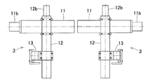
- FIG. 17 is a plan view of the linear motion units 3 and 3 of the double-arm type work apparatus 120 shown in FIGS. 15 and 16. These linear motion units 3 and 3 are the same as the linear motion unit 3 of each work apparatus 1 shown in FIGS. 1, 4 and 11, and each of the first linear motion actuator 11 and the second linear motion actuator 12. Motors 11 b and 12 b are disposed on the central axes of the linear actuators 11 and 12.
- FIG. 18 is a plan view showing another embodiment of the linear motion units 3 and 3.
- the motors 11b and 12b of the first linear motion actuator 11 and the second linear motion actuator 12 are arranged offset from the central axes of the linear motion actuators 11 and 12.
- the rotations of the motors 11b and 12b are transmitted to the drive portions of the linear motion actuators 11 and 12 through power transmission means 121 such as a chain.
- the linear motion unit 3 can be changed to the sixth embodiment shown in FIG. 17 or the seventh embodiment shown in FIG. Since the linear motion unit 3 and the rotation unit 4 are provided separately, such a change is easy.
- Base end side end link member 36 ... Tip side end link member 37 ... center link member 100, 101, 102, 112, 113 ... wiring hole 120 ... double-arm type work device O1 ... center axis O2 of the rotation pair of link hub and end link member ... end link member and center link member Center axis PA, PB of rotating pair ... Spherical link center QA, QB ... Center axis S of link hub S ... Work space
Abstract
作業装置(1)は、エンドエフェクタ(5)を用いて作業を行う6自由度の構成であって、3つの直動アクチュエータ(11,12,13)を組み合わせた3自由度の直動ユニット(3)と、1自由度以上の回転自由度を持つ複数の回転機構(21,22,23)を組み合わせた3自由度の回転ユニット(4)とを備える。直動ユニット(3)の基部が、架台(2)に固定されている。回転ユニット(4)の基部が、直動ユニット(3)の出力部(13a)に固定されている。回転ユニット(4)の出力部(23a)にエンドエフェクタ(5)が搭載されている。
Description
この出願は、2016年4月20日出願の特願2016-084171の優先権を主張するものであり、その全体を参照により本願の一部をなすものとして引用する。
この発明は、医療機器や産業機器等の高速、高精度の作業を必要とする機器、組立てのようなきめ細かい作業を必要とする機器、人と共存するロボット等に用いられる作動装置および双腕型作動装置に関する。
特許文献1、2に、6自由度の多関節ロボット型の作業装置が提案されている。特許文献1は単腕型の構成であり、特許文献2は双腕型の構成である。これらの作業装置は、回転1自由度の機構を6つ組み合わせることで、全体で6自由度の構成としている。
特許文献1の作業装置は、すべて回転1自由度の機構の組合せで構成されているので、以下の課題1~6がある。
(課題1)先端に搭載するエンドエフェクタの姿勢を少し変更する場合や直線移動する場合、複数のモータを協調させて駆動する必要があり、きめ細かい作業を高速に行うことができない。
(課題1)先端に搭載するエンドエフェクタの姿勢を少し変更する場合や直線移動する場合、複数のモータを協調させて駆動する必要があり、きめ細かい作業を高速に行うことができない。
(課題2)エンドエフェクタの姿勢を少し変更するだけの場合でも、手首関節(エンドエフェクタに近い関節)だけでなく腕(エンドエフェクタから離れた部位)の移動量が大きくなってしまうので、作業装置の一部が周囲のものと接触し易い。接触を完全に避けるためには、大きな囲いを設ける必要があり、専有面積が広くなる。
(課題3)エンドエフェクタの1つの姿勢に対して複数の解が存在する場合があり、教示を行う際に各軸を動かしても先端がどのような方向に移動するかイメージし難い。このため、操作を行うには知識や経験が必要である。
(課題3)エンドエフェクタの1つの姿勢に対して複数の解が存在する場合があり、教示を行う際に各軸を動かしても先端がどのような方向に移動するかイメージし難い。このため、操作を行うには知識や経験が必要である。
(課題4)可動範囲が広いので、人や物との接触を想定して安全機能を充実させる必要があり、装置全体が高価になる。
(課題5)人や物との接触を避けるために、動作速度を落として作業を行ったり、動作範囲で能力以下に抑えて作業を行ったりする必要があり、能力を十分に発揮できない。
(課題6)安全機能が充実されていても、作業者は作業装置と接触することに対して抵抗があり、人と作業装置が共存することが難しい。
(課題5)人や物との接触を避けるために、動作速度を落として作業を行ったり、動作範囲で能力以下に抑えて作業を行ったりする必要があり、能力を十分に発揮できない。
(課題6)安全機能が充実されていても、作業者は作業装置と接触することに対して抵抗があり、人と作業装置が共存することが難しい。
特許文献2の作業装置も、特許文献1の作業装置と同様の課題がある。加えて、双腕型である特許文献2の作業装置には、以下の課題7,8がある。
(課題7)各アームの可動範囲が広いので、アーム同士が干渉する領域も広い。アーム同士が接触しないように動作を行うには知識や経験が必要である。
(課題8)可動範囲が広いアームを2つ有するので、囲いを設ける場合にはさらに専有面積が広くなる。
(課題7)各アームの可動範囲が広いので、アーム同士が干渉する領域も広い。アーム同士が接触しないように動作を行うには知識や経験が必要である。
(課題8)可動範囲が広いアームを2つ有するので、囲いを設ける場合にはさらに専有面積が広くなる。
この発明の目的は、細かい作業を行うときの装置全体の動作量が小さくて済み、人と共存することができ、人が行う手作業に近い作業を自動で行うことができる作業装置を提供することである。
この発明の作業装置は、エンドエフェクタを用いて作業を行う6自由度の作業装置であって、3つの直動アクチュエータを組み合わせた3自由度の直動ユニットと、1自由度以上の回転自由度を持つ複数の回転機構を組み合わせた3自由度の回転ユニットとを備えている。前記直動ユニットの基部は、作業装置の架台に固定して設置されている。前記回転ユニットの基部が前記直動ユニットの出力部に固定され、かつ前記回転ユニットの出力部に前記エンドエフェクタが搭載されている。
この構成によると、主に3自由度の直動ユニットによってエンドエフェクタの位置が決められ、かつ3自由度の回転ユニットによってエンドエフェクタの姿勢が決められる。直動ユニットの各直動アクチュエータおよび回転ユニットの各回転機構が、直交座標系で表現されるエンドエフェクタの位置、姿勢に対応する。これにより、エンドエフェクタの位置、姿勢に対する各直動アクチュエータおよび各回転機構の動作をイメージし易く、姿勢教示作業等の動作パターンの設定が容易である。また、エンドエフェクタの位置、姿勢に対して、各直動アクチュエータの動作位置および各回転機構の動作角度が一意に決まる。つまり、特異点を持たない。これらのことから、熟練した知識や経験が無くても、作業装置の操作を行うことができる。
他に、以下の作用・効果(効果1~5)が得られる。
(効果1)組立て作業のようなきめ細かい作業を行う場合、主に回転ユニットだけを動かして作業を行うことができる。そのため、直動ユニットの動作量が小さくて済み、装置全体の可動範囲を小さくできる。また、囲いを設ける必要のある面積を狭くできる。
(効果2)可動範囲に大きく影響する部分に直動アクチュエータを使用しているので、作業内容や周囲の環境に応じて、メカストッパやリミットセンサを用いて容易に動作範囲を制限できる。
(効果1)組立て作業のようなきめ細かい作業を行う場合、主に回転ユニットだけを動かして作業を行うことができる。そのため、直動ユニットの動作量が小さくて済み、装置全体の可動範囲を小さくできる。また、囲いを設ける必要のある面積を狭くできる。
(効果2)可動範囲に大きく影響する部分に直動アクチュエータを使用しているので、作業内容や周囲の環境に応じて、メカストッパやリミットセンサを用いて容易に動作範囲を制限できる。
(効果3)直動ユニットと回転ユニットを別々に設けているので、作業装置を仕様変更する場合にどちらかのユニットのみを変更することが可能である。これにより、仕様が異なる作業装置間での部品の共通化を図れる。
(効果4)直動アクチュエータによってエンドエフェクタの位置を決めるので、エンドエフェクタの直線動作を高速かつ正確に行うことができる。
(効果5)直方体等の簡単な形状でカバー等の囲いを設置することができる。その場合、囲いの内部空間体積と装置の可動部が移動する領域の体積とがほぼ等しい。このため、囲いを含めてもコンパクトな構成を実現できる。
(効果4)直動アクチュエータによってエンドエフェクタの位置を決めるので、エンドエフェクタの直線動作を高速かつ正確に行うことができる。
(効果5)直方体等の簡単な形状でカバー等の囲いを設置することができる。その場合、囲いの内部空間体積と装置の可動部が移動する領域の体積とがほぼ等しい。このため、囲いを含めてもコンパクトな構成を実現できる。
この発明において、前記直動ユニットの前記各直動アクチュエータは、それぞれの進退部分からなるステージが、前記エンドエフェクタによって作業が行われる作業空間に対して外側を向くように配置されているとよい。各直動アクチュエータのステージを作業空間に対して外側を向くように配置することで、作業空間を広くすることができる。
この発明において、前記回転ユニットは前記複数の回転機構のうちの少なくとも1つが2自由度のリンク作動装置であってもよい。このリンク作動装置は、基端側のリンクハブに対し先端側のリンクハブが3組以上のリンク機構を介して姿勢を変更可能に連結され、前記各リンク機構は、前記基端側のリンクハブおよび前記先端側のリンクハブに一端が回転可能に連結された基端側および先端側の端部リンク部材と、これら基端側および先端側の端部リンク部材の他端に両端がそれぞれ回転可能に連結された中央リンク部材とを有し、前記3組以上のリンク機構のうちの2組以上のリンク機構に前記基端側のリンクハブに対する前記先端側のリンクハブの姿勢を任意に変更させる姿勢制御用アクチュエータが設けられた構成とするとよい。
リンク作動装置は、基端側のリンクハブと、先端側のリンクハブと、3組以上のリンク機構とで、基端側のリンクハブに対し先端側のリンクハブが直交2軸周りに回転自在な2自由度機構を構成する。この2自由度機構は、コンパクトでありながら、先端側のリンクハブの可動範囲を広くとれる。例えば、基端側のリンクハブの中心軸と先端側のリンクハブの中心軸の折れ角の最大値は約±90°であり、基端側のリンクハブに対する先端側のリンクハブの旋回角を0°~360°の範囲に設定できる。また、折れ角90°、旋回角360°の作動範囲において特異点を持たないスムーズな動作が可能である。
上記のように、可動範囲が広くスムーズな動作が可能なリンク作動装置を使用することで、高速できめ細かい作業を行うことができる。また、リンク作動装置はコンパクトな構成でありながら可動範囲が広いので、作業装置全体がコンパクトな構成になる。
回転ユニットにリンク作動装置が含まれている場合、前記基端側のリンクハブの中心軸または前記先端側のリンクハブの中心軸と、前記リンク作動装置以外の他の回転機構の回転軸心とが同一線上に位置しているとよい。
ここで、基端側のリンクハブの中心軸は、前記基端側のリンクハブと前記基端側の端部リンク部材の各回転対偶の中心軸、および前記基端側の端部リンク部材と前記中央リンク部材の各回転対偶の中心軸がそれぞれ交差する点を基端側の球面リンク中心と称する場合に、この基端側の球面リンク中心を通り前記基端側のリンクハブと前記基端側の端部リンク部材の各回転対偶の中心軸と直角に交わる直線のことである。また、先端側のリンクハブの中心軸は、前記先端側のリンクハブと前記先端側の端部リンク部材の各回転対偶の中心軸、および前記先端側の端部リンク部材と前記中央リンク部材の各回転対偶の中心軸がそれぞれ交差する点を先端側の球面リンク中心と称する場合に、この先端側の球面リンク中心を通り前記先端側のリンクハブと前記先端側の端部リンク部材の各回転対偶の中心軸と直角に交わる直線のことである。
リンクハブの中心軸と他の回転機構の回転軸心とを同一線上に位置させると、座標計算が容易となる。また、作業者が作業装置の動作をイメージし易いので、簡単に操作できるようになる。例えば、直動ユニットで決定される3自由度の位置を固定し、かつ回転ユニットで決定される3自由度の角度のうち2自由度の角度を固定し、残りの1自由度の角度(例えば、先端側のリンクハブの中心軸周りの角度)だけを変更してエンドエフェクトの姿勢を変えながら作業を行うことができる。
上記構成において、前記リンク作動装置の前記基端側のリンクハブに前記他の回転機構の回転部分が直接または間接に結合され、前記リンク作動装置の前記先端側のリンクハブに前記エンドエフェクタが搭載されていてもよい。
このように、リンク作動装置の基端側に他の回転機構を配置し、かつ先端側にエンドエフェクタを配置した場合、リンク作動装置の姿勢制御用アクチュエータ用のケーブルについて考慮する必要があるので、回転角は制限されるが、リンク作動装置の負荷を軽減できるので、リンク作動装置のコンパクト化、軽量化を実現できる。
このように、リンク作動装置の基端側に他の回転機構を配置し、かつ先端側にエンドエフェクタを配置した場合、リンク作動装置の姿勢制御用アクチュエータ用のケーブルについて考慮する必要があるので、回転角は制限されるが、リンク作動装置の負荷を軽減できるので、リンク作動装置のコンパクト化、軽量化を実現できる。
リンク作動装置は、基端側から先端側へ回転伝達を行う場合に、基端側と先端側は同じ回転角になって等速で回転する等速自在継手の構成である。したがって、リンク作動装置と他の回転機構との協調制御により、エンドエフェクトの姿勢を先端側のリンクハブの中心軸周りの角度だけ変えながら行う作業が容易である。
上記構成において、前記リンク作動装置の前記2つ以上の姿勢制御用アクチュエータはロータリアクチュエータであって、その回転出力軸が前記基端側のリンクハブの中心軸と平行となるように配置され、前記回転出力軸の回転駆動力が軸直交型の減速機を介して前記リンク機構に伝達される構成であり、前記各姿勢制御用アクチュエータの並びの中心部に前記他の回転機構が配置されていてもよい。この場合、回転ユニットがコンパクトな構成になる。
上記構成において、前記他の回転機構は、少なくとも回転する部分に軸方向に貫通する配線用孔を有していてもよい。この場合、他の回転機構の配線用孔に配線を通すことにより、リンク機構と干渉させることなくリンク作動装置の内部空間側からエンドエフェクタに配線を繋げることができる。
この発明において、前記直動ユニットの前記出力部に対する前記回転ユニットの前記基部の取付角度が変更可能であってもよい。この場合、作業内容や周囲の環境に応じて装置構成を容易に変更することができる。
この発明の双腕型作業装置は、この発明の作業装置が、互いに幾何学的に対称となるように2つ並べて配置されている。作業装置を2つ並べた双腕型とすることで、人が両手で行うような作業が可能となる。これにより、人の代わりとなる作業、特に部品の組立てのような作業を行うことができる。
前記2つの作業装置が門形の架台に設置されていてもよい。この構成であると、作業装置の下を作業対象の部品を通過させることができる。例えば、コンベアライン上に作業装置を設置することができる。また、作業装置の幅方向の可動範囲を架台の幅方向内に制限することができるので、作業装置の占有面積が小さくて済む。さらに、作業装置の可動範囲が制限されるので、作業者が作業装置の横に居ても安心して作業することができる。
請求の範囲および/または明細書および/または図面に開示された少なくとも2つの構成のどのような組合せも、この発明に含まれる。特に、請求の範囲の各請求項の2つ以上のどのような組合せも、この発明に含まれる。
この発明は、添付の図面を参考にした以下の好適な実施形態の説明からより明瞭に理解されるであろう。しかしながら、実施形態および図面は単なる図示および説明のためのものであり、この発明の範囲を定めるために利用されるべきものではない。この発明の範囲は添付の請求の範囲によって定まる。添付図面において、複数の図面における同一の部品番号は、同一または相当部分を示す。
この発明の第1実施形態にかかる作業装置の概略構成を示す正面図である。
同作業装置の直動ユニットの正面図である。
同作業装置の直動ユニットの平面図である。
同作業装置の回転ユニットの正面図である。
同作業装置の回転ユニットの平面図である。
この発明の第2実施形態にかかる作業装置の概略構成を示す正面図である。
同作業装置の回転ユニットの一部を断面で表した正面図である。
同回転ユニットのリンク作動装置のパラレルリンク機構の斜視図である。
同パラレルリンク機構の異なる状態の斜視図である。
図5のVIII-VIII線に沿った断面図である。
同リンク作動装置の1つのリンク機構を直線で表現した図である。
この発明の第3実施形態にかかる作業装置の回転ユニットの正面図である。
この発明の第4実施形態にかかる作業装置の概略構成を示す図である。
同作業装置の回転ユニットの要部の正面図である。
図12のXIII-XIII線に沿った断面図である。
この発明の第5実施形態にかかる作業装置の回転ユニットの要部の正面図である。
この発明の第6にかかる双腕型作業装置の概略構成を示す図である。
同双腕型作業装置の斜視図である。
同双腕型作業装置の直動ユニットの平面図である。
この発明の第7実施形態にかかる双腕型作業装置の直動ユニットの平面図である。
以下、図面と共にこの発明の実施形態を説明する。
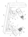
図1~図3は、この発明の第1実施形態に係る作業装置を示す。図1に概略構成を示すように、この作業装置1は、架台2と、この架台2に基部を固定して設置された直動ユニット3と、この直動ユニット3の出力部に基部を固定して設置された回転ユニット4と、この回転ユニット4の出力部に搭載されたエンドエフェクタ5とを備えている。エンドエフェクタ5は、ワーク載置台6の上に載置されたワーク7に対して作業を行う。エンドエフェクタ5は、ワーク7に対して接触して作業を行うものであってもよく、被接触で作業を行うものであってもよい。エンドエフェクタ5によるワーク7に対する作業は、架台2の水平部2aの下方の作業空間Sの範囲内で可能である。
図1~図3は、この発明の第1実施形態に係る作業装置を示す。図1に概略構成を示すように、この作業装置1は、架台2と、この架台2に基部を固定して設置された直動ユニット3と、この直動ユニット3の出力部に基部を固定して設置された回転ユニット4と、この回転ユニット4の出力部に搭載されたエンドエフェクタ5とを備えている。エンドエフェクタ5は、ワーク載置台6の上に載置されたワーク7に対して作業を行う。エンドエフェクタ5は、ワーク7に対して接触して作業を行うものであってもよく、被接触で作業を行うものであってもよい。エンドエフェクタ5によるワーク7に対する作業は、架台2の水平部2aの下方の作業空間Sの範囲内で可能である。
直動ユニット3は、3つの直動アクチュエータを組み合わせた3自由度の構成である。回転ユニット4は、1自由度以上の回転自由度を持つ複数の回転機構を組み合わせた3自由度の構成である。よって、この作業装置1は、全体で6自由度の構成である。
図2A,図2Bは直動ユニット3の正面図と平面図である。直動ユニット3は、第1の直動アクチュエータ11と、第2の直動アクチュエータ12と、第3の直動アクチュエータ13とを備える。第1の直動アクチュエータ11は、架台2の水平部2aに設置され、左右方向(X軸方向)に進退するステージ11aを有している。第2の直動アクチュエータ12は、第1の直動アクチュエータ11のステージ11aに設置され、前後方向(Y軸方向)に進退するステージ12aを有している。第3の直動アクチュエータ13は、第2の直動アクチュエータ12のステージ12aに設置され、上下方向(Z軸方向)に進退するステージ13aを有している。
第1~3の直動アクチュエータ11,12,13は、それぞれモータ11b,12b,13bを駆動源とする電動アクチュエータである。第1~3の直動アクチュエータ11,12,13は、それぞれのステージ11a,12a,13aが、作業空間S(図1)に対して外側を向くように配置されている。第1の直動アクチュエータ11における進退動作しない固定部分が、架台2に固定される直動ユニット3の基部を構成する。また、第3の直動アクチュエータ13のステージ13aが、回転ユニット4の基部が固定される直動ユニット3の出力部を構成する。
図3A,図3Bは回転ユニット4の正面図と平面図である。回転ユニット4は、直動ユニット3(図1)の出力部に固定された回転ユニット取付部材20と、この回転ユニット取付部材20に取り付けられた第1の回転機構21と、この第1の回転機構21の回転部分21aに取り付けられた第2の回転機構22と、この第2の回転機構22の回転部分22aに取り付けられた第3の回転機構23とを備える。第1~3の回転機構21,22,23の回転軸心21b,22b,23bは、互いに直交している。これら各回転機構21,22,23の回転駆動源は、例えばモータ21c,22c,23cである。
回転ユニット取付部材20が、直動ユニット3の出力部に固定される回転ユニット4の基部を構成する。また、第3の回転機構23の回転部分23aが、エンドエフェクタ5が取り付けられる回転ユニット4の出力部を構成する。
図2Aに示すように、直動ユニット3の出力部である第3の直動アクチュエータ13のステージ13aには、回転ユニット取付部材20を固定するための第1ねじ孔14、第2ねじ孔15および位置決め孔16が設けられている。第1ねじ孔14は、ステージ13aにおける回転ユニット取付部材20が固定される箇所の中心部に、1つだけ設けられている。第2ねじ孔15は、ステージ13aにおける第1ねじ孔14を中心とする円周上に複数(この実施形態では8個)設けられている。位置決め孔16は、ステージ13aにおける第1ねじ孔14を中心とする円周上であって、第2ねじ孔15が設けられている円周よりも半径が小さい円周上に、第2ねじ孔15と同数だけ設けられている。
回転ユニット取付部材20には、第1ねじ孔14と2つの第2ねじ孔15に対応する直線上に並ぶ3つのボルト挿通孔(図示せず)と、位置決め孔16に挿通される2つの位置決め用突起(図示せず)とが設けられている。
第3の直動アクチュエータ13の出力部であるステージ13aに対する、回転ユニット取付部材20の固定は、以下の手順で行われる。まず、回転ユニット取付部材20の2つの位置決め用突起を、ステージ13aの2つの位置決め孔16に係合させる。これにより、ステージ13aに対する回転ユニット取付部材20の正面視の角度が決まる。
この状態で、図1に示すように、回転ユニット取付部材20の3つのボルト挿通孔に取付ボルト24を挿通し、各取付ボルト24をステージ13aの第1ねじ孔14および2つの第2ねじ孔15に螺合させる。これにより、ステージ13aに回転ユニット取付部材20が固定される。回転ユニット取付部材20の位置決め用突起が係合されるステージ13aの位置決め孔16を変更することで、直動ユニット3の出力部に対する回転ユニット4の基部の取付角度が変更可能である。
この作業装置1の作用を説明する。
この構成によると、主に3自由度の直動ユニット3によってエンドエフェクタ5の位置が決められ、かつ3自由度の回転ユニット4によってエンドエフェクタ5の姿勢が決められる。直動ユニット3の第1~第3の直動アクチュエータ11,12,13および回転ユニット4の第1~第3の回転機構21,22,23が、直交座標系で表現されるエンドエフェクタ5の位置、姿勢に対応する。したがって、エンドエフェクタ5の位置、姿勢に対する第1~第3の直動アクチュエータ11,12,13および第1~第3の回転機構11,12,13の動作をイメージし易く、姿勢教示作業等の動作パターンの設定が容易である。
この構成によると、主に3自由度の直動ユニット3によってエンドエフェクタ5の位置が決められ、かつ3自由度の回転ユニット4によってエンドエフェクタ5の姿勢が決められる。直動ユニット3の第1~第3の直動アクチュエータ11,12,13および回転ユニット4の第1~第3の回転機構21,22,23が、直交座標系で表現されるエンドエフェクタ5の位置、姿勢に対応する。したがって、エンドエフェクタ5の位置、姿勢に対する第1~第3の直動アクチュエータ11,12,13および第1~第3の回転機構11,12,13の動作をイメージし易く、姿勢教示作業等の動作パターンの設定が容易である。
また、エンドエフェクタ5の位置、姿勢に対して、第1~第3の直動アクチュエータ11,12,13の動作位置および第1~第3の回転機構21,22,23の動作角度が一意に決まる。つまり、特異点を持たない。これらのことから、教示を行う際に、各軸を動かすと先端がどのような方向に移動するかをイメージしやすい。そのため、熟練した知識や経験が無くても、作業装置1の操作を行うことができる。
エンドエフェクタ5でワーク7に対して組立て作業のようなきめ細かい作業を行う場合、主に回転ユニット4だけを動かして作業を行うことができる。そのため、直動ユニット3の動作量が小さくて済み、装置全体の可動範囲を小さくできる。また、囲いを設ける必要のある面積を狭くできる。
第1~第3の直動アクチュエータ11,12,13によってエンドエフェクタ5の位置を決めるので、エンドエフェクタ5の直線動作を高速かつ正確に行うことができる。また、可動範囲に大きく影響する部分に第1~第3の直動アクチュエータ11,12,13が使用されているので、作業内容や周囲の環境に応じて、メカストッパやリミットセンサ等を用いて容易に動作範囲を制限できる。
直動ユニット3の第1~第3の直動アクチュエータ11,12,13が作業空間Sに対して外側を向くように配置されているので、作業空間Sを広くすることができる。
直動ユニット3と回転ユニット4を別々に設けているため、作業装置1を仕様変更する場合にどちらかのユニットのみを変更することが可能である。例えば、回転ユニット4を、図3に示す形態から、後述の図5に示す形態、図12に示す形態、図14に示す形態等に変更することができる。これにより、仕様が異なる作業装置1間での部品の共通化を図ることができる。
また、直動ユニット3の出力部である第3の直動アクチュエータ13のステージ13aに対して、回転ユニット4の基部である回転ユニット取付部材20が、取付ボルト24によって取付角度を変更可能に取り付けられている。このため、作業内容や周囲の環境に応じて装置構成を容易に変更することができる。
以上に説明したように、この作業装置1は、細かい作業を行うときの装置全体の動作量が小さいので、人と共存することができる。つまり、人が行う手作業に近い作業を自動で行うことができる。また、段取り替え時間や調整時間の短縮が可能で、高速動作ができることから、生産性を向上させることができる。
作業装置1を人と共存させる場合、作業装置1を覆うカバー等の囲い(図示せず)を設置することが望ましい。作業装置1の可動範囲は、主に第1~第3の直動アクチュエータ11,12,13によって決定されるので、囲いは直方体等の簡単な形状とすることができる。その場合、囲いの内部空間体積と装置の可動部が移動する領域の体積とがほぼ等しい。このため、囲いを含めてもコンパクトな構成を実現できる。
図4~図9はこの発明の第2実施形態を示す。図4に示すように、この作業装置1は、回転ユニット4が、1自由度の回転機構である第1の回転機構21と、2自由度のリンク作動装置29からなる第2の回転機構とで構成されている。つまり、図1の第1実施形態における第2の回転機構22および第3の回転機構23がリンク作動装置29に置き換わっている。第1の回転機構21が、「リンク作動装置29以外の他の回転機構」を構成する。これ以外の構造は、図1の第1実施形態と同じである。
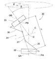
図5に示すように、リンク作動装置29は、パラレルリンク機構30と、このパラレルリンク機構30を作動させる姿勢制御用アクチュエータ31とを有している。図6および図7は、パラレルリンク機構30の斜視図であり、互いに異なる状態を示している。これら図5~図7に示すように、パラレルリンク機構30は、基端側のリンクハブ32と、先端側のリンクハブ33と、基端側のリンクハブ32に対して先端側のリンクハブ33を姿勢変更可能に連結する3組のリンク機構34とを有している。図5では、1組のリンク機構34のみが示されている。リンク機構34の数は、4組以上であっても良い。
各リンク機構34は、基端側の端部リンク部材35、先端側の端部リンク部材36、および中央リンク部材37を有する、4つの回転対偶からなる4節連鎖のリンク機構である。基端側および先端側の端部リンク部材35,36はL字状である。基端側の端部リンク部材35の一端は基端側のリンクハブ32に回転自在に連結され、先端側の端部リンク部材36の一端は先端側のリンクハブ33に回転自在に連結されている。中央リンク部材37は、両端に基端側および先端側の端部リンク部材35,36の他端がそれぞれ回転自在に連結されている。
パラレルリンク機構30は、2つの球面リンク機構を組み合わせた構造であって、基端側のリンクハブ32と基端側の端部リンク部材35の回転対偶、および基端側の端部リンク部材35と中央リンク部材37の回転対偶の中心軸が、基端側の球面リンク中心PA(図5)で交差している。一方、先端側のリンクハブ33と先端側の端部リンク部材36の回転対偶、および先端側の端部リンク部材36と中央リンク部材37の回転対偶の中心軸が、先端側の球面リンク中心PB(図5)で交差している。
また、基端側のリンクハブ32と基端側の端部リンク部材35の各回転対偶から基端側の球面リンク中心PAまでの距離は同じであり、基端側の端部リンク部材35と中央リンク部材37の各回転対偶から基端側の球面リンク中心PAまでの距離も同じである。同様に、先端側のリンクハブ33と先端側の端部リンク部材36の各回転対偶から先端側の球面リンク中心PBまでの距離も同じであり、先端側の端部リンク部材36と中央リンク部材37の各回転対偶から先端側の球面リンク中心PBまでの距離も同じである。基端側および先端側の端部リンク部材35,36と中央リンク部材37との各回転対偶の中心軸は、ある交差角γ(図5)を持っていてもよいし、平行であってもよい。
図8は、図5のVIII-VIII断面図である。同図に、基端側のリンクハブ32と基端側の端部リンク部材35の各回転対偶の中心軸O1と、中央リンク部材37と基端側の端部リンク部材35の各回転対偶の中心軸O2と、基端側の球面リンク中心PAとの関係が示されている。つまり、中心軸O1と中心軸O2とが交差する点が、基端側の球面リンク中心PAである。
先端側のリンクハブ33および先端側の端部リンク部材36の形状ならびに位置関係も図8と同様である(図示せず)。図8では、リンクハブ32(33)と端部リンク部材35(36)との各回転対偶の中心軸O1と、端部リンク部材35(36)と中央リンク部材37との各回転対偶の中心軸O2とが成す角度αが90°となっている。ただし、前記角度αは90°以外であってもよい。
3組のリンク機構34は、幾何学的に同一形状をなす。幾何学的に同一形状とは、図9に示すように、各リンク部材35,36,37を直線で表現した幾何学モデル、すなわち各回転対偶と、これら回転対偶間を結ぶ直線とで表現したモデルが、中央リンク部材37の中央部に対する基端側部分と先端側部分が対称を成す形状であることを言う。図9は、一組のリンク機構34を直線で表現した図である。
この実施形態のパラレルリンク機構30は回転対称タイプで、基端側のリンクハブ32および基端側の端部リンク部材35と、先端側のリンクハブ33および先端側の端部リンク部材36との位置関係が、中央リンク部材37の中心線Cに対して回転対称となる位置関係になっている。中央リンク部材37の中央部は、共通の軌道円上に位置している。
基端側のリンクハブ32と先端側のリンクハブ33と3組のリンク機構34とで、基端側のリンクハブ32に対し先端側のリンクハブ33が直交2軸回りに回転自在な2自由度機構を構成している。言い換えると、基端側のリンクハブ32に対して先端側のリンクハブ33を、回転が2自由度で姿勢変更自在な機構である。この2自由度機構は、コンパクトでありながら、基端側のリンクハブ32に対する先端側のリンクハブ33の可動範囲を広くとれる。
例えば、球面リンク中心PA,PBを通り、リンクハブ32,33と端部リンク部材35,36の各回転対偶の中心軸O1(図8)と直角に交わる直線をリンクハブ32,33の中心軸QA,QBとする。この場合、基端側のリンクハブ32の中心軸QAと先端側のリンクハブ33の中心軸QBとの折れ角θ(図9)の最大値を約±90°とすることができる。また、基端側のリンクハブ32に対する先端側のリンクハブ33の旋回角φ(図9)を0°~360°の範囲に設定できる。折れ角θは、基端側のリンクハブ32の中心軸QAに対して先端側のリンクハブ33の中心軸QBが傾斜した垂直角度のことである。旋回角φは、基端側のリンクハブ32の中心軸QAに対して先端側のリンクハブ33の中心軸QBが傾斜した水平角度のことである。
基端側のリンクハブ32に対する先端側のリンクハブ33の姿勢変更は、基端側のリンクハブ32の中心軸QAと先端側のリンクハブ33の中心軸QBとの交点Oを回転中心として行われる。図6は、基端側のリンクハブ32の中心軸QAと先端側のリンクハブ33の中心軸QBが同一線上にある状態を示す。一方、図7は、基端側のリンクハブ32の中心軸QAに対して先端側のリンクハブ33の中心軸QBが或る作動角をとった状態を示す。姿勢が変化しても、基端側と先端側の球面リンク中心PA,PB間の距離L(図9)は変化しない。
各リンク機構34が以下の条件1~5を満たす場合、幾何学的対称性から基端側のリンクハブ32および基端側の端部リンク部材35と、先端側のリンクハブ33および先端側の端部リンク部材36とは同じに動く。これにより、パラレルリンク機構30は、基端側から先端側へ回転伝達を行う場合、基端側と先端側は同じ回転角になって等速で回転する等速自在継手として機能する。
条件1:各リンク機構34におけるリンクハブ32,33と端部リンク部材35,36との回転対偶の中心軸O1の角度および長さが互いに等しい。
条件2:リンクハブ32,33と端部リンク部材35,36との回転対偶の中心軸O1および端部リンク部材35,36と中央リンク部材37との回転対偶の中心軸O2が、基端側および先端側において球面リンク中心PA,PBで交差する。
条件3:基端側の端部リンク部材35と先端側の端部リンク部材36の幾何学的形状が等しい。
条件4:中央リンク部材37における基端側部分と先端側部分の幾何学的形状が等しい。
条件5:中央リンク部材37の対称面に対して、中央リンク部材37と端部リンク部材35,36との角度位置関係が基端側と先端側とで同じである。
条件2:リンクハブ32,33と端部リンク部材35,36との回転対偶の中心軸O1および端部リンク部材35,36と中央リンク部材37との回転対偶の中心軸O2が、基端側および先端側において球面リンク中心PA,PBで交差する。
条件3:基端側の端部リンク部材35と先端側の端部リンク部材36の幾何学的形状が等しい。
条件4:中央リンク部材37における基端側部分と先端側部分の幾何学的形状が等しい。
条件5:中央リンク部材37の対称面に対して、中央リンク部材37と端部リンク部材35,36との角度位置関係が基端側と先端側とで同じである。
図5~図7に示すように、基端側のリンクハブ32は、基端部材40と、この基端部材40と一体に設けられた3個の回転軸連結部材41とを有している。図8に示すように、基端部材40の中央部に円形の貫通孔40が形成され、この貫通孔40aの周囲に3個の回転軸連結部材41が円周方向に等間隔で配置されている。貫通孔40aの中心は、基端側のリンクハブ32の中心軸QA(図5)上に位置する。各回転軸連結部材41には、軸心が基端側のリンクハブ32の中心軸QAと交差する回転軸42が回転自在に連結されている。この回転軸42に、基端側の端部リンク部材35の一端が連結されている。
回転軸42は、2個の軸受43を介して回転軸連結部材41に回転自在に支持されている。軸受43は、例えば深溝玉軸受、アンギュラ玉軸受等の玉軸受である。軸受43は、筒状の回転軸連結部材41の中空孔44に嵌合状態で設置され、圧入、接着、加締め等の方法で固定されている。他の回転対偶部に設けられる軸受の種類および設置方法も同様である。
回転軸42には、基端側の端部リンク部材35の一端と後述の扇形のかさ歯車45とが結合されており、両者は回転軸42と一体に回転する。詳しくは、基端側の端部リンク部材35の一端に切欠き部46が形成されており、この切欠き部46の両側部分である内外の回転軸支持部47,48間に回転軸連結部材41が配置されている。かさ歯車45は、内側の回転軸支持部47の内側面に当接して配置されている。
回転軸42を内側から、かさ歯車45に形成された貫通孔、内側の回転軸支持部47に形成された貫通孔、軸受43の内輪、外側の回転軸支持部48に形成された貫通孔の順に挿通する。その後、回転軸42の頭部42aと回転軸42のねじ部42bに螺着したナット50とで、かさ歯車45、内外の回転軸支持部47,48、および軸受43の内輪を挟み込んで結合する。内外の回転軸支持部47,48と軸受43との間には、スペーサ51,52が介在されており、ナット50の螺着時に軸受43に予圧が付与される。
基端側の端部リンク部材35の他端には、回転軸55が結合されている。回転軸55は、2つの軸受53を介して中央リンク部材37の一端に回転自在に連結されている。詳しくは、基端側の端部リンク部材35の他端に切欠き部56が形成されており、この切欠き部56の両側部分である内外の回転軸支持部57,58間に中央リンク部材37の一端が配置されている。
回転軸55を外側から、外側の回転軸支持部58に形成された貫通孔、軸受53の内輪、内側の回転軸支持部57に形成された貫通孔の順に挿通する。その後、回転軸55の頭部55aと回転軸55のねじ部55bに螺着したナット60とで、内外の回転軸支持部57,58、および軸受53の内輪を挟み込んで結合する。内外の回転軸支持部57,58と軸受53との間にスペーサ61,62が介在されており、ナット60の螺着時に軸受53に予圧が付与される。
図6、図7に示すように、先端側のリンクハブ33は、先端部材70と、この先端部材70の内面に円周方向等配で設けられた3個の回転軸連結部材71とを有している。回転軸連結部材71が配置される円周の中心は、先端側のリンクハブ33の中心軸QB上に位置する。各回転軸連結部材71には、軸心がリンクハブ中心軸QBと交差する回転軸73が回転自在に連結されている。この先端側のリンクハブ33の回転軸73に、先端側の端部リンク部材36の一端が連結されている。
先端側の端部リンク部材36の他端には、中央リンク部材37の他端に回転自在に連結された回転軸75が連結されている。先端側のリンクハブ33の回転軸73および中央リンク部材37の回転軸75は、上述の回転軸42,55と同様に、2個の軸受(図示せず)を介して回転軸連結部材71および中央リンク部材37の他端にそれぞれ回転自在に連結されている。
図5に示すように、パラレルリンク機構30は、基端部材40を複数本のシャフト81を介してベース部材80と連結することで、第1の回転機構21に設置されている。基端側のリンクハブ32の中心軸QAと、第1の回転機構21の回転軸心21bとは同一線上に位置する。ベース部材80は、第1の回転機構21の回転部分21aに固定されている。基端部材40の外周縁とベース部材80の外周縁間に、カバー82が取り付けられている。基端部材40とベース部材80との間は、このカバー82により外部から遮蔽された遮蔽空間83となっている。
パラレルリンク機構30を作動させる姿勢制御用アクチュエータ31は、遮蔽空間83に配置され、基端部材40に取り付けられている。姿勢制御用アクチュエータ31の数は、リンク機構34と同数の3個である。姿勢制御用アクチュエータ31は、例えば、モータのようなロータリアクチュエータである。姿勢制御用アクチュエータ31の回転出力軸31aに取り付けられたかさ歯車76と、基端側のリンクハブ32の回転軸42に取り付けられた扇形のかさ歯車45とが噛み合っている。つまり、かさ歯車76と扇形のかさ歯車45とで軸直交型の減速機77を構成する。かさ歯車以外の機構(例えばウォーム機構)を用いて軸直交型の減速機を構成してもよい。
第2実施形態では、リンク機構34と同数の姿勢制御用アクチュエータ31が設けられているが、3組のリンク機構34のうち少なくとも2組に姿勢制御用アクチュエータ31が設けられていればよい。これにより、基端側のリンクハブ32に対する先端側のリンクハブ33の姿勢を確定することができる。
リンク作動装置29は、各姿勢制御用アクチュエータ31を回転駆動することで、パラレルリンク機構30を作動させる。詳しくは、姿勢制御用アクチュエータ31が回転駆動すると、その回転が軸直交型の減速機77を介して減速されて回転軸42に伝達され、基端側のリンクハブ32に対する基端側の端部リンク部材35の角度が変更する。これにより、基端側のリンクハブ32に対する先端側のリンクハブ33の位置および姿勢が決まる。基端側のリンクハブ32の中心軸QAと第1の回転機構21の回転軸心21bとが同一線上に位置するため、座標計算が容易である。
また、基端側のリンクハブ32の中心軸QAと第1の回転機構21の回転軸心21bとが同一線上に位置すると、作業者が作業装置1の動作をイメージし易いので、簡単に操作できる。例えば、直動ユニット3で決定される3自由度の位置を固定し、かつ回転ユニット4で決定される3自由度の角度のうち2自由度の角度を固定し、残りの1自由度の角度(例えば、先端側のリンクハブ33の中心軸QB周りの角度)だけを変更してエンドエフェクト5の姿勢を変えながら作業を行うことができる。
上述のように、リンク作動装置29は可動範囲が広くスムーズな動作が可能であるので、回転ユニット4にリンク作動装置29が含まれていると、高速できめ細かい作業を行うことができる。また、リンク作動装置29はコンパクトな構成でありながら可動範囲が広いので、作業装置1の全体がコンパクトな構成になる。
この第2実施形態のように、リンク作動装置29の基端側に第1の回転機構21を配置し、先端側のリンクハブ33にエンドエフェクタ5を搭載した構成であると、リンク作動装置29の負荷を軽減できる。このため、リンク作動装置29のコンパクト化、軽量化を実現できる。リンク作動装置29のパラレルリンク機構30は等速自在継手の構成である。したがって、リンク作動装置29と第1の回転機構21との協調制御により、エンドエフェクト5の姿勢を、先端側のリンクハブ33の中心軸QB周りの角度のみ変えながら行う作業が容易である。ただし、姿勢制御用アクチュエータ31に接続するケーブルについて考慮する必要があるので、回転角は制限される。
図10の第3実施形態は、第1の回転機構21とリンク作動装置29の並びとを図5の第2実施形態とは逆にした回転ユニット4を示す。第3実施形態の場合、リンク作動装置29の先端側のリンクハブ33の中心軸QBと、第1の回転機構21の回転軸心21bとが同一線上に位置している。その他の構成は、図5の第2実施形態と同じである。
第3実施形態の回転ユニット4によれば、姿勢制御用アクチュエータ31に接続されるケーブルの配線が容易であり、回転角の制限を受け難い。反面、リンク作動装置29の負荷が増大するという欠点がある。その他は、図5の第2実施形態と同じ作用・効果が得られる。
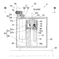
図11~図13はこの発明の第4実施形態を示す。図11に示すように、この作業装置1も、図4の第2実施形態と同様に、回転ユニット4が、1自由度の回転機構である第1の回転機構21と、2自由度の回転機構であるリンク作動装置29とを有している。第4実施形態の作業装置1が、図4の第2実施形態と異なる点は、リンク作動装置29の各姿勢制御用アクチュエータ31の中心部に、第1の回転機構21が配置されていることである。
図12に示すように、第1の回転機構21は、ベース部材80に固定された固定部分90と、リンク作動装置29の基端部材40に固定された回転部分91と、固定部分90に対して回転部分91を回転自在に支持する2つの軸受92と、固定部分90に設置された駆動源であるモータ93と、このモータ93の回転を回転部分91に伝達する一対の平歯車94,95とを備えている。
ベース部材80は、回転ユニット取付部材20に固定されている。固定部分90は、ベース部材80に固定された断面馬蹄形の第1取付部材96と、この第1取付部材96に底部97aで固定された第2取付部材97とを有している。第2取付部材97は、底部97aの外周縁から図12の上方に延びた筒状部97bを有している。回転部分91は、その回転軸心91aが基端側のリンクハブ32の中心軸QAと同軸上に位置するように、基端側のリンクハブ32の基端部材40に固定されている。2つの軸受92は、第2取付部材97の筒状部97bの内周に配置されている。
モータ93は、断面馬蹄形の第1取付部材96の凹部96aに配置され、第2取付部材97の底部97aに固定されている。モータ93の出力軸93aは、第2取付部材97の底部97aを貫通して上方へ延び、その上端に駆動側の平歯車94が取り付けられている。駆動側の平歯車94は、回転部分91に取り付けられた従動側の平歯車95と噛み合っている。従動側の平歯車95は、回転部分91の外周に嵌合している。回転部分91の下端に、ねじ部が設けられており、このねじ部に螺合したナット98によって、平歯車95が回転部分91に締付け固定されている。
第2取付部材97の底部97a、回転部分91および基端部材40には、回転部分91の回転軸心91aに沿って貫通する配線用孔100,101,102がそれぞれ設けられている。基端部材40の外周縁には、ベース部材80の外周縁近傍にかけて延びるカバー82が取り付けられている。カバー82とベース部材80とは結合されていない。
図5の第2実施形態と同様に、リンク作動装置29の3つの姿勢制御用アクチュエータ31は、基端部材40における仮想の円周上に配置され、各姿勢制御用アクチュエータ31の回転出力軸31aの回転駆動力は軸直交型の減速機77を介してリンク機構34に伝達される。このような姿勢制御用アクチュエータ31の配置によれば、第4実施形態のように、各姿勢制御用アクチュータ31の並びの中心部に第1の回転機構21を配置することができる。これにより、回転ユニット4がコンパクトな構成になる。
モータ93が駆動すると、回転部分91と共にリンク作動装置29の全体およびカバー82が回転する。配線用孔100,101,102に配線を通すことで、リンク機構34に干渉することなく、リンク作動装置29の内部空間側からエンドエフェクタ5に配線を繋げることができる。このため、姿勢制御用アクチュエータ31に接続されるケーブルの配線に関する制約が少なくなる。リンク作動装置29の内部空間とは、基端側のリンクハブ32、先端側のリンクハブ33および各リンク機構34で囲まれた空間を指す。
図14は、この発明の第5実施形態にかかる作業装置の回転ユニットの要部の正面図である。第5実施形態の回転ユニット4では、リンク作動装置29の各姿勢制御用アクチュエータ31の中心部に、第1の回転機構21が配置されている。この点は図12に示す第4実施形態と同じであるが、第1の回転機構21の駆動源が中空軸モータ110である点が、図12に示す第4実施形態と異なっている。
中空軸モータ110は、そのモータ本体110aがモータ取付部材111を介してベース部材80に固定されている。中空軸モータ110の出力軸110bに、基端側のリンクハブ32の基端部材40が固定されている。中空軸モータ110は、モータ本体110aおよび出力軸110bを軸方向に貫通する配線用孔112を有している。また、基端側のリンクハブ32の基端部材40にも、配線用孔112と同軸上に配線用孔113が設けられている。これ以外の構成は、図12に示す第4実施形態と同じであり、第4実施形態と同様の作用、効果が得られる。
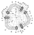
図15~図17は、この発明の第6実施形態にかかる双腕型の作業装置の概略構成を示す。図15の正面図、図16の斜視図に示すように、この双腕型作業装置120では、図11に示す第4実施形態の作業装置1が幾何学的に対称となるように2つ並べて配置されている。各作業装置1の架台2,2は、それぞれの水平部2a,2aの先端同士が繋がっており、全体で門形の架台2Aとなっている。この第6実施形態は、図11に示す第4実施形態の作業装置1を使用しているが、他の実施形態の作業装置を用いてもよい。
このように、作業装置1を2つ並べた双腕型とすることで、人が両手で行うような作業が可能となる。これにより、人の代わりとなる作業、特に部品の組立てのような作業を行うことができる。
2つの作業装置1,1が門形の架台2Aに設置されていると、作業装置1,1の下を作業対象のワーク7が通過することができる。例えば、ワーク載置台6を図15における紙面と直交する方向にワーク7を搬送可能なコンベア装置とし、そのコンベアライン上に作業装置1,1を設置することができる。また、作業装置1,1の幅方向の可動範囲を架台2Aの幅方向内に制限することができるので、作業装置1,1の占有面積が小さくて済む。さらに、作業装置1,1の可動範囲が制限されるので、作業者が作業装置1,1の横に居ても安心して作業することができる。
図17は、図15、図16に示す双腕型作業装置120の直動ユニット3,3の平面図である。これらの直動ユニット3,3は、図1、図4、図11に示す各作業装置1の直動ユニット3と同様に、第1の直動アクチュエータ11および第2の直動アクチュータ12の各モータ11b,12bが、直動アクチュエータ11,12の中心軸上に配置されている。
図18は、直動ユニット3,3の別の実施形態を示す平面図である。図18の直動ユニット3,3は、第1の直動アクチュエータ11および第2の直動アクチュータ12の各モータ11b,12bが、直動アクチュエータ11,12の中心軸からオフセットして配置されており、モータ11b,12bの回転がチェーンのような動力伝達手段121を介して直動アクチュエータ11,12の駆動部へ伝達されている。このように、双腕型作業装置120の仕様に応じて、直動ユニット3を図17の第6実施形態または図18の第7実施形態に変更することが可能である。直動ユニット3と回転ユニット4が別々に設けられているので、このような変更が容易である。
以上のとおり、図面を参照しながら好適な実施形態を説明したが、本発明は、以上の実施形態に限定されるものでなく、本発明の要旨を逸脱しない範囲内で、種々の追加、変更または削除が可能である。したがって、そのようなものも本発明の範囲内に含まれる。
1…作業装置
2…架台
2A…門形の架台
3…直動ユニット
4…回転ユニット
5…エンドエフェクタ
11…第1の直動アクチュエータ
11a…ステージ
12…第2の直動アクチュエータ
12a…ステージ
13…第3の直動アクチュエータ
13a…ステージ(直動ユニットの出力部)
20…回転ユニット取付部材(回転ユニットの基部)
21…第1の回転機構
22…第2の回転機構
23…第3の回転機構
23a…ステージ(回転ユニットの出力部)
29…リンク作動装置
31…姿勢制御用アクチュエータ
32…基端側のリンクハブ
33…先端側のリンクハブ
34…リンク機構
35…基端側の端部リンク部材
36…先端側の端部リンク部材
37…中央リンク部材
100,101,102,112,113…配線用孔
120…双腕型作業装置
O1…リンクハブと端部リンク部材の回転対偶の中心軸
O2…端部リンク部材と中央リンク部材の回転対偶の中心軸
PA,PB…球面リンク中心
QA,QB…リンクハブの中心軸
S…作業空間
Claims (10)
- エンドエフェクタを用いて作業を行う6自由度の作業装置であって、
3つの直動アクチュエータを組み合わせた3自由度の直動ユニットと、
1自由度以上の回転自由度を持つ複数の回転機構を組み合わせた3自由度の回転ユニットと、を備え、
前記直動ユニットの基部が、前記作業装置の架台に固定され、
前記回転ユニットの基部が前記直動ユニットの出力部に固定され、かつ前記回転ユニットの出力部に前記エンドエフェクタが搭載されている作業装置。 - 請求項1に記載の作業装置において、前記直動ユニットの前記各直動アクチュエータは、それぞれの進退部分からなるステージが、前記エンドエフェクタによって作業が行われる作業空間に対して外側を向くように配置されている作業装置。
- 請求項1または請求項2に記載の作業装置において、
前記回転ユニットは、前記複数の回転機構のうちの少なくとも1つが2自由度のリンク作動装置であり、
このリンク作動装置は、基端側のリンクハブに対し先端側のリンクハブが3組以上のリンク機構を介して姿勢を変更可能に連結され、
前記各リンク機構は、それぞれ前記基端側のリンクハブおよび前記先端側のリンクハブに一端が回転可能に連結された基端側および先端側の端部リンク部材と、これら基端側および先端側の端部リンク部材の他端に両端がそれぞれ回転可能に連結された中央リンク部材とを有し、
前記3組以上のリンク機構のうちの2組以上のリンク機構に、前記基端側のリンクハブに対する前記先端側のリンクハブの姿勢を任意に変更させる姿勢制御用アクチュエータが設けられている作業装置。 - 請求項3に記載の作業装置において、
前記基端側のリンクハブと前記基端側の端部リンク部材の各回転対偶の中心軸、および前記基端側の端部リンク部材と前記中央リンク部材の各回転対偶の中心軸がそれぞれ交差する点が基端側の球面リンク中心と称され、
この基端側の球面リンク中心を通り前記基端側のリンクハブと前記基端側の端部リンク部材の各回転対偶の中心軸と直角に交わる直線が基端側のリンクハブの中心軸と称され、
前記先端側のリンクハブと前記先端側の端部リンク部材の各回転対偶の中心軸、および前記先端側の端部リンク部材と前記中央リンク部材の各回転対偶の中心軸がそれぞれ交差する点が先端側の球面リンク中心と称され、
この先端側の球面リンク中心を通り前記先端側のリンクハブと前記先端側の端部リンク部材の各回転対偶の中心軸と直角に交わる直線が先端側のリンクハブの中心軸と称され、
前記基端側のリンクハブの中心軸または前記先端側のリンクハブの中心軸と、前記リンク作動装置以外の他の回転機構の回転軸心とが同一線上に位置する作業装置。 - 請求項4に記載の作業装置において、前記リンク作動装置の前記基端側のリンクハブに前記他の回転機構の回転部分が直接または間接に結合され、
前記リンク作動装置の前記先端側のリンクハブに、前記エンドエフェクタが搭載されている作業装置。 - 請求項5に記載の作業装置において、前記リンク作動装置の前記2つ以上の姿勢制御用アクチュエータはロータリアクチュエータであって、
前記ロータリアクチュエータの回転出力軸が、前記基端側のリンクハブの中心軸と平行となるように配置され、
前記回転出力軸の回転駆動力が、軸直交型の減速機を介して前記リンク機構に伝達され、
前記各姿勢制御用アクチュエータの並びの中心部に、前記他の回転機構が配置されている作業装置。 - 請求項4から請求項6のいずれか一項に記載の作業装置において、前記他の回転機構は、少なくとも回転する部分に軸方向に貫通する配線用孔を有する作業装置。
- 請求項1から請求項7のいずれか一項に記載の作業装置において、前記直動ユニットの前記出力部に対する前記回転ユニットの前記基部の取付角度が変更可能である作業装置。
- 請求項1から請求項8のいずれか一項に記載の作業装置が、互いに幾何学的に対称となるように2つ並べて配置された双腕型である作業装置。
- 請求項9に記載の作業装置において、前記2つの作業装置が門形の前記架台に設置されている作業装置。
Priority Applications (3)
| Application Number | Priority Date | Filing Date | Title |
|---|---|---|---|
| CN201780024365.XA CN109070341A (zh) | 2016-04-20 | 2017-04-10 | 作业装置和双臂型作业装置 |
| EP17785845.3A EP3446836B1 (en) | 2016-04-20 | 2017-04-10 | Work device and dual-arm work device |
| US16/164,486 US11154994B2 (en) | 2016-04-20 | 2018-10-18 | Work device and dual-arm work device |
Applications Claiming Priority (2)
| Application Number | Priority Date | Filing Date | Title |
|---|---|---|---|
| JP2016-084171 | 2016-04-20 | ||
| JP2016084171A JP6719956B2 (ja) | 2016-04-20 | 2016-04-20 | 双腕型作動装置 |
Related Child Applications (1)
| Application Number | Title | Priority Date | Filing Date |
|---|---|---|---|
| US16/164,486 Continuation US11154994B2 (en) | 2016-04-20 | 2018-10-18 | Work device and dual-arm work device |
Publications (1)
| Publication Number | Publication Date |
|---|---|
| WO2017183505A1 true WO2017183505A1 (ja) | 2017-10-26 |
Family
ID=60115942
Family Applications (1)
| Application Number | Title | Priority Date | Filing Date |
|---|---|---|---|
| PCT/JP2017/014683 WO2017183505A1 (ja) | 2016-04-20 | 2017-04-10 | 作業装置および双腕型作業装置 |
Country Status (5)
| Country | Link |
|---|---|
| US (1) | US11154994B2 (ja) |
| EP (1) | EP3446836B1 (ja) |
| JP (1) | JP6719956B2 (ja) |
| CN (1) | CN109070341A (ja) |
| WO (1) | WO2017183505A1 (ja) |
Families Citing this family (14)
| Publication number | Priority date | Publication date | Assignee | Title |
|---|---|---|---|---|
| JP6067805B1 (ja) * | 2015-09-07 | 2017-01-25 | Ntn株式会社 | リンク作動装置を用いた複合作業装置 |
| JP6719956B2 (ja) * | 2016-04-20 | 2020-07-08 | Ntn株式会社 | 双腕型作動装置 |
| JP6765284B2 (ja) | 2016-11-10 | 2020-10-07 | Ntn株式会社 | 作動装置および双腕型作動装置 |
| JP2018075689A (ja) | 2016-11-11 | 2018-05-17 | Ntn株式会社 | 作動装置および双腕型作動装置 |
| WO2019069666A1 (ja) | 2017-10-02 | 2019-04-11 | カルソニックカンセイ株式会社 | 空調装置 |
| JP7140508B2 (ja) * | 2018-02-26 | 2022-09-21 | Ntn株式会社 | パラレルリンク機構を用いた作業装置およびその制御方法 |
| JP7289644B2 (ja) * | 2018-12-07 | 2023-06-12 | Ntn株式会社 | 作業装置 |
| US20220166288A1 (en) * | 2019-03-22 | 2022-05-26 | Ntn Corporation | Parallel link mechanism and link actuation device |
| CN109932692A (zh) * | 2019-03-28 | 2019-06-25 | 尹建霞 | 一种共轴双向伺服雷达转台 |
| CN110919638B (zh) * | 2019-11-15 | 2021-11-02 | 华中科技大学 | 一种3+4构型双臂协作机器人加工系统及方法 |
| JP2022082090A (ja) * | 2020-11-20 | 2022-06-01 | Ntn株式会社 | 作業装置 |
| CN113146590A (zh) * | 2021-05-21 | 2021-07-23 | 莱茵科斯特智能科技(青岛)有限公司 | 一种用于安装产品附件的工作站及用于安装附件的机械手 |
| WO2022269693A1 (ja) * | 2021-06-21 | 2022-12-29 | 東京ロボティクス株式会社 | リンク機構、ロボットアーム及び双腕ロボット |
| JP2023047742A (ja) * | 2021-09-27 | 2023-04-06 | Ntn株式会社 | 作業装置 |
Citations (9)
| Publication number | Priority date | Publication date | Assignee | Title |
|---|---|---|---|---|
| JPH07178684A (ja) * | 1993-12-22 | 1995-07-18 | Toshiba Corp | ロボットアーム |
| JPH0810935A (ja) * | 1994-06-27 | 1996-01-16 | Riyouei Eng Kk | 自動バリ取り装置 |
| JP2002336994A (ja) * | 2001-03-14 | 2002-11-26 | Hitachi Zosen Corp | 搬送装置及び溶接装置 |
| JP2005329521A (ja) | 2004-05-21 | 2005-12-02 | Denso Wave Inc | 多関節型ロボット |
| JP2009202331A (ja) * | 2007-07-27 | 2009-09-10 | Nsk Ltd | マニピュレータ、マニピュレータの駆動方法、マニピュレータシステム及び微小操作対象物の操作方法 |
| WO2010002043A1 (en) * | 2008-06-30 | 2010-01-07 | Seoul National University Industry Foundation | Robot having rotatable arm |
| JP4528312B2 (ja) | 2007-02-02 | 2010-08-18 | 川田工業株式会社 | 双腕ロボットの肩幅空間制限装置及びその装置を具えた双腕ロボット |
| JP2014119069A (ja) * | 2012-12-18 | 2014-06-30 | Ntn Corp | リンク作動装置 |
| JP2015085427A (ja) * | 2013-10-30 | 2015-05-07 | 株式会社デンソーウェーブ | 6軸ロボットの各軸角度決定方法及び6軸ロボットの制御装置 |
Family Cites Families (37)
| Publication number | Priority date | Publication date | Assignee | Title |
|---|---|---|---|---|
| US4723460A (en) * | 1984-04-12 | 1988-02-09 | Rosheim Mark E | Robot wrist actuator |
| DE3626610A1 (de) * | 1986-08-06 | 1988-02-18 | Fibro Gmbh | Portalsystem |
| JP2005144627A (ja) * | 2003-11-18 | 2005-06-09 | Ntn Corp | リンク作動装置 |
| WO2005053913A1 (ja) * | 2003-12-03 | 2005-06-16 | Ntn Corporation | リンク作動装置 |
| US7971505B2 (en) * | 2004-03-11 | 2011-07-05 | Ntn Corporation | Link actuating device |
| US7501603B2 (en) * | 2005-03-23 | 2009-03-10 | Vojislav Kalanovic | Positioning apparatus and method incorporating modular gimbal unit and jewelry processing system incorporating the positioning apparatus |
| JP2010260139A (ja) * | 2009-05-08 | 2010-11-18 | Ntn Corp | 遠隔操作型加工ロボット |
| CN101559597B (zh) * | 2009-05-12 | 2011-04-20 | 哈尔滨工程大学 | 多功能龙门式七轴工业机器人 |
| JP5528207B2 (ja) * | 2010-05-19 | 2014-06-25 | Ntn株式会社 | リンク作動装置 |
| KR101213452B1 (ko) * | 2010-08-27 | 2012-12-18 | 한양대학교 에리카산학협력단 | 4자유도 병렬기구를 이용한 마스터?슬레이브 시스템 |
| CN101947781A (zh) * | 2010-08-30 | 2011-01-19 | 苏州博实机器人技术有限公司 | 一种模块化多控制直角坐标机器人 |
| JP5951224B2 (ja) * | 2011-11-02 | 2016-07-13 | Ntn株式会社 | リンク作動装置の原点位置初期設定方法およびリンク作動装置 |
| EP2775169B1 (en) * | 2011-11-04 | 2017-10-04 | NTN Corporation | Parallel link mechanism, constant velocity universal joint, and link actuator |
| US9522469B2 (en) * | 2012-03-23 | 2016-12-20 | Ntn Corporation | Link actuation device |
| CN102785239B (zh) * | 2012-07-23 | 2015-04-29 | 东莞市李群自动化设备有限公司 | 一种六自由度工业机器人 |
| EP2979823B1 (en) * | 2013-03-26 | 2019-07-10 | NTN Corporation | Linking apparatus control device |
| JP6104701B2 (ja) * | 2013-05-16 | 2017-03-29 | Ntn株式会社 | リンク作動装置 |
| DE102013225116A1 (de) * | 2013-12-06 | 2015-07-16 | Robert Bosch Gmbh | Handhabungseinheit |
| JP6289973B2 (ja) * | 2014-03-31 | 2018-03-07 | Ntn株式会社 | パラレルリンク機構およびリンク作動装置 |
| JP6453066B2 (ja) * | 2014-12-05 | 2019-01-16 | Ntn株式会社 | リンク作動装置の制御方法 |
| CN204414100U (zh) * | 2015-01-13 | 2015-06-24 | 旭东机械(昆山)有限公司 | 液晶面板装箱用四轴手臂模组 |
| JP6527782B2 (ja) * | 2015-08-10 | 2019-06-05 | Ntn株式会社 | パラレルリンク機構を用いた作業装置 |
| JP6067805B1 (ja) * | 2015-09-07 | 2017-01-25 | Ntn株式会社 | リンク作動装置を用いた複合作業装置 |
| JP6602620B2 (ja) * | 2015-09-24 | 2019-11-06 | Ntn株式会社 | 組合せ型リンク作動装置 |
| JP6262193B2 (ja) * | 2015-12-24 | 2018-01-17 | Ntn株式会社 | リンク作動装置 |
| TWI623345B (zh) * | 2016-01-15 | 2018-05-11 | 崔文德 | 弧桿組合機構 |
| JP6719956B2 (ja) * | 2016-04-20 | 2020-07-08 | Ntn株式会社 | 双腕型作動装置 |
| JP6765221B2 (ja) * | 2016-05-30 | 2020-10-07 | Ntn株式会社 | パラレルリンク機構を用いた作業装置 |
| JP6275196B2 (ja) * | 2016-06-05 | 2018-02-07 | Ntn株式会社 | リンク作動装置の操作装置およびリンク作動システム |
| EP3470704B1 (en) * | 2016-06-08 | 2021-04-28 | NTN Corporation | Link operating device |
| JP6799950B2 (ja) * | 2016-06-15 | 2020-12-16 | Ntn株式会社 | 作業装置および双腕型作業装置 |
| JP6765284B2 (ja) * | 2016-11-10 | 2020-10-07 | Ntn株式会社 | 作動装置および双腕型作動装置 |
| JP2018075689A (ja) * | 2016-11-11 | 2018-05-17 | Ntn株式会社 | 作動装置および双腕型作動装置 |
| JP6800044B2 (ja) * | 2017-02-24 | 2020-12-16 | Ntn株式会社 | リンク作動装置の制御装置および制御方法 |
| JP6498738B1 (ja) * | 2017-09-26 | 2019-04-10 | Ntn株式会社 | リンク作動装置 |
| KR101956617B1 (ko) * | 2017-11-23 | 2019-03-12 | (주)한국미래기술 | 병렬형 집적 구동장치 |
| US20200298425A1 (en) * | 2019-02-25 | 2020-09-24 | The Chinese University Of Hong Kong | Morphable inertial appemdage, systems and associated methods |
-
2016
- 2016-04-20 JP JP2016084171A patent/JP6719956B2/ja active Active
-
2017
- 2017-04-10 EP EP17785845.3A patent/EP3446836B1/en active Active
- 2017-04-10 WO PCT/JP2017/014683 patent/WO2017183505A1/ja active Application Filing
- 2017-04-10 CN CN201780024365.XA patent/CN109070341A/zh active Pending
-
2018
- 2018-10-18 US US16/164,486 patent/US11154994B2/en active Active
Patent Citations (9)
| Publication number | Priority date | Publication date | Assignee | Title |
|---|---|---|---|---|
| JPH07178684A (ja) * | 1993-12-22 | 1995-07-18 | Toshiba Corp | ロボットアーム |
| JPH0810935A (ja) * | 1994-06-27 | 1996-01-16 | Riyouei Eng Kk | 自動バリ取り装置 |
| JP2002336994A (ja) * | 2001-03-14 | 2002-11-26 | Hitachi Zosen Corp | 搬送装置及び溶接装置 |
| JP2005329521A (ja) | 2004-05-21 | 2005-12-02 | Denso Wave Inc | 多関節型ロボット |
| JP4528312B2 (ja) | 2007-02-02 | 2010-08-18 | 川田工業株式会社 | 双腕ロボットの肩幅空間制限装置及びその装置を具えた双腕ロボット |
| JP2009202331A (ja) * | 2007-07-27 | 2009-09-10 | Nsk Ltd | マニピュレータ、マニピュレータの駆動方法、マニピュレータシステム及び微小操作対象物の操作方法 |
| WO2010002043A1 (en) * | 2008-06-30 | 2010-01-07 | Seoul National University Industry Foundation | Robot having rotatable arm |
| JP2014119069A (ja) * | 2012-12-18 | 2014-06-30 | Ntn Corp | リンク作動装置 |
| JP2015085427A (ja) * | 2013-10-30 | 2015-05-07 | 株式会社デンソーウェーブ | 6軸ロボットの各軸角度決定方法及び6軸ロボットの制御装置 |
Non-Patent Citations (1)
| Title |
|---|
| See also references of EP3446836A4 |
Also Published As
| Publication number | Publication date |
|---|---|
| US11154994B2 (en) | 2021-10-26 |
| EP3446836A1 (en) | 2019-02-27 |
| JP2017193009A (ja) | 2017-10-26 |
| EP3446836A4 (en) | 2019-04-24 |
| CN109070341A (zh) | 2018-12-21 |
| US20190047159A1 (en) | 2019-02-14 |
| EP3446836B1 (en) | 2023-04-05 |
| JP6719956B2 (ja) | 2020-07-08 |
Similar Documents
| Publication | Publication Date | Title |
|---|---|---|
| WO2017183505A1 (ja) | 作業装置および双腕型作業装置 | |
| US11420322B2 (en) | Working device and double-arm type working device | |
| JP6502115B2 (ja) | リンク作動装置を用いた多関節ロボット | |
| US11247329B2 (en) | Work device and dual-arm work device | |
| JP2022122889A (ja) | 外科用ロボットアーム | |
| WO2018181040A1 (ja) | 多関節ロボット | |
| WO2016021099A1 (ja) | パラレルリンクロボットおよびパラレルリンク構造 | |
| US11130225B2 (en) | Working device and double-arm type working device | |
| WO2017043420A1 (ja) | リンク作動装置を用いた複合作業装置 | |
| JP6576646B2 (ja) | リンク作動装置を用いた多関節ロボット | |
| JP6883073B2 (ja) | リンク作動装置を用いた多関節ロボット | |
| WO2016084685A1 (ja) | パラレルリンク機構を用いた作業装置 | |
| WO2018088446A1 (ja) | 作業装置および双腕型作業装置 | |
| JP7260987B2 (ja) | 双腕型の作業装置 | |
| JP2016153159A (ja) | パラレルリンク機構を用いた作業装置 | |
| WO2019078283A1 (ja) | 双腕型の作業装置 | |
| WO2022107652A1 (ja) | 作業装置 | |
| JP7289644B2 (ja) | 作業装置 | |
| JP2018167365A (ja) | ロボットアーム | |
| WO2016080472A1 (ja) | パラレルリンク機構を用いた作業装置 |
Legal Events
| Date | Code | Title | Description |
|---|---|---|---|
| NENP | Non-entry into the national phase |
Ref country code: DE |
|
| WWE | Wipo information: entry into national phase |
Ref document number: 2017785845 Country of ref document: EP |
|
| ENP | Entry into the national phase |
Ref document number: 2017785845 Country of ref document: EP Effective date: 20181120 |
|
| 121 | Ep: the epo has been informed by wipo that ep was designated in this application |
Ref document number: 17785845 Country of ref document: EP Kind code of ref document: A1 |