WO2017110310A1 - 二重容器 - Google Patents
二重容器 Download PDFInfo
- Publication number
- WO2017110310A1 WO2017110310A1 PCT/JP2016/083838 JP2016083838W WO2017110310A1 WO 2017110310 A1 WO2017110310 A1 WO 2017110310A1 JP 2016083838 W JP2016083838 W JP 2016083838W WO 2017110310 A1 WO2017110310 A1 WO 2017110310A1
- Authority
- WO
- WIPO (PCT)
- Prior art keywords
- layer body
- mouth
- ring
- outer layer
- intermittent
- Prior art date
Links
Images


Classifications
-
- B—PERFORMING OPERATIONS; TRANSPORTING
- B65—CONVEYING; PACKING; STORING; HANDLING THIN OR FILAMENTARY MATERIAL
- B65D—CONTAINERS FOR STORAGE OR TRANSPORT OF ARTICLES OR MATERIALS, e.g. BAGS, BARRELS, BOTTLES, BOXES, CANS, CARTONS, CRATES, DRUMS, JARS, TANKS, HOPPERS, FORWARDING CONTAINERS; ACCESSORIES, CLOSURES, OR FITTINGS THEREFOR; PACKAGING ELEMENTS; PACKAGES
- B65D1/00—Containers having bodies formed in one piece, e.g. by casting metallic material, by moulding plastics, by blowing vitreous material, by throwing ceramic material, by moulding pulped fibrous material, by deep-drawing operations performed on sheet material
- B65D1/02—Bottles or similar containers with necks or like restricted apertures, designed for pouring contents
- B65D1/0207—Bottles or similar containers with necks or like restricted apertures, designed for pouring contents characterised by material, e.g. composition, physical features
- B65D1/0215—Bottles or similar containers with necks or like restricted apertures, designed for pouring contents characterised by material, e.g. composition, physical features multilayered
-
- B—PERFORMING OPERATIONS; TRANSPORTING
- B65—CONVEYING; PACKING; STORING; HANDLING THIN OR FILAMENTARY MATERIAL
- B65D—CONTAINERS FOR STORAGE OR TRANSPORT OF ARTICLES OR MATERIALS, e.g. BAGS, BARRELS, BOTTLES, BOXES, CANS, CARTONS, CRATES, DRUMS, JARS, TANKS, HOPPERS, FORWARDING CONTAINERS; ACCESSORIES, CLOSURES, OR FITTINGS THEREFOR; PACKAGING ELEMENTS; PACKAGES
- B65D1/00—Containers having bodies formed in one piece, e.g. by casting metallic material, by moulding plastics, by blowing vitreous material, by throwing ceramic material, by moulding pulped fibrous material, by deep-drawing operations performed on sheet material
- B65D1/02—Bottles or similar containers with necks or like restricted apertures, designed for pouring contents
- B65D1/0223—Bottles or similar containers with necks or like restricted apertures, designed for pouring contents characterised by shape
- B65D1/023—Neck construction
- B65D1/0246—Closure retaining means, e.g. beads, screw-threads
-
- B—PERFORMING OPERATIONS; TRANSPORTING
- B65—CONVEYING; PACKING; STORING; HANDLING THIN OR FILAMENTARY MATERIAL
- B65D—CONTAINERS FOR STORAGE OR TRANSPORT OF ARTICLES OR MATERIALS, e.g. BAGS, BARRELS, BOTTLES, BOXES, CANS, CARTONS, CRATES, DRUMS, JARS, TANKS, HOPPERS, FORWARDING CONTAINERS; ACCESSORIES, CLOSURES, OR FITTINGS THEREFOR; PACKAGING ELEMENTS; PACKAGES
- B65D1/00—Containers having bodies formed in one piece, e.g. by casting metallic material, by moulding plastics, by blowing vitreous material, by throwing ceramic material, by moulding pulped fibrous material, by deep-drawing operations performed on sheet material
- B65D1/02—Bottles or similar containers with necks or like restricted apertures, designed for pouring contents
- B65D1/0223—Bottles or similar containers with necks or like restricted apertures, designed for pouring contents characterised by shape
- B65D1/0261—Bottom construction
- B65D1/0276—Bottom construction having a continuous contact surface, e.g. Champagne-type bottom
-
- B—PERFORMING OPERATIONS; TRANSPORTING
- B65—CONVEYING; PACKING; STORING; HANDLING THIN OR FILAMENTARY MATERIAL
- B65D—CONTAINERS FOR STORAGE OR TRANSPORT OF ARTICLES OR MATERIALS, e.g. BAGS, BARRELS, BOTTLES, BOXES, CANS, CARTONS, CRATES, DRUMS, JARS, TANKS, HOPPERS, FORWARDING CONTAINERS; ACCESSORIES, CLOSURES, OR FITTINGS THEREFOR; PACKAGING ELEMENTS; PACKAGES
- B65D11/00—Containers having bodies formed by interconnecting or uniting two or more rigid, or substantially rigid, components made wholly or mainly of plastics material
- B65D11/02—Containers having bodies formed by interconnecting or uniting two or more rigid, or substantially rigid, components made wholly or mainly of plastics material of curved cross-section
- B65D11/04—Bottles or similar containers with necks or like restricted apertures designed for pouring contents
-
- B—PERFORMING OPERATIONS; TRANSPORTING
- B65—CONVEYING; PACKING; STORING; HANDLING THIN OR FILAMENTARY MATERIAL
- B65D—CONTAINERS FOR STORAGE OR TRANSPORT OF ARTICLES OR MATERIALS, e.g. BAGS, BARRELS, BOTTLES, BOXES, CANS, CARTONS, CRATES, DRUMS, JARS, TANKS, HOPPERS, FORWARDING CONTAINERS; ACCESSORIES, CLOSURES, OR FITTINGS THEREFOR; PACKAGING ELEMENTS; PACKAGES
- B65D23/00—Details of bottles or jars not otherwise provided for
- B65D23/02—Linings or internal coatings
-
- B—PERFORMING OPERATIONS; TRANSPORTING
- B65—CONVEYING; PACKING; STORING; HANDLING THIN OR FILAMENTARY MATERIAL
- B65D—CONTAINERS FOR STORAGE OR TRANSPORT OF ARTICLES OR MATERIALS, e.g. BAGS, BARRELS, BOTTLES, BOXES, CANS, CARTONS, CRATES, DRUMS, JARS, TANKS, HOPPERS, FORWARDING CONTAINERS; ACCESSORIES, CLOSURES, OR FITTINGS THEREFOR; PACKAGING ELEMENTS; PACKAGES
- B65D83/00—Containers or packages with special means for dispensing contents
- B65D83/0055—Containers or packages provided with a flexible bag or a deformable membrane or diaphragm for expelling the contents
-
- B—PERFORMING OPERATIONS; TRANSPORTING
- B65—CONVEYING; PACKING; STORING; HANDLING THIN OR FILAMENTARY MATERIAL
- B65D—CONTAINERS FOR STORAGE OR TRANSPORT OF ARTICLES OR MATERIALS, e.g. BAGS, BARRELS, BOTTLES, BOXES, CANS, CARTONS, CRATES, DRUMS, JARS, TANKS, HOPPERS, FORWARDING CONTAINERS; ACCESSORIES, CLOSURES, OR FITTINGS THEREFOR; PACKAGING ELEMENTS; PACKAGES
- B65D2205/00—Venting means
- B65D2205/02—Venting holes
-
- B—PERFORMING OPERATIONS; TRANSPORTING
- B65—CONVEYING; PACKING; STORING; HANDLING THIN OR FILAMENTARY MATERIAL
- B65D—CONTAINERS FOR STORAGE OR TRANSPORT OF ARTICLES OR MATERIALS, e.g. BAGS, BARRELS, BOTTLES, BOXES, CANS, CARTONS, CRATES, DRUMS, JARS, TANKS, HOPPERS, FORWARDING CONTAINERS; ACCESSORIES, CLOSURES, OR FITTINGS THEREFOR; PACKAGING ELEMENTS; PACKAGES
- B65D2501/00—Containers having bodies formed in one piece
- B65D2501/0009—Bottles or similar containers with necks or like restricted apertures designed for pouring contents
- B65D2501/0018—Ribs
- B65D2501/0027—Hollow longitudinal ribs
Definitions
- the present invention comprises a bottle-shaped outer layer body having a mouth portion, a body portion, and a bottom portion, and an inner layer body housed inside the outer layer body and capable of volumetric deformation, and an air introduction hole is provided in the mouth portion.
- a sufficient airway from the air introduction hole and to stabilize the plugging operation of the pouring tool with respect to the mouth portion is provided.
- an inner layer body having a storage section for storing contents and the inner layer body are detachably stored.
- the outer layer body is reduced in volume and deformed and the contents are poured out, while outside air is introduced between the inner layer body and the outer layer body through the air introduction hole provided in the mouth of the outer layer body.
- a double container that can retain its outer shape (see, for example, Patent Document 1). Since this type of container can be poured out without replacing the contents with the outside air, the contact of the contents with the outside air can be reduced, and deterioration and alteration can be suppressed.
- a delamination container As such a double container, there is known a delamination container called a delamination container formed by direct blow molding (extrusion blow molding: Extrusion blow molding) of a laminated parison using a mold.
- the double container is formed by coextruding the synthetic resin for the outer layer and the synthetic resin for the inner layer with low compatibility to form a laminated parison, and this laminated parison is blow-molded using a mold to form the outer layer body. It is formed in a laminated structure in close contact with the inner layer body. Therefore, after blow molding, for example, air is pumped from the air introduction hole, or negative pressure is sucked from the mouth portion to shrink the inner layer body, and the whole is peeled off from the outer layer body. Air is fed into the outer layer body, and the whole is again brought into close contact with the outer layer body so that the inner layer body can be easily separated from the outer layer body when the contents are poured out.
- blow molding for example, air is pumped from the air introduction hole
- a pouring tool such as a pouring cap is attached to the mouth by a stopper.
- a neck ring is formed at the mouth, and the pouring tool is plugged into the mouth with the lower surface of the neck ring supported by the support.
- a neck ring having an enlarged diameter is formed by bending so that the peripheral wall forming the mouth protrudes radially outward by blow molding. It was bent so as to be crushed up and down, and a stable capping work could not be realized.
- the present invention has been developed to solve such a conventional problem, and it is possible to both secure a sufficient airway from the air introduction hole and stabilize the plugging work of the pouring tool against the mouth. It aims at providing the double container which can be made.
- the gist configuration of the present invention is as follows. 1. A cylindrical mouth part, a trunk part continuous with the mouth part and having a diameter larger than the mouth part, and a bottle-shaped outer layer body having a bottom part continuous with the trunk part, and accommodated inside the outer layer body, An inner layer body that has a shape corresponding to the shape of the outer layer body and is capable of volumetric deformation, and penetrates the outer layer body and introduces air between the outer layer body and the inner layer body into the mouth portion.
- a stopper for stoppering for being provided in the mouth, and for attaching a pouring tool to the mouth with a stopper
- a neck ring provided around the mouth;
- a plurality of ribs provided in at least the upper portion of the trunk portion and extending in a direction from the mouth portion toward the bottom portion;
- the neck ring has at least one ring enlarged portion that is expanded by bending so that a peripheral wall that forms the mouth portion protrudes radially outward, and the at least one ring enlarged portion in the circumferential direction.
- the plurality of ribs include at least one enlarged-diameter portion rib having an upper end disposed immediately below the at least one ring-enlarged portion, and the at least one ring intermittent portion located immediately below the at least one air introduction hole. And at least one intermittent rib having an upper end disposed immediately below The double container according to claim 1, wherein the at least one intermittent rib includes an extension extending upward from an upper end of the at least one enlarged-diameter rib.
- the neck ring is provided above the lower end of the mouth, The double container according to 1, wherein the extension portion extends beyond a lower end portion of the mouth portion.
- the buckling strength with respect to the stress acting on the neck ring at the time of stoppering can be improved by at least one ring intermittent portion in which the diameter expansion is suppressed as compared with at least one ring enlarged portion in the neck ring. it can.
- one end gap is formed between the inner layer body and the outer layer body, re-adhesion between the inner layer body and the outer layer body is prevented by the plurality of ribs provided in the inner layer body and the outer layer body, A gap can be secured around the plurality of ribs.
- the gap thus secured can be connected to at least one air introduction hole through at least one ring intermittent part of the neck ring. Sufficient airway can be secured.
- FIG. 2A is a cross-sectional view taken along line AA in FIG. 2
- FIG. 2B is a cross-sectional view taken along line BB in FIG. 2A is a sectional view taken along the line CC in FIG. 2
- FIG. 2B is a sectional view taken along the line DD in FIG. 2
- FIG. 2C is a sectional view taken along the line EE in FIG.
- A) is a side view of the comparative example 1 of a double container
- (b) is a side view of the comparative example 2 of a double container
- (c) is a side view of the comparative example 3 of a double container. .
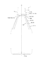
- the vertical direction is based on the upright state of the double container 1, and the upper direction means the upper side in FIG. 2 and the lower side means the lower side in FIG.
- the double container 1 includes a cylindrical mouth portion 11, and an upper portion having a conical shape continuous to the mouth portion 11 and a lower portion having a cylindrical shape. 12 and an outer layer body 10 in the form of a bottle having a bottom portion 13 having a substantially disk shape connected to the body portion 12.
- the trunk portion 12 has flexibility, can be squeezed and recessed, and can be restored from the recessed state to the original shape.
- the double container 1 is provided with an inner layer body (not shown), and the inner layer body has a shape corresponding to the shape of the outer layer body 10 and is configured to be capable of volumetric deformation.
- the inner layer body is formed in a bag shape thinner than the outer layer body 10, and its outer surface is in close contact with the inner surface of the outer layer body 10 in a peelable manner.
- the opening of the inner layer body is connected to the opening end of the mouth portion 11 of the outer layer body 10, and the inside of the inner layer body is a housing portion that is continuous to the opening.
- cosmetics such as lotion, shampoo, rinse, liquid soap, and liquid contents such as food seasonings are stored in the storage unit.
- the double container 1 is formed by coextruding a synthetic resin for the outer layer having low compatibility and a synthetic resin for the inner layer to form a laminated parison, and this laminated parison is blow-molded using a mold.
- a delamination container called a delamination container formed in a laminated structure in which the inner layer body is detachably adhered to the inner surface of the outer layer body 10.
- the double container 1 is not limited to such direct blow molding (extrusion blow molding: Blow molding), but is a laminate release container formed by, for example, biaxial stretching blow molding of a preform having a laminated structure. You may comprise as.
- the double container 1 may be a double container 1 having a configuration in which the outer layer body 10 and the inner layer body are separately formed and then the inner layer body is incorporated into the outer layer body 10.
- a pouring cap such as a pouring cap provided with a pouring valve, various nozzles, or a pouring pump is attached to the mouth portion 11 by a stopper, and through these pouring tools, The contents are poured out.
- a double container 1 is equipped with a pouring cap in which a pouring valve is arranged in the mouth portion 11, the contents from the mouth portion 11 can be obtained by squeezing the body portion 12 of the outer layer body 10. Things can be poured out.
- the outer layer body 10 is restored to its original shape after the contents are poured out, since the outside air flows between the outer layer body 10 and the inner layer body through an air introduction hole 11b described later, The outer layer body 10 can be restored to its original shape while the volume is reduced.
- the mouth part 11 is provided with a locking projection 11a as a stopper for stoppering for attaching the pouring tool to the mouth part 11 by undercut engagement with the stopper.
- the locking protrusion 11a can lock the pouring tool to the mouth portion 11 by undercut engagement with a locking groove provided on the inner peripheral surface of the pouring tool mounting cylinder.
- the locking projections 11a have a pair of arcs having intermittent portions at two locations facing each other across the central axis O of the double container 1 that coincides with the central axis of the mouth portion 11 in plan view.
- Circular air introduction holes 11b are provided at two locations facing the axis O slightly below the intermittent portion of the locking projection 11a in the mouth portion 11 of the outer layer body 10.
- the pair of air introduction holes 11b penetrates the outer layer body 10 and communicates between the outer layer body 10 and the inner layer body, and can introduce air when the inner layer body peels from the outer layer body 10. .
- a stepped portion 11c that is bent so that the peripheral wall forming the mouth portion 11 expands downward is provided below the air introduction hole 11b in the mouth portion 11.
- the step portion 11c allows the introduction of outside air into the air introduction hole 11b, while the mouth portion 11 is equipped with a pouring tool including an outside air introduction valve that prevents leakage of air from the air introduction hole 11b. It is possible to prevent air from leaking out from the lower end of the mounting cylinder by being in close contact with the lower end of the mounting cylinder of the dispensing tool.
- a neck ring 11 d is provided below the step portion 11 c in the mouth portion 11.
- the neck ring 11d is arranged with an interval in the circumferential direction, and the diameter of the neck ring 11d is increased by bending the circumferential wall forming the mouth portion 11 so as to protrude radially outward (see FIG. 5B).
- a ring enlarged portion 11d1 is provided. Between these ring enlarged diameter portions 11d1, four ring intermittent portions 11d2 that are smaller in diameter than the ring enlarged diameter portions 11d1 are arranged.
- the four ring intermittent portions 11d2 include two first ring intermittent portions 11d21 positioned immediately below the two air introduction holes 11b and two second ring intermittent portions positioned between the first ring intermittent portions 11d21 in the circumferential direction. Part 11d22.
- the first ring intermittent portion 11d21 is formed by bending the peripheral wall forming the mouth portion 11 so as to form a V-shaped longitudinal section.
- the second ring intermittent portion 11d22 is formed by bending the peripheral wall forming the mouth portion 11 so as to form a V-shaped cross section.
- a pair of rib groups 14 ⁇ / b> A corresponding to the pair of air introduction holes 11 b is formed on the upper portion of the trunk portion 12.
- Each of the pair of rib groups 14 ⁇ / b> A includes four ribs 14 that extend radially in the direction from the mouth portion 11 toward the bottom portion 13.
- the four ribs 14 include two enlarged-diameter portion ribs 14a in which an upper end 14a1 is arranged immediately below the ring enlarged-diameter portion 11d1, and two intermittent-part ribs 14b in which an upper end 14b1 is arranged directly under the first ring intermittent portion 11d21. It is made up of.
- the intermittent rib 14b includes an extended portion 14b2 that extends upward from the upper end 14a1 of the enlarged-diameter rib 14a.
- the four ribs 14 form concave grooves that are recessed inward in the radial direction. Further, the depth of the concave groove formed by the extension 14b2 is shallower than the portion immediately below the extension 14b2. Furthermore, the upper end of the extension part 14 b 2, that is, the upper end 14 b 1 of the intermittent part rib 14 b extends to the lower part of the mouth part 11. That is, the neck ring 11 d is provided above the lower end portion of the mouth portion 11, and the extension portion 14 b 2 extends beyond the lower end portion of the mouth portion 11.
- the first ring intermittent portion 11d21 is disposed directly below the air introduction hole 11b, and the upper end 14b1 of the extension portion 14b2 of the intermittent portion rib 14b is disposed directly below the first ring intermittent portion 11d21. 14 and the gap maintained around the inner layer rib can be connected to the air introduction hole 11b.
- the inner layer body is contracted by negative pressure suction so that the entire inner layer body is separated from the outer layer body 10, and then air is fed into the inner layer body 10. While maintaining gaps between the ribs 14 and the ribs of the inner layer body and between the first ring intermittent portion 11d21 of the outer layer body 10 and the first ring intermittent portion of the inner layer body, other portions of the inner layer body are used as the outer layer body. 10 can be brought into close contact with the inner surface.
- the gap around the first ring intermittent portion 11d21 and the rib 14 becomes a ventilation path, and the air introduction hole
- the outside air flowing in from 11b can easily flow into the space between the outer layer body 10 and the inner layer body on the bottom 13 side of the trunk portion 12.
- the mouth portion 11 is hardly stretched at the time of blow molding, the mouth portion 11 is formed thicker than the body portion 12. Therefore, in the mouth portion 11 having such a thick wall, it is more difficult to secure the airway than the trunk portion 12, but as described above, by extending the extension portion 14b2 beyond the lower end portion of the mouth portion 11, It is possible to secure the air passage more reliably.
- the double container 1 with the neck ring 11d
- the neck ring 11d is provided with a ring intermittent part 11d2 in which the diameter expansion is suppressed as compared with the ring widened part 11d1, so that the ring intermittent part 11d2 functions as a column part, so The buckling strength of the neck ring 11d can be improved. Therefore, according to the double container 1, it is possible to realize stabilization of the pouring operation of the pouring tool with respect to the mouth portion 11.
- the double container 1 includes a cylindrical mouth portion 11, a trunk portion 12 that is continuous with the mouth portion 11 and has a diameter larger than that of the mouth portion 11, and the trunk portion 12.
- a bottle-shaped outer layer body 10 having a bottom portion 13, and an inner layer body accommodated inside the outer layer body 10 and having a shape corresponding to the shape of the outer layer body 10 and capable of volumetric deformation.
- the part 11 has a configuration in which at least one air introduction hole 11b that penetrates the outer layer body 10 and introduces air between the outer layer body 10 and the inner layer body is provided.
- the double container 1 is provided in the mouth portion 11, and a stopper portion for locking (locking protrusion 11 a) for attaching the pouring tool to the mouth portion 11 with a stopper is provided around the mouth portion 11.
- the neck ring 11d and a plurality of ribs 14 provided at least on the upper portion of the body portion 12 and extending in the direction from the mouth portion 11 toward the bottom portion 13 are provided.
- the double container 1 includes at least one ring diameter-increased part 11d1 whose neck ring 11d has a diameter expanded by bending so that the peripheral wall forming the mouth part 11 is convex radially outward, and at least one
- the plurality of ribs 14 include at least one ring enlarged portion 11d1 that is adjacent to the ring enlarged portion 11d1 in the circumferential direction and includes at least one ring intermittent portion 11d2 that is smaller in diameter than the ring enlarged portion 11d1.
- At least one enlarged-diameter portion rib 14a having an upper end 14a1 disposed immediately below it and at least one of the upper end 14b1 disposed immediately below at least one ring intermittent portion 11d2 positioned immediately below at least one air introduction hole 11b. And at least one intermittent rib 14b is located above the upper end of at least one enlarged diameter rib 14a. It has a configuration that includes a prolonged extension 14b2.
- the double container 1 it is possible to both secure a sufficient airway from the air introduction hole 11b and stabilize the pouring operation of the extraction tool with respect to the mouth portion 11. it can.
- the neck ring 11d is provided above the lower end portion of the mouth portion 11, and the extension portion 14b2 extends beyond the lower end portion of the mouth portion 11. It is configured to be.
- a pair of air introduction holes 11b are provided in the mouth portion 11, and a pair of ring intermittent portions 11d2 and a pair of rib groups 14A are provided corresponding to the air introduction holes 11b.
- the air introduction hole 11b, the ring intermittent portion 11d2, and the rib group 14A are not limited to two, and one or three or more may be provided. Further, the number of ribs 14 included in the rib group 14A can be changed as appropriate.
- the rib 14 should just be provided in the upper part of the trunk
- a double container as an embodiment having the configuration shown in FIGS. 1 to 5 was manufactured, the strength of the neck ring was measured, and the fitting of the dispensing cap by plugging was performed. We confirmed whether it was possible. In addition, it was confirmed whether or not a sufficient airway was secured by pouring the contents from the attached pouring cap and examining whether or not the body portion was restored smoothly.
- a double container having the structure shown in FIGS. 6 (a) to 6 (c) was manufactured. Confirmation of adequacy and good airway maintenance.
- the neck ring does not have an intermittent portion, and the upper ends of the four ribs have the same height in Comparative Example 1 in FIG.
- the strength of the was insufficient, and the pouring cap could not be plugged into the mouth. For this reason, it was impossible to confirm the favorable airway securing.
- the comparative example 2 in FIG. 6B in which the intermittent portion of the neck ring is not located immediately below the air introduction hole and the upper ends of the four ribs are all the same height, However, the airway was not adequately secured.
- the stopper can also be plugged in Comparative Example 3 in FIG. 6C where the upper ends of the four ribs are all the same height.
- the intermittent portion of the neck ring is disposed immediately below the air introduction hole, and the upper end of the extended portion of the rib is disposed directly below the intermittent portion, so that it is sufficiently It was confirmed that both a secure airway can be achieved.
Landscapes
- Engineering & Computer Science (AREA)
- Mechanical Engineering (AREA)
- Ceramic Engineering (AREA)
- Containers Having Bodies Formed In One Piece (AREA)
- Containers And Packaging Bodies Having A Special Means To Remove Contents (AREA)
- Closures For Containers (AREA)
Abstract
Description
1.筒状をなす口部、該口部に連なると共に該口部よりも拡径した胴部、及び該胴部に連なる底部を有するボトル状をなす外層体と、該外層体の内側に収容され、該外層体の形状に対応した形状を有すると共に減容変形可能な内層体とを備え、前記口部に、前記外層体を貫通すると共に前記外層体と前記内層体との間に空気を導入する少なくとも1つの空気導入孔が設けられた二重容器において、
前記口部に設けられ、該口部に注出具を打栓によって装着させるための打栓用係止部と、
前記口部に周設されたネックリングと、
少なくとも前記胴部の上部に設けられ、前記口部から前記底部に向かう方向に延びる複数のリブとを備え、
前記ネックリングは、前記口部を形成する周壁が径方向外側に凸となるように屈曲することで拡径した少なくとも1つのリング拡径部と、前記少なくとも1つのリング拡径部に周方向に隣接すると共に該リング拡径部よりも拡径を抑えた少なくとも1つのリング間欠部とを備え、
前記複数のリブは、前記少なくとも1つのリング拡径部の直下に上端が配置された少なくとも1つの拡径部リブと、前記少なくとも1つの空気導入孔の直下に位置する前記少なくとも1つのリング間欠部の直下に上端が配置された少なくとも1つの間欠部リブとを備え、
前記少なくとも1つの間欠部リブは、前記少なくとも1つの拡径部リブの上端よりも上方に延長された延長部を備えることを特徴とする二重容器。
前記延長部は、前記口部の下端部を越えて延在している、前記1に記載の二重容器。
なお、本明細書において、上下方向とは、二重容器1の正立状態を基準とし、上方とは図2における上方、下方とは図2における下方を意味するものとする。

10 外層体
11 口部
11a 係止突起(打栓用係止部)
11b 空気導入孔
11c 段差部
11d ネックリング
11d1 リング拡径部
11d2 リング間欠部
11d21 第1リング間欠部
11d22 第2リング間欠部
12 胴部
13 底部
14 リブ
14A リブ群
14a 拡径部リブ
14a1 拡径部リブの上端
14b 間欠部リブ
14b1 間欠部リブの上端
14b2 延長部
O 軸線
Claims (2)
- 筒状をなす口部、該口部に連なると共に該口部よりも拡径した胴部、及び該胴部に連なる底部を有するボトル状をなす外層体と、該外層体の内側に収容され、該外層体の形状に対応した形状を有すると共に減容変形可能な内層体とを備え、前記口部に、前記外層体を貫通すると共に前記外層体と前記内層体との間に空気を導入する少なくとも1つの空気導入孔が設けられた二重容器において、
前記口部に設けられ、該口部に注出具を打栓によって装着させるための打栓用係止部と、
前記口部に周設されたネックリングと、
少なくとも前記胴部の上部に設けられ、前記口部から前記底部に向かう方向に延びる複数のリブとを備え、
前記ネックリングは、前記口部を形成する周壁が径方向外側に凸となるように屈曲することで拡径した少なくとも1つのリング拡径部と、前記少なくとも1つのリング拡径部に周方向に隣接すると共に該リング拡径部よりも拡径を抑えた少なくとも1つのリング間欠部とを備え、
前記複数のリブは、前記少なくとも1つのリング拡径部の直下に上端が配置された少なくとも1つの拡径部リブと、前記少なくとも1つの空気導入孔の直下に位置する前記少なくとも1つのリング間欠部の直下に上端が配置された少なくとも1つの間欠部リブとを備え、
前記少なくとも1つの間欠部リブは、前記少なくとも1つの拡径部リブの上端よりも上方に延長された延長部を備えることを特徴とする二重容器。 - 前記ネックリングは前記口部の下端部よりも上方に設けられており、
前記延長部は、前記口部の下端部を越えて延在している、請求項1に記載の二重容器。
Priority Applications (5)
| Application Number | Priority Date | Filing Date | Title |
|---|---|---|---|
| CN201680074924.3A CN108367834B (zh) | 2015-12-25 | 2016-11-15 | 双层容器 |
| EP16878206.8A EP3395704B8 (en) | 2015-12-25 | 2016-11-15 | Double-walled container |
| KR1020187017339A KR102076923B1 (ko) | 2015-12-25 | 2016-11-15 | 이중 용기 |
| CA3009031A CA3009031C (en) | 2015-12-25 | 2016-11-15 | Double-walled container |
| US16/063,613 US10597187B2 (en) | 2015-12-25 | 2016-11-15 | Doubled-walled container |
Applications Claiming Priority (2)
| Application Number | Priority Date | Filing Date | Title |
|---|---|---|---|
| JP2015255229A JP6594771B2 (ja) | 2015-12-25 | 2015-12-25 | 二重容器 |
| JP2015-255229 | 2015-12-25 |
Publications (1)
| Publication Number | Publication Date |
|---|---|
| WO2017110310A1 true WO2017110310A1 (ja) | 2017-06-29 |
Family
ID=59090064
Family Applications (1)
| Application Number | Title | Priority Date | Filing Date |
|---|---|---|---|
| PCT/JP2016/083838 WO2017110310A1 (ja) | 2015-12-25 | 2016-11-15 | 二重容器 |
Country Status (7)
| Country | Link |
|---|---|
| US (1) | US10597187B2 (ja) |
| EP (1) | EP3395704B8 (ja) |
| JP (1) | JP6594771B2 (ja) |
| KR (1) | KR102076923B1 (ja) |
| CN (1) | CN108367834B (ja) |
| CA (1) | CA3009031C (ja) |
| WO (1) | WO2017110310A1 (ja) |
Families Citing this family (19)
| Publication number | Priority date | Publication date | Assignee | Title |
|---|---|---|---|---|
| JP6906844B2 (ja) * | 2017-04-28 | 2021-07-21 | 株式会社吉野工業所 | 積層剥離容器 |
| JP7382698B2 (ja) * | 2017-09-28 | 2023-11-17 | 株式会社吉野工業所 | 吐出容器 |
| JP7142423B2 (ja) * | 2017-09-29 | 2022-09-27 | 株式会社吉野工業所 | 積層剥離容器 |
| JP7098229B2 (ja) * | 2017-10-31 | 2022-07-11 | 株式会社吉野工業所 | 二重容器 |
| WO2019087515A1 (ja) * | 2017-10-31 | 2019-05-09 | 株式会社吉野工業所 | 二重容器 |
| JP7090977B2 (ja) * | 2017-11-30 | 2022-06-27 | 株式会社吉野工業所 | 積層剥離容器 |
| EP3733539A4 (en) | 2017-12-28 | 2021-11-03 | Yoshino Kogyosho Co., Ltd. | RESIN CONTAINER |
| JP7094620B2 (ja) * | 2018-01-31 | 2022-07-04 | 株式会社吉野工業所 | 合成樹脂製容器 |
| CN116280581A (zh) * | 2018-05-28 | 2023-06-23 | 京洛株式会社 | 容器 |
| JP7235947B2 (ja) * | 2018-05-28 | 2023-03-09 | キョーラク株式会社 | 積層剥離容器 |
| JP7161101B2 (ja) * | 2018-09-28 | 2022-10-26 | キョーラク株式会社 | 積層剥離容器 |
| CN112041234B (zh) * | 2018-05-28 | 2023-06-02 | 京洛株式会社 | 容器 |
| JP7139057B2 (ja) * | 2018-09-28 | 2022-09-20 | 株式会社吉野工業所 | 積層剥離容器 |
| JP7072999B2 (ja) * | 2018-11-30 | 2022-05-23 | 株式会社吉野工業所 | 合成樹脂製容器、及び合成樹脂製容器の製造方法 |
| JP7309266B2 (ja) * | 2019-01-31 | 2023-07-18 | 株式会社吉野工業所 | 二重容器 |
| JP7204303B2 (ja) * | 2019-05-29 | 2023-01-16 | 株式会社吉野工業所 | 二重容器及びその製造方法 |
| JP7403294B2 (ja) * | 2019-11-29 | 2023-12-22 | 株式会社吉野工業所 | 押出しブロー容器 |
| CN111806831B (zh) * | 2020-07-17 | 2022-04-12 | 广州华研精密机械股份有限公司 | 防光照的阻隔容器胚体及阻隔容器 |
| DE102021114558A1 (de) | 2021-06-07 | 2022-12-08 | Khs Gmbh | Vorformling aus thermoplastischem Material zur Herstellung eines Behälters |
Citations (4)
| Publication number | Priority date | Publication date | Assignee | Title |
|---|---|---|---|---|
| EP0403259A1 (en) * | 1989-06-13 | 1990-12-19 | Mcg Industries (Pty) Limited | Capping and de-capping of plastic bottles |
| JP2003192031A (ja) * | 2001-12-21 | 2003-07-09 | Kao Corp | 積層剥離容器 |
| JP2012076758A (ja) * | 2010-09-30 | 2012-04-19 | Yoshino Kogyosho Co Ltd | キャップ付き容器 |
| JP2014091537A (ja) * | 2012-10-31 | 2014-05-19 | Yoshino Kogyosho Co Ltd | 積層剥離容器 |
Family Cites Families (23)
| Publication number | Priority date | Publication date | Assignee | Title |
|---|---|---|---|---|
| US2808167A (en) * | 1955-02-01 | 1957-10-01 | Polazzolo Samuel | Thermos insulated container for baby bottle |
| US3513531A (en) * | 1967-11-30 | 1970-05-26 | Union Carbide Corp | Method of making vacuum containers |
| US4372455A (en) * | 1980-01-18 | 1983-02-08 | National Can Corporation | Thin walled plastic container construction |
| US4330066A (en) * | 1980-11-21 | 1982-05-18 | Robert Berliner | Receptacle with collapsible internal container |
| JPH0813499B2 (ja) * | 1987-03-04 | 1996-02-14 | 三菱瓦斯化学株式会社 | 多層容器及びその製造法 |
| US4892230A (en) * | 1988-02-08 | 1990-01-09 | Lynn Jr Arthur E | Carbonated beverage bottle |
| CA2113117C (en) * | 1992-05-11 | 2005-10-11 | Tsutomu Kobayashi | Laminated bottle and pump device therefor |
| JP3268087B2 (ja) * | 1993-09-30 | 2002-03-25 | 株式会社吉野工業所 | プラスチックボトル |
| EP0759399B1 (en) * | 1995-03-10 | 2002-01-09 | Yoshino Kogyosho Co., Ltd. | Punching method for laminated container |
| JP3464405B2 (ja) * | 1999-02-18 | 2003-11-10 | 阪神化成工業株式会社 | 多層薄肉容器 |
| US6670007B1 (en) * | 1999-04-07 | 2003-12-30 | Owens-Brockway Plastic Products Inc. | Multilayer container |
| AU2002343802B2 (en) * | 2001-10-31 | 2007-11-22 | Yoshino Kogyosho Co., Ltd. | Blow-molded container |
| US7055707B2 (en) * | 2001-10-31 | 2006-06-06 | Yoshino Kogyosho Co., Ltd. | Peelably laminated blow-molded containers |
| US20070051687A1 (en) * | 2005-09-07 | 2007-03-08 | Omnitech International, Inc | Reclosable metal bottle |
| JP4846428B2 (ja) | 2006-04-25 | 2011-12-28 | 株式会社吉野工業所 | 積層剥離ボトル |
| JP5267901B2 (ja) * | 2007-06-29 | 2013-08-21 | 株式会社吉野工業所 | ダイレクトブロー成形法による合成樹脂製二重容器 |
| JP2009102074A (ja) * | 2008-11-26 | 2009-05-14 | Japan Crown Cork Co Ltd | 容器本体と容器蓋間の洗浄方法 |
| WO2012118527A1 (en) * | 2011-03-01 | 2012-09-07 | Advanced Technology Materials, Inc. | Nested blow molded liner and overpack and methods of making same |
| JP5917368B2 (ja) * | 2012-10-31 | 2016-05-11 | 株式会社吉野工業所 | 二重容器 |
| KR101673830B1 (ko) * | 2012-10-31 | 2016-11-07 | 가부시키가이샤 요시노 고교쇼 | 이중 용기 |
| JP2014091581A (ja) * | 2013-12-18 | 2014-05-19 | Yoshino Kogyosho Co Ltd | 積層剥離容器 |
| EP3088325B1 (en) * | 2013-12-27 | 2018-11-21 | Kao Corporation | Squeeze container |
| JP6396192B2 (ja) * | 2014-11-28 | 2018-09-26 | 株式会社吉野工業所 | 二重容器 |
-
2015
- 2015-12-25 JP JP2015255229A patent/JP6594771B2/ja active Active
-
2016
- 2016-11-15 CA CA3009031A patent/CA3009031C/en active Active
- 2016-11-15 KR KR1020187017339A patent/KR102076923B1/ko active IP Right Grant
- 2016-11-15 EP EP16878206.8A patent/EP3395704B8/en active Active
- 2016-11-15 CN CN201680074924.3A patent/CN108367834B/zh active Active
- 2016-11-15 WO PCT/JP2016/083838 patent/WO2017110310A1/ja active Application Filing
- 2016-11-15 US US16/063,613 patent/US10597187B2/en active Active
Patent Citations (4)
| Publication number | Priority date | Publication date | Assignee | Title |
|---|---|---|---|---|
| EP0403259A1 (en) * | 1989-06-13 | 1990-12-19 | Mcg Industries (Pty) Limited | Capping and de-capping of plastic bottles |
| JP2003192031A (ja) * | 2001-12-21 | 2003-07-09 | Kao Corp | 積層剥離容器 |
| JP2012076758A (ja) * | 2010-09-30 | 2012-04-19 | Yoshino Kogyosho Co Ltd | キャップ付き容器 |
| JP2014091537A (ja) * | 2012-10-31 | 2014-05-19 | Yoshino Kogyosho Co Ltd | 積層剥離容器 |
Also Published As
| Publication number | Publication date |
|---|---|
| JP2017114555A (ja) | 2017-06-29 |
| KR20180087303A (ko) | 2018-08-01 |
| EP3395704B8 (en) | 2020-08-19 |
| EP3395704A4 (en) | 2019-08-28 |
| KR102076923B1 (ko) | 2020-02-12 |
| JP6594771B2 (ja) | 2019-10-23 |
| CA3009031A1 (en) | 2017-06-29 |
| CN108367834B (zh) | 2019-10-01 |
| CN108367834A (zh) | 2018-08-03 |
| EP3395704B1 (en) | 2020-07-15 |
| EP3395704A1 (en) | 2018-10-31 |
| US20180370671A1 (en) | 2018-12-27 |
| US10597187B2 (en) | 2020-03-24 |
| CA3009031C (en) | 2019-08-20 |
Similar Documents
| Publication | Publication Date | Title |
|---|---|---|
| WO2017110310A1 (ja) | 二重容器 | |
| JP6730095B2 (ja) | 二重容器 | |
| JP6906844B2 (ja) | 積層剥離容器 | |
| US20150298890A1 (en) | Double container | |
| JP7098229B2 (ja) | 二重容器 | |
| JP6054706B2 (ja) | 積層剥離容器 | |
| JP7199781B2 (ja) | 積層剥離容器 | |
| JP2019210003A (ja) | 積層剥離容器 | |
| JP2020193021A (ja) | 二重容器及びその製造方法 | |
| JP2020121778A (ja) | 二重容器 | |
| JP6808379B2 (ja) | 積層剥離容器 | |
| JP2018090282A (ja) | 二重容器 | |
| WO2019087515A1 (ja) | 二重容器 | |
| JP7098232B2 (ja) | 積層剥離容器 | |
| JP6173892B2 (ja) | 二重容器 | |
| JP6366519B2 (ja) | 二重容器 | |
| JP2020001802A (ja) | スクイズ容器 | |
| JP5937022B2 (ja) | 二重容器 | |
| JP6910715B2 (ja) | 二重容器、注出具付き容器及びプリフォーム | |
| JP6957087B2 (ja) | 積層剥離容器 | |
| JP7399557B2 (ja) | 二重容器及び二重容器の製造方法 | |
| JP2018016401A (ja) | 二重容器 | |
| JP2023111718A (ja) | 積層剥離容器 |
Legal Events
| Date | Code | Title | Description |
|---|---|---|---|
| 121 | Ep: the epo has been informed by wipo that ep was designated in this application |
Ref document number: 16878206 Country of ref document: EP Kind code of ref document: A1 |
|
| ENP | Entry into the national phase |
Ref document number: 3009031 Country of ref document: CA |
|
| ENP | Entry into the national phase |
Ref document number: 20187017339 Country of ref document: KR Kind code of ref document: A |
|
| WWE | Wipo information: entry into national phase |
Ref document number: 1020187017339 Country of ref document: KR |
|
| NENP | Non-entry into the national phase |
Ref country code: DE |
|
| WWE | Wipo information: entry into national phase |
Ref document number: 2016878206 Country of ref document: EP |
|
| ENP | Entry into the national phase |
Ref document number: 2016878206 Country of ref document: EP Effective date: 20180725 |