WO2017094316A1 - 運転支援装置 - Google Patents
運転支援装置 Download PDFInfo
- Publication number
- WO2017094316A1 WO2017094316A1 PCT/JP2016/076885 JP2016076885W WO2017094316A1 WO 2017094316 A1 WO2017094316 A1 WO 2017094316A1 JP 2016076885 W JP2016076885 W JP 2016076885W WO 2017094316 A1 WO2017094316 A1 WO 2017094316A1
- Authority
- WO
- WIPO (PCT)
- Prior art keywords
- vehicle
- driver
- lane change
- lane
- unit
- Prior art date
- Legal status (The legal status is an assumption and is not a legal conclusion. Google has not performed a legal analysis and makes no representation as to the accuracy of the status listed.)
- Ceased
Links
Images

Classifications
-
- G—PHYSICS
- G06—COMPUTING OR CALCULATING; COUNTING
- G06V—IMAGE OR VIDEO RECOGNITION OR UNDERSTANDING
- G06V20/00—Scenes; Scene-specific elements
- G06V20/50—Context or environment of the image
- G06V20/59—Context or environment of the image inside of a vehicle, e.g. relating to seat occupancy, driver state or inner lighting conditions
- G06V20/597—Recognising the driver's state or behaviour, e.g. attention or drowsiness
-
- B—PERFORMING OPERATIONS; TRANSPORTING
- B60—VEHICLES IN GENERAL
- B60W—CONJOINT CONTROL OF VEHICLE SUB-UNITS OF DIFFERENT TYPE OR DIFFERENT FUNCTION; CONTROL SYSTEMS SPECIALLY ADAPTED FOR HYBRID VEHICLES; ROAD VEHICLE DRIVE CONTROL SYSTEMS FOR PURPOSES NOT RELATED TO THE CONTROL OF A PARTICULAR SUB-UNIT
- B60W30/00—Purposes of road vehicle drive control systems not related to the control of a particular sub-unit, e.g. of systems using conjoint control of vehicle sub-units
- B60W30/18—Propelling the vehicle
- B60W30/18009—Propelling the vehicle related to particular drive situations
- B60W30/18163—Lane change; Overtaking manoeuvres
-
- B—PERFORMING OPERATIONS; TRANSPORTING
- B60—VEHICLES IN GENERAL
- B60R—VEHICLES, VEHICLE FITTINGS, OR VEHICLE PARTS, NOT OTHERWISE PROVIDED FOR
- B60R21/00—Arrangements or fittings on vehicles for protecting or preventing injuries to occupants or pedestrians in case of accidents or other traffic risks
-
- B—PERFORMING OPERATIONS; TRANSPORTING
- B60—VEHICLES IN GENERAL
- B60W—CONJOINT CONTROL OF VEHICLE SUB-UNITS OF DIFFERENT TYPE OR DIFFERENT FUNCTION; CONTROL SYSTEMS SPECIALLY ADAPTED FOR HYBRID VEHICLES; ROAD VEHICLE DRIVE CONTROL SYSTEMS FOR PURPOSES NOT RELATED TO THE CONTROL OF A PARTICULAR SUB-UNIT
- B60W30/00—Purposes of road vehicle drive control systems not related to the control of a particular sub-unit, e.g. of systems using conjoint control of vehicle sub-units
- B60W30/14—Adaptive cruise control
-
- B—PERFORMING OPERATIONS; TRANSPORTING
- B60—VEHICLES IN GENERAL
- B60W—CONJOINT CONTROL OF VEHICLE SUB-UNITS OF DIFFERENT TYPE OR DIFFERENT FUNCTION; CONTROL SYSTEMS SPECIALLY ADAPTED FOR HYBRID VEHICLES; ROAD VEHICLE DRIVE CONTROL SYSTEMS FOR PURPOSES NOT RELATED TO THE CONTROL OF A PARTICULAR SUB-UNIT
- B60W40/00—Estimation or calculation of non-directly measurable driving parameters for road vehicle drive control systems not related to the control of a particular sub unit, e.g. by using mathematical models
- B60W40/08—Estimation or calculation of non-directly measurable driving parameters for road vehicle drive control systems not related to the control of a particular sub unit, e.g. by using mathematical models related to drivers or passengers
-
- B—PERFORMING OPERATIONS; TRANSPORTING
- B60—VEHICLES IN GENERAL
- B60W—CONJOINT CONTROL OF VEHICLE SUB-UNITS OF DIFFERENT TYPE OR DIFFERENT FUNCTION; CONTROL SYSTEMS SPECIALLY ADAPTED FOR HYBRID VEHICLES; ROAD VEHICLE DRIVE CONTROL SYSTEMS FOR PURPOSES NOT RELATED TO THE CONTROL OF A PARTICULAR SUB-UNIT
- B60W50/00—Details of control systems for road vehicle drive control not related to the control of a particular sub-unit, e.g. process diagnostic or vehicle driver interfaces
- B60W50/08—Interaction between the driver and the control system
- B60W50/10—Interpretation of driver requests or demands
-
- B—PERFORMING OPERATIONS; TRANSPORTING
- B60—VEHICLES IN GENERAL
- B60W—CONJOINT CONTROL OF VEHICLE SUB-UNITS OF DIFFERENT TYPE OR DIFFERENT FUNCTION; CONTROL SYSTEMS SPECIALLY ADAPTED FOR HYBRID VEHICLES; ROAD VEHICLE DRIVE CONTROL SYSTEMS FOR PURPOSES NOT RELATED TO THE CONTROL OF A PARTICULAR SUB-UNIT
- B60W50/00—Details of control systems for road vehicle drive control not related to the control of a particular sub-unit, e.g. process diagnostic or vehicle driver interfaces
- B60W50/08—Interaction between the driver and the control system
- B60W50/12—Limiting control by the driver depending on vehicle state, e.g. interlocking means for the control input for preventing unsafe operation
-
- B—PERFORMING OPERATIONS; TRANSPORTING
- B60—VEHICLES IN GENERAL
- B60W—CONJOINT CONTROL OF VEHICLE SUB-UNITS OF DIFFERENT TYPE OR DIFFERENT FUNCTION; CONTROL SYSTEMS SPECIALLY ADAPTED FOR HYBRID VEHICLES; ROAD VEHICLE DRIVE CONTROL SYSTEMS FOR PURPOSES NOT RELATED TO THE CONTROL OF A PARTICULAR SUB-UNIT
- B60W50/00—Details of control systems for road vehicle drive control not related to the control of a particular sub-unit, e.g. process diagnostic or vehicle driver interfaces
- B60W50/08—Interaction between the driver and the control system
- B60W50/14—Means for informing the driver, warning the driver or prompting a driver intervention
-
- G—PHYSICS
- G08—SIGNALLING
- G08G—TRAFFIC CONTROL SYSTEMS
- G08G1/00—Traffic control systems for road vehicles
- G08G1/16—Anti-collision systems
- G08G1/166—Anti-collision systems for active traffic, e.g. moving vehicles, pedestrians, bikes
-
- G—PHYSICS
- G08—SIGNALLING
- G08G—TRAFFIC CONTROL SYSTEMS
- G08G1/00—Traffic control systems for road vehicles
- G08G1/16—Anti-collision systems
- G08G1/167—Driving aids for lane monitoring, lane changing, e.g. blind spot detection
-
- B—PERFORMING OPERATIONS; TRANSPORTING
- B60—VEHICLES IN GENERAL
- B60W—CONJOINT CONTROL OF VEHICLE SUB-UNITS OF DIFFERENT TYPE OR DIFFERENT FUNCTION; CONTROL SYSTEMS SPECIALLY ADAPTED FOR HYBRID VEHICLES; ROAD VEHICLE DRIVE CONTROL SYSTEMS FOR PURPOSES NOT RELATED TO THE CONTROL OF A PARTICULAR SUB-UNIT
- B60W2420/00—Indexing codes relating to the type of sensors based on the principle of their operation
- B60W2420/40—Photo, light or radio wave sensitive means, e.g. infrared sensors
- B60W2420/403—Image sensing, e.g. optical camera
-
- B—PERFORMING OPERATIONS; TRANSPORTING
- B60—VEHICLES IN GENERAL
- B60W—CONJOINT CONTROL OF VEHICLE SUB-UNITS OF DIFFERENT TYPE OR DIFFERENT FUNCTION; CONTROL SYSTEMS SPECIALLY ADAPTED FOR HYBRID VEHICLES; ROAD VEHICLE DRIVE CONTROL SYSTEMS FOR PURPOSES NOT RELATED TO THE CONTROL OF A PARTICULAR SUB-UNIT
- B60W2540/00—Input parameters relating to occupants
Definitions
- the present disclosure relates to a driving support device that supports driving of a driver.
- Patent Literature 1 discloses a technique for automatically changing a vehicle to an adjacent lane by operating a driver's blinker lever.
- the target vehicle When the target vehicle is automatically changed to the adjacent lane, the rear side vehicle traveling in the adjacent lane is monitored by the target vehicle's autonomous sensor to ensure the rear side safety on the target vehicle system side. It is also possible to change lanes automatically. However, at present, it is not preferable to overtrust the vehicle system due to the limit of the detection range of the autonomous sensor, and it is preferable that the driver confirms the safety.
- An object of the present disclosure is to provide a driving support device that can prompt the driver to perform safety confirmation even when the vehicle lane is automatically changed.
- the driving support device is provided in a vehicle and includes a lane change unit that automatically changes the lane of the vehicle. Furthermore, an operation determination unit and a change permission unit are provided.
- the operation determination unit determines whether or not the driver has performed a safety confirmation operation when changing lanes based on information of a sensor used to detect the state of the driver of the vehicle.
- the change permission section permits automatic lane changes by the lane change section, and if the operation determination section determines that the driver has not performed a safety check operation at the time of lane change, the lane change section automatically Do not allow any lane changes.
- the permission unit does not permit the lane change by the lane change unit automatically. Therefore, when the lane change of the vehicle is automatically performed, the lane change cannot be performed unless the driver performs a safety confirmation operation at the time of the lane change. Therefore, even when the lane change of the vehicle is automatically performed, the driver performs a safety confirmation operation when changing the lane.
- a driving assistance system 1 shown in FIG. 1 is mounted on a vehicle, and includes ADAS (Advanced Driver Assistance Systems) locator 2, ITS (Intelligent Transport Systems) communication device 3, peripheral monitoring system 4, HMI (Human Machine Interface).
- ADAS Advanced Driver Assistance Systems
- ITS Intelligent Transport Systems
- peripheral monitoring system 4 HMI (Human Machine Interface).
- a system 5 a vehicle control system 6, a winker lever 7, a winker switch 8, and a driving support ECU 9 are included.
- the ADAS locator 2, the ITS communicator 3, the periphery monitoring system 4, the HMI system 5, the vehicle control system 6, the blinker switch 8, and the driving support ECU 9 are connected to, for example, the in-vehicle LAN 10 and exchange information with each other by communication. Can do.
- a vehicle equipped with the driving support system 1 is referred to as a host vehicle or a subject vehicle.
- the ADAS locator 2 includes a GNSS receiver, an inertial sensor such as a 3D gyro sensor, and a memory for storing map data.
- a GNSS (Global Navigation Satellite System) receiver receives positioning signals from a plurality of artificial satellites.
- the 3D gyro sensor includes, for example, a triaxial gyro sensor and a triaxial acceleration sensor.
- the ADAS locator 2 measures the position of the vehicle by combining the positioning signal received by the GNSS receiver and the measurement result of the inertial sensor.
- the ADAS locator 2 reads out map data ahead of the course of the vehicle from the memory, and extracts road information such as road shape, number of lanes, lane width, lane restriction information, speed restriction value, and intersection point position.
- the ADAS locator 2 outputs the position information of the own vehicle and the road information ahead of the course to the in-vehicle LAN 10.
- “Information” is used not only as a countable noun but also as a countable noun, and is equivalent to an information item.
- One information item is equivalent to one information item, and a plurality of information items are equivalent to a plurality of information items.
- the road information may be obtained by using an in-vehicle communication module used for telematics communication such as DCM (Data Communication Module) mounted on the vehicle.
- DCM Data Communication Module
- the ITS communication device 3 performs wireless communication with an in-vehicle communication device installed in a surrounding vehicle of the own vehicle and / or a roadside device installed on the roadside. For example, the ITS communication device 3 acquires the position information, the traveling speed information, and the like of the surrounding vehicle of the host vehicle through vehicle-to-vehicle communication with the in-vehicle communication device and road-to-vehicle communication with the roadside device. The ITS communication device 3 outputs the acquired information to the in-vehicle LAN 10.
- the periphery monitoring system 4 includes a periphery monitoring sensor such as a periphery monitoring camera 41 and a millimeter wave radar 42, and a periphery monitoring ECU 40.
- the perimeter monitoring system 4 may be configured to use a perimeter monitoring sensor such as sonar, LIDAR (Light Detection, and Ranging / Laser Imaging, Detection, Detection, and Ranging).
- LIDAR Light Detection, and Ranging / Laser Imaging, Detection, Detection, and Ranging
- the surrounding monitoring system 4 detects obstacles such as moving objects such as pedestrians, animals other than humans, bicycles, motorcycles, and other vehicles, and falling objects on the road, guardrails, curbs, and stationary objects such as trees.
- a travel lane line is detected, a traffic light color, a road sign, and a road sign display are detected.
- the HMI system 5 includes a plurality of display devices such as a combination meter 53, a CID (Center Information Display) 54, a HUD (Head-Up Display) device 55, and an electronic mirror 56.
- the HMI system 5 further includes a DSM (Driver Status Monitor) 51, a rear side camera 52, an audio speaker 57, and an operation device 58.
- the HMI system 5 receives an input operation from the driver of the own vehicle, presents information to the driver of the own vehicle, and monitors the state of the driver of the own vehicle.
- the vehicle control system 6 includes an accelerator position sensor 61, a brake pedal force sensor 62, a steering angle sensor 63, a steering torque sensor 64, and other detection sensors that detect driving operations, a vehicle speed sensor 65 that detects the traveling state of the host vehicle, and the like. It has.
- the vehicle control system 6 includes an electronic control throttle 66, a brake actuator 67, a travel control device such as an EPS (Electric Power Steering) motor 68, and a vehicle control ECU 60.
- the vehicle control system 6 controls the traveling of the host vehicle based on a driving operation by the driver, an instruction from the driving support ECU 9, and the like.
- the winker lever 7 is an operation member for performing a lamp lighting operation of the direction indicator of the own vehicle.
- the blinker lever 7 corresponds to a predetermined operation member.
- the blinker switch 8 is a switch for detecting left and right lamp lighting operations on the blinker lever 7.
- the blinker switch 8 outputs a blinker signal for turning left or right according to the operation of the blinker lever 7 to the in-vehicle LAN 10.
- the driving support ECU 9 includes a volatile memory, a non-volatile memory, an I / O, and a bus connecting these, and executes various processes by executing a control program stored in the non-volatile memory.
- the driving support ECU 9 corresponds to a driving support device. Note that some or all of the functions executed by the driving support ECU 9 may be configured in hardware by one or a plurality of ICs.
- the driving support ECU 9 controls the vehicle control ECU 60 to execute a plurality of driving support applications (hereinafter referred to as driving support apps) that perform driving operation support or substitutes by the driver.
- driving support apps a plurality of driving support applications
- the periphery monitoring system 4 includes a periphery monitoring ECU 40, a periphery monitoring camera 41, and a millimeter wave radar 42.
- the periphery monitoring camera 41 is a monocular or compound eye camera, and sequentially captures the periphery of the vehicle.
- a front camera is provided as the periphery monitoring camera 41 will be described as an example.
- the periphery monitoring camera 41 is installed in, for example, a rearview mirror of the own vehicle with the optical axis directed toward the road surface in front of the own vehicle.
- the peripheral monitoring camera 41 images a range of about 80 meters from the own vehicle with a horizontal viewing angle of about 45 degrees, for example. Then, the periphery monitoring camera 41 sequentially outputs captured image data to be sequentially captured to the periphery monitoring ECU 40.
- the millimeter wave radar 42 sequentially transmits millimeter waves or quasi-millimeter waves around the vehicle and sequentially receives the reflected waves reflected by the obstacles.
- a right rear side millimeter wave radar whose sensing range is the right rear side from the right side of the own vehicle to the rear side and a left rear side from the left side of the own vehicle to the rear side are the sensing range.
- a case where the left rear side millimeter wave radar is provided will be described as an example.
- a configuration using a millimeter wave radar 42 having another sensing range such as a millimeter wave radar 42 having a sensing range in front of the host vehicle may be used.
- the right rear side millimeter wave radar is installed on the right side of the rear part of the vehicle. Then, a quasi-millimeter wave in the 24 GHz band is emitted in a range of about 120 degrees in the horizontal scanning angle from the rear of the vehicle to the right rear side, and the reflected wave is received.
- the left rear side millimeter wave radar is the same as the right rear side millimeter wave radar except that the left and right sides are reversed.
- the maximum detection distance of the millimeter wave radar 42 is about 70 to 150 m. Then, the millimeter wave radar 42 sequentially outputs the scanning result based on the received signal to the periphery monitoring ECU 40.
- the periphery monitoring ECU 40 includes a CPU, a volatile memory, a nonvolatile memory, an I / O, and a bus connecting them, and executes various processes by executing a control program stored in the nonvolatile memory. Note that some or all of the functions executed by the periphery monitoring ECU 40 may be configured in hardware by one or a plurality of ICs.
- the periphery monitoring ECU 40 detects the distance from the own vehicle, the relative position with respect to the own vehicle, the relative speed with respect to the own vehicle, and the like of the object existing in front of the own vehicle from the data of the captured image acquired from the periphery monitoring camera 41.
- a vehicle such as an automobile, a bicycle, or a motorcycle, a pedestrian, or the like may be detected by a known image recognition process such as template matching.
- the relative position of the object relative to the own vehicle, the own vehicle and the object are determined from the installation position of the periphery monitoring camera 41 with respect to the own vehicle, the direction of the optical axis, and the position of the object in the captured image. Can be determined.
- the distance between the vehicle and the object may be determined based on the parallax amount of the pair of cameras.
- the relative speed of the object with respect to the own vehicle may be determined from the rate of change of the inter-vehicle distance between the own vehicle and the object. For example, if the detected object is a vehicle and the relative position to the host vehicle is in front of the host vehicle, this object may be treated as a preceding vehicle.
- the periphery monitoring ECU 40 detects the travel lane line in the traveling direction of the host vehicle, the position of the travel lane line relative to the host vehicle, and the like from the captured image data acquired from the periphery monitoring camera 41.
- the travel lane marking may be detected by a known image recognition process such as edge detection. What is necessary is just to detect the position of the lane marking with respect to the own vehicle from the installation position of the periphery monitoring camera 41 with respect to the own vehicle, the direction of the optical axis, and the position of the object in the captured image.
- the periphery monitoring ECU 40 may be configured to detect a signboard indicating lane restrictions, a road installation indicating lane restrictions, and the like by image recognition processing.
- the surrounding monitoring ECU 40 detects the distance from the own vehicle, the relative position with respect to the own vehicle, the relative speed with respect to the own vehicle, and the like of the object existing behind the own vehicle from the information acquired from the millimeter wave radar 42. .
- the periphery monitoring ECU 40 detects the object based on the reception intensity of the reflected wave generated by the quasi-millimeter wave transmitted from the millimeter wave radar 42 being reflected on the object. Further, the periphery monitoring ECU 40 detects the distance between the vehicle and the object from the time from when the quasi-millimeter wave is transmitted until the reflected wave is received. Further, the periphery monitoring ECU 40 detects the direction of the object with respect to the own vehicle from the direction in which the quasi-millimeter wave from which the reflected wave is obtained is transmitted. Then, the relative position of the object with respect to the own vehicle is detected from the distance between the own vehicle and the object and the direction of the object with respect to the own vehicle.
- the periphery monitoring ECU 40 detects the relative speed of the object with respect to the own vehicle by a known method based on the Doppler shift between the transmitted quasi-millimeter wave and the reflected wave. In addition, you may detect the relative speed of the object with respect to the own vehicle from the time change rate of the distance of the own vehicle and an object.
- the periphery monitoring ECU 40 outputs various types of detected information to the in-vehicle LAN 10 as monitoring information.
- the surrounding monitoring ECU 40 may detect the presence of the surrounding vehicle, the distance from the own vehicle, the position and the speed with respect to the own vehicle using the position information and traveling speed information of the surrounding vehicle acquired from the ITS communication device 3. Good.
- the number, type, and combination of types of the peripheral monitoring sensors included in the peripheral monitoring system 4 are not limited to the examples shown in the first embodiment.
- it may be configured to have a sensing range in which a plurality of types of surrounding monitoring sensors overlap, such as performing sensing in front of the host vehicle in combination with a camera and a millimeter wave radar.
- a surrounding monitoring sensor it is further equipped with a millimeter-wave radar that has a sensing range in the left and right diagonal front of the vehicle, and a sonar that has a sensing range in the vicinity of the left and right front corners and the left and right rear corners of the vehicle. It is good also as composition to do.
- the HMI system 5 includes an HCU (Human Machine Interface Control Unit) 50, a DSM 51, a rear side camera 52, a combination meter 53, a CID 54, a HUD device 55, an electronic mirror 56, an audio speaker 57, and an operation device 58.
- HCU Human Machine Interface Control Unit
- the DSM 51 includes a near-infrared light source and a near-infrared camera, and a control unit that controls them.
- the DSM 51 is disposed, for example, on the upper surface of the instrument panel in a posture in which the near-infrared camera faces the driver's seat side of the own vehicle.
- the DSM 51 images the driver's head irradiated with near-infrared light from a near-infrared light source with a near-infrared camera.
- the image captured by the near-infrared camera is analyzed by the control unit.
- the control unit detects, for example, the driver's face direction and / or line-of-sight direction from the captured image.
- This DSM 51 corresponds to a sensor.
- the DSM 51 detects parts such as a face outline, eyes, nose, and mouth by image recognition processing from a captured image obtained by capturing the driver's face with a near-infrared camera. Then, the face orientation of the driver is detected from the relative positional relationship of each part. Also, as an example, the DSM 51 detects the driver's pupil and corneal reflection from the captured image obtained by capturing the driver's face with a near-infrared camera, and recognizes the line of sight from the positional relationship between the detected pupil and corneal reflection. Detect the direction of. The DSM 51 outputs information on the detected driver's face direction and line-of-sight direction to the in-vehicle LAN 10.
- parts such as a face outline, eyes, nose, and mouth by image recognition processing from a captured image obtained by capturing the driver's face with a near-infrared camera. Then, the face orientation of the driver is detected from the relative positional relationship of each part.
- the DSM 51 detects the driver's
- the DSM 51 may be configured to detect the face orientation by using the distance between the driver's head or shoulder and the driver's seat or headrest depending on the driver's face orientation.
- the DSM 51 may be configured to detect the face orientation from changes in the distance to the head or shoulders of the driver, which are detected by a plurality of distance measuring sensors installed on the driver's seat or the headrest, respectively.
- the rear side camera 52 is, for example, a monocular camera, and sequentially images the rear side of the vehicle.
- the rear side cameras 52 are respectively installed on the left and right door mirrors of the own vehicle, and respectively image predetermined ranges on the left and right rear sides of the own vehicle.
- the rear side camera 52 sequentially outputs captured image data to be sequentially captured to the HCU 50.
- the combination meter 53 is arranged in front of the driver's seat in the passenger compartment of the own vehicle.
- the CID 54 is arranged above the center cluster in the passenger compartment of the host vehicle.
- the combination meter 53 and the CID 54 display various images for information notification on the display screen based on the image data acquired from the HCU 50.
- the HUD device 55 projects the display image formed on the display element based on the image data acquired from the HCU 50 onto the windshield of the host vehicle, thereby converting the virtual image of the display image from Overlapping display is possible.
- the HUD device 55 presents information to the driver by a display object displayed as a virtual image.
- the electronic mirror 56 is a display device that sequentially displays captured images of the rear side of the host vehicle sequentially captured by the rear side camera 52, and a display device that displays a captured image of the right rear side of the host vehicle, There is a display device that displays a captured image of the left rear side of the vehicle.
- the electronic mirror 56 is installed at the base of each pillar located on the left and right sides of the windshield in the vehicle interior of the host vehicle. The electronic mirror 56 sequentially acquires and displays captured images captured sequentially by the rear side camera 52 via the HCU 50.
- the electronic mirror 56 may superimpose the display object generated by the HCU 50 in addition to the captured image of the rear side of the vehicle taken by the rear side camera 52. Further, the display area of the display object generated by the HCU 50 and the rear side captured image captured by the rear side camera 52 may be displayed separately. The electronic mirror 56 presents information to the driver by a display object displayed in addition to the captured image of the rear side of the host vehicle.
- the audio speaker 57 is installed, for example, in the lining of the door of the own vehicle, and reproduces sound or sound that can be heard by the driver of the own vehicle. Specifically, synthesized beeps such as mechanical beeps and messages are output from the audio speaker 57. The audio speaker 57 presents information to the driver by using sound and voice to be reproduced.
- the operation device 58 is a group of switches operated by the driver of the own vehicle.
- the operation device 58 there is a steering switch provided in a spoke spoke portion of the own vehicle.
- the steering switch is used for the driver to make various settings including the necessity of starting the driving support application, or for the driver to permit automatic lane change.
- the HCU 50 includes a CPU, a volatile memory, a non-volatile memory, an I / O, and a bus connecting them, and executes various processes by executing a control program stored in the non-volatile memory. Note that some or all of the functions executed by the HCU 50 may be configured in hardware by one or a plurality of ICs.
- the HCU 50 provides information to the driver by controlling the combination meter 53, the CID 54, the HUD device 55, the electronic mirror 56, and the audio speaker 57 to present information. Further, the HCU 30 sequentially outputs captured image data of the rear side of the own vehicle sequentially acquired from the rear side camera 52 to the electronic mirror 56. In addition, the HCU 50 outputs a signal corresponding to the detection result of the DSM 51 and the switch operation of the operation device 58 to the in-vehicle LAN 10.
- the vehicle control system 6 includes a vehicle control ECU 60, an accelerator position sensor 61, a brake pedal force sensor 62, a steering angle sensor 63, a steering torque sensor 64, a vehicle speed sensor 65, an electronic control throttle 66, a brake actuator 67, and an EPS motor 68. Yes.
- the accelerator position sensor 61 detects the amount of depression of the accelerator pedal by the driver and outputs it to the vehicle control ECU 60.
- the brake pedaling force sensor 62 detects the pedaling force of the brake pedal by the driver and outputs it to the vehicle control ECU 60.
- the steering angle sensor 63 detects the steering angle or the turning angle of the host vehicle as the steering angle.
- the steering torque sensor 64 detects the steering torque applied to the steering wheel by the driver and outputs it to the vehicle control ECU 60.
- the vehicle speed sensor 65 detects the current traveling speed of the host vehicle by measuring the output shaft of the transmission or the rotational speed of the axle, and outputs it to the vehicle control ECU 60.
- the electronic control throttle 66 controls the opening of the throttle based on a control signal output from the vehicle control ECU 60.
- the brake actuator 67 controls the braking force generated on each wheel by generating a brake pressure based on a control signal output from the vehicle control ECU 60.
- the EPS motor 68 controls the steering force and the steering force applied to the steering mechanism based on the control signal output from the vehicle control ECU 60.
- the vehicle control ECU 60 is an electronic control device that performs acceleration / deceleration control and / or steering control of the host vehicle.
- the vehicle control ECU 60 includes a steering ECU that performs steering control, a power unit control ECU that performs acceleration / deceleration control, a brake ECU, and the like.
- the vehicle control ECU 60 uses an electronic control throttle 66, a brake actuator 67, and an EPS motor based on detection signals output from sensors such as an accelerator position sensor 61, a brake pedal force sensor 62, a rudder angle sensor 63, and a vehicle speed sensor 65.
- a control signal is output to each traveling control device such as 68.
- the vehicle control ECU 60 performs acceleration / deceleration control and / or steering control of the host vehicle in accordance with an instruction from the drive support ECU 9 when the drive support application is executed.
- the vehicle control ECU 60 also outputs detection signals output from the sensors 61 to 65 to the in-vehicle LAN 10.
- the driving assistance ECU 9 executes a control program stored in the non-volatile memory, whereby an LCA (Lane Change Assist) function unit 90, an ACC (Adaptive Cruise Control) function unit 91, an LKA (Lane Keeping Assist) function unit 92, And AEB (Autonomous Emergency Braking) function unit 93 is constructed as a function block. With these functional blocks, the above-described driving support application is executed.
- LCA Local Area Change Assist
- ACC Adaptive Cruise Control
- LKA Lane Keeping Assist
- AEB Automatic Emergency Braking
- the ACC function unit 91 realizes an ACC function of controlling the traveling speed of the host vehicle by causing the vehicle control ECU 60 to adjust the driving force and the braking force based on the monitoring information of the preceding vehicle acquired from the surrounding monitoring ECU 40.
- the ACC function unit 91 causes the host vehicle to travel at a constant speed, for example, at a target travel speed set by the driver via the operation device 58.
- the ACC function unit 91 sets the target inter-vehicle distance to the preceding vehicle according to the target traveling speed with the speed of the preceding vehicle as the target traveling speed.
- the host vehicle is caused to follow the preceding vehicle while performing acceleration / deceleration control so as to be the target inter-vehicle distance.
- the speed of the preceding vehicle may be obtained from the relative speed of the preceding vehicle with respect to the own vehicle detected by the surrounding monitoring ECU 40 and the vehicle speed indicated by the detection signal of the vehicle speed sensor 65 of the own vehicle.
- the LKA function unit 92 realizes the LKA function of controlling the steering angle of the steering wheel of the host vehicle by causing the vehicle control ECU 60 to adjust the steering force.
- the LKA function unit 92 maintains the host vehicle in the host lane by generating a steering force in a direction that prevents the approach to the travel lane line.
- the driving support that activates both the ACC function and the LKA function to realize automatic driving in the traveling lane of the own vehicle is hereinafter referred to as in-lane driving support.
- the AEB function unit 93 causes the vehicle control ECU 60 to adjust the braking force on the basis of the monitoring information in front of the host vehicle acquired from the surrounding monitoring ECU 40, thereby forcibly reducing the vehicle speed of the host vehicle. That is, the AEB function is realized.
- TTC time-to-collision
- the vehicle speed of the host vehicle is forcibly automatically decelerated.
- the LCA function unit 90 realizes an LCA function for moving the vehicle from the currently traveling lane to the adjacent lane. Details of the LCA function unit 90 will be described later.
- the driving assistance ECU 9 is configured to notify the driver of the presence of other vehicles in the left and right rear side areas of the own vehicle based on the monitoring information on the left and right rear sides of the own vehicle acquired from the surrounding monitoring ECU 40. It is good also as a structure which implement
- the LCA function unit 90 includes, as function blocks, a state transition unit 100, an LC (Lane Change) intention determination unit 101, an intention detection unit 102, an operation determination unit 103, a timeout determination unit 104, a surrounding state determination unit 105, a permission unit 106, Promotion processing unit 107, lane change unit 108, and post-completion processing unit 109 (state transition unit 100, LC (Lane Change) intention determination unit 101, intention detection unit 102, operation determination unit 103, timeout determination unit 104, surrounding situation determination Device 105, permission device 106, acceleration processor 107, lane change device 108, and post-completion processor 109).
- state transition unit 100 state transition unit 100, an LC (Lane Change) intention determination unit 101, intention detection unit 102, operation determination unit 103, timeout determination unit 104, surrounding situation determination Device 105, permission device 106, acceleration processor 107, lane change device 108, and post-completion processor 109.
- the state transition unit 100 transitions the state of the LCA function of the own vehicle.
- the state transition unit 100 sets the LC_OFF state in which the LCA function cannot be executed, for example, when the in-lane travel support is OFF (that is, both the functions of ACC and LKA are inactive).
- it is set as LC_OFF when the surrounding monitoring ECU 40 cannot detect the adjacent lane of the own vehicle.
- the case where the adjacent lane of the own vehicle cannot be detected refers to the case where the travel lane between the own lane and the adjacent lane cannot be detected.
- the state transition unit 100 performs LCA. Transition to the LC_READY state where the function is ready to be executed.
- the state transition unit 100 determines that the driver's intention to change the lane is determined by the later-described LC intention determination unit 101
- the state transition unit 100 causes the LCA function unit 90 to transition to the LC_ON state in which the LCA function is executed.
- the state transition unit 100 transitions to the LC_READY state when the timeout determination unit 104 described later determines that the determination result of the LC intention determination unit 101 or the operation determination unit 103 is invalid.
- the state transition unit 100 transitions to the LC_READY state when steering in the lane change unit 108 described later is completed.
- LC intention determination unit 101 determines the driver's intention to change lanes when in the LC_READY state. As an example, when a winker signal at the time of turning left or right is obtained from the winker switch 8, it may be determined that there is an intention to change lanes (hereinafter, there is an LC intention). Further, when a winker signal for a right turn is obtained, it is determined that the right adjacent lane has an LC intention, and when a winker signal for a left turn is obtained, it is determined that the left adjacent lane has an LC intention. If the blinker signal at the time of turning left or right is not obtained, it may be determined that there is no LC intention. In the first embodiment, the blinker lever 7 corresponds to an operation member.
- the intention detection unit 102 starts counting from the time point when the LC intention determination unit 101 determines that there is an LC intention. That is, the count starting from the time when the blinker lever 7 is operated is started. Then, it is detected that the driver has permitted the lane change (hereinafter referred to as steering start trigger ON) that the count has reached the specified value.
- the count may be a count of elapsed time or a count of the travel distance of the own vehicle, but the following description will be given by taking an example of counting the elapsed time.
- the elapsed time may be counted by, for example, a timer circuit. This count corresponds to the measured value.
- the operation determination unit 103 determines whether or not the driver has performed a safety confirmation operation when changing lanes based on the detection results of the DSM 51 sequentially output from the HCU 50.
- the determination by the operation determination unit 103 is preferably started after the LC intention determination unit 101 determines that there is an LC intention. This is because the processing load of the driving assistance ECU 9 can be reduced as compared with the configuration in which the determination by the operation determination unit 103 is always performed.
- the fixed time is a residence time that is considered to be normally required for safety confirmation, and can be arbitrarily set.
- the line-of-sight direction when detecting to the driver's line-of-sight direction with the DSM 51, for example, when the line-of-sight direction moves in the order of the front of the vehicle, the right door mirror, the right rear side, and the front, it is determined that the safety confirmation operation has been performed. May be. For the right door mirror and the right rear side, the line-of-sight direction may stay for a certain time or longer.
- the intention to change the lane to the right adjacent lane is excluded except that the left and right are reversed. This is the same as when it is determined that there is.
- the timeout determination unit 104 determines whether the detection result of the intention detection unit 102 and the determination result of the operation determination unit 103 have expired (that is, timed out).
- the detection result of the intention detection unit 102 is determined to be a timeout when the elapsed time from the detection of the steering start trigger ON by the intention detection unit 102 is equal to or longer than the first effective time, and valid when the time is less than the first effective time. Is determined.
- the first valid time mentioned here can be arbitrarily set and may be about several seconds.
- the elapsed time after determining that the safety determination operation has been performed in the operation determination unit 103 is equal to or longer than the second effective time, it is determined as a timeout, and is less than the second effective time. If it is determined to be valid.
- the second valid time referred to here is a time at which it is considered highly likely that the situation on the rear side of the adjacent lane will change, and can be arbitrarily set. For example, the second valid time may be about several seconds.
- the surrounding situation determination unit 105 determines whether or not the surrounding situation of the host vehicle is a surrounding situation in which the lane can be changed to an adjacent lane based on the monitoring information sequentially output from the surrounding monitoring ECU 40 in the LC_ON state. Judge sequentially. As an example, if there is no object approaching the host vehicle in the rear side of the lane to which the lane is changed from the monitoring information on the rear side of the host vehicle detected by the millimeter wave radar 42, the surrounding situation in which the lane can be changed Is determined. On the other hand, if there is an object approaching the host vehicle on the rear side of the lane to which the lane is changed, it is determined that the lane change is impossible.
- the surrounding situation determination unit 105 determines whether there is another vehicle approaching the host vehicle behind the lane to which the lane is changed, based on the position information and traveling speed information of the surrounding vehicle acquired by the ITS communication device 3. By determining whether or not, it may be determined whether or not the surrounding situation of the host vehicle is a surrounding situation where the lane can be changed to an adjacent lane.
- the permission unit 106 is also referred to as a change permission unit and a change permission device, and when the state becomes LC_ON, the lane change of the own vehicle is permitted or not permitted depending on whether or not a predetermined condition is satisfied.
- the predetermined condition is that the intention detection unit 102 detects that the steering start trigger is ON, the operation determination unit 103 determines that the safety check operation has been performed, and the surrounding state determination unit 105 determines that the surrounding situation is lane changeable. This means that the determination result of the LC intention determination unit 101 and the operation determination unit 103 is not determined to be timeout by the timeout determination unit 104.
- the specified value here is a value that can be arbitrarily set corresponding to a time shorter than the first effective time described above, and may be, for example, 3 seconds.
- the promotion processing unit 107 outputs, to the HCU 50, an instruction for instructing the driver to perform the safety confirmation operation based on the fact that the operation determination unit 103 determines that the safety confirmation operation is not performed.
- the driver is notified of the safety confirmation operation. It is sufficient to adopt a configuration that allows
- the certain time mentioned here can be set arbitrarily, and may be set in consideration of the time required for a driver with a slow safety check operation such as the elderly to complete the safety check operation.
- the HCU 50 that has received the instruction to perform the notification causes the display device and the audio speaker 57 to notify the driver of the safety confirmation operation.
- a configuration for performing a safety confirmation operation on a display device such as the electronic mirror 56 may be displayed, or a configuration such as simply turning on a lamp such as an LED may be used.
- the lane change unit 108 instructs the vehicle control ECU 60 to move the host vehicle to the adjacent lane by generating a steering force in the direction toward the adjacent lane.
- the post-completion processing unit 109 performs post-steering completion processing when steering in the process of moving the host vehicle to the adjacent lane in the lane change unit 108 is completed.
- an instruction to perform notification indicating that the lane change has been completed is output to the HCU 50, and notification indicating that the lane change has been completed is performed from the display device or the audio speaker 57.
- the display indicating that the lane is being changed may be terminated by the post-steering completion processing.
- an instruction may be output to the electronic control device that operates the winker lever, and the winker lever 7 operated by the driver may be automatically returned to the neutral position.
- LCA related processing an example of the flow of processing related to the LCA function in the driving support ECU 9 (hereinafter, LCA related processing) will be described using the flowchart of FIG. 3
- the flowchart of FIG. 3 may be configured to start, for example, when the driving assistance in the lane in the driving assistance ECU 9 is ON (that is, both the functions of ACC and LKA are activated).
- the described flowchart includes a plurality of sections (or referred to as steps), and each section is expressed as, for example, S1. Further, each section can be divided into a plurality of subsections, while a plurality of sections can be combined into one section.
- Each section can be referred to as a device, or as a proper name, and with structural modifiers, for example, a motion determination section, as a motion determination device, a motion determiner.
- the section includes (i) not only a section of software combined with a hardware unit (eg, a computer) but also (ii) a section of hardware (eg, an integrated circuit, a wiring logic circuit) and related devices. It can be realized with or without the function.
- the hardware section can be included inside the microcomputer.
- an instruction to perform notification indicating that the operation of the winker lever 7 and the safety confirmation operation are necessary is output to the HCU 50, and the display device and the audio speaker 57 are used. This notification is preferably performed. If it is determined in S7 and S8 that a time-out has occurred, the winker lever 7 that has been operated by the driver is automatically returned to the neutral position, so that the operation of the winker lever 7 and the safety confirmation operation are required again. It is good also as a structure which makes a driver recognize.
- the lane changing unit 108 instructs the vehicle control ECU 60 to move the host vehicle to the adjacent lane.
- the process proceeds to S11.
- the post-completion processing unit 109 performs post-steering post-processing, and the process proceeds to S12.
- the LCA related process is ended if it is the end timing of the LCA related process (YES in S14). On the other hand, if it is not the end timing of the LCA related process (NO in S14), the process returns to S1 and the process is repeated.
- the LCA function unit 90 sets the LC_OFF state in at least one of the case where the in-lane driving support is OFF and the case where the surrounding monitoring ECU 40 cannot detect the adjacent lane of the own vehicle. Become.
- the in-lane travel support is ON in the LC_OFF state and the adjacent monitoring lane of the host vehicle can be detected by the surrounding monitoring ECU 40, the state transitions from the LC_OFF to the LC_READY state.
- the state transits to the LC_ON state.
- the timeout determination unit 104 determines that a timeout has occurred, the state transitions to the LC_READY state.
- the three conditions such as the surrounding situation in which the lane can be changed, the detection of the steering start trigger ON, and the execution of the safety confirmation operation are satisfied, the lane change is permitted and the steering is started. The Then, when the steering is completed and the post-steering completion process is executed and the lane change is completed, the state transitions from the LC_ON state to the LC_READY state.
- the permission unit 106 automatically performs the lane change unit 108. Do not allow any lane changes. Therefore, even when the lane change of the vehicle is automatically performed by the LCA function, the driver has to perform a safety confirmation operation at the time of the lane change. Further, since the lane change cannot be performed unless the driver performs the safety confirmation operation when changing the lane, the driver can be prompted to perform the safety confirmation operation. As a result, it is possible to make the driver a habit of confirming safety when changing lanes, and to promote the growth of the driver.
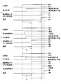
- the driver performs the safety confirmation operation as an indispensable condition for lane change permission. By doing so, it is possible to personally adapt the steering start timing at the time of lane change. Details will be described below with reference to FIG.
- FIG. 5A shows an example in which the safety confirmation operation by the driver is not an essential condition for permission to change lanes.
- B and C of FIG. 5 have shown the example in case implementation of the safety confirmation operation
- FIG. 5B shows an example of a driver whose operation from the operation of the blinker lever 7 to the execution of the safety confirmation operation is early, and FIG. An example is shown.
- the prescribed value (A Need to be set larger.
- the execution of the safety confirmation operation by the driver is an indispensable condition for permitting the lane change.
- the specified count value (see T1 of B and C) can be set smaller than the case of A. Therefore, if the driver is quick from the operation of the blinker lever 7 to the safety confirmation operation, the steering can be started earlier than in the case of A by the amount that the specified count value can be set smaller (T1 of B). reference).
- T1 of B the amount that the specified count value can be set smaller
- the steering is not started until the safety confirmation operation is performed (see T2 of C). .
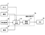
- the driving support ECU 9a is the same as the driving support ECU 9 of the first embodiment except that the driving support ECU 9a includes a scene determination unit 110 and a proposal processing unit 111 (also referred to as a scene determination unit 110 and a proposal processing unit 111).
- the scene determination unit 110 and the proposal processing unit 111 may be configured to be included in the LCA function unit 90, or may be configured not to be included in the LCA function unit 90.
- the scene determination unit 110 determines whether the lane change is a preferable driving scene based on the traveling state of the own vehicle and / or the situation around the own vehicle.
- the scene determination unit 110 is a driving scene in which the lane change is preferable based on the position of the own vehicle and the position of the crossing point acquired from the ADAS locator 2 and the inter-vehicle distance between the own vehicle and the preceding vehicle acquired from the surrounding monitoring ECU 40. It is determined whether it is. As a specific example, when the own vehicle is a predetermined distance or more away from the intersection and the distance between the own vehicle and the preceding vehicle is not more than a predetermined value, it may be determined that the lane change is a preferable driving scene. .
- the predetermined distance may be any distance as long as it is longer than the distance that should be prohibited from changing lanes before the crossing point.
- the predetermined value mentioned here may be approximately the target inter-vehicle distance when it can be said that the speed of the preceding vehicle is significantly lower than the speed regulation value, and can be arbitrarily set.
- the predetermined value may be sequentially changed according to the speed regulation value included in the map data acquired from the ADAS locator 2, or may be a fixed value regardless of the speed regulation value.
- the scene determination unit 110 determines whether the lane change of the own vehicle is a preferable driving scene based on the position of the own vehicle and the lane restriction information acquired from the ADAS locator 2. As a specific example, it may be determined that the lane change is a preferable driving scene when the own vehicle is less than a predetermined distance to a point where the lane must be changed due to lane restrictions.
- the predetermined distance here can be arbitrarily set.
- the lane restriction information regarding the point where the lane must be changed due to the lane restriction may be obtained from the roadside device via the ITS communication device 3.
- the driving support ECU 9 can acquire information on a planned route such as a recommended route that is being route-guided by the car navigation device and a planned route that is planned to be driven by automatic driving, the planned route is used. It is good also as a structure which determines the driving scene where a lane change is preferable in the scene determination part 110.
- FIG. As an example, when a right / left turn is necessary at an intersection ahead of the traveling direction from the planned route, and the lane change is necessary for the right / left turn, the scene determination unit 110 indicates that the lane change is a preferable driving scene. What is necessary is just to judge.
- the suggestion processing unit 111 When the scene determination unit 110 determines that the lane change is a preferable driving scene, the suggestion processing unit 111 outputs an instruction to the HCU 50 to notify the lane change of the own vehicle.
- the HCU 50 that has received the instruction to perform the notification causes the display device and the audio speaker 57 to perform notification for proposing the lane change of the own vehicle.
- the display device such as the electronic mirror 56 may be configured to display a text or icon that suggests a lane change.
- the determination by the operation determination unit 103 may be started.
- the timing at which it is determined that the safety confirmation operation has been performed may be earlier than in the case of the first embodiment.
- the valid time may be set longer than in the case of the first embodiment.
- the safety confirmation operation is performed before the operation of the blinker lever 7 when the lane is changed. It is also possible to determine the safety confirmation operation of the driver that implements the above. Therefore, it is possible to prevent a situation in which the lane change is not permitted if the safety confirmation operation is not performed even though the safety confirmation operation is performed before the operation of the blinker lever 7.
- the steering for changing the lane is not automatically started on the condition that only the elapsed time from the operation of the blinker lever 7 is used. Accordingly, there is no problem that the steering for automatically changing the lane is started before the driver who performs the safety confirmation operation after operating the blinker lever 7 completes the safety confirmation operation.
- the configuration in which the LCA-related processing is started when the in-lane travel support is turned on is shown, but the configuration is not necessarily limited thereto.
- it may be configured to start when the ACC function is activated without activating the LKA function, or when the vehicle is driven manually without activating the ACC function or the LKA function. It is good also as a structure.
- the intention detection unit 102 detects that the steering start trigger is ON, the operation determination unit 103 determines that the safety confirmation operation is performed, and the surrounding situation determination unit 105 can change the lane.
- the timeout determination unit 104 does not determine a timeout, it is not necessarily limited thereto.
- the intention detection unit 102 may detect the steering start trigger ON as a condition for not allowing the lane change.
- the intention detection unit 102 detects that the count starting from the time point when the LC intention determination unit 101 determines that there is an LC intention has reached a specified value as the steering start trigger ON.
- the configuration is shown, it is not necessarily limited to this.
- the operation device 58 may be configured to detect, as the steering start trigger ON, that the driver of the operation device 58 has operated a button or the like used to communicate the intention of changing the lane.
- the operation device 58 corresponds to an operation member.
- it may be configured to detect that the driver has operated the steering wheel as a steering start trigger ON.
- the steering wheel corresponds to the operation member.
- the intention detection unit 102 may detect that the driver has operated the steering wheel from the signal of the steering torque sensor 64.
- a configuration is shown in which the timeout determination unit 104 determines a timeout when the elapsed time after the intention detection unit 102 detects that the steering start trigger is ON is equal to or longer than the first effective time.
- the timeout determination unit 104 determines a timeout when the elapsed time after the intention detection unit 102 detects that the steering start trigger is ON is equal to or longer than the first effective time.
- this is not necessarily the case.
- a configuration may be adopted in which a time-out is determined when the elapsed time since the driver operated the blinker lever 7, that is, when the count in the intention detection unit 102 is equal to or longer than the first valid time.
- the first effective time may be set to a time longer than the time taken for the driver to operate the blinker lever 7 to complete the safety check. More preferably, the first valid time may be set longer with reference to a driver with a slow safety check so that a timeout is not determined during a safety check operation by a driver with a slow safety check. For example, the first valid time may be about 10 seconds.
- the timing at which the operation determination unit 103 determines whether the safety confirmation operation has been performed is not necessarily limited to the timing described in the first embodiment and the first modification.
- the promotion processing unit 107 performs a notification that prompts the driver to perform a safety confirmation operation based on the fact that the operation determination unit 103 determines that the safety confirmation operation is not performed.
- the present invention is not limited to this.
- it may be configured to notify the driver of the safety confirmation operation.
Landscapes
- Engineering & Computer Science (AREA)
- Automation & Control Theory (AREA)
- Mechanical Engineering (AREA)
- Transportation (AREA)
- Physics & Mathematics (AREA)
- General Physics & Mathematics (AREA)
- Human Computer Interaction (AREA)
- Multimedia (AREA)
- Theoretical Computer Science (AREA)
- Mathematical Physics (AREA)
- Traffic Control Systems (AREA)
- Control Of Driving Devices And Active Controlling Of Vehicle (AREA)
Abstract
運転支援装置(9)は、車両のドライバの状態を検出するのに用いるセンサの情報をもとに、ドライバが車線変更時における安全確認動作を実施したか否か判定する動作判定部(103)と、車線変更部(108)による自動での車線変更を許可する変更許可部(106)とを備え、変更許可部は、動作判定部でドライバが車線変更時における安全確認動作を実施していないと判定している場合には、車線変更部による自動での車線変更を許可しない。
Description
本出願は、2015年11月30日に出願された日本出願番号2015-232879号に基づくもので、ここにその記載内容を援用する。
本開示は、ドライバの運転を支援する運転支援装置に関するものである。
従来、ドライバの運転を支援する技術が知られている。例えば、特許文献1には、ドライバのウィンカレバーの操作によって、隣接車線へ車両を自動で車線変更させる技術が開示されている。
しかしながら、特許文献1に開示の技術では、ドライバのウィンカレバーの操作を開始条件として、隣接車線へ車両を自動で車線変更させるので、ドライバが安全確認を行わなくても車線変更させてしまう。
隣接車線へ対象車を自動で車線変更させる場合、隣接車線を走行中の後側方車両を対象車の自律センサによって監視することで、対象車のシステム側で後側方の安全を確保して自動で車線変更することも考えられる。しかしながら、現状、自律センサの検知範囲の限界等から、車両のシステムを過信し過ぎるのは好ましくなく、ドライバが安全確認を行うことが好ましい。
本開示の目的は、自動で車両の車線変更を行わせる場合であっても、ドライバによる安全確認の実施を促すことができる運転支援装置を提供することにある。
上記目的を達成するために、本開示の一つの観点によれば、運転支援装置は、車両で用いられ、自動で車両の車線変更を行わせる車線変更部を備えるように提供される。さらに、動作判定部と、変更許可部とを備える。動作判定部は、車両のドライバの状態を検出するのに用いるセンサの情報をもとに、ドライバが車線変更時における安全確認動作を実施したか否か判定する。変更許可部は車線変更部による自動での車線変更を許可し、動作判定部でドライバが車線変更時における安全確認動作を実施していないと判定している場合には、車線変更部による自動での車線変更を許可しない。
これによれば、動作判定部でドライバが車線変更時における安全確認動作を実施していないと判定している場合には、許可部が、車線変更部による自動での車線変更を許可しない。よって、自動で車両の車線変更を行わせる場合に、ドライバが車線変更時における安全確認動作を実施しないと車線変更を行わせることができない。従って、自動で車両の車線変更を行わせる場合であっても、ドライバが車線変更時における安全確認動作を実施するようになる。
本開示についての上記目的およびその他の目的、特徴や利点は、添付の図面を参照しながら下記の詳細な記述により、より明確になる。
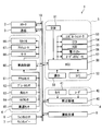
運転支援システムの概略的な構成の一例を示す図である。
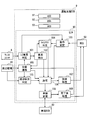
運転支援ECUの概略的な構成の一例を示す図である。
運転支援ECUでのLCA関連処理の流れの一例を示すフローチャートである。
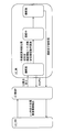
LCA機能部の状態遷移の一例について説明するための模式図である。
第1実施形態の構成による効果を説明するための図である。
第2実施形態の運転支援ECUの概略的な構成の一例を示す図である。
図面を参照しながら、開示のための複数の実施形態及び変形例を説明する。なお、説明の便宜上、複数の実施形態及び変形例の間において、それまでの説明に用いた図に示した部分と同一の機能を有する部分については、同一の符号を付し、その説明を省略する場合がある。同一の符号を付した部分については、他の実施形態及び/又は変形例における説明を参照することができる。
(第1実施形態)
<運転支援システム1の概略構成>
以下、本開示の第1実施形態について図面を用いて説明する。図1に示す運転支援システム1は、車両に搭載されるものであり、ADAS(Advanced Driver Assistance Systems)ロケータ2、ITS(Intelligent Transport Systems)通信機3、周辺監視システム4、HMI(Human Machine Interface)システム5、車両制御システム6、ウィンカレバー7、ウィンカスイッチ8、及び運転支援ECU9を含んでいる。ADASロケータ2、ITS通信機3、周辺監視システム4、HMIシステム5、車両制御システム6、ウィンカスイッチ8、及び運転支援ECU9は、例えば車内LAN10に接続されており、通信によって互いに情報をやり取りすることができる。運転支援システム1を搭載している車両を以降では自車(Host Vehicle)とあるいは対象車(Subject Vehicle)と呼ぶ。
<運転支援システム1の概略構成>
以下、本開示の第1実施形態について図面を用いて説明する。図1に示す運転支援システム1は、車両に搭載されるものであり、ADAS(Advanced Driver Assistance Systems)ロケータ2、ITS(Intelligent Transport Systems)通信機3、周辺監視システム4、HMI(Human Machine Interface)システム5、車両制御システム6、ウィンカレバー7、ウィンカスイッチ8、及び運転支援ECU9を含んでいる。ADASロケータ2、ITS通信機3、周辺監視システム4、HMIシステム5、車両制御システム6、ウィンカスイッチ8、及び運転支援ECU9は、例えば車内LAN10に接続されており、通信によって互いに情報をやり取りすることができる。運転支援システム1を搭載している車両を以降では自車(Host Vehicle)とあるいは対象車(Subject Vehicle)と呼ぶ。
ADASロケータ2は、GNSS受信機、3Dジャイロセンサ等の慣性センサ、地図データを格納するメモリを備えている。GNSS(Global Navigation Satellite System)受信機は、複数の人工衛星からの測位信号を受信する。3Dジャイロセンサは、例えば3軸ジャイロセンサ及び3軸加速度センサを備える。
ADASロケータ2は、GNSS受信機で受信する測位信号と、慣性センサの計測結果とを組み合わせることにより、自車の位置を測位する。ADASロケータ2は、メモリから自車の進路前方の地図データを読み出し、道路形状、車線数、車線幅、車線規制情報、速度規制値、交叉点位置等の道路情報を抽出する。ADASロケータ2は、自車の位置情報と、進路前方の道路情報とを、車内LAN10へ出力する。尚、「情報」は、不可算名詞のみならず、可算名詞としても使用され、情報項目と同等である。一つの情報は一つの情報項目と、複数の情報は、複数の情報項目と同等である。
なお、道路情報は、自車に搭載されたDCM(Data Communication Module)といったテレマティクス通信に用いられる車載通信モジュールを用いて取得する構成としてもよい。
ITS通信機3は、自車の周辺車両に搭載された車載通信機及び/又は路側に設置された路側機との間で、無線通信を行う。例えばITS通信機3は、車載通信機との車車間通信、路側機との路車間通信により、自車の周辺車両の位置情報及び走行速度情報等を取得する。ITS通信機3は、取得した情報を車内LAN10へ出力する。
周辺監視システム4は、周辺監視カメラ41、ミリ波レーダ42等の周辺監視センサと、周辺監視ECU40とを備えている。周辺監視システム4は、ソナー、LIDAR(Light Detection and Ranging/Laser Imaging Detect ion and Ranging)等の周辺監視センサを用いる構成としてもよい。周辺監視システム4は、歩行者、人間以外の動物、自転車、オートバイ、及び他車等の移動物体、さらに路上の落下物、ガードレール、縁石、及び樹木等の静止物体といった障害物を検出する。他にも、走行区画線を検出したり、交通信号の灯色、道路標示、道路標識の表示を検出したりする。
HMIシステム5は、コンビネーションメータ53、CID(Center Information Display)54、HUD(Head-Up Display)装置55、及び電子ミラー56等の複数の表示デバイスを備えている。さらにHMIシステム5は、DSM(Driver Status Monitor)51、後側方カメラ52、オーディオスピーカ57、及び操作デバイス58を備えている。HMIシステム5は、自車のドライバからの入力操作を受け付けたり、自車のドライバに向けて情報を提示したり、自車のドライバの状態を監視したりする。
車両制御システム6は、アクセルポジションセンサ61、ブレーキ踏力センサ62、舵角センサ63、及び操舵トルクセンサ64等の運転操作を検出する検出センサと、自車の走行状態を検出する車速センサ65等とを備えている。加えて車両制御システム6は、電子制御スロットル66、ブレーキアクチュエータ67、及びEPS(Electric Power Steering)モータ68等の走行制御デバイスと、車両制御ECU60とを備えている。車両制御システム6は、運転者による運転操作、運転支援ECU9からの指示等に基づいて、自車の走行を制御する。
ウィンカレバー7は、自車の方向指示器のランプ点灯操作を行うための操作部材である。第1実施形態では、このウィンカレバー7は所定の操作部材に相当する。ウィンカスイッチ8は、ウィンカレバー7に対する左右それぞれのランプ点灯操作を検出するためのスイッチである。ウィンカスイッチ8は、ウィンカレバー7の操作に応じた右左折時のウィンカ信号を車内LAN10へ出力する。
運転支援ECU9は、揮発性メモリ、不揮発性メモリ、I/O、これらを接続するバスを備え、不揮発性メモリに記憶された制御プログラムを実行することで各種の処理を実行する。この運転支援ECU9は運転支援装置に相当する。なお、運転支援ECU9が実行する機能の一部または全部を、一つあるいは複数のIC等によりハードウェア的に構成してもよい。
運転支援ECU9は、車両制御ECU60を制御することにより、ドライバによる運転操作の支援又は代行を行う複数の運転支援アプリケーション(以下、運転支援アプリ)を実行する。運転支援ECU9については、後に詳述する。
<周辺監視システム4の概略構成>
ここで、周辺監視システム4の概略構成について説明を行う。周辺監視システム4は、周辺監視ECU40、周辺監視カメラ41、及びミリ波レーダ42を備えている。
ここで、周辺監視システム4の概略構成について説明を行う。周辺監視システム4は、周辺監視ECU40、周辺監視カメラ41、及びミリ波レーダ42を備えている。
周辺監視カメラ41は、単眼式若しくは複眼式のカメラであって、自車の周辺を逐次撮像する。以下では、周辺監視カメラ41として、前方カメラを備える場合を例に挙げて説明を行う。なお、周辺監視カメラ41として、自車の後方の所定範囲を撮像範囲とする後方カメラ等の他の方向を撮像するカメラを用いる構成としてもよい。
周辺監視カメラ41は、光軸を自車前方の路面に向けて、例えば自車のルームミラーに設置される。周辺監視カメラ41は、例えば約45度程度の水平視野角度で自車から約80メートルの範囲を撮像する。そして、周辺監視カメラ41は、逐次撮像する撮像画像のデータを、周辺監視ECU40へ逐次出力する。
ミリ波レーダ42は、自車の周辺にミリ波又は準ミリ波を逐次送出し、障害物によって反射された反射波を逐次受信する。以下では、ミリ波レーダ42として、自車右側方から後方までの右後側方をセンシング範囲とする右後側方ミリ波レーダと、自車左側方から後方までの左後側方をセンシング範囲とする左後側方ミリ波レーダとを備える場合を例に挙げて説明を行う。なお、自車前方をセンシング範囲とするミリ波レーダ42等の他のセンシング範囲をもつミリ波レーダ42を用いる構成としてもよい。
例えば、右後側方ミリ波レーダは、自車のリヤ部の右に設置される。そして、自車の後方から右後側方にかけての水平走査角度約120度程度の範囲に24GHz帯の準ミリ波を放出し、反射波を受信する。左後側方ミリ波レーダについては、右後側方ミリ波レーダと左右が逆である点を除いて同様である。ミリ波レーダ42の最大検出距離は70~150m程度である。そして、ミリ波レーダ42は、受信信号に基づく走査結果を周辺監視ECU40へ逐次出力する。
周辺監視ECU40は、CPU、揮発性メモリ、不揮発性メモリ、I/O、これらを接続するバスを備え、不揮発性メモリに記憶された制御プログラムを実行することで各種の処理を実行する。なお、周辺監視ECU40が実行する機能の一部または全部を、一つあるいは複数のIC等によりハードウェア的に構成してもよい。
周辺監視ECU40は、周辺監視カメラ41から取得した撮像画像のデータから、自車前方に存在する物体について、自車からの距離、自車に対する相対位置、自車に対する相対速度等を検出する。一例として、テンプレートマッチング等の周知の画像認識処理によって、自動車、自転車、自動二輪車といった車両、歩行者等を検出の対象とすればよい。
なお、単眼カメラを用いる場合には、自車に対する周辺監視カメラ41の設置位置及び光軸の向きと撮像画像中での物体の位置とから、自車に対する物体の相対位置及び自車と物体との距離を決定すればよい。複眼カメラを用いる場合には、一対のカメラの視差量をもとに自車と物体との距離を決定すればよい。さらに、自車と物体との車間距離の変化率から自車に対する物体の相対速度を決定すればよい。例えば、検出した物体が車両であって、自車に対する相対位置が自車前方である場合は、この物体を先行車として扱えばよい。
周辺監視ECU40は、周辺監視カメラ41から取得した撮像画像のデータから、自車の進行方向における走行区画線、自車に対する走行区画線の位置等を検出する。走行区画線は、エッジ検出等の周知の画像認識処理によって検出すればよい。自車に対する走行区画線の位置は、自車に対する周辺監視カメラ41の設置位置及び光軸の向きと撮像画像中での物体の位置とから検出すればよい。他にも、周辺監視ECU40は、画像認識処理によって、車線規制を示す看板、車線規制を示す路上設置物等を検出する構成としてもよい。
また、周辺監視ECU40は、ミリ波レーダ42から取得した情報から、自車の後側方に存在する物体について、自車からの距離、自車に対する相対位置、自車に対する相対速度等を検出する。
周辺監視ECU40は、ミリ波レーダ42が送出した準ミリ波が物体に反射して生じた反射波の受信強度に基づいて物体を検出する。また、周辺監視ECU40は、準ミリ波を送出してから反射波を受信するまでの時間から自車と物体との距離を検出する。さらに、周辺監視ECU40は、反射波の得られた準ミリ波を送信した方向から自車に対する物体の方向を検出する。そして、自車と物体との距離及び自車に対する物体の方向から、自車に対する物体の相対位置を検出する。
また、周辺監視ECU40は、送出した準ミリ波と反射波とのドップラーシフトをもとに、公知の方法によって自車に対する物体の相対速度を検出する。なお、自車に対する物体の相対速度は、自車と物体との距離の時間変化率から検出してもよい。周辺監視ECU40は、検出した各種の情報を、監視情報として車内LAN10に出力する。
なお、周辺監視ECU40は、ITS通信機3から取得した周辺車両の位置情報及び走行速度情報等を用いて、周辺車両の存在、自車との距離、自車に対する位置、速度を検出してもよい。
また、周辺監視システム4が備える周辺監視センサの数、種類、種類の組み合わせは第1実施形態で示した例に限らない。例えば、自車の前方のセンシングをカメラとミリ波レーダとを併用して行う等、複数種類の周辺監視センサが重複したセンシング範囲を有する構成としてもよい。他にも、周辺監視センサとして、自車の左右斜め前方をそれぞれセンシング範囲とするミリ波レーダをさらに備えたり、自車の左右フロントコーナ付近及び左右リアコーナ付近をセンシング範囲とするソナーをさらに備えたりする構成としてもよい。
<HMIシステム5の概略構成>
続いて、HMIシステム5の概略構成について説明を行う。HMIシステム5は、HCU(Human Machine Interface Control Unit)50、DSM51、後側方カメラ52、コンビネーションメータ53、CID54、HUD装置55、電子ミラー56、オーディオスピーカ57、及び操作デバイス58を備えている。
続いて、HMIシステム5の概略構成について説明を行う。HMIシステム5は、HCU(Human Machine Interface Control Unit)50、DSM51、後側方カメラ52、コンビネーションメータ53、CID54、HUD装置55、電子ミラー56、オーディオスピーカ57、及び操作デバイス58を備えている。
DSM51は、近赤外光源及び近赤外カメラと、これらを制御する制御ユニット等とによって構成されている。DSM51は、近赤外カメラを自車の運転席側に向けた姿勢にて、例えばインスツルメントパネルの上面に配置される。DSM51は、近赤外光源によって近赤外光を照射されたドライバの頭部を、近赤外カメラによって撮影する。近赤外カメラによる撮像画像は、制御ユニットによって画像解析される。制御ユニットは、例えばドライバの顔向き及び/又は視線方向を、撮像画像から検出する。このDSM51はセンサに相当する。
一例として、DSM51は、近赤外カメラによってドライバの顔を撮像した撮像画像から、画像認識処理によって顔の輪郭、目、鼻、口などの部位を検出する。そして、各部位の相対的な位置関係からドライバの顔向きを検出する。また、一例として、DSM51は、近赤外カメラによってドライバの顔を撮像した撮像画像から、画像認識処理によって、ドライバの瞳孔及び角膜反射を検出し、検出した瞳孔と角膜反射との位置関係から視線の方向を検出する。DSM51は、検出したドライバの顔向き、視線方向の情報を車内LAN10へ出力する。
なお、DSM51は、ドライバの顔向きによってドライバの頭部若しくは肩部と運転席のシート若しくはヘッドレストとの距離が変化することを利用して、顔向きを検出する構成としてもよい。一例として、DSM51は、運転席のシート若しくはヘッドレストに設置した複数の測距センサによってそれぞれ検出する、ドライバの頭部若しくは肩部までの距離の変化から、顔向きを検出する構成としてもよい。
後側方カメラ52は、例えば単眼式のカメラであって、自車の後側方を逐次撮像する。後側方カメラ52は、自車の左右のドアミラーにそれぞれ設置され、自車の左右の後側方の所定範囲をそれぞれ撮像する。後側方カメラ52は、逐次撮像する撮像画像のデータをHCU50へ逐次出力する。
コンビネーションメータ53は、自車の車室内にて運転席の前方に配置されている。CID54は、自車の車室内にてセンタクラスタの上方に配置されている。コンビネーションメータ53及びCID54は、HCU50から取得した画像データに基づいて、情報通知のための種々の画像をディスプレイの表示画面に表示する。
HUD装置55は、HCU50から取得した画像データに基づいて表示素子に形成された表示画像を、自車のウインドシールドに投影することにより、表示画像の虚像を自車の室内から前方の外界風景と重ねて視認可能に表示させる。HUD装置55は、虚像表示された表示物によってドライバへ情報を提示する。
電子ミラー56は、後側方カメラ52で逐次撮像した自車の後側方の撮像画像を逐次表示する表示デバイスであって、自車の右後側方の撮像画像を表示する表示デバイスと、自車の左後側方の撮像画像を表示する表示デバイスとがある。一例としては、電子ミラー56は、自車の車室内において、ウインドシールドの左右両側に位置する各ピラーの根本に設置される。電子ミラー56は、後側方カメラ52で逐次撮像した撮像画像を、HCU50を介して逐次取得して表示する。
電子ミラー56は、後側方カメラ52で撮像した自車の後側方の撮像画像に加え、HCU50で生成した表示物を重畳表示してもよい。また、HCU50で生成した表示物と、後側方カメラ52で撮像した自車の後側方の撮像画像との表示領域を分けて表示してもよい。電子ミラー56は、自車の後側方の撮像画像に加えて表示される表示物によってドライバへ情報を提示する。
オーディオスピーカ57は、例えば自車のドアの内張り内に設置され、自車のドライバによって聞き取り可能な音又は音声を再生する。具体的には、機械的なビープ音、メッセージ等の合成音声等がオーディオスピーカ57から出力される。オーディオスピーカ57は、再生する音及び音声によってドライバへ向けた情報提示を行う。
操作デバイス58は、自車のドライバが操作するスイッチ群である。例えば、操作デバイス58としては、自車のステアリングのスポーク部に設けられたステアリングスイッチがある。ステアリングスイッチは、ドライバが運転支援アプリの起動の要否等を含む各種設定を行うために用いられたり、ドライバが自動での車線変更を許可するために用いられたりする。
HCU50は、CPU、揮発性メモリ、不揮発性メモリ、I/O、これらを接続するバスを備え、不揮発性メモリに記憶された制御プログラムを実行することで各種の処理を実行する。なお、HCU50が実行する機能の一部または全部を、一つあるいは複数のIC等によりハードウェア的に構成してもよい。
HCU50は、コンビネーションメータ53、CID54、HUD装置55、電子ミラー56、オーディオスピーカ57を制御して情報を提示することで、ドライバに向けた報知を行う。また、HCU30は、後側方カメラ52から逐次取得する自車の後側方の撮像画像データを電子ミラー56に逐次出力する。他にも、HCU50は、DSM51での検出結果、操作デバイス58でのスイッチ操作に応じた信号を車内LAN10に出力する。
<車両制御システム6の概略構成>
続いて、車両制御システム6の概略構成について説明を行う。車両制御システム6は、車両制御ECU60、アクセルポジションセンサ61、ブレーキ踏力センサ62、舵角センサ63、操舵トルクセンサ64、車速センサ65、電子制御スロットル66、ブレーキアクチュエータ67、及びEPSモータ68を備えている。
続いて、車両制御システム6の概略構成について説明を行う。車両制御システム6は、車両制御ECU60、アクセルポジションセンサ61、ブレーキ踏力センサ62、舵角センサ63、操舵トルクセンサ64、車速センサ65、電子制御スロットル66、ブレーキアクチュエータ67、及びEPSモータ68を備えている。
アクセルポジションセンサ61は、ドライバによるアクセルペダルの踏み込み量を検出し、車両制御ECU60へ出力する。ブレーキ踏力センサ62は、ドライバによるブレーキペダルの踏力を検出し、車両制御ECU60へ出力する。舵角センサ63は、舵角として自車の操舵角若しくは転舵角を検出する。操舵トルクセンサ64は、ドライバによってステアリングホイールに印加された操舵トルクを検出し、車両制御ECU60へ出力する。車速センサ65は、変速機の出力軸又は車軸の回転速度を計測することにより、自車の現在の走行速度を検出し、車両制御ECU60へ出力する。
電子制御スロットル66は、車両制御ECU60から出力される制御信号に基づき、スロットルの開度を制御する。ブレーキアクチュエータ67は、車両制御ECU60から出力される制御信号に基づいたブレーキ圧の発生により、各車輪に発生させる制動力を制御する。EPSモータ68は、車両制御ECU60から出力される制御信号に基づき、ステアリング機構に印加される操舵力及び保舵力を制御する。
車両制御ECU60は、自車の加減速制御及び/又は操舵制御を行う電子制御装置である。車両制御ECU60としては、操舵制御を行う操舵ECU、加減速制御を行うパワーユニット制御ECU及びブレーキECU等がある。車両制御ECU60は、アクセルポジションセンサ61、ブレーキ踏力センサ62、舵角センサ63、車速センサ65等の各センサから出力される検出信号をもとに、電子制御スロットル66、ブレーキアクチュエータ67、及びEPSモータ68等の各走行制御デバイスへ制御信号を出力する。車両制御ECU60は、運転支援アプリの実行時には、運転支援ECU9からの指示に従って自車の加減速制御及び/又は操舵制御を行う。また、車両制御ECU60は、上述の各センサ61~65から出力された検出信号を車内LAN10へも出力する。
<運転支援ECU9の概略構成>
続いて、図2を用いて運転支援ECU9の概略構成を説明する。運転支援ECU9は、不揮発性メモリに記憶された制御プログラムを実行することで、LCA(Lane Change Assist)機能部90、ACC(Adaptive Cruise Control)機能部91、LKA(Lane Keeping Assist)機能部92、及びAEB(Autonomous Emergency Braking)機能部93を、機能ブロックとして構築する。これら機能ブロックにより、前述の運転支援アプリが実行される。
続いて、図2を用いて運転支援ECU9の概略構成を説明する。運転支援ECU9は、不揮発性メモリに記憶された制御プログラムを実行することで、LCA(Lane Change Assist)機能部90、ACC(Adaptive Cruise Control)機能部91、LKA(Lane Keeping Assist)機能部92、及びAEB(Autonomous Emergency Braking)機能部93を、機能ブロックとして構築する。これら機能ブロックにより、前述の運転支援アプリが実行される。
ACC機能部91は、周辺監視ECU40から取得する先行車の監視情報に基づき、車両制御ECU60に駆動力及び制動力を調整させることで、自車の走行速度を制御するACCの機能を実現する。ACC機能部91は、先行車が検出されていない場合には、例えば操作デバイス58を介してドライバによって設定された目標走行速度で、自車を定速走行させる。一方、先行車が検出されている場合には、ACC機能部91は、先行車の速度を目標走行速度として、この目標走行速度に応じた先行車までの目標車間距離を設定する。そして、この目標車間距離となるように加減速制御を行いつつ、自車を先行車に追従走行させる。先行車の速度は、周辺監視ECU40で検出した自車に対する先行車の相対速度と、自車の車速センサ65の検出信号が示す自車の車速とから求めればよい。
LKA機能部92は、車両制御ECU60に操舵力を調整させることで、自車の操舵輪の舵角を制御するLKAの機能を実現する。LKA機能部92は、走行区画線への接近を阻む方向への操舵力を発生させることで自車を自車線内に維持して走行させる。ACCの機能とLKAの機能とを共に作動させて自車の走行レーン内の自動運転を実現する運転支援を以降ではレーン内走行支援と呼ぶ。
AEB機能部93は、周辺監視ECU40から取得する自車前方の監視情報に基づいて、車両制御ECU60に制動力を調整させることで、自車の車速を強制的に自動減速する衝突被害軽減制動(つまり、AEB)の機能を実現する。具体例としては、自車前方の物体に対するTTC(time to collision)が例えば5sec等の設定値を下回り、緊急制御条件が成立した場合に、自車の車速を強制的に自動減速させる。
LCA機能部90は、現在走行中の車線から隣接車線へと自車を移動させるLCAの機能を実現する。LCA機能部90の詳細については後述する。
なお、運転支援ECU9は、周辺監視ECU40から取得する自車の左右後側方の監視情報に基づいて、自車の左右後側方領域の他車の存在をドライバに報知するBSM(Blind Spot Monitor)の機能を実現する等、他の運転支援に関する機能を実現する構成としてもよい。
<LCA機能部90の概略構成>
続いて、図2を用いてLCA機能部90の概略構成を説明する。LCA機能部90は、機能ブロックとして、状態遷移部100、LC(Lane Change)意思判定部101、意思検出部102、動作判定部103、タイムアウト判定部104、周辺状況判定部105、許可部106、促進処理部107、車線変更部108、及び完了後処理部109(状態遷移器100、LC(Lane Change)意思判定器101、意思検出器102、動作判定器103、タイムアウト判定器104、周辺状況判定器105、許可器106、促進処理器107、車線変更器108、及び完了後処理器109とも言及される)を備えている。
続いて、図2を用いてLCA機能部90の概略構成を説明する。LCA機能部90は、機能ブロックとして、状態遷移部100、LC(Lane Change)意思判定部101、意思検出部102、動作判定部103、タイムアウト判定部104、周辺状況判定部105、許可部106、促進処理部107、車線変更部108、及び完了後処理部109(状態遷移器100、LC(Lane Change)意思判定器101、意思検出器102、動作判定器103、タイムアウト判定器104、周辺状況判定器105、許可器106、促進処理器107、車線変更器108、及び完了後処理器109とも言及される)を備えている。
状態遷移部100は、自車のLCA機能の状態を遷移させる。状態遷移部100は、例えばレーン内走行支援がOFF(つまり、ACC及びLKAの機能が共に非作動)である場合に、LCA機能が実行できないLC_OFFの状態とする。他にも、周辺監視ECU40で自車の隣接車線を検出できていない場合に、LC_OFFとする。例えば、自車の隣接車線を検出できていない場合とは、自車線と隣接車線との間の走行区画線を検出できていない場合を指す。一方、状態遷移部100は、レーン内走行支援がON(つまり、ACC及びLKAの機能が共に作動)であって、且つ、周辺監視ECU40で自車の隣接車線を検出できている場合に、LCA機能を実行する準備ができているLC_READYの状態に遷移させる。
また、状態遷移部100は、後述するLC意思判定部101でドライバの車線変更の意思ありと判定した場合に、LCA機能部90を、LCA機能を実行するLC_ONの状態に遷移させる。一方、状態遷移部100は、後述するタイムアウト判定部104でLC意思判定部101若しくは動作判定部103の判定結果が無効と判定した場合に、LC_READYの状態に遷移させる。他にも、状態遷移部100は、後述する車線変更部108での操舵が完了した場合に、LC_READYの状態に遷移させる。
LC意思判定部101は、LC_READYの状態にある場合に、ドライバの車線変更の意思を判定する。一例として、ウィンカスイッチ8から右左折時のウィンカ信号が得られた場合に、車線変更の意思あり(以下、LC意思あり)と判定すればよい。また、右折時のウィンカ信号が得られた場合に、右隣接車線にLC意思ありと判定し、左折時のウィンカ信号が得られた場合に、左隣接車線にLC意思ありと判定すればよい。右左折時のウィンカ信号が得られていない場合には、LC意思なしと判定すればよい。第1実施形態では、ウィンカレバー7は操作部材に相当する。
意思検出部102は、LC意思判定部101でLC意思ありと判定した時点を起点として、カウントを開始する。つまり、ウィンカレバー7の操作時を起点とするカウントを開始する。そして、カウントが規定値に達したことを、車線変更をドライバが許可したこと(以下、操舵開始トリガON)として検出する。カウントは、経過時間のカウントであっても、自車の走行距離のカウントであってもよいが、以下では経過時間のカウントを行う場合を例に挙げて説明を行う。経過時間のカウントは、例えばタイマー回路等によって行えばよい。このカウントは計測値に相当する。
動作判定部103は、HCU50から逐次出力されるDSM51での検出結果をもとに、ドライバが車線変更時における安全確認動作を実施したか否か判定する。動作判定部103での判定は、LC意思判定部101でLC意思ありと判定した後に開始することが好ましい。これは、動作判定部103での判定を常時行う構成に比べ、運転支援ECU9の処理負荷を低減できるためである。
ここで、LC意思判定部101で右隣接車線にLC意思ありと判定した場合の動作判定部103での判定の一例について説明する。動作判定部103は、DSM51で検出されるドライバの顔向き及び/又は視線方向が、自車の正面から右後側方に動き、右後側方を向いた状態で一定時間以上滞留した後に、自車の正面に戻る動きを示した場合に、安全確認動作を実施したと判定すればよい。なお、ここでの一定時間とは、安全確認に通常要すると考えられる程度の滞留時間であって、任意に設定可能である。
また、DSM51でドライバの視線方向まで検出する場合には、例えば、自車の正面、右ドアミラー、右後側方、正面の順に視線方向が移動した場合に、安全確認動作を実施したと判定してもよい。右ドアミラー、右後側方については、視線方向が一定時間以上滞留したことを条件としてもよい。
なお、LC意思判定部101で左隣接車線に車線変更の意思ありと判定した場合の動作判定部103での判定については、左右が逆になる点を除けば、右隣接車線に車線変更の意思ありと判定した場合と同様である。
タイムアウト判定部104は、意思検出部102の検出結果及び動作判定部103の判定結果が有効期限切れ(つまり、タイムアウト)か否かを判定する。意思検出部102の検出結果については、意思検出部102で操舵開始トリガONと検出してからの経過時間が第1有効時間以上の場合にタイムアウトと判定し、第1有効時間未満の場合に有効と判定する。ここで言うところの第1有効時間は、任意に設定可能であって数秒程度とすればよい。
動作判定部103での判定結果については、動作判定部103で安全確認動作を実施したと判定してからの経過時間が第2有効時間以上の場合にタイムアウトと判定し、第2有効時間未満の場合に有効と判定する。ここで言うところの第2有効時間は、隣接車線の後側方の状況が変化する可能性が高いと考えられる程度の時間であって、任意に設定可能である。例えば第2有効時間は数秒程度とすればよい。
周辺状況判定部105は、LC_ONの状態となった場合に、周辺監視ECU40から逐次出力される監視情報をもとに、自車の周辺状況が隣接車線に車線変更可能な周辺状況か否かを逐次判定する。一例として、ミリ波レーダ42が検出した自車の後側方の監視情報から、車線変更先の車線の後側方に、自車に接近する物体がなかった場合に、車線変更可能な周辺状況と判定する。一方、車線変更先の車線の後側方に、自車に接近する物体があった場合には、車線変更不可能な周辺状況と判定する。
なお、周辺状況判定部105は、ITS通信機3で取得した周辺車両の位置情報及び走行速度情報等から、車線変更先の車線の後側方に、自車に接近する他車が存在するか否かを判定することで、自車の周辺状況が隣接車線に車線変更可能な周辺状況か否かを判定してもよい。
許可部106は、変更許可部、変更許可器とも言及され、LC_ONの状態となった場合に、所定の条件を満たすか否かによって、自車の車線変更を許可したり、許可しなかったりする。所定の条件とは、意思検出部102で操舵開始トリガONを検出したこと、動作判定部103で安全確認動作を実施したと判定したこと、周辺状況判定部105で車線変更可能な周辺状況と判定していること、及びタイムアウト判定部104でLC意思判定部101及び動作判定部103の判定結果がタイムアウトと判定されないことである。なお、ここで言う規定値とは、前述の第1有効時間よりも短い時間に相当する任意に設定可能な値であって、例えば3秒とすればよい。
促進処理部107は、動作判定部103で安全確認動作を実施していないと判定したこともとに、安全確認動作をドライバに促す報知を行わせる指示をHCU50に出力する。一例としては、意思検出部102で操舵開始トリガONを検出したにも関わらず、動作判定部103で安全確認動作を実施していないと判定した場合に、安全確認動作をドライバに促す報知を行わせる構成とすればよい。なお、高齢者等の安全確認動作が定常的に遅いドライバに対して無駄に報知を行わないようにするため、意思検出部102で操舵開始トリガONを検出してから一定時間経過を条件としてもよい。ここで言うところの一定時間とは、任意に設定可能であって、高齢者等の安全確認動作が定常的に遅いドライバが安全確認動作を完了する時間を考慮して設定すればよい。
報知を行わせる指示を受けたHCU50では、表示デバイスやオーディオスピーカ57から、安全確認動作をドライバに促す報知を行わせる。報知の一例としては、電子ミラー56等の表示デバイスに安全確認動作を促す表示を行う構成としてもよいし、単にLED等のランプを点灯させる構成としてもよい。
車線変更部108は、車両制御ECU60に指示を行い、隣接車線へ向かう方向への操舵力を発生させることにより、自車を隣接車線へ移動させる。完了後処理部109は、車線変更部108での自車を隣接車線へ移動させる処理における操舵が完了した場合に、操舵完了後処理を行う。
操舵完了後処理の一例としては、車線変更が完了したことを示す報知を行わせる指示をHCU50に出力し、表示デバイスやオーディオスピーカ57から、車線変更が完了したことを示す報知を行わせる。車線変更中に車線変更中であることを示す表示を行わせる構成の場合、操舵完了後処理によって、車線変更中であることを示す表示を終了させる構成としてもよい。他の例としては、ウィンカレバーを動作させる電子制御装置に指示を出力し、ドライバによって操作されていたウィンカレバー7を中立位置に自動的に復帰させてもよい。
<LCA関連処理>
続いて、図3のフローチャートを用いて、運転支援ECU9でのLCA機能に関連する処理(以下、LCA関連処理)の流れの一例について説明を行う。図3のフローチャートは、例えば、運転支援ECU9でのレーン内走行支援がON(つまり、ACC及びLKAの機能が共に作動)したときに開始する構成とすればよい。
続いて、図3のフローチャートを用いて、運転支援ECU9でのLCA機能に関連する処理(以下、LCA関連処理)の流れの一例について説明を行う。図3のフローチャートは、例えば、運転支援ECU9でのレーン内走行支援がON(つまり、ACC及びLKAの機能が共に作動)したときに開始する構成とすればよい。
記載されるフローチャートは、複数のセクション(あるいはステップと言及される)を含み、各セクションは、たとえば、S1と表現される。さらに、各セクションは、複数のサブセクションに分割されることができる、一方、複数のセクションが合わさって一つのセクションにすることも可能である。各セクションは、デバイス、あるいは、固有名として、また、構造的な修飾語を伴って、例えば、動作判定セクションは、動作判定デバイス、動作判定器(ディタミナ)として、言及されることができる。また、セクションは、(i)ハードウエアユニット(例えば、コンピュータ)と組み合わさったソフトウエアのセクションのみならず、(ii)ハードウエア(例えば、集積回路、配線論理回路)のセクションとして、関連する装置の機能を含みあるいは含まずに実現できる。さらに、ハードウエアのセクションは、マイクロコンピュータの内部に含まれることもできる。
まず、S1では、状態遷移部100によってLCA機能部90がLC_READYの状態に遷移した場合(S1でYES)には、S2に移る。一方、LC_READYの状態に遷移しておらず、LC_OFFの状態である場合(S1でNO)には、S14に移る。
S2では、LC意思判定部101でLC意思ありと判定した場合(S2でYES)には、S3に移る。一方、LC意思なしと判定した場合(S2でNO)には、S13に移る。S3では、意思検出部102が、LC意思判定部101でLC意思ありと判定した時点を起点として、カウントを開始する。
S4では、周辺状況判定部105が車線変更可能な周辺状況と判定している場合(S4でYES)には、S5に移る。一方、周辺状況判定部105が車線変更不可能な周辺状況と判定している場合(S4でNO)には、S8に移る。
S5では、意思検出部102でのカウントが規定値に達し、意思検出部102で操舵開始トリガONを検出している場合(S5でYES)には、S6に移る。一方、意思検出部102で操舵開始トリガONを検出していない場合(S5でNO)には、S8に移る。
S6では、動作判定部103で安全確認動作を実施したと判定していた場合(S6でYES)には、S7に移る。一方、動作判定部103で安全確認動作を実施していないと判定していた場合(S6でNO)には、S8に移る。
S7では、タイムアウト判定部104でLC意思判定部101若しくは動作判定部103の判定結果がタイムアウトと判定した場合(S7でYES)には、S12に移る。一方、タイムアウト判定部104でLC意思判定部101及び動作判定部103の判定結果のいずれも有効と判定した場合(S7でNO)には、許可部106が自車の車線変更を許可し、S9に移る。
また、S8では、タイムアウト判定部104でLC意思判定部101若しくは動作判定部103の判定結果がタイムアウトと判定した場合(S8でYES)には、S12に移る。一方、タイムアウト判定部104でLC意思判定部101及び動作判定部103の判定結果のいずれも有効と判定した場合(S8でNO)には、S4に戻って処理を繰り返す。
なお、S7,S8でタイムアウトと判定した場合には、再度のウィンカレバー7の操作、安全確認動作が必要となることを示す報知を行わせる指示をHCU50に出力し、表示デバイスやオーディオスピーカ57からこの報知を行わせることが好ましい。また、S7,S8でタイムアウトと判定した場合には、ドライバによって操作されていたウィンカレバー7を中立位置に自動的に復帰させることにより、再度のウィンカレバー7の操作、安全確認動作が必要となることドライバに認識させる構成としてもよい。
S9では、車線変更部108が、車両制御ECU60に指示を行い、自車を隣接車線へ移動させる。S10では、車線変更部108での操舵が完了した場合(S10でYES)には、S11に移る。一方、車線変更部108での操舵が完了していない場合(S10でNO)には、S9に戻って処理を繰り返す。S11では、完了後処理部109が操舵完了後処理を行って、S12に移る。
S12では、LCA関連処理の終了タイミングであった場合(S12でYES)には、LCA関連処理を終了する。一方、LCA関連処理の終了タイミングでなかった場合(S12でNO)には、S2に戻って処理を繰り返す。LCA関連処理の終了タイミングの一例としては、操作デバイス58を介したドライバの操作入力によってレーン内走行支援がOFFされたこと、自車のイグニッション電源がオフとなったこと等がある。
S2でLC意思なしと判定した場合のS13では、LCA機能部90がLC_OFFの状態である場合(S13でYES)には、S14に移る。一方、LCA機能部90がLC_OFFの状態でない場合(S13でNO)には、S2に戻って処理を繰り返す。
また、S1でLCA機能部90がLC_READYの状態でない場合のS14では、LCA関連処理の終了タイミングであった場合(S14でYES)には、LCA関連処理を終了する。一方、LCA関連処理の終了タイミングでなかった場合(S14でNO)には、S1に戻って処理を繰り返す。
<LCA機能部90の状態遷移>
ここで、図4を用いて、LCA機能部90の状態遷移についてまとめる。LCA機能部90は、前述したように、レーン内走行支援がOFFである場合と、周辺監視ECU40で自車の隣接車線を検出できていない場合との少なくともいずれかの場合に、LC_OFFの状態になる。一方、LC_OFFの状態において、レーン内走行支援がONであって、且つ、周辺監視ECU40で自車の隣接車線を検出できた場合に、LC_OFFからLC_READYの状態へ遷移する。
ここで、図4を用いて、LCA機能部90の状態遷移についてまとめる。LCA機能部90は、前述したように、レーン内走行支援がOFFである場合と、周辺監視ECU40で自車の隣接車線を検出できていない場合との少なくともいずれかの場合に、LC_OFFの状態になる。一方、LC_OFFの状態において、レーン内走行支援がONであって、且つ、周辺監視ECU40で自車の隣接車線を検出できた場合に、LC_OFFからLC_READYの状態へ遷移する。
また、LC_READYの状態において、LC意思判定部101でドライバの車線変更の意思ありと判定した場合に、LC_ONの状態に遷移する。LC_ONの状態において、タイムアウト判定部104でタイムアウトと判定した場合には、LC_READYの状態へ遷移する。一方、タイムアウトと判定しておらず、車線変更可能な周辺状況、操舵開始トリガONの検出、及び安全確認動作の実施といった3つの条件を満たした場合に、車線変更が許可されて操舵が開始される。そして、操舵が完了し、操舵完了後処理を実行して車線変更が完了した場合に、LC_ONの状態からLC_READYの状態に遷移する。
<第1実施形態のまとめ>
第1実施形態の構成によれば、動作判定部103でドライバが車線変更時における安全確認動作を実施していないと判定している場合には、許可部106が、車線変更部108による自動での車線変更を許可しない。よって、LCA機能によって自動で車両の車線変更を行わせる場合であっても、ドライバが車線変更時における安全確認動作を実施しなければならなくなる。また、ドライバが車線変更時における安全確認動作を実施しなければ車線変更を行うことができないので、ドライバに安全確認動作を促すことができる。その結果、車線変更時の安全確認動作をドライバに習慣付けることができ、ドライバの成長を促すことができる。
第1実施形態の構成によれば、動作判定部103でドライバが車線変更時における安全確認動作を実施していないと判定している場合には、許可部106が、車線変更部108による自動での車線変更を許可しない。よって、LCA機能によって自動で車両の車線変更を行わせる場合であっても、ドライバが車線変更時における安全確認動作を実施しなければならなくなる。また、ドライバが車線変更時における安全確認動作を実施しなければ車線変更を行うことができないので、ドライバに安全確認動作を促すことができる。その結果、車線変更時の安全確認動作をドライバに習慣付けることができ、ドライバの成長を促すことができる。
また、LC意思判定部101でLC意思ありと判定した時点からのカウントが規定値に達したことを操舵開始トリガONとする構成において、ドライバによる安全確認動作の実施を車線変更許可の必須条件とすることで、車線変更時の操舵開始のタイミングを個人適応させることが可能になる。詳しくは、図5を用いて以下で説明を行う。
図5のAが、ドライバによる安全確認動作の実施を車線変更許可の必須条件としない場合の例を示している。また、図5のB,Cがドライバによる安全確認動作の実施を車線変更許可の必須条件とする場合の例を示している。さらに、図5のBがウィンカレバー7の操作から安全確認動作実施までが早いドライバの例を示しており、図5のCがウィンカレバー7の操作から安全確認動作実施までの時間が遅いドライバの例を示している。
Aの例のように、ドライバによる安全確認動作の実施を車線変更許可の必須条件としない場合には、安全確認動作の遅いドライバを考慮して、操舵開始トリガONとするカウントの規定値(AのT1参照)を大きめに設定する必要がある。
これに対して、第1実施形態の構成によれば、ドライバによる安全確認動作の実施を車線変更許可の必須条件とするので、安全確認動作の遅いドライバを考慮せずに、操舵開始トリガONとするカウントの規定値(B,CのT1参照)をAの場合よりも小さめに設定することができる。よって、ウィンカレバー7の操作から安全確認動作実施までが早いドライバであれば、カウントの規定値を小さめに設定できる分だけAの場合よりも早く操舵を開始することが可能になる(BのT1参照)。一方、ウィンカレバー7の操作から安全確認動作実施までが遅いドライバにとっては、カウントが規定値に達しても、安全確認動作が実施されるまでは操舵が開始されずに済む(CのT2参照)。このように、第1実施形態の構成によれば、車線変更時の操舵開始のタイミングを個人適応させることが可能になる。
(第2実施形態)
なお、LC意思判定部101でLC意思ありか否かを判定するよりも前に、車線変更が好ましい運転シーンであるかを判定して車線変更をドライバに提案する構成(以下、第2実施形態)としてもよい。図6を用いて、第2実施形態における運転支援ECU9aの概略的な構成の一例について説明を行う。図6では、便宜上、運転支援ECU9aが備える構成のうち、第1実施形態の運転支援ECU9と異なる構成以外は図示を省略している。運転支援ECU9aは、シーン判定部110及び提案処理部111(シーン判定器110及び提案処理器111とも言及される)を備える点を除けば、第1実施形態の運転支援ECU9と同様である。シーン判定部110及び提案処理部111は、LCA機能部90に含まれる構成であってもよいし、LCA機能部90に含まれない構成としてもよい。
なお、LC意思判定部101でLC意思ありか否かを判定するよりも前に、車線変更が好ましい運転シーンであるかを判定して車線変更をドライバに提案する構成(以下、第2実施形態)としてもよい。図6を用いて、第2実施形態における運転支援ECU9aの概略的な構成の一例について説明を行う。図6では、便宜上、運転支援ECU9aが備える構成のうち、第1実施形態の運転支援ECU9と異なる構成以外は図示を省略している。運転支援ECU9aは、シーン判定部110及び提案処理部111(シーン判定器110及び提案処理器111とも言及される)を備える点を除けば、第1実施形態の運転支援ECU9と同様である。シーン判定部110及び提案処理部111は、LCA機能部90に含まれる構成であってもよいし、LCA機能部90に含まれない構成としてもよい。
シーン判定部110は、自車の走行状態及び/又は自車周囲の状況をもとに、車線変更が好ましい運転シーンであるか判定する。
例えば、シーン判定部110は、ADASロケータ2から取得する自車の位置及び交叉点の位置、周辺監視ECU40から取得する自車と先行車との車間距離をもとに、車線変更が好ましい運転シーンであるか判定する。具体例としては、自車が交差点から所定距離以上離れており、且つ、自車と先行車との車間距離が所定値以下である場合に、車線変更が好ましい運転シーンであると判定すればよい。
ここで言うところの所定距離とは、交叉点手前の車線変更禁止とすべき距離以上であればよく、任意に設定可能である。また、ここで言うところの所定値とは、先行車の速度が速度規制値よりも大幅に低いと言える場合の目標車間距離程度とすればよく、任意に設定可能である。ADASロケータ2から取得する地図データに含まれる速度規制値に応じてこの所定値を逐次変更する構成としてもよいし、速度規制値に関わらず固定値とする構成としてもよい。
また、シーン判定部110は、ADASロケータ2から取得する自車の位置及び車線規制情報をもとに、自車の車線変更が好ましい運転シーンであるか判定する。具体例としては、自車が車線規制により車線変更しなければならない地点まで所定距離未満となった場合に、車線変更が好ましい運転シーンであると判定すればよい。ここで言うところの所定距離とは、任意に設定可能である。
なお、車線規制により車線変更しなければならない地点についての車線規制情報は、ITS通信機3を介して路側機から取得する構成としてもよい。他にも、周辺監視カメラ41で撮像した撮像画像から画像認識処理によって車線規制を示す標識若しくは看板を検出することで、車線規制情報を取得する構成としてもよい。
他にも、カーナビゲーション装置で経路案内中の推奨経路、自動運転による走行予定経路等の走行が予定される予定経路の情報を運転支援ECU9が取得できる場合には、この予定経路を用いて、車線変更が好ましい運転シーンをシーン判定部110で判定する構成としてもよい。一例として、予定経路から、進行方向前方の交差点で右左折が必要であり、且つ、右左折のために車線変更が必要な場合に、車線変更が好ましい運転シーンであることをシーン判定部110で判定すればよい。
提案処理部111は、シーン判定部110で車線変更が好ましい運転シーンであると判定した場合に、自車の車線変更を提案する報知を行わせる指示をHCU50に出力する。報知を行わせる指示を受けたHCU50では、表示デバイスやオーディオスピーカ57から、自車の車線変更を提案する報知を行わせる。報知の一例としては、電子ミラー56等の表示デバイスに車線変更を提案するテキストやアイコンの表示を行う構成とすればよい。
第2実施形態の構成によれば、車線変更が好ましいタイミングをドライバが判断する手間が省けるという利点がある。
(第1変形例)
第1実施形態、第2実施形態では、動作判定部103での判定を、LC意思判定部101でLC意思ありと判定した後に開始する構成を示したが、必ずしもこれに限らない。例えば、LC意思判定部101でLC意思ありと判定する前から動作判定部103での判定を開始する構成(以下、第1変形例)としてもよい。
第1実施形態、第2実施形態では、動作判定部103での判定を、LC意思判定部101でLC意思ありと判定した後に開始する構成を示したが、必ずしもこれに限らない。例えば、LC意思判定部101でLC意思ありと判定する前から動作判定部103での判定を開始する構成(以下、第1変形例)としてもよい。
一例としては、LC_READY以外の状態からLC_READYの状態に遷移した場合に、動作判定部103での判定を開始する構成とすればよい。他にも、第2実施形態の構成と組み合わせることで、提案処理部111で自車の車線変更を提案する報知を行わせた後に、動作判定部103での判定を開始する構成としてもよい。
なお、第1変形例の構成を採用する場合には、第1実施形態の場合に比べて安全確認動作を実施したと判定されるタイミングが早まることがあるため、タイムアウト判定部104で用いる第2有効時間を、第1実施形態の場合よりも長めに設定すればよい。
第1変形例の構成によれば、LC意思判定部101でLC意思ありと判定する前から動作判定部103での判定を開始するので、車線変更時においてウィンカレバー7の操作前に安全確認動作を実施するドライバの安全確認動作についても判定の対象とすることができる。よって、ウィンカレバー7の操作前に安全確認動作を実施したにも関わらず、安全確認動作を実施していないとして車線変更が許可されない状況が生じるのを防止できる。
また、第1変形例の構成であっても、安全確認動作を実施しない限り、車線変更は許可されない。よって、ウィンカレバー7の操作からの経過時間だけを条件に車線変更のための操舵が自動で開始されることがない。従って、ウィンカレバー7の操作後に安全確認動作を実施するドライバが安全確認動作を完了する前に、車線変更のための操舵が自動で開始される不具合は生じない。
(第2変形例)
第1実施形態、第2実施形態では、LCA関連処理をレーン内走行支援がONになったときに開始する構成を示したが、必ずしもこれに限らない。例えば、LKAの機能を作動させずにACCの機能を作動させたときにも開始する構成としてもよいし、ACCの機能もLKAの機能も作動させずに手動で車両を走行させる場合に開始する構成としてもよい。
第1実施形態、第2実施形態では、LCA関連処理をレーン内走行支援がONになったときに開始する構成を示したが、必ずしもこれに限らない。例えば、LKAの機能を作動させずにACCの機能を作動させたときにも開始する構成としてもよいし、ACCの機能もLKAの機能も作動させずに手動で車両を走行させる場合に開始する構成としてもよい。
(第3変形例)
第1実施形態、第2実施形態では、意思検出部102で操舵開始トリガONを検出したこと、動作判定部103で安全確認動作を実施したと判定したこと、周辺状況判定部105で車線変更可能な周辺状況と判定していること、及びタイムアウト判定部104でタイムアウトと判定されないことを、車線変更を許可する条件としたが、必ずしもこれに限らない。
第1実施形態、第2実施形態では、意思検出部102で操舵開始トリガONを検出したこと、動作判定部103で安全確認動作を実施したと判定したこと、周辺状況判定部105で車線変更可能な周辺状況と判定していること、及びタイムアウト判定部104でタイムアウトと判定されないことを、車線変更を許可する条件としたが、必ずしもこれに限らない。
例えば、意思検出部102で操舵開始トリガONを検出したことを、車線変更を許可する条件としない構成としてもよい。他にも、周辺状況判定部105で車線変更可能な周辺状況と判定していることを、車線変更を許可する条件としない構成としてもよい。また、タイムアウト判定部104でタイムアウトと判定されないことを、車線変更を許可する条件としない構成としてもよい。
(第4変形例)
第1実施形態、第2実施形態では、意思検出部102が、LC意思判定部101でLC意思ありと判定した時点を起点としたカウントが規定値に達したことを操舵開始トリガONとして検出する構成を示したが、必ずしもこれに限らない。
第1実施形態、第2実施形態では、意思検出部102が、LC意思判定部101でLC意思ありと判定した時点を起点としたカウントが規定値に達したことを操舵開始トリガONとして検出する構成を示したが、必ずしもこれに限らない。
例えば、操作デバイス58のうちの、ドライバが車線変更の意思を伝えるのに用いるボタン等を操作したことを操舵開始トリガONとして検出する構成としてもよい。この場合、操作デバイス58は操作部材に相当する。他にも、ドライバがステアリングホイールを操作したことを操舵開始トリガONとして検出する構成としてもよい。この場合、ステアリングホイールは操作部材に相当する。また、ドライバがステアリングホイールを操作したことは、操舵トルクセンサ64の信号から意思検出部102が検出する構成とすればよい。
(第5変形例)
第1実施形態、第2実施形態では、タイムアウト判定部104が、意思検出部102で操舵開始トリガONと検出してからの経過時間が第1有効時間以上の場合にタイムアウトと判定する構成を示したが、必ずしもこれに限らない。例えば、ドライバがウィンカレバー7を操作してからの経過時間、つまり、意思検出部102でのカウントが第1有効時間以上の場合にタイムアウトと判定する構成としてもよい。
第1実施形態、第2実施形態では、タイムアウト判定部104が、意思検出部102で操舵開始トリガONと検出してからの経過時間が第1有効時間以上の場合にタイムアウトと判定する構成を示したが、必ずしもこれに限らない。例えば、ドライバがウィンカレバー7を操作してからの経過時間、つまり、意思検出部102でのカウントが第1有効時間以上の場合にタイムアウトと判定する構成としてもよい。
この場合、第1有効時間としては、ドライバがウィンカレバー7を操作してから安全確認を終了するまでにかかる時間程度よりも長い時間を設定すればよい。より好ましくは、安全確認が遅いドライバによる安全確認動作の実施中にタイムアウトと判定してしまわないように、安全確認が遅いドライバを基準として第1有効時間を長めに設定すればよい。例えば第1有効時間は10秒程度とすればよい。
(第6変形例)
また、動作判定部103で安全確認動作を実施したか否か判定をするタイミングは、第1実施形態,第1変形例で説明したタイミングに必ずしも限らない。
また、動作判定部103で安全確認動作を実施したか否か判定をするタイミングは、第1実施形態,第1変形例で説明したタイミングに必ずしも限らない。
(第7変形例)
第1実施形態、第2実施形態では、促進処理部107が、動作判定部103で安全確認動作を実施していないと判定したこともとに、安全確認動作をドライバに促す報知を行わせる構成を示したが、必ずしもこれに限らない。例えば、動作判定部103で安全確認動作の判定を開始する前に、安全確認動作をドライバに促す報知を行わせる構成としてもよい。
第1実施形態、第2実施形態では、促進処理部107が、動作判定部103で安全確認動作を実施していないと判定したこともとに、安全確認動作をドライバに促す報知を行わせる構成を示したが、必ずしもこれに限らない。例えば、動作判定部103で安全確認動作の判定を開始する前に、安全確認動作をドライバに促す報知を行わせる構成としてもよい。
本開示は、実施例に準拠して記述されたが、本開示は当該実施例や構造に限定されるものではないと理解される。本開示は、様々な変形例や均等範囲内の変形をも包含する。加えて、様々な組み合わせや形態、さらには、それらに一要素のみ、それ以上、あるいはそれ以下、を含む他の組み合わせや形態をも、本開示の範疇や思想範囲に入るものである。
Claims (8)
- 車両で用いられ、自動で前記車両の車線変更を行わせる車線変更部(108)を備える運転支援装置であって、
前記車両のドライバの状態を検出するのに用いるセンサの情報をもとに、前記ドライバが車線変更時における安全確認動作を実施したか否か判定する動作判定部(103)と、
前記車線変更部による自動での車線変更を許可する変更許可部(106)とを備え、
前記変更許可部は、前記動作判定部で前記ドライバが車線変更時における安全確認動作を実施していないと判定している場合には、前記車線変更部による自動での車線変更を許可しない
運転支援装置。 - 請求項1において、
前記ドライバによる前記車両の所定の操作部材(7、58)への操作入力をもとに、前記車両の車線変更を前記ドライバが許可したことを検出する意思検出部(102)をさらに備え、
前記変更許可部は、前記意思検出部で前記車両の車線変更をドライバが許可していることを検出していない場合には、前記車線変更部による自動での車線変更を許可しない
運転支援装置。 - 請求項2において、
前記意思検出部は、前記ドライバによる前記操作部材(7)への操作入力が行われてからの経過時間若しくは前記車両の走行距離を計測した計測値が規定値に達した場合に、前記車両の車線変更をドライバが許可したことを検出するものであり、
前記変更許可部は、前記計測値が前記規定値に達した場合であっても、前記動作判定部で前記ドライバが車線変更時における安全確認動作を実施していないと判定している場合には、前記車線変更部による自動での車線変更を許可しない
運転支援装置。 - 請求項3において、
前記動作判定部は、前記ドライバによる前記操作部材(7)への操作入力が行われた後に、前記安全確認動作を実施したか否か判定する
運転支援装置。 - 請求項1~3のいずれか1項において、
前記車両の車線変更が好ましい運転シーンであるか判定するシーン判定部(110)と、
前記シーン判定部で前記車両の車線変更が好ましい運転シーンであると判定した場合に、前記車両の車線変更を提案する報知を行わせる提案処理部(111)とをさらに備え、
前記動作判定部は、前記提案処理部による前記車両の車線変更を提案する報知が行われた後に、前記安全確認動作を実施したか否か判定する
運転支援装置。 - 請求項1~5のいずれか1項において、
前記安全確認動作を前記ドライバに促す報知を行わせる促進処理部(107)をさらに備える
運転支援装置。 - 請求項6において、
前記促進処理部は、前記安全確認動作を実施していないと前記動作判定部で判定したことをもとに、前記安全確認動作を前記ドライバに促す報知を行わせる運転支援装置。 - 請求項1~7のいずれか1項において、
前記動作判定部は、前記センサとしての撮像装置で逐次撮像する前記ドライバの頭部の撮像画像をもとに逐次推定される前記ドライバの顔向き及び視線方向の少なくともいずれかの動きから、前記ドライバが車線変更時における安全確認動作を実施したか否か判定する
運転支援装置。
Priority Applications (1)
| Application Number | Priority Date | Filing Date | Title |
|---|---|---|---|
| US15/778,421 US20180354517A1 (en) | 2015-11-30 | 2016-09-13 | Driving assistance apparatus |
Applications Claiming Priority (2)
| Application Number | Priority Date | Filing Date | Title |
|---|---|---|---|
| JP2015-232879 | 2015-11-30 | ||
| JP2015232879A JP6617534B2 (ja) | 2015-11-30 | 2015-11-30 | 運転支援装置 |
Publications (1)
| Publication Number | Publication Date |
|---|---|
| WO2017094316A1 true WO2017094316A1 (ja) | 2017-06-08 |
Family
ID=58796839
Family Applications (1)
| Application Number | Title | Priority Date | Filing Date |
|---|---|---|---|
| PCT/JP2016/076885 Ceased WO2017094316A1 (ja) | 2015-11-30 | 2016-09-13 | 運転支援装置 |
Country Status (3)
| Country | Link |
|---|---|
| US (1) | US20180354517A1 (ja) |
| JP (1) | JP6617534B2 (ja) |
| WO (1) | WO2017094316A1 (ja) |
Cited By (9)
| Publication number | Priority date | Publication date | Assignee | Title |
|---|---|---|---|---|
| CN110018570A (zh) * | 2017-12-28 | 2019-07-16 | 阿尔派株式会社 | 车载系统 |
| WO2020035897A1 (ja) | 2018-08-13 | 2020-02-20 | 日産自動車株式会社 | 車両の走行制御方法及び走行制御装置 |
| WO2020035896A1 (ja) | 2018-08-13 | 2020-02-20 | 日産自動車株式会社 | 車両の走行制御方法及び走行制御装置 |
| CN111527013A (zh) * | 2017-12-27 | 2020-08-11 | 宝马股份公司 | 车辆变道预测 |
| US20200255058A1 (en) * | 2019-02-07 | 2020-08-13 | Denso Corporation | Motor control device |
| RU2756878C1 (ru) * | 2018-06-13 | 2021-10-06 | Ниссан Мотор Ко., Лтд. | Способ помощи при движении и устройство помощи при движении |
| JP2022053040A (ja) * | 2020-09-24 | 2022-04-05 | トヨタ自動車株式会社 | 自動運転システム |
| JP2023023209A (ja) * | 2021-08-04 | 2023-02-16 | トヨタ自動車株式会社 | 走行制御装置、走行制御方法、および走行制御用コンピュータプログラム |
| DE102019115805B4 (de) | 2018-12-13 | 2023-11-23 | GM Global Technology Operations LLC | System und verfahren zum einleiten und ausführen eines automatisierten spurwechselmanövers |
Families Citing this family (28)
| Publication number | Priority date | Publication date | Assignee | Title |
|---|---|---|---|---|
| US11027748B2 (en) * | 2016-03-29 | 2021-06-08 | Honda Motor Co., Ltd. | Automatic driving control device |
| JP6387369B2 (ja) * | 2016-05-23 | 2018-09-05 | 本田技研工業株式会社 | 走行制御装置 |
| JP6776968B2 (ja) * | 2017-03-23 | 2020-10-28 | いすゞ自動車株式会社 | 走行制御装置、車両および走行制御方法 |
| JP6791021B2 (ja) * | 2017-06-06 | 2020-11-25 | トヨタ自動車株式会社 | 操舵支援装置 |
| US10549762B2 (en) * | 2017-07-31 | 2020-02-04 | GM Global Technology Operations LLC | Distinguish between vehicle turn and lane change |
| JP6634637B2 (ja) * | 2017-08-14 | 2020-01-22 | 本田技研工業株式会社 | 車両制御システムおよび車両制御方法 |
| WO2019163121A1 (ja) * | 2018-02-26 | 2019-08-29 | 本田技研工業株式会社 | 車両制御システム、車両制御方法、およびプログラム |
| JP7060841B2 (ja) * | 2018-03-13 | 2022-04-27 | オムロン株式会社 | 運転評価装置、運転評価方法、及び運転評価プログラム |
| CN110298219A (zh) * | 2018-03-23 | 2019-10-01 | 广州汽车集团股份有限公司 | 无人驾驶车道保持方法、装置、计算机设备和存储介质 |
| DE102018211447A1 (de) * | 2018-07-11 | 2020-01-16 | Robert Bosch Gmbh | Steuereinrichtung und Verfahren zur Steuerung eines Überholvorgangs für ein autonomes oder teilautonomes Fahrzeug |
| JP7087919B2 (ja) * | 2018-10-31 | 2022-06-21 | トヨタ自動車株式会社 | 運転支援装置、車両、運転支援方法およびプログラム |
| JP7051263B2 (ja) * | 2018-11-27 | 2022-04-11 | 三菱電機株式会社 | 運転計画変更指示装置および運転計画変更指示方法 |
| JP7212537B2 (ja) | 2019-02-07 | 2023-01-25 | 本田技研工業株式会社 | 車両制御装置、車両及び車両制御方法 |
| JP6892208B2 (ja) * | 2019-02-27 | 2021-06-23 | 本田技研工業株式会社 | 車両制御装置 |
| CN113767025B (zh) * | 2019-05-15 | 2024-12-31 | 日产自动车株式会社 | 显示控制方法及显示控制装置 |
| JP7255438B2 (ja) * | 2019-10-01 | 2023-04-11 | トヨタ自動車株式会社 | 車載インターフェース装置および自動車 |
| KR20210084749A (ko) * | 2019-12-27 | 2021-07-08 | 현대자동차주식회사 | 자율주행차량 제어 시스템 및 그를 이용한 자율주행차량 제어 방법 |
| JP7474136B2 (ja) * | 2020-06-30 | 2024-04-24 | 本田技研工業株式会社 | 制御装置、制御方法、およびプログラム |
| US11535253B2 (en) * | 2020-09-18 | 2022-12-27 | GM Global Technology Operations LLC | Lane change maneuver intention detection systems and methods |
| JP7415990B2 (ja) | 2021-03-18 | 2024-01-17 | トヨタ自動車株式会社 | 走行制御装置および走行制御方法 |
| DE102021117921A1 (de) * | 2021-07-12 | 2023-01-12 | Valeo Comfort And Driving Assistance | Führen eines Fahrzeugs auf der Basis von Blickverfolgungsdaten |
| JP7582102B2 (ja) | 2021-07-13 | 2024-11-13 | トヨタ自動車株式会社 | 車線変更支援装置 |
| JP7593261B2 (ja) * | 2021-08-04 | 2024-12-03 | 株式会社デンソー | 車載システム及び運転診断プログラム |
| DE102021128328A1 (de) | 2021-10-29 | 2023-05-04 | Bayerische Motoren Werke Aktiengesellschaft | Verfahren zum Unterstützen eines Nutzers eines Fahrzeugs beim Manövrieren des Fahrzeugs auf einer mehrspurigen Straße unter Berücksichtigung einer individuellen Reaktionszeit des Nutzers, Fahrerassistenzsystem sowie Fahrzeug |
| JP7762636B2 (ja) * | 2022-09-26 | 2025-10-30 | Astemo株式会社 | 管制システム、管理方法、および管理プログラム |
| JP7724253B2 (ja) * | 2023-05-17 | 2025-08-15 | 本田技研工業株式会社 | 制御装置 |
| DE102023116509A1 (de) * | 2023-06-22 | 2024-12-24 | Bayerische Motoren Werke Aktiengesellschaft | Recheneinrichtung für ein Assistenzsystem eines Fahrzeugs zur Durchführung von automatisierten Spurwechselmanövern mit Berücksichtigung einer Spurwechselintention des Fahrers, Assistenzsystem sowie Verfahren |
| CN120056997B (zh) * | 2025-04-28 | 2025-07-29 | 吉林大学 | 一种自适应场景的加减速控制与切换方法 |
Citations (4)
| Publication number | Priority date | Publication date | Assignee | Title |
|---|---|---|---|---|
| JP2000142282A (ja) * | 1998-11-11 | 2000-05-23 | Nissan Motor Co Ltd | 自動車用の安全促進装置 |
| JP2011159217A (ja) * | 2010-02-03 | 2011-08-18 | Fuji Heavy Ind Ltd | 確認行動支援装置 |
| JP2015515406A (ja) * | 2012-03-01 | 2015-05-28 | コンティネンタル・テーベス・アクチエンゲゼルシヤフト・ウント・コンパニー・オッフェネ・ハンデルスゲゼルシヤフト | 車両の自立的な縦方向帰還制御、及び/或いは、横方向帰還制御を実施するためのドライバー・アシスタント・システム用の方法 |
| JP2015168406A (ja) * | 2014-03-11 | 2015-09-28 | トヨタ自動車株式会社 | 車線変更支援装置 |
Family Cites Families (9)
| Publication number | Priority date | Publication date | Assignee | Title |
|---|---|---|---|---|
| DE10210723A1 (de) * | 2002-03-12 | 2003-09-25 | Bosch Gmbh Robert | Spurwechselassistent für Kraftfahrzeuge |
| JP2004157880A (ja) * | 2002-11-07 | 2004-06-03 | Toyota Central Res & Dev Lab Inc | 確認行動評価装置 |
| JP3966170B2 (ja) * | 2002-12-05 | 2007-08-29 | 株式会社デンソー | 運転支援装置 |
| JP2008097501A (ja) * | 2006-10-16 | 2008-04-24 | Nissan Motor Co Ltd | 運転支援システム及び案内音声出力方法 |
| JP2010073134A (ja) * | 2008-09-22 | 2010-04-02 | Aisin Seiki Co Ltd | 車両周辺認知支援システム |
| JP5806733B2 (ja) * | 2011-05-20 | 2015-11-10 | 本田技研工業株式会社 | 車線変更支援情報可視化システム |
| JP5803274B2 (ja) * | 2011-05-25 | 2015-11-04 | 富士通株式会社 | 運転技術判別装置および運転技術判別プログラム |
| US9751534B2 (en) * | 2013-03-15 | 2017-09-05 | Honda Motor Co., Ltd. | System and method for responding to driver state |
| US9653001B2 (en) * | 2015-04-10 | 2017-05-16 | GM Global Technology Operations LLC | Vehicle driving aids |
-
2015
- 2015-11-30 JP JP2015232879A patent/JP6617534B2/ja active Active
-
2016
- 2016-09-13 US US15/778,421 patent/US20180354517A1/en not_active Abandoned
- 2016-09-13 WO PCT/JP2016/076885 patent/WO2017094316A1/ja not_active Ceased
Patent Citations (4)
| Publication number | Priority date | Publication date | Assignee | Title |
|---|---|---|---|---|
| JP2000142282A (ja) * | 1998-11-11 | 2000-05-23 | Nissan Motor Co Ltd | 自動車用の安全促進装置 |
| JP2011159217A (ja) * | 2010-02-03 | 2011-08-18 | Fuji Heavy Ind Ltd | 確認行動支援装置 |
| JP2015515406A (ja) * | 2012-03-01 | 2015-05-28 | コンティネンタル・テーベス・アクチエンゲゼルシヤフト・ウント・コンパニー・オッフェネ・ハンデルスゲゼルシヤフト | 車両の自立的な縦方向帰還制御、及び/或いは、横方向帰還制御を実施するためのドライバー・アシスタント・システム用の方法 |
| JP2015168406A (ja) * | 2014-03-11 | 2015-09-28 | トヨタ自動車株式会社 | 車線変更支援装置 |
Cited By (17)
| Publication number | Priority date | Publication date | Assignee | Title |
|---|---|---|---|---|
| CN111527013B (zh) * | 2017-12-27 | 2024-02-23 | 宝马股份公司 | 车辆变道预测 |
| CN111527013A (zh) * | 2017-12-27 | 2020-08-11 | 宝马股份公司 | 车辆变道预测 |
| CN110018570A (zh) * | 2017-12-28 | 2019-07-16 | 阿尔派株式会社 | 车载系统 |
| CN110018570B (zh) * | 2017-12-28 | 2022-05-27 | 阿尔派株式会社 | 车载系统 |
| RU2756878C1 (ru) * | 2018-06-13 | 2021-10-06 | Ниссан Мотор Ко., Лтд. | Способ помощи при движении и устройство помощи при движении |
| US11731632B2 (en) | 2018-08-13 | 2023-08-22 | Nissan Motor Co., Ltd. | Vehicle travel control method and travel control device |
| RU2768687C1 (ru) * | 2018-08-13 | 2022-03-24 | Ниссан Мотор Ко., Лтд. | Способ управления движением и устройство управления движением для транспортного средства |
| WO2020035896A1 (ja) | 2018-08-13 | 2020-02-20 | 日産自動車株式会社 | 車両の走行制御方法及び走行制御装置 |
| WO2020035897A1 (ja) | 2018-08-13 | 2020-02-20 | 日産自動車株式会社 | 車両の走行制御方法及び走行制御装置 |
| US11964668B2 (en) | 2018-08-13 | 2024-04-23 | Nissan Motor Co., Ltd. | Vehicle travel control method and travel control device |
| DE102019115805B4 (de) | 2018-12-13 | 2023-11-23 | GM Global Technology Operations LLC | System und verfahren zum einleiten und ausführen eines automatisierten spurwechselmanövers |
| US20200255058A1 (en) * | 2019-02-07 | 2020-08-13 | Denso Corporation | Motor control device |
| US11560172B2 (en) * | 2019-02-07 | 2023-01-24 | Jtekt Corporation | Motor control device |
| JP2022053040A (ja) * | 2020-09-24 | 2022-04-05 | トヨタ自動車株式会社 | 自動運転システム |
| JP7272338B2 (ja) | 2020-09-24 | 2023-05-12 | トヨタ自動車株式会社 | 自動運転システム |
| JP2023023209A (ja) * | 2021-08-04 | 2023-02-16 | トヨタ自動車株式会社 | 走行制御装置、走行制御方法、および走行制御用コンピュータプログラム |
| JP7586025B2 (ja) | 2021-08-04 | 2024-11-19 | トヨタ自動車株式会社 | 走行制御装置、走行制御方法、および走行制御用コンピュータプログラム |
Also Published As
| Publication number | Publication date |
|---|---|
| JP2017102519A (ja) | 2017-06-08 |
| US20180354517A1 (en) | 2018-12-13 |
| JP6617534B2 (ja) | 2019-12-11 |
Similar Documents
| Publication | Publication Date | Title |
|---|---|---|
| JP6617534B2 (ja) | 運転支援装置 | |
| CN109398359B (zh) | 车辆控制系统及车辆控制方法 | |
| JP7014214B2 (ja) | 運転支援装置 | |
| CN111830859B (zh) | 车辆远程指示系统 | |
| CN109466542B (zh) | 车辆控制装置、车辆控制方法及存储介质 | |
| CN109398346B (zh) | 车辆控制系统及车辆控制方法 | |
| CN109421714B (zh) | 车辆控制系统、车辆控制方法及存储介质 | |
| CN109515434B (zh) | 车辆控制装置、车辆控制方法及存储介质 | |
| JP6447468B2 (ja) | 運転支援装置 | |
| CN109421799B (zh) | 车辆控制装置、车辆控制方法及存储介质 | |
| US11203360B2 (en) | Vehicle control system, vehicle control method and program | |
| CN109455137B (zh) | 驾驶支援装置及驾驶支援方法 | |
| JP6269606B2 (ja) | 車両制御装置 | |
| US11565713B2 (en) | Vehicle control system, vehicle control method, and vehicle control program | |
| US20200172123A1 (en) | Vehicle control system, vehicle control method and program | |
| WO2017119170A1 (ja) | 運転支援装置 | |
| JP6600889B2 (ja) | 車両制御装置、車両制御方法、およびプログラム | |
| CN110949389A (zh) | 车辆控制装置、车辆控制方法及存储介质 | |
| JP2006227811A (ja) | 運転支援装置 | |
| JP2022140032A (ja) | 運転支援装置及び車両 | |
| CN110281925B (zh) | 行驶控制装置、车辆以及行驶控制方法 | |
| WO2017138343A1 (ja) | 運転教示装置 | |
| JP6508846B2 (ja) | 車両制御システム、車両制御方法、およびプログラム | |
| JP2019011055A (ja) | 運転支援装置 | |
| JP2017151704A (ja) | 自動運転装置 |
Legal Events
| Date | Code | Title | Description |
|---|---|---|---|
| 121 | Ep: the epo has been informed by wipo that ep was designated in this application |
Ref document number: 16870256 Country of ref document: EP Kind code of ref document: A1 |
|
| NENP | Non-entry into the national phase |
Ref country code: DE |
|
| 122 | Ep: pct application non-entry in european phase |
Ref document number: 16870256 Country of ref document: EP Kind code of ref document: A1 |