WO2017065297A1 - 表示制御装置および車両制御装置 - Google Patents
表示制御装置および車両制御装置 Download PDFInfo
- Publication number
- WO2017065297A1 WO2017065297A1 PCT/JP2016/080612 JP2016080612W WO2017065297A1 WO 2017065297 A1 WO2017065297 A1 WO 2017065297A1 JP 2016080612 W JP2016080612 W JP 2016080612W WO 2017065297 A1 WO2017065297 A1 WO 2017065297A1
- Authority
- WO
- WIPO (PCT)
- Prior art keywords
- vehicle
- boundary
- image
- control device
- display
- Prior art date
Links
Images


Classifications
-
- G—PHYSICS
- G08—SIGNALLING
- G08G—TRAFFIC CONTROL SYSTEMS
- G08G1/00—Traffic control systems for road vehicles
- G08G1/16—Anti-collision systems
- G08G1/167—Driving aids for lane monitoring, lane changing, e.g. blind spot detection
-
- G—PHYSICS
- G08—SIGNALLING
- G08G—TRAFFIC CONTROL SYSTEMS
- G08G1/00—Traffic control systems for road vehicles
- G08G1/16—Anti-collision systems
- G08G1/165—Anti-collision systems for passive traffic, e.g. including static obstacles, trees
-
- G—PHYSICS
- G08—SIGNALLING
- G08G—TRAFFIC CONTROL SYSTEMS
- G08G1/00—Traffic control systems for road vehicles
- G08G1/16—Anti-collision systems
- G08G1/166—Anti-collision systems for active traffic, e.g. moving vehicles, pedestrians, bikes
Definitions
- the present invention relates to a display control device that displays an image on a display device visually recognized by a passenger of the host vehicle, and a vehicle control device that controls the host vehicle.
- the display control device for example, as shown in Patent Document 1, a device that recognizes a white line as a boundary of a traveling road and displays a recognition state of the white line as an image is known.
- more items can be displayed in a display control device that displays an image on a display device visually recognized by a passenger of the host vehicle.
- the display control device of the embodiment is a display control device that is mounted on a host vehicle and displays an image on a display device that is visually recognized by an occupant of the host vehicle, and defines both ends in the width direction of a traveling path on which the host vehicle travels.
- a boundary acquisition unit that acquires a position of the boundary part
- an object acquisition unit that acquires a position of an object located around the travel path
- a position image that is an image showing the position of the boundary part and the position of the object The position image is generated and displayed on the display device.
- the figure which shows the example of a display in case the white line and the guardrail are detected.
- the figure which shows the example of a display of a suitability boundary The top view which shows the surrounding condition of the own vehicle when a suitability boundary exists.
- the figure which shows the example of a display when an object is a person.
- the top view which shows the surrounding condition of the own vehicle in case an object is a person.
- the figure which shows the example of a display in case an object is an oncoming vehicle.
- the top view which shows the surrounding condition of the own vehicle when an object is an oncoming vehicle.
- the flowchart which shows the deviation avoidance process of 2nd Embodiment.
- the top view which shows the surrounding condition of the own vehicle when an object with high psychological pressure exists.
- the departure avoidance system 2 to which the present invention is applied is mounted on a vehicle such as a passenger car, and has a function of suppressing departure from a travel path on which the vehicle travels.
- a travel path shows the area
- the deviation avoidance system 2 of the present embodiment is configured to improve convenience by displaying many items on the display 40.
- “suppressing deviation” is also expressed as “avoiding deviation”.
- the departure avoidance system 2 includes a departure avoidance device 10, a travel control device 30, a steering motor 32, a display 40, a departure avoidance start switch 50, a camera 54, and an acceleration sensor 56.
- the deviation avoidance device 10 is a known computer including a CPU and a memory such as a RAM and a ROM.
- the departure avoidance device 10 executes departure avoidance processing, which will be described later, by a program stored in the memory. Further, by executing this program, a method corresponding to the program is executed.
- the number of microcomputers constituting the departure avoidance device 10 may be one or more.
- the vehicle on which the deviation avoidance device 10 is mounted is referred to as the own vehicle.
- a plurality of types of icons are recorded in advance in the memory.
- An icon represents a symbolized representation of things with a simple pattern. Specifically, an image showing a white line as a boundary, an image showing a pedestrian, an image showing a vehicle, an image showing a guardrail, which will be described later An image showing a suitability boundary is included.
- the method for realizing these elements constituting the deviation avoidance apparatus 10 is not limited to software, and some or all of the elements are realized by using hardware combining logic circuits, analog circuits, and the like. Also good.
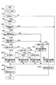
- the departure avoidance device 10 functionally includes a boundary detection unit 12, a departure prediction unit 14, an object detection unit 16, a command value adjustment unit 18, an object parameter recognition unit 20, a generation control unit 22, and a departure avoidance. Part 24. The function of each part of the deviation avoidance device 10 will be described later.
- the traveling control device 30 acquires the steering torque when the driver operates the steering wheel from the torque sensor 64, and acquires the vehicle speed of the host vehicle 100 from the vehicle speed sensor 62. Then, the travel control device 30 calculates the assist torque output by the steering motor 32 that assists the steering by the driver based on the steering torque and the vehicle speed. Then, the traveling control device 30 controls the assist amount of the force with which the driver turns the steering wheel by controlling the steering motor 32 with the energization amount according to the calculation result.
- the traveling control device 30 controls the amount of current supplied to the steering motor 32 in accordance with a command from the departure avoiding device 10. Control the state.
- the steering motor 32 corresponds to a steering actuator that drives a steering mechanism that changes the traveling direction of the host vehicle.
- the traveling control device 30 controls the traveling state of the host vehicle by controlling not only the power supply control to the steering motor 32 but also a brake system and a powertrain system (not shown).
- the traveling state of the host vehicle includes the vehicle speed in the front-rear direction and the lateral direction of the host vehicle, the lateral position on the travel path, the acceleration in the front-rear direction, the lateral direction, and the like.
- the departure avoidance start switch 50 is installed on the front panel, for example. When the departure avoidance start switch 50 is turned on, the departure avoidance process executed by the departure avoidance apparatus 10 is started. At this time, the display 40 displays that the departure avoidance support is performed.
- the display 40 may be a display of a navigation device (not shown) or a dedicated display for departure avoidance processing.
- the camera 54 images the front of the host vehicle 100.
- the departure avoidance device 10 analyzes image data of an image captured by the camera 54.
- the acceleration sensor 56 detects the acceleration in the front-rear direction and the lateral direction of the host vehicle 100.
- the yaw rate sensor 58 detects the turning angular velocity of the host vehicle 100.
- the steering angle sensor 60 detects the steering angle of a handle (not shown).
- the vehicle speed sensor 62 detects the current vehicle speed of the host vehicle 100.
- the torque sensor 64 detects torque when the driver steers the steering wheel.
- a departure avoidance process executed by the departure avoidance apparatus 10 will be described.
- the departure avoidance process is executed at predetermined time intervals when the departure avoidance activation switch 50 is turned on.
- the departure avoidance apparatus 10 acquires various parameters.
- the boundary detection unit 12 detects the boundary of the travel path 200 on which the host vehicle 100 travels from image data captured by the camera 54.
- the object detection unit 16 detects the position and type of an object included in the image data from the image data.
- the object detection unit 16 detects the distance between the host vehicle 100 and the object based on the lower end position of the object in the captured image captured by the camera 54. It can be determined that the distance between the host vehicle 100 and the object is farther as the lower end position of the object is higher in the captured image.
- the object detection unit 16 determines the type of the object by pattern matching using a dictionary of object models stored in advance.
- the object parameter recognition unit 20 recognizes the relative movement vector of the object with respect to the host vehicle by tracking the position and type of the object in time series.
- the object parameter recognition unit 20 also recognizes the distance between the object and the boundary between the traveling paths, that is, how far the object is away from the boundary. In the process of S10, the position of these boundaries, the position and type of the object, the relative movement vector, the distance between the object and the boundary of the travel path, and the like are acquired as various parameters.
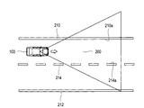
- the boundary detection unit 12 determines whether or not the boundary of the travel path 200 on which the host vehicle 100 travels has been detected.
- the boundary of the travel path 200 defines both ends of the travel path 200 in the width direction.
- the inner end 210 a of the left white line 210 and the inner end 214 a and a of the center line 214 are defined as both ends in the width direction of the travel path 200.
- the white lines 210 and 212 and the road center line 214 are recognized, for example, by analyzing image data. Not only the inner ends 210a and 214a, but also arbitrary positions on the white line 210 and the center line 214 set in advance, such as the outer ends of the white line 210 and the center line 214, may be used as boundaries.
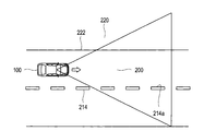
- FIG. 4 there is no white line on the left side that is one end side of both sides in the width direction of the traveling path 200 with respect to the host vehicle 100, and the boundary between the pavement surface suitable for traveling and the portion 220 inappropriate for traveling Is detected as the suitability boundary 222 of the travel path 200 defined by the suitability of travel.
- the inner end 210a of the white line 210 and the suitability boundary 222 are sometimes collectively referred to as a boundary.
- a boundary between the pavement surface and a portion unsuitable for driving is detected as a proper boundary on both sides in the width direction of the road. .
- the boundary between the pavement surface and a portion unsuitable for traveling is an appropriate boundary on the right side that is one end side on both sides in the width direction of the traveling path on which the host vehicle 100 travels.
- the suitability boundary 222 between the paved surface and the portion 220 unsuitable for traveling is recognized, for example, when the boundary detection unit 12 or the object detection unit 16 analyzes the image data.
- the right boundary at both ends in the width direction of the travel path 200 is defined by the inner end 214 a of the center line 214.
- a boundary between the portion suitable for traveling of the host vehicle 100 and the portion 220 inappropriate for traveling on the end side is defined.
- the suitability boundary 222 of the travel path 200 defined by the suitability of travel is used.
- the portion suitable for traveling of the host vehicle 100 is a paved surface or a road surface that is flat enough to allow the host vehicle 100 to travel even if it is not paved.
- the portion 220 unsuitable for traveling of the host vehicle 100 is a portion in which the host vehicle 100 cannot travel due to a structure such as a wall, a building, a guardrail, a lane defining a lane, a groove, a step, a cliff, or sand, or is difficult to travel. That is.
- the boundary detection unit 12 detects the width of the traveling road 200 in addition to detecting the boundary of the traveling road 200. Further, the boundary detection unit 12 detects the coordinates of the boundary of the traveling road 200 within the range of the captured image captured by the camera 54. Then, the boundary detection unit 12 calculates the curvature of the travel path 200 based on the coordinates of the boundary. The boundary detection unit 12 may acquire the curvature of the travel path 200 based on map information of a navigation device (not shown).
- the boundary detection unit 12 detects, for example, the boundary of the traveling road 200 or the lateral position of the host vehicle 100 with respect to the center line as the reference point of the traveling road 200 based on the image data. If the boundary detection unit 12 cannot detect the boundary of the travel path 200 in S20, the process proceeds to S230, and the departure avoidance unit 24 stops the departure avoidance control that avoids the own vehicle 100 deviating outside the travel path 200. Is commanded to the traveling control device 30, and this process is terminated. Instructing the travel control device 30 to stop the departure avoidance control includes continuing the current travel control when the travel control device 30 is not executing the departure avoidance control.
- the boundary detection unit 12 determines that the boundary of the traveling road cannot be detected.
- the process proceeds to S30, and the generation control unit 22 generates an image indicating the recognition state of the white line as one aspect of the boundary, and displays the generated image on the display 40. .
- the generation control unit 22 displays the white line icon 71 that is an image prepared in advance on the display 40 as shown in FIG. 5A.
- an image different from the white line icon 71 such as a line segment thinner than the white line icon 71 is displayed on the display 40 for the unrecognized white line icon 71, for example.
- the generation control unit 22 generates an image indicating the recognition state of the white line on the right side of the host vehicle and an image indicating the recognition state of the left side of the host vehicle separately on the left and right sides and displays them on the display 40.
- the image displayed on the display 40 is a position image indicating the position of the white line or the position of the object.
- the departure prediction unit 14 determines whether or not the own vehicle 100 has departed depending on whether or not the own vehicle 100 has reached a control start position at which the departure avoiding unit 24 causes the travel control device 30 to start departure avoidance control. Determine whether or not.
- the timing at which the traveling control device 30 starts the departure avoidance control is defined by the control start position.
- the control start position is obtained from the map as a distance from the boundary on the departure side to the inside of the travel path 200, using the lateral speed of the host vehicle 100, the curvature of the travel path 200, the width of the travel path 200, etc. as parameters.
- reference numeral 300 indicates the control start position.
- the departure prediction unit 14 predicts that the host vehicle 100 reaches the control start position 300 and departs from the travel path 200.
- the control start position 300 indicates a position at which the host vehicle 100 reaches the boundary of the travel path in a preset arrival time when the host vehicle 100 moves from the control start position 300 at the current lateral speed, for example.
- the process proceeds to S230, and the departure avoidance unit 24 causes the travel control device 30 to stop the departure avoidance control, and this process is terminated.
- the departure prediction unit 14 predicts that the host vehicle 100 will depart outside the travel path 200. In this case, in the processes of S50 and S60, the departure prediction unit 14 determines whether or not an object exists on the departure side boundary or outside the boundary.
- the process proceeds to S70 described later. If there is an object on or outside the boundary on the departure side in S50, the process proceeds to S60, and the departure prediction unit 14 determines the distance between the object and the boundary of the travel path, that is, how far the object is from the boundary. Determine if they are outside. That is, the departure prediction unit 14 determines whether or not the distance between the object and the boundary is equal to or greater than the allowable distance that the host vehicle 100 may deviate outside the boundary when there is no object outside the boundary or the boundary. judge. In this embodiment, the allowable distance is set to 45 cm.
- the process proceeds to S70.
- the object parameter recognition unit 20 determines whether or not the detected boundary on the departure side of the travel path 200 is a white line.
- the white line includes a center line and a yellow line.
- the process proceeds to S80.
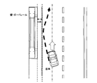
- the object parameter recognition unit 20 sets a command value to be instructed to the travel control device 30 in order to avoid the departure of the host vehicle 100. For example, as shown in FIG. 6, the object parameter recognizing unit 20 sets the target position 310 of the maximum movement position where the own vehicle 100 moves most on the departure side on the departure side from the departure side boundary on the departure side.
- the distance D is set to +30 cm from the inner end 210a of the white line 210.
- the process proceeds to S240.
- the plus sign of +30 cm indicates that it is outside the traveling road 200 from the inner end 210a of the white line 210 on the departure side.
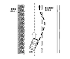
- the object parameter recognition unit 20 sets a command value to be instructed to the travel control device 30 in order to avoid the departure of the host vehicle 100. For example, as shown in FIG. 7, the object parameter recognition unit 20 sets the target position 310 of the maximum movement position to a distance D of “boundary ⁇ L3 cm” with respect to the suitability boundary 222 on the departure side.
- the process proceeds to S240.
- L3 is a positive value, it indicates that the set target position 310 is inside the traveling path 200 from the suitability boundary 222 on the departure side.
- L3 cm is set to 5 cm, for example.
- the process proceeds to S120, and the object detection unit 16 determines whether or not the object is a vehicle.
- the object parameter recognizing unit 20 is a parked vehicle representing a vehicle in which the vehicle is parked, a parallel running vehicle that runs in the same direction as the own vehicle, and a direction opposite to the own vehicle. It is determined based on the relative speed between the host vehicle and the object.
- the process proceeds to S130, and the generation control unit 22 reads the vehicle icon 72, which is a picture representing the vehicle, from the memory, and displays the image on the display 40. Specifically, as illustrated in FIG. 5A, the generation control unit 22 arranges the vehicle icon 72 at a position corresponding to the positional relationship with a boundary such as a white line, and sets the relative movement direction of the vehicle around the vehicle icon 72. An arrow image 73 is displayed. In the arrow image, the direction indicated by the arrow indicates the relative movement direction of the vehicle.
- the image example shown in FIG. 5A shows a situation in which a vehicle having a higher speed than the host vehicle is running in parallel on the adjacent traveling path adjacent to the traveling path of the host vehicle, as shown in FIG. 5B.
- the image shown in FIG. 5A can represent the recognition state of the white line, the relationship of the position of the object with respect to the position of the white line, the relative movement direction of the object, the type of the object, and the like.
- the object parameter recognizing unit 20 sets a command value to be instructed to the travel control device 30 in order to avoid deviation of the host vehicle 100.
- the object parameter recognition unit 20 sets the target position 310 of the maximum movement position to the distance D of “boundary ⁇ L2 cm” with the inner end 210a of the departure-side white line 210 as a boundary, and the process proceeds to S240.
- L2 is a positive value, and L1> L2> L3.
- L2 cm is set to 10 cm, for example.
- the boundary display process is a process of displaying an image according to the type of the object when the type of the object is other than a vehicle or a pedestrian.
- the object parameter recognition unit 20 determines whether or not the detected object is a guardrail. If the object is a guard rail in S310, the process proceeds to S320. In S320, the generation control unit 22 displays an image indicating the guardrail on the display 40, and ends the boundary display process.
- FIG. 9B As an image showing the guardrail, for example, as shown in FIG. 9B, when a white line and a guardrail are detected on one side of the vehicle, an image including both icons indicating these is generated as shown in FIG. 9A. You may make it display.
- the white line icon 71 is displayed on the right side of the host vehicle, the white line is recognized on the left side, and the in-control icon 78 indicating that departure avoidance control is being performed, and the guardrail icon 82 indicating the guardrail. Is displayed.
- the process proceeds to S330, and the object parameter recognition unit 20 determines whether or not the object is another three-dimensional object.
- the other three-dimensional object indicates a portion 220 that is not suitable for the traveling of the host vehicle 100 described above.
- S330 if the object is another three-dimensional object, the process proceeds to S340.
- the generation control unit 22 displays an image indicating the suitability boundary 222 on the display 40, and then ends the boundary display process.
- the generation control unit 22 displays a suitability boundary icon 83 indicating the suitability boundary 222. If the object is not another three-dimensional object in S330, the boundary display process ends.
- the object parameter recognition unit 20 sets a command value to be instructed to the travel control device 30 in order to avoid the departure of the host vehicle 100.
- the object parameter recognition unit 20 sets the target position 310 of the maximum movement position with respect to the boundary between the traveling path 200 and the pole 230 as a distance D of “boundary ⁇ L3 cm”. Subsequently, the process proceeds to S240.
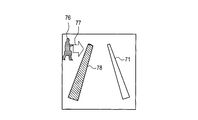
- the generation control unit 22 causes the display 40 to display an image indicating a pedestrian.
- the image indicating the pedestrian displays a pedestrian icon 76 that is a picture prepared in advance as an image indicating the pedestrian in the memory.
- an arrow icon 77 indicating the moving direction of the pedestrian is also displayed.
- the pedestrian icon 76 is displayed together with the white line icon 71 in this way only when a person such as a pedestrian is located within 45 cm from the white line as shown in FIG. 11B, for example. This is because only the person necessary for the control is displayed as the pedestrian icon 76.
- pattern matching using a pedestrian dictionary for estimating the direction of movement from the shape of the pedestrian is performed, or images are tracked in time series. .
- the generation control unit 22 performs a display during control.
- the display during control is a display indicating that departure avoidance control is being performed.
- an in-control icon 78 in which the deviation-side white line icon 71 among the left and right white line icons 71 is highlighted is displayed.
- the in-control icon 78 shows a white line on the left side which is the departure side in FIG. 12, and the white line icon 71 is devised so as to attract the driver's attention by changing the color or blinking.
- the object parameter recognizing unit 20 sets a command value to be instructed to the travel control device 30 in order to avoid the departure of the host vehicle 100.
- the object parameter recognition unit 20 sets the target position 310 of the maximum movement position to a distance D of “boundary ⁇ L1 cm” with the inner end 210a of the departure-side white line 210 as a boundary.
- the process proceeds to S240.
- L1 is a positive value, and L1> L3.
- L1 cm is set to 15 cm, for example.
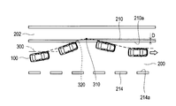
- the departure avoidance unit 24 instructs the travel control device 30 to set a target line 320 on which the host vehicle 100 travels during the departure avoidance process.
- the travel control device 30 performs deviation avoidance control by feedback-controlling energization to the steering motor 32 so that the host vehicle 100 travels on the commanded target line 320.
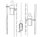
- the departure avoidance unit 24 performs offset control to move the lateral position where the host vehicle travels on the travel path to the far side from the person when a person is detected within a predetermined distance from the white line.
- the generation control unit 22 displays an offset icon 79 indicating that the offset control is being performed. For example, when a pedestrian is detected on the left side of the travel path, the travel position is offset to the right by about 20 cm in the width direction.
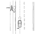
- the generation control unit 22 displays a down arrow icon 74 representing the approach of the vehicle together with the vehicle icon 72A. 40.
- the vehicle icon 72A to be displayed is an icon indicating an oncoming vehicle, and is set to a color different from the vehicle icon 72 indicating a parallel running vehicle, for example.
- the vehicle icon 72 indicating a parallel running vehicle and the vehicle icon 72A indicating an oncoming vehicle may be set to different patterns.
- the boundary detection unit 12 acquires the position of the boundary that defines both ends in the width direction of the travel path on which the host vehicle travels, and the object detection unit 16 Acquires the position of surrounding objects.
- the generation control unit 22 generates a position image that is an image indicating the position of the boundary and the position of the object, and causes the display device to display the position image.
- the departure avoidance apparatus 10 of the departure avoidance system 2 is configured to include an image indicating whether or not the position of the boundary portion has been acquired as the position image. According to such a departure avoidance system 2, it is possible to make the occupant recognize whether or not the position of the boundary portion has been acquired.
- the position of the boundary portion is acquired for each of the right side and the left side of the traveling path, and the boundary portion positioned on the right side of the traveling path and the position of the traveling path are obtained as position images.
- the boundary part located in the left side it is comprised so that the image which shows whether each position has been acquired can be included.
- the departure avoidance device 10 of the departure avoidance system 2 is configured to recognize the moving direction of an object and include an image indicating the moving direction of the object as a position image.
- the departure avoidance apparatus 10 of the departure avoidance system 2 is configured to recognize the type of an object and represent the position of the object using an image indicating the type of the object.
- the departure avoidance device 10 of the departure avoidance system 2 recognizes the relative speed between the host vehicle and the object, recognizes whether the object is a vehicle, and recognizes the recognition when the object is a vehicle. Based on the relative speed, the vehicle is recognized as a parallel vehicle traveling in the same direction as the own vehicle or a non-parallel vehicle traveling in a different direction from the own vehicle. If the recognized vehicle is a parallel vehicle, an image indicating a parallel vehicle is generated. If the recognized vehicle is a non-parallel vehicle, a non-parallel vehicle different from the image indicating the parallel vehicle is generated.
- the position image is configured to include an image indicating a parallel running vehicle or a non-parallel running vehicle.
- the departure avoidance device 10 of the departure avoidance system 2 recognizes whether or not the object is a person, and when recognizing the person, generates an image showing the pedestrian and displays the pedestrian as a position image. It is comprised so that the image shown may be included.
- the departure avoidance apparatus 10 of the departure avoidance system 2 is configured to generate a position image by combining an object icon indicating an object with a pattern and a boundary icon indicating a boundary portion with a pattern.
- the departure avoidance device 10 of the departure avoidance system 2 is configured to acquire a recognition result of a suitability boundary representing a boundary between an unsuitable portion 220 representing a portion unsuitable for traveling of the host vehicle and a travel path as a boundary portion. Has been.
- a boundary with a portion unsuitable for traveling of the host vehicle can be acquired as a proper boundary.
- the departure avoidance apparatus 10 of the departure avoidance system 2 it is predicted that the own vehicle deviates from the traveling road based on the traveling state of the own vehicle traveling on the traveling road defined by the boundary portion. Then, when the own vehicle deviates from the traveling road, the departure prediction unit predicts, and when the own vehicle departs from the traveling road or an object exists outside the boundary portion, the own vehicle moves to the deviating side.
- the travel control device that controls the travel state is instructed so that the maximum movement position of the vehicle is on the inner side of the travel path than when the vehicle is deviating from the travel path or on the outer side of the boundary. Thus, the host vehicle is prevented from deviating from the travel path.
- the inside indicates a direction approaching a position where the host vehicle should travel in a lateral position in the travel path.
- the object is positioned around the boundary portion of the traveling road, and the traveling track of the vehicle by the control that suppresses the departure from the traveling road is changed to be more inside the traveling road. At this time, it is possible to notify the occupant of performing such control by displaying the position image.
- the second embodiment is different from the first embodiment in that the image display mode is set in consideration of the driver's psychological pressure, in other words, the psychological margin, in the departure avoidance process.
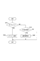
- the departure avoidance process executed by the departure avoidance apparatus 10 of the second embodiment instead of the departure avoidance process of the first embodiment shown in FIG. 2 will be described with reference to the flowchart of FIG.
- the process of S410 is performed following the process of S10, and the psychological pressure is calculated in the process of S410.
- Psychological pressure is a numerical value of how much fear the driver of the own vehicle feels about the presence of another vehicle. In order to calculate the psychological pressure, for example, a distance from an object such as another vehicle and a vehicle speed that is the speed of the host vehicle are used.
- a map is used in which the vertical axis represents the distance in the traveling direction of the host vehicle, and the horizontal axis represents the vehicle speed of the host vehicle.
- This map shows that the psychological pressure increases as the vertical distance decreases and the vehicle speed increases.
- a threshold is provided at a position where the vertical distance is 15 m until the vehicle speed is 40 km / h, and a threshold is provided so that the vertical distance increases as the vehicle speed increases when the vehicle speed is 40 km / h or higher.
- the psychological pressure increases as the distance to the line segment indicated by the threshold increases. Set to increase the degree of pressure. However, it is assumed that there is no psychological pressure in the area above the line segment indicated by the threshold in the map.
- a display mode for displaying the vehicle on the display 40 is set.
- the display mode is set using a map that sets the display mode based on the relative speed with the other vehicle and the calculated psychological pressure. That is, as shown in FIG. 17, the display mode is set according to whether the position on the map specified by the relative speed and the psychological pressure is an area that displays highlighting or an area that performs normal display. In the example shown in FIG. 17, an object with a small relative speed is set to be easily highlighted.
- the flashing vehicle icon 81 is set to be displayed.
- the display method is not limited to blinking, and may be any display method that attracts the driver's attention as compared to the normal vehicle icon 72, such as changing the color.
- the degree of psychological pressure felt by the driver of the host vehicle is estimated, and the display mode of the image is changed according to the degree of psychological pressure.
- the icon indicating the vehicle blinks or the display color is changed to a color that calls attention (for example, yellow or red)
- the driver is alerted by changing the display mode.
- the departure avoidance device 10 is configured to change the distance between the object icon and the boundary icon in the position image as the distance based on the acquired object position and boundary position increases. May be.
- the object icon is an icon indicating an object such as a vehicle or a pedestrian
- the boundary icon is an icon indicating a white line or a suitability boundary.
- the vehicle icon 72 when the detected vehicle is on the white line, the vehicle icon 72 is displayed over the white line icon 71. Further, as shown in FIG. 19B, when the detected vehicle travels about 30 cm from the white line, the vehicle icon 72 is displayed slightly apart from the white line icon 71. Further, as shown in FIG. 19C, when the detected vehicle travels a position about 30 cm or more away from the white line, the vehicle icon 72 is displayed farther from the white line icon 71 than in the case shown in FIG. 19B.
- the distance between the object icon and the boundary icon can be expressed by the position image.
- the departure avoidance device 10 may be configured to generate an image indicating the distance between the object and the boundary portion as a numerical value, and include an image indicating the distance as a numerical value as the position image. For example, as shown in FIG. 20, a numerical icon 85 indicating the distance between the white line and the vehicle may be displayed between the white line icon 71 and the vehicle icon 72.
- the distance between the object and the boundary portion in the position image can be recognized numerically.
- the functions of one component in the above embodiment may be distributed as a plurality of components, or the functions of a plurality of components may be integrated into one component. Moreover, you may abbreviate
- non-transitional actual records such as a device serving as a component of the departure avoidance system, a program for causing a computer to function as the departure avoidance system, and a semiconductor memory storing the program
- the present invention can also be realized in various forms such as a medium and a deviation avoidance method.
- the deviation avoidance device 10 corresponds to a display control device according to the present invention
- the boundary detection unit 12 corresponds to a boundary acquisition unit according to the present invention
- the object detection unit 16 corresponds to an object acquisition unit referred to in the present invention
- the object parameter recognition unit 20 includes a movement recognition unit, an object type recognition unit, and a relative speed recognition unit referred to in the present invention. It corresponds to.
- the boundary acquisition unit (12) acquires the position of the boundary part that defines both ends in the width direction of the travel path (200) on which the host vehicle travels, and the object acquisition unit (16). Acquires the position of an object located around the road.
- the generation control unit (22) generates a position image that is an image indicating the position of the boundary and the position of the object, and displays the position image on the display device.
Priority Applications (3)
| Application Number | Priority Date | Filing Date | Title |
|---|---|---|---|
| DE112016004693.6T DE112016004693T5 (de) | 2015-10-16 | 2016-10-14 | Anzeigesteuerapparat und Fahrzeugsteuerapparat |
| CN201680060471.9A CN108140325A (zh) | 2015-10-16 | 2016-10-14 | 显示控制装置以及车辆控制装置 |
| US15/768,223 US11514793B2 (en) | 2015-10-16 | 2016-10-14 | Display control apparatus and vehicle control apparatus |
Applications Claiming Priority (2)
| Application Number | Priority Date | Filing Date | Title |
|---|---|---|---|
| JP2015-204596 | 2015-10-16 | ||
| JP2015204596A JP6613795B2 (ja) | 2015-10-16 | 2015-10-16 | 表示制御装置および車両制御装置 |
Publications (1)
| Publication Number | Publication Date |
|---|---|
| WO2017065297A1 true WO2017065297A1 (ja) | 2017-04-20 |
Family
ID=58517213
Family Applications (1)
| Application Number | Title | Priority Date | Filing Date |
|---|---|---|---|
| PCT/JP2016/080612 WO2017065297A1 (ja) | 2015-10-16 | 2016-10-14 | 表示制御装置および車両制御装置 |
Country Status (5)
| Country | Link |
|---|---|
| US (1) | US11514793B2 (zh) |
| JP (1) | JP6613795B2 (zh) |
| CN (1) | CN108140325A (zh) |
| DE (1) | DE112016004693T5 (zh) |
| WO (1) | WO2017065297A1 (zh) |
Cited By (1)
| Publication number | Priority date | Publication date | Assignee | Title |
|---|---|---|---|---|
| JP2019026208A (ja) * | 2017-08-03 | 2019-02-21 | 株式会社Subaru | 車両の運転支援装置 |
Families Citing this family (12)
| Publication number | Priority date | Publication date | Assignee | Title |
|---|---|---|---|---|
| EP3217374A1 (en) * | 2016-03-10 | 2017-09-13 | Volvo Car Corporation | Method and system for estimating a boundary of a road technical field |
| EP3551966B1 (en) * | 2016-12-06 | 2021-03-03 | Nissan North America, Inc. | Solution path overlay interfaces for autonomous vehicles |
| JP7266257B2 (ja) * | 2017-06-30 | 2023-04-28 | パナソニックIpマネジメント株式会社 | 表示システム、及び表示システムの制御方法 |
| US10913454B2 (en) * | 2017-12-13 | 2021-02-09 | Humanising Autonomy Limited | Systems and methods for predicting pedestrian intent |
| EP3617941A1 (en) * | 2018-08-30 | 2020-03-04 | Panasonic Intellectual Property Corporation of America | Information processing apparatus and information processing method |
| JP7265404B2 (ja) * | 2018-08-30 | 2023-04-26 | パナソニック インテレクチュアル プロパティ コーポレーション オブ アメリカ | 情報処理装置及び情報処理方法 |
| CN109724614B (zh) * | 2019-02-22 | 2021-06-04 | 百度在线网络技术(北京)有限公司 | 自动驾驶车辆的速度规划方法、装置和存储介质 |
| WO2020208989A1 (ja) * | 2019-04-09 | 2020-10-15 | 株式会社デンソー | 表示制御装置及び表示制御プログラム |
| DE102019207951B4 (de) * | 2019-05-29 | 2022-06-30 | Volkswagen Aktiengesellschaft | Verfahren zum Durchführen einer Korrektur der Fahrtrichtung durch ein Fahrerassistenzsystem in einem Kraftfahrzeug sowie eine Steuervorrichtung hierzu |
| JP7125239B2 (ja) * | 2019-07-31 | 2022-08-24 | トヨタ自動車株式会社 | 車両の注意喚起装置 |
| JP7357284B2 (ja) | 2020-02-12 | 2023-10-06 | パナソニックIpマネジメント株式会社 | 描画システム、表示システム、移動体、描画方法及びプログラム |
| CN112373488B (zh) * | 2020-12-14 | 2021-12-28 | 长春汽车工业高等专科学校 | 一种基于人工智能的无人驾驶系统及方法 |
Citations (6)
| Publication number | Priority date | Publication date | Assignee | Title |
|---|---|---|---|---|
| JP2005056372A (ja) * | 2003-03-26 | 2005-03-03 | Fujitsu Ten Ltd | 車両制御装置、車両制御方法および車両制御プログラム |
| JP2008059458A (ja) * | 2006-09-01 | 2008-03-13 | Toyota Motor Corp | 車車間通信システム、車載装置、及び運転支援装置 |
| JP2013120574A (ja) * | 2011-12-08 | 2013-06-17 | Daimler Ag | 車両用歩行者報知装置 |
| JP5316713B2 (ja) * | 2011-06-08 | 2013-10-16 | トヨタ自動車株式会社 | 車線逸脱防止支援装置、車線逸脱防止方法、記憶媒体 |
| JP5616531B2 (ja) * | 2011-09-21 | 2014-10-29 | 本田技研工業株式会社 | 車両周辺監視装置 |
| JP2015096946A (ja) * | 2013-10-10 | 2015-05-21 | パナソニックIpマネジメント株式会社 | 表示制御装置、表示制御プログラム、および表示制御方法 |
Family Cites Families (35)
| Publication number | Priority date | Publication date | Assignee | Title |
|---|---|---|---|---|
| JPS5921360B2 (ja) | 1976-07-31 | 1984-05-19 | ライオン株式会社 | 粒状洗剤の改質方法 |
| WO2005080120A1 (en) * | 2004-02-20 | 2005-09-01 | Sharp Kabushiki Kaisha | Condition detection and display system, condition detection and display method, control program for condition detection and display system, and storage medium storing the control program |
| JP4297045B2 (ja) * | 2004-12-14 | 2009-07-15 | 株式会社デンソー | ヘッドアップディスプレイの表示制御装置およびプログラム |
| US8164628B2 (en) * | 2006-01-04 | 2012-04-24 | Mobileye Technologies Ltd. | Estimating distance to an object using a sequence of images recorded by a monocular camera |
| DE102007027495A1 (de) | 2007-06-14 | 2008-12-18 | Daimler Ag | Verfahren zur Unterstützung des Fahrers eines Kraftfahrzeuges bei der Querführung des Kraftfahrzeugs |
| JP5104171B2 (ja) * | 2007-09-28 | 2012-12-19 | 日産自動車株式会社 | 駐車支援装置および駐車支援方法 |
| JP4730406B2 (ja) * | 2008-07-11 | 2011-07-20 | トヨタ自動車株式会社 | 走行支援制御装置 |
| US8099213B2 (en) * | 2008-07-18 | 2012-01-17 | GM Global Technology Operations LLC | Road-edge detection |
| US8305444B2 (en) | 2008-11-14 | 2012-11-06 | Toyota Motor Engineering & Manufacturing North America, Inc. | Integrated visual display system |
| JP2010173530A (ja) | 2009-01-30 | 2010-08-12 | Toyota Motor Corp | 走行支援装置 |
| US8629903B2 (en) | 2009-04-02 | 2014-01-14 | GM Global Technology Operations LLC | Enhanced vision system full-windshield HUD |
| JP5287746B2 (ja) * | 2009-05-21 | 2013-09-11 | 日産自動車株式会社 | 運転支援装置、及び運転支援方法 |
| US9041806B2 (en) * | 2009-09-01 | 2015-05-26 | Magna Electronics Inc. | Imaging and display system for vehicle |
| US8655579B2 (en) * | 2010-03-16 | 2014-02-18 | Toyota Jidosha Kabushiki Kaisha | Driving assistance device |
| JP2011215872A (ja) * | 2010-03-31 | 2011-10-27 | Aisin Aw Co Ltd | 運転支援装置、運転支援方法、及び運転支援プログラム |
| DE102010042063B4 (de) * | 2010-10-06 | 2021-10-28 | Robert Bosch Gmbh | Verfahren und Vorrichtung zum Bestimmen von aufbereiteten Bilddaten über ein Umfeld eines Fahrzeugs |
| US9318023B2 (en) * | 2011-08-31 | 2016-04-19 | GM Global Technology Operations LLC | System and method for collision avoidance maneuver path determination with jerk limit |
| CN103987559B (zh) * | 2011-12-14 | 2016-11-16 | 丰田自动车株式会社 | 车辆用信息传递装置 |
| CN103182984B (zh) * | 2011-12-28 | 2015-08-26 | 财团法人车辆研究测试中心 | 车用影像显示系统及其校正方法 |
| JP5543501B2 (ja) * | 2012-01-27 | 2014-07-09 | 株式会社日本自動車部品総合研究所 | 車両制御装置 |
| CN202454087U (zh) * | 2012-02-27 | 2012-09-26 | 上海理工大学 | 一种车载道路边缘检测装置 |
| CN102582599A (zh) * | 2012-03-07 | 2012-07-18 | 浙江吉利汽车研究院有限公司 | 车辆制动控制系统以及车辆紧急制动避让方法 |
| CN102682292B (zh) * | 2012-05-10 | 2014-01-29 | 清华大学 | 基于单目视觉的道路边缘检测及粗定位方法 |
| CN202593376U (zh) * | 2012-05-25 | 2012-12-12 | 浙江吉利汽车研究院有限公司杭州分公司 | 车辆可通过性预判断及辅助系统 |
| US8849515B2 (en) * | 2012-07-24 | 2014-09-30 | GM Global Technology Operations LLC | Steering assist in driver initiated collision avoidance maneuver |
| CN103885573B (zh) * | 2012-12-19 | 2017-03-01 | 财团法人车辆研究测试中心 | 车用显示系统的自动校正方法及其系统 |
| JP2014133512A (ja) | 2013-01-11 | 2014-07-24 | Nissan Motor Co Ltd | 車両用表示制御装置及び車両用表示制御方法 |
| DE102013016242A1 (de) | 2013-10-01 | 2015-04-02 | Daimler Ag | Verfahren und Vorrichtung zur Unterstützung mindestens eines Fahrassistenzsystems |
| US9212926B2 (en) * | 2013-11-22 | 2015-12-15 | Ford Global Technologies, Llc | In-vehicle path verification |
| KR20150059489A (ko) * | 2013-11-22 | 2015-06-01 | 현대자동차주식회사 | 협로 검출 방법과 협로 검출 장치 및 협로 검출 시스템 |
| JP2015155878A (ja) * | 2014-02-21 | 2015-08-27 | 株式会社デンソー | 車両用障害物検出装置 |
| TWI600558B (zh) * | 2014-04-01 | 2017-10-01 | Dynamic lane detection system and method | |
| JP6423678B2 (ja) * | 2014-10-07 | 2018-11-14 | 東京エレクトロン株式会社 | 基板検査装置及びその制御方法 |
| JP6657618B2 (ja) | 2015-06-30 | 2020-03-04 | 株式会社デンソー | 逸脱回避装置 |
| US10607485B2 (en) * | 2015-11-11 | 2020-03-31 | Sony Corporation | System and method for communicating a message to a vehicle |
-
2015
- 2015-10-16 JP JP2015204596A patent/JP6613795B2/ja active Active
-
2016
- 2016-10-14 US US15/768,223 patent/US11514793B2/en active Active
- 2016-10-14 CN CN201680060471.9A patent/CN108140325A/zh active Pending
- 2016-10-14 DE DE112016004693.6T patent/DE112016004693T5/de active Pending
- 2016-10-14 WO PCT/JP2016/080612 patent/WO2017065297A1/ja active Application Filing
Patent Citations (6)
| Publication number | Priority date | Publication date | Assignee | Title |
|---|---|---|---|---|
| JP2005056372A (ja) * | 2003-03-26 | 2005-03-03 | Fujitsu Ten Ltd | 車両制御装置、車両制御方法および車両制御プログラム |
| JP2008059458A (ja) * | 2006-09-01 | 2008-03-13 | Toyota Motor Corp | 車車間通信システム、車載装置、及び運転支援装置 |
| JP5316713B2 (ja) * | 2011-06-08 | 2013-10-16 | トヨタ自動車株式会社 | 車線逸脱防止支援装置、車線逸脱防止方法、記憶媒体 |
| JP5616531B2 (ja) * | 2011-09-21 | 2014-10-29 | 本田技研工業株式会社 | 車両周辺監視装置 |
| JP2013120574A (ja) * | 2011-12-08 | 2013-06-17 | Daimler Ag | 車両用歩行者報知装置 |
| JP2015096946A (ja) * | 2013-10-10 | 2015-05-21 | パナソニックIpマネジメント株式会社 | 表示制御装置、表示制御プログラム、および表示制御方法 |
Cited By (1)
| Publication number | Priority date | Publication date | Assignee | Title |
|---|---|---|---|---|
| JP2019026208A (ja) * | 2017-08-03 | 2019-02-21 | 株式会社Subaru | 車両の運転支援装置 |
Also Published As
| Publication number | Publication date |
|---|---|
| JP6613795B2 (ja) | 2019-12-04 |
| CN108140325A (zh) | 2018-06-08 |
| US11514793B2 (en) | 2022-11-29 |
| JP2017076324A (ja) | 2017-04-20 |
| DE112016004693T5 (de) | 2018-06-28 |
| US20180322787A1 (en) | 2018-11-08 |
Similar Documents
| Publication | Publication Date | Title |
|---|---|---|
| JP6613795B2 (ja) | 表示制御装置および車両制御装置 | |
| US10810446B2 (en) | Parking space line detection method and device | |
| US9862416B2 (en) | Automatic parking control device, and parking assistance device | |
| JP6515823B2 (ja) | 車線変更支援装置 | |
| JP4638370B2 (ja) | 車線逸脱防止装置 | |
| JP6368574B2 (ja) | 車両制御装置 | |
| US10843729B2 (en) | Deviation avoidance apparatus | |
| US9734719B2 (en) | Method and apparatus for guiding a vehicle in the surroundings of an object | |
| JP6460992B2 (ja) | 車線を逸脱した後の車両の復帰をサポートするための方法、並びに、装置 | |
| EP3919336B1 (en) | Travel control method and travel control device for vehicle | |
| JP2007253745A (ja) | 回避操作算出装置、回避制御装置、各装置を備える車両、回避操作算出方法および回避制御方法 | |
| JP6196518B2 (ja) | 運転支援装置 | |
| JP6377942B2 (ja) | 運転支援装置 | |
| WO2019155880A1 (ja) | 車両制御装置 | |
| JP2009286279A (ja) | 車両の運転支援装置 | |
| JP2007269312A (ja) | 車両用運転操作補助装置 | |
| JP3704987B2 (ja) | 車両走行制御装置 | |
| JP6885022B2 (ja) | 運転支援装置 | |
| JP5929093B2 (ja) | 車両用走行支援装置 | |
| JP5929597B2 (ja) | 車両用走行制御装置及び方法 | |
| JP7069539B2 (ja) | 運転支援装置 | |
| JP2015067030A (ja) | 運転支援装置 | |
| JP2006176069A (ja) | インターチェンジ合流支援装置 | |
| JP6210012B2 (ja) | 車線維持制御装置 | |
| JP7176651B2 (ja) | 駐車支援方法及び駐車支援装置 |
Legal Events
| Date | Code | Title | Description |
|---|---|---|---|
| 121 | Ep: the epo has been informed by wipo that ep was designated in this application |
Ref document number: 16855550 Country of ref document: EP Kind code of ref document: A1 |
|
| WWE | Wipo information: entry into national phase |
Ref document number: 15768223 Country of ref document: US |
|
| WWE | Wipo information: entry into national phase |
Ref document number: 112016004693 Country of ref document: DE |
|
| 122 | Ep: pct application non-entry in european phase |
Ref document number: 16855550 Country of ref document: EP Kind code of ref document: A1 |