WO2017065297A1 - Display control device and vehicle control device - Google Patents
Display control device and vehicle control device Download PDFInfo
- Publication number
- WO2017065297A1 WO2017065297A1 PCT/JP2016/080612 JP2016080612W WO2017065297A1 WO 2017065297 A1 WO2017065297 A1 WO 2017065297A1 JP 2016080612 W JP2016080612 W JP 2016080612W WO 2017065297 A1 WO2017065297 A1 WO 2017065297A1
- Authority
- WO
- WIPO (PCT)
- Prior art keywords
- vehicle
- boundary
- image
- control device
- display
- Prior art date
Links
Images


Classifications
-
- G—PHYSICS
- G08—SIGNALLING
- G08G—TRAFFIC CONTROL SYSTEMS
- G08G1/00—Traffic control systems for road vehicles
- G08G1/16—Anti-collision systems
- G08G1/167—Driving aids for lane monitoring, lane changing, e.g. blind spot detection
-
- G—PHYSICS
- G08—SIGNALLING
- G08G—TRAFFIC CONTROL SYSTEMS
- G08G1/00—Traffic control systems for road vehicles
- G08G1/16—Anti-collision systems
- G08G1/165—Anti-collision systems for passive traffic, e.g. including static obstacles, trees
-
- G—PHYSICS
- G08—SIGNALLING
- G08G—TRAFFIC CONTROL SYSTEMS
- G08G1/00—Traffic control systems for road vehicles
- G08G1/16—Anti-collision systems
- G08G1/166—Anti-collision systems for active traffic, e.g. moving vehicles, pedestrians, bikes
Definitions
- the present invention relates to a display control device that displays an image on a display device visually recognized by a passenger of the host vehicle, and a vehicle control device that controls the host vehicle.
- the display control device for example, as shown in Patent Document 1, a device that recognizes a white line as a boundary of a traveling road and displays a recognition state of the white line as an image is known.
- more items can be displayed in a display control device that displays an image on a display device visually recognized by a passenger of the host vehicle.
- the display control device of the embodiment is a display control device that is mounted on a host vehicle and displays an image on a display device that is visually recognized by an occupant of the host vehicle, and defines both ends in the width direction of a traveling path on which the host vehicle travels.
- a boundary acquisition unit that acquires a position of the boundary part
- an object acquisition unit that acquires a position of an object located around the travel path
- a position image that is an image showing the position of the boundary part and the position of the object The position image is generated and displayed on the display device.
- the figure which shows the example of a display in case the white line and the guardrail are detected.
- the figure which shows the example of a display of a suitability boundary The top view which shows the surrounding condition of the own vehicle when a suitability boundary exists.
- the figure which shows the example of a display when an object is a person.
- the top view which shows the surrounding condition of the own vehicle in case an object is a person.
- the figure which shows the example of a display in case an object is an oncoming vehicle.
- the top view which shows the surrounding condition of the own vehicle when an object is an oncoming vehicle.
- the flowchart which shows the deviation avoidance process of 2nd Embodiment.
- the top view which shows the surrounding condition of the own vehicle when an object with high psychological pressure exists.
- the departure avoidance system 2 to which the present invention is applied is mounted on a vehicle such as a passenger car, and has a function of suppressing departure from a travel path on which the vehicle travels.
- a travel path shows the area
- the deviation avoidance system 2 of the present embodiment is configured to improve convenience by displaying many items on the display 40.
- “suppressing deviation” is also expressed as “avoiding deviation”.
- the departure avoidance system 2 includes a departure avoidance device 10, a travel control device 30, a steering motor 32, a display 40, a departure avoidance start switch 50, a camera 54, and an acceleration sensor 56.
- the deviation avoidance device 10 is a known computer including a CPU and a memory such as a RAM and a ROM.
- the departure avoidance device 10 executes departure avoidance processing, which will be described later, by a program stored in the memory. Further, by executing this program, a method corresponding to the program is executed.
- the number of microcomputers constituting the departure avoidance device 10 may be one or more.
- the vehicle on which the deviation avoidance device 10 is mounted is referred to as the own vehicle.
- a plurality of types of icons are recorded in advance in the memory.
- An icon represents a symbolized representation of things with a simple pattern. Specifically, an image showing a white line as a boundary, an image showing a pedestrian, an image showing a vehicle, an image showing a guardrail, which will be described later An image showing a suitability boundary is included.
- the method for realizing these elements constituting the deviation avoidance apparatus 10 is not limited to software, and some or all of the elements are realized by using hardware combining logic circuits, analog circuits, and the like. Also good.
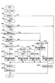
- the departure avoidance device 10 functionally includes a boundary detection unit 12, a departure prediction unit 14, an object detection unit 16, a command value adjustment unit 18, an object parameter recognition unit 20, a generation control unit 22, and a departure avoidance. Part 24. The function of each part of the deviation avoidance device 10 will be described later.
- the traveling control device 30 acquires the steering torque when the driver operates the steering wheel from the torque sensor 64, and acquires the vehicle speed of the host vehicle 100 from the vehicle speed sensor 62. Then, the travel control device 30 calculates the assist torque output by the steering motor 32 that assists the steering by the driver based on the steering torque and the vehicle speed. Then, the traveling control device 30 controls the assist amount of the force with which the driver turns the steering wheel by controlling the steering motor 32 with the energization amount according to the calculation result.
- the traveling control device 30 controls the amount of current supplied to the steering motor 32 in accordance with a command from the departure avoiding device 10. Control the state.
- the steering motor 32 corresponds to a steering actuator that drives a steering mechanism that changes the traveling direction of the host vehicle.
- the traveling control device 30 controls the traveling state of the host vehicle by controlling not only the power supply control to the steering motor 32 but also a brake system and a powertrain system (not shown).
- the traveling state of the host vehicle includes the vehicle speed in the front-rear direction and the lateral direction of the host vehicle, the lateral position on the travel path, the acceleration in the front-rear direction, the lateral direction, and the like.
- the departure avoidance start switch 50 is installed on the front panel, for example. When the departure avoidance start switch 50 is turned on, the departure avoidance process executed by the departure avoidance apparatus 10 is started. At this time, the display 40 displays that the departure avoidance support is performed.
- the display 40 may be a display of a navigation device (not shown) or a dedicated display for departure avoidance processing.
- the camera 54 images the front of the host vehicle 100.
- the departure avoidance device 10 analyzes image data of an image captured by the camera 54.
- the acceleration sensor 56 detects the acceleration in the front-rear direction and the lateral direction of the host vehicle 100.
- the yaw rate sensor 58 detects the turning angular velocity of the host vehicle 100.
- the steering angle sensor 60 detects the steering angle of a handle (not shown).
- the vehicle speed sensor 62 detects the current vehicle speed of the host vehicle 100.
- the torque sensor 64 detects torque when the driver steers the steering wheel.
- a departure avoidance process executed by the departure avoidance apparatus 10 will be described.
- the departure avoidance process is executed at predetermined time intervals when the departure avoidance activation switch 50 is turned on.
- the departure avoidance apparatus 10 acquires various parameters.
- the boundary detection unit 12 detects the boundary of the travel path 200 on which the host vehicle 100 travels from image data captured by the camera 54.
- the object detection unit 16 detects the position and type of an object included in the image data from the image data.
- the object detection unit 16 detects the distance between the host vehicle 100 and the object based on the lower end position of the object in the captured image captured by the camera 54. It can be determined that the distance between the host vehicle 100 and the object is farther as the lower end position of the object is higher in the captured image.
- the object detection unit 16 determines the type of the object by pattern matching using a dictionary of object models stored in advance.
- the object parameter recognition unit 20 recognizes the relative movement vector of the object with respect to the host vehicle by tracking the position and type of the object in time series.
- the object parameter recognition unit 20 also recognizes the distance between the object and the boundary between the traveling paths, that is, how far the object is away from the boundary. In the process of S10, the position of these boundaries, the position and type of the object, the relative movement vector, the distance between the object and the boundary of the travel path, and the like are acquired as various parameters.
- the boundary detection unit 12 determines whether or not the boundary of the travel path 200 on which the host vehicle 100 travels has been detected.
- the boundary of the travel path 200 defines both ends of the travel path 200 in the width direction.
- the inner end 210 a of the left white line 210 and the inner end 214 a and a of the center line 214 are defined as both ends in the width direction of the travel path 200.
- the white lines 210 and 212 and the road center line 214 are recognized, for example, by analyzing image data. Not only the inner ends 210a and 214a, but also arbitrary positions on the white line 210 and the center line 214 set in advance, such as the outer ends of the white line 210 and the center line 214, may be used as boundaries.
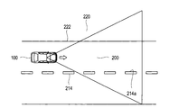
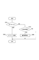
- FIG. 4 there is no white line on the left side that is one end side of both sides in the width direction of the traveling path 200 with respect to the host vehicle 100, and the boundary between the pavement surface suitable for traveling and the portion 220 inappropriate for traveling Is detected as the suitability boundary 222 of the travel path 200 defined by the suitability of travel.
- the inner end 210a of the white line 210 and the suitability boundary 222 are sometimes collectively referred to as a boundary.
- a boundary between the pavement surface and a portion unsuitable for driving is detected as a proper boundary on both sides in the width direction of the road. .
- the boundary between the pavement surface and a portion unsuitable for traveling is an appropriate boundary on the right side that is one end side on both sides in the width direction of the traveling path on which the host vehicle 100 travels.
- the suitability boundary 222 between the paved surface and the portion 220 unsuitable for traveling is recognized, for example, when the boundary detection unit 12 or the object detection unit 16 analyzes the image data.
- the right boundary at both ends in the width direction of the travel path 200 is defined by the inner end 214 a of the center line 214.
- a boundary between the portion suitable for traveling of the host vehicle 100 and the portion 220 inappropriate for traveling on the end side is defined.
- the suitability boundary 222 of the travel path 200 defined by the suitability of travel is used.
- the portion suitable for traveling of the host vehicle 100 is a paved surface or a road surface that is flat enough to allow the host vehicle 100 to travel even if it is not paved.
- the portion 220 unsuitable for traveling of the host vehicle 100 is a portion in which the host vehicle 100 cannot travel due to a structure such as a wall, a building, a guardrail, a lane defining a lane, a groove, a step, a cliff, or sand, or is difficult to travel. That is.
- the boundary detection unit 12 detects the width of the traveling road 200 in addition to detecting the boundary of the traveling road 200. Further, the boundary detection unit 12 detects the coordinates of the boundary of the traveling road 200 within the range of the captured image captured by the camera 54. Then, the boundary detection unit 12 calculates the curvature of the travel path 200 based on the coordinates of the boundary. The boundary detection unit 12 may acquire the curvature of the travel path 200 based on map information of a navigation device (not shown).
- the boundary detection unit 12 detects, for example, the boundary of the traveling road 200 or the lateral position of the host vehicle 100 with respect to the center line as the reference point of the traveling road 200 based on the image data. If the boundary detection unit 12 cannot detect the boundary of the travel path 200 in S20, the process proceeds to S230, and the departure avoidance unit 24 stops the departure avoidance control that avoids the own vehicle 100 deviating outside the travel path 200. Is commanded to the traveling control device 30, and this process is terminated. Instructing the travel control device 30 to stop the departure avoidance control includes continuing the current travel control when the travel control device 30 is not executing the departure avoidance control.
- the boundary detection unit 12 determines that the boundary of the traveling road cannot be detected.
- the process proceeds to S30, and the generation control unit 22 generates an image indicating the recognition state of the white line as one aspect of the boundary, and displays the generated image on the display 40. .
- the generation control unit 22 displays the white line icon 71 that is an image prepared in advance on the display 40 as shown in FIG. 5A.
- an image different from the white line icon 71 such as a line segment thinner than the white line icon 71 is displayed on the display 40 for the unrecognized white line icon 71, for example.
- the generation control unit 22 generates an image indicating the recognition state of the white line on the right side of the host vehicle and an image indicating the recognition state of the left side of the host vehicle separately on the left and right sides and displays them on the display 40.
- the image displayed on the display 40 is a position image indicating the position of the white line or the position of the object.
- the departure prediction unit 14 determines whether or not the own vehicle 100 has departed depending on whether or not the own vehicle 100 has reached a control start position at which the departure avoiding unit 24 causes the travel control device 30 to start departure avoidance control. Determine whether or not.
- the timing at which the traveling control device 30 starts the departure avoidance control is defined by the control start position.
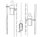
- the control start position is obtained from the map as a distance from the boundary on the departure side to the inside of the travel path 200, using the lateral speed of the host vehicle 100, the curvature of the travel path 200, the width of the travel path 200, etc. as parameters.
- reference numeral 300 indicates the control start position.
- the departure prediction unit 14 predicts that the host vehicle 100 reaches the control start position 300 and departs from the travel path 200.
- the control start position 300 indicates a position at which the host vehicle 100 reaches the boundary of the travel path in a preset arrival time when the host vehicle 100 moves from the control start position 300 at the current lateral speed, for example.
- the process proceeds to S230, and the departure avoidance unit 24 causes the travel control device 30 to stop the departure avoidance control, and this process is terminated.
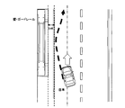
- the departure prediction unit 14 predicts that the host vehicle 100 will depart outside the travel path 200. In this case, in the processes of S50 and S60, the departure prediction unit 14 determines whether or not an object exists on the departure side boundary or outside the boundary.
- the process proceeds to S70 described later. If there is an object on or outside the boundary on the departure side in S50, the process proceeds to S60, and the departure prediction unit 14 determines the distance between the object and the boundary of the travel path, that is, how far the object is from the boundary. Determine if they are outside. That is, the departure prediction unit 14 determines whether or not the distance between the object and the boundary is equal to or greater than the allowable distance that the host vehicle 100 may deviate outside the boundary when there is no object outside the boundary or the boundary. judge. In this embodiment, the allowable distance is set to 45 cm.
- the process proceeds to S70.
- the object parameter recognition unit 20 determines whether or not the detected boundary on the departure side of the travel path 200 is a white line.
- the white line includes a center line and a yellow line.
- the process proceeds to S80.
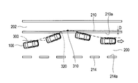
- the object parameter recognition unit 20 sets a command value to be instructed to the travel control device 30 in order to avoid the departure of the host vehicle 100. For example, as shown in FIG. 6, the object parameter recognizing unit 20 sets the target position 310 of the maximum movement position where the own vehicle 100 moves most on the departure side on the departure side from the departure side boundary on the departure side.
- the distance D is set to +30 cm from the inner end 210a of the white line 210.
- the process proceeds to S240.
- the plus sign of +30 cm indicates that it is outside the traveling road 200 from the inner end 210a of the white line 210 on the departure side.
- the object parameter recognition unit 20 sets a command value to be instructed to the travel control device 30 in order to avoid the departure of the host vehicle 100. For example, as shown in FIG. 7, the object parameter recognition unit 20 sets the target position 310 of the maximum movement position to a distance D of “boundary ⁇ L3 cm” with respect to the suitability boundary 222 on the departure side.
- the process proceeds to S240.
- L3 is a positive value, it indicates that the set target position 310 is inside the traveling path 200 from the suitability boundary 222 on the departure side.
- L3 cm is set to 5 cm, for example.
- the process proceeds to S120, and the object detection unit 16 determines whether or not the object is a vehicle.
- the object parameter recognizing unit 20 is a parked vehicle representing a vehicle in which the vehicle is parked, a parallel running vehicle that runs in the same direction as the own vehicle, and a direction opposite to the own vehicle. It is determined based on the relative speed between the host vehicle and the object.
- the process proceeds to S130, and the generation control unit 22 reads the vehicle icon 72, which is a picture representing the vehicle, from the memory, and displays the image on the display 40. Specifically, as illustrated in FIG. 5A, the generation control unit 22 arranges the vehicle icon 72 at a position corresponding to the positional relationship with a boundary such as a white line, and sets the relative movement direction of the vehicle around the vehicle icon 72. An arrow image 73 is displayed. In the arrow image, the direction indicated by the arrow indicates the relative movement direction of the vehicle.
- the image example shown in FIG. 5A shows a situation in which a vehicle having a higher speed than the host vehicle is running in parallel on the adjacent traveling path adjacent to the traveling path of the host vehicle, as shown in FIG. 5B.
- the image shown in FIG. 5A can represent the recognition state of the white line, the relationship of the position of the object with respect to the position of the white line, the relative movement direction of the object, the type of the object, and the like.
- the object parameter recognizing unit 20 sets a command value to be instructed to the travel control device 30 in order to avoid deviation of the host vehicle 100.
- the object parameter recognition unit 20 sets the target position 310 of the maximum movement position to the distance D of “boundary ⁇ L2 cm” with the inner end 210a of the departure-side white line 210 as a boundary, and the process proceeds to S240.
- L2 is a positive value, and L1> L2> L3.
- L2 cm is set to 10 cm, for example.
- the boundary display process is a process of displaying an image according to the type of the object when the type of the object is other than a vehicle or a pedestrian.
- the object parameter recognition unit 20 determines whether or not the detected object is a guardrail. If the object is a guard rail in S310, the process proceeds to S320. In S320, the generation control unit 22 displays an image indicating the guardrail on the display 40, and ends the boundary display process.
- FIG. 9B As an image showing the guardrail, for example, as shown in FIG. 9B, when a white line and a guardrail are detected on one side of the vehicle, an image including both icons indicating these is generated as shown in FIG. 9A. You may make it display.
- the white line icon 71 is displayed on the right side of the host vehicle, the white line is recognized on the left side, and the in-control icon 78 indicating that departure avoidance control is being performed, and the guardrail icon 82 indicating the guardrail. Is displayed.
- the process proceeds to S330, and the object parameter recognition unit 20 determines whether or not the object is another three-dimensional object.
- the other three-dimensional object indicates a portion 220 that is not suitable for the traveling of the host vehicle 100 described above.
- S330 if the object is another three-dimensional object, the process proceeds to S340.
- the generation control unit 22 displays an image indicating the suitability boundary 222 on the display 40, and then ends the boundary display process.
- the generation control unit 22 displays a suitability boundary icon 83 indicating the suitability boundary 222. If the object is not another three-dimensional object in S330, the boundary display process ends.
- the object parameter recognition unit 20 sets a command value to be instructed to the travel control device 30 in order to avoid the departure of the host vehicle 100.
- the object parameter recognition unit 20 sets the target position 310 of the maximum movement position with respect to the boundary between the traveling path 200 and the pole 230 as a distance D of “boundary ⁇ L3 cm”. Subsequently, the process proceeds to S240.
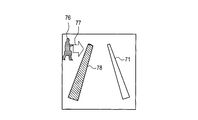
- the generation control unit 22 causes the display 40 to display an image indicating a pedestrian.
- the image indicating the pedestrian displays a pedestrian icon 76 that is a picture prepared in advance as an image indicating the pedestrian in the memory.
- an arrow icon 77 indicating the moving direction of the pedestrian is also displayed.
- the pedestrian icon 76 is displayed together with the white line icon 71 in this way only when a person such as a pedestrian is located within 45 cm from the white line as shown in FIG. 11B, for example. This is because only the person necessary for the control is displayed as the pedestrian icon 76.
- pattern matching using a pedestrian dictionary for estimating the direction of movement from the shape of the pedestrian is performed, or images are tracked in time series. .
- the generation control unit 22 performs a display during control.
- the display during control is a display indicating that departure avoidance control is being performed.
- an in-control icon 78 in which the deviation-side white line icon 71 among the left and right white line icons 71 is highlighted is displayed.
- the in-control icon 78 shows a white line on the left side which is the departure side in FIG. 12, and the white line icon 71 is devised so as to attract the driver's attention by changing the color or blinking.
- the object parameter recognizing unit 20 sets a command value to be instructed to the travel control device 30 in order to avoid the departure of the host vehicle 100.
- the object parameter recognition unit 20 sets the target position 310 of the maximum movement position to a distance D of “boundary ⁇ L1 cm” with the inner end 210a of the departure-side white line 210 as a boundary.
- the process proceeds to S240.
- L1 is a positive value, and L1> L3.
- L1 cm is set to 15 cm, for example.
- the departure avoidance unit 24 instructs the travel control device 30 to set a target line 320 on which the host vehicle 100 travels during the departure avoidance process.
- the travel control device 30 performs deviation avoidance control by feedback-controlling energization to the steering motor 32 so that the host vehicle 100 travels on the commanded target line 320.
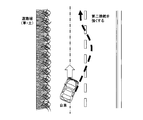
- the departure avoidance unit 24 performs offset control to move the lateral position where the host vehicle travels on the travel path to the far side from the person when a person is detected within a predetermined distance from the white line.
- the generation control unit 22 displays an offset icon 79 indicating that the offset control is being performed. For example, when a pedestrian is detected on the left side of the travel path, the travel position is offset to the right by about 20 cm in the width direction.
- the generation control unit 22 displays a down arrow icon 74 representing the approach of the vehicle together with the vehicle icon 72A. 40.
- the vehicle icon 72A to be displayed is an icon indicating an oncoming vehicle, and is set to a color different from the vehicle icon 72 indicating a parallel running vehicle, for example.
- the vehicle icon 72 indicating a parallel running vehicle and the vehicle icon 72A indicating an oncoming vehicle may be set to different patterns.
- the boundary detection unit 12 acquires the position of the boundary that defines both ends in the width direction of the travel path on which the host vehicle travels, and the object detection unit 16 Acquires the position of surrounding objects.
- the generation control unit 22 generates a position image that is an image indicating the position of the boundary and the position of the object, and causes the display device to display the position image.
- the departure avoidance apparatus 10 of the departure avoidance system 2 is configured to include an image indicating whether or not the position of the boundary portion has been acquired as the position image. According to such a departure avoidance system 2, it is possible to make the occupant recognize whether or not the position of the boundary portion has been acquired.
- the position of the boundary portion is acquired for each of the right side and the left side of the traveling path, and the boundary portion positioned on the right side of the traveling path and the position of the traveling path are obtained as position images.
- the boundary part located in the left side it is comprised so that the image which shows whether each position has been acquired can be included.
- the departure avoidance device 10 of the departure avoidance system 2 is configured to recognize the moving direction of an object and include an image indicating the moving direction of the object as a position image.
- the departure avoidance apparatus 10 of the departure avoidance system 2 is configured to recognize the type of an object and represent the position of the object using an image indicating the type of the object.
- the departure avoidance device 10 of the departure avoidance system 2 recognizes the relative speed between the host vehicle and the object, recognizes whether the object is a vehicle, and recognizes the recognition when the object is a vehicle. Based on the relative speed, the vehicle is recognized as a parallel vehicle traveling in the same direction as the own vehicle or a non-parallel vehicle traveling in a different direction from the own vehicle. If the recognized vehicle is a parallel vehicle, an image indicating a parallel vehicle is generated. If the recognized vehicle is a non-parallel vehicle, a non-parallel vehicle different from the image indicating the parallel vehicle is generated.
- the position image is configured to include an image indicating a parallel running vehicle or a non-parallel running vehicle.
- the departure avoidance device 10 of the departure avoidance system 2 recognizes whether or not the object is a person, and when recognizing the person, generates an image showing the pedestrian and displays the pedestrian as a position image. It is comprised so that the image shown may be included.
- the departure avoidance apparatus 10 of the departure avoidance system 2 is configured to generate a position image by combining an object icon indicating an object with a pattern and a boundary icon indicating a boundary portion with a pattern.
- the departure avoidance device 10 of the departure avoidance system 2 is configured to acquire a recognition result of a suitability boundary representing a boundary between an unsuitable portion 220 representing a portion unsuitable for traveling of the host vehicle and a travel path as a boundary portion. Has been.
- a boundary with a portion unsuitable for traveling of the host vehicle can be acquired as a proper boundary.
- the departure avoidance apparatus 10 of the departure avoidance system 2 it is predicted that the own vehicle deviates from the traveling road based on the traveling state of the own vehicle traveling on the traveling road defined by the boundary portion. Then, when the own vehicle deviates from the traveling road, the departure prediction unit predicts, and when the own vehicle departs from the traveling road or an object exists outside the boundary portion, the own vehicle moves to the deviating side.
- the travel control device that controls the travel state is instructed so that the maximum movement position of the vehicle is on the inner side of the travel path than when the vehicle is deviating from the travel path or on the outer side of the boundary. Thus, the host vehicle is prevented from deviating from the travel path.
- the inside indicates a direction approaching a position where the host vehicle should travel in a lateral position in the travel path.
- the object is positioned around the boundary portion of the traveling road, and the traveling track of the vehicle by the control that suppresses the departure from the traveling road is changed to be more inside the traveling road. At this time, it is possible to notify the occupant of performing such control by displaying the position image.
- the second embodiment is different from the first embodiment in that the image display mode is set in consideration of the driver's psychological pressure, in other words, the psychological margin, in the departure avoidance process.
- the departure avoidance process executed by the departure avoidance apparatus 10 of the second embodiment instead of the departure avoidance process of the first embodiment shown in FIG. 2 will be described with reference to the flowchart of FIG.
- the process of S410 is performed following the process of S10, and the psychological pressure is calculated in the process of S410.
- Psychological pressure is a numerical value of how much fear the driver of the own vehicle feels about the presence of another vehicle. In order to calculate the psychological pressure, for example, a distance from an object such as another vehicle and a vehicle speed that is the speed of the host vehicle are used.
- a map is used in which the vertical axis represents the distance in the traveling direction of the host vehicle, and the horizontal axis represents the vehicle speed of the host vehicle.
- This map shows that the psychological pressure increases as the vertical distance decreases and the vehicle speed increases.
- a threshold is provided at a position where the vertical distance is 15 m until the vehicle speed is 40 km / h, and a threshold is provided so that the vertical distance increases as the vehicle speed increases when the vehicle speed is 40 km / h or higher.
- the psychological pressure increases as the distance to the line segment indicated by the threshold increases. Set to increase the degree of pressure. However, it is assumed that there is no psychological pressure in the area above the line segment indicated by the threshold in the map.
- a display mode for displaying the vehicle on the display 40 is set.
- the display mode is set using a map that sets the display mode based on the relative speed with the other vehicle and the calculated psychological pressure. That is, as shown in FIG. 17, the display mode is set according to whether the position on the map specified by the relative speed and the psychological pressure is an area that displays highlighting or an area that performs normal display. In the example shown in FIG. 17, an object with a small relative speed is set to be easily highlighted.
- the flashing vehicle icon 81 is set to be displayed.
- the display method is not limited to blinking, and may be any display method that attracts the driver's attention as compared to the normal vehicle icon 72, such as changing the color.
- the degree of psychological pressure felt by the driver of the host vehicle is estimated, and the display mode of the image is changed according to the degree of psychological pressure.
- the icon indicating the vehicle blinks or the display color is changed to a color that calls attention (for example, yellow or red)
- the driver is alerted by changing the display mode.
- the departure avoidance device 10 is configured to change the distance between the object icon and the boundary icon in the position image as the distance based on the acquired object position and boundary position increases. May be.
- the object icon is an icon indicating an object such as a vehicle or a pedestrian
- the boundary icon is an icon indicating a white line or a suitability boundary.
- the vehicle icon 72 when the detected vehicle is on the white line, the vehicle icon 72 is displayed over the white line icon 71. Further, as shown in FIG. 19B, when the detected vehicle travels about 30 cm from the white line, the vehicle icon 72 is displayed slightly apart from the white line icon 71. Further, as shown in FIG. 19C, when the detected vehicle travels a position about 30 cm or more away from the white line, the vehicle icon 72 is displayed farther from the white line icon 71 than in the case shown in FIG. 19B.
- the distance between the object icon and the boundary icon can be expressed by the position image.
- the departure avoidance device 10 may be configured to generate an image indicating the distance between the object and the boundary portion as a numerical value, and include an image indicating the distance as a numerical value as the position image. For example, as shown in FIG. 20, a numerical icon 85 indicating the distance between the white line and the vehicle may be displayed between the white line icon 71 and the vehicle icon 72.
- the distance between the object and the boundary portion in the position image can be recognized numerically.
- the functions of one component in the above embodiment may be distributed as a plurality of components, or the functions of a plurality of components may be integrated into one component. Moreover, you may abbreviate
- non-transitional actual records such as a device serving as a component of the departure avoidance system, a program for causing a computer to function as the departure avoidance system, and a semiconductor memory storing the program
- the present invention can also be realized in various forms such as a medium and a deviation avoidance method.
- the deviation avoidance device 10 corresponds to a display control device according to the present invention
- the boundary detection unit 12 corresponds to a boundary acquisition unit according to the present invention
- the object detection unit 16 corresponds to an object acquisition unit referred to in the present invention
- the object parameter recognition unit 20 includes a movement recognition unit, an object type recognition unit, and a relative speed recognition unit referred to in the present invention. It corresponds to.
- the boundary acquisition unit (12) acquires the position of the boundary part that defines both ends in the width direction of the travel path (200) on which the host vehicle travels, and the object acquisition unit (16). Acquires the position of an object located around the road.
- the generation control unit (22) generates a position image that is an image indicating the position of the boundary and the position of the object, and displays the position image on the display device.
Landscapes
- Physics & Mathematics (AREA)
- General Physics & Mathematics (AREA)
- Traffic Control Systems (AREA)
Abstract
A display control device according to the present invention is installed on a current vehicle, displays an image on a display device that a passenger of the vehicle views, comprises a border obtaining unit that obtains the position of border sections defining both widthwise edges of a track that the vehicle is travelling and an object obtaining unit that obtains the position of objects located surrounding the track, generates a position image that is an image indicating the position of the border sections and the position of the objects and displays the position image on the display device.
Description
本発明は、自車両の乗員が視認する表示装置に画像を表示させる表示制御装置、および自車両を制御する車両制御装置に関する。
The present invention relates to a display control device that displays an image on a display device visually recognized by a passenger of the host vehicle, and a vehicle control device that controls the host vehicle.
上記表示制御装置として、例えば、特許文献1に示すように、走行路の境界となる白線を認識し、白線の認識状態を画像で表示させるものが知られている。
As the display control device, for example, as shown in Patent Document 1, a device that recognizes a white line as a boundary of a traveling road and displays a recognition state of the white line as an image is known.
上記表示制御装置においては、乗員が画像を見るだけで多くのことを認識できるようにすることに対する要求がある。
In the above display control device, there is a demand for enabling the occupant to recognize many things only by looking at the image.
一実施形態は、自車両の乗員が視認する表示装置に画像を表示させる表示制御装置において、より多くの事項を表示可能とする。
実施形態の表示制御装置は、自車両に搭載され、前記自車両の乗員が視認する表示装置に画像を表示させる表示制御装置であって、前記自車両が走行する走行路の幅方向両端を規定する境界部の位置を取得する境界取得部と、前記走行路の周囲に位置する物体の位置を取得する物体取得部と、前記境界部の位置および前記物体の位置を示す画像である位置画像を生成し、該位置画像を前記表示装置に表示させる。 In one embodiment, more items can be displayed in a display control device that displays an image on a display device visually recognized by a passenger of the host vehicle.
The display control device of the embodiment is a display control device that is mounted on a host vehicle and displays an image on a display device that is visually recognized by an occupant of the host vehicle, and defines both ends in the width direction of a traveling path on which the host vehicle travels. A boundary acquisition unit that acquires a position of the boundary part, an object acquisition unit that acquires a position of an object located around the travel path, and a position image that is an image showing the position of the boundary part and the position of the object The position image is generated and displayed on the display device.
以下、本発明の実施形態を図面に基づいて説明する。
[1.第1実施形態]
[1-1.構成]
本発明が適用された逸脱回避システム2は、乗用車等の車両に搭載されており、この車両が走行する走行路からの逸脱を抑制する機能を有する。なお、走行路とは、自車両が走行すべき領域の左右の端部を規定する境界部よりも自車両側の領域を示す。 Hereinafter, embodiments of the present invention will be described with reference to the drawings.
[1. First Embodiment]
[1-1. Constitution]
Thedeparture avoidance system 2 to which the present invention is applied is mounted on a vehicle such as a passenger car, and has a function of suppressing departure from a travel path on which the vehicle travels. In addition, a travel path shows the area | region on the own vehicle side rather than the boundary part which prescribes | regulates the right and left edge part of the area | region where the own vehicle should drive | work.
[1.第1実施形態]
[1-1.構成]
本発明が適用された逸脱回避システム2は、乗用車等の車両に搭載されており、この車両が走行する走行路からの逸脱を抑制する機能を有する。なお、走行路とは、自車両が走行すべき領域の左右の端部を規定する境界部よりも自車両側の領域を示す。 Hereinafter, embodiments of the present invention will be described with reference to the drawings.
[1. First Embodiment]
[1-1. Constitution]
The
本実施形態の逸脱回避システム2では、ディスプレイ40により多くの事項を表示させることによって、利便性を向上できるよう構成されている。なお、本実施形態では、「逸脱を抑制する」旨を「逸脱を回避する」とも表現する。
The deviation avoidance system 2 of the present embodiment is configured to improve convenience by displaying many items on the display 40. In the present embodiment, “suppressing deviation” is also expressed as “avoiding deviation”.
逸脱回避システム2は、図1に示すように、逸脱回避装置10と、走行制御装置30と、操舵用モータ32と、ディスプレイ40と、逸脱回避起動スイッチ50と、カメラ54と、加速度センサ56と、ヨーレートセンサ58と、操舵角センサ60と、車速センサ62と、トルクセンサ64と、を備えている。
As shown in FIG. 1, the departure avoidance system 2 includes a departure avoidance device 10, a travel control device 30, a steering motor 32, a display 40, a departure avoidance start switch 50, a camera 54, and an acceleration sensor 56. A yaw rate sensor 58, a steering angle sensor 60, a vehicle speed sensor 62, and a torque sensor 64.
逸脱回避装置10は、CPUと、RAM、ROM等のメモリとを備える周知のコンピュータである。逸脱回避装置10は、メモリに記憶されたプログラムにより後述する逸脱回避処理を実行する。また、このプログラムの実行により、プログラムに対応する方法が実行される。なお、逸脱回避装置10を構成するマイクロコンピュータの数は1つでも複数でもよい。
The deviation avoidance device 10 is a known computer including a CPU and a memory such as a RAM and a ROM. The departure avoidance device 10 executes departure avoidance processing, which will be described later, by a program stored in the memory. Further, by executing this program, a method corresponding to the program is executed. The number of microcomputers constituting the departure avoidance device 10 may be one or more.
以下では、逸脱回避装置10を搭載する車両を自車両とする。なお、メモリには、複数種類のアイコンが予め記録されている。アイコンとは、物事を簡単な絵柄で記号化して表現したものを示し、具体的には、境界となる白線を示す画像、歩行者を示す画像、車両を示す画像、ガードレールを示す画像、後述する適否境界を示す画像等が含まれる。また、逸脱回避装置10を構成するこれらの要素を実現する手法はソフトウェアに限るものではなく、その一部または全部の要素を、論理回路やアナログ回路等を組み合わせたハードウェアを用いて実現してもよい。
Hereinafter, the vehicle on which the deviation avoidance device 10 is mounted is referred to as the own vehicle. A plurality of types of icons are recorded in advance in the memory. An icon represents a symbolized representation of things with a simple pattern. Specifically, an image showing a white line as a boundary, an image showing a pedestrian, an image showing a vehicle, an image showing a guardrail, which will be described later An image showing a suitability boundary is included. In addition, the method for realizing these elements constituting the deviation avoidance apparatus 10 is not limited to software, and some or all of the elements are realized by using hardware combining logic circuits, analog circuits, and the like. Also good.
逸脱回避装置10は、機能的に、境界検出部12と、逸脱予測部14と、物体検出部16と、指令値調整部18と、物体パラメータ認識部20と、生成制御部22と、逸脱回避部24と、を備えている。逸脱回避装置10の各部の機能は後述する。
The departure avoidance device 10 functionally includes a boundary detection unit 12, a departure prediction unit 14, an object detection unit 16, a command value adjustment unit 18, an object parameter recognition unit 20, a generation control unit 22, and a departure avoidance. Part 24. The function of each part of the deviation avoidance device 10 will be described later.
走行制御装置30は、ドライバがハンドルを操作する際の操舵トルクをトルクセンサ64から取得し、自車両100の車速を車速センサ62から取得する。そして、走行制御装置30は、操舵トルクと車速とに基づいて、ドライバによる操舵をアシストする操舵用モータ32が出力するアシストトルクを算出する。そして、走行制御装置30は、その算出結果に応じた通電量で操舵用モータ32を制御することにより、ドライバがハンドルを回す力のアシスト量を制御する。
The traveling control device 30 acquires the steering torque when the driver operates the steering wheel from the torque sensor 64, and acquires the vehicle speed of the host vehicle 100 from the vehicle speed sensor 62. Then, the travel control device 30 calculates the assist torque output by the steering motor 32 that assists the steering by the driver based on the steering torque and the vehicle speed. Then, the traveling control device 30 controls the assist amount of the force with which the driver turns the steering wheel by controlling the steering motor 32 with the energization amount according to the calculation result.
さらに、走行制御装置30は、走行している走行路から自車両が逸脱することを回避する場合、逸脱回避装置10からの指令により操舵用モータ32への通電量を制御して自車両の走行状態を制御する。操舵用モータ32は、自車両の進行方向を変更する操舵機構を駆動する操舵用アクチュエータに相当する。
Further, when the traveling control device 30 avoids the departure of the host vehicle from the traveling road, the traveling control device 30 controls the amount of current supplied to the steering motor 32 in accordance with a command from the departure avoiding device 10. Control the state. The steering motor 32 corresponds to a steering actuator that drives a steering mechanism that changes the traveling direction of the host vehicle.
走行制御装置30は、操舵用モータ32への通電制御だけでなく、図示しないブレーキシステムおよびパワートレインシステム等を制御することにより、自車両の走行状態を制御する。自車両の走行状態とは、自車両の前後方向および横方向の車速、走行路における横位置、前後方向および横方向の加速度等である。
The traveling control device 30 controls the traveling state of the host vehicle by controlling not only the power supply control to the steering motor 32 but also a brake system and a powertrain system (not shown). The traveling state of the host vehicle includes the vehicle speed in the front-rear direction and the lateral direction of the host vehicle, the lateral position on the travel path, the acceleration in the front-rear direction, the lateral direction, and the like.
逸脱回避起動スイッチ50は、例えばフロントパネルに設置されている。逸脱回避起動スイッチ50がオンになると、逸脱回避装置10が実行する逸脱回避処理が起動される。この際、逸脱回避支援を行う旨がディスプレイ40に表示される。なお、ディスプレイ40は、図示しないナビゲーション装置のディスプレイであってもよいし、逸脱回避処理用の専用のディスプレイであってもよい。
The departure avoidance start switch 50 is installed on the front panel, for example. When the departure avoidance start switch 50 is turned on, the departure avoidance process executed by the departure avoidance apparatus 10 is started. At this time, the display 40 displays that the departure avoidance support is performed. The display 40 may be a display of a navigation device (not shown) or a dedicated display for departure avoidance processing.
カメラ54は自車両100の前方を撮像するものである。逸脱回避装置10は、カメラ54が撮像した画像の画像データを解析する。加速度センサ56は自車両100の前後方向および横方向の加速度を検出する。ヨーレートセンサ58は自車両100の旋回角速度を検出する。
The camera 54 images the front of the host vehicle 100. The departure avoidance device 10 analyzes image data of an image captured by the camera 54. The acceleration sensor 56 detects the acceleration in the front-rear direction and the lateral direction of the host vehicle 100. The yaw rate sensor 58 detects the turning angular velocity of the host vehicle 100.
操舵角センサ60はハンドル(不図示)の操舵角を検出する。車速センサ62は自車両100の現在車速を検出する。トルクセンサ64は、ドライバがハンドルを操舵するときのトルクを検出する。
The steering angle sensor 60 detects the steering angle of a handle (not shown). The vehicle speed sensor 62 detects the current vehicle speed of the host vehicle 100. The torque sensor 64 detects torque when the driver steers the steering wheel.
[1-2.処理]
逸脱回避装置10が実行する逸脱回避処理について説明する。逸脱回避処理は、逸脱回避起動スイッチ50がオンになると所定の時間間隔で実行される。 [1-2. processing]
A departure avoidance process executed by thedeparture avoidance apparatus 10 will be described. The departure avoidance process is executed at predetermined time intervals when the departure avoidance activation switch 50 is turned on.
逸脱回避装置10が実行する逸脱回避処理について説明する。逸脱回避処理は、逸脱回避起動スイッチ50がオンになると所定の時間間隔で実行される。 [1-2. processing]
A departure avoidance process executed by the
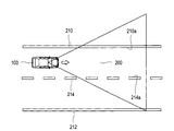
逸脱回避処理では、図2に示すように、まず、S10では、逸脱回避装置10は、各種パラメータを取得する。ここで、境界検出部12は、図3および図4に示すように、カメラ54が撮像した画像データから、自車両100が走行する走行路200の境界を検出する。また、物体検出部16は、画像データからこの画像データ内に含まれる物体の位置および種別を検出する。
In the departure avoidance process, as shown in FIG. 2, first, in S10, the departure avoidance apparatus 10 acquires various parameters. Here, as shown in FIGS. 3 and 4, the boundary detection unit 12 detects the boundary of the travel path 200 on which the host vehicle 100 travels from image data captured by the camera 54. Further, the object detection unit 16 detects the position and type of an object included in the image data from the image data.
例えば、物体検出部16は、カメラ54が撮像した撮像画像における物体の下端位置に基づいて自車両100と物体との距離を検出する。撮像画像において物体の下端位置が上になるほど、自車両100と物体との距離は遠いと判断できる。また、物体検出部16は、予め記憶されている物体モデルの辞書を用いたパターンマッチング等により物体の種類を決定する。
For example, the object detection unit 16 detects the distance between the host vehicle 100 and the object based on the lower end position of the object in the captured image captured by the camera 54. It can be determined that the distance between the host vehicle 100 and the object is farther as the lower end position of the object is higher in the captured image. The object detection unit 16 determines the type of the object by pattern matching using a dictionary of object models stored in advance.
また、物体パラメータ認識部20は、物体の位置および種別を時系列に従って追跡することによって、自車両に対する物体の相対移動ベクトルを認識する。また、物体パラメータ認識部20は、物体と走行路の境界との距離、つまり物体が境界からどの程度外側に離れているかを認識する。S10の処理では、これらの境界の位置、物体の位置や種別、相対移動ベクトル、物体と走行路の境界との距離等を、各種パラメータとして取得する。
Further, the object parameter recognition unit 20 recognizes the relative movement vector of the object with respect to the host vehicle by tracking the position and type of the object in time series. The object parameter recognition unit 20 also recognizes the distance between the object and the boundary between the traveling paths, that is, how far the object is away from the boundary. In the process of S10, the position of these boundaries, the position and type of the object, the relative movement vector, the distance between the object and the boundary of the travel path, and the like are acquired as various parameters.
続いて、S20では、境界検出部12は、自車両100が走行する走行路200の境界を検出できたか否かを判定する。走行路200の境界は、走行路200の幅方向両端を規定するものである。
図3では、道路の左右の白線210、212と道路の中央線214とのうち、左側の白線210の内側端210aと中央線214の内側端214aとaを走行路200の幅方向両端を規定する境界とする。白線210、212と道路の中央線214とは、例えば、画像データを解析することにより認識される。内側端210a、214aに限らず、白線210と中央線214の外側端等の予め設定した白線210および中央線214上の任意の位置を境界としてもよい。 Subsequently, in S20, theboundary detection unit 12 determines whether or not the boundary of the travel path 200 on which the host vehicle 100 travels has been detected. The boundary of the travel path 200 defines both ends of the travel path 200 in the width direction.
In FIG. 3, of the white lines 210 and 212 on the left and right of the road and the center line 214 of the road, the inner end 210 a of the left white line 210 and the inner end 214 a and a of the center line 214 are defined as both ends in the width direction of the travel path 200. Boundary. The white lines 210 and 212 and the road center line 214 are recognized, for example, by analyzing image data. Not only the inner ends 210a and 214a, but also arbitrary positions on the white line 210 and the center line 214 set in advance, such as the outer ends of the white line 210 and the center line 214, may be used as boundaries.
図3では、道路の左右の白線210、212と道路の中央線214とのうち、左側の白線210の内側端210aと中央線214の内側端214aとaを走行路200の幅方向両端を規定する境界とする。白線210、212と道路の中央線214とは、例えば、画像データを解析することにより認識される。内側端210a、214aに限らず、白線210と中央線214の外側端等の予め設定した白線210および中央線214上の任意の位置を境界としてもよい。 Subsequently, in S20, the
In FIG. 3, of the
図4では、自車両100に対して、走行路200の幅方向両側の一方の端部側である左側に白線が存在せず、走行に適した舗装面と走行に不適な部分220との境界が走行の適否により規定された走行路200の適否境界222として検出されている。なお、白線210の内側端210aと適否境界222とをまとめて、単に境界ということもある。
In FIG. 4, there is no white line on the left side that is one end side of both sides in the width direction of the traveling path 200 with respect to the host vehicle 100, and the boundary between the pavement surface suitable for traveling and the portion 220 inappropriate for traveling Is detected as the suitability boundary 222 of the travel path 200 defined by the suitability of travel. The inner end 210a of the white line 210 and the suitability boundary 222 are sometimes collectively referred to as a boundary.
白線が存在しない走行路として、例えば図4において中央線214のない走行路の場合には、走行路の幅方向両側において、舗装面と走行に不適な部分との境界が適否境界として検出される。
For example, in the case of a road having no central line 214 in FIG. 4 as a road having no white line, a boundary between the pavement surface and a portion unsuitable for driving is detected as a proper boundary on both sides in the width direction of the road. .
また、図4において右側通行をする場合には、自車両100が走行する走行路の幅方向両側の一方の端部側である右側において、舗装面と走行に不適な部分との境界が適否境界として検出される。
In addition, in the case of right-hand traffic in FIG. 4, the boundary between the pavement surface and a portion unsuitable for traveling is an appropriate boundary on the right side that is one end side on both sides in the width direction of the traveling path on which the host vehicle 100 travels. Detected as
舗装面と走行に不適な部分220との適否境界222は、例えば、境界検出部12または物体検出部16が画像データを解析することにより認識される。自車両100に対して、走行路200の幅方向両端の右側の境界は中央線214の内側端214aにより規定されている。
The suitability boundary 222 between the paved surface and the portion 220 unsuitable for traveling is recognized, for example, when the boundary detection unit 12 or the object detection unit 16 analyzes the image data. For the host vehicle 100, the right boundary at both ends in the width direction of the travel path 200 is defined by the inner end 214 a of the center line 214.
このように、走行路200の幅方向両端の少なくとも一方の端部側に白線が存在しない場合、自車両100の走行に適した部分と、端部側の走行に不適な部分220との境界を走行の適否により規定された走行路200の適否境界222とする。
As described above, when there is no white line on at least one end side of the both ends in the width direction of the travel path 200, a boundary between the portion suitable for traveling of the host vehicle 100 and the portion 220 inappropriate for traveling on the end side is defined. The suitability boundary 222 of the travel path 200 defined by the suitability of travel is used.
自車両100の走行に適した部分とは、舗装面あるいは舗装されていなくても自車両100が走行できる程度に平坦な整地された路面のことである。自車両100の走行に不適な部分220とは、壁、建物、ガードレール、車線を規定するポール、溝、段差、崖、砂地等の構造上自車両100が走行できないか、走行に困難が伴う部分のことである。
The portion suitable for traveling of the host vehicle 100 is a paved surface or a road surface that is flat enough to allow the host vehicle 100 to travel even if it is not paved. The portion 220 unsuitable for traveling of the host vehicle 100 is a portion in which the host vehicle 100 cannot travel due to a structure such as a wall, a building, a guardrail, a lane defining a lane, a groove, a step, a cliff, or sand, or is difficult to travel. That is.
境界検出部12は、走行路200の境界を検出することに加え、走行路200の幅を検出する。さらに、境界検出部12は、カメラ54が撮像する撮像画像の範囲内で走行路200の境界の座標を検出する。そして、境界検出部12は、境界の座標に基づいて走行路200の曲率を算出する。境界検出部12は、図示しないナビゲーション装置の地図情報に基づいて走行路200の曲率を取得してもよい。
The boundary detection unit 12 detects the width of the traveling road 200 in addition to detecting the boundary of the traveling road 200. Further, the boundary detection unit 12 detects the coordinates of the boundary of the traveling road 200 within the range of the captured image captured by the camera 54. Then, the boundary detection unit 12 calculates the curvature of the travel path 200 based on the coordinates of the boundary. The boundary detection unit 12 may acquire the curvature of the travel path 200 based on map information of a navigation device (not shown).
さらに、境界検出部12は、走行路200の基準点として、例えば走行路200の境界または中央線に対する自車両100の横位置等も画像データに基づいて検出する。
S20において、境界検出部12が走行路200の境界を検出できない場合、S230に移行し、逸脱回避部24は、自車両100が走行路200の外側に逸脱することを回避する逸脱回避制御の停止を走行制御装置30に指令し、本処理を終了する。走行制御装置30に逸脱回避制御の停止を指令することには、走行制御装置30が逸脱回避制御を実行中でない場合に現在の走行制御を継続させることも含める。 Further, theboundary detection unit 12 detects, for example, the boundary of the traveling road 200 or the lateral position of the host vehicle 100 with respect to the center line as the reference point of the traveling road 200 based on the image data.
If theboundary detection unit 12 cannot detect the boundary of the travel path 200 in S20, the process proceeds to S230, and the departure avoidance unit 24 stops the departure avoidance control that avoids the own vehicle 100 deviating outside the travel path 200. Is commanded to the traveling control device 30, and this process is terminated. Instructing the travel control device 30 to stop the departure avoidance control includes continuing the current travel control when the travel control device 30 is not executing the departure avoidance control.
S20において、境界検出部12が走行路200の境界を検出できない場合、S230に移行し、逸脱回避部24は、自車両100が走行路200の外側に逸脱することを回避する逸脱回避制御の停止を走行制御装置30に指令し、本処理を終了する。走行制御装置30に逸脱回避制御の停止を指令することには、走行制御装置30が逸脱回避制御を実行中でない場合に現在の走行制御を継続させることも含める。 Further, the
If the
例えば、白線が途切れているか、あるいは白線がない走行路において舗装面と非舗装面との境界を検出できない場合、境界検出部12は走行路の境界を検出できないと判定する。
For example, when the white line is interrupted or the boundary between the paved surface and the non-paved surface cannot be detected on the traveling road without the white line, the boundary detection unit 12 determines that the boundary of the traveling road cannot be detected.
S20において、走行路200の境界を検出できる場合、S30に移行し、生成制御部22は、境界の一態様である白線の認識状態を示す画像を生成し、生成した画像をディスプレイ40において表示させる。例えば、走行路における左右両側の白線を認識できている場合には、図5Aに示すように、生成制御部22は、予め準備された画像である白線アイコン71をディスプレイ40において表示させる。
In S20, when the boundary of the travel path 200 can be detected, the process proceeds to S30, and the generation control unit 22 generates an image indicating the recognition state of the white line as one aspect of the boundary, and displays the generated image on the display 40. . For example, when the white lines on both the left and right sides in the travel path can be recognized, the generation control unit 22 displays the white line icon 71 that is an image prepared in advance on the display 40 as shown in FIG. 5A.
なお、左右何れかの白線が認識できていない場合には、認識できていない側の白線アイコン71について、例えば、白線アイコン71よりも細い線分等、白線アイコン71とは異なる画像をディスプレイ40において表示させる。つまり、生成制御部22は、自車両よりも右側の白線の認識状態を示す画像、および自車両よりも左側の認識状態を示す画像を、左右別々に生成し、ディスプレイ40に表示させる。ディスプレイ40に表示される画像は、白線の位置や物体の位置を示す位置画像となる。
If the white line on either side is not recognized, an image different from the white line icon 71 such as a line segment thinner than the white line icon 71 is displayed on the display 40 for the unrecognized white line icon 71, for example. Display. That is, the generation control unit 22 generates an image indicating the recognition state of the white line on the right side of the host vehicle and an image indicating the recognition state of the left side of the host vehicle separately on the left and right sides and displays them on the display 40. The image displayed on the display 40 is a position image indicating the position of the white line or the position of the object.
続いて、S40において、逸脱予測部14は、逸脱回避部24が走行制御装置30に逸脱回避制御を開始させる制御開始位置に自車両100が到達したか否かにより、自車両100が逸脱するか否かを判定する。制御開始位置により、走行制御装置30が逸脱回避制御を開始するタイミングが規定される。
Subsequently, in S40, the departure prediction unit 14 determines whether or not the own vehicle 100 has departed depending on whether or not the own vehicle 100 has reached a control start position at which the departure avoiding unit 24 causes the travel control device 30 to start departure avoidance control. Determine whether or not. The timing at which the traveling control device 30 starts the departure avoidance control is defined by the control start position.
制御開始位置は、自車両100の横速度、走行路200の曲率、走行路200の幅等をパラメータとして、例えば逸脱側の境界から走行路200の内側に向かう距離としてマップから求める。
The control start position is obtained from the map as a distance from the boundary on the departure side to the inside of the travel path 200, using the lateral speed of the host vehicle 100, the curvature of the travel path 200, the width of the travel path 200, etc. as parameters.
例えば図6では、符号300が制御開始位置を示している。自車両100の逸脱側の前輪の外側端が制御開始位置300に到達すると、逸脱予測部14は、自車両100が制御開始位置300に到達し走行路200から逸脱すると予測する。制御開始位置300は、例えば現在の横速度で自車両100が制御開始位置300から移動すると、予め設定された到達時間で自車両100が走行路の境界に到達する位置を示している。
For example, in FIG. 6, reference numeral 300 indicates the control start position. When the outer end of the front wheel on the departure side of the host vehicle 100 reaches the control start position 300, the departure prediction unit 14 predicts that the host vehicle 100 reaches the control start position 300 and departs from the travel path 200. The control start position 300 indicates a position at which the host vehicle 100 reaches the boundary of the travel path in a preset arrival time when the host vehicle 100 moves from the control start position 300 at the current lateral speed, for example.
S40にて、制御開始位置300に到達していない場合、S230に移行し、逸脱回避部24は走行制御装置30に逸脱回避制御を停止させ、本処理を終了する。
S40にて、制御開始位置300に自車両100が到達すると、逸脱予測部14は自車両100が走行路200の外側に逸脱すると予測する。この場合、S50,S60の処理にて、逸脱予測部14は、逸脱側の境界上または境界の外側に物体が存在するか否かを判定する。 If thecontrol start position 300 has not been reached in S40, the process proceeds to S230, and the departure avoidance unit 24 causes the travel control device 30 to stop the departure avoidance control, and this process is terminated.
When thehost vehicle 100 reaches the control start position 300 in S40, the departure prediction unit 14 predicts that the host vehicle 100 will depart outside the travel path 200. In this case, in the processes of S50 and S60, the departure prediction unit 14 determines whether or not an object exists on the departure side boundary or outside the boundary.
S40にて、制御開始位置300に自車両100が到達すると、逸脱予測部14は自車両100が走行路200の外側に逸脱すると予測する。この場合、S50,S60の処理にて、逸脱予測部14は、逸脱側の境界上または境界の外側に物体が存在するか否かを判定する。 If the
When the
S50にて、逸脱側の境界または境界の外側に物体が存在しない場合、後述するS70に移行する。また、S50にて、逸脱側の境界上または境界の外側に物体が存在する場合、S60に移行し、逸脱予測部14は、物体と走行路の境界との距離、つまり物体が境界からどの程度外側に離れているかを判定する。すなわち、逸脱予測部14は、物体と境界との距離が、境界または境界の外側に物体が存在しない場合に自車両100が境界の外側に逸脱してもよい許容距離以上であるか否かを判定する。本実施形態では、許容距離を45cmに設定している。
In S50, if there is no object on the boundary on the departure side or outside the boundary, the process proceeds to S70 described later. If there is an object on or outside the boundary on the departure side in S50, the process proceeds to S60, and the departure prediction unit 14 determines the distance between the object and the boundary of the travel path, that is, how far the object is from the boundary. Determine if they are outside. That is, the departure prediction unit 14 determines whether or not the distance between the object and the boundary is equal to or greater than the allowable distance that the host vehicle 100 may deviate outside the boundary when there is no object outside the boundary or the boundary. judge. In this embodiment, the allowable distance is set to 45 cm.
S60にて、物体と境界との距離が許容距離以上の場合、S70に移行する。S70において、物体パラメータ認識部20は、検出された走行路200の逸脱側の境界が白線であるか否かを判定する。この処理において、白線には中央線や黄線も含むものとする。
In S60, if the distance between the object and the boundary is greater than or equal to the allowable distance, the process proceeds to S70. In S <b> 70, the object parameter recognition unit 20 determines whether or not the detected boundary on the departure side of the travel path 200 is a white line. In this process, the white line includes a center line and a yellow line.
S70にて、境界が白線の場合、S80に移行する。S80では、物体パラメータ認識部20は、自車両100の逸脱を回避するために走行制御装置30に指令する指令値を設定する。例えば、図6に示すように、物体パラメータ認識部20は、自車両100が逸脱側の境界から走行路200の外側において、逸脱側に最も移動する最大移動位置の目標位置310を、逸脱側の白線210の内側端210aから+30cmの距離Dに設定する。
In S70, if the boundary is a white line, the process proceeds to S80. In S <b> 80, the object parameter recognition unit 20 sets a command value to be instructed to the travel control device 30 in order to avoid the departure of the host vehicle 100. For example, as shown in FIG. 6, the object parameter recognizing unit 20 sets the target position 310 of the maximum movement position where the own vehicle 100 moves most on the departure side on the departure side from the departure side boundary on the departure side. The distance D is set to +30 cm from the inner end 210a of the white line 210.
この処理が終了するとS240に移行する。なお、+30cmのプラス符号は、逸脱側の白線210の内側端210aから走行路200の外側であることを示している。
また、S70にて、境界が白線以外の場合、物体パラメータ認識部20は、自車両100の逸脱を回避するために走行制御装置30に指令する指令値を設定する。例えば、図7に示すように、物体パラメータ認識部20は、最大移動位置の目標位置310を、逸脱側の適否境界222に対し、「境界-L3cm」の距離Dに設定する。この処理が終了するとS240に処理を移行する。 When this process ends, the process proceeds to S240. In addition, the plus sign of +30 cm indicates that it is outside the travelingroad 200 from the inner end 210a of the white line 210 on the departure side.
In S70, when the boundary is other than the white line, the objectparameter recognition unit 20 sets a command value to be instructed to the travel control device 30 in order to avoid the departure of the host vehicle 100. For example, as shown in FIG. 7, the object parameter recognition unit 20 sets the target position 310 of the maximum movement position to a distance D of “boundary−L3 cm” with respect to the suitability boundary 222 on the departure side. When this process ends, the process proceeds to S240.
また、S70にて、境界が白線以外の場合、物体パラメータ認識部20は、自車両100の逸脱を回避するために走行制御装置30に指令する指令値を設定する。例えば、図7に示すように、物体パラメータ認識部20は、最大移動位置の目標位置310を、逸脱側の適否境界222に対し、「境界-L3cm」の距離Dに設定する。この処理が終了するとS240に処理を移行する。 When this process ends, the process proceeds to S240. In addition, the plus sign of +30 cm indicates that it is outside the traveling
In S70, when the boundary is other than the white line, the object
L3は正の値であるから、設定された目標位置310は逸脱側の適否境界222から走行路200の内側であることを示している。L3cmは例えば5cmに設定されている。
ところで、S60にて、物体と境界との距離が許容距離未満の場合には、S110に移行し、物体検出部16は物体が歩行者であるか否かを判定する。 Since L3 is a positive value, it indicates that theset target position 310 is inside the traveling path 200 from the suitability boundary 222 on the departure side. L3 cm is set to 5 cm, for example.
By the way, in S60, when the distance between the object and the boundary is less than the allowable distance, the process proceeds to S110, and theobject detection unit 16 determines whether or not the object is a pedestrian.
ところで、S60にて、物体と境界との距離が許容距離未満の場合には、S110に移行し、物体検出部16は物体が歩行者であるか否かを判定する。 Since L3 is a positive value, it indicates that the
By the way, in S60, when the distance between the object and the boundary is less than the allowable distance, the process proceeds to S110, and the
S110にて、物体が歩行者ではない場合、S120に移行し、物体検出部16は、物体が車両であるか否かを判定する。また、この際、物体パラメータ認識部20は、物体が車両である場合に、この車両が駐車している車両を表す駐車車両、自車両と同方向に走行する並走車両、自車両と逆方向に走行する対向車両のうちの何れであるかを、自車両と物体との相対速度に基づいて判定する。
In S110, when the object is not a pedestrian, the process proceeds to S120, and the object detection unit 16 determines whether or not the object is a vehicle. At this time, when the object is a vehicle, the object parameter recognizing unit 20 is a parked vehicle representing a vehicle in which the vehicle is parked, a parallel running vehicle that runs in the same direction as the own vehicle, and a direction opposite to the own vehicle. It is determined based on the relative speed between the host vehicle and the object.
S120において、物体が車両の場合、S130に移行し、生成制御部22は、車両を表す絵柄である車両アイコン72をメモリから読み出し、この画像をディスプレイ40に表示させる。詳細には、図5Aに示すように、生成制御部22は、車両アイコン72を、白線等の境界との位置関係に応じた位置に配置し、車両アイコン72の周囲に車両の相対移動方向を示す矢印画像73を表示させる。矢印画像においては、矢印が示す方向が車両の相対移動方向を示す。
In S120, when the object is a vehicle, the process proceeds to S130, and the generation control unit 22 reads the vehicle icon 72, which is a picture representing the vehicle, from the memory, and displays the image on the display 40. Specifically, as illustrated in FIG. 5A, the generation control unit 22 arranges the vehicle icon 72 at a position corresponding to the positional relationship with a boundary such as a white line, and sets the relative movement direction of the vehicle around the vehicle icon 72. An arrow image 73 is displayed. In the arrow image, the direction indicated by the arrow indicates the relative movement direction of the vehicle.
なお、図5Aに示す画像例は、図5Bに示すように、自車両の走行路に隣接する隣接走行路において自車両よりも速度が速い車両が並走している状況を示している。図5Aに示す画像では、白線の認識状態、白線の位置に対する物体の位置の関係、物体の相対移動方向、物体の種別等を表現できている。
Note that the image example shown in FIG. 5A shows a situation in which a vehicle having a higher speed than the host vehicle is running in parallel on the adjacent traveling path adjacent to the traveling path of the host vehicle, as shown in FIG. 5B. The image shown in FIG. 5A can represent the recognition state of the white line, the relationship of the position of the object with respect to the position of the white line, the relative movement direction of the object, the type of the object, and the like.
続いて、S140において、物体パラメータ認識部20は、自車両100の逸脱を回避するために走行制御装置30に指令する指令値を設定する。例えば、物体パラメータ認識部20は、最大移動位置の目標位置310を、逸脱側の白線210の内側端210aを境界として「境界-L2cm」の距離Dに設定し、S240に処理を移行する。L2は正の値であり、L1>L2>L3である。L2cmは例えば10cmに設定されている。
Subsequently, in S140, the object parameter recognizing unit 20 sets a command value to be instructed to the travel control device 30 in order to avoid deviation of the host vehicle 100. For example, the object parameter recognition unit 20 sets the target position 310 of the maximum movement position to the distance D of “boundary−L2 cm” with the inner end 210a of the departure-side white line 210 as a boundary, and the process proceeds to S240. L2 is a positive value, and L1> L2> L3. L2 cm is set to 10 cm, for example.
S120にて、物体が車両ではない場合、S150に移行し、境界表示処理を実施する。境界表示処理は、物体の種別が車両や歩行者以外である場合に、その物体の種別に応じた画像を表示させる処理である。
In S120, when the object is not a vehicle, the process proceeds to S150, and the boundary display process is performed. The boundary display process is a process of displaying an image according to the type of the object when the type of the object is other than a vehicle or a pedestrian.
境界表示処理では、図8に示すように、まず、S310にて、物体パラメータ認識部20は、検出された物体がガードレールであるか否かを判定する。S310にて、物体がガードレールであれば、S320に移行する。S320では、生成制御部22は、ガードレールを示す画像をディスプレイ40に表示させ、境界表示処理を終了する。
In the boundary display process, as shown in FIG. 8, first, in S310, the object parameter recognition unit 20 determines whether or not the detected object is a guardrail. If the object is a guard rail in S310, the process proceeds to S320. In S320, the generation control unit 22 displays an image indicating the guardrail on the display 40, and ends the boundary display process.
ガードレールを示す画像としては、例えば図9Bに示すように、車両の片側において白線およびガードレールが検出された場合には、図9Aに示すように、これらを示すアイコンの両方を含む画像を生成し、表示させるようにしてもよい。図9Aに示す例では、自車両の右側において白線アイコン71を表示させ、左側においては白線を認識し、かつ逸脱回避制御を実施している旨の制御中アイコン78、およびガードレールを示すガードレールアイコン82を表示させている。
As an image showing the guardrail, for example, as shown in FIG. 9B, when a white line and a guardrail are detected on one side of the vehicle, an image including both icons indicating these is generated as shown in FIG. 9A. You may make it display. In the example shown in FIG. 9A, the white line icon 71 is displayed on the right side of the host vehicle, the white line is recognized on the left side, and the in-control icon 78 indicating that departure avoidance control is being performed, and the guardrail icon 82 indicating the guardrail. Is displayed.
また、S310にて、検出された物体がガードレールでなければ、S330に移行し、物体パラメータ認識部20は、物体がその他の立体物であるか否かを判定する。その他の立体物とは、前述した自車両100の走行に不適な部分220を示す。
In S310, if the detected object is not a guardrail, the process proceeds to S330, and the object parameter recognition unit 20 determines whether or not the object is another three-dimensional object. The other three-dimensional object indicates a portion 220 that is not suitable for the traveling of the host vehicle 100 described above.
S330にて、物体がその他の立体物であれば、S340に移行する。S340では、生成制御部22は、適否境界222を示す画像をディスプレイ40に表示させ、その後、境界表示処理を終了する。
In S330, if the object is another three-dimensional object, the process proceeds to S340. In S340, the generation control unit 22 displays an image indicating the suitability boundary 222 on the display 40, and then ends the boundary display process.
適否境界222を表示させる状況としては、例えば、図10Bに示すように、例えば左側の道路端に草原等が存在する場合が考えられる。このような場合、図10Aに示すように、生成制御部22は、適否境界222を示す適否境界アイコン83を表示させる。また、S330にて、物体がその他の立体物でなければ、境界表示処理を終了する。
As a situation in which the suitability boundary 222 is displayed, for example, as shown in FIG. In such a case, as illustrated in FIG. 10A, the generation control unit 22 displays a suitability boundary icon 83 indicating the suitability boundary 222. If the object is not another three-dimensional object in S330, the boundary display process ends.
続いて、図2に戻り、S160にて、物体パラメータ認識部20は、自車両100の逸脱を回避するために走行制御装置30に指令する指令値を設定する。例えば、物体パラメータ認識部20は、走行路200とポール230との境界に対して最大移動位置の目標位置310を「境界-L3cm」の距離Dに設定する。続いて、S240に移行する。
Subsequently, returning to FIG. 2, in S160, the object parameter recognition unit 20 sets a command value to be instructed to the travel control device 30 in order to avoid the departure of the host vehicle 100. For example, the object parameter recognition unit 20 sets the target position 310 of the maximum movement position with respect to the boundary between the traveling path 200 and the pole 230 as a distance D of “boundary−L3 cm”. Subsequently, the process proceeds to S240.
ところで、S110にて、物体が歩行者110の場合、S210に移行する。S210では、生成制御部22は、歩行者を示す画像をディスプレイ40に表示させる。歩行者を示す画像は、例えば、図11Aに示すように、メモリ内に歩行者を示す画像として予め準備された絵柄である歩行者アイコン76を表示させる。なお、この際、歩行者の移動方向を示す矢印アイコン77も表示させる。
Incidentally, in S110, when the object is the pedestrian 110, the process proceeds to S210. In S210, the generation control unit 22 causes the display 40 to display an image indicating a pedestrian. For example, as shown in FIG. 11A, the image indicating the pedestrian displays a pedestrian icon 76 that is a picture prepared in advance as an image indicating the pedestrian in the memory. At this time, an arrow icon 77 indicating the moving direction of the pedestrian is also displayed.
このように歩行者アイコン76を白線アイコン71と共に表示させるのは、例えば図11Bに示すように、歩行者等の人物が白線から45cm以内に位置する場合に限る。制御に必要となる人物のみを歩行者アイコン76として表示させるためである。なお、歩行者の移動方向を認識する際には、歩行者の形状から移動方向を推定するための歩行者辞書を用いたパターンマッチングを実施したり、画像を時系列に従って追跡したりすることよる。
The pedestrian icon 76 is displayed together with the white line icon 71 in this way only when a person such as a pedestrian is located within 45 cm from the white line as shown in FIG. 11B, for example. This is because only the person necessary for the control is displayed as the pedestrian icon 76. When recognizing the direction of movement of a pedestrian, pattern matching using a pedestrian dictionary for estimating the direction of movement from the shape of the pedestrian is performed, or images are tracked in time series. .
続いて、S240では、生成制御部22は、制御中表示を行う。制御中表示とは、逸脱回避制御を実施している旨の表示である。この処理では、例えば、図12に示すように、左右の白線アイコン71のうちの逸脱側の白線アイコン71を強調表示した制御中アイコン78を表示させる。制御中アイコン78は、図12では逸脱側である左側の白線を示し、白線アイコン71に対して色を変えたり点滅させたりすることで運転者の注意を惹くよう工夫されている。
Subsequently, in S240, the generation control unit 22 performs a display during control. The display during control is a display indicating that departure avoidance control is being performed. In this process, for example, as shown in FIG. 12, an in-control icon 78 in which the deviation-side white line icon 71 among the left and right white line icons 71 is highlighted is displayed. The in-control icon 78 shows a white line on the left side which is the departure side in FIG. 12, and the white line icon 71 is devised so as to attract the driver's attention by changing the color or blinking.
続いて、S220にて、物体パラメータ認識部20は、自車両100の逸脱を回避するために走行制御装置30に指令する指令値を設定する。例えば、物体パラメータ認識部20は、最大移動位置の目標位置310を、逸脱側の白線210の内側端210aを境界として「境界-L1cm」の距離Dに設定する。続いて、S240に移行する。なお、L1は正の値であり、L1>L3である。L1cmは例えば15cmに設定されている。
Subsequently, in S220, the object parameter recognizing unit 20 sets a command value to be instructed to the travel control device 30 in order to avoid the departure of the host vehicle 100. For example, the object parameter recognition unit 20 sets the target position 310 of the maximum movement position to a distance D of “boundary−L1 cm” with the inner end 210a of the departure-side white line 210 as a boundary. Subsequently, the process proceeds to S240. L1 is a positive value, and L1> L3. L1 cm is set to 15 cm, for example.
続いて、S250にて、逸脱回避部24は、逸脱回避処理中に自車両100が走行する目標ライン320を走行制御装置30に指令する。走行制御装置30は、指令された目標ライン320を自車両100が走行するように、操舵用モータ32への通電をフィードバック制御して逸脱回避制御を実行する。
Subsequently, in S250, the departure avoidance unit 24 instructs the travel control device 30 to set a target line 320 on which the host vehicle 100 travels during the departure avoidance process. The travel control device 30 performs deviation avoidance control by feedback-controlling energization to the steering motor 32 so that the host vehicle 100 travels on the commanded target line 320.
なお、逸脱回避部24は、白線から所定距離以内に人物が検出された場合に、走行路内において自車両が走行する横位置を人物から遠い側に移動させるオフセット制御を実施する。この場合には、例えば、図13に示すように、生成制御部22は、オフセット制御を実施している旨を示すオフセットアイコン79を表示させる。例えば走行路の左側に歩行者を検知した場合、幅方向において走行位置を20cm程度右側にオフセットさせる。
The departure avoidance unit 24 performs offset control to move the lateral position where the host vehicle travels on the travel path to the far side from the person when a person is detected within a predetermined distance from the white line. In this case, for example, as illustrated in FIG. 13, the generation control unit 22 displays an offset icon 79 indicating that the offset control is being performed. For example, when a pedestrian is detected on the left side of the travel path, the travel position is offset to the right by about 20 cm in the width direction.
また、図14Bに示すように、検出された物体が対向車両である場合には、図14Aに示すように、生成制御部22は、車両アイコン72Aとともに車両の接近を表す下向き矢印アイコン74をディスプレイ40に表示させる。この際、表示させる車両アイコン72Aは、対向車両を示すアイコンであり、例えば、並走車両を示す車両アイコン72とは異なる色に設定される。なお、並走車両を示す車両アイコン72と対向車両を示す車両アイコン72Aとは、異なる絵柄に設定されてもよい。
As shown in FIG. 14B, when the detected object is an oncoming vehicle, as shown in FIG. 14A, the generation control unit 22 displays a down arrow icon 74 representing the approach of the vehicle together with the vehicle icon 72A. 40. At this time, the vehicle icon 72A to be displayed is an icon indicating an oncoming vehicle, and is set to a color different from the vehicle icon 72 indicating a parallel running vehicle, for example. The vehicle icon 72 indicating a parallel running vehicle and the vehicle icon 72A indicating an oncoming vehicle may be set to different patterns.
[1-3.効果]
以上詳述した第1実施形態によれば、以下の効果が得られる。
(1a)逸脱回避システム2の逸脱回避装置10において、境界検出部12は自車両が走行する走行路の幅方向両端を規定する境界部の位置を取得し、物体検出部16は、走行路の周囲に位置する物体の位置を取得する。また、生成制御部22は、境界部の位置および物体の位置を示す画像である位置画像を生成し、該位置画像を表示装置に表示させる。 [1-3. effect]
According to the first embodiment described in detail above, the following effects can be obtained.
(1a) In thedeparture avoidance device 10 of the departure avoidance system 2, the boundary detection unit 12 acquires the position of the boundary that defines both ends in the width direction of the travel path on which the host vehicle travels, and the object detection unit 16 Acquires the position of surrounding objects. In addition, the generation control unit 22 generates a position image that is an image indicating the position of the boundary and the position of the object, and causes the display device to display the position image.
以上詳述した第1実施形態によれば、以下の効果が得られる。
(1a)逸脱回避システム2の逸脱回避装置10において、境界検出部12は自車両が走行する走行路の幅方向両端を規定する境界部の位置を取得し、物体検出部16は、走行路の周囲に位置する物体の位置を取得する。また、生成制御部22は、境界部の位置および物体の位置を示す画像である位置画像を生成し、該位置画像を表示装置に表示させる。 [1-3. effect]
According to the first embodiment described in detail above, the following effects can be obtained.
(1a) In the
このような逸脱回避システム2によれば、位置画像において境界部の位置および物体の位置を示すので、乗員に境界部と物体との位置関係を良好に認識させることができる。すなわち、従来における境界部の位置を示す画像を表示させる技術と比較して、より多くの事項を表示可能とすることができる。
According to such a departure avoidance system 2, since the position of the boundary and the position of the object are shown in the position image, the occupant can be made to recognize the positional relationship between the boundary and the object well. That is, more items can be displayed as compared with the conventional technique of displaying an image indicating the position of the boundary portion.
(1b)逸脱回避システム2の逸脱回避装置10においては、位置画像として、境界部の位置が取得できたか否かを示す画像を含むよう構成されている。
このような逸脱回避システム2によれば、境界部の位置が取得できたか否かを乗員に認識させることができる。 (1b) Thedeparture avoidance apparatus 10 of the departure avoidance system 2 is configured to include an image indicating whether or not the position of the boundary portion has been acquired as the position image.
According to such adeparture avoidance system 2, it is possible to make the occupant recognize whether or not the position of the boundary portion has been acquired.
このような逸脱回避システム2によれば、境界部の位置が取得できたか否かを乗員に認識させることができる。 (1b) The
According to such a
(1c)逸脱回避システム2の逸脱回避装置10においては、走行路の右側および左側のそれぞれについて境界部の位置を取得し、位置画像として、走行路の右側に位置する境界部、および走行路の左側に位置する境界部について、それぞれの位置が取得できたか否かを示す画像を含むよう構成されている。
(1c) In the departure avoidance apparatus 10 of the departure avoidance system 2, the position of the boundary portion is acquired for each of the right side and the left side of the traveling path, and the boundary portion positioned on the right side of the traveling path and the position of the traveling path are obtained as position images. About the boundary part located in the left side, it is comprised so that the image which shows whether each position has been acquired can be included.
このような逸脱回避システム2によれば、境界部の位置が取得できたか否かを左右別々に乗員に認識させることができる。
(1d)逸脱回避システム2の逸脱回避装置10においては、物体の移動方向を認識し、位置画像として、物体の移動方向を示す画像を含むよう構成されている。 According to such adeparture avoidance system 2, it is possible to cause the occupant to recognize whether the position of the boundary portion has been acquired separately on the left and right.
(1d) Thedeparture avoidance device 10 of the departure avoidance system 2 is configured to recognize the moving direction of an object and include an image indicating the moving direction of the object as a position image.
(1d)逸脱回避システム2の逸脱回避装置10においては、物体の移動方向を認識し、位置画像として、物体の移動方向を示す画像を含むよう構成されている。 According to such a
(1d) The
このような逸脱回避システム2によれば、物体の移動方向を乗員に認識させることができる。
(1e)逸脱回避システム2の逸脱回避装置10においては、物体の種別を認識し、物体の種別を示す画像を用いて物体の位置を表すよう構成されている。 According to such adeparture avoidance system 2, it is possible to make the occupant recognize the moving direction of the object.
(1e) Thedeparture avoidance apparatus 10 of the departure avoidance system 2 is configured to recognize the type of an object and represent the position of the object using an image indicating the type of the object.
(1e)逸脱回避システム2の逸脱回避装置10においては、物体の種別を認識し、物体の種別を示す画像を用いて物体の位置を表すよう構成されている。 According to such a
(1e) The
このような逸脱回避システム2によれば、認識された物体の種別に応じた画像を表示するので、当該表示制御装置が認識した物体の種別を乗員に認識させることができる。
(1f)逸脱回避システム2の逸脱回避装置10においては、自車両と物体との相対速度を認識し、物体が車両であるか否かを認識するとともに、物体が車両である場合に、該認識した車両が自車両と同方向に走行する並走車または自車両と異なる方向に走行する非並走車であることを相対速度に基づいて認識する。そして、認識した車両が並走車である場合には並走車を示す画像を生成し、認識した車両が非並走車である場合には並走車を示す画像とは異なる非並走車を示す画像を生成し、位置画像として、並走車または非並走車を示す画像を含むよう構成されている。 According to such adeparture avoidance system 2, an image corresponding to the recognized object type is displayed, so that the occupant can recognize the object type recognized by the display control device.
(1f) Thedeparture avoidance device 10 of the departure avoidance system 2 recognizes the relative speed between the host vehicle and the object, recognizes whether the object is a vehicle, and recognizes the recognition when the object is a vehicle. Based on the relative speed, the vehicle is recognized as a parallel vehicle traveling in the same direction as the own vehicle or a non-parallel vehicle traveling in a different direction from the own vehicle. If the recognized vehicle is a parallel vehicle, an image indicating a parallel vehicle is generated. If the recognized vehicle is a non-parallel vehicle, a non-parallel vehicle different from the image indicating the parallel vehicle is generated. The position image is configured to include an image indicating a parallel running vehicle or a non-parallel running vehicle.
(1f)逸脱回避システム2の逸脱回避装置10においては、自車両と物体との相対速度を認識し、物体が車両であるか否かを認識するとともに、物体が車両である場合に、該認識した車両が自車両と同方向に走行する並走車または自車両と異なる方向に走行する非並走車であることを相対速度に基づいて認識する。そして、認識した車両が並走車である場合には並走車を示す画像を生成し、認識した車両が非並走車である場合には並走車を示す画像とは異なる非並走車を示す画像を生成し、位置画像として、並走車または非並走車を示す画像を含むよう構成されている。 According to such a
(1f) The
このような逸脱回避システム2によれば、物体が車両である場合に、車両の走行方向に応じて異なる画像を表示させることができる。よって、取得された物体が車両である旨およびその車両の進行方向を乗員に認識させることができる。
According to such a departure avoidance system 2, when the object is a vehicle, different images can be displayed according to the traveling direction of the vehicle. Therefore, it is possible to make the occupant recognize that the acquired object is a vehicle and the traveling direction of the vehicle.
(1g)逸脱回避システム2の逸脱回避装置10においては、物体が人物であるか否かを認識し、人物を認識した場合に、歩行者を示す画像を生成し、位置画像として、歩行者を示す画像を含むよう構成されている。
(1g) The departure avoidance device 10 of the departure avoidance system 2 recognizes whether or not the object is a person, and when recognizing the person, generates an image showing the pedestrian and displays the pedestrian as a position image. It is comprised so that the image shown may be included.
このような逸脱回避システム2によれば、取得された物体が人物である旨を乗員に認識させることができる。
(1h)逸脱回避システム2の逸脱回避装置10においては、物体を絵柄で示す物体アイコンと境界部を絵柄で示す境界アイコンとを組み合わせることによって位置画像を生成するよう構成されている。 According to such adeparture avoidance system 2, the occupant can recognize that the acquired object is a person.
(1h) Thedeparture avoidance apparatus 10 of the departure avoidance system 2 is configured to generate a position image by combining an object icon indicating an object with a pattern and a boundary icon indicating a boundary portion with a pattern.
(1h)逸脱回避システム2の逸脱回避装置10においては、物体を絵柄で示す物体アイコンと境界部を絵柄で示す境界アイコンとを組み合わせることによって位置画像を生成するよう構成されている。 According to such a
(1h) The
このような逸脱回避システム2によれば、予め準備されたアイコンを組み合わせるので、画像を生成する際の処理負荷を軽減することができる。
(1i)逸脱回避システム2の逸脱回避装置10においては、境界部として、自車両の走行に不適な部分を表す不適部220と走行路との境界を表す適否境界の認識結果を取得するよう構成されている。 According to such adeparture avoidance system 2, since the icons prepared in advance are combined, it is possible to reduce the processing load when generating an image.
(1i) Thedeparture avoidance device 10 of the departure avoidance system 2 is configured to acquire a recognition result of a suitability boundary representing a boundary between an unsuitable portion 220 representing a portion unsuitable for traveling of the host vehicle and a travel path as a boundary portion. Has been.
(1i)逸脱回避システム2の逸脱回避装置10においては、境界部として、自車両の走行に不適な部分を表す不適部220と走行路との境界を表す適否境界の認識結果を取得するよう構成されている。 According to such a
(1i) The
このような逸脱回避システム2によれば、幅方向両端が厳密に規定されない場合であっても、自車両の走行に不適な部分との境界を適否境界として取得することができる。
(1j)逸脱回避システム2の逸脱回避装置10においては、境界部により規定される走行路を走行する自車両の走行状態に基づいて、自車両が走行路から逸脱することを予測する。そして、自車両が走行路から逸脱すると逸脱予測部が予測し、かつ自車両が走行路から逸脱する側の境界部または境界部の外側に物体が存在する際に、自車両が逸脱側へ移動する最大移動位置が、自車両が走行路から逸脱する側の境界部または境界部の外側に物体が存在しない際よりも走行路の内側になるように、走行状態を制御する走行制御装置に指令して自車両が走行路から逸脱することを抑制する。なお、内側とは、走行路内の横位置において自車両が走行すべき位置に近づく方向を示す。 According to such adeparture avoidance system 2, even if both ends in the width direction are not strictly defined, a boundary with a portion unsuitable for traveling of the host vehicle can be acquired as a proper boundary.
(1j) In thedeparture avoidance apparatus 10 of the departure avoidance system 2, it is predicted that the own vehicle deviates from the traveling road based on the traveling state of the own vehicle traveling on the traveling road defined by the boundary portion. Then, when the own vehicle deviates from the traveling road, the departure prediction unit predicts, and when the own vehicle departs from the traveling road or an object exists outside the boundary portion, the own vehicle moves to the deviating side. The travel control device that controls the travel state is instructed so that the maximum movement position of the vehicle is on the inner side of the travel path than when the vehicle is deviating from the travel path or on the outer side of the boundary. Thus, the host vehicle is prevented from deviating from the travel path. In addition, the inside indicates a direction approaching a position where the host vehicle should travel in a lateral position in the travel path.
(1j)逸脱回避システム2の逸脱回避装置10においては、境界部により規定される走行路を走行する自車両の走行状態に基づいて、自車両が走行路から逸脱することを予測する。そして、自車両が走行路から逸脱すると逸脱予測部が予測し、かつ自車両が走行路から逸脱する側の境界部または境界部の外側に物体が存在する際に、自車両が逸脱側へ移動する最大移動位置が、自車両が走行路から逸脱する側の境界部または境界部の外側に物体が存在しない際よりも走行路の内側になるように、走行状態を制御する走行制御装置に指令して自車両が走行路から逸脱することを抑制する。なお、内側とは、走行路内の横位置において自車両が走行すべき位置に近づく方向を示す。 According to such a
(1j) In the
このような逸脱回避システム2によれば、走行路の境界部の周囲に物体が位置し、走行路から逸脱することを抑制する制御による車両の走行軌道がより走行路の内側になるよう変更する際に、そのような制御を行うことを位置画像の表示により乗員に通知することができる。
According to the departure avoidance system 2 as described above, the object is positioned around the boundary portion of the traveling road, and the traveling track of the vehicle by the control that suppresses the departure from the traveling road is changed to be more inside the traveling road. At this time, it is possible to notify the occupant of performing such control by displaying the position image.
[2.第2実施形態]
[2-1.第1実施形態との相違点]
第2実施形態は、基本的な構成は第1実施形態と同様であるため、共通する構成については説明を省略し、相違点を中心に説明する。なお、第1実施形態と同じ符号は、同一の構成を示すものであって、先行する説明を参照する。 [2. Second Embodiment]
[2-1. Difference from the first embodiment]
Since the basic configuration of the second embodiment is the same as that of the first embodiment, the description of the common configuration will be omitted, and the description will focus on the differences. Note that the same reference numerals as those in the first embodiment indicate the same configuration, and the preceding description is referred to.
第2実施形態では、逸脱回避処理において運転者の心理的圧迫度、言い換えれば心理的余裕度を考慮して画像の表示態様を設定する点で、第1実施形態と相違する。
[2-2.処理]
すなわち、第2実施形態の逸脱回避装置10が、図2に示す第1実施形態の逸脱回避処理に代えて実行する逸脱回避処理について、図15のフローチャートを用いて説明する。第2実施形態の逸脱回避処理では、図15に示すように、S10の処理に続いて、S410の処理を実施し、S410の処理では、心理的圧迫度を算出する。 The second embodiment is different from the first embodiment in that the image display mode is set in consideration of the driver's psychological pressure, in other words, the psychological margin, in the departure avoidance process.
[2-2. processing]
That is, the departure avoidance process executed by thedeparture avoidance apparatus 10 of the second embodiment instead of the departure avoidance process of the first embodiment shown in FIG. 2 will be described with reference to the flowchart of FIG. In the deviation avoidance process of the second embodiment, as shown in FIG. 15, the process of S410 is performed following the process of S10, and the psychological pressure is calculated in the process of S410.
[2-2.処理]
すなわち、第2実施形態の逸脱回避装置10が、図2に示す第1実施形態の逸脱回避処理に代えて実行する逸脱回避処理について、図15のフローチャートを用いて説明する。第2実施形態の逸脱回避処理では、図15に示すように、S10の処理に続いて、S410の処理を実施し、S410の処理では、心理的圧迫度を算出する。 The second embodiment is different from the first embodiment in that the image display mode is set in consideration of the driver's psychological pressure, in other words, the psychological margin, in the departure avoidance process.
[2-2. processing]
That is, the departure avoidance process executed by the
心理的圧迫度とは、自車両の運転者が他車両の存在に対してどの程度の恐怖心を覚えるかを数値化したものである。心理的圧迫度を算出するには、例えば、他車両等の物体との距離と自車両の速度である車速とを用いる。
“Psychological pressure” is a numerical value of how much fear the driver of the own vehicle feels about the presence of another vehicle. In order to calculate the psychological pressure, for example, a distance from an object such as another vehicle and a vehicle speed that is the speed of the host vehicle are used.
詳細には、図16に示すように、自車両の進行方向における距離を縦距離として縦軸に取り、自車両の車速を横軸に取ったマップを用いる。このマップにおいては、縦距離が小さくなるほど、また、車速が大きくなるほど心理的圧迫度が高くなることを示す。
Specifically, as shown in FIG. 16, a map is used in which the vertical axis represents the distance in the traveling direction of the host vehicle, and the horizontal axis represents the vehicle speed of the host vehicle. This map shows that the psychological pressure increases as the vertical distance decreases and the vehicle speed increases.
図16に示すマップでは、車速が時速40kmまでは縦距離が15mの位置に閾値を設け、また、車速が時速40km以上では、車速が大きくなるにつれて縦距離が大きくなるように閾値を設けている。心理的圧迫度を算出する際には、自車両の車速と物体までの縦距離との関係をこのマップに当てはめたときに、閾値にて示される線分までの距離が大きくなるにつれて、心理的圧迫度が大きくなるよう設定する。ただし、マップにおいて閾値にて示される線分よりも上方の領域においては、心理的圧迫度がないものとする。
In the map shown in FIG. 16, a threshold is provided at a position where the vertical distance is 15 m until the vehicle speed is 40 km / h, and a threshold is provided so that the vertical distance increases as the vehicle speed increases when the vehicle speed is 40 km / h or higher. . When calculating the degree of psychological pressure, when the relationship between the vehicle speed of the host vehicle and the vertical distance to the object is applied to this map, the psychological pressure increases as the distance to the line segment indicated by the threshold increases. Set to increase the degree of pressure. However, it is assumed that there is no psychological pressure in the area above the line segment indicated by the threshold in the map.
続いて、S420では、車両をディスプレイ40に表示させる際の表示態様を設定する。この処理では、他車両との相対速度と、算出した心理的圧迫度とに基づいて表示態様を設定するマップを用いて表示態様を設定する。すなわち、図17に示すように、相対速度と心理的圧迫度とによって特定されるマップ上の位置が、強調表示を示す領域か、通常表示を行う領域かに応じて、表示態様を設定する。図17に示す例では、相対速度が小さな物体について強調表示をしやすくなるよう設定されている。
Subsequently, in S420, a display mode for displaying the vehicle on the display 40 is set. In this process, the display mode is set using a map that sets the display mode based on the relative speed with the other vehicle and the calculated psychological pressure. That is, as shown in FIG. 17, the display mode is set according to whether the position on the map specified by the relative speed and the psychological pressure is an area that displays highlighting or an area that performs normal display. In the example shown in FIG. 17, an object with a small relative speed is set to be easily highlighted.
強調表示を行うよう表示態様が設定された場合には、例えば図18Aに示すように、点滅する車両アイコン81を表示させるよう設定される。なお、点滅に限らず、色を変更する等、通常の車両アイコン72と比較して運転者の注意を惹くような表示方法であればよい。
When the display mode is set to perform highlighting, for example, as shown in FIG. 18A, the flashing vehicle icon 81 is set to be displayed. Note that the display method is not limited to blinking, and may be any display method that attracts the driver's attention as compared to the normal vehicle icon 72, such as changing the color.
このような処理が終了すると、前述のように、S20以下の処理を実行する。
[2-3.効果]
以上詳述した第2実施形態によれば、前述した第1実施形態の効果(1a)に加え、以下の効果が得られる。 When such processing is completed, the processing from S20 onward is executed as described above.
[2-3. effect]
According to the second embodiment described in detail above, the following effect is obtained in addition to the effect (1a) of the first embodiment described above.
(2a)第2実施形態の構成では、自車両の運転者が感じる心理的圧迫度を推定し、心理的圧迫度に応じて画像の表示態様を変更する。心理的圧迫度が大きく、自車両の運転者に掛かる負担を示す値が閾値を超える際に、車両を示すアイコンを点滅させたり、表示色を注意を促す色(例えば、黄や赤)に変更するなど、表示態様を変更することで運転者に注意を促す。
(2a) In the configuration of the second embodiment, the degree of psychological pressure felt by the driver of the host vehicle is estimated, and the display mode of the image is changed according to the degree of psychological pressure. When the psychological pressure is large and the value indicating the burden on the driver of the vehicle exceeds the threshold, the icon indicating the vehicle blinks or the display color is changed to a color that calls attention (for example, yellow or red) The driver is alerted by changing the display mode.
このような構成によれば、心理的圧迫度が大きな物体を画像によって運転者に認識させることができる。
[3.他の実施形態]
以上、本発明を実施するための形態について説明したが、本発明は上述の実施形態に限定されることなく、種々変形して実施することができる。 According to such a configuration, it is possible to make the driver recognize an object having a large psychological pressure by an image.
[3. Other Embodiments]
As mentioned above, although the form for implementing this invention was demonstrated, this invention is not limited to the above-mentioned embodiment, It can implement in various deformation | transformation.
(3a)逸脱回避装置10においては、取得された物体の位置および境界部の位置に基づくこれらの距離が遠くなるにつれて、位置画像において物体アイコンと境界アイコンとの距離が遠くなるよう変更するよう構成されていてもよい。物体アイコンとは、車両や歩行者等の物体を示すアイコンであり、境界アイコンとは、白線や適否境界を示すアイコンである。
(3a) The departure avoidance device 10 is configured to change the distance between the object icon and the boundary icon in the position image as the distance based on the acquired object position and boundary position increases. May be. The object icon is an icon indicating an object such as a vehicle or a pedestrian, and the boundary icon is an icon indicating a white line or a suitability boundary.
例えば、図19Aに示すように、検出された車両が白線上に存在する場合には、車両アイコン72を白線アイコン71に重ねて表示させる。また、図19Bに示すように、検出された車両が白線から30cm程度の位置を走行する場合には、車両アイコン72を白線アイコン71からやや離して表示させる。また、図19Cに示すように、検出された車両が白線から30cm程度以上離れた位置を走行する場合には、図19Bに示す場合よりも車両アイコン72を白線アイコン71から離して表示させる。
For example, as shown in FIG. 19A, when the detected vehicle is on the white line, the vehicle icon 72 is displayed over the white line icon 71. Further, as shown in FIG. 19B, when the detected vehicle travels about 30 cm from the white line, the vehicle icon 72 is displayed slightly apart from the white line icon 71. Further, as shown in FIG. 19C, when the detected vehicle travels a position about 30 cm or more away from the white line, the vehicle icon 72 is displayed farther from the white line icon 71 than in the case shown in FIG. 19B.
このような逸脱回避システム2によれば、位置画像によって物体アイコンと境界アイコンの距離を表現することができる。
(3b)また、逸脱回避装置10においては、物体と境界部との距離を数値で示す画像を生成し、位置画像として、距離を数値で示す画像を含むよう構成されていてもよい。例えば、図20に示すように、白線と車両との距離を示す数値アイコン85を白線アイコン71と車両アイコン72との間に表示させるとよい。 According to such adeviation avoidance system 2, the distance between the object icon and the boundary icon can be expressed by the position image.
(3b) Further, thedeparture avoidance device 10 may be configured to generate an image indicating the distance between the object and the boundary portion as a numerical value, and include an image indicating the distance as a numerical value as the position image. For example, as shown in FIG. 20, a numerical icon 85 indicating the distance between the white line and the vehicle may be displayed between the white line icon 71 and the vehicle icon 72.
(3b)また、逸脱回避装置10においては、物体と境界部との距離を数値で示す画像を生成し、位置画像として、距離を数値で示す画像を含むよう構成されていてもよい。例えば、図20に示すように、白線と車両との距離を示す数値アイコン85を白線アイコン71と車両アイコン72との間に表示させるとよい。 According to such a
(3b) Further, the
このような逸脱回避システム2によれば、位置画像において物体と境界部との距離を数値で認識可能とすることができる。
(3c)上記実施形態における1つの構成要素が有する機能を複数の構成要素として分散させたり、複数の構成要素が有する機能を1つの構成要素に統合させたりしてもよい。また、上記実施形態の構成の一部を省略してもよい。また、上記実施形態の構成の少なくとも一部を、他の上記実施形態の構成に対して付加または置換してもよい。 According to such adeparture avoidance system 2, the distance between the object and the boundary portion in the position image can be recognized numerically.
(3c) The functions of one component in the above embodiment may be distributed as a plurality of components, or the functions of a plurality of components may be integrated into one component. Moreover, you may abbreviate | omit a part of structure of the said embodiment. Further, at least a part of the configuration of the above embodiment may be added to or replaced with the configuration of the other embodiment.
(3c)上記実施形態における1つの構成要素が有する機能を複数の構成要素として分散させたり、複数の構成要素が有する機能を1つの構成要素に統合させたりしてもよい。また、上記実施形態の構成の一部を省略してもよい。また、上記実施形態の構成の少なくとも一部を、他の上記実施形態の構成に対して付加または置換してもよい。 According to such a
(3c) The functions of one component in the above embodiment may be distributed as a plurality of components, or the functions of a plurality of components may be integrated into one component. Moreover, you may abbreviate | omit a part of structure of the said embodiment. Further, at least a part of the configuration of the above embodiment may be added to or replaced with the configuration of the other embodiment.
(3d)上述した逸脱回避システムの他、当該逸脱回避システムの構成要素となる装置、当該逸脱回避システムとしてコンピュータを機能させるためのプログラム、このプログラムを記録した半導体メモリ等の非遷移的実態的記録媒体、逸脱回避方法など、種々の形態で本発明を実現することもできる。
(3d) In addition to the above-described departure avoidance system, non-transitional actual records such as a device serving as a component of the departure avoidance system, a program for causing a computer to function as the departure avoidance system, and a semiconductor memory storing the program The present invention can also be realized in various forms such as a medium and a deviation avoidance method.
[4.実施形態における構成と本発明の構成との関係]
上記実施形態において逸脱回避装置10は本発明でいう表示制御装置に相当し、上記実施形態において境界検出部12は本発明でいう境界取得部に相当する。また、上記実施形態において物体検出部16は本発明でいう物体取得部に相当し、上記実施形態において物体パラメータ認識部20は本発明でいう移動認識部、物体種別認識部、および相対速度認識部に相当する。 [4. Relationship between Configuration of Embodiment and Configuration of Present Invention]
In the above embodiment, thedeviation avoidance device 10 corresponds to a display control device according to the present invention, and in the above embodiment, the boundary detection unit 12 corresponds to a boundary acquisition unit according to the present invention. In the above embodiment, the object detection unit 16 corresponds to an object acquisition unit referred to in the present invention. In the above embodiment, the object parameter recognition unit 20 includes a movement recognition unit, an object type recognition unit, and a relative speed recognition unit referred to in the present invention. It corresponds to.
上記実施形態において逸脱回避装置10は本発明でいう表示制御装置に相当し、上記実施形態において境界検出部12は本発明でいう境界取得部に相当する。また、上記実施形態において物体検出部16は本発明でいう物体取得部に相当し、上記実施形態において物体パラメータ認識部20は本発明でいう移動認識部、物体種別認識部、および相対速度認識部に相当する。 [4. Relationship between Configuration of Embodiment and Configuration of Present Invention]
In the above embodiment, the
上記実施形態の表示制御装置(10)において、境界取得部(12)は自車両が走行する走行路(200)の幅方向両端を規定する境界部の位置を取得し、物体取得部(16)は走行路の周囲に位置する物体の位置を取得する。また、生成制御部(22)は境界部の位置および物体の位置を示す画像である位置画像を生成し、該位置画像を表示装置に表示させる。
In the display control apparatus (10) of the above-described embodiment, the boundary acquisition unit (12) acquires the position of the boundary part that defines both ends in the width direction of the travel path (200) on which the host vehicle travels, and the object acquisition unit (16). Acquires the position of an object located around the road. The generation control unit (22) generates a position image that is an image indicating the position of the boundary and the position of the object, and displays the position image on the display device.
このような表示制御装置によれば、位置画像において境界部の位置および物体の位置を示すので、乗員に境界部と物体との位置関係を良好に認識させることができる。すなわち、従来における境界部の位置を示す画像を表示させる技術と比較して、より多くの事項を表示可能とすることができる。
According to such a display control device, since the position of the boundary portion and the position of the object are indicated in the position image, the occupant can be made to recognize the positional relationship between the boundary portion and the object satisfactorily. That is, more items can be displayed as compared with the conventional technique of displaying an image indicating the position of the boundary portion.
2…逸脱回避システム、10…逸脱回避装置、12…境界検出部、14…逸脱予測部、16…物体検出部、18…指令値調整部、20…物体パラメータ認識部、22…生成制御部、24…逸脱回避部、30…走行制御装置、32…操舵用モータ、40…ディスプレイ、50…逸脱回避起動スイッチ、54…カメラ、56…加速度センサ、58…ヨーレートセンサ、60…操舵角センサ、62…車速センサ、64…トルクセンサ、70…ハンドル、71…白線アイコン、72…車両アイコン、73…矢印画像、74…矢印アイコン、78…制御中アイコン、82…ガードレールアイコン、83…適否境界アイコン、200…走行路、214…中央線、222…適否境界。
DESCRIPTION OF SYMBOLS 2 ... Deviation avoidance system, 10 ... Deviation avoidance apparatus, 12 ... Boundary detection part, 14 ... Deviation prediction part, 16 ... Object detection part, 18 ... Command value adjustment part, 20 ... Object parameter recognition part, 22 ... Generation control part, 24 ... Deviation avoidance unit, 30 ... Travel controller, 32 ... Steering motor, 40 ... Display, 50 ... Deviation avoidance start switch, 54 ... Camera, 56 ... Acceleration sensor, 58 ... Yaw rate sensor, 60 ... Steering angle sensor, 62 ... Vehicle speed sensor, 64 ... Torque sensor, 70 ... Steering wheel, 71 ... White line icon, 72 ... Vehicle icon, 73 ... Arrow image, 74 ... Arrow icon, 78 ... In-control icon, 82 ... Guardrail icon, 83 ... Appropriate boundary icon, 200 ... running road, 214 ... center line, 222 ... adequacy boundary.
Claims (12)
- 自車両(100)に搭載され、前記自車両の乗員が視認する表示装置に画像を表示させる表示制御装置(10)であって、
前記自車両が走行する走行路(200)の幅方向両端を規定する境界部の位置を取得する境界取得部(12)と、
前記走行路の周囲に位置する物体の位置を取得する物体取得部(16)と、
前記境界部の位置および前記物体の位置を示す画像である位置画像を生成し、該位置画像を前記表示装置に表示させる生成制御部(22)と、
を備えた表示制御装置。 A display control device (10) that is mounted on the host vehicle (100) and displays an image on a display device that is visually recognized by an occupant of the host vehicle.
A boundary acquisition unit (12) that acquires the position of the boundary part that defines both ends in the width direction of the travel path (200) on which the host vehicle travels;
An object acquisition unit (16) for acquiring the position of an object located around the travel path;
A generation control unit (22) that generates a position image that is an image indicating the position of the boundary and the position of the object, and causes the display device to display the position image;
A display control device. - 請求項1に記載の表示制御装置において、
前記生成制御部は、前記位置画像として、前記境界部の位置が取得できたか否かを示す画像を含む
表示制御装置。 The display control device according to claim 1,
The generation control unit includes, as the position image, an image indicating whether or not the position of the boundary portion has been acquired. - 請求項2に記載の表示制御装置において、
前記境界取得部は、前記走行路の右側および左側のそれぞれについて前記境界部の位置を取得し、
前記生成制御部は、前記位置画像として、前記走行路の右側に位置する境界部、および前記走行路の左側に位置する境界部について、それぞれの位置が取得できたか否かを示す画像を含む
表示制御装置。 The display control device according to claim 2,
The boundary acquisition unit acquires the position of the boundary part for each of the right side and the left side of the travel path,
The generation control unit includes, as the position image, an image indicating whether or not each position of the boundary portion located on the right side of the traveling road and the boundary portion located on the left side of the traveling road has been acquired. Control device. - 請求項1~請求項3の何れか1項に記載の表示制御装置において、
前記物体の移動方向を認識する移動認識部(20)、をさらに備え、
前記生成制御部は、前記位置画像として、前記物体の移動方向を示す画像を含む
表示制御装置。 The display control device according to any one of claims 1 to 3,
A movement recognition unit (20) for recognizing the movement direction of the object,
The generation control unit includes an image indicating a moving direction of the object as the position image. - 請求項1~請求項4の何れか1項に記載の表示制御装置において、
前記物体の種別を認識する物体種別認識部(20)、をさらに備え、
前記生成制御部は、前記物体の種別を示す画像を用いて前記物体の位置を表す
表示制御装置。 The display control device according to any one of claims 1 to 4,
An object type recognition unit (20) for recognizing the type of the object,
The generation control unit represents a position of the object using an image indicating the type of the object. - 請求項5に記載の表示制御装置において、
自車両と前記物体との相対速度を認識する相対速度認識部(20)、をさらに備え、
前記物体種別認識部は、前記物体が車両であるか否かを認識するとともに、前記物体が車両である場合に、該認識した車両が前記自車両と同方向に走行する並走車または前記自車両と異なる方向に走行する非並走車であることを前記相対速度に基づいて認識し、
前記生成制御部は、前記認識した車両が並走車である場合には並走車を示す画像を生成し、前記認識した車両が非並走車である場合には並走車を示す画像とは異なる非並走車を示す画像を生成し、前記位置画像として、並走車または非並走車を示す画像を含む
表示制御装置。 The display control device according to claim 5,
A relative speed recognition unit (20) for recognizing a relative speed between the host vehicle and the object,
The object type recognition unit recognizes whether or not the object is a vehicle, and when the object is a vehicle, the recognized vehicle travels in the same direction as the host vehicle or the host vehicle. Recognizing that the vehicle is a non-parallel vehicle traveling in a different direction from the vehicle based on the relative speed,
The generation control unit generates an image indicating a parallel vehicle when the recognized vehicle is a parallel vehicle, and an image indicating a parallel vehicle when the recognized vehicle is a non-parallel vehicle; Generates an image indicating a different non-parallel vehicle, and includes an image indicating a parallel vehicle or a non-parallel vehicle as the position image. - 請求項5または請求項6に記載の表示制御装置において、
前記物体種別認識部は、前記物体が人物であるか否かを認識し、
前記生成制御部は、人物を認識した場合に、歩行者を示す画像を生成し、前記位置画像として、前記歩行者を示す画像を含む
表示制御装置。 In the display control device according to claim 5 or 6,
The object type recognition unit recognizes whether the object is a person,
The said production | generation control part produces | generates the image which shows a pedestrian, when a person is recognized, The display control apparatus contains the image which shows the said pedestrian as the said position image. - 請求項1~請求項7の何れか1項に記載の表示制御装置において、
前記生成制御部は、前記物体を絵柄で示す物体アイコンと前記境界部を絵柄で示す境界アイコンとを組み合わせることによって前記位置画像を生成する
表示制御装置。 The display control device according to any one of claims 1 to 7,
The generation control unit generates the position image by combining an object icon indicating the object with a pattern and a boundary icon indicating the boundary with a pattern. - 請求項1~請求項8の何れか1項に記載の表示制御装置において、
前記生成制御部は、取得された物体の位置および境界部の位置に基づくこれらの距離が遠くなるにつれて、前記位置画像において前記物体を示す画像と前記境界部を示す画像との距離が遠くなるよう変更する
表示制御装置。 The display control device according to any one of claims 1 to 8,
The generation control unit may increase the distance between the image indicating the object and the image indicating the boundary as the distance based on the acquired position of the object and the position of the boundary increases. Change the display controller. - 請求項1~請求項9の何れか1項に記載の表示制御装置において、
前記境界取得部は、前記境界部として、前記自車両の走行に不適な部分を表す不適部(220)と前記走行路との境界を表す適否境界の認識結果を取得する
よう構成されている表示制御装置。 The display control apparatus according to any one of claims 1 to 9,
The boundary acquisition unit is configured to acquire, as the boundary part, a recognition result of a suitability boundary representing a boundary between the unsuitable part (220) representing a part unsuitable for traveling of the host vehicle and the travel path. Control device. - 請求項1~請求項10の何れか1項に記載の表示制御装置において、
前記生成制御部は、前記物体と前記境界部との距離を数値で示す画像を生成し、前記位置画像として、前記距離を数値で示す画像を含む
よう構成されている表示制御装置。 The display control device according to any one of claims 1 to 10,
The display control device configured to generate an image indicating a numerical value of a distance between the object and the boundary, and to include an image indicating the numerical value of the distance as the position image. - 自車両(100)に搭載され、前記自車両を制御する車両制御装置(10)であって、
前記自車両が走行する走行路(200)の幅方向両端を規定する境界部の位置を取得する境界取得部(12)と、
前記走行路の周囲に位置する物体の位置を取得する物体取得部(16)と、
前記境界取得部が取得する前記境界部により規定される前記走行路を走行する前記自車両の走行状態に基づいて、前記自車両が前記走行路から逸脱することを予測する逸脱予測部(14)と、
前記自車両が前記走行路から逸脱すると前記逸脱予測部が予測し、かつ前記自車両が前記走行路から逸脱する側の前記境界部または前記境界部の外側に前記物体が存在する際に、前記自車両が逸脱側へ移動する最大移動位置が、前記自車両が前記走行路から逸脱する側の前記境界部または前記境界部の外側に前記物体が存在しない際よりも前記走行路の内側になるように、前記走行状態を制御する走行制御装置(30)に指令して前記自車両が前記走行路から逸脱することを抑制する逸脱抑制部(24)と、
前記境界部の位置および前記物体の位置を示す画像である位置画像を生成し、該位置画像を表示装置に表示させる生成制御部(22)と、
を備えた車両制御装置。 A vehicle control device (10) mounted on the host vehicle (100) for controlling the host vehicle,
A boundary acquisition unit (12) that acquires the position of the boundary part that defines both ends in the width direction of the travel path (200) on which the host vehicle travels;
An object acquisition unit (16) for acquiring the position of an object located around the travel path;
A departure prediction unit (14) for predicting that the host vehicle deviates from the travel path based on a travel state of the host vehicle traveling on the travel path defined by the boundary section acquired by the boundary acquisition unit. When,
When the departure prediction unit predicts that the own vehicle deviates from the traveling road, and the object exists on the boundary portion on the side where the own vehicle deviates from the traveling road or outside the boundary portion, the The maximum movement position at which the own vehicle moves to the departure side is inside the traveling road more than the boundary portion on the side where the own vehicle departs from the traveling road or the object is not present outside the boundary portion. As described above, a departure suppressing unit (24) that instructs the traveling control device (30) that controls the traveling state to suppress the vehicle from deviating from the traveling path,
A generation control unit (22) that generates a position image that is an image indicating the position of the boundary and the position of the object, and causes the display device to display the position image;
A vehicle control device comprising:
Priority Applications (3)
| Application Number | Priority Date | Filing Date | Title |
|---|---|---|---|
| US15/768,223 US11514793B2 (en) | 2015-10-16 | 2016-10-14 | Display control apparatus and vehicle control apparatus |
| CN201680060471.9A CN108140325A (en) | 2015-10-16 | 2016-10-14 | Display control unit and controller of vehicle |
| DE112016004693.6T DE112016004693T5 (en) | 2015-10-16 | 2016-10-14 | Display controller and vehicle control unit |
Applications Claiming Priority (2)
| Application Number | Priority Date | Filing Date | Title |
|---|---|---|---|
| JP2015-204596 | 2015-10-16 | ||
| JP2015204596A JP6613795B2 (en) | 2015-10-16 | 2015-10-16 | Display control device and vehicle control device |
Publications (1)
| Publication Number | Publication Date |
|---|---|
| WO2017065297A1 true WO2017065297A1 (en) | 2017-04-20 |
Family
ID=58517213
Family Applications (1)
| Application Number | Title | Priority Date | Filing Date |
|---|---|---|---|
| PCT/JP2016/080612 WO2017065297A1 (en) | 2015-10-16 | 2016-10-14 | Display control device and vehicle control device |
Country Status (5)
| Country | Link |
|---|---|
| US (1) | US11514793B2 (en) |
| JP (1) | JP6613795B2 (en) |
| CN (1) | CN108140325A (en) |
| DE (1) | DE112016004693T5 (en) |
| WO (1) | WO2017065297A1 (en) |
Cited By (1)
| Publication number | Priority date | Publication date | Assignee | Title |
|---|---|---|---|---|
| JP2019026208A (en) * | 2017-08-03 | 2019-02-21 | 株式会社Subaru | Vehicle drive support device |
Families Citing this family (12)
| Publication number | Priority date | Publication date | Assignee | Title |
|---|---|---|---|---|
| EP3217374A1 (en) * | 2016-03-10 | 2017-09-13 | Volvo Car Corporation | Method and system for estimating a boundary of a road technical field |
| EP3551966B1 (en) * | 2016-12-06 | 2021-03-03 | Nissan North America, Inc. | Solution path overlay interfaces for autonomous vehicles |
| JP7266257B2 (en) * | 2017-06-30 | 2023-04-28 | パナソニックIpマネジメント株式会社 | DISPLAY SYSTEM AND METHOD OF CONTROLLING DISPLAY SYSTEM |
| US10913454B2 (en) * | 2017-12-13 | 2021-02-09 | Humanising Autonomy Limited | Systems and methods for predicting pedestrian intent |
| JP7265404B2 (en) * | 2018-08-30 | 2023-04-26 | パナソニック インテレクチュアル プロパティ コーポレーション オブ アメリカ | Information processing device and information processing method |
| CN110874077B (en) * | 2018-08-30 | 2024-09-10 | 松下电器(美国)知识产权公司 | Information processing apparatus and information processing method |
| CN109724614B (en) * | 2019-02-22 | 2021-06-04 | 百度在线网络技术(北京)有限公司 | Method, apparatus and storage medium for speed planning of autonomous vehicles |
| WO2020208989A1 (en) * | 2019-04-09 | 2020-10-15 | 株式会社デンソー | Display control device and display control program |
| DE102019207951B4 (en) * | 2019-05-29 | 2022-06-30 | Volkswagen Aktiengesellschaft | Method for correcting the direction of travel using a driver assistance system in a motor vehicle and a control device therefor |
| JP7125239B2 (en) * | 2019-07-31 | 2022-08-24 | トヨタ自動車株式会社 | vehicle warning device |
| JP7357284B2 (en) * | 2020-02-12 | 2023-10-06 | パナソニックIpマネジメント株式会社 | Drawing system, display system, moving object, drawing method and program |
| CN112373488B (en) * | 2020-12-14 | 2021-12-28 | 长春汽车工业高等专科学校 | Unmanned driving system and method based on artificial intelligence |
Citations (6)
| Publication number | Priority date | Publication date | Assignee | Title |
|---|---|---|---|---|
| JP2005056372A (en) * | 2003-03-26 | 2005-03-03 | Fujitsu Ten Ltd | Vehicle control apparatus, vehicle control method, and vehicle control program |
| JP2008059458A (en) * | 2006-09-01 | 2008-03-13 | Toyota Motor Corp | Intervehicular communication system, on-vehicle device, and drive support device |
| JP2013120574A (en) * | 2011-12-08 | 2013-06-17 | Daimler Ag | On-vehicle pedestrian alarm device |
| JP5316713B2 (en) * | 2011-06-08 | 2013-10-16 | トヨタ自動車株式会社 | Lane departure prevention support apparatus, lane departure prevention method, and storage medium |
| JP5616531B2 (en) * | 2011-09-21 | 2014-10-29 | 本田技研工業株式会社 | Vehicle periphery monitoring device |
| JP2015096946A (en) * | 2013-10-10 | 2015-05-21 | パナソニックIpマネジメント株式会社 | Display controller, display control program and display control method |
Family Cites Families (35)
| Publication number | Priority date | Publication date | Assignee | Title |
|---|---|---|---|---|
| JPS5921360B2 (en) | 1976-07-31 | 1984-05-19 | ライオン株式会社 | Modification method of granular detergent |
| US7835854B2 (en) * | 2004-02-20 | 2010-11-16 | Sharp Kabushiki Kaisha | Condition detection and display system, condition detection and display method, control program for condition detection and display system, and storage medium storing the control program |
| JP4297045B2 (en) * | 2004-12-14 | 2009-07-15 | 株式会社デンソー | Display control apparatus and program for head-up display |
| US8164628B2 (en) * | 2006-01-04 | 2012-04-24 | Mobileye Technologies Ltd. | Estimating distance to an object using a sequence of images recorded by a monocular camera |
| DE102007027495A1 (en) | 2007-06-14 | 2008-12-18 | Daimler Ag | Motor vehicle's e.g. lorry, driver assisting method, involves varying lateral distance limits for lateral distance to detected objects by driver independent of distance limits for lateral distance to left and right traffic lane boundaries |
| JP5104171B2 (en) * | 2007-09-28 | 2012-12-19 | 日産自動車株式会社 | Parking assistance device and parking assistance method |
| JP4730406B2 (en) * | 2008-07-11 | 2011-07-20 | トヨタ自動車株式会社 | Driving support control device |
| US8099213B2 (en) * | 2008-07-18 | 2012-01-17 | GM Global Technology Operations LLC | Road-edge detection |
| US8305444B2 (en) | 2008-11-14 | 2012-11-06 | Toyota Motor Engineering & Manufacturing North America, Inc. | Integrated visual display system |
| JP2010173530A (en) | 2009-01-30 | 2010-08-12 | Toyota Motor Corp | Driving support device |
| US8629903B2 (en) | 2009-04-02 | 2014-01-14 | GM Global Technology Operations LLC | Enhanced vision system full-windshield HUD |
| JP5287746B2 (en) * | 2009-05-21 | 2013-09-11 | 日産自動車株式会社 | Driving support device and driving support method |
| US9041806B2 (en) * | 2009-09-01 | 2015-05-26 | Magna Electronics Inc. | Imaging and display system for vehicle |
| WO2011114442A1 (en) * | 2010-03-16 | 2011-09-22 | トヨタ自動車株式会社 | Driving assistance device |
| JP2011215872A (en) * | 2010-03-31 | 2011-10-27 | Aisin Aw Co Ltd | Driving support device, driving support method and driving support program |
| DE102010042063B4 (en) * | 2010-10-06 | 2021-10-28 | Robert Bosch Gmbh | Method and device for determining processed image data about the surroundings of a vehicle |
| US9318023B2 (en) * | 2011-08-31 | 2016-04-19 | GM Global Technology Operations LLC | System and method for collision avoidance maneuver path determination with jerk limit |
| JP5817843B2 (en) * | 2011-12-14 | 2015-11-18 | トヨタ自動車株式会社 | Vehicle information transmission device |
| CN103182984B (en) * | 2011-12-28 | 2015-08-26 | 财团法人车辆研究测试中心 | Vehicle image display system and calibrating method thereof |
| JP5543501B2 (en) * | 2012-01-27 | 2014-07-09 | 株式会社日本自動車部品総合研究所 | Vehicle control device |
| CN202454087U (en) * | 2012-02-27 | 2012-09-26 | 上海理工大学 | Vehicle-mounted road edge detecting device |
| CN102582599A (en) * | 2012-03-07 | 2012-07-18 | 浙江吉利汽车研究院有限公司 | Vehicle brake control system and vehicle emergency brake avoiding method |
| CN102682292B (en) * | 2012-05-10 | 2014-01-29 | 清华大学 | Method based on monocular vision for detecting and roughly positioning edge of road |
| CN202593376U (en) * | 2012-05-25 | 2012-12-12 | 浙江吉利汽车研究院有限公司杭州分公司 | Trafficability characteristic pre-judging and assisting system of vehicles |
| US8849515B2 (en) * | 2012-07-24 | 2014-09-30 | GM Global Technology Operations LLC | Steering assist in driver initiated collision avoidance maneuver |
| CN103885573B (en) * | 2012-12-19 | 2017-03-01 | 财团法人车辆研究测试中心 | The auto-correction method of automobile-used display system and its system |
| JP2014133512A (en) | 2013-01-11 | 2014-07-24 | Nissan Motor Co Ltd | Display control device for vehicle and display control method for vehicle |
| DE102013016242A1 (en) | 2013-10-01 | 2015-04-02 | Daimler Ag | Method and device for supporting at least one driver assistance system |
| KR20150059489A (en) * | 2013-11-22 | 2015-06-01 | 현대자동차주식회사 | Method, apparatus and system for detecting narrow road |
| US9212926B2 (en) * | 2013-11-22 | 2015-12-15 | Ford Global Technologies, Llc | In-vehicle path verification |
| JP2015155878A (en) * | 2014-02-21 | 2015-08-27 | 株式会社デンソー | Obstacle detection device for vehicle |
| TWI600558B (en) * | 2014-04-01 | 2017-10-01 | Dynamic lane detection system and method | |
| JP6423678B2 (en) * | 2014-10-07 | 2018-11-14 | 東京エレクトロン株式会社 | Substrate inspection apparatus and control method thereof |
| JP6657618B2 (en) | 2015-06-30 | 2020-03-04 | 株式会社デンソー | Departure avoidance device |
| US10607485B2 (en) * | 2015-11-11 | 2020-03-31 | Sony Corporation | System and method for communicating a message to a vehicle |
-
2015
- 2015-10-16 JP JP2015204596A patent/JP6613795B2/en active Active
-
2016
- 2016-10-14 US US15/768,223 patent/US11514793B2/en active Active
- 2016-10-14 DE DE112016004693.6T patent/DE112016004693T5/en active Pending
- 2016-10-14 CN CN201680060471.9A patent/CN108140325A/en active Pending
- 2016-10-14 WO PCT/JP2016/080612 patent/WO2017065297A1/en active Application Filing
Patent Citations (6)
| Publication number | Priority date | Publication date | Assignee | Title |
|---|---|---|---|---|
| JP2005056372A (en) * | 2003-03-26 | 2005-03-03 | Fujitsu Ten Ltd | Vehicle control apparatus, vehicle control method, and vehicle control program |
| JP2008059458A (en) * | 2006-09-01 | 2008-03-13 | Toyota Motor Corp | Intervehicular communication system, on-vehicle device, and drive support device |
| JP5316713B2 (en) * | 2011-06-08 | 2013-10-16 | トヨタ自動車株式会社 | Lane departure prevention support apparatus, lane departure prevention method, and storage medium |
| JP5616531B2 (en) * | 2011-09-21 | 2014-10-29 | 本田技研工業株式会社 | Vehicle periphery monitoring device |
| JP2013120574A (en) * | 2011-12-08 | 2013-06-17 | Daimler Ag | On-vehicle pedestrian alarm device |
| JP2015096946A (en) * | 2013-10-10 | 2015-05-21 | パナソニックIpマネジメント株式会社 | Display controller, display control program and display control method |
Cited By (1)
| Publication number | Priority date | Publication date | Assignee | Title |
|---|---|---|---|---|
| JP2019026208A (en) * | 2017-08-03 | 2019-02-21 | 株式会社Subaru | Vehicle drive support device |
Also Published As
| Publication number | Publication date |
|---|---|
| DE112016004693T5 (en) | 2018-06-28 |
| US20180322787A1 (en) | 2018-11-08 |
| CN108140325A (en) | 2018-06-08 |
| US11514793B2 (en) | 2022-11-29 |
| JP2017076324A (en) | 2017-04-20 |
| JP6613795B2 (en) | 2019-12-04 |
Similar Documents
| Publication | Publication Date | Title |
|---|---|---|
| JP6613795B2 (en) | Display control device and vehicle control device | |
| US10810446B2 (en) | Parking space line detection method and device | |
| US9862416B2 (en) | Automatic parking control device, and parking assistance device | |
| JP6515823B2 (en) | Lane change support device | |
| US10843729B2 (en) | Deviation avoidance apparatus | |
| JP6368574B2 (en) | Vehicle control device | |
| JP4638370B2 (en) | Lane departure prevention device | |
| EP3919336B1 (en) | Travel control method and travel control device for vehicle | |
| JP7128623B2 (en) | Vehicle predictive control | |
| US9734719B2 (en) | Method and apparatus for guiding a vehicle in the surroundings of an object | |
| JP6196518B2 (en) | Driving assistance device | |
| JP6460992B2 (en) | Method and apparatus for supporting vehicle return after departure from lane | |
| CN114302839B (en) | Method for determining a path for avoiding a motor vehicle | |
| WO2019155880A1 (en) | Vehicle control device | |
| JP6377942B2 (en) | Driving assistance device | |
| JP2009286279A (en) | Drive support device for vehicle | |
| JP2007269312A (en) | Driving operation auxiliary device for vehicle | |
| JP3704987B2 (en) | Vehicle travel control device | |
| JP6885022B2 (en) | Driving support device | |
| JP5929093B2 (en) | Vehicle travel support device | |
| JP5929597B2 (en) | Vehicle travel control apparatus and method | |
| JP2015067030A (en) | Driving assist system | |
| JP2006176069A (en) | Interchange merging support device | |
| JP6210012B2 (en) | Lane maintenance control device | |
| JP7176651B2 (en) | Parking assistance method and parking assistance device |
Legal Events
| Date | Code | Title | Description |
|---|---|---|---|
| 121 | Ep: the epo has been informed by wipo that ep was designated in this application |
Ref document number: 16855550 Country of ref document: EP Kind code of ref document: A1 |
|
| WWE | Wipo information: entry into national phase |
Ref document number: 15768223 Country of ref document: US |
|
| WWE | Wipo information: entry into national phase |
Ref document number: 112016004693 Country of ref document: DE |
|
| 122 | Ep: pct application non-entry in european phase |
Ref document number: 16855550 Country of ref document: EP Kind code of ref document: A1 |