WO2017029859A1 - 熱転写シート - Google Patents
熱転写シート Download PDFInfo
- Publication number
- WO2017029859A1 WO2017029859A1 PCT/JP2016/066725 JP2016066725W WO2017029859A1 WO 2017029859 A1 WO2017029859 A1 WO 2017029859A1 JP 2016066725 W JP2016066725 W JP 2016066725W WO 2017029859 A1 WO2017029859 A1 WO 2017029859A1
- Authority
- WO
- WIPO (PCT)
- Prior art keywords
- layer
- transfer
- thermal transfer
- resin
- receiving
- Prior art date
- Legal status (The legal status is an assumption and is not a legal conclusion. Google has not performed a legal analysis and makes no representation as to the accuracy of the status listed.)
- Ceased
Links
Images

Classifications
-
- B—PERFORMING OPERATIONS; TRANSPORTING
- B41—PRINTING; LINING MACHINES; TYPEWRITERS; STAMPS
- B41M—PRINTING, DUPLICATING, MARKING, OR COPYING PROCESSES; COLOUR PRINTING
- B41M5/00—Duplicating or marking methods; Sheet materials for use therein
- B41M5/26—Thermography ; Marking by high energetic means, e.g. laser otherwise than by burning, and characterised by the material used
- B41M5/382—Contact thermal transfer or sublimation processes
- B41M5/38207—Contact thermal transfer or sublimation processes characterised by aspects not provided for in groups B41M5/385 - B41M5/395
- B41M5/38214—Structural details, e.g. multilayer systems
-
- B—PERFORMING OPERATIONS; TRANSPORTING
- B41—PRINTING; LINING MACHINES; TYPEWRITERS; STAMPS
- B41M—PRINTING, DUPLICATING, MARKING, OR COPYING PROCESSES; COLOUR PRINTING
- B41M5/00—Duplicating or marking methods; Sheet materials for use therein
- B41M5/26—Thermography ; Marking by high energetic means, e.g. laser otherwise than by burning, and characterised by the material used
- B41M5/40—Thermography ; Marking by high energetic means, e.g. laser otherwise than by burning, and characterised by the material used characterised by the base backcoat, intermediate, or covering layers, e.g. for thermal transfer dye-donor or dye-receiver sheets; Heat, radiation filtering or absorbing means or layers; combined with other image registration layers or compositions; Special originals for reproduction by thermography
- B41M5/42—Intermediate, backcoat, or covering layers
- B41M5/44—Intermediate, backcoat, or covering layers characterised by the macromolecular compounds
-
- B—PERFORMING OPERATIONS; TRANSPORTING
- B41—PRINTING; LINING MACHINES; TYPEWRITERS; STAMPS
- B41M—PRINTING, DUPLICATING, MARKING, OR COPYING PROCESSES; COLOUR PRINTING
- B41M5/00—Duplicating or marking methods; Sheet materials for use therein
- B41M5/50—Recording sheets characterised by the coating used to improve ink, dye or pigment receptivity, e.g. for ink-jet or thermal dye transfer recording
- B41M5/52—Macromolecular coatings
- B41M5/5236—Macromolecular coatings characterised by the use of natural gums, of proteins, e.g. gelatins, or of macromolecular carbohydrates, e.g. cellulose
-
- B—PERFORMING OPERATIONS; TRANSPORTING
- B41—PRINTING; LINING MACHINES; TYPEWRITERS; STAMPS
- B41M—PRINTING, DUPLICATING, MARKING, OR COPYING PROCESSES; COLOUR PRINTING
- B41M2205/00—Printing methods or features related to printing methods; Location or type of the layers
- B41M2205/30—Thermal donors, e.g. thermal ribbons
-
- B—PERFORMING OPERATIONS; TRANSPORTING
- B41—PRINTING; LINING MACHINES; TYPEWRITERS; STAMPS
- B41M—PRINTING, DUPLICATING, MARKING, OR COPYING PROCESSES; COLOUR PRINTING
- B41M2205/00—Printing methods or features related to printing methods; Location or type of the layers
- B41M2205/32—Thermal receivers
-
- B—PERFORMING OPERATIONS; TRANSPORTING
- B41—PRINTING; LINING MACHINES; TYPEWRITERS; STAMPS
- B41M—PRINTING, DUPLICATING, MARKING, OR COPYING PROCESSES; COLOUR PRINTING
- B41M2205/00—Printing methods or features related to printing methods; Location or type of the layers
- B41M2205/38—Intermediate layers; Layers between substrate and imaging layer
Definitions
- the present invention relates to a thermal transfer sheet, and more particularly to a thermal transfer sheet used for obtaining a thermal transfer image receiving sheet.
- Intermediate transfer in which a transfer layer in which a protective layer and a receiving layer are laminated in this order from the base material side is provided on the base material as a means for forming a printed material without any restrictions on the transfer target.
- a medium is used (for example, Patent Document 1).
- a thermal transfer sheet having a color material layer is used to form a thermal transfer image on the receptor layer located on the outermost surface of the intermediate transfer medium, and then the receptor layer on which the thermal transfer image is formed is protected.
- the thermal transfer image is not formed on the receiving layer in the stage before the transfer layer is transferred, and the transfer layer including the receiving layer is transferred onto the transfer target.
- a thermal transfer image is formed on the receiving layer.
- there is an arbitrary transfer object having a hologram image or a thermal transfer image hereinafter collectively referred to as a pattern of the transfer object.
- the pattern of the transfer target and the pattern formed on the receiving layer constituting the transfer layer transferred onto the transfer target As a result, an overlapped image is formed.
- the thermal transfer sheet proposed in Patent Document 2 is a transfer in which a transparent receiving layer (hereinafter referred to as receiving layer) and a white hiding layer (hereinafter referred to as hiding layer) are laminated in this order on a substrate. A layer is provided.
- the transfer layer is transferred onto the transfer target, although the receiving layer is not positioned on the outermost surface of the thermal transfer sheet and a thermal transfer image cannot be formed before the transfer layer is transferred.
- a thermal transfer image can be formed on the transfer layer.
- the receptor layer is positioned on the outermost surface after the transfer layer is transferred, thereby enabling the formation of a thermal transfer image on the receptor layer. It becomes.
- this transfer layer includes a concealing layer
- the transfer layer is transferred onto the transfer object, and the concealment layer included in the transfer layer conceals the pattern of the transfer object while concealing the pattern of the transfer object.
- a thermal transfer image receiving sheet capable of forming a thermal transfer image on the portion can be obtained. Then, by forming a thermal transfer image on the receiving layer of the obtained thermal transfer image receiving sheet, a print having a thermal transfer image formed on the concealed portion is obtained while concealing the pattern of an arbitrary transfer target. be able to.
- the layer closest to the base material among the layers constituting the transfer layer must be used as the receiving layer. There is. In other words, it is necessary to position the receiving layer on the outermost surface when the transfer layer is transferred onto the transfer target. This is because when the transfer layer is transferred onto the transfer object, if the layer located on the outermost surface after transfer does not become the receiving layer, a thermal transfer image can be formed on the receiving layer included in the transfer layer. It can't be done.
- the thermal energy applied to the thermal transfer sheet when transferring the transfer layer including the receiving layer onto the transfer medium is increased. It is necessary to increase it.
- the layer constituting the transfer layer is positioned closest to the substrate.
- a certain layer needs to be a receiving layer, and in order to improve the transferability of the transfer layer, it is necessary to improve the transferability of the receiving layer itself.
- the thermal energy applied to the thermal transfer sheet is increased, the transferability of the receptor layer tends to decrease.
- the substrate And the transfer layer cause heat fusion, in other words, the base material and the receiving layer are heat-sealed, and the transfer layer cannot be peeled off from the base material.
- the transfer layer to be peeled off at the interface of the film is peeled off between the layers constituting the transfer layer, and all or part of the receiving layer to be transferred onto the transfer target remains on the substrate side. Defects are likely to occur.
- the present invention has been made in view of such a situation, and a main object is to provide a thermal transfer sheet having good transferability when transferring a transfer layer in a wide energy range.
- the present invention for solving the above problems is a thermal transfer sheet for obtaining a thermal transfer image-receiving sheet, comprising a base material and a transfer layer provided on the base material, wherein the transfer layer comprises two or more transfer layers.
- the transfer layer includes at least a receiving layer, and a layer located closest to the base material among the layers constituting the transfer layer is the receiving layer.
- the receiving layer contains a cellulosic resin.
- the transfer layer may be a transfer layer in which a receiving layer and a concealing layer are laminated in this order from the substrate side. Further, an intermediate layer may be further provided between the receiving layer and the concealing layer.
- the cellulose resin may be one or both of cellulose acetate butyrate resin and cellulose acetate propionate resin.
- the transfer layer and the dye layer may be provided in the surface order on the same surface of the base material.
- thermal transfer sheet of the present invention transferability when transferring a transfer layer including a receiving layer in a wide energy range can be improved.
- thermo transfer sheet of one Embodiment It is a schematic sectional drawing which shows an example of the thermal transfer sheet of one Embodiment. It is a schematic sectional drawing which shows an example of the thermal transfer sheet of one Embodiment. It is a schematic sectional drawing which shows an example of the thermal transfer sheet of one Embodiment. It is a schematic sectional drawing which shows an example of the thermal transfer sheet of one Embodiment. It is a schematic sectional drawing which shows an example of the thermal transfer image receiving sheet of one Embodiment. (A)-(c) is a schematic sectional drawing which shows an example of the thermal transfer image receiving sheet of one Embodiment. It is a schematic sectional drawing which shows an example of the printed matter formed by the (a) and (b) formation method of the printed matter of one Embodiment, and the printed matter of one Embodiment.
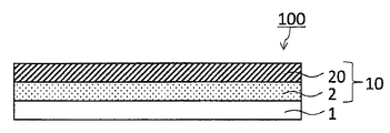
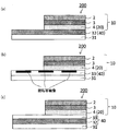
- a thermal transfer sheet 100 includes a substrate 1 and a transfer layer 10 that can be peeled from the substrate 1. And.
- the transfer layer 10 provided on the substrate 1 has a stacked structure in which two or more layers including the receiving layer 2 are stacked.
- the receiving layer 2 is a base layer among the layers constituting the transfer layer 10. Located closest to material 1. In the form shown in each drawing, the functional layer 20 is provided on the receiving layer 2.
- the thermal transfer sheet 100 of one embodiment has a receiving layer 2 for forming a thermal transfer image by transferring a transfer layer 10 including the receiving layer 2 onto an arbitrary transfer target (hereinafter referred to as a transfer target). It is a thermal transfer sheet used to obtain a thermal transfer image receiving sheet located on the outermost surface.
- a transfer target an arbitrary transfer target
- an intermediate transfer medium in which a receiving layer located on the outermost surface is provided so as to be transferable (detachable) from a substrate.
- a thermal transfer image can be formed on the receiving layer without transferring the receiving layer onto the transfer target.
- the intermediate transfer medium also serves as a thermal transfer image receiving sheet.
- the receiving layer on which the thermal transfer image is formed is provided on the transfer target by transferring the receiving layer on which the thermal transfer image is formed onto the transfer target. Get things.
- a release layer (sometimes referred to as a protective layer) and a receiving layer are provided in this order on a substrate, and the release layer is transferred onto the transfer target body together with the receiving layer.
- Possible intermediate transfer media are also known.
- the receiving layer 2 is not located on the outermost surface of the thermal transfer sheet 100 (in the form shown in each figure, the functional layer 20 is located on the outermost surface. A thermal transfer image cannot be formed on the outermost surface of the thermal transfer sheet 100 of one embodiment.
- the receiving layer 2 is located closest to the base material 1 among the layers constituting the transfer layer 10, and the transfer layer 10 is transferred onto the transfer target. The receiving layer 2 can be positioned on the outermost surface.
- the thermal transfer sheet 100 and the intermediate transfer medium of one embodiment are common, but a thermal transfer image can be formed before the receiving layer is transferred.
- the thermal transfer sheet of the embodiment is different from the intermediate transfer medium in that the layer located on the outermost surface is a receiving layer.
- a plurality of layers including the receiving layer and capable of being transferred from the base material may be collectively referred to as “transfer layer”.
- the “transfer layer” referred to in the thermal transfer sheet and the “transfer layer” referred to in the field of the intermediate transfer medium are clearly different in terms of whether or not the receiving layer is located on the outermost surface.
- each configuration of the thermal transfer sheet 100 of one embodiment will be specifically described.
- the base material 1 is an essential configuration in the thermal transfer sheet 100 according to an embodiment, and the transfer layer 10 provided on one surface of the base material 1 or an arbitrary one provided between the base material 1 and the transfer layer 10. It is provided in order to hold a layer (for example, an arbitrary release layer described later) and a back layer optionally provided on the other surface of the substrate 1.
- the material of the substrate 1 is not particularly limited, but it is desirable that the transfer layer 10 has mechanical characteristics that can withstand heat applied when transferring the transfer layer 10 onto a transfer target and that does not hinder handling.
- Such a substrate 1 examples include polyesters such as polyethylene terephthalate, polycarbonate, polyimide, polyetherimide, cellulose derivatives, polyethylene, polypropylene, polystyrene, acrylic, polyvinyl chloride, polyvinylidene chloride, nylon, polyether ether ketone, and the like.
- polyesters such as polyethylene terephthalate, polycarbonate, polyimide, polyetherimide, cellulose derivatives, polyethylene, polypropylene, polystyrene, acrylic, polyvinyl chloride, polyvinylidene chloride, nylon, polyether ether ketone, and the like.
- plastic films or sheets can be mentioned.
- the thickness of the base material 1 can be appropriately set according to the material so that the strength and heat resistance are appropriate, and the range of 2.5 ⁇ m to 100 ⁇ m is common.
- a transfer layer 10 is provided on the substrate 1.
- the transfer layer 10 is provided so as to be peelable from the substrate 1 and is a layer that moves onto the transfer target during thermal transfer.
- the transfer layer 10 has a laminated structure in which two or more layers are laminated, and includes at least the receiving layer 2.
- the transfer property of the transfer layer 10 when the transfer layer 10 is transferred onto the transfer target is that of the layer constituting the transfer layer 10 that is located closest to the substrate 1, that is, the layer located at the transfer interface. It is thought that it is influenced by transcription. Therefore, in order to improve the transferability of the transfer layer 10, it is necessary to configure the transfer layer 10 and sufficiently increase the transferability of the receiving layer 2, which is the layer located closest to the substrate 1. There is.
- the transferability referred to in this specification means that the transfer layer does not remain on the substrate side when the transfer layer is transferred to the transfer target side, or the transfer target and the thermal transfer sheet are integrated. It is an index indicating whether or not the transfer layer can be accurately transferred (transferred) to the transferred material side without being transferred, and high transferability means that energy is applied to the thermal transfer sheet, When the transfer layer is transferred to the transfer layer, the transfer layer corresponding to the region to which energy is applied does not remain on the substrate side, and the transfer target and the thermal transfer sheet are not integrated with each other. It means that it can be accurately migrated up.
- low transferability means that when energy is applied to the thermal transfer sheet and the transfer layer is transferred to the transfer target side, a part or all of the transfer layer corresponding to the area to which energy is applied
- the base material or a layer arbitrarily provided on the base material (for example, any release layer described later) and the transfer layer cause heat fusion, in other words, on the base material or the base material.
- the layer provided arbitrarily and the receiving layer included in the transfer layer cause thermal fusion, and the transfer layer cannot be peeled off from the base material, and the transferred object and the thermal transfer sheet are integrated, or
- the base material, or a layer arbitrarily provided on the base material, and the receiving layer included in the transfer layer cause heat fusion, and originally, the base material or any layer provided on the base material.
- the transfer layer to be peeled off at the interface peels off between the layers constituting the transfer layer. My, all of the receptor layer to be transferred onto the transfer receiving material, or part of means that remained to the substrate side.
- the transferability of the receiving layer has not been sufficiently studied at present, and when a conventionally known receiving layer is employed as the receiving layer 2 constituting the transfer layer 10, the transferability of the receiving layer itself is determined. Cannot be fully satisfied, and as a result, the transferability of the transfer layer is low. In particular, the transferability of the receiving layer tends to decrease as the energy applied to the thermal transfer sheet increases when the transfer layer is transferred.
- the thermal transfer sheet 100 is characterized in that the receiving layer 2 constituting the transfer layer 10 contains a cellulose resin. According to the receiving layer 2 having this feature, the transferability of the receiving layer 2 that is a layer located at the transfer interface can be sufficiently satisfied, and the energy applied to the thermal transfer sheet 100 is increased. However, the transferability of the transfer layer 10 including the receiving layer 2 can be satisfied. That is, in a wide energy range, transferability when transferring the transfer layer 10 including the receiving layer onto the transfer target can be improved.
- Examples of the cellulose resin contained in the receiving layer 2 include cellulose acetate resin, cellulose acetate butyrate resin, cellulose acetate propionate resin, nitrocellulose resin, and cellulose acetate.
- the receptor layer 2 in a preferred form contains one or both of cellulose acetate butyrate resin and cellulose acetate propionate resin. According to the receiving layer 2 containing cellulose acetate butyrate resin or cellulose acetate propionate resin, the transferability of the transfer layer 10 including the receiving layer 2 can be further improved.
- the receiving layer 2 may contain one kind of cellulose resin alone or may contain two or more kinds of cellulose resins. Moreover, other resin may be contained with the cellulose resin.
- the preferred form of the receiving layer 2 contains a cellulose resin having a number average molecular weight (Mn) of less than 70,000, preferably 55000 or less, particularly preferably 40000 or less.
- Mn number average molecular weight
- the transfer layer 10 including the receptive layer 2 in a preferred form as a cellulose resin, compared to a transfer layer including the receptive layer 2 containing only the cellulose resin having a number average molecular weight (Mn) of 70000 or more. It is possible to improve the foil cutting property when the transfer layer 10 is transferred onto the transfer body.
- the receiving layer 2 may contain two or more types of cellulosic resins having different number average molecular weights (Mn), and the preferable type of receiving layer 2 is at least one type of cellulosic resin of two or more types of cellulosic resins.
- the resin is a cellulose-based resin having the preferred number average molecular weight (Mn).
- Mn number average molecular weight
- the number average molecular weight (Mn) in the present specification means a molecular weight in terms of polystyrene measured by gel permeation chromatography (GPC) in accordance with JIS K7252-1: 2008.
- the content of the cellulosic resin there is no particular limitation on the content of the cellulosic resin, and with a very small amount of addition, for example, even when the content of the cellulosic resin relative to the total solid content of the receiving layer 2 is about 0.5% by mass,
- the transfer property of the transfer layer including the receiving layer 2 can be improved.
- the receiving layer 2 containing the cellulose resin includes the receiving layer 2 in a wider energy range as compared to the receiving layer not containing the cellulose resin.
- the transferability of the transfer layer can be made extremely good. This is also clear from the results of Examples and Comparative Examples.
- the receptor layer 2 in a preferred form contains a cellulose resin in a range of less than 25% by mass with respect to the total solid content of the receptor layer 2, and more preferably in a range of 1% by mass or more and less than 22% by mass. Contains. There is no limitation in particular also about the upper limit of content of a cellulose resin, and it is 100 mass%.
- the content of the cellulosic resin is not limited in any way, but the content of the cellulosic resin is a dye used for forming a thermal transfer image on the receiving layer 2 by transferring the dye of the dye layer. It is desirable to determine in consideration of releasability with a layer (hereinafter sometimes referred to as dye releasability). In addition, on the dye layer side, when measures are taken to improve dye releasability, for example, when the dye layer contains a release agent, the content of the cellulose resin What is necessary is just to set it as arbitrary contents, without considering.
- the content of the cellulose resin when no measure against dye releasability is taken on the dye layer side, it is preferable to determine the content of the cellulose resin according to the type of resin contained in the dye layer.
- the dye releasability varies depending on the type of resin contained in the dye layer, for example, the resin contained in the dye layer is a polyvinyl acetal resin or a polyvinyl butyral resin,
- the resin contained in the dye layer is a polyvinyl acetal resin or a polyvinyl butyral resin
- content of the cellulose resin with respect to the solid content total mass of the receiving layer 2 shall be less than 25 mass%.
- the receiving layer 2 and the dye layer do not contain a release agent or the like, use a dye layer containing a resin having good dye releasability with a receiving layer containing a cellulose resin. Therefore, the dye releasability can be improved regardless of the content of the cellulose resin. That is, the content of the cellulose resin with respect to the total solid mass of the receiving layer can be 100% by mass. Further, it is possible to improve the dye releasability by incorporating a release agent into the receiving layer 2.
- the receiving layer 2 may contain a resin other than the cellulose resin, a release agent, and the like.
- resins other than cellulose resins include polyolefin resins such as polypropylene, halogenated resins such as polyvinyl chloride or polyvinylidene chloride, polyvinyl acetate, vinyl chloride-vinyl acetate copolymers, ethylene-acetic acid.
- vinyl resins such as vinyl copolymers or polyacrylic acid esters, polyester resins, polystyrene resins, acrylic resins, and the like.
- release agent examples include solid waxes such as polyethylene wax, amide wax, and Teflon (registered trademark) powder, fluorine or phosphate surfactant, silicone oil, reactive silicone oil, and curable silicone oil. And various modified silicone oils, and various silicone resins.
- the receiving layer 2 is a coating solution for a receiving layer in which a resin other than the above cellulose-based resin, a cellulose-based resin added as necessary, and additives such as a release agent are dispersed or dissolved in an appropriate solvent. This is coated and dried on the substrate 1 or an arbitrary layer provided on the substrate 1 by means of a gravure printing method, a screen printing method or a reverse coating method using a gravure plate. Can be formed. There is no limitation in particular about the thickness of the receiving layer 2, Usually, it is the range of 0.3 to 10 micrometer.
- a functional layer 20 is provided on the receiving layer 2.
- the functional layer 20 is an essential configuration in the thermal transfer sheet 100 of one embodiment.
- the functional layer 20 can be appropriately selected according to functions required for the transfer layer 10, for example, functions such as concealment and adhesiveness, and the specific functions are not limited. That is, the layer provided on the receiving layer 2 is not limited in any way, and may be any layer as long as it is a layer different from the receiving layer 2.
- the thermal transfer sheet 100 of one embodiment is provided with the functional layer 20 on the receiving layer 2, and the functional layer 20 is positioned on the outermost surface of the thermal transfer sheet 100 of one embodiment. To do.
- the functional layer 20 may have a single layer configuration or a stacked configuration. Hereinafter, the functional layer 20 will be described with an example.
- the transferability of the transfer layer is influenced by the number of layers constituting the transfer layer, and usually has a transfer layer having a laminated structure in which two or more layers are laminated and a single layer structure having one layer.
- the transferability of the transfer layer is compared, the transferability tends to be lower in a transfer layer having a laminated structure in which the number of layers constituting the transfer layer is large.
- the thermal transfer sheet 100 according to an embodiment has a laminated structure in which the transfer layer 10 is formed by laminating two or more layers. However, as described above, the thermal transfer sheet 100 is a layer constituting the transfer layer 10.
- the receiving layer 2 located closest to the base material 1 contains a cellulose resin, and the transferability at the transfer interface is improved. Therefore, according to the transfer layer 10 including the receiving layer 2 containing the cellulose resin, various functional layers 20 are laminated on the receiving layer 2 to increase the number of layers constituting the transfer layer 10. Even when the thickness of the transfer layer 10 is increased, the transferability of the transfer layer 10 can be sufficiently satisfied.
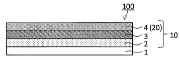
- the functional layer 20 as an example has a function of concealing a part of the surface of the transfer target body onto which the transfer layer 10 has been transferred.
- the functional layer 20 having a function of concealing a part of the surface of the transfer target body onto which the transfer layer 10 has been transferred is referred to as a concealment layer 4.
- the hiding layer 4 as an example is composed of a binder resin and a colorant.
- the binder resin include polyester resin, urethane resin, epoxy resin, phenol resin, acrylic resin, and vinyl chloride-vinyl acetate copolymer resin.
- the colorant examples include known colorants such as titanium oxide, zinc oxide, carbon black, iron oxide, iron yellow, ultramarine blue, hologram powder, aluminum powder, metallic pigment, and pearl pigment.
- the concealing layer 4 may contain one kind of these binder resins or may contain two or more kinds. The same applies to the colorant.
- the method for forming the masking layer 4 is not particularly limited, and a coating solution for the masking layer is prepared by dispersing or dissolving the binder resin, colorant, and additives added as necessary in an appropriate solvent.
- This can be formed on the receiving layer 2 by coating and drying by a conventionally known forming means such as a gravure coating method, a roll coating method, a screen printing method, a reverse roll coating method using a gravure plate, or the like. it can.
- the thickness of the masking layer 4 is not particularly limited, but may be appropriately set in consideration of the masking property of the masking layer 4. Note that when the thickness of the masking layer 4 is less than 0.1 ⁇ m, the masking property tends to decrease. In consideration of this point, the thickness of the masking layer 4 is preferably 0.1 ⁇ m or more. Although there is no limitation in particular about the preferable upper limit of the thickness of a concealing layer, it is about 5 micrometers.
- the foil breakability of the transfer layer 10 is improved between the receiving layer 2 and the concealing layer 4 (functional layer 20), specifically, when the transfer layer 10 is transferred.
- An intermediate layer 3 can also be provided in order to prevent the occurrence of pulling and character collapse, or to improve the adhesion between the receiving layer 2 and the concealing layer 4.
- the tailing referred to in the specification of the present application is such that when the transfer layer is transferred onto the transfer target, the boundary between the transfer region and the non-transfer region of the transfer layer is the starting point and protrudes from the boundary to the non-transfer region side This means the phenomenon that the transfer layer is transferred to the surface.
- character collapse referred to in the present specification means that a transfer target region surrounded or sandwiched between transfer regions represented as characters is transferred by a phenomenon similar to tailing, and the original character is reproduced. It means a phenomenon that has not been done.
- the intermediate layer 3 as an example is, for example, a urethane resin, a polyester resin, an acrylic resin, a vinyl chloride-vinyl acetate copolymer resin, a binder resin such as a polyvinyl pyrrolidone resin, a polyvinyl alcohol resin, and, if necessary, alumina, It contains inorganic particles such as silica, titanium oxide and carbon black. According to the intermediate layer containing inorganic particles together with the binder resin, the foil breakability of the transfer layer 10 including the intermediate layer 3 can be further improved.
- the intermediate layer 3 in a preferable form contains alumina fine particles and silica fine particles together with the binder resin.
- the intermediate layer in a particularly preferred form contains alumina fine particles derived from alumina sol and silica fine particles derived from colloidal silica together with a binder resin.
- middle layer can also be formed from inorganic fine particles, without using binder resin.
- aqueous resin refers to a water-soluble resin or a resin that is insoluble in an aqueous solvent but can be dispersed in an aqueous solvent, such as an emulsion or a dispersion.
- aqueous solvent include water and a mixed solvent of water and alcohol.
- water-soluble resin examples include polyvinyl pyrrolidone resin, polyvinyl alcohol resin, polyacrylic acid, polyhydroxyethyl acrylate, water-soluble (or water-dispersed) polyester resin, water-soluble (or water-dispersed) polyurethane resin, and water-dispersible vinyl chloride.
- examples thereof include resins, water-dispersible acrylic chloride resins, water-dispersible epoxy resins, gelatin, hydroxyethyl cellulose resins, hydroxypropyl cellulose resins, and carboxymethyl cellulose.
- the method for forming the intermediate layer 3 is not particularly limited, and an intermediate layer coating solution is prepared by dissolving or dispersing a binder resin and, if necessary, an additive, in an appropriate solvent, and this is applied to the receiving layer 2. Further, it can be formed by coating and drying by a conventionally known forming means such as a gravure coating method, a roll coating method, a screen printing method, or a reverse roll coating method using a gravure plate.
- the thickness of the intermediate layer is not particularly limited, but is preferably 0.01 ⁇ m or more and 5 ⁇ m or less, and particularly preferably 0.02 ⁇ m or more and 3 ⁇ m or less.
- the functional layer 20 as another example has a function of improving the adhesion between the transfer target and the transfer layer 10.
- the functional layer 20 having adhesiveness is referred to as an adhesive layer.
- the adhesive layer any conventionally known one in the field of thermal transfer sheets can be appropriately selected and used.
- the adhesive layer contains an ultraviolet absorber copolymer resin, an acrylic resin, a vinyl chloride-vinyl acetate copolymer resin, an epoxy resin, a polyester resin, a polycarbonate resin, a butyral resin, a polyamide resin, a vinyl chloride resin, and the like. ing.
- the formation method of the adhesive layer is not particularly limited.
- An adhesive layer coating solution in which an activator, a release agent, etc. are dispersed or dissolved in an appropriate solvent is prepared, and this is applied to the receiving layer 2 by a method such as gravure coating or gravure reverse coating and dried. Can be formed.
- the thickness of an contact bonding layer the range of 0.5 micrometer or more and 10 micrometers or less is preferable, and the range of 0.8 micrometer or more and 2.0 micrometers or less is more preferable.
- a release layer (not shown) can be provided between the substrate 1 and the transfer layer 10.
- the release layer is an arbitrary configuration in the thermal transfer sheet 100 of one embodiment, and is a layer that does not constitute the transfer layer 10. That is, it is a layer remaining on the substrate 1 side when the transfer layer 10 is transferred onto the transfer target.
- the transferability of the transfer layer 10 can be further improved in combination with the good transferability of the receiving layer 2 containing the cellulose resin. it can.
- the binder resin contained in the release layer examples include waxes, silicone wax, silicone resin, silicone-modified resin, fluorine resin, fluorine-modified resin, polyvinyl alcohol, acrylic resin, heat-crosslinkable epoxy-amino resin, and heat-crosslinking. Alkyd-amino resin and the like.
- the release layer may be composed of one kind of resin or may be composed of two or more kinds of resins.
- the release layer may be formed by using a cross-linking agent such as an isocyanate compound, a catalyst such as a tin-based catalyst, and an aluminum-based catalyst in addition to the releasable resin.
- the thickness of the release layer is generally in the range of 0.2 ⁇ m to 5 ⁇ m.
- the release layer is formed by dissolving or dispersing the resin in a suitable solvent to prepare a release layer coating solution, which is then applied to the substrate 1 by a gravure printing method, a screen printing method or a gravure plate. It can be formed by coating and drying by a conventionally known means such as a reverse coating method using a bismuth.
- a back layer (not shown) can be provided on the surface of the substrate 1 opposite to the surface on which the transfer layer 10 is provided.
- a back surface layer is arbitrary structures in the thermal transfer sheet 100 of one Embodiment.
- the material of the back layer for example, cellulose resins such as cellulose acetate butyrate and cellulose acetate propionate, vinyl resins such as polyvinyl butyral and polyvinyl acetal, polymethyl methacrylate, polyethyl acrylate, polyacrylamide
- An acrylic resin such as acrylonitrile-styrene copolymer, a polyamide resin, a polyamideimide resin, a polyester resin, a polyurethane resin, a natural or synthetic resin such as silicone-modified or fluorine-modified urethane, or a mixture thereof.
- the back layer may contain a solid or liquid lubricant.
- the lubricant include various waxes such as polyethylene wax and paraffin wax, higher aliphatic alcohols, organopolysiloxanes, anionic surfactants, cationic surfactants, amphoteric surfactants, nonionic surfactants, fluorine And surfactants, organic carboxylic acids and derivatives thereof, metal soaps, fluorine resins, silicone resins, fine particles of inorganic compounds such as talc and silica.
- the mass of the lubricant with respect to the total mass of the back layer is in the range of 5 to 50% by mass, preferably in the range of 10 to 40% by mass.
- the method for forming the back layer there is no particular limitation on the method for forming the back layer, and a resin, a lubricant added as necessary, and the like are dissolved or dispersed in an appropriate solvent to prepare a back layer coating solution. It can form by apply
- the thickness of the back layer is preferably in the range of 1 ⁇ m to 10 ⁇ m.
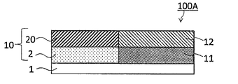
- a transfer layer 10 and a dye layer 12 are provided in the surface order on the same surface of the substrate 1.
- a dye primer layer 11 is provided between the substrate 1 and the dye layer 12. That is, in the thermal transfer sheet 100A of another embodiment, in the thermal transfer sheet 100 of one embodiment described above, the dye layer 12 is further provided on the same surface as the surface on which the transfer layer 10 of the substrate 1 is provided. The provided configuration is taken.
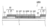
- a transfer layer 10, a dye layer 12, and an optional protective layer 13 are repeatedly provided in the surface order on the same surface of the substrate 1.
- an arbitrary color material layer (not shown) containing a pigment in place of or along with an arbitrary protective layer 13 or an arbitrary color panel (not shown) composed of a hologram layer. ) Etc. can also be provided in the surface sequential order.
- the order in which these arbitrary layers are repeatedly provided in the surface order is not limited to the illustrated form.
- both the formation of the thermal transfer image receiving sheet 200 as shown in FIG. 5 and the formation of the thermal transfer image on the receiving layer 2 of the formed thermal transfer image receiving sheet are performed. be able to.
- the thermal transfer sheet 100A of another embodiment and transferring the transfer layer 10 onto the transfer target the functional layer 20 and the receiving layer 2 are laminated in this order on the transfer target.
- a thermal transfer image-receiving sheet can be obtained.
- a thermal transfer image can be formed.
- thermal transfer sheet 100A each configuration of the thermal transfer sheet 100A according to another embodiment will be described focusing on differences from the thermal transfer sheet 100 according to one embodiment. Unless otherwise specified, the one described in the thermal transfer sheet 100 of the above embodiment can be used as it is.
- the dye layer 12 contains a sublimable dye and a binder resin.
- the dye layer 12 may be formed with only one color layer selected as appropriate when the desired image is monochromatic, or as shown in FIG. 4 when the desired image is a full color image.
- a plurality of dye layers containing sublimable dyes having different hues, such as yellow dye 12Y, magenta dye 12M, and cyan dye 12C, may be repeatedly formed on the same surface of the same base material in the surface order. 4, the transfer layer 10, the yellow dye 12Y, the magenta dye 12M, the cyan dye 12C, and the protective layer 13 are repeatedly formed in this order on the same surface of the base material 1. It does not have to be. Also, this order is not necessary.
- the dye layer 12 is not limited to what is demonstrated below, A conventionally well-known dye layer can be applied as it is in the field
- the sublimable dye is not particularly limited, but a dye having a sufficient color density and not discolored by light, heat, temperature or the like is preferable.
- Examples of such sublimable dyes include diarylmethane dyes, triarylmethane dyes, thiazole dyes, merocyanine dyes, pyrazolone dyes, methine dyes, indoaniline dyes, pyrazolomethine dyes, acetophenone azomethine, pyrazolo dyes.
- Azomethine dyes such as azomethine, imidazolazomethine, imidazoazomethine and pyridone azomethine, xanthene dyes, oxazine dyes, cyanostyrene dyes such as dicyanostyrene and tricyanostyrene, thiazine dyes, azine dyes, acridine dyes, Benzeneazo dyes, pyridone azo, thiophenazo, isothiazole azo, pyrrole azo, pyrazole azo, imidazole azo, thiadiazole azo, triazole azo, disazo azo dyes, spiropyran Fee, India Linos Piropi run dyes, fluoran dye, rhodamine lactam-based dyes, naphthoquinone dyes, anthraquinone dyes, quinophthalone dyes, and the like.
- red dyes such as MSRedG (manufactured by Mitsui Toatsu Chemical Co., Ltd.), Macrolex Red Violet R (manufactured by Bayer), CeresRed 7B (manufactured by Bayer), Samalon Red F3BS (manufactured by Mitsubishi Chemical), and holon brilliant yellow Yellow dyes such as 6GL (manufactured by Clariant), PTY-52 (manufactured by Mitsubishi Kasei), Macrolex Yellow 6G (manufactured by Bayer), Kayaset Blue 714 (manufactured by Nippon Kayaku Co., Ltd.), Waxoline Blue AP-FW ( ICI), Holon Brilliant Blue SR (Sand), MS Blue 100 (Mitsui Toatsu Chemical), C.I. I. And blue dyes such as Solvent Blue 63.
- MSRedG manufactured by Mitsui Toatsu Chemical Co., Ltd.
- Macrolex Red Violet R manufactured by Bayer
- CeresRed 7B manufactured
- the content of the sublimable dye is preferably in the range of 50% by mass to 350% by mass, and more preferably in the range of 80% by mass to 300% by mass, based on the total solid content of the binder resin described later. preferable.
- the content of the sublimable dye is less than the above range, the printing density tends to decrease, and when it exceeds the above range, the storage stability and the like tend to decrease.
- Binder resin The binder resin contained in the dye layer and supporting the sublimable dye is not particularly limited, and those having a certain degree of heat resistance and having a moderate affinity with the sublimable dye can be used.
- binder resins include cellulose resins such as nitrocellulose, cellulose acetate butyrate, and cellulose acetate propionate; vinyl resins such as polyvinyl acetate, polyvinyl butyral, and polyvinyl acetal; poly (meth) acrylate, An acrylic resin such as poly (meth) acrylamide; a polyurethane resin; a polyamide resin; a polyester resin;
- the binder resin is preferably contained in an amount of 20% by mass or more based on the total solid content of the dye layer 12.
- the binder resin is preferably contained in an amount of 20% by mass or more based on the total solid content of the dye layer 12.
- the dye layer 12 may contain additives such as inorganic particles and organic fine particles.
- inorganic particles include talc, carbon black, aluminum, molybdenum disulfide, and examples of organic fine particles include polyethylene wax and silicone resin fine particles.
- the dye layer 12 may contain a release agent.
- examples of the mold release agent include modified or unmodified silicone oil (including those referred to as silicone resins), phosphate esters, and fatty acid esters.
- the method for forming the dye layer 12 is not particularly limited, and a binder resin, a sublimation dye, an additive added as necessary, and a release agent are dissolved or dispersed in an appropriate solvent, and the dye layer coating is performed.
- a working solution is prepared, and this dye layer coating solution is formed by coating and drying on the dye primer layer 11 to be described later by a conventionally known coating means such as a gravure coater, a roll coater, or a wire bar. Can do.
- the thickness of the dye layer is generally in the range of 0.2 ⁇ m to 2.0 ⁇ m.
- a dye primer layer 11 may be provided between the base material 1 and the dye layer 12 for the purpose of improving the adhesion between the base material 1 and the dye layer 12.
- the dye primer layer 11 is not particularly limited, and a conventionally known dye primer layer can be appropriately selected and used in the field of thermal transfer sheets.
- the dye primer layer 11 as an example is made of a resin material.
- the resin material constituting the dye primer layer 11 include polyester resins, polyvinyl pyrrolidone resins, polyvinyl alcohol resins, polyacrylate resins, polyvinyl acetate resins, polyurethane resins, styrene acrylate resins, polyacrylamides. Resin, polyamide resin, polyvinyl acetoacetal, polyvinyl butyral, and the like.
- the dye primer layer 11 may contain various additives such as organic particles and inorganic particles together with these resin components.
- the method for forming the dye primer layer 11 is not particularly limited, and a dye primer layer coating solution is prepared by dissolving or dispersing the resin components exemplified above and additives added as necessary in an appropriate solvent.
- This can be formed on the substrate 1 by coating and drying by a conventionally known forming means such as a gravure coating method, a roll coating method, a screen printing method, a reverse roll coating method using a gravure plate, etc. it can.
- a conventionally known forming means such as a gravure coating method, a roll coating method, a screen printing method, a reverse roll coating method using a gravure plate, etc. it can.
- the thickness of the dye primer layer 11 Usually, it is the range of 0.02 micrometer or more and 1 micrometer or less.
- thermal transfer image-receiving sheet (hereinafter, referred to as a thermal transfer image receiving sheet according to an embodiment) formed using the thermal transfer sheet 100 according to the embodiment will be described with an example.
- the transfer layer 10 is provided on the transfer target so that the receiving layer 2 is located on the outermost surface.
- the transferred object in the form shown in the figure has a configuration in which a pattern layer 40 is provided on a substrate 31.
- the pattern layer 40 is the arbitrary structures in the thermal transfer image receiving sheet 200 of one Embodiment.
- FIG. 5 is a schematic cross-sectional view of a thermal transfer image receiving sheet according to an embodiment.
- the transfer layer 10 is provided on the transferred body so that a part of the surface of the transferred body is exposed.
- the transfer layer 10 can be provided on the transfer target without exposing the surface of the transfer target.
- the receiving layer 2 constituting the transfer layer 10 is referred to as a first receiving layer 2.
- Base material for thermal transfer image-receiving sheet There is no particular limitation on the base material 31 (hereinafter referred to as the base material 31) of the thermal transfer image-receiving sheet 200, and a conventionally known material can be appropriately selected and used as the base material of the thermal transfer image-receiving sheet.
- Base materials 31 generally used in the field of thermal transfer image-receiving sheets include high-quality paper, art paper, lightweight coated paper, fine coated paper, coated paper, cast coated paper, synthetic resin or emulsion impregnated paper, synthetic rubber latex impregnated Examples of the paper base material include paper and synthetic resin-containing paper.
- the substrate 1 described in the thermal transfer sheet 100 of the above-described embodiment can be used as it is.
- a pattern layer 40 is provided on the substrate 31.
- the pattern layer 40 may be a layer in which some pattern is formed or a colored layer, and the pattern of the pattern layer 40 is not limited in any way.
- a conventionally known hologram layer 32 may be used as the pattern layer 40, and the second receiving layer 33 on which a thermal transfer image is formed as shown in FIG.
- the pattern layer 40 may be used.
- the pattern layer 40 may be a laminate of the hologram layer 32 and the second receiving layer 33 from the base material 31 side.
- the second receiving layer 33 in FIG. 6C is a receiving layer before the thermal transfer image is formed, but may be a receiving layer on which the thermal transfer image is formed in advance.
- the second receiving layer 33 is not limited in any way, and a conventionally known layer can be appropriately selected and used as the receiving layer of the thermal transfer image receiving sheet.
- the receiving layer 2 described for the thermal transfer sheet 100 of the above-described embodiment can be used as it is.
- the hologram layer 32 for example, a layer provided with a concavo-convex pattern (interference fringes) or a sheet on which a commercially available hologram is formed may be used. Colored ones can also be used.
- FIGS. 6A to 6C are schematic cross-sectional views of the thermal transfer image receiving sheet of one embodiment.
- the transfer layer 10 described with reference to the thermal transfer sheet 100 of the above-described embodiment can be appropriately selected and used, and detailed description thereof is omitted here.
- the transfer layer 10 can be transferred such that a part of the surface of the pattern layer 40 is exposed.
- a method for forming a printed material according to an embodiment includes a step of preparing a transfer target body and a thermal transfer sheet according to another embodiment described above, and a transfer target prepared in the preparation step.
- the method includes a step of transferring a transfer layer of the thermal transfer sheet thus formed, and a step of forming a thermal transfer image on the transfer layer transferred onto the transfer target.
- thermal transfer sheet As the thermal transfer sheet prepared in this step, the thermal transfer sheet of the other embodiment described above can be used as it is, and detailed description thereof is omitted here.
- the transfer target examples include the base material 31 described in the thermal transfer image receiving sheet 200 of the above-described embodiment, or the transfer target provided with the pattern layer 40 on the base material 31.
- the substrate 31 and the pattern layer 40 described in the thermal transfer image-receiving sheet 200 of the above-described embodiment may be appropriately selected to form a transfer body provided with a pattern layer on the substrate.
- the pattern layer 40 also includes a pattern layer 40 that becomes a pattern by finally forming a thermal transfer image.
- the pattern layer 40 may be a receiving layer before the thermal transfer image is formed.
- This step is a step of transferring the transfer layer of the thermal transfer sheet prepared in the same preparation step onto the transfer target prepared in the preparation step. By passing through this step, a thermal transfer image receiving sheet is obtained in which the transfer layer is transferred onto the transfer target. That is, the thermal transfer image receiving sheet of the one embodiment is obtained.
- the transfer layer 10 may be transferred so that a part of the surface of the pattern layer is exposed.
- the transfer layer is transferred onto the transfer target with good transferability in the step of transferring the transfer layer. can do.
- This step is a step of forming a thermal transfer image by diffusing and transferring a sublimable dye on the receiving layer of the thermal transfer image receiving sheet obtained in the above transfer step.
- a concealing layer, an intermediate layer, and a receiving layer are provided in this order so that a part of the pattern layer is exposed on the transfer object having the pattern layer.
- a printed matter having a thermal transfer image formed thereon is obtained.
- the thermal transfer sheet prepared in the above-described preparation step is the thermal transfer sheet.
- the sheet can be used as it is.
- the thermal transfer sheet prepared in the preparing step is the thermal transfer sheet 100 according to the embodiment described above that does not include the dye layer 12, a conventionally known one that includes a dye layer containing a sublimable dye. A thermal transfer sheet may be used.
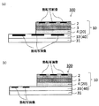
- FIG. 7 is a schematic cross-sectional view showing an example of a printed material 300 formed by the method for forming a printed material according to an embodiment.
- the pattern layer 40 of the transfer target prepared in the preparation step is the second receiving layer 33 on which a thermal transfer image is formed in advance, a thermal transfer image is formed on the receiving layer 2 in the step of forming the thermal transfer image.
- a part of the picture layer 40 is concealed by the concealing layer 4, and a printed product 300 in which a thermal transfer image is formed on the concealing layer is obtained.
- the pattern layer 40 of the transfer target prepared in the preparation step is the second receiving layer 33 before the thermal transfer image is formed, the surface is exposed in the step of forming the thermal transfer image.
- a thermal transfer image is formed on the second receiving layer 33 of the transfer target, and a thermal transfer image is formed on the receiving layer 2 to obtain a printed product 300 having the form shown in FIG. 7B.
- the pattern layer 40 is not limited to the illustrated form, and various forms of the pattern layer 40 described in the thermal transfer image receiving sheet 200 of one embodiment can be appropriately selected and used.
- the transfer is performed on the transfer target. Transferability when transferring the layer 10 can be improved. Specifically, it is possible to improve the transferability when transferring the transfer layer onto the transfer target in a wide energy range. Further, by using the thermal transfer sheet of another embodiment, it is possible to form a thermal transfer image with one thermal transfer sheet.
- a printed matter 300 (hereinafter, referred to as a printed matter according to an embodiment) formed using the thermal transfer sheet 100 according to the embodiment will be described.
- a printed product 300 according to an embodiment has a thermal transfer image formed on the first receiving layer 2 of the thermal transfer image receiving sheet 200 according to the embodiment described above. It is characterized by being.
- part and % are based on mass. Moreover, about the component which has solid content ratio, the value of the mass converted into solid content is shown.
- Example 1 A polyethylene terephthalate film having a thickness of 5 ⁇ m was used as a base material, and a back layer coating solution having the following composition was applied thereon so as to be 1.0 g / m 2 when dried to form a back layer.
- a first receiving layer coating liquid 1 having the following composition is applied to the surface of the substrate opposite to the side on which the back layer is provided so as to be 1.0 g / m 2 when dried. Formed.
- a first intermediate layer coating solution having the following composition is applied on the first receiving layer so as to be 0.15 g / m 2 upon drying to form a first intermediate layer.
- the coating solution for the concealing layer having the following composition is applied at a dryness of 2.0 g / m 2 to form a concealing layer, and the first receiving layer, the first intermediate layer, A thermal transfer sheet of Example 1 was obtained in which a transfer layer in which concealing layers were laminated in this order was provided, and a back layer was provided on the other surface of the substrate.
- Example 2 In place of the first receiving layer coating solution 1, 1.0 part of cellulose acetate butyrate resin (CAB381-0.5 Eastman Chemical Co., Ltd.) (Mn: 30000) in the first receiving layer coating solution 1 was changed to 1.0 part of cellulose acetate butyrate resin (Mn: 20000) (CAB381-0.1 Eastman Chemical Co., Ltd.). Except for the formation, a thermal transfer sheet of Example 2 was obtained in the same manner as Example 1.
- Example 3 In place of the first receiving layer coating solution 1, 1.0 part of cellulose acetate butyrate resin (CAB381-0.5 Eastman Chemical Co., Ltd.) (Mn: 30000) in the first receiving layer coating solution 1 A first receptive layer was formed using a coating solution 3 for the first receptive layer, which was changed to 1.0 part of cellulose acetate butyrate resin (Mn: 40000) (CAB381-2 Eastman Chemical Co., Ltd.). A thermal transfer sheet of Example 3 was obtained in the same manner as Example 1 except for the above.
- Example 4 In place of the first receiving layer coating solution 1, 1.0 part of cellulose acetate butyrate resin (CAB381-0.5 Eastman Chemical Co., Ltd.) (Mn: 30000) in the first receiving layer coating solution 1 was changed to 1.0 part of cellulose acetate butyrate resin (Mn: 30000) (CAB551-0.2 Eastman Chemical Co., Ltd.) using the first receiving layer coating solution 4 to form the first receiving layer.
- a thermal transfer sheet of Example 4 was obtained in the same manner as Example 1 except that it was formed.
- Example 5 In place of the first receiving layer coating solution 1, 1.0 part of cellulose acetate butyrate resin (CAB381-0.5 Eastman Chemical Co., Ltd.) (Mn: 30000) in the first receiving layer coating solution 1 was changed to 1.0 part of cellulose acetate butyrate resin (Mn: 12000) (CAB321-0.1 Eastman Chemical Co., Ltd.) using the first receiving layer coating solution 5. Except for the formation, a thermal transfer sheet of Example 5 was obtained in the same manner as Example 1.
- Example 6 In place of the first receiving layer coating solution 1, 1.0 part of cellulose acetate butyrate resin (CAB381-0.5 Eastman Chemical Co., Ltd.) (Mn: 30000) in the first receiving layer coating solution 1
- the first receptive layer was prepared using a first receptive layer coating solution 6 that was changed to 1.0 part of cellulose acetate propionate resin (Mn: 25000) (CAP482-0.5 Eastman Chemical Co., Ltd.).
- a thermal transfer sheet of Example 6 was obtained in the same manner as in Example 1 except that was formed.
- Example 7 A thermal transfer sheet of Example 7 was obtained in the same manner as in Example 1 except that the first receiving layer coating solution 1 was changed to the first receiving layer coating solution 7 having the following composition.
- Example 8 A thermal transfer sheet of Example 8 was obtained in the same manner as in Example 1 except that the first receiving layer coating liquid 1 was changed to the first receiving layer coating liquid 8 having the following composition.
- Example 9 A thermal transfer sheet of Example 9 was obtained in the same manner as in Example 1 except that the first receiving layer coating solution 1 was changed to the first receiving layer coating solution 9 having the following composition.
- Example 10 In place of the first receiving layer coating solution 1, 1.0 part of cellulose acetate butyrate resin (CAB381-0.5 Eastman Chemical Co., Ltd.) (Mn: 30000) in the first receiving layer coating solution 1 A first receptive layer was formed using a coating solution 10 for the first receptive layer, which was changed to 1.0 part of cellulose acetate butyrate resin (Mn: 70000) (CAB381-20 Eastman Chemical Co., Ltd.). Except for this, the thermal transfer sheet of Example 10 was obtained in the same manner as Example 1.
- Example 11 A thermal transfer sheet of Example 11 was obtained in the same manner as Example 1 except that the first intermediate layer was not formed between the hiding layer and the first receiving layer.
- Comparative Example 1 A thermal transfer sheet of Comparative Example 1 was obtained in the same manner as in Example 1 except that the first receiving layer coating solution 1 was changed to the first receiving layer coating solution A having the following composition.
- ⁇ Coating liquid A for first receiving layer > ⁇ 16.8 parts of vinyl chloride-vinyl acetate copolymer resin (Solvine CNL Nissin Chemical Industry Co., Ltd.) ⁇ Silicone oil 1.2 parts (X-22-3000T Shin-Etsu Chemical Co., Ltd.) ⁇ Silicone oil 1.2 parts (X-24-510 Shin-Etsu Chemical Co., Ltd.) ⁇ Silicon oil 0.8 parts (KF-352A Shin-Etsu Chemical Co., Ltd.) ⁇ Methyl ethyl ketone 40 parts ⁇ Toluene 40 parts
- ⁇ Creation of transferred object> A polyethylene terephthalate film having a thickness of 25 ⁇ m was used as a substrate, and a coating liquid for hologram layer having the following composition was applied thereon by a gravure coating method so that the coating amount at the time of drying was 2 g / m 2. Then, the coated layer was embossed using a metal plate with hologram interference fringes formed in a concavo-convex shape to give hologram concavo-convexities to form a hologram layer.
- a reflective layer is formed by vapor-depositing aluminum to a thickness of 30 nm on the surface of the hologram layer where the irregularities are provided, and a hologram sheet is obtained in which the base material, the hologram layer, and the reflective layer are laminated in this order. It was.
- RC paper STF-150, manufactured by Mitsubishi Paper Industries Co., Ltd., 190 ⁇ m
- an adhesive layer coating solution having the following composition was applied onto the support by a gravure coating method during drying.
- the adhesive layer is formed so that the amount is 3.0 g / m 2, and the hologram sheet obtained above is laminated with the adhesive layer so that the reflection layer of the hologram sheet and the support are opposed to each other.
- a support / adhesive layer / reflection layer / hologram layer / base material) was obtained.
- a coating solution for the second intermediate layer having the following composition is dried by gravure coating.
- a second intermediate layer is formed by coating so that the coating amount is 1.2 g / m 2, and a second receiving layer coating solution having the following composition is formed on the second intermediate layer by a gravure coating method.
- the support / adhesive layer / reflective layer / hologram layer / base material / second intermediate layer / The transferred object in which the second receiving layer was laminated in this order was obtained.
- ⁇ Second intermediate layer coating solution> Water-dispersed polyester resin (solid content 25%, Tg 20 ° C) 10 parts (Vylonal MD-1480 Toyobo Co., Ltd.) -Conductive synthetic layered silicate (average primary particle size 25 nm) 10 parts (Laponite JS Wilber Ellis) ⁇ Water 80 parts
- Printing Thermal head KEE-57-12GAN2-STA (manufactured by Kyocera Corporation) Heating element average resistance: 3303 ( ⁇ ) Main scanning direction printing density: 300 dpi Sub-scanning direction printing density: 300 dpi Printing voltage: 18 (V) 1 line cycle: 1.5 (msec.) Printing start temperature: 35 (°C) Pulse duty ratio: 85%
- thermo transfer sheet (i) A polyethylene terephthalate film having a thickness of 5 ⁇ m was used as a base material, and a back layer coating solution having the above composition was applied at a dryness of 1.0 g / m 2 to form a back layer.
- a dye primer layer was formed on the other surface of the base material by applying a coating solution for a dye primer layer having the following composition to 0.15 g / m 2 when dried.
- the yellow and magenta dye layer coating liquid having the above composition is applied in the surface order so as to be 0.7 g / m 2 when dried to form a yellow dye layer and a magenta dye layer.
- Thermal transfer sheet (i) was obtained.
- ⁇ Dye primer layer coating solution > -Colloidal alumina (solid content 10.5%) 3.5 parts (alumina sol 200 Nissan Chemical Industries, Ltd.) ⁇ Vinyl acetate vinylpyrrolidone copolymer 1.5 parts (PVP / VA E-335 ISP Japan Co., Ltd.) ⁇ 95 parts of water / isopropyl alcohol mixed solvent (1: 1)
- Peeling device Surface property measuring machine HEIDON-14 Shinto Kagaku Co., Ltd. Peeling speed: 200 mm / min Sample width to measure: 70 mm Peel angle: 180 °
- SYMBOLS 100, 100A Thermal transfer sheet 1 ... Base material 2 ... Receiving layer, 1st receiving layer 3 ... Intermediate layer 4 ... Concealing layer 10 ... Transfer layer 11 . Dye primer layer DESCRIPTION OF SYMBOLS 12 ... Dye layer 12Y ... Yellow dye layer 12M ... Magenta dye layer 12C ... Cyan dye layer 200 ... Thermal transfer image receiving sheet 20 ... Functional layer 31 ... Base material 32 ... Hologram layer 33 ... second receiving layer 40 ... picture layer 300 ... printed matter
Landscapes
- Physics & Mathematics (AREA)
- Optics & Photonics (AREA)
- Health & Medical Sciences (AREA)
- Life Sciences & Earth Sciences (AREA)
- General Health & Medical Sciences (AREA)
- Molecular Biology (AREA)
- Thermal Transfer Or Thermal Recording In General (AREA)
- Laminated Bodies (AREA)
- Decoration By Transfer Pictures (AREA)
Priority Applications (3)
| Application Number | Priority Date | Filing Date | Title |
|---|---|---|---|
| CN201680040762.1A CN107848316B (zh) | 2015-08-20 | 2016-06-06 | 热转印片 |
| US15/750,261 US10737520B2 (en) | 2015-08-20 | 2016-06-06 | Thermal transfer sheet |
| KR1020177037623A KR102415491B1 (ko) | 2015-08-20 | 2016-06-06 | 열전사 시트 |
Applications Claiming Priority (2)
| Application Number | Priority Date | Filing Date | Title |
|---|---|---|---|
| JP2015-163064 | 2015-08-20 | ||
| JP2015163064 | 2015-08-20 |
Publications (1)
| Publication Number | Publication Date |
|---|---|
| WO2017029859A1 true WO2017029859A1 (ja) | 2017-02-23 |
Family
ID=58050712
Family Applications (1)
| Application Number | Title | Priority Date | Filing Date |
|---|---|---|---|
| PCT/JP2016/066725 Ceased WO2017029859A1 (ja) | 2015-08-20 | 2016-06-06 | 熱転写シート |
Country Status (6)
| Country | Link |
|---|---|
| US (1) | US10737520B2 (enExample) |
| JP (1) | JP6384519B2 (enExample) |
| KR (1) | KR102415491B1 (enExample) |
| CN (1) | CN107848316B (enExample) |
| TW (1) | TWI727954B (enExample) |
| WO (1) | WO2017029859A1 (enExample) |
Cited By (2)
| Publication number | Priority date | Publication date | Assignee | Title |
|---|---|---|---|---|
| CN110831777A (zh) * | 2017-08-24 | 2020-02-21 | 大日本印刷株式会社 | 热转印片 |
| US11279161B2 (en) | 2017-08-24 | 2022-03-22 | Dai Nippon Printing Co., Ltd. | Thermal transfer sheet |
Families Citing this family (3)
| Publication number | Priority date | Publication date | Assignee | Title |
|---|---|---|---|---|
| CN107443945B (zh) * | 2017-03-20 | 2019-02-19 | 青艺(福建)烫画科技有限公司 | 一种弹性热转印刻字膜及其生产方法 |
| CN110204761B (zh) * | 2019-06-06 | 2023-07-18 | 武汉华工图像技术开发有限公司 | 一种全息拼版材料及其制备方法 |
| JP2022077215A (ja) * | 2020-11-11 | 2022-05-23 | 凸版印刷株式会社 | 熱転写シート |
Citations (9)
| Publication number | Priority date | Publication date | Assignee | Title |
|---|---|---|---|---|
| JPH04296595A (ja) * | 1991-03-26 | 1992-10-20 | Sony Corp | ビデオ印画紙 |
| JPH05238166A (ja) * | 1992-02-29 | 1993-09-17 | Sony Corp | 印画紙 |
| JPH05278351A (ja) * | 1992-04-06 | 1993-10-26 | Dainippon Printing Co Ltd | 受容層転写シート、熱転写受像シート及びその製造方法 |
| JPH05294081A (ja) * | 1992-04-16 | 1993-11-09 | Dainippon Printing Co Ltd | 受容層転写シート及びその製造方法 |
| JPH07112572A (ja) * | 1993-10-18 | 1995-05-02 | Konica Corp | 受像層転写材料および画像形成方法 |
| JPH0899473A (ja) * | 1994-09-30 | 1996-04-16 | Mitsubishi Chem Corp | 熱転写記録用シート |
| JPH0939422A (ja) * | 1995-08-02 | 1997-02-10 | Mitsubishi Chem Corp | 熱転写記録用シート |
| JPH09277672A (ja) * | 1996-04-19 | 1997-10-28 | Sony Corp | セピア調ハードコピーの作成方法 |
| JP2001105747A (ja) * | 1999-10-14 | 2001-04-17 | Dainippon Printing Co Ltd | 熱転写染料受像シート及び受容層転写シート |
Family Cites Families (8)
| Publication number | Priority date | Publication date | Assignee | Title |
|---|---|---|---|---|
| JP2655538B2 (ja) | 1986-04-11 | 1997-09-24 | 大日本印刷株式会社 | 物品の装飾方法 |
| EP0266430B1 (en) | 1986-04-11 | 1995-03-01 | Dai Nippon Insatsu Kabushiki Kaisha | Image formation on object |
| DE69219736T2 (de) | 1991-11-29 | 1998-01-08 | Dainippon Printing Co Ltd | Bildempfangselement durch thermische Übertragung |
| US5275912A (en) * | 1992-06-03 | 1994-01-04 | Eastman Kodak Company | Dual laminate process for thermal color proofing |
| JP3170899B2 (ja) | 1992-10-13 | 2001-05-28 | 三菱化学株式会社 | 熱転写記録用シート |
| JP2006088396A (ja) * | 2004-09-21 | 2006-04-06 | Oji Paper Co Ltd | 熱転写受容シート |
| CN101570090A (zh) * | 2009-06-01 | 2009-11-04 | 莫国平 | 环保型水溶性背胶电化铝热转印膜及生产方法 |
| CN102642414A (zh) * | 2012-04-25 | 2012-08-22 | 焦作卓林数码材料有限公司 | 升华型热转印油墨碳带及其制备方法 |
-
2016
- 2016-06-06 TW TW105117843A patent/TWI727954B/zh active
- 2016-06-06 KR KR1020177037623A patent/KR102415491B1/ko active Active
- 2016-06-06 CN CN201680040762.1A patent/CN107848316B/zh active Active
- 2016-06-06 WO PCT/JP2016/066725 patent/WO2017029859A1/ja not_active Ceased
- 2016-06-06 US US15/750,261 patent/US10737520B2/en active Active
- 2016-06-06 JP JP2016112412A patent/JP6384519B2/ja active Active
Patent Citations (9)
| Publication number | Priority date | Publication date | Assignee | Title |
|---|---|---|---|---|
| JPH04296595A (ja) * | 1991-03-26 | 1992-10-20 | Sony Corp | ビデオ印画紙 |
| JPH05238166A (ja) * | 1992-02-29 | 1993-09-17 | Sony Corp | 印画紙 |
| JPH05278351A (ja) * | 1992-04-06 | 1993-10-26 | Dainippon Printing Co Ltd | 受容層転写シート、熱転写受像シート及びその製造方法 |
| JPH05294081A (ja) * | 1992-04-16 | 1993-11-09 | Dainippon Printing Co Ltd | 受容層転写シート及びその製造方法 |
| JPH07112572A (ja) * | 1993-10-18 | 1995-05-02 | Konica Corp | 受像層転写材料および画像形成方法 |
| JPH0899473A (ja) * | 1994-09-30 | 1996-04-16 | Mitsubishi Chem Corp | 熱転写記録用シート |
| JPH0939422A (ja) * | 1995-08-02 | 1997-02-10 | Mitsubishi Chem Corp | 熱転写記録用シート |
| JPH09277672A (ja) * | 1996-04-19 | 1997-10-28 | Sony Corp | セピア調ハードコピーの作成方法 |
| JP2001105747A (ja) * | 1999-10-14 | 2001-04-17 | Dainippon Printing Co Ltd | 熱転写染料受像シート及び受容層転写シート |
Cited By (3)
| Publication number | Priority date | Publication date | Assignee | Title |
|---|---|---|---|---|
| CN110831777A (zh) * | 2017-08-24 | 2020-02-21 | 大日本印刷株式会社 | 热转印片 |
| EP3603987A4 (en) * | 2017-08-24 | 2021-01-13 | Dai Nippon Printing Co., Ltd. | HEAT TRANSFER FILM |
| US11279161B2 (en) | 2017-08-24 | 2022-03-22 | Dai Nippon Printing Co., Ltd. | Thermal transfer sheet |
Also Published As
| Publication number | Publication date |
|---|---|
| CN107848316B (zh) | 2020-01-07 |
| KR102415491B1 (ko) | 2022-07-01 |
| KR20180043209A (ko) | 2018-04-27 |
| US20180229528A1 (en) | 2018-08-16 |
| JP6384519B2 (ja) | 2018-09-05 |
| TWI727954B (zh) | 2021-05-21 |
| CN107848316A (zh) | 2018-03-27 |
| JP2017039312A (ja) | 2017-02-23 |
| TW201722722A (zh) | 2017-07-01 |
| US10737520B2 (en) | 2020-08-11 |
Similar Documents
| Publication | Publication Date | Title |
|---|---|---|
| JP6304463B2 (ja) | 印画物の形成方法、熱転写シート、及び熱転写シートと中間転写媒体との組合せ | |
| WO2017159870A1 (ja) | 中間転写媒体、中間転写媒体と熱転写シートとの組合せ、及び印画物の形成方法 | |
| JP6384519B2 (ja) | 熱転写シート | |
| JP2022177124A (ja) | 熱転写シートの融着方法 | |
| JP6075491B2 (ja) | 熱転写シート、熱転写受像シート、印画物の形成方法、及び印画物 | |
| JP2018058210A (ja) | 中間転写媒体、及び印画物の形成方法 | |
| JP2017136748A (ja) | シール型熱転写受像シートおよび印画物の製造方法 | |
| US11472196B2 (en) | Thermal transfer sheet, combination of intermediate transfer medium and thermal transfer sheet, method for producing printed material, and decorative material | |
| JP2014159138A (ja) | 熱転写シートと熱転写受像シートの組合せ、及び画像形成方法 | |
| JP6720662B2 (ja) | 熱転写受像シート、及び印画物 | |
| JP2013049189A (ja) | 受容層熱転写シート、及びそれを用いた印画物の製造方法 | |
| JP6657697B2 (ja) | 熱転写シート | |
| JP2018171840A (ja) | 熱転写受像シート、熱転写シート、受容層用塗工液、熱転写受像シートの形成方法、及び印画物の形成方法 | |
| JP6745052B2 (ja) | 積層体およびその製造方法 | |
| JP7380283B2 (ja) | 熱転写シート | |
| JP2019064153A (ja) | 熱転写シート、及び印画物の製造方法 | |
| JP6940814B2 (ja) | 熱転写シート、印画物の製造方法、及び熱転写シートと保護フィルムとの組合せ | |
| JP2019064154A (ja) | 熱転写シート、及び印画物の製造方法 | |
| JP4559994B2 (ja) | 熱転写シート | |
| JP2018058225A (ja) | 熱転写受像シート、熱転写シート、受容層用塗工液、熱転写受像シートの形成方法、及び印画物の形成方法 | |
| JP2017056663A (ja) | 熱転写受像シート | |
| JP2019177666A (ja) | 熱転写受像シート、熱転写受像シートの製造に用いる熱転写シート | |
| JP2011152678A (ja) | 熱転写シート |
Legal Events
| Date | Code | Title | Description |
|---|---|---|---|
| 121 | Ep: the epo has been informed by wipo that ep was designated in this application |
Ref document number: 16836851 Country of ref document: EP Kind code of ref document: A1 |
|
| DPE1 | Request for preliminary examination filed after expiration of 19th month from priority date (pct application filed from 20040101) | ||
| ENP | Entry into the national phase |
Ref document number: 20177037623 Country of ref document: KR Kind code of ref document: A |
|
| WWE | Wipo information: entry into national phase |
Ref document number: 15750261 Country of ref document: US |
|
| NENP | Non-entry into the national phase |
Ref country code: DE |
|
| 122 | Ep: pct application non-entry in european phase |
Ref document number: 16836851 Country of ref document: EP Kind code of ref document: A1 |