WO2016159131A1 - 粒子径計測方法及びその装置 - Google Patents
粒子径計測方法及びその装置 Download PDFInfo
- Publication number
- WO2016159131A1 WO2016159131A1 PCT/JP2016/060479 JP2016060479W WO2016159131A1 WO 2016159131 A1 WO2016159131 A1 WO 2016159131A1 JP 2016060479 W JP2016060479 W JP 2016060479W WO 2016159131 A1 WO2016159131 A1 WO 2016159131A1
- Authority
- WO
- WIPO (PCT)
- Prior art keywords
- particle
- dispersion medium
- particle diameter
- particles
- particle size
- Prior art date
- Legal status (The legal status is an assumption and is not a legal conclusion. Google has not performed a legal analysis and makes no representation as to the accuracy of the status listed.)
- Ceased
Links
Images


Classifications
-
- G—PHYSICS
- G01—MEASURING; TESTING
- G01N—INVESTIGATING OR ANALYSING MATERIALS BY DETERMINING THEIR CHEMICAL OR PHYSICAL PROPERTIES
- G01N15/00—Investigating characteristics of particles; Investigating permeability, pore-volume or surface-area of porous materials
- G01N15/02—Investigating particle size or size distribution
- G01N15/0205—Investigating particle size or size distribution by optical means
- G01N15/0227—Investigating particle size or size distribution by optical means using imaging; using holography
-
- G—PHYSICS
- G01—MEASURING; TESTING
- G01N—INVESTIGATING OR ANALYSING MATERIALS BY DETERMINING THEIR CHEMICAL OR PHYSICAL PROPERTIES
- G01N15/00—Investigating characteristics of particles; Investigating permeability, pore-volume or surface-area of porous materials
- G01N15/02—Investigating particle size or size distribution
-
- G—PHYSICS
- G01—MEASURING; TESTING
- G01N—INVESTIGATING OR ANALYSING MATERIALS BY DETERMINING THEIR CHEMICAL OR PHYSICAL PROPERTIES
- G01N15/00—Investigating characteristics of particles; Investigating permeability, pore-volume or surface-area of porous materials
- G01N15/10—Investigating individual particles
-
- G—PHYSICS
- G01—MEASURING; TESTING
- G01N—INVESTIGATING OR ANALYSING MATERIALS BY DETERMINING THEIR CHEMICAL OR PHYSICAL PROPERTIES
- G01N15/00—Investigating characteristics of particles; Investigating permeability, pore-volume or surface-area of porous materials
- G01N15/10—Investigating individual particles
- G01N15/14—Optical investigation techniques, e.g. flow cytometry
-
- G—PHYSICS
- G01—MEASURING; TESTING
- G01N—INVESTIGATING OR ANALYSING MATERIALS BY DETERMINING THEIR CHEMICAL OR PHYSICAL PROPERTIES
- G01N15/00—Investigating characteristics of particles; Investigating permeability, pore-volume or surface-area of porous materials
- G01N15/10—Investigating individual particles
- G01N15/14—Optical investigation techniques, e.g. flow cytometry
- G01N15/1429—Signal processing
-
- G—PHYSICS
- G01—MEASURING; TESTING
- G01N—INVESTIGATING OR ANALYSING MATERIALS BY DETERMINING THEIR CHEMICAL OR PHYSICAL PROPERTIES
- G01N15/00—Investigating characteristics of particles; Investigating permeability, pore-volume or surface-area of porous materials
- G01N15/10—Investigating individual particles
- G01N15/14—Optical investigation techniques, e.g. flow cytometry
- G01N15/1429—Signal processing
- G01N15/1433—Signal processing using image recognition
-
- G—PHYSICS
- G01—MEASURING; TESTING
- G01N—INVESTIGATING OR ANALYSING MATERIALS BY DETERMINING THEIR CHEMICAL OR PHYSICAL PROPERTIES
- G01N15/00—Investigating characteristics of particles; Investigating permeability, pore-volume or surface-area of porous materials
- G01N15/10—Investigating individual particles
- G01N15/14—Optical investigation techniques, e.g. flow cytometry
- G01N15/1468—Optical investigation techniques, e.g. flow cytometry with spatial resolution of the texture or inner structure of the particle
-
- G—PHYSICS
- G01—MEASURING; TESTING
- G01N—INVESTIGATING OR ANALYSING MATERIALS BY DETERMINING THEIR CHEMICAL OR PHYSICAL PROPERTIES
- G01N15/00—Investigating characteristics of particles; Investigating permeability, pore-volume or surface-area of porous materials
- G01N2015/0003—Determining electric mobility, velocity profile, average speed or velocity of a plurality of particles
-
- G—PHYSICS
- G01—MEASURING; TESTING
- G01N—INVESTIGATING OR ANALYSING MATERIALS BY DETERMINING THEIR CHEMICAL OR PHYSICAL PROPERTIES
- G01N15/00—Investigating characteristics of particles; Investigating permeability, pore-volume or surface-area of porous materials
- G01N2015/0042—Investigating dispersion of solids
- G01N2015/0053—Investigating dispersion of solids in liquids, e.g. trouble
-
- G—PHYSICS
- G01—MEASURING; TESTING
- G01N—INVESTIGATING OR ANALYSING MATERIALS BY DETERMINING THEIR CHEMICAL OR PHYSICAL PROPERTIES
- G01N15/00—Investigating characteristics of particles; Investigating permeability, pore-volume or surface-area of porous materials
- G01N15/10—Investigating individual particles
- G01N2015/1027—Determining speed or velocity of a particle
-
- G—PHYSICS
- G01—MEASURING; TESTING
- G01N—INVESTIGATING OR ANALYSING MATERIALS BY DETERMINING THEIR CHEMICAL OR PHYSICAL PROPERTIES
- G01N15/00—Investigating characteristics of particles; Investigating permeability, pore-volume or surface-area of porous materials
- G01N15/10—Investigating individual particles
- G01N2015/1029—Particle size
Definitions
- the present invention relates to a particle diameter measuring method and apparatus for measuring the particle diameter of particles in a dispersion medium, and in particular, a particle diameter measuring method capable of measuring the particle diameter even for nano-sized particles and the apparatus Relates to the device.
- Patent Document 1 discloses a batch type particle size distribution measuring method by sampling for nano-sized particles.
- a particle group having a known particle size distribution is dispersed in a dispersion medium used for measurement to form a dispersion, which is allowed to stand. This is irradiated with laser light, and the scattered light from the particle group is detected by the light detection means to measure the temporal change in the number of photons.
- the mobility and fluctuation speed of the particle group can be obtained by data processing means, the force applied to the particle is calculated, and the fluid shear stress of the dispersion medium on the particle surface and A correlation between the fluid shear rates can be obtained.
- the particle size distribution is determined so as to satisfy the correlation between the fluid shear stress and the fluid shear rate obtained previously by the same procedure.
- Patent Document 2 discloses a particle size measuring device that measures the particle size in a dispersion medium flowing in a flow path at a predetermined speed with respect to micron order particles.
- particles in a dispersion medium are photographed, and the particle diameter is measured from the obtained image data.
- the apparent particle diameter varies depending on the difference in the photographing distance
- the position in the direction perpendicular to both the photographing direction and the flow direction and the velocity in the flow direction of the particles are obtained from the image data together with the measured flow rate of the dispersion medium.
- the position of the particle in the photographing direction is calculated and the apparent particle diameter is corrected accordingly.
- Patent Document 3 for a particle of submicron order, a particle using a focused light beam focused on a focal point by a condensing lens in measurement of a particle diameter in a dispersion flowing in a flow path at a predetermined speed.
- a diameter measuring device is disclosed. Since the focused light beam applied to the dispersion optically changes depending on the particles, the change is measured to determine the particle diameter correlated therewith. Since the optical change differs depending on the distance from the light source to the particle passage position, this is corrected according to the particle passage position.
- the passing position of the particles can be calculated by the time of passing through the focused light that spreads from the focal point.
- the particle size In order to easily measure the particle size, it is desirable to be able to measure the particle size without the need for calibration of standard substances. Moreover, in the production line of nanosize particles, it is also desired that the particle diameter can be easily measured in-line.
- the present invention has been made in view of the situation as described above, and the object of the present invention is to provide a particle diameter measuring apparatus and particles that can easily measure even the particle diameter of dispersed particles, particularly nano-sized particles. It is to provide a diameter measuring method.
- the present inventor can calculate the particle diameter from the displacement caused by the Brownian motion, particularly for nano-sized particles, as long as the particle is a Brownian motion in the line. As a result, the present invention has been completed.
- the particle size measuring device is a particle size measuring device that measures the particle size of particles that perform Brownian motion in a dispersion medium, and includes a transparent column that can accommodate the dispersion medium therein, The displacement of the corresponding particles is obtained from a laser beam irradiation unit that irradiates the dispersion medium with a laser beam, an imaging unit that includes a camera that images the dispersion medium in the column, and at least a plurality of images captured at a predetermined time interval ⁇ t.
- k B is the Boltzmann constant
- T is the absolute temperature
- ⁇ is the viscosity coefficient of the dispersion medium
- d is the particle diameter
- the mean square value of the displacement is proportional to k B T / 3 ⁇ d
- the image analysis unit obtains the scattered light intensity and the number concentration of the plurality of particles from the image, and the calculation unit calculates c from the number concentration and r from the particle to the camera.
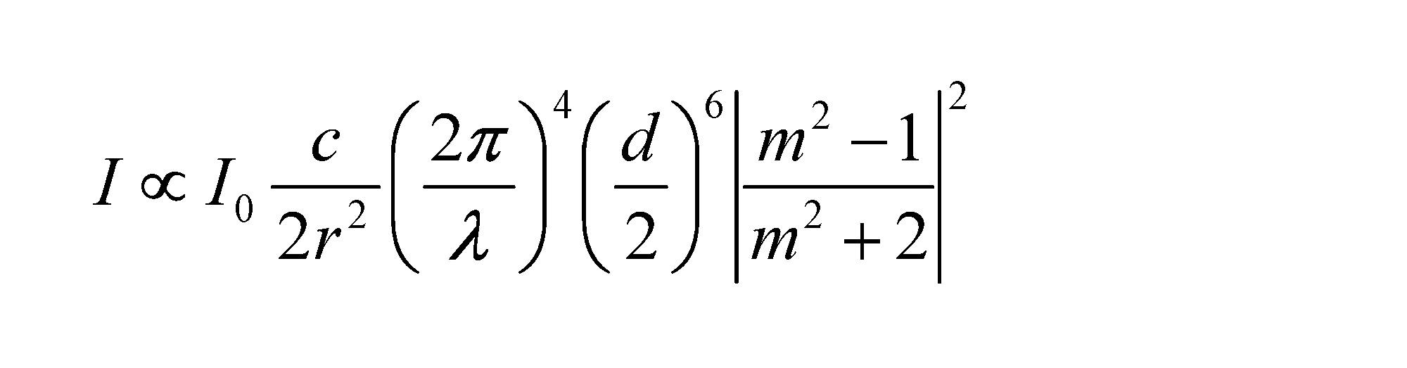
- the distance, ⁇ is the wavelength of the laser beam, d is the particle diameter, m is the relative refractive index of the particle with respect to the dispersion medium, and the scattered light intensity I that is the intensity of the scattered light and the incident light that is the intensity of the laser light Relational expression with light intensity I 0
- the relative refractive index m is obtained from the above, and absorption correction is performed to determine the material of the particles.
- the material of the particles can be discriminated along with the measurement of the particle diameter of the particles in the line.
- the dispersion medium flows along the axis in the column
- the camera is arranged with its optical axis oriented in a direction perpendicular to the axis
- the image analysis unit further includes the particles
- the displacement may be obtained by subtracting the moving component due to the flow velocity of the dispersion medium from the moving component in the direction along the axis in the image.
- the particle diameter can be measured even when the dispersion medium in the line is flowing.
- the image analysis unit further obtains a vertical movement component and a horizontal movement component in the image of the corresponding particle, and the calculation unit calculates a root mean square value of the vertical movement component and the horizontal movement component.
- the particle diameter may be calculated only for the corresponding particles having a difference or ratio of root mean square values of moving components in the direction within a predetermined value. According to this invention, even if it contains a plurality of types of particles having different densities that are intended to fall or float by gravity in the dispersion medium, only about the types of particles having a certain density with respect to the density of the dispersion medium. Particle size can be measured.
- the particle size measuring method is a particle size measuring method for measuring the particle size of particles that perform Brownian motion in the dispersion medium in the column, and includes imaging while irradiating the column with laser light.
- a step of imaging the dispersion medium in the column an image analysis step of obtaining displacement of corresponding particles from at least a plurality of images captured at a predetermined time interval ⁇ t, k B is a Boltzmann constant, T is an absolute temperature, a calculation step of calculating the particle diameter since k B T / 3 ⁇ d is proportional to the mean square value of the displacement, where ⁇ is the viscosity coefficient of the dispersion medium and d is the particle diameter.
- the image analysis step further includes a step of obtaining scattered light intensity and number concentration of the plurality of particles from the image, and the calculation step includes c from the number concentration and r from the particle.
- the distance to the camera ⁇ is the wavelength of the laser light
- d is the particle diameter
- m is the relative refractive index of the particle with respect to the dispersion medium
- the scattered light intensity I which is the intensity of the scattered light
- the method may further include a step of determining the material of the particles by obtaining the relative refractive index m from the above and correcting the absorption. According to this invention, the material of the particles can be discriminated along with the measurement of the particle diameter of the particles in the line.
- the dispersion medium is caused to flow along the axis in the column, and the camera is disposed with its optical axis oriented in a direction perpendicular to the axis, and the image analysis step further includes the particles
- the displacement may be obtained by subtracting the moving component due to the flow velocity of the dispersion medium from the moving component in the direction along the axis in the image.
- the particle diameter can be measured even when the dispersion medium in the line is flowing.
- the image analysis step further determines a vertical movement component and a horizontal movement component of the corresponding particle in the image, and the calculation step includes a root mean square value of the vertical movement component and the horizontal movement component.
- the particle diameter may be calculated only for the corresponding particles having a difference or ratio of root mean square values of moving components in the direction within a predetermined value. According to this invention, even if it contains a plurality of types of particles having different densities that are intended to fall or float by gravity in the dispersion medium, only about the types of particles having a certain density with respect to the density of the dispersion medium. Particle size can be measured.
- a particle diameter measuring apparatus 1 includes a transparent column 2 that can accommodate therein a dispersion medium in which particles are dispersed, and a laser beam irradiation unit 3 that can irradiate the particles in the column 2 with laser beams. And an imaging unit 4 including a camera 4 ′ that images the inside of the column 2, and an analysis unit 5 that performs calculations for analyzing an image obtained by the imaging unit 4 and calculating a particle diameter. Details of the column 2 will be described later. Here, it is assumed that the X axis, the Y axis, and the Z axis are determined so that the X axis is directed horizontally and the Y axis is directed vertically downward.
- the laser beam irradiation unit 3 is arranged so that the scattered light from the particles in the dispersion medium can be easily captured by the camera 4 ', that is, the intensity of the scattered light can be measured more strongly, and is emitted in this embodiment.
- the optical axis of the laser beam is inclined with respect to the axis 2 ′ of the column 2.
- the intensity of the scattered light is measured more strongly by using laser light with a short wavelength or using laser light with high intensity so as to increase the sensitivity of the camera 4 '. It is preferable to make it possible.
- the camera 4 ′ of the imaging unit 4 can continuously image the dispersion medium in the column 2 at a predetermined time interval ⁇ t from the Z-axis direction perpendicular to the axis 2 ′ of the column 2. That is, the camera 4 ′ is arranged with its optical axis perpendicular to the axis 2 ′, and can capture an image on the XY plane parallel to the axis 2 ′ as a moving image. Each captured image is recorded as a moving image with a predetermined time interval ⁇ t as one frame.
- a microscope camera, a CCD camera, a CMOS, or the like can be used as the camera 4 '.
- the camera 4 ′ is set so as to sufficiently brighten the image of the particles in the dispersion medium to be imaged by the scattered light, for example, by extending the shutter time in accordance with the range of the particle diameter of the particles to be measured. Is preferred. At this time, the shutter time to be set must not exceed a predetermined time interval ⁇ t (a time corresponding to one frame as a moving image).
- the analysis unit 5 is connected to the imaging unit 4 and performs image analysis and calculation of the captured image.
- the particle diameter is measured by such image analysis and calculation to discriminate the material of the particle, details of which will be described later.
- the column 2 serves as a flow path through which a dispersion medium in which particles are dispersed is passed along the axis 2 '.
- the direction of the X-axis and the Y-axis with respect to the gravity direction has been described above, the direction of each axis can be arbitrarily determined with respect to the gravity direction.
- a dispersion medium in which particles to be measured are dispersed is passed through the column 2 along the axis 2 '.
- the shape of the column 2 the viscosity of the dispersion medium, and the flow velocity are adjusted so that the flow of the dispersion medium is a laminar flow.
- the laser beam is irradiated from the laser beam irradiation unit 3 to the dispersion medium in the column 2 and the dispersion medium is imaged by the camera 4 '(S1).
- the images obtained as described above are a series of images captured at a predetermined time interval ⁇ t, that is, moving images, and each image has a Y axis parallel to the axis 2 ′ of the column 2 that is the flow direction of the dispersion medium. And an image on the XY plane. That is, as shown in FIG. 3, a Y axis parallel to the flow direction and an X axis perpendicular thereto can be set on the captured image.
- image analysis is performed (S2).
- the position of the particle corresponding to one particle is obtained on the image, and the position of the corresponding particle on the next image separated by the time interval ⁇ t is obtained. From the difference between these positions, the displacement of the corresponding particle between the two images is obtained. Details of how to obtain such displacement will be described later. Such an operation is performed between each image in a series of images.
- the material discrimination which will be described later, the intensity of scattered light at the corresponding particle is measured and recorded on the image, and the number density of particles is calculated by counting the number of particle images within a predetermined range. To do. The number density may be measured using a particle counter.
- the particle diameter is calculated (S3).
- the particle diameter is calculated from the fact that the average value of the square of the obtained displacement is proportional to the diffusion coefficient D.
- the analysis unit 5 records the intensity of scattered light from each corresponding particle on the image.
- the calculated particle diameter is sufficiently small with respect to the wavelength of the laser beam that is incident light, that is, when Rayleigh scattering occurs, the following equation is established.
- c is the number concentration of the particles
- r is the distance from the particles to the camera 4 ′
- ⁇ is the wavelength of the incident light
- I is the intensity of the scattered light
- I 0 is the intensity of the incident light
- d is the particle diameter of the corresponding particle.
- M is represented by the relative refractive index of the particles with respect to the dispersion medium. For this reason, even if it has the same particle diameter, m differs because the material of particle
- the relative refractive index m can be obtained from the distance r to the camera 4 ′ that changes for one particle and the intensity I of the scattered light.
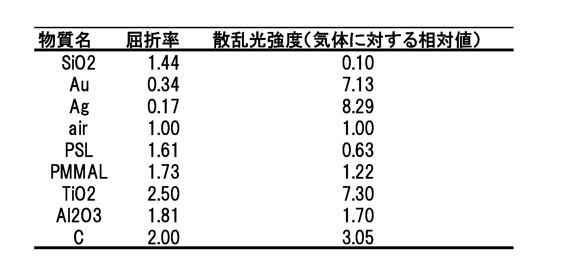
- the relative refractive index m is corrected by the imaginary term for absorption, and the known refractive index as shown in Table 1 is referred to by this absorption correction, so that the material can be discriminated together with the measurement of the particle diameter. Is possible. Note that r can be measured or back-calculated / evaluated with a known sample for the particle diameter and Rayleigh ratio.
- the particle diffusion is influenced by the flow, and it is difficult to calculate an accurate particle diameter from the moving distance by the diffusion. Therefore, in the present embodiment, as described below, the particle diameter is calculated by obtaining the displacement so as not to be affected by the flow.
- the Y axis parallel to the flow direction of the dispersion medium and the X axis perpendicular thereto can be set for each image.
- the influence of the flow of the dispersion medium is not given to the displacement. In this way, the movement component ⁇ x is obtained between the images of a series of images.
- the particle size (S3) which is the square of the average value of the moving components .delta.x obtained by [( ⁇ x) 2] obtaining a diffusion coefficient D 1.
- the particles areotropically move in all directions of the X axis, the Y axis, and the Z axis. Assuming that there is no influence of the flow of the dispersion medium and gravity, which will be described later, if the trajectory of the corresponding particle is traced on the image for a sufficient time, the mean value of the square of the moving component is the same for all directions.
- each image can have a Y axis parallel to the flow direction of the dispersion medium and an X axis perpendicular thereto.
- the displacement is obtained by a movement component ⁇ x parallel to the X axis and a movement component ⁇ y parallel to the Y axis.
- the movement component ⁇ y is obtained by correcting the movement due to the flow on the image. That is, a moving component ⁇ y is obtained by subtracting an amount obtained by multiplying the flow rate of the dispersion medium by ⁇ t from the moving amount in the Y-axis direction on the image. Thereby, the influence of the flow of the dispersion medium is not given to the moving component ⁇ x and the moving component ⁇ y. In this way, the movement component ⁇ x and the movement component ⁇ y are obtained between the images of the series of images. In this case, the flow rate of the dispersion medium is obtained by attaching a flow sensor to the column 2.
- the diffusion coefficient is calculated by [( ⁇ x) 2 ] which is the average value of the square of the moving component ⁇ x and [( ⁇ y) 2 ] which is the average value of the square of the moving component ⁇ y. determine the D 2.
- [( ⁇ x) 2 ] + [( ⁇ y ) 2 ] can be used as an average value of the square of the two-dimensional displacement, and a two-dimensional diffusion coefficient can be obtained.
- the particle diameter is calculated from the movement based on diffusion, it is almost unnecessary to control the detection angle of the scattered light, and the scattering in a wider scattering angle range can be integrated.
- the particle diameter can be measured with sufficient scattered light detection intensity.
- the intensity of the scattered light may be increased by using a plurality of laser light irradiation units 3.
- the particle size and the material of the particles in the dispersion medium can be identified in a short time and easily, and the particles and bubbles in the production line that were impossible with the material synthesis line monitoring and quality control, particle counter Various applications such as identification of impurities and evaluation of contamination in pharmaceutical production lines can be expected.
- a dispersion liquid in which polystyrene latex particles (diameter: about 100 nm) were dispersed was passed through the column 2 and the particle diameter was measured.
- the measured particle diameter (diameter) and the distribution of the number thereof are shown in FIG.
- FIG. 4B shows the measurement result when a two-dimensional diffusion coefficient is used.
- the measurement result in the case where the movement due to the flow on the image is not corrected is shown in FIG.
- FIGS. 4 (a) and 4 (b) a distribution centering on a particle size of 100 nm was measured both when a one-dimensional diffusion coefficient was used and when a two-dimensional diffusion coefficient was used.
- the variation width is smaller in the latter. This is considered to be greatly influenced by the flow state of the dispersion medium in the column 2, particularly whether the flow state is a laminar flow.
- FIG. 4C it is possible to reduce the error in the measured particle diameter by performing correction to reduce the movement due to the flow.
- the silica particles s, the polystyrene latex particles p, and the gold particles g have different scattered light intensities, although there are some overlapping distributions in the scattered light intensity. That is, the material can be identified by referring to the known refractive index.
- the particle to be measured is selected by the influence on the Brownian motion due to the density difference between the dispersion medium in which the particle is dispersed and the particle.
- To measure the particle size A method for selecting such particles will be described.
- particles having the same density that is, the same material can be selected from the difference or ratio between [( ⁇ x) 2 ] and [( ⁇ y) 2 ].
- the average value of ⁇ y is positive (downward in FIG. 6)
- the average value of ⁇ y is negative (upward in FIG. 6). This also makes it possible to select the particles.
- grains of a specific density can be selected by using the dispersion
- the Y axis only needs to be able to measure the movement of particles that are affected by the density difference from the dispersion medium, and therefore does not necessarily have to be oriented in the vertical direction, and may have an inclination with respect to the horizontal direction. That is, it is preferable that the optical axis of the camera 4 ′ be in the horizontal direction, but it is sufficient if it has an inclination with respect to the vertical direction.
- the nano-sized particle material to be measured is a nano material having an average particle diameter of 10 to 1500 nm, and examples thereof include silica, polystyrene latex, and carbon black. Moreover, it is possible to measure not only nano-sized particles but also minute particles that can observe Brownian motion.
- the particle diameter can be measured by selecting the particle to be measured by the density difference. That is, if the particle to be measured is selected and the particle diameter is obtained, for example, only the particle diameter of the contained bubbles excluding the impurities in the dispersion medium can be correctly measured.
- the particle size of Measurement is possible. That is, the nutrient solution contains a large amount of contaminants, and only the particle diameter of the contained bubbles excluding the contaminants can be correctly measured.
- silica particles (about 300 nm: manufactured by Polyscience, trade name: Microspheres, catalog number 24321, lot number 603704, specific gravity 2.00) were prepared at a concentration of 0.0004 mg / mL. This dispersion was injected into the column 2 and the movement of the particles was measured by the method described above.
- the average value of the square of each of the movement component ⁇ x in the X-axis direction and the movement component ⁇ y in the Y-axis direction is 563, and the average particle size was 337 nm, and the particle size could be measured with high accuracy.
- polystyrene latex particles (about 300 nm: manufactured by JSR Corporation, trade name SC032-S, lot number 100928, specific gravity 1.054) were prepared to a concentration of 0.0002 mg / mL. This dispersion was injected into the column 2 and the movement of the particles was measured by the method described above. Further, silica particles (about 300 nm: manufactured by Polyscience, trade name Microspheres, catalog number 24321, lot number 603704, specific gravity 2.00) were further added to adjust the concentration to 0.0004 mg / mL, and the same measurement as above.
- samples used for measurement are polystyrene latex with sample names P100 and P300, silica (silicon dioxide) with sample names S100 and S300, and gold with sample name G100.
- the official diameter is determined by dynamic light scattering (DLS) or transmission electron microscope (TEM). These were dispersed in a dispersion medium composed of ultrapure water, and the average value of the square of the moving component in each of the X-axis direction and the Y-axis direction per second was determined by the method described above, and the results are shown in FIG.
- the polystyrene latex (P100 and P300) was about 1% higher than the X-axis direction in the Y-axis direction, but was almost the same value in both the X-axis direction and the Y-axis direction.
- the values in the Y-axis direction are clearly large for silica and gold.
- the values in the Y-axis direction were 3%, 15%, and 10% larger in S100, S300, and G100, respectively, than the values in the X-axis direction.
- the same density is obtained from the difference or ratio between the mean value [( ⁇ x) 2 ] of the square of the moving component in the horizontal direction and the mean value [( ⁇ y) 2 ] of the square of the moving component in the vertical direction.
- Particles can be selected. That is, the material can be determined. Each plot is an average value for 500 or more particles, and is displayed with a standard deviation.
Landscapes
- Chemical & Material Sciences (AREA)
- Dispersion Chemistry (AREA)
- Physics & Mathematics (AREA)
- Health & Medical Sciences (AREA)
- Life Sciences & Earth Sciences (AREA)
- Analytical Chemistry (AREA)
- Biochemistry (AREA)
- General Health & Medical Sciences (AREA)
- General Physics & Mathematics (AREA)
- Immunology (AREA)
- Pathology (AREA)
- Engineering & Computer Science (AREA)
- Signal Processing (AREA)
- Length Measuring Devices By Optical Means (AREA)
- Investigating Or Analysing Materials By Optical Means (AREA)
Abstract
Description
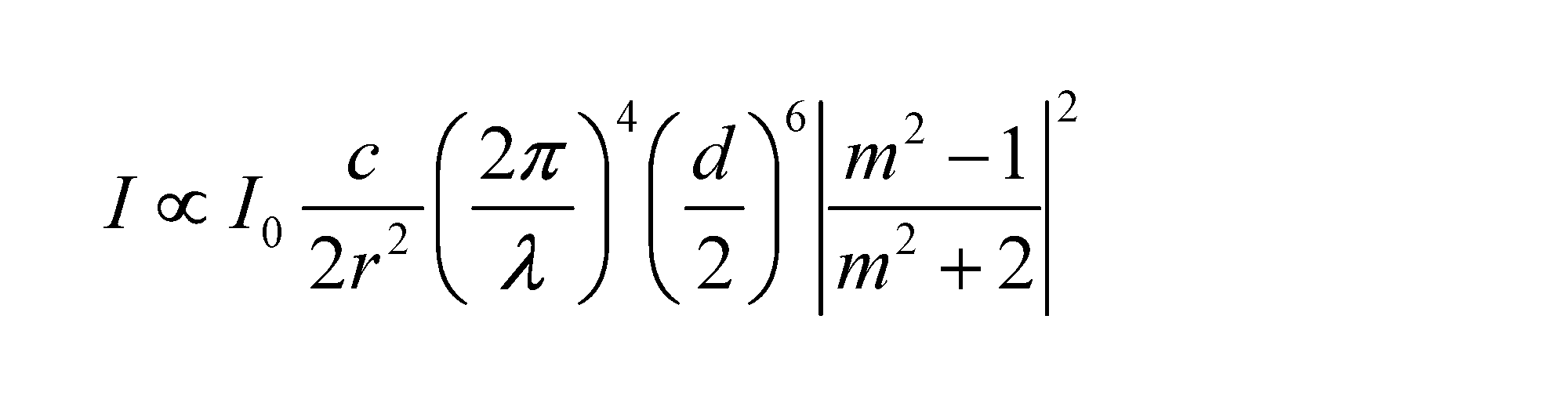

図1に示すように、粒子径計測装置1は粒子を分散させた分散媒を内部に収容し得る透明なカラム2と、カラム2内の粒子に対してレーザ光を照射できるレーザ光照射部3と、カラム2内を撮像するカメラ4’を含む撮像部4と、撮像部4により得た画像を解析して粒子径を算出するための計算を行う解析部5とを備える。カラム2の詳細については後述する。また、ここではX軸、Y軸及びZ軸が、X軸を水平方向、Y軸を鉛直方向下向きに向けるように定められているものとする。
次いで、カラム2内の分散媒に流速があるときの粒子径の計測方法について図2を用いて図1及び図3を参照しつつ説明する。
D=kBT/3πηd
となる。すなわち、上述した変位の2乗の平均値は、上式の右辺に比例する。かかる関係により対応粒子の計測された拡散による変位に相当する粒子径を算出することができる。かかる粒子径の算出方法の詳細についても後述する。
[(δx)2]=2D1Δt
によって1次元の拡散係数D1を算出する。さらに、kBをボルツマン定数、Tを絶対温度、ηを分散媒の粘性係数、dを粒子径とし、ストークス・アインシュタインの式、
D1=kBT/3πηd
によって粒子径を算出する。これにより、一連の画像の解析において、分散媒の流れの影響を受けないよう1次元の移動成分から1次元の変位を得て、かかる変位に基づいて、対応する1つの粒子の粒子径を算出できる。
[(δx)2]+[(δy)2]=4D2Δt
によって2次元の拡散係数D2を算出する。さらに、kBをボルツマン定数、Tを絶対温度、ηを分散媒の粘性係数、dを粒子径とし、ストークス・アインシュタインの式、
D2=kBT/3πηd
によって粒子径を算出する。これにより、一連の画像の解析において、分散媒の流れの影響を受けないよう2次元の移動成分から2次元の変位を得て、かかる変位に基づいて、対応する1つの粒子の粒子径を算出できる。
ポリスチレンラテックス粒子の粒子径を計測した例について、図4を用いて説明する。
各種粒子の粒子径計測に併せて、その材料を判別する例について図5を用いて説明する。
次いで、カラム2内の分散媒に流速がないときの粒子径の計測方法について図2を用いて図1及び図6を参照しつつ説明する。ここでは、カラム2に上下の閉じられたセル状のものを使用した。
シリカ粒子の粒子径の計測例について図7を用いて説明する。
上記同様に、ポリスチレンラテックス粒子の粒子径の計測例について図8を用いて説明する。
上記同様に、粒子径及び密度の異なる粒子を分散させたときの粒子径の計測例、及び、その材料を判別する例について図9及び図10を用いて説明する。ここでは、X軸方向及びY軸方向、すなわち水平方向及び鉛直方向のそれぞれの移動成分の2乗の平均値を計測した結果について説明する。
2 カラム
3 レーザ光照射部
4 撮像部
4’ カメラ
5 解析部
Claims (8)
- 分散媒中をブラウン運動する粒子の粒子径を計測する粒子径計測装置であって、
前記分散媒を内部に収容し得る透明なカラムと、
前記カラム内の分散媒にレーザ光を照射するレーザ光照射部と、
前記カラム内の前記分散媒を撮像するカメラを含む撮像部と、
所定時間間隔Δtで少なくとも複数撮像された画像から対応粒子の変位を求める画像解析部と、
kBをボルツマン定数、Tを絶対温度、ηを前記分散媒の粘性係数、dを前記粒子径とすると、前記変位の2乗平均値がkBT/3πηdに比例することから前記粒子径を算出する計算部と、を含むことを特徴とする粒子径計測装置。
- 前記画像解析部は、前記画像から複数の前記粒子の散乱光強度と個数濃度とを得て、
前記計算部はcを前記個数濃度、rを前記粒子から前記カメラまでの距離、λを前記レーザ光の波長、dを前記粒子径、mを前記分散媒に対する前記粒子の相対屈折率として、前記散乱光の強度である散乱光強度Iと前記レーザ光の強度である入射光強度I0との関係式
から前記相対屈折率mを求め吸収補正して前記粒子の材料を判別することを特徴とする請求項1記載の粒子径計測装置。
- 前記分散媒を前記カラム内の軸線に沿って流すとともに、
前記カメラはその光軸を前記軸線に垂直となる方向に向けて配置されており、
前記画像解析部はさらに前記粒子の前記画像における前記軸線に沿った方向の移動成分から前記分散媒の流速による移動成分を減じて前記変位を求めることを特徴とする請求項1又は2に記載の粒子径計測装置。 - 前記画像解析部はさらに前記対応粒子の前記画像における鉛直方向の移動成分及び水平方向の移動成分を求め、
前記計算部は前記鉛直方向の移動成分の2乗平均値及び前記水平方向の移動成分の2乗平均値の差又は比を所定値内とする前記対応粒子についてのみ前記粒子径を算出することを特徴とする請求項1記載の粒子径計測装置。 - カラム内の分散媒中をブラウン運動する粒子の粒子径を計測する粒子径計測方法であって、
前記カラム内にレーザ光を照射しながらカメラを含む撮像部によって、前記カラム内の前記分散媒を撮像するステップと、
所定時間間隔Δtで少なくとも複数撮像された画像から対応粒子の変位を求める画像解析ステップと、
kBをボルツマン定数、Tを絶対温度、ηを前記分散媒の粘性係数、dを前記粒子径として、kBT/3πηdが前記変位の2乗平均値に比例することから前記粒子径を算出する計算ステップと、を含むことを特徴とする粒子径計測方法。 - 前記画像解析ステップは、前記画像から複数の前記粒子の散乱光強度と個数濃度とを得るステップをさらに含み、
前記計算ステップは、cを前記個数濃度、rを前記粒子から前記カメラまでの距離、λを前記レーザ光の波長、dを前記粒子径、mを前記分散媒に対する前記粒子の相対屈折率として、前記散乱光の強度である散乱光強度Iと前記レーザ光の強度である入射光強度I0との関係式
から前記相対屈折率mを求め吸収補正して前記粒子の材料を判別するステップをさらに含むことを特徴とする請求項5記載の粒子径計測方法。
- 前記分散媒を前記カラム内の軸線に沿って流すとともに、
前記カメラはその光軸を前記軸線に垂直となる方向に向けて配置されており、
前記画像解析ステップはさらに前記粒子の前記画像における前記軸線に沿った方向の移動成分から前記分散媒の流速による移動成分を減じて前記変位を求めることを特徴とする請求項5又は6に記載の粒子径計測方法。 - 前記画像解析ステップはさらに前記対応粒子の前記画像における鉛直方向の移動成分及び水平方向の移動成分を求め、
前記計算ステップは前記鉛直方向の移動成分の2乗平均値及び前記水平方向の移動成分の2乗平均値の差又は比を所定値内とする前記対応粒子についてのみ前記粒子径を算出することを特徴とする請求項5記載の粒子径計測方法。
Priority Applications (3)
| Application Number | Priority Date | Filing Date | Title |
|---|---|---|---|
| JP2017510133A JP6687951B2 (ja) | 2015-03-30 | 2016-03-30 | 粒子径計測方法及びその装置 |
| US15/561,269 US10234370B2 (en) | 2015-03-30 | 2016-03-30 | Particle size measuring method and device |
| EP16773012.6A EP3279636B1 (en) | 2015-03-30 | 2016-03-30 | Particle size measuring method and device |
Applications Claiming Priority (4)
| Application Number | Priority Date | Filing Date | Title |
|---|---|---|---|
| JP2015-069016 | 2015-03-30 | ||
| JP2015069016 | 2015-03-30 | ||
| JP2015-184161 | 2015-09-17 | ||
| JP2015184161 | 2015-09-17 |
Publications (1)
| Publication Number | Publication Date |
|---|---|
| WO2016159131A1 true WO2016159131A1 (ja) | 2016-10-06 |
Family
ID=57004334
Family Applications (1)
| Application Number | Title | Priority Date | Filing Date |
|---|---|---|---|
| PCT/JP2016/060479 Ceased WO2016159131A1 (ja) | 2015-03-30 | 2016-03-30 | 粒子径計測方法及びその装置 |
Country Status (4)
| Country | Link |
|---|---|
| US (1) | US10234370B2 (ja) |
| EP (1) | EP3279636B1 (ja) |
| JP (2) | JP6687951B2 (ja) |
| WO (1) | WO2016159131A1 (ja) |
Cited By (21)
| Publication number | Priority date | Publication date | Assignee | Title |
|---|---|---|---|---|
| WO2018105605A1 (ja) * | 2016-12-06 | 2018-06-14 | 国立研究開発法人産業技術総合研究所 | 流速分布計測方法及び粒径計測方法 |
| WO2018190162A1 (ja) | 2017-04-14 | 2018-10-18 | リオン株式会社 | 粒子測定装置および粒子測定方法 |
| JP2018179971A (ja) * | 2017-04-14 | 2018-11-15 | リオン株式会社 | 粒子測定装置および粒子測定方法 |
| CN108956631A (zh) * | 2018-04-21 | 2018-12-07 | 广东明路电力电子有限公司 | 石墨烯检验设备及其检验方法 |
| CN109269429A (zh) * | 2018-06-15 | 2019-01-25 | 苏州高通新材料科技有限公司 | 二维材料平均片径检测方法、装置及数量获取方法、装置 |
| WO2020054466A1 (ja) * | 2018-09-12 | 2020-03-19 | 国立研究開発法人産業技術総合研究所 | 微粒子観察装置及び微粒子観察方法 |
| WO2020071306A1 (ja) | 2018-10-04 | 2020-04-09 | 国立研究開発法人産業技術総合研究所 | 粒子測定装置、較正方法、および測定装置 |
| JP2020173244A (ja) * | 2019-04-09 | 2020-10-22 | 株式会社日立製作所 | 粒子サイズ測定装置および測定方法 |
| JP2021508058A (ja) * | 2017-12-20 | 2021-02-25 | インプロセス アイピー ビー.ブイ.Inprocess Ip B.V. | 流動下のナノ懸濁液のインプロセス粒径測定のための方法および装置 |
| WO2021132017A1 (ja) | 2019-12-27 | 2021-07-01 | リオン株式会社 | 粒子測定装置 |
| JP2021101153A (ja) * | 2019-12-06 | 2021-07-08 | 大平研究所株式会社 | 微細気泡分散液の測定方法及び測定システム |
| US11112344B2 (en) | 2019-03-08 | 2021-09-07 | Kioxia Corporation | Particle measuring method and detection liquid |
| WO2021235169A1 (ja) * | 2020-05-20 | 2021-11-25 | 国立研究開発法人産業技術総合研究所 | 個数基準粒子径分布計測方法及び計測システム |
| JP2022517873A (ja) * | 2019-03-23 | 2022-03-10 | ホリバ インスツルメンツ インコーポレイテッド | コロイド中のナノ粒子のサイズを決定するための改良された方法 |
| JP2022520504A (ja) * | 2019-02-12 | 2022-03-30 | クリストフ、ランハンマー | 流体中の粒子の存在を検出するシステムおよび方法 |
| JPWO2022153633A1 (ja) * | 2021-01-18 | 2022-07-21 | ||
| WO2022163230A1 (ja) * | 2021-01-26 | 2022-08-04 | 株式会社堀場製作所 | 粒子径推定方法、学習モデル生成方法、粒子径推定装置、及びコンピュータプログラム |
| JPWO2023139741A1 (ja) * | 2022-01-21 | 2023-07-27 | ||
| WO2023181438A1 (ja) * | 2022-03-24 | 2023-09-28 | 株式会社東芝 | 粒子計測システム、および、粒子計測方法 |
| WO2025089267A1 (ja) * | 2023-10-27 | 2025-05-01 | 株式会社堀場製作所 | 動的光散乱式粒子径分布測定装置、動的光散乱式粒子径分布測定方法及び動的光散乱式粒子径分布測定プログラム |
| WO2025134693A1 (ja) * | 2023-12-19 | 2025-06-26 | 富士フイルム株式会社 | 光測定方法、及び光測定装置 |
Families Citing this family (15)
| Publication number | Priority date | Publication date | Assignee | Title |
|---|---|---|---|---|
| TWI582408B (zh) | 2011-08-29 | 2017-05-11 | 安美基公司 | 用於非破壞性檢測-流體中未溶解粒子之方法及裝置 |
| US10088660B2 (en) * | 2017-02-10 | 2018-10-02 | Amgen Inc. | Imaging system for counting and sizing particles in fluid-filled vessels |
| GB2559964A (en) * | 2017-02-16 | 2018-08-29 | Her Majesty In Right Of Canada As Represented By The Mini Of Natural Resources | Methods for measuring properties of rock pieces |
| WO2019230628A1 (ja) | 2018-06-01 | 2019-12-05 | 株式会社堀場製作所 | 粒子径分布測定装置及び粒子径分布測定装置用プログラム |
| TWI700489B (zh) * | 2018-10-29 | 2020-08-01 | 林修安 | 即時廢棄物品質檢測裝置以及廢棄物回收裝置與方法 |
| US11175212B2 (en) * | 2019-03-31 | 2021-11-16 | Agilent Technologies, Inc. | Mid-infrared scanning system for analyzing particulates |
| KR102333898B1 (ko) * | 2019-04-09 | 2021-12-01 | 가부시끼가이샤 히다치 세이사꾸쇼 | 입자 사이즈 측정 장치 및 측정 방법 |
| JP7421968B2 (ja) * | 2020-03-17 | 2024-01-25 | リオン株式会社 | 粒子測定装置及び粒子測定方法 |
| CN111562201B (zh) * | 2020-05-28 | 2024-06-14 | 清华大学 | 固态酿造制酒颗粒状原料粒度在线测量装置和方法 |
| CA3199098A1 (en) | 2020-10-21 | 2022-04-28 | Athanor Biosciences, Inc. | Size-based detection and quantification of functional bio-nanoparticles |
| KR102927687B1 (ko) * | 2021-05-07 | 2026-02-13 | 오다이라 래보로토리 캄파니 | 미세 기포 분산액의 측정 방법 및 측정 시스템 |
| CN113433042A (zh) * | 2021-06-25 | 2021-09-24 | 国家纳米科学中心 | 纳米颗粒检测微流控芯片和应用 |
| CN113654958A (zh) * | 2021-09-09 | 2021-11-16 | 珠海真理光学仪器有限公司 | 一种测量颗粒材料中超大颗粒含量的装置和方法 |
| EP4266056A1 (en) | 2022-04-21 | 2023-10-25 | Athanor Biosciences, Inc. | Size-based detection and quantification of functional bio-nanoparticles |
| JP7855292B1 (ja) * | 2026-01-29 | 2026-05-08 | 株式会社シュヴァルベル | 粒子分析システムの較正方法およびプログラム |
Citations (4)
| Publication number | Priority date | Publication date | Assignee | Title |
|---|---|---|---|---|
| JPS5397489A (en) * | 1977-02-05 | 1978-08-25 | Jujo Seisakusho | Measuring element for grain size distribution of aeroosol and its manufacture |
| JP2003270261A (ja) * | 2002-03-18 | 2003-09-25 | National Institute Of Advanced Industrial & Technology | 局所空間平均粒子追跡法 |
| JP2007322329A (ja) * | 2006-06-02 | 2007-12-13 | Univ Of Tsukuba | 粒子特性計測装置および粒子特性計測方法 |
| JP2009210584A (ja) * | 2008-03-03 | 2009-09-17 | Agilent Technol Inc | 工程内で小粒子の粒径分布を計算する方法及びシステム |
Family Cites Families (9)
| Publication number | Priority date | Publication date | Assignee | Title |
|---|---|---|---|---|
| US4866639A (en) * | 1987-03-09 | 1989-09-12 | University Of Illinois | Method and apparatus for determining the direction of motion in multiple exposure velocimetry |
| JP3301658B2 (ja) | 1993-08-04 | 2002-07-15 | ミクニキカイ株式会社 | 流体中の微粒子の粒径計測方法および装置 |
| JP2002022642A (ja) * | 2000-07-07 | 2002-01-23 | Horiba Ltd | 動的光散乱式粒径分布測定装置および粒径分布の測定方法 |
| US20070229823A1 (en) * | 2006-03-31 | 2007-10-04 | Intel Corporation | Determination of the number concentration and particle size distribution of nanoparticles using dark-field microscopy |
| JP4863083B2 (ja) | 2007-04-12 | 2012-01-25 | 国立大学法人電気通信大学 | 粒径計測装置 |
| JP2009276106A (ja) * | 2008-05-13 | 2009-11-26 | Nitta Haas Inc | 微粒子計測装置 |
| JP2010060544A (ja) | 2008-09-02 | 2010-03-18 | Keisuke Fukui | ブラウン粒子を用いた粘度および粒子径分布の測定方法および測定装置 |
| AT515577B1 (de) * | 2014-03-12 | 2018-06-15 | Anton Paar Gmbh | Gemeinsamer Strahlungspfad zum Ermitteln von Partikel-information durch Direktbildauswertung und durch Differenzbildanalyse |
| US10101256B2 (en) * | 2015-02-12 | 2018-10-16 | National University Corporation Kyoto Institute Of Technology | Ultrasonic particle size measurement device and ultrasonic measurement device |
-
2016
- 2016-03-30 WO PCT/JP2016/060479 patent/WO2016159131A1/ja not_active Ceased
- 2016-03-30 JP JP2017510133A patent/JP6687951B2/ja active Active
- 2016-03-30 EP EP16773012.6A patent/EP3279636B1/en active Active
- 2016-03-30 US US15/561,269 patent/US10234370B2/en active Active
-
2020
- 2020-03-25 JP JP2020054214A patent/JP6976605B2/ja active Active
Patent Citations (4)
| Publication number | Priority date | Publication date | Assignee | Title |
|---|---|---|---|---|
| JPS5397489A (en) * | 1977-02-05 | 1978-08-25 | Jujo Seisakusho | Measuring element for grain size distribution of aeroosol and its manufacture |
| JP2003270261A (ja) * | 2002-03-18 | 2003-09-25 | National Institute Of Advanced Industrial & Technology | 局所空間平均粒子追跡法 |
| JP2007322329A (ja) * | 2006-06-02 | 2007-12-13 | Univ Of Tsukuba | 粒子特性計測装置および粒子特性計測方法 |
| JP2009210584A (ja) * | 2008-03-03 | 2009-09-17 | Agilent Technol Inc | 工程内で小粒子の粒径分布を計算する方法及びシステム |
Non-Patent Citations (4)
| Title |
|---|
| DRAGOVIC, R.A. ET AL.: "Sizing and phenotyping of cellular vesicles using Nanoparticle Tracking Analysis", NANOMEDICINE: NANOTECHNOLOGY, BIOLOGY, AND MEDICINE, vol. 7, no. Issue 6, December 2011 (2011-12-01), pages 780 - 788, XP055040874 * |
| ELIM, H.I. ET AL.: "Refractive Index Control and Rayleigh Scattering Properties of Transparent TiO2 Nanohybrid Polymer", JOURNAL OF PHYSICAL CHEMISTRY B, vol. 113, no. 30, pages 10143 - 10148, XP055315369 * |
| See also references of EP3279636A4 * |
| YOSHINORI TAKIKAWA ET AL.: "Brownian motion of particles under steady shear flow", THE PHYSICAL SOCIETY OF JAPAN KOEN YOSHISHU, vol. 69, no. 2, 22 August 2014 (2014-08-22), pages 198, XP009506601 * |
Cited By (55)
| Publication number | Priority date | Publication date | Assignee | Title |
|---|---|---|---|---|
| GB2571477A (en) * | 2016-12-06 | 2019-08-28 | Aist | Flow velocity distribution measuring method and particle size measuring method |
| GB2571477B (en) * | 2016-12-06 | 2022-05-11 | Aist | Flow velocity distribution measuring method and particle size measuring method |
| WO2018105605A1 (ja) * | 2016-12-06 | 2018-06-14 | 国立研究開発法人産業技術総合研究所 | 流速分布計測方法及び粒径計測方法 |
| JPWO2018105605A1 (ja) * | 2016-12-06 | 2019-10-24 | 国立研究開発法人産業技術総合研究所 | 流速分布計測方法及び粒径計測方法 |
| EP3611492A4 (en) * | 2017-04-14 | 2020-05-13 | Rion Co., Ltd. | PARTICLE MEASURING DEVICE AND PARTICLE MEASURING METHOD |
| CN110573855A (zh) * | 2017-04-14 | 2019-12-13 | 理音株式会社 | 粒子测量装置和粒子测量方法 |
| KR20200002817A (ko) | 2017-04-14 | 2020-01-08 | 리온 가부시키가이샤 | 입자 측정 장치 및 입자 측정 방법 |
| KR102482542B1 (ko) * | 2017-04-14 | 2022-12-28 | 리온 가부시키가이샤 | 입자 측정 장치 및 입자 측정 방법 |
| JP2018179971A (ja) * | 2017-04-14 | 2018-11-15 | リオン株式会社 | 粒子測定装置および粒子測定方法 |
| US10837890B2 (en) | 2017-04-14 | 2020-11-17 | Rion Co., Ltd. | Particle measuring device and particle measuring method |
| WO2018190162A1 (ja) | 2017-04-14 | 2018-10-18 | リオン株式会社 | 粒子測定装置および粒子測定方法 |
| JP7710066B2 (ja) | 2017-12-20 | 2025-07-17 | インプロセス アイピー ビー.ブイ. | 流動下のナノ懸濁液のインプロセス粒径測定のための方法および装置 |
| JP2024052844A (ja) * | 2017-12-20 | 2024-04-12 | インプロセス アイピー ビー.ブイ. | 流動下のナノ懸濁液のインプロセス粒径測定のための方法および装置 |
| JP2021508058A (ja) * | 2017-12-20 | 2021-02-25 | インプロセス アイピー ビー.ブイ.Inprocess Ip B.V. | 流動下のナノ懸濁液のインプロセス粒径測定のための方法および装置 |
| CN108956631A (zh) * | 2018-04-21 | 2018-12-07 | 广东明路电力电子有限公司 | 石墨烯检验设备及其检验方法 |
| CN108956631B (zh) * | 2018-04-21 | 2021-07-30 | 广东明路电力电子有限公司 | 石墨烯检验设备及其检验方法 |
| CN109269429A (zh) * | 2018-06-15 | 2019-01-25 | 苏州高通新材料科技有限公司 | 二维材料平均片径检测方法、装置及数量获取方法、装置 |
| GB2589012B (en) * | 2018-09-12 | 2022-06-01 | Aist | Particulate observation device and particulate observation method |
| JPWO2020054466A1 (ja) * | 2018-09-12 | 2021-02-25 | 国立研究開発法人産業技術総合研究所 | 微粒子観察装置及び微粒子観察方法 |
| WO2020054466A1 (ja) * | 2018-09-12 | 2020-03-19 | 国立研究開発法人産業技術総合研究所 | 微粒子観察装置及び微粒子観察方法 |
| US11415500B2 (en) | 2018-09-12 | 2022-08-16 | National Institute Of Advanced Industrial Science And Technology | Particulate observation device and particulate observation method |
| GB2589012A (en) * | 2018-09-12 | 2021-05-19 | Aist | Particulate observation device and particulate observation method |
| US11774340B2 (en) | 2018-10-04 | 2023-10-03 | National Institute Of Advanced Industrial Science And Technology | Particle measuring device, calibration method, and measuring device |
| WO2020071306A1 (ja) | 2018-10-04 | 2020-04-09 | 国立研究開発法人産業技術総合研究所 | 粒子測定装置、較正方法、および測定装置 |
| JP7116419B2 (ja) | 2018-10-04 | 2022-08-10 | 国立研究開発法人産業技術総合研究所 | 粒子測定装置、較正方法、および測定装置 |
| TWI810375B (zh) * | 2018-10-04 | 2023-08-01 | 國立研究開發法人産業技術總合研究所 | 粒子測定裝置、校正方法以及測定裝置 |
| JP2020056743A (ja) * | 2018-10-04 | 2020-04-09 | 国立研究開発法人産業技術総合研究所 | 粒子測定装置、較正方法、および測定装置 |
| KR20210066809A (ko) | 2018-10-04 | 2021-06-07 | 고쿠리츠켄큐카이하츠호진 상교기쥬츠 소고켄큐쇼 | 입자 측정 장치, 교정 방법, 및 측정 장치 |
| KR102724822B1 (ko) | 2018-10-04 | 2024-10-31 | 고쿠리츠켄큐카이하츠호진 상교기쥬츠 소고켄큐쇼 | 입자 측정 장치, 교정 방법, 및 측정 장치 |
| JP2022520504A (ja) * | 2019-02-12 | 2022-03-30 | クリストフ、ランハンマー | 流体中の粒子の存在を検出するシステムおよび方法 |
| JP7269379B2 (ja) | 2019-02-12 | 2023-05-08 | クリストフ、ランハンマー | 流体中の粒子の存在を検出するシステムおよび方法 |
| US11112344B2 (en) | 2019-03-08 | 2021-09-07 | Kioxia Corporation | Particle measuring method and detection liquid |
| JP7182741B2 (ja) | 2019-03-23 | 2022-12-02 | ホリバ インスツルメンツ インコーポレイテッド | コロイド中のナノ粒子のサイズを決定するための改良された方法 |
| JP2022110137A (ja) * | 2019-03-23 | 2022-07-28 | ホリバ インスツルメンツ インコーポレイテッド | コロイド中のナノ粒子のサイズを決定するための改良された方法 |
| JP2022517873A (ja) * | 2019-03-23 | 2022-03-10 | ホリバ インスツルメンツ インコーポレイテッド | コロイド中のナノ粒子のサイズを決定するための改良された方法 |
| JP7105382B2 (ja) | 2019-03-23 | 2022-07-22 | ホリバ インスツルメンツ インコーポレイテッド | コロイド中のナノ粒子のサイズを決定するための改良された方法 |
| JP2020173244A (ja) * | 2019-04-09 | 2020-10-22 | 株式会社日立製作所 | 粒子サイズ測定装置および測定方法 |
| JP7328871B2 (ja) | 2019-04-09 | 2023-08-17 | 株式会社日立製作所 | 粒子サイズ測定装置および測定方法 |
| JP2021101153A (ja) * | 2019-12-06 | 2021-07-08 | 大平研究所株式会社 | 微細気泡分散液の測定方法及び測定システム |
| JP7334957B2 (ja) | 2019-12-06 | 2023-08-29 | 大平研究所株式会社 | 微細気泡分散液の測定方法及び測定システム |
| WO2021132017A1 (ja) | 2019-12-27 | 2021-07-01 | リオン株式会社 | 粒子測定装置 |
| US12265008B2 (en) | 2019-12-27 | 2025-04-01 | Rion Co., Ltd. | Particle measuring device |
| KR20220118396A (ko) | 2019-12-27 | 2022-08-25 | 리온 가부시키가이샤 | 입자 측정 장치 |
| WO2021235169A1 (ja) * | 2020-05-20 | 2021-11-25 | 国立研究開発法人産業技術総合研究所 | 個数基準粒子径分布計測方法及び計測システム |
| WO2022153633A1 (ja) * | 2021-01-18 | 2022-07-21 | 国立研究開発法人産業技術総合研究所 | 粒子密度計測方法及びその装置 |
| JPWO2022153633A1 (ja) * | 2021-01-18 | 2022-07-21 | ||
| WO2022163230A1 (ja) * | 2021-01-26 | 2022-08-04 | 株式会社堀場製作所 | 粒子径推定方法、学習モデル生成方法、粒子径推定装置、及びコンピュータプログラム |
| JPWO2023139741A1 (ja) * | 2022-01-21 | 2023-07-27 | ||
| WO2023139741A1 (ja) * | 2022-01-21 | 2023-07-27 | 株式会社日立ハイテク | 粒子計測装置 |
| JP7769016B2 (ja) | 2022-01-21 | 2025-11-12 | 株式会社日立ハイテク | 粒子計測装置 |
| WO2023181438A1 (ja) * | 2022-03-24 | 2023-09-28 | 株式会社東芝 | 粒子計測システム、および、粒子計測方法 |
| JP2023142064A (ja) * | 2022-03-24 | 2023-10-05 | 株式会社東芝 | 微小粒子計測システム、および、微小粒子計測方法 |
| JP7834528B2 (ja) | 2022-03-24 | 2026-03-24 | 株式会社東芝 | 微小粒子計測システム、および、微小粒子計測方法 |
| WO2025089267A1 (ja) * | 2023-10-27 | 2025-05-01 | 株式会社堀場製作所 | 動的光散乱式粒子径分布測定装置、動的光散乱式粒子径分布測定方法及び動的光散乱式粒子径分布測定プログラム |
| WO2025134693A1 (ja) * | 2023-12-19 | 2025-06-26 | 富士フイルム株式会社 | 光測定方法、及び光測定装置 |
Also Published As
| Publication number | Publication date |
|---|---|
| US10234370B2 (en) | 2019-03-19 |
| US20180120214A1 (en) | 2018-05-03 |
| JP6687951B2 (ja) | 2020-04-28 |
| EP3279636A4 (en) | 2018-12-05 |
| EP3279636A1 (en) | 2018-02-07 |
| JP2020109419A (ja) | 2020-07-16 |
| JP6976605B2 (ja) | 2021-12-08 |
| JPWO2016159131A1 (ja) | 2018-01-25 |
| EP3279636B1 (en) | 2022-05-18 |
Similar Documents
| Publication | Publication Date | Title |
|---|---|---|
| JP6976605B2 (ja) | 粒子径計測方法及びその装置 | |
| US20220334047A1 (en) | Method and device for determining features of particles by multiparametric capture of scattered light and extinction signals | |
| JP7009402B2 (ja) | コロイドの粒度分布を決定するシステム | |
| JP6867731B2 (ja) | 微粒子観察装置及び微粒子観察方法 | |
| CN102207443B (zh) | 一种颗粒粒度测量仪 | |
| JP6348187B2 (ja) | 散乱光を用いた粒子トラッキング解析(pta)法及びあらゆる液体中においてナノメートルオーダー大きさの粒子を検知及び識別するための装置 | |
| JP6596636B2 (ja) | 流速分布計測方法及び粒径計測方法 | |
| CN104390895B (zh) | 基于显微成像的图像灰度测量颗粒粒径的方法 | |
| US20070229823A1 (en) | Determination of the number concentration and particle size distribution of nanoparticles using dark-field microscopy | |
| CN104089858A (zh) | 一种颗粒粒度仪 | |
| JP2015520396A (ja) | 粒子特性評価 | |
| EP3862742B1 (en) | Particle measuring device, calibration method, and measuring device | |
| WO2011045961A1 (ja) | 粒径計測装置、及び粒径計測方法 | |
| De Temmerman et al. | Size measurement uncertainties of near-monodisperse, near-spherical nanoparticles using transmission electron microscopy and particle-tracking analysis | |
| JP2018004450A (ja) | 気泡径分布測定装置及び気泡径分布測定方法 | |
| JPS61159135A (ja) | 粒子解析装置 | |
| TW202136740A (zh) | 粒子測量裝置以及粒子測量方法 | |
| Khan | Dynamic light scattering | |
| Hansen et al. | Novel optical and statistical methods reveal colloid–wall interactions inconsistent with DLVO and Lifshitz theories | |
| CN108369169B (zh) | 用于测量胶体颗粒的生长或溶解动力学的装置和方法 | |
| CN113597546B (zh) | 确定胶体中纳米粒子尺寸的改进方法 | |
| WO2021235169A1 (ja) | 個数基準粒子径分布計測方法及び計測システム | |
| Schimek et al. | Challenges at Submicron Particle Characterisation: A Case Study Using Nanoparticle Tracking Analysis (NTA) | |
| CN201984011U (zh) | 一种颗粒粒度测量仪 | |
| JP5418383B2 (ja) | 粒度分布測定装置及びプログラム |
Legal Events
| Date | Code | Title | Description |
|---|---|---|---|
| 121 | Ep: the epo has been informed by wipo that ep was designated in this application |
Ref document number: 16773012 Country of ref document: EP Kind code of ref document: A1 |
|
| ENP | Entry into the national phase |
Ref document number: 2017510133 Country of ref document: JP Kind code of ref document: A |
|
| WWE | Wipo information: entry into national phase |
Ref document number: 15561269 Country of ref document: US |
|
| NENP | Non-entry into the national phase |
Ref country code: DE |
|
| REEP | Request for entry into the european phase |
Ref document number: 2016773012 Country of ref document: EP |