WO2016158187A1 - リチウムイオン電池用電極、リチウムイオン電池及びリチウムイオン電池用電極の製造方法 - Google Patents
リチウムイオン電池用電極、リチウムイオン電池及びリチウムイオン電池用電極の製造方法 Download PDFInfo
- Publication number
- WO2016158187A1 WO2016158187A1 PCT/JP2016/056568 JP2016056568W WO2016158187A1 WO 2016158187 A1 WO2016158187 A1 WO 2016158187A1 JP 2016056568 W JP2016056568 W JP 2016056568W WO 2016158187 A1 WO2016158187 A1 WO 2016158187A1
- Authority
- WO
- WIPO (PCT)
- Prior art keywords
- electrode
- lithium ion
- ion battery
- active material
- fibers
- Prior art date
Links
Images


Classifications
-
- H—ELECTRICITY
- H01—ELECTRIC ELEMENTS
- H01M—PROCESSES OR MEANS, e.g. BATTERIES, FOR THE DIRECT CONVERSION OF CHEMICAL ENERGY INTO ELECTRICAL ENERGY
- H01M4/00—Electrodes
- H01M4/02—Electrodes composed of, or comprising, active material
- H01M4/62—Selection of inactive substances as ingredients for active masses, e.g. binders, fillers
-
- H—ELECTRICITY
- H01—ELECTRIC ELEMENTS
- H01M—PROCESSES OR MEANS, e.g. BATTERIES, FOR THE DIRECT CONVERSION OF CHEMICAL ENERGY INTO ELECTRICAL ENERGY
- H01M10/00—Secondary cells; Manufacture thereof
- H01M10/05—Accumulators with non-aqueous electrolyte
- H01M10/052—Li-accumulators
- H01M10/0525—Rocking-chair batteries, i.e. batteries with lithium insertion or intercalation in both electrodes; Lithium-ion batteries
-
- H—ELECTRICITY
- H01—ELECTRIC ELEMENTS
- H01M—PROCESSES OR MEANS, e.g. BATTERIES, FOR THE DIRECT CONVERSION OF CHEMICAL ENERGY INTO ELECTRICAL ENERGY
- H01M4/00—Electrodes
- H01M4/02—Electrodes composed of, or comprising, active material
- H01M4/04—Processes of manufacture in general
- H01M4/0402—Methods of deposition of the material
- H01M4/0404—Methods of deposition of the material by coating on electrode collectors
-
- H—ELECTRICITY
- H01—ELECTRIC ELEMENTS
- H01M—PROCESSES OR MEANS, e.g. BATTERIES, FOR THE DIRECT CONVERSION OF CHEMICAL ENERGY INTO ELECTRICAL ENERGY
- H01M4/00—Electrodes
- H01M4/02—Electrodes composed of, or comprising, active material
- H01M4/04—Processes of manufacture in general
- H01M4/043—Processes of manufacture in general involving compressing or compaction
-
- H—ELECTRICITY
- H01—ELECTRIC ELEMENTS
- H01M—PROCESSES OR MEANS, e.g. BATTERIES, FOR THE DIRECT CONVERSION OF CHEMICAL ENERGY INTO ELECTRICAL ENERGY
- H01M4/00—Electrodes
- H01M4/02—Electrodes composed of, or comprising, active material
- H01M4/13—Electrodes for accumulators with non-aqueous electrolyte, e.g. for lithium-accumulators; Processes of manufacture thereof
- H01M4/139—Processes of manufacture
-
- H—ELECTRICITY
- H01—ELECTRIC ELEMENTS
- H01M—PROCESSES OR MEANS, e.g. BATTERIES, FOR THE DIRECT CONVERSION OF CHEMICAL ENERGY INTO ELECTRICAL ENERGY
- H01M4/00—Electrodes
- H01M4/02—Electrodes composed of, or comprising, active material
- H01M4/36—Selection of substances as active materials, active masses, active liquids
- H01M4/362—Composites
- H01M4/364—Composites as mixtures
-
- H—ELECTRICITY
- H01—ELECTRIC ELEMENTS
- H01M—PROCESSES OR MEANS, e.g. BATTERIES, FOR THE DIRECT CONVERSION OF CHEMICAL ENERGY INTO ELECTRICAL ENERGY
- H01M4/00—Electrodes
- H01M4/02—Electrodes composed of, or comprising, active material
- H01M4/36—Selection of substances as active materials, active masses, active liquids
- H01M4/362—Composites
- H01M4/366—Composites as layered products
-
- H—ELECTRICITY
- H01—ELECTRIC ELEMENTS
- H01M—PROCESSES OR MEANS, e.g. BATTERIES, FOR THE DIRECT CONVERSION OF CHEMICAL ENERGY INTO ELECTRICAL ENERGY
- H01M4/00—Electrodes
- H01M4/02—Electrodes composed of, or comprising, active material
- H01M4/62—Selection of inactive substances as ingredients for active masses, e.g. binders, fillers
- H01M4/624—Electric conductive fillers
-
- H—ELECTRICITY
- H01—ELECTRIC ELEMENTS
- H01M—PROCESSES OR MEANS, e.g. BATTERIES, FOR THE DIRECT CONVERSION OF CHEMICAL ENERGY INTO ELECTRICAL ENERGY
- H01M4/00—Electrodes
- H01M4/02—Electrodes composed of, or comprising, active material
- H01M2004/021—Physical characteristics, e.g. porosity, surface area
-
- H—ELECTRICITY
- H01—ELECTRIC ELEMENTS
- H01M—PROCESSES OR MEANS, e.g. BATTERIES, FOR THE DIRECT CONVERSION OF CHEMICAL ENERGY INTO ELECTRICAL ENERGY
- H01M2220/00—Batteries for particular applications
- H01M2220/20—Batteries in motive systems, e.g. vehicle, ship, plane
-
- Y—GENERAL TAGGING OF NEW TECHNOLOGICAL DEVELOPMENTS; GENERAL TAGGING OF CROSS-SECTIONAL TECHNOLOGIES SPANNING OVER SEVERAL SECTIONS OF THE IPC; TECHNICAL SUBJECTS COVERED BY FORMER USPC CROSS-REFERENCE ART COLLECTIONS [XRACs] AND DIGESTS
- Y02—TECHNOLOGIES OR APPLICATIONS FOR MITIGATION OR ADAPTATION AGAINST CLIMATE CHANGE
- Y02E—REDUCTION OF GREENHOUSE GAS [GHG] EMISSIONS, RELATED TO ENERGY GENERATION, TRANSMISSION OR DISTRIBUTION
- Y02E60/00—Enabling technologies; Technologies with a potential or indirect contribution to GHG emissions mitigation
- Y02E60/10—Energy storage using batteries
Definitions
- the present invention relates to an electrode for a lithium ion battery, a lithium ion battery, and a method for producing an electrode for a lithium ion battery.
- a lithium ion secondary battery constitutes an electrode by applying a positive electrode or negative electrode active material or the like to a positive electrode or negative electrode current collector using a binder.
- a positive electrode active material or the like is applied to one surface of the current collector using a binder and a positive electrode layer is applied to the opposite surface, and a negative electrode active material or the like is applied to the opposite surface using a binder.
- a bipolar electrode having a negative electrode layer is formed (see, for example, Patent Document 1).
- Patent Document 1 a paste for electrode formation is applied with a thickness of about 25 ⁇ m.
- Patent Document 2 discloses a means for increasing the energy density of a battery by increasing the film thickness of an electrode, thereby reducing the relative proportion of the current collector and the separator.
- the thickness of the electrode can be increased, the relative ratio of the current collector and the separator can be reduced, which is considered effective for increasing the capacity of the battery. .
- the thickness of the bipolar electrode is increased, the proportion of the active material that is far from the current collector increases.
- the electron conductivity of the active material itself is not high, it is considered that the electrons are not smoothly moved from the active material that is far from the current collector to the current collector.
- simply increasing the thickness of the electrode results in poor electronic conductivity even if the amount of active material increases, and the ratio of effective active materials involved in charge / discharge in all active materials decreases.
- the thickness of the electrode is increased, there is a problem that the ion diffusion resistance in the electrode gap is large, and the charge / discharge capacity at a large current, that is, the rate characteristic is greatly deteriorated.
- the present inventors have formed conductive paths that electrically connect the thickness direction of the electrodes using conductive fibers composed of two types of short fibers and long fibers.
- the thickness of the electrode can be reduced by using short fibers and long fibers having different fiber lengths in combination.
- the present inventors have found that the electrode has excellent electron conductivity and ionic conductivity in the void, has a large effective active material ratio, and has improved rate characteristics at a large current.
- the reason why the output improvement effect can be obtained by using short fibers and long fibers having different fiber lengths together is estimated as follows. (1) First, it is considered that when long fibers are used, the shape of the gap between the active materials becomes more linear, and the diffusion path length of lithium ions passing through the gap becomes shorter. Therefore, the ion diffusion resistance is reduced. (2) When short fibers are also used, more conductive paths can be formed in “between active material and active material” and “between active material and long fiber” that could not be contacted with long fibers alone. Therefore, electronic resistance becomes small. As a result of (1) and (2), both ion diffusion resistance and electronic resistance are reduced. Therefore, a large amount of electricity can be taken out even during charging / discharging at a large current, and the rate characteristics are improved.
- the present invention is an electrode for a lithium ion battery comprising a first main surface disposed on the separator side of a lithium ion battery and a second main surface disposed on the current collector side, wherein the thickness of the electrode
- the short fiber (A) having an average fiber length of 50 nm or more and less than 100 ⁇ m, and an average fiber length of 100 ⁇ m or more and 1000 ⁇ m or less between the first main surface and the second main surface.
- An electrode for a lithium ion battery comprising a fiber (B) and active material particles (C), wherein the short fiber (A) and the long fiber (B) are conductive fibers;
- the lithium ion battery of the present invention A lithium ion battery using the electrode for a negative electrode and / or a positive electrode; a method for producing an electrode for a lithium ion battery of the present invention, wherein the short fiber (A), the long fiber (B), and the active material particles (C ) Including slurry (Y) is applied onto the film (E) (Q1), and the pressure is applied or reduced, and the active material particles (C), the short fibers (A), and the long fibers (B) are formed into the film.
- (E) a method for producing an electrode for a lithium ion battery, comprising the step of fixing on (Q2); a method for producing an electrode for a lithium ion battery of the present invention, wherein the short fiber (A), A step (T1) of applying a slurry (Y) containing the long fibers (B) and the active material particles (C) on a current collector to form a slurry layer on the current collector; and A separator is placed on the top, and liquid is absorbed from the upper surface side of the separator, and the active material particles (C), the short fibers (A), and the long fibers (B) are placed between the current collector and the separator. And a step (T2) of fixing to a lithium ion battery electrode.
- the electrode for a lithium ion battery according to the present invention uses a conductive fiber composed of two types of short fiber and long fiber between the first main surface and the second main surface of the electrode to electrically change the thickness direction of the electrode. Therefore, the electrons generated from the active material can flow to the current collector through the conductive path. Therefore, even when the thickness of the electrode is increased to 50 to 5000 ⁇ m and the amount of the active material is relatively increased, electrons generated from the active material far from the current collector can smoothly reach the current collector. Reach. Therefore, the electrode for a lithium ion battery is excellent in electronic conductivity and suitable for increasing the capacity of the lithium ion battery.
- FIG. 1 is a cross-sectional view schematically showing an example of the structure of a lithium ion battery including the lithium ion battery electrode of the present invention as a positive electrode and a negative electrode.
- FIG. 2 is a cross-sectional view schematically showing only the positive electrode of the lithium ion battery shown in FIG.
- FIG. 3A and FIG. 3B are process diagrams schematically showing a process of fixing the short fibers, the long fibers, and the active material particles on the film.
- FIGS. 4A, 4B, and 4C are process diagrams schematically showing a process of fixing the active material particles, the short fibers, and the long fibers between the current collector and the separator.
- the electrode for a lithium ion battery of the present invention is an electrode for a lithium ion battery comprising a first main surface disposed on the separator side of the lithium ion battery and a second main surface disposed on the current collector side,
- the electrode has a thickness of 50 to 5000 ⁇ m, Short fibers (A) having an average fiber length of 50 nm or more and less than 100 ⁇ m, long fibers (B) having an average fiber length of 100 ⁇ m or more and 1000 ⁇ m or less and active material particles between the first main surface and the second main surface Including (C),
- the short fibers (A) and the long fibers (B) are conductive fibers.
- a short fiber (A) having an average fiber length of 50 nm or more and less than 100 ⁇ m and a length of 100 ⁇ m or more and 1000 ⁇ m or less between the first main surface and the second main surface. It contains fibers (B) and active material particles (C).
- the short fiber (A) and the long fiber (B) are conductive fibers.
- FIG. 1 is a cross-sectional view schematically showing an example of the structure of a lithium ion battery including the lithium ion battery electrode of the present invention as a positive electrode and a negative electrode.
- a lithium ion battery 1 shown in FIG. 1 includes a positive electrode 10 and a negative electrode 20, and a separator 30 is provided between the positive electrode 10 and the negative electrode 20.
- a current collector 40 is provided on the surface of the positive electrode 10 opposite to the separator 30, and a current collector 50 is provided on the surface of the negative electrode 20 opposite to the separator 30.
- a laminated structure is formed in the order of current collector 40-positive electrode 10-separator 30-negative electrode 20-current collector 50, so that the lithium ion battery 1 is formed as a whole.
- the lithium ion battery electrode of the present invention is a concept that does not include a separator and a current collector, and the positive electrode 10 and the negative electrode 20 shown in FIG. 1 are both lithium ion battery electrodes of the present invention.
- the positive electrode 10 is a sheet-like electrode having a predetermined thickness t1, and includes a first main surface 11 disposed on the separator 30 side and a second main surface 12 disposed on the current collector 40 side.
- the positive electrode 10 includes positive electrode active material particles 14.
- the negative electrode 20 is also a sheet-like electrode having a predetermined thickness t2, and includes a first main surface 21 disposed on the separator 30 side and a second main surface 22 disposed on the current collector 50 side. Yes.
- the negative electrode 20 includes negative electrode active material particles 24.
- the thickness t1 of the positive electrode 10 and the thickness t2 of the negative electrode 20 are 50 to 5000 ⁇ m, respectively. When the electrode is thick like this, a large amount of active material can be contained in the battery, and the lithium ion battery has a high capacity.
- the thickness t1 of the positive electrode for a lithium ion battery of the present invention is preferably 150 to 1500 ⁇ m, more preferably 200 to 950 ⁇ m, and further preferably 250 to 900 ⁇ m.
- the thickness t2 of the negative electrode for a lithium ion battery of the present invention is preferably 150 to 1500 ⁇ m, more preferably 200 to 950 ⁇ m, and further preferably 250 to 900 ⁇ m.
- Such a lithium ion battery using the electrode for a lithium ion battery of the present invention for the negative electrode and / or the positive electrode is the lithium ion battery of the present invention.
- FIG. 2 is a cross-sectional view schematically showing only the positive electrode of the lithium ion battery shown in FIG.
- the positive electrode 10 includes the first main surface 11 and the second main surface 12 as described above. And between the 1st main surface 11 and the 2nd main surface 12, the short fiber (A) and long fiber (B) which are electroconductive fibers are contained.
- the short fiber (A) is indicated by reference numeral 13A
- the long fiber (B) is indicated by reference numeral 13B.
- the positive electrode active material particle 14 as active material particle (C) is further contained.
- the short fibers 13 ⁇ / b> A and the long fibers 13 ⁇ / b> B are conductive fibers that exist discretely between the first main surface 11 and the second main surface 12.
- the electrode for a lithium ion battery of the present invention at least a part of the short fibers (A) and the long fibers (B) form a conductive passage that electrically connects the first main surface to the second main surface.
- the conductive path is preferably in contact with the active material particles (C) around the conductive path.
- FIG. 2 schematically shows that at least a part of the short fibers 13A and the long fibers 13B form a conductive path that electrically connects the first main surface 11 to the second main surface 12. Yes.
- FIG. 2 shows a state in which a plurality of long fibers 13B and short fibers 13A having a length shorter than the thickness of the electrode overlap to form a conductive path. And the short fiber 13A or the long fiber 13B located at one end of the conductive path reaches the first main surface 11, and the short fiber 13A or the long fiber 13B positioned at the other end of the conductive path is the second main surface. 12 has been reached. In addition, one long fiber 13B may connect one end and the other end of the conductive path.
- FIG. 2 also shows a state in which the conductive path formed by the short fibers 13A and the long fibers 13B is in contact with the surrounding positive electrode active material particles 14.
- the fiber length distribution of the conductive fibers contained in the lithium ion battery electrode of the present invention is measured, at least one peak exists in the region of 50 nm or more and less than 100 ⁇ m, and at least one peak exists in the region of 100 ⁇ m or more and 1000 ⁇ m or less. To do. In such a case, it can be determined that the short fiber (A) and the long fiber (B) are contained in the lithium ion battery electrode of the present invention.
- the fiber length of the conductive fiber can be measured by SEM observation.
- the fiber length is measured for each fiber present in a 0.2 mm square field of view, and a histogram in which the fiber length is abscissa and the measurement result (number of fibers) is ordinate for fibers of 50 nm to less than 100 ⁇ m is created. Then, the fiber length distribution is made into a histogram. The fiber length is measured for three fields of view, and the histogram is created with the total of the three fields of view. Further, the fiber length is measured for each of the fibers existing in the 2 mm square field of view, and the fiber length distribution is histogrammed for the fibers of 100 ⁇ m or more and 1000 ⁇ m or less in the same manner as the fibers of 50 nm or more and less than 100 ⁇ m.
- the fiber length distribution may be described as one histogram by combining the measurement result at the 0.2 mm viewing angle and the measurement result at the 2 mm viewing angle. The number may be converted so as to match the scale. It should be noted that one end protrudes from the field of view and is not counted for long fibers whose fiber length cannot be specified. And, the most frequent fiber length (mode length) among the peaks present in the region of 50 nm or more and less than 100 ⁇ m is the average fiber length of the short fibers (A), and the most frequent fiber is present in the region of 100 ⁇ m or more and 1000 ⁇ m or less. The length (mode length) is defined as the average fiber length of the long fibers (B).
- the fiber length which is a horizontal axis at the time of histogram preparation is described with the following space
- the above measurement is not performed.
- the average fiber length of the used conductive fibers it may be determined whether the short fibers (A) and the long fibers (B) are contained.
- the short fiber (A) is a conductive fiber having an average fiber length of 50 nm or more and less than 100 ⁇ m.
- a preferable range of the average fiber length is 500 nm to 50 ⁇ m, and a more preferable range is 5 ⁇ m to 30 ⁇ m.
- the electrical conductivity of the short fiber (A) is preferably 50 mS / cm or more, more preferably 80 mS / cm to 500 kS / cm, and still more preferably 80 to 600 mS / cm.
- the electrical conductivity of the short fiber (A) is determined by measuring the volume resistivity according to JIS R 7609 “Carbon fiber—How to determine volume resistivity” and taking the reciprocal of the volume resistivity.
- the electrical conductivity of the short fiber (A) is 50 mS / cm or more, the resistance when the conductive path that electrically connects the first main surface to the second main surface by the short fiber (A) is formed. It is preferable because electrons are transferred more smoothly from an active material that is small and far from the current collector.
- the average fiber diameter of the short fibers (A) is preferably 0.01 to 20 ⁇ m, and more preferably 0.05 to 2.0 ⁇ m.
- the fiber diameter of the short fiber (A) is measured by SEM observation.
- the average fiber diameter of the short fibers (A) is in the 0.2 mm square field, and the diameter near the center is measured for 10 fibers each having a fiber length of 50 nm or more and less than 100 ⁇ m.
- the average value of the diameters of 30 fibers is taken as the measured value.
- the long fiber (B) is a conductive fiber having an average fiber length of 100 ⁇ m or more and 1000 ⁇ m or less, and a preferable range of the average fiber length is 110 ⁇ m to 600 ⁇ m, and a more preferable range is 150 ⁇ m to 500 ⁇ m.
- the electrical conductivity of the long fiber (B) is preferably 50 mS / cm or more, more preferably 80 mS / cm to 500 kS / cm, and still more preferably 80 to 200 mS / cm.
- the electrical conductivity of the long fiber (B) can be determined in the same manner as the electrical conductivity of the short fiber (A).
- the electrical conductivity of the long fiber (B) is 50 mS / cm or more, the resistance when the long fiber (B) electrically connects the first main surface to the second main surface is formed. It is preferable because electrons are transferred more smoothly from an active material that is small and far from the current collector.
- the average fiber diameter of the long fibers (B) is preferably 0.1 to 100 ⁇ m, and more preferably 0.5 to 2.0 ⁇ m.
- the fiber diameter of the long fiber (B) is measured by SEM observation.
- the average fiber diameter of the long fibers (B) was measured in the vicinity of the center for 10 fibers each having a fiber length of 100 ⁇ m or more and 1000 ⁇ m or less existing in a 2 mm square field of view, and this measurement was carried out for three fields of view.
- the average value of the fiber diameter is taken as the measured value.
- the average fiber diameter of the conductive fibers used may be the average fiber diameter of the short fibers (A) and the long fibers (B).
- the ratio of the volume occupied by the short fibers (A) is preferably 0.1 to 15 vol%, more preferably 0.5 to 5 vol%, based on the volume of the electrode. Based on the volume of the electrode, the ratio of the volume occupied by the short fibers (A) is derived from the following equation.
- [Ratio of the volume occupied by the short fibers (A) based on the volume of the electrode] [%] [(Weight of short fiber (A) used per unit area of electrode) / (specific gravity of short fiber (A))] / [(unit area of electrode) ⁇ (electrode thickness)] ⁇ 100
- the fiber whose fiber length is 50 nm or more and less than 100 micrometers is made into a short fiber (A).
- the proportion of the volume occupied by the long fibers (B) is preferably 0.001 to 15 vol%, and more preferably 0.1 to 3 vol%.
- the ratio of the volume which a long fiber (B) accounts on the basis of the volume of an electrode is guide
- the average fiber Conductive fibers having a length of 50 nm or more and less than 100 ⁇ m are short fibers (A)
- fibers having an average fiber length of 100 ⁇ m or more and 1000 ⁇ m or less are long fibers (B)
- the ratio of the volume occupied by the short fibers (A) and the ratio of the volume occupied by the long fibers (B) are determined because the volume occupied by the short fibers (A) and the long fibers (B) in the electrode is determined. It means that it is preferably relatively less than the active material particles (C).
- the fact that the proportion of the volume occupied by the short fibers (A) and the proportion of the volume occupied by the long fibers (B) are small means that the active material particles (C ) Is filled. By filling the active material particles (C), a high capacity lithium ion battery electrode is obtained.
- the volume ratio of the active material particles (C) is preferably 30 to 80 vol%, and preferably 40 to 60 vol%, based on the volume of the electrode. More preferred. By increasing the ratio of the active material particles (C), a high capacity lithium ion battery electrode is obtained.
- the ratio of the volume occupied by the volume occupied by short fibers (A) (V A) and the long fibers (B) (V B) ( V A / V B) is 0. It is preferably 2 to 50, more preferably 0.25 to 5.
- the short total fiber volume occupied by the (A) (V A) and long fibers (B) the volume occupied by the (V B) (V A + V B) and the active material particles
- the ratio [(V A + V B ) / V C ] to the volume (V C ) occupied by (C) is preferably 0.00125 to 0.5, more preferably 0.02 to 0.3. preferable.
- the volume occupied by the short fibers (A) (V A ) and the volume occupied by the long fibers (B) (V B ) are small and most of them are active material particles (C), a high capacity lithium ion battery electrode and Become.
- the volume occupied by the short fibers (A) (V A ), the volume occupied by the long fibers (B) (V B ), and the volume occupied by the active material particles (C) (V C ) are measured by the following methods.
- V A (w ⁇ WA / dA) / (t ⁇ 1) ⁇ 100
- V B (w ⁇ WB / dB) / (t ⁇ 1) ⁇ 100
- V C (w ⁇ WC / dC) / (t ⁇ 1) ⁇ 100
- conductive fibers to be used as short fibers (A) and long fibers (B) a highly conductive metal or graphite is uniformly dispersed in carbon fibers such as PAN-based carbon fibers and pitch-based carbon fibers, and synthetic fibers.
- carbon fibers are preferable.
- the positive electrode active material particles 14 are the active material particles (C) of the lithium ion battery electrode of the present invention.
- the positive electrode active material particles composite oxides of lithium and transition metals (for example, LiCoO 2 , LiNiO 2 , LiMnO 2 and LiMn 2 O 4 , and LiNi 0.8 Co 0.15 Al 0.05 O 2, etc.) Lithium-nickel composite oxide), transition metal oxides (eg MnO 2 and V 2 O 5 ), transition metal sulfides (eg MoS 2 and TiS 2 ) and conductive polymers (eg polyaniline, polyvinylidene fluoride, polypyrrole, polythiophene) , Polyacetylene, poly-p-phenylene, and polycarbazole).
- the lithium nickel composite oxide such as LiNi 0.8 Co 0.15 Al 0.05 O 2 is a composite oxide represented by the following general formula (1), General formula (1): Li X (Ni 1-y Co y ) 1-z M z O 2 (wherein x, y, z are 0.98 ⁇ x ⁇ 1.10, 0.05 ⁇ y ⁇ 0.4, 0.01 ⁇ z ⁇ 0.2, and M is at least one metal element selected from the group consisting of Al, Mg, Mn, Ti, Fe, Cu, Zn, and Ga It is a compound represented by. Preferable examples thereof include lithium-nickel-manganese-cobalt composite oxide or lithium-nickel-cobalt-aluminum composite oxide.
- the active material particles (C) are preferably coated active material particles in which at least a part of the surface is coated with a coating agent containing a coating resin and a conductive additive.
- the periphery of the positive electrode active material particles 14 is covered with a coating agent 15.
- the coating agent contains a coating resin, and when the periphery of the positive electrode active material particles is coated with the coating agent, the volume change of the electrode is alleviated and the expansion of the electrode can be suppressed.
- the coating resin examples include vinyl resin, urethane resin, polyester resin, polyamide resin, epoxy resin, polyimide resin, silicone resin, phenol resin, melamine resin, urea resin, aniline resin, ionomer resin, polycarbonate, and the like.
- vinyl resin, urethane resin, polyester resin or polyamide resin is preferable.
- the lithium ion battery electrode of the present invention when the coated active material particles are used as the active material particles (C), the lithium ion battery electrode preferably does not contain a binder (also referred to as a binder).
- binder examples include known binders (starch, polyvinylidene fluoride) used for the purpose of binding between active material particles and a current collector and binding between active material particles in an electrode of a lithium ion battery.
- binders starch, polyvinylidene fluoride
- Polymer compounds such as polyvinyl alcohol, carboxymethyl cellulose, polyvinyl pyrrolidone, tetrafluoroethylene, styrene-butadiene rubber, polyethylene and polypropylene).
- an electrode for a lithium ion battery that uses active material particles that are not coated active material particles, it is necessary to maintain the conductive path by fixing the active material particles in the electrode with a binder.
- the conductive path can be maintained without fixing the active material particles in the electrode by the action of the coating resin, so that it is not necessary to add a binder.
- the active material particles are not immobilized in the electrode, so that the ability to relax the volume change of the active material particles becomes good.
- the conductive path formed by the short fibers 13A and the long fibers 13B is in contact with the positive electrode active material particles 14 around the conductive paths.
- the conductive path is in contact with the positive electrode active material particles, electrons generated from the positive electrode active material particles immediately reach the conductive path, flow through the conductive path, and reach the current collector. Since the conductive path is made of conductive fibers that are electron conductive materials, electrons can smoothly reach the current collector.
- the active material particles are coated active material particles, even when the coating agent is in contact with the conductive path, it can be considered that the conductive path is in contact with the active material particle.
- the movement of electrons has been described by taking as an example the case where the electrons generated from the positive electrode active material particles reach the current collector.
- the electrons flowing from the current collector toward the positive electrode active material particles are similarly conductive paths.
- the cathode active material particles can be smoothly reached through. That is, the same effect can be obtained during charging and discharging.
- the positive electrode 10 may further include a conductive additive 16.
- a conductive support agent it selects from the material which has electroconductivity. Specifically, metals [aluminum, stainless steel (SUS), silver, gold, copper, titanium, etc.], carbon [graphite and carbon black (acetylene black, ketjen black, furnace black, channel black, thermal lamp black, etc.), etc. , And mixtures thereof, but are not limited thereto.
- These conductive assistants may be used alone or in combination of two or more.
- these alloys or metal oxides may be used.
- conductive aids may be those obtained by coating a conductive material (a metal material among the conductive aid materials described above) around the particle ceramic material or resin material with plating or the like.
- the conductive auxiliary agent 16 may be contained in the coating agent 15, and the conductive auxiliary agent 16 may be in contact with the positive electrode active material particles 14. When the conductive auxiliary agent is contained in the coating agent or in contact with the positive electrode active material particles, the electron conductivity from the positive electrode active material particles to the conductive path can be further increased.
- the lithium ion battery electrode of the present invention is a negative electrode
- the same configuration can be adopted except that the negative electrode active material particles are used as the active material particles (C) instead of the positive electrode active material particles.
- Negative electrode active material particles include graphite, non-graphitizable carbon, amorphous carbon, polymer compound fired bodies (for example, those obtained by firing and carbonizing phenol resin, furan resin, etc.), cokes (for example, pitch coke, needle coke).
- carbon fibers carbon fibers, conductive polymers (eg polyacetylene and polypyrrole), tin, silicon, and metal alloys (eg lithium-tin alloys, lithium-silicon alloys, lithium-aluminum alloys and lithium-aluminum-manganese) Alloys), composite oxides of lithium and transition metals (for example, Li 4 Ti 5 O 12 ), and the like.
- conductive polymers eg polyacetylene and polypyrrole
- metal alloys eg lithium-tin alloys, lithium-silicon alloys, lithium-aluminum alloys and lithium-aluminum-manganese
- composite oxides of lithium and transition metals for example, Li 4 Ti 5 O 12
- the negative electrode since the conductive path is in contact with the negative electrode active material particles around the conductive path, as in the case of the positive electrode, electrons generated from the negative electrode active material particles immediately reach the conductive path and flow through the conductive path. Smoothly reaches the current collector.
- the lithium ion battery electrode of the present invention is a negative electrode
- the coated active material particles are used as the active material particles (C)
- the lithium ion battery electrode preferably does not contain a binder. The reason is the same as the case where the electrode for lithium ion batteries is a positive electrode.
- the electrode for a lithium ion battery of the present invention shown in FIG. 2 is such that the short fibers (A) and the long fibers (B) and the active material particles (C) are fixed on the film (E) and do not flow. It may be in a state where its shape is loosely maintained.
- the film (E) is made of a highly conductive material (conductive material)
- the film (E) can be used in place of the current collector, and even if the current collector is in contact with the film (E), it is conductive. It is preferable because sex is not inhibited.
- the membrane (E) is not shown in FIG. A method for producing an electrode for a lithium ion battery in which the short fibers (A) and the long fibers (B) and the active material particles (C) are fixed on the film (E) will be described in detail later.
- One aspect of the method for producing an electrode for a lithium ion battery of the present invention is the method for producing an electrode for a lithium ion battery of the present invention, wherein the short fiber (A), the long fiber (B), and the active material particles are produced.
- the manufacturing method of the said aspect is suitable for manufacturing the electrode for lithium ion batteries of the aspect demonstrated using FIG. In particular, it is more suitable for producing a positive electrode of a lithium ion battery.
- FIG. 3A and FIG. 3B are process diagrams schematically showing a process of fixing the short fibers, the long fibers, and the active material particles on the film.
- a slurry (Y) containing short fibers (A), long fibers (B) and active material particles (C) is applied on the film (E) (step Q1).
- the short fiber (A) and the long fiber (B) are further dispersed in the slurry by adding the short fiber (A) and the long fiber (B) to the slurry (X) containing the active material. Is mentioned.
- active material particle (C) As active material particle (C), what was demonstrated by description of the electrode for lithium ion batteries of this invention can be used, and coated active material particle can be used conveniently.
- the coated active material particles are, for example, dropped in a resin solution containing a lithium ion battery active material coating resin over 1 to 90 minutes in a state where lithium ion battery active material particles are put in a universal mixer and stirred at 30 to 500 rpm.
- the mixture can be obtained by mixing, further mixing a conductive additive, raising the temperature to 50 to 200 ° C. with stirring, reducing the pressure to 0.007 to 0.04 MPa, and holding for 10 to 150 minutes.
- the slurry (X) containing the active material particles (C) is preferably a solvent slurry (X1) containing the solvent (F) or an electrolyte solution slurry (X2) containing the electrolyte solution (D).
- the solvent (F) include water, 1-methyl-2-pyrrolidone (N-methylpyrrolidone), methyl ethyl ketone, dimethylformamide, dimethylacetamide, N, N-dimethylaminopropylamine, and tetrahydrofuran.
- electrolyte solution (D) the electrolyte solution containing electrolyte and nonaqueous solvent used for manufacture of a lithium ion battery can be used.
- lithium salts of inorganic acids such as LiPF 6 , LiBF 4 , LiSbF 6 , LiAsF 6 and LiClO 4 , LiN (CF 3 SO 2 ) 2 , LiN (C 2 F 5 SO 2 ) 2, and lithium salts of organic acids such as LiC (CF 3 SO 2 ) 3 .
- LiPF 6 is preferable from the viewpoint of battery output and charge / discharge cycle characteristics.
- non-aqueous solvent those used in ordinary electrolytic solutions can be used, for example, lactone compounds, cyclic or chain carbonates, chain carboxylates, cyclic or chain ethers, phosphates, nitriles. Compounds, amide compounds, sulfones, sulfolanes and the like and mixtures thereof can be used.
- a non-aqueous solvent may be used individually by 1 type, and may use 2 or more types together.
- lactone compounds, cyclic carbonates, chain carbonates and phosphates are preferred from the viewpoint of battery output and charge / discharge cycle characteristics, and more preferred are lactone compounds, cyclic carbonates and chains.
- a carbonic acid ester is more preferable, and a mixed liquid of a cyclic carbonate and a chain carbonate is more preferable.
- Particularly preferred is a mixed solution of ethylene carbonate (EC) and diethyl carbonate (DEC).
- the slurry (X) is prepared by dispersing the active material particles (C) and, if necessary, the conductive auxiliary agent and the binder at a concentration of 10 to 60% by weight based on the weight of the solvent or the electrolytic solution. It is preferable to do.
- a conductive support agent what was demonstrated by description of the electrode for lithium ion batteries of this invention can be used.
- the binder include high molecular compounds such as starch, polyvinylidene fluoride, polyvinyl alcohol, carboxymethyl cellulose, polyvinyl pyrrolidone, tetrafluoroethylene, styrene-butadiene rubber, polyethylene, and polypropylene.
- a covering active material particle as active material particle (C)
- a binder to slurry (X).
- a binder In an electrode for a lithium ion battery that uses active material particles that are not coated active material particles, it is necessary to maintain the conductive path by fixing the active material particles in the electrode with a binder.
- the coated active material particles when used, the conductive path can be maintained without fixing the active material particles in the electrode by the action of the coating resin, so that it is not necessary to add a binder.
- the active material particles are not immobilized in the electrode, so that the ability to relax the volume change of the active material particles becomes good.
- the short fiber (A) and the long fiber (B) described on the page of the lithium ion battery electrode of the present invention can be used.
- the slurry (Y) is preferably an electrolyte slurry (Y1) containing the electrolyte (D).
- the electrolytic solution (D) the same one as the electrolytic solution (D) in the above-described electrolytic solution slurry (X2) can be used.
- the slurry (Y) is an electrolytic solution slurry (Y1) containing an electrolytic solution (D)
- impurities other than the electrolytic solution are not mixed as a liquid component in the electrode for a lithium ion battery.
- the slurry (Y) may be a solvent slurry containing the solvent (F).
- the membrane (E) those capable of separating the active material particles and the conductive member, the electrolytic solution and the solvent in the subsequent pressurization or decompression step are preferable.
- the film (E) is made of a highly conductive material (conductive material)
- the film (E) can be used instead of the current collector, and the current collector and the film (E) are brought into contact with each other. Is preferable because the conductivity is not hindered.
- a material having an electric conductivity of 100 mS / cm or more can be preferably used. Examples of materials having such characteristics include filter papers, metal meshes and the like in which conductive fibers such as carbon fibers are blended.
- a metal mesh it is preferable to use a stainless steel mesh, for example, a SUS316 twilled woven wire mesh (manufactured by Sunnet Kogyo) and the like.
- the mesh opening of the metal mesh is preferably set so that the active material particles and the conductive member do not pass through, for example, a 2300 mesh mesh is preferably used.
- the slurry (Y) can be applied onto the film (E) using an arbitrary coating apparatus such as a bar coater or a brush.
- FIG. 3A schematically shows a state in which the slurry is applied on the membrane.
- the filter paper 470 as the membrane, the slurry containing the positive electrode active material particles 14, the short fibers 13A, and the long fibers 13B is applied. ing.
- step Q2 the active material particles (C), the short fibers (A), and the long fibers (B) are fixed on the film (E) by applying pressure or reduced pressure (step Q2).
- a method of pressurizing operation a method of pressing using a press machine from the slurry application surface can be mentioned.
- a method for the decompression operation a method in which a filter paper or a mesh is applied to the surface on which the slurry is not applied to the structure, and suction is performed by a vacuum pump.
- FIG. 3B shows an electrode 210 in which the short fibers 13 ⁇ / b> A and long fibers 13 ⁇ / b> B and the positive electrode active material particles 14 are fixed on the filter paper 470.
- the film (E) is made of a conductive material in the electrode 210, the film (E) can be used as a current collector, and the current collector and the film (E) are brought into contact with each other as a current collector. It can also function.
- the second main surface 212 can be defined as a portion where the short fibers 13 ⁇ / b> A and / or the long fibers 13 ⁇ / b> B are in contact with the filter paper 470.
- the film (E) is a material having no conductivity
- the film (E) may be disposed on the separator side.
- membrane (E) as a separator.
- the film made of a material having no conductivity include an aramid separator (manufactured by Japan Vilene Co., Ltd.).
- the membrane (E) is a membrane that does not transmit the active material particles (C) but transmits the electrolytic solution (D).
- the pressing step (Q3) is a step for increasing the density of the active material particles (C) by further increasing the pressure difference as compared with the pressurization or depressurization in the step (Q2).
- the pressing step (Q3) includes both an aspect in which pressurization is applied when the step (Q2) is reduced pressure and an aspect in which the pressurization pressure is further increased when the step (Q2) is pressurized. It is.
- a step (Q4) of transferring the lithium ion battery electrode fixed on the membrane (E) to the main surface of the current collector or the separator is performed, and the first main surface of the lithium ion battery electrode is the separator. It is preferable to form a lithium ion battery electrode disposed on the main surface, or to form a lithium ion battery electrode in which the second main surface of the lithium ion battery electrode is disposed on the main surface of the current collector.
- the main surface opposite to the film (E) of the lithium ion battery electrode fixed on the film (E) [first main surface 211 in FIG. It is preferable that the transfer is performed in contact with the main surface of the body or the separator.
- the film (E) is made of a conductive material and the film (E) is used instead of the current collector, it is preferable that the main surface on the opposite side of the film (E) is brought into contact with the main surface of the separator for transfer. .
- membrane (E) it is preferable to perform the process of peeling a film
- Another aspect of the method for producing an electrode for a lithium ion battery of the present invention is the method for producing an electrode for a lithium ion battery of the present invention, wherein the short fiber (A), the long fiber (B), and the active material particles A step (T1) of applying a slurry (Y) containing (C) onto a current collector to form a slurry layer on the current collector, and placing a separator on the slurry layer, And a step (T2) of absorbing the active material particles (C), the short fibers (A), and the long fibers (B) between the current collector and the separator by absorbing liquid from the upper surface side. It is characterized by.
- the manufacturing method of the said aspect is suitable for manufacturing the electrode for lithium ion batteries of the aspect demonstrated using FIG. In particular, it is more suitable to manufacture the negative electrode of a lithium ion battery.
- FIGS. 4A, 4B, and 4C are process diagrams schematically showing a process of fixing the active material particles, the short fibers, and the long fibers between the current collector and the separator.
- a slurry (Y) containing short fibers (A), long fibers (B) and active material particles (C) is applied onto a current collector to form a slurry layer (step T1).
- the current collector include aluminum, copper, aluminum, titanium, stainless steel, nickel, baked carbon, conductive polymer, and conductive glass.
- the slurry (Y) the same slurry as the slurry (Y) described with reference to FIG. 3A can be used, and the short fiber (A) and the long fiber (B) are further added to the slurry (X). And a dispersion of short fibers (A) and long fibers (B) in the slurry.
- the slurry (Y) is preferably an electrolyte slurry (Y1) containing the electrolyte (D).
- the electrolytic solution (D) the same one as the electrolytic solution (D) in the above-described electrolytic solution slurry (X2) can be used.
- the slurry (Y) may be a solvent slurry containing the solvent (F).
- the slurry (Y) can be applied onto the current collector using an arbitrary coating apparatus such as a bar coater or a brush.
- FIG. 4A schematically shows a state in which a slurry is applied on the current collector 50 to form a slurry layer 225.
- the negative electrode active material particles 24, the short fibers 13A, and A slurry containing long fibers 13B is applied, and a slurry layer 225 is formed.
- the periphery of the negative electrode active material particles 24 is covered with a coating agent 25, and the conductive auxiliary agent 26 is included in the slurry.
- the short fibers 13A, the long fibers 13B, the coating agent 25, and the conductive auxiliary agent 26 are described in detail in the description of the lithium ion battery electrode (positive electrode) of the present invention. It is the same as each tablet 16.
- the negative electrode active material particles 24 are the same as the negative electrode active material particles whose details are described in the description of the electrode for a lithium ion battery of the present invention.
- the separator is placed on the slurry layer, and the liquid is absorbed from the upper surface side of the separator, and the active material particles (C), the short fibers (A), and the long fibers (B) are collected between the current collector and the separator. Fixing in between (step T2).
- the separator 30 is placed on the slurry layer 225. Then, liquid is absorbed from the upper surface side of the separator 30.
- an aramid separator manufactured by Japan Vilene Co., Ltd.
- a polyethylene a microporous film made of a polypropylene film, a multilayer film of a porous polyethylene film and polypropylene, a polyester fiber, an aramid fiber, a non-woven fabric made of glass fiber, and the like, and Those having ceramic fine particles such as silica, alumina and titania attached to the surface thereof can be mentioned.
- the liquid absorption may be performed by sucking the liquid that has been pressed from the upper surface side or the lower surface side of the separator and leached out from the upper surface of the separator, or by sucking the liquid by reducing the pressure from the upper surface side of the separator. May be performed. Furthermore, liquid absorption from the upper surface side of the separator may be performed by placing a liquid-absorbing material on the upper surface of the separator. As the liquid-absorbing material, a liquid-absorbing cloth such as towel, paper, liquid-absorbing resin, or the like can be used.
- the electrolyte or solvent is removed from the slurry (Y) by the liquid absorption, and the short fibers (A) and the long fibers (B) and the active material particles (C) are fixed between the current collector and the separator and do not flow.
- the shape is maintained loosely to the extent.
- the method of pressurization is not particularly limited, it can be carried out by various methods. For example, a method using a known press machine and a method of applying pressure by placing a heavy object or the like as a weight may be mentioned, and the pressurization may be performed while vibrating with an ultrasonic vibrator or the like.
- Pressure when pressurized from the upper side or the lower side of the separator is preferably 0.8 ⁇ 41kg / cm 2, more preferably 0.9 ⁇ 10kg / cm 2.
- the conductive path inside the electrode can be satisfactorily formed, which is preferable because the battery can have a higher capacity.
- FIG. 4C shows an electrode 220 in which the short fibers 13 ⁇ / b> A and long fibers 13 ⁇ / b> B and the active material particles 24 are fixed between the current collector 50 and the separator 30.
- the first main surface 221 of the electrode is in contact with the separator 30, and the second main surface 222 of the electrode is in contact with the current collector 50.
- the electrode is manufactured in a state where the electrode is sandwiched between the separator and the current collector.
- the lithium ion battery using the electrode for a lithium ion battery of the present invention can be obtained by combining a counter electrode and storing it in a cell container together with a separator, injecting an electrolytic solution, and sealing the cell container.
- a positive electrode is formed on one surface of the current collector, and a negative electrode is formed on the other surface to produce a bipolar electrode.
- the bipolar electrode is laminated with a separator and stored in a cell container. It can also be obtained by pouring and sealing the cell container.
- the electrode for lithium ion batteries of this invention for any one of a positive electrode and a negative electrode, and it is good also considering a positive electrode and a negative electrode as a lithium ion battery electrode of this invention as a lithium ion battery.
- separators polyethylene, a microporous film made of polypropylene film, a multilayer film of porous polyethylene film and polypropylene, non-woven fabric made of polyester fiber, aramid fiber, glass fiber, etc., and silica, alumina, titania etc. on their surface And those having ceramic fine particles attached thereto.
- the electrolytic solution As the electrolytic solution, the electrolytic solution described above as the electrolytic solution (D) can be used.
- an initiator solution prepared by dissolving 0.583 parts of 2,2′-azobis (2,4-dimethylvaleronitrile) in 26 parts of ethyl acetate was continuously added using a dropping funnel over 2 hours. Furthermore, the polymerization was continued for 4 hours at the boiling point. After removing the solvent to obtain 582 parts of resin, 1,360 parts of isopropanol was added to obtain a coating resin solution comprising a vinyl resin having a resin concentration of 30% by weight.
- coated positive electrode active material particles (C-2) Except for changing 96 parts by weight of LiCoO 2 powder [Cell seed C-8G manufactured by Nippon Chemical Industry Co., Ltd.] to LiNi 0.8 Co 0.15 Al 0.05 O 2 powder (hereinafter also referred to as NCA) powder.
- NCA LiNi 0.8 Co 0.15 Al 0.05 O 2 powder
- ⁇ Preparation of coated negative electrode active material particles (C-3)> Resin for coating in a state where 90 parts by weight of non-graphitizable carbon [Carbotron (registered trademark) PS (F) manufactured by Kureha Battery Materials Japan Co., Ltd.] is put in a universal mixer and stirred at room temperature and 150 rpm. The solution (resin solid content concentration of 30% by weight) was added dropwise and mixed over 60 minutes so that the resin solid content was 5 parts by weight, and stirred for another 30 minutes. Next, 5 parts by weight of acetylene black [Denka Black (registered trademark) manufactured by Denki Kagaku Kogyo Co., Ltd.] was mixed in three portions with stirring, and the mixture was heated to 70 ° C. with stirring for 30 minutes. The pressure was reduced to 01 MPa and held for 30 minutes. By the above operation, coated negative electrode active material particles (C-3) were obtained.
- Non-graphitizable carbon Carbotron (registered trademark) PS (F) manufactured by
- Short fibers (A-1) is, Eiichi Yasuda, Asao Oya, Shinya Komura, Shigeki Tomonoh, Takashi Nishizawa, Shinsuke Nagata, Takashi Akatsu, CARBON, 50,2012,1432-1434 and Eiichi Yasuda, Takashi Akatsu, Yasuhiro Tanabe, Kazumasa It was produced by referring to the production method of Nakamura, Yasuto Hoshikawa, Naoya Miyajima, TANSO, 255, 2012, pages 254 to 265.
- a resin composition was prepared by melt-kneading using a single screw extruder. The resin composition was melt-extruded and spun at 390 ° C. The spun resin composition was placed in an electric furnace and held at 270 ° C. for 3 hours under a nitrogen atmosphere to stabilize the carbon precursor. Next, the electric furnace was heated to 500 ° C. over 1 hour and held at 500 ° C.
- the electric furnace was heated up to 1000 ° C. over 2 hours and held at 1000 ° C. for 30 minutes, and the remaining stabilized carbon precursor was used as a conductive fiber.
- 90 parts by weight of the obtained conductive fiber, 500 parts by weight of water and 1000 parts by weight of zirconia balls having a diameter of 0.1 mm were placed in a pot mill container and pulverized for 5 minutes.
- the zirconia balls were classified and then dried at 100 ° C. to obtain short fibers (A-1). From the result of measurement by SEM, the average fiber diameter was 0.3 ⁇ m, and the average fiber length was 26 ⁇ m.
- the electrical conductivity of the short fiber (A-1) was 600 mS / cm.
- Conductive short fibers (A-2) were obtained in the same manner as in the production of the short fibers (A-1) except that the melt extrusion spinning conditions were changed. From the result of measurement by SEM, the average fiber diameter was 0.2 ⁇ m, and the average fiber length was 9 ⁇ m. The electrical conductivity of the short fiber (A-2) was 600 mS / cm.
- LiPF 6 was dissolved at a rate of 1 mol / L in a mixed solvent of ethylene carbonate (EC) and diethyl carbonate (DEC) (volume ratio 1: 1) to prepare an electrolytic solution for a lithium ion battery.
- EC ethylene carbonate
- DEC diethyl carbonate
- Example 1 Production of positive electrode> 2 parts by weight of the short fiber (A-1), 1 part by weight of the long fiber (B-1) and 97 parts by weight of LiCoO 2 powder as a cathode active material particle [Cell Seed C-8G manufactured by Nippon Chemical Industry Co., Ltd.]
- An electrolyte slurry was prepared by mixing with the solution.
- a stainless steel mesh [SUS316 twill woven 2300 mesh manufactured by Sunnet Kogyo Co., Ltd.] is prepared as the membrane (E), an electrolyte slurry is applied to the stainless steel mesh, and suction filtration (reduced pressure) is performed. Material particles, short fibers, and long fibers were fixed on a stainless steel mesh to produce a positive electrode for a lithium ion battery.
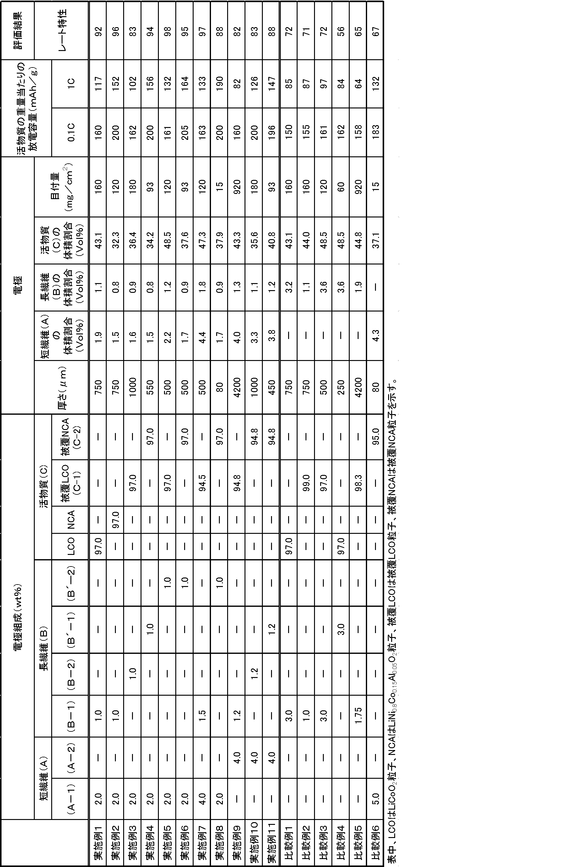
- Examples 2 to 11 and Comparative Examples 1 to 6> As shown in Table 1, a positive electrode for a lithium ion battery was prepared by changing the types, volume ratios, and electrode thicknesses and basis weights of short fibers (A), long fibers (B) and active materials (C). did.
- LCO represents LiCoO 2 particles
- NCA represents LiNi 0.8 Co 0.15 Al 0.05 O 2 particles
- coated LCO represents coated LCO particles
- coated NCA represents coated NCA particles.
- Example 12 Production of negative electrode> 2 parts by weight of short fibers (A-1), 4.2 parts by weight of long fibers (B-1) and non-graphitizable carbon as negative electrode active material particles [Carbotron manufactured by Kureha Battery Materials Japan Co., Ltd. ( (Registered trademark) PS (F)] 93.8 parts by weight was mixed with the above electrolyte solution to prepare an electrolyte slurry.
- Examples 13 to 22 and Comparative Examples 7 to 11> As shown in Table 2, a negative electrode for a lithium ion battery was prepared by changing the type, volume ratio, and thickness and basis weight of the short fiber (A), long fiber (B) and active material (C). did.
- HC represents non-graphitizable carbon particles
- coated HC represents coated non-graphitizable carbon particles.
- the evaluation batteries 1 to 22 and comparative batteries 1 to 11 were evaluated by the following method using a charge / discharge measuring device “Battery Analyzer 1470 type” (manufactured by Toyo Technica Co., Ltd.) at room temperature. Evaluation of the positive electrode was obtained by charging to 4.2 V with a current of 0.1 C and 1.0 C, respectively, and after discharging for 10 minutes, discharging to 2.7 V with a current of 0.1 C and 1.0 C, respectively. From the capacity, the rate characteristic was calculated by the following formula.
- the evaluation of the negative electrode was performed by charging the battery to a voltage of 1.5 V at a current of 0.1 C and 1.0 C, and after discharging for 10 minutes, discharging the battery to 10 mV at a current of 0.1 C and 1.0 C, respectively. From this, the rate characteristic (the ratio of the battery capacity at 0.1 C to the battery capacity at 1.0 C) was calculated by the following formula. A larger value of the rate characteristic means that there is less battery capacity reduction and excellent battery characteristics. Since the rate characteristic also depends on the electrode thickness, in this evaluation, the ratio of the battery capacity at 0.1 C and the battery capacity at 1.0 C is corrected so that comparison can be made even with electrodes having different thicknesses.
- the lithium ion battery electrode according to each example even when the electrode thickness is increased, the lithium ion battery electrode is excellent in electronic conductivity, although the electrode thickness is large. Thus, it was found that the discharge capacity per weight of the active material was high. It can be used as an electrode for a lithium ion battery having an excellent discharge capacity per unit area.
- the electrode for a lithium ion battery obtained by the present invention is particularly useful as an electrode for a bipolar secondary battery and a lithium ion secondary battery used for a mobile phone, a personal computer and a hybrid vehicle, and an electric vehicle.
- Lithium ion battery 10 210 Electrode for lithium ion battery (positive electrode) DESCRIPTION OF SYMBOLS 11, 211 First main surface 12, 212 of positive electrode Second main surface 13A of positive electrode Short fiber 13B Long fiber 14 Positive electrode active material particles 15, 25 Coating agent 16, 26 Conductive aid 20, 220 Electrode for lithium ion battery (negative electrode ) 21, 221 Negative electrode first main surface 22, 222 Negative electrode second main surface 24 Negative electrode active material particles 30 Separator 40, 50 Current collector 225 Slurry layer 470 Filter paper
Abstract
Description
しかしながら、双極型電極において電極の厚さを厚くすると、集電体からの距離が遠い活物質の割合が増加する。ここで、活物質自体の電子伝導性は高くないため、集電体からの距離が遠い活物質から集電体までの電子の移動はスムーズに行われないと考えられる。そのため、電極の厚さを単に厚くしただけでは活物質の量が増えたとしても電子伝導性が悪く、全活物質中の充放電に関与する有効活物質割合が低くなってしまう。また、電極の厚さを厚くした場合、電極空隙内のイオン拡散抵抗が大きく、大電流における充放電容量すなわちレート特性が大きく低下してしまうという問題が生じてしまう。
(1)まず、長繊維を用いると、活物質間の空隙の形状がより直線的となって、この空隙を通過するリチウムイオンの拡散経路長が短くなると考えられる。そのため、イオン拡散抵抗が小さくなる。
(2)短繊維も併用すると、長繊維のみでは接触できていなかった「活物質-活物質間」および「活物質-長繊維間」についても、より多くの導電パスが形成できる。そのため、電子抵抗が小さくなる。
(1)および(2)の結果、イオン拡散抵抗と電子抵抗の両方が小さくなる。そのため、大電流における充放電時にも多くの電気を取り出すことができ、レート特性が向上する。
本発明のリチウムイオン電池用電極は、リチウムイオン電池のセパレータ側に配置される第1主面と、集電体側に配置される第2主面とを備えたリチウムイオン電池用電極であって、
上記電極の厚さは50~5000μmであり、
上記第1主面と上記第2主面の間に、平均繊維長が50nm以上100μm未満である短繊維(A)、平均繊維長が100μm以上1000μm以下である長繊維(B)及び活物質粒子(C)を含み、
上記短繊維(A)及び上記長繊維(B)は導電性繊維であることを特徴とする。
短繊維(A)及び長繊維(B)は導電性繊維である。
図1に示すリチウムイオン電池1は、正極10と負極20を備えており、正極10と負極20の間にはセパレータ30が設けられている。
正極10のセパレータ30と反対の面には集電体40が、負極20のセパレータ30と反対の面には集電体50が設けられている。上記構造をまとめると、集電体40-正極10-セパレータ30-負極20-集電体50の順に積層構造が形成され、全体としてリチウムイオン電池1となっている。
正極10は所定の厚さt1を有するシート状の電極であり、セパレータ30側に配置される第1主面11及び集電体40側に配置される第2主面12を備えている。正極10には正極活物質粒子14が含まれている。
同様に、負極20も所定の厚さt2を有するシート状の電極であり、セパレータ30側に配置される第1主面21及び集電体50側に配置される第2主面22を備えている。負極20には負極活物質粒子24が含まれている。
正極10の厚さt1及び負極20の厚さt2は、それぞれ50~5000μmであり、このように電極が厚いと、電池内に多くの活物質を含ませることができ、リチウムイオン電池を高容量化することができる。
本発明のリチウムイオン電池用正極の厚さt1は好ましくは150~1500μmであり、より好ましくは200~950μmであり、さらに好ましくは250~900μmである。
本発明のリチウムイオン電池用負極の厚さt2は好ましくは150~1500μmであり、より好ましくは200~950μmであり、さらに好ましくは250~900μmである。
このような、本発明のリチウムイオン電池用電極を負極及び/又は正極に用いたリチウムイオン電池は本発明のリチウムイオン電池である。
図2は、図1に示すリチウムイオン電池の正極のみを模式的に示す断面図である。
正極10は、上述したように第1主面11と第2主面12を備えている。そして、第1主面11と第2主面12の間には、導電性繊維である短繊維(A)及び長繊維(B)が含まれている。図2では短繊維(A)を参照符号13A、長繊維(B)を参照符号13Bで示している。
第1主面11と第2主面12の間には、さらに活物質粒子(C)としての正極活物質粒子14が含まれている。
本発明のリチウムイオン電池用電極では、短繊維(A)と長繊維(B)の少なくとも一部が、第1主面から第2主面までを電気的に接続する導電通路を形成しており、導電通路は、導電通路の周囲の活物質粒子(C)と接していることが好ましい。
図2には、短繊維13A及び長繊維13Bの少なくとも一部が、第1主面11から第2主面12までを電気的に接続する導電通路を形成している様子を模式的に示している。
図2には、電極の厚さよりもその長さが短い長繊維13B及び短繊維13Aが複数本重なり合って導電通路を形成している様子を示している。
そして、導電通路の一方の末端に位置する短繊維13A又は長繊維13Bは第1主面11に達しており、導電通路の他方の末端に位置する短繊維13A又は長繊維13Bは第2主面12に達している。
また、1本の長繊維13Bが導電通路の一方の末端と他方の末端をつないでいてもよい。
また、図2には短繊維13A及び長繊維13Bにより形成される導電通路が周囲の正極活物質粒子14と接している様子も示している。
このような場合に、本発明のリチウムイオン電池用電極には短繊維(A)と長繊維(B)が含まれていると判断することができる。
導電性繊維の繊維長は、SEM観察により測定することができる。
まず、0.2mm角視野中に存在する繊維についてそれぞれ繊維長を測定し、50nm以上100μm未満の繊維につき、繊維長が横軸であり測定結果(繊維の本数)が縦軸であるヒストグラムを作成して繊維長分布をヒストグラム化する。
なお、繊維長の測定は三視野について行い、ヒストグラムは三視野の合計で作成する。
また、2mm角視野中に存在する繊維についてそれぞれ繊維長の測定を三視野について行い、100μm以上1000μm以下の繊維につき、50nm以上100μm未満の繊維と同様に繊維長分布をヒストグラム化する。
なお、0.2mm視野角での測定結果と2mm視野角での測定結果を合わせて繊維長分布を1つのヒストグラムとして記載しても良く、1つのヒストグラムで記載する場合は、測定結果(繊維の本数)のスケールが合うように換算すればよい。
なお、視野から一端がはみ出しており、繊維長が特定できない長い繊維についてはカウントしない。
そして、50nm以上100μm未満の領域に存在するピークのうち最も頻度の大きい繊維長(モード長)を短繊維(A)の平均繊維長とし、100μm以上1000μm以下の領域に存在する最も頻度の大きい繊維長(モード長)を長繊維(B)の平均繊維長とする。
なお、ヒストグラム作成時の横軸である繊維長は以下の間隔で記載し、測定結果もこの間隔となるようにまとめる。
50nm~500nm:50nm刻み
500nm~1μm:100nm刻み
1μm~100μm:10μm刻み
100μm~500μm:50μm刻み
500μm~1000μm:100μm刻み
短繊維(A)の電気伝導度が50mS/cm以上であると、短繊維(A)により第1主面から第2主面までを電気的に接続する導電通路を形成させた際の抵抗が小さく、集電体からの距離が遠い活物質からの電子の移動がよりスムーズに行われるため好ましい。
短繊維(A)の繊維径は、SEM観察し測定する。短繊維(A)の平均繊維径は0.2mm角視野中に存在する、繊維長が50nm以上100μm未満の繊維10本についてそれぞれ中央付近の直径を測定し、この測定を三視野について行い、合計30本の繊維の径の平均値をもって測定値とする。
長繊維(B)の電気伝導度が50mS/cm以上であると、長繊維(B)により第1主面から第2主面までを電気的に接続する導電通路を形成させた際の抵抗が小さく、集電体からの距離が遠い活物質からの電子の移動がよりスムーズに行われるため好ましい。
長繊維(B)の繊維径は、SEM観察し測定する。長繊維(B)の平均繊維径は2mm角視野中に存在する繊維長が100μm以上1000μm以下の繊維10本についてそれぞれ中央付近の直径を測定し、この測定を三視野について行い、合計30本の繊維の径の平均値をもって測定値とする。
電極の体積を基準として、短繊維(A)の占める体積の割合は、以下の式より導かれる。
[電極の体積を基準として、短繊維(A)の占める体積の割合][%]=
[(電極の単位面積あたりに使用した短繊維(A)の重量)/(短繊維(A)の比重)]/[(電極の単位面積)×(電極厚さ)]×100
なお、短繊維(A)の占める体積の割合を求める際には、繊維長が50nm以上100μm未満の繊維を短繊維(A)とする。
また、電極の体積を基準として、長繊維(B)の占める体積の割合は、以下の式より導かれる。
[電極の体積を基準として、長繊維(B)の占める体積の割合][%]=
[(電極の単位面積あたりに使用した長繊維(B)の重量)/(長繊維(B)の比重)]/[(電極の単位面積)×(電極厚さ)]×100
なお、長繊維(B)の占める体積の割合を求める際には、繊維長が100μm以上1000μm以下の繊維を長繊維(B)とする。
短繊維(A)の占める体積の割合及び長繊維(B)の占める体積の割合が少ないということは、短繊維(A)及び長繊維(B)が占有していない空隙に活物質粒子(C)が充填されることを意味しており、活物質粒子(C)が充填されることによって、高容量のリチウムイオン電池用電極となる。
また、本発明のリチウムイオン電池用電極においては、短繊維(A)の占める体積(VA)及び長繊維(B)の占める体積(VB)の合計(VA+VB)と活物質粒子(C)の占める体積(VC)との比率[(VA+VB)/VC]が0.00125~0.5であることが好ましく、0.02~0.3であることがより好ましい。
短繊維(A)の占める体積(VA)及び長繊維(B)の占める体積(VB)が少なく大部分が活物質粒子(C)であることによって、高容量のリチウムイオン電池用電極となる。
なお、短繊維(A)の占める体積(VA)、長繊維(B)の占める体積(VB)及び活物質粒子(C)の占める体積(VC)は、以下の方法により測定する。
電解液等を乾燥させ短繊維(A)、長繊維(B)及び活物質粒子(C)が混合した電極1cm2当たりの重量[w(g)]並びに電極の膜厚[t(cm)]を測定し、短繊維(A)の真比重[dA(g/cm3)]、長繊維(B)の真比重[dB(g/cm3)]、活物質粒子(C)の真比重[dC(g/cm3)]並びに短繊維(A)、長繊維(B)及び活物質粒子(C)の本発明の電極を構成する材料の合計重量に対する仕込み割合(WA、WB、WC)から算出する。
VA=(w×WA/dA)/(t×1)×100
VB=(w×WB/dB)/(t×1)×100
VC=(w×WC/dC)/(t×1)×100
なお、LiNi0.8Co0.15Al0.05O2等のリチウムニッケル複合酸化物とは、下記一般式(1)で示されるような複合酸化物であり、
一般式(1):LiX(Ni1-yCoy)1-zMzO2(但し、式中、x、y、zは、0.98≦x≦1.10、0.05≦y≦0.4、0.01≦z≦0.2であり、Mは、Al、Mg、Mn、Ti、Fe、Cu、Zn、およびGaからなる群より選択される少なくとも1種の金属元素である)で表される化合物である。
その好ましい例として、リチウム-ニッケル-マンガン-コバルト複合酸化物、またはリチウム-ニッケル-コバルト-アルミニウム複合酸化物などが挙げられる。
図2に示す形態では、正極活物質粒子14の周囲が被覆剤15で被覆されている。被覆剤は被覆用樹脂を含んでおり、正極活物質粒子の周囲が被覆剤で被覆されていると、電極の体積変化が緩和され、電極の膨脹を抑制することができる。被覆用樹脂の例としては、ビニル樹脂、ウレタン樹脂、ポリエステル樹脂、ポリアミド樹脂、エポキシ樹脂、ポリイミド樹脂、シリコーン樹脂、フェノール樹脂、メラミン樹脂、ユリア樹脂、アニリン樹脂、アイオノマー樹脂、ポリカーボネート等が挙げられる。これらの中ではビニル樹脂、ウレタン樹脂、ポリエステル樹脂又はポリアミド樹脂が好ましい。
本発明のリチウムイオン電池用電極において、活物質粒子(C)として被覆活物質粒子を用いる場合、リチウムイオン電池用電極は結着剤(バインダともいう)を含まないことが好ましい。ここでいう結着剤としては、リチウムイオン電池の電極において活物質粒子と集電体との結着及び活物質粒子同士の結着を目的として用いられる公知の結着剤(デンプン、ポリフッ化ビニリデン、ポリビニルアルコール、カルボキシメチルセルロース、ポリビニルピロリドン、テトラフルオロエチレン、スチレン-ブタジエンゴム、ポリエチレン及びポリプロピレン等の高分子化合物)等が挙げられる。
被覆活物質粒子ではない活物質粒子を用いるリチウムイオン電池用電極においては、結着剤で活物質粒子を電極内に固定することで導電経路を維持する必要がある。しかし、被覆活物質粒子を用いる場合は、被覆用樹脂の働きによって活物質粒子を電極内に固定することなく導電経路を維持することができるため、結着剤を添加する必要がない。結着剤を添加しないことによって、活物質粒子が電極内に固定化されないため活物質粒子の体積変化に対する緩和能力が良好となる。
なお、活物質粒子が被覆活物質粒子である場合、被覆剤と導電通路が接している場合も、導電通路が活物質粒子と接しているとみなすことができる。
導電助剤としては、導電性を有する材料から選択される。
具体的には、金属[アルミニウム、ステンレス(SUS)、銀、金、銅及びチタン等]、カーボン[グラファイト及びカーボンブラック(アセチレンブラック、ケッチェンブラック、ファーネスブラック、チャンネルブラック、サーマルランプブラック等)等]、及びこれらの混合物等が挙げられるが、これらに限定されるわけではない。
これらの導電助剤は1種単独で用いられてもよいし、2種以上併用してもよい。また、これらの合金又は金属酸化物が用いられてもよい。電気的安定性の観点から、好ましくはアルミニウム、ステンレス、カーボン、銀、金、銅、チタン及びこれらの混合物であり、より好ましくは銀、金、アルミニウム、ステンレス及びカーボンであり、さらに好ましくはカーボンである。またこれらの導電助剤とは、粒子系セラミック材料や樹脂材料の周りに導電性材料(上記した導電助剤の材料のうち金属のもの)をめっき等でコーティングしたものでもよい。
また、導電助剤16は、被覆剤15の中に含まれていてもよく、導電助剤16が正極活物質粒子14と接していてもよい。導電助剤が被覆剤の中に含まれていたり、正極活物質粒子と接していたりすると、正極活物質粒子から導電通路に達するまでの電子伝導性をさらに高めることができる。
負極活物質粒子としては、黒鉛、難黒鉛化性炭素、アモルファス炭素、高分子化合物焼成体(例えばフェノール樹脂及びフラン樹脂等を焼成し炭素化したもの等)、コークス類(例えばピッチコークス、ニードルコークス及び石油コークス等)、炭素繊維、導電性高分子(例えばポリアセチレン及びポリピロール等)、スズ、シリコン、及び金属合金(例えばリチウム-スズ合金、リチウム-シリコン合金、リチウム-アルミニウム合金及びリチウム-アルミニウム-マンガン合金等)、リチウムと遷移金属との複合酸化物(例えばLi4Ti5O12等)等が挙げられる。
負極においても、導電通路が導電通路の周囲の負極活物質粒子と接しているので、正極の場合と同様に、負極活物質粒子から発生した電子がすぐに導電通路に達し、導電通路を流れてスムーズに集電体にまで達する。また、集電体から負極活物質粒子に向かって流れる電子もスムーズに負極活物質にまで達することができる。
また、本発明のリチウムイオン電池用電極が負極である場合においても、活物質粒子(C)として被覆活物質粒子を用いる場合、リチウムイオン電池用電極は結着剤を含まないことが好ましい。その理由はリチウムイオン電池用電極が正極である場合と同様である。
本発明のリチウムイオン電池用電極の製造方法の一の態様は、本発明のリチウムイオン電池用電極の製造方法であって、上記短繊維(A)、上記長繊維(B)及び上記活物質粒子(C)を含むスラリー(Y)を、膜(E)上に塗布する工程(Q1)と、加圧又は減圧して、上記活物質粒子(C)、上記短繊維(A)及び上記長繊維(B)を上記膜(E)上に定着する工程(Q2)とを含むことを特徴とする。
スラリー(Y)としては、活物質を含むスラリー(X)にさらに短繊維(A)及び長繊維(B)を加えてスラリー中に短繊維(A)及び長繊維(B)を分散させたものが挙げられる。
活物質粒子(C)を含むスラリー(X)は、溶剤(F)を含む溶剤スラリー(X1)であるか、電解液(D)を含む電解液スラリー(X2)であることが好ましい。
溶剤(F)としては、水、1-メチル-2-ピロリドン(N-メチルピロリドン)、メチルエチルケトン、ジメチルホルムアミド、ジメチルアセトアミド、N,N-ジメチルアミノプロピルアミン及びテトラヒドロフラン等が挙げられる。
また、電解液(D)としては、リチウムイオン電池の製造に用いられる、電解質及び非水溶媒を含有する電解液を使用することができる。
電解質としては、通常の電解液に用いられているもの等が使用でき、例えば、LiPF6、LiBF4、LiSbF6、LiAsF6及びLiClO4等の無機酸のリチウム塩、LiN(CF3SO2)2、LiN(C2F5SO2)2及びLiC(CF3SO2)3等の有機酸のリチウム塩等が挙げられる。これらの内、電池出力及び充放電サイクル特性の観点から好ましいのはLiPF6である。
非水溶媒は1種を単独で用いてもよいし、2種以上を併用してもよい。
導電助剤としては本発明のリチウムイオン電池用電極の説明で説明したものを用いることができる。
結着剤としてはデンプン、ポリフッ化ビニリデン、ポリビニルアルコール、カルボキシメチルセルロース、ポリビニルピロリドン、テトラフルオロエチレン、スチレン-ブタジエンゴム、ポリエチレン及びポリプロピレン等の高分子化合物が挙げられる。
なお、活物質粒子(C)として被覆活物質粒子を用いる場合、スラリー(X)には、結着剤は添加しないことが好ましい。被覆活物質粒子ではない活物質粒子を用いるリチウムイオン電池用電極においては、結着剤で活物質粒子を電極内に固定することで導電経路を維持する必要がある。しかし、被覆活物質粒子を用いる場合には被覆用樹脂の働きによって活物質粒子を電極内に固定することなく導電経路を維持することができるため、結着剤を添加する必要がない。結着剤を添加しないことによって、活物質粒子が電極内に固定化されないため活物質粒子の体積変化に対する緩和能力が良好となる。
また、スラリー(Y)は溶剤(F)を含む溶剤スラリーであってもよい。
このような特性を有する材料の例としては、炭素繊維等の導電性繊維を配合した濾紙、金属メッシュ等が挙げられる。
金属メッシュとしては、ステンレス製メッシュを用いることが好ましく、例えばSUS316製の綾畳織金網(サンネット工業製)等が挙げられる。金属メッシュの目開きは、活物質粒子及び導電部材が通過しない程度とすることが好ましく、例えば2300メッシュのものを用いることが好ましい。
図3(a)には膜上にスラリーを塗布した様子を模式的に示しており、膜としての濾紙470上に、正極活物質粒子14と短繊維13A及び長繊維13Bを含むスラリーが塗布されている。
加圧操作の方法としては、スラリーの塗布面の上からプレス機を用いてプレスする方法が挙げられる。また、減圧操作の方法としては、構造体にスラリーが塗布されていない側の面に濾紙やメッシュ等を当てて、真空ポンプにより吸引する方法が挙げられる。
加圧又は減圧によりスラリー(Y)から電解液又は溶剤が除去されて、短繊維(A)及び長繊維(B)と活物質粒子(C)が膜(E)の上に定着されて、流動しない程度に緩くその形状が維持された状態となる。
図3(b)には、短繊維13A及び長繊維13Bと正極活物質粒子14が濾紙470上で定着されてなる電極210を示している。
電極210において膜(E)が導電性材料からなるとき、膜(E)は集電体として使用することができ、また、集電体と膜(E)を接触させて一つの集電体として機能させることもできる。すなわち、電極210において第2主面212は短繊維13A及び/又は長繊維13Bが濾紙470と接触する部分として定めることができる。
膜(E)が導電性を有さない材料であるときは、膜(E)をセパレータ側に配置するようにするとよい。また、膜(E)をセパレータとしてもよい。導電性を有さない材料からなる膜の例としては、アラミドセパレータ(日本バイリーン株式会社製)等が挙げられる。
プレス工程(Q3)は、工程(Q2)における加圧又は減圧よりも、さらに圧力差を大きくして活物質粒子(C)の密度を向上させる工程である。プレス工程(Q3)は、工程(Q2)が減圧である場合に加圧を加えるという態様と、工程(Q2)が加圧である場合に加圧する圧力をさらに高くするという態様の両方を含む概念である。
集電体としては、アルミ、銅、アルミニウム、チタン、ステンレス鋼、ニッケル、焼成炭素、導電性高分子及び導電性ガラス等が挙げられる。
スラリー(Y)としては、図3(a)を用いて説明したスラリー(Y)と同様のスラリーを用いることができ、スラリー(X)にさらに短繊維(A)及び長繊維(B)を加えてスラリー中に短繊維(A)及び長繊維(B)を分散させたものが挙げられる。
スラリー(Y)は、電解液(D)を含む電解液スラリー(Y1)であることが好ましい。電解液(D)としては上述した電解液スラリー(X2)における電解液(D)と同様のものを用いることができる。また、スラリー(Y)は溶剤(F)を含む溶剤スラリーであってもよい。
図4(a)には集電体50上にスラリーを塗布してスラリー層225を形成した様子を模式的に示しており、集電体50上に、負極活物質粒子24と短繊維13A及び長繊維13Bを含むスラリーが塗布されており、スラリー層225が形成されている。
図4(a)に示す形態では、負極活物質粒子24の周囲が被覆剤25で被覆されており、スラリーには導電助剤26が含まれている。
短繊維13A、長繊維13B、被覆剤25及び導電助剤26については本発明のリチウムイオン電池用電極(正極)の説明でその詳細を説明した短繊維13A、長繊維13B、被覆剤15、導電錠剤16とそれぞれ同様である。
また、負極活物質粒子24も、本発明のリチウムイオン電池用電極の説明でその詳細を説明した負極活物質粒子と同様である。
セパレータとしては、アラミドセパレータ(日本バイリーン株式会社製)、ポリエチレン、ポリプロピレン製フィルムの微多孔膜、多孔性のポリエチレンフィルムとポリプロピレンとの多層フィルム、ポリエステル繊維、アラミド繊維、ガラス繊維等からなる不織布、及びそれらの表面にシリカ、アルミナ、チタニア等のセラミック微粒子を付着させたもの等が挙げられる。
吸液性材料としては、タオル等の吸液性布、紙、吸液性樹脂等を使用することができる。
吸液によりスラリー(Y)から電解液又は溶剤が除去されて、短繊維(A)及び長繊維(B)と活物質粒子(C)が集電体とセパレータの間に定着されて、流動しない程度に緩くその形状が維持された状態となる。
加圧の方法は特に限定されないが、種々の方法で実施できる。たとえば、公知のプレス機を用いる方法及び重量物等を重りとして載置して加圧する方法が挙げられ、加圧は超音波振動機等で加振しながら行っても良い。セパレータの上面側又は下面側から加圧する場合の圧力は、0.8~41kg/cm2が好ましく、0.9~10kg/cm2がより好ましい。圧力がこの範囲にあると電極内部の導電通路を良好に形成することができるので電池をより高容量化でき好ましい。
電極220においては、電極の第1主面221がセパレータ30と接しており、電極の第2主面222が集電体50と接している。
このようなリチウムイオン電池用電極の製造方法であると、電極がセパレータと集電体で挟まれた状態で製造される。そのため、電極の両側にセパレータと集電体を配置する工程を別途行う必要がなく、双極型電極として好ましい形態の電極が少ない工程で得られるため好ましい。
また、集電体の一方の面に正極を形成し、もう一方の面に負極を形成して双極型電極を作製し、双極型電極をセパレータと積層してセル容器に収納し、電解液を注入し、セル容器を密封することでも得られる。
また、正極、負極のいずれか一方に本発明のリチウムイオン電池用電極を用いてもよく、正極、負極を共に本発明のリチウムイオン電池用電極としてリチウムイオン電池としてもよい。
撹拌機、温度計、還流冷却管、滴下ロート及び窒素ガス導入管を付した4つ口フラスコに、酢酸エチル83部とメタノール17部とを仕込み68℃に昇温した。次いで、メタクリル酸242.8部、メチルメタクリレート97.1部、2-エチルヘキシルメタクリレート242.8部、酢酸エチル52.1部及びメタノール10.7部を配合したモノマー配合液と、2,2’-アゾビス(2,4-ジメチルバレロニトリル)0.263部を酢酸エチル34.2部に溶解した開始剤溶液とを4つ口フラスコ内に窒素を吹き込みながら、撹拌下、滴下ロートで4時間かけて連続的に滴下してラジカル重合を行った。滴下終了後、2,2’-アゾビス(2,4-ジメチルバレロニトリル)0.583部を酢酸エチル26部に溶解した開始剤溶液を滴下ロートを用いて2時間かけて連続的に追加した。さらに、沸点で重合を4時間継続した。溶媒を除去し、樹脂582部を得た後、イソプロパノールを1,360部加えて、樹脂濃度30重量%のビニル樹脂からなる被覆用樹脂溶液を得た。
LiCoO2粉末[日本化学工業(株)製 セルシードC-8G]96重量部を万能混合機に入れ、室温、150rpmで撹拌した状態で、被覆用樹脂溶液(樹脂固形分濃度30重量%)を樹脂固形分として2重量部になるように60分かけて滴下混合し、さらに30分撹拌した。
次いで、撹拌した状態でアセチレンブラック[電気化学工業(株)製 デンカブラック(登録商標)]2重量部を3回に分けて混合し、30分撹拌したままで70℃に昇温し、100mmHgまで減圧し30分保持した。上記操作により被覆正極活物質粒子(C-1)を得た。
LiCoO2粉末[日本化学工業(株)製 セルシードC-8G]96重量部を、LiNi0.8Co0.15Al0.05O2粉末(以下、NCAとも記載する)粉末に変更する以外は、(C-1)の作製方法と同様の操作をして、被覆正極活物質粒子(C-2)を得た。
難黒鉛化性炭素[(株)クレハ・バッテリー・マテリアルズ・ジャパン製 カーボトロン(登録商標)PS(F)]90重量部を万能混合機に入れ、室温、150rpmで撹拌した状態で、被覆用樹脂溶液(樹脂固形分濃度30重量%)を樹脂固形分として5重量部になるように60分かけて滴下混合し、さらに30分撹拌した。
次いで、撹拌した状態でアセチレンブラック[電気化学工業(株)製 デンカブラック(登録商標)]5重量部を3回に分けて混合し、30分撹拌したままで70℃に昇温し、0.01MPaまで減圧し30分保持した。上記操作により被覆負極活物質粒子(C-3)を得た。
短繊維(A-1)は、Eiichi Yasuda,Asao Oya,Shinya Komura,Shigeki Tomonoh,Takashi Nishizawa,Shinsuke Nagata,Takashi Akatsu、CARBON、50、2012、1432-1434及びEiichi Yasuda,Takashi Akatsu,Yasuhiro Tanabe,Kazumasa Nakamura,Yasuto Hoshikawa,Naoya Miyajima、TANSO、255、2012、254~265頁の製造方法を参考にして製造した。
炭素前駆体として合成メソフェーズピッチAR・MPH[三菱ガス化学(株)製]10重量部とポリメチルペンテンTPX RT18[三井化学(株)製]90重量部を、バレル温度310℃、窒素雰囲気下で一軸押出機を用いて溶融混練し、樹脂組成物を調製した。
上記樹脂組成物を390℃で溶融押出し紡糸した。紡糸した樹脂組成物を電気炉に入れ、窒素雰囲気下270℃で3時間保持し炭素前駆体を安定化させた。ついで、電気炉を1時間かけて500℃まで昇温し、500℃で1時間保持し、ポリメチルペンテンを分解除去した。電気炉を2時間かけて1000℃まで昇温し1000℃で30分間保持し、残った安定化させた炭素前駆体を導電性繊維とした。
得られた導電性繊維90重量部、水500重量部とΦ0.1mmのジルコニアボール1000重量部をポットミル容器に入れ5分間粉砕した。ジルコニアボールを分級後、100℃で乾燥し、短繊維(A-1)を得た。
SEMでの測定結果より、平均繊維径は、0.3μm、平均繊維長は、26μmであった。また、短繊維(A-1)の電気伝導度は600mS/cmであった。
上記短繊維(A-1)の作製において、溶融押出し紡糸の条件を変更した以外は同様にして、導電性の短繊維(A-2)を得た。
SEMでの測定結果より、平均繊維径は、0.2μm、平均繊維長は、9μmであった。
また、短繊維(A-2)の電気伝導度は600mS/cmであった。
長繊維として炭素質炭素繊維[大阪ガスケミカル(株)製 ドナカーボ・ミルド S-243:平均繊維長500μm、平均繊維径13μm:電気伝導度200mS/cm]を準備した。
長繊維として炭素質炭素繊維[大阪ガスケミカル(株)製 ドナカーボ・ミルド S-344:平均繊維長960μm、平均繊維径18μm:電気伝導度200mS/cm]を準備した。
長繊維として黒鉛質炭素繊維[大阪ガスケミカル(株)製 ドナカーボ・ミルド SG-249:平均繊維長110μm、平均繊維径13μm:電気伝導度600mS/cm]を準備した。
長繊維として黒鉛質炭素繊維[日本グラファイトファイバー(株)製XN-100-15M:平均繊維長150μm、平均繊維径10μm:電気伝導度600mS/cm]を準備した。
エチレンカーボネート(EC)とジエチルカーボネート(DEC)の混合溶媒(体積比率1:1)に、LiPF6を1mol/Lの割合で溶解させてリチウムイオン電池用電解液を作製した。
短繊維(A-1)2重量部、長繊維(B-1)1重量部及び正極活物質粒子としてのLiCoO2粉末[日本化学工業(株)製 セルシードC-8G]97重量部を上記電解液と混合して、電解液スラリーを作製した。
膜(E)としてステンレス製メッシュ[サンネット工業(株)製 SUS316綾畳織2300メッシュ]を準備し、上記ステンレス製メッシュに電解液スラリーを塗布し、吸引濾過(減圧)することにより、正極活物質粒子と短繊維及び長繊維をステンレス製メッシュ上に定着させてリチウムイオン電池用正極を作製した。
表1に示すように、短繊維(A)、長繊維(B)及び活物質(C)の種類、体積割合、並びに、電極の厚さ及び目付量を変更してリチウムイオン電池用正極を作製した。
表1中、LCOはLiCoO2粒子、NCAはLiNi0.8Co0.15Al0.05O2粒子、被覆LCOは被覆LCO粒子、被覆NCAは被覆NCA粒子を示す。
短繊維(A-1)2重量部、長繊維(B-1)4.2重量部及び負極活物質粒子としての難黒鉛化性炭素[(株)クレハ・バッテリー・マテリアルズ・ジャパン製 カーボトロン(登録商標)PS(F)]93.8重量部を上記電解液と混合して、電解液スラリーを作製した。
膜(E)としてアラミドセパレータ(日本バイリーン株式会社製)を準備し、上記アラミドセパレータに電解液スラリーを塗布し、吸引濾過(減圧)するとともに加圧圧力1.5kg/cm2で加圧することにより、負極活物質粒子と炭素繊維をアラミドセパレータ上に定着させてリチウムイオン電池用負極を作製した。
表2に示すように、短繊維(A)、長繊維(B)及び活物質(C)の種類、体積割合、並びに、電極の厚さ及び目付量を変更してリチウムイオン電池用負極を作製した。
表2中、HCは難黒鉛化性炭素粒子、被覆HCは被覆難黒鉛化性炭素粒子を示す。

実施例1~11及び比較例1~6のいずれかで作製した正極を、17mmφに打ち抜き、17mmφのLi金属からなる負極と共に2032型コインセル内の両端に配置した。
正極側の集電体としては厚さ20μmのアルミニウム電解箔を用い、ステンレス製メッシュを集電体側に配置した。
電極間にセパレータ(セルガード3501)を2枚挿入し、リチウムイオン電池用セルを作製した。
セルに上記電解液を注液密封し、以下の方法で放電容量(mAh)を測定し、活物質の重量で除して活物質の重量当たりの放電容量(mAh/g)として評価した。
この評価で作製した電池を評価用電池1~11及び比較用電池1~6とした。
実施例12~22及び比較例7~11のいずれかで作製した負極を、17mmφに打ち抜き、17mmφのLi金属からなる正極と共に2032型コインセル内の両端に配置した。
負極側の集電体としては厚さ20μmの銅箔を用い、アラミドセパレータをセパレータ側(正極側)に配置した。
電極間にセパレータ(セルガード3501)を2枚挿入し、リチウムイオン電池用セルを作製した。セルに上記電解液を注液密封し、以下の方法で放電容量(mAh)を測定し、活物質の重量で除して活物質の重量当たりの放電容量(mAh/g)として評価した。
この評価で作製した電池を評価用電池12~22及び比較用電池7~11とした。
室温下、充放電測定装置「バッテリーアナライザー1470型」[東陽テクニカ(株)製]を用いて以下の方法により評価用電池1~22及び比較用電池1~11の評価を行った。
正極の評価は0.1C及び1.0Cの電流で4.2Vまでそれぞれ充電し、10分間の休止後、0.1C及び1.0Cの電流で2.7Vまでそれぞれ放電して得られた電池容量から、以下の式でレート特性を算出した。
負極の評価は0.1C及び1.0Cの電流で電圧1.5Vまでそれぞれ充電し、10分間の休止後、0.1C及び1.0Cの電流で10mVまでそれぞれ放電して得られた電池容量から、以下の式でレート特性(0.1Cでの電池容量と1.0Cでの電池容量の比率)を算出した。レート特性の値が大きいほど容量の低下が少なく優れた電池特性を有することを意味する。なお、レート特性は電極の厚さにも依存するため、本評価においては、異なる厚さの電極でも比較が出来るよう、0.1Cでの電池容量と1.0Cでの電池容量の比率に補正係数[0.5×(電極の厚さ(μm))1.4]をかけた値をレート特性とした。
(レート特性[%])=[1.0Cにおける充電(または放電)容量]÷[0.1Cにおける充電(または放電)容量]×100×0.5×(電極の厚さ(μm))1.4
10、210 リチウムイオン電池用電極(正極)
11、211 正極の第1主面
12、212 正極の第2主面
13A 短繊維
13B 長繊維
14 正極活物質粒子
15、25 被覆剤
16、26 導電助剤
20、220 リチウムイオン電池用電極(負極)
21、221 負極の第1主面
22、222 負極の第2主面
24 負極活物質粒子
30 セパレータ
40、50 集電体
225 スラリー層
470 濾紙
Claims (18)
- リチウムイオン電池のセパレータ側に配置される第1主面と、集電体側に配置される第2主面とを備えたリチウムイオン電池用電極であって、
前記電極の厚さは50~5000μmであり、
前記第1主面と前記第2主面の間に、平均繊維長が50nm以上100μm未満である短繊維(A)、平均繊維長が100μm以上1000μm以下である長繊維(B)及び活物質粒子(C)を含み、
前記短繊維(A)及び前記長繊維(B)は導電性繊維であることを特徴とするリチウムイオン電池用電極。 - 前記短繊維(A)は、前記第1主面と前記第2主面の間に離散して存在する導電性繊維であり、
前記短繊維(A)の電気伝導度は50mS/cm以上である請求項1に記載のリチウムイオン電池用電極。 - 前記短繊維(A)の平均繊維径が0.01~20μmである請求項1又は2に記載のリチウムイオン電池用電極。
- 前記長繊維(B)は、前記第1主面と前記第2主面の間に離散して存在する導電性繊維であり、
前記長繊維(B)の電気伝導度は50mS/cm以上である請求項1~3のいずれかに記載のリチウムイオン電池用電極。 - 前記長繊維(B)の平均繊維径が0.1~100μmである請求項1~4のいずれかに記載のリチウムイオン電池用電極。
- 前記電極の体積を基準として、前記短繊維(A)の占める体積の割合が0.1~15vol%、前記長繊維(B)の占める体積の割合が0.001~15vol%である請求項1~5のいずれかに記載のリチウムイオン電池用電極。
- 前記短繊維(A)の占める体積(VA)と前記長繊維(B)の占める体積(VB)との比率(VA/VB)が、0.2~50である請求項1~6のいずれかに記載のリチウムイオン電池用電極。
- 前記電極の体積を基準として、前記活物質粒子(C)の占める体積の割合が30~80vol%である請求項1~7のいずれかに記載のリチウムイオン電池用電極。
- 前記活物質粒子(C)が、表面の少なくとも一部が被覆用樹脂及び導電助剤を含む被覆剤で被覆されてなる被覆活物質粒子である請求項1~8のいずれかに記載のリチウムイオン電池用電極。
- 請求項1~9のいずれかに記載のリチウムイオン電池用電極を負極及び/又は正極に用いたリチウムイオン電池。
- 請求項1~9のいずれかに記載のリチウムイオン電池用電極の製造方法であって、
前記短繊維(A)、前記長繊維(B)及び前記活物質粒子(C)を含むスラリー(Y)を、膜(E)上に塗布する工程(Q1)と、
加圧又は減圧して、前記活物質粒子(C)、前記短繊維(A)及び前記長繊維(B)を前記膜(E)上に定着する工程(Q2)とを含むことを特徴とするリチウムイオン電池用電極の製造方法。 - 前記スラリー(Y)は、電解液(D)を含む電解液スラリー(Y1)であり、
前記膜(E)が前記活物質粒子(C)を透過させず前記電解液(D)を透過させる膜であり、
前記工程(Q2)において、加圧又は減圧して前記電解液(D)を前記膜(E)を透過させて除去する請求項11に記載のリチウムイオン電池用電極の製造方法。 - 前記工程(Q2)の後、スラリー(Y)をさらに強い圧力で加圧するプレス工程(Q3)を行う請求項11又は12に記載のリチウムイオン電池用電極の製造方法。
- 前記膜(E)の電気伝導度は100mS/cm以上である請求項11~13のいずれかに記載のリチウムイオン電池用電極の製造方法。
- 前記膜(E)上に定着された前記リチウムイオン電池用電極を、集電体又はセパレータの主面に転写する工程(Q4)を行って、リチウムイオン電池用電極の第1主面がセパレータの主面に配置されたリチウムイオン電池用電極を形成する、又は、リチウムイオン電池用電極の第2主面が集電体の主面に配置されたリチウムイオン電池用電極を形成する、請求項11~14のいずれかに記載のリチウムイオン電池用電極の製造方法。
- 請求項1~9のいずれかに記載のリチウムイオン電池用電極の製造方法であって、
前記短繊維(A)、前記長繊維(B)及び前記活物質粒子(C)を含むスラリー(Y)を、集電体上に塗布して集電体上にスラリー層を形成する工程(T1)と、
前記スラリー層の上にセパレータを載置して、セパレータの上面側から吸液して、前記活物質粒子(C)、前記短繊維(A)及び前記長繊維(B)を前記集電体と前記セパレータの間に定着する工程(T2)とを含むことを特徴とするリチウムイオン電池用電極の製造方法。 - 前記スラリー(Y)は、電解液(D)を含む電解液スラリー(Y1)である請求項16に記載のリチウムイオン電池用電極の製造方法。
- 前記セパレータの上面に吸液性材料を置いて前記セパレータの上面側からの吸液を行う請求項16又は17に記載のリチウムイオン電池用電極の製造方法。
Priority Applications (4)
| Application Number | Priority Date | Filing Date | Title |
|---|---|---|---|
| CN201680018564.5A CN107431185B (zh) | 2015-03-27 | 2016-03-03 | 锂离子电池用电极、锂离子电池以及锂离子电池用电极的制造方法 |
| US15/561,563 US10957908B2 (en) | 2015-03-27 | 2016-03-03 | Electrode for lithium ion battery, lithium ion battery, and method for producing electrode for lithium ion battery |
| EP16772071.3A EP3276707B1 (en) | 2015-03-27 | 2016-03-03 | Electrode for lithium-ion cell, lithium-ion cell, and method of manufacturing electrode for lithium-ion cell |
| KR1020177027169A KR20170120680A (ko) | 2015-03-27 | 2016-03-03 | 리튬 이온 전지용 전극, 리튬 이온 전지 및 리튬 이온 전지용 전극의 제조 방법 |
Applications Claiming Priority (2)
| Application Number | Priority Date | Filing Date | Title |
|---|---|---|---|
| JP2015066633 | 2015-03-27 | ||
| JP2015-066633 | 2015-03-27 |
Publications (1)
| Publication Number | Publication Date |
|---|---|
| WO2016158187A1 true WO2016158187A1 (ja) | 2016-10-06 |
Family
ID=57004467
Family Applications (1)
| Application Number | Title | Priority Date | Filing Date |
|---|---|---|---|
| PCT/JP2016/056568 WO2016158187A1 (ja) | 2015-03-27 | 2016-03-03 | リチウムイオン電池用電極、リチウムイオン電池及びリチウムイオン電池用電極の製造方法 |
Country Status (6)
| Country | Link |
|---|---|
| US (1) | US10957908B2 (ja) |
| EP (1) | EP3276707B1 (ja) |
| JP (1) | JP6716288B2 (ja) |
| KR (1) | KR20170120680A (ja) |
| CN (1) | CN107431185B (ja) |
| WO (1) | WO2016158187A1 (ja) |
Cited By (8)
| Publication number | Priority date | Publication date | Assignee | Title |
|---|---|---|---|---|
| WO2017219235A1 (en) * | 2016-06-21 | 2017-12-28 | GM Global Technology Operations LLC | Lithium-ion battery with wire-containing electrodes |
| JP2018067532A (ja) * | 2016-10-14 | 2018-04-26 | 三洋化成工業株式会社 | リチウムイオン電池用正極及びリチウムイオン電池 |
| WO2018117088A1 (ja) * | 2016-12-20 | 2018-06-28 | 日産自動車株式会社 | リチウムイオン電池用負極 |
| WO2018117087A1 (ja) * | 2016-12-20 | 2018-06-28 | 日産自動車株式会社 | リチウムイオン電池用負極及びリチウムイオン電池 |
| JP2018101625A (ja) * | 2016-12-20 | 2018-06-28 | 三洋化成工業株式会社 | リチウムイオン電池用負極 |
| JP2018133237A (ja) * | 2017-02-16 | 2018-08-23 | 三洋化成工業株式会社 | リチウムイオン電池 |
| JP2018152340A (ja) * | 2017-03-13 | 2018-09-27 | 三洋化成工業株式会社 | リチウムイオン電池用電極及びリチウムイオン電池用電極の製造方法 |
| JP2018200804A (ja) * | 2017-05-26 | 2018-12-20 | 戸田工業株式会社 | リチウムイオン二次電池用電極、及びその製造方法 |
Families Citing this family (13)
| Publication number | Priority date | Publication date | Assignee | Title |
|---|---|---|---|---|
| JP6209706B2 (ja) * | 2015-10-20 | 2017-10-04 | 蓮尾 俊治 | 蓄電デバイスの集電体用のアルミニウム不織繊維材、その製造方法、前記アルミニウム不織繊維材を用いた電極、およびその製造方法 |
| EP3557661B1 (en) * | 2016-12-15 | 2021-02-03 | Nissan Motor Co., Ltd. | Secondary battery electrode, and secondary battery |
| JP6670231B2 (ja) * | 2016-12-22 | 2020-03-18 | I&Tニューマテリアルズ株式会社 | 蓄電デバイスの電極、蓄電デバイスの電極用のスラリーおよびその製造方法 |
| WO2019009239A1 (ja) * | 2017-07-03 | 2019-01-10 | 株式会社村田製作所 | 二次電池、電池パック、電動車両、電力貯蔵システム、電動工具および電子機器 |
| JP6927012B2 (ja) * | 2017-12-15 | 2021-08-25 | トヨタ自動車株式会社 | 蓄電デバイス用電極の製造方法、蓄電デバイス用電極および蓄電デバイス |
| JP2021526710A (ja) * | 2018-05-24 | 2021-10-07 | 24エム・テクノロジーズ・インコーポレイテッド24M Technologies, Inc. | 高エネルギー密度の組成勾配電極およびその製造方法 |
| WO2020105729A1 (ja) * | 2018-11-22 | 2020-05-28 | 国立大学法人信州大学 | リチウムイオン二次電池用正極、リチウムイオン二次電池およびリチウムイオン二次電池用正極の製造方法 |
| JP7097283B2 (ja) * | 2018-11-30 | 2022-07-07 | 日産自動車株式会社 | 電池用電極の製造方法および電池用電極の製造装置 |
| JP6894947B2 (ja) * | 2019-07-31 | 2021-06-30 | I&Tニューマテリアルズ株式会社 | 蓄電デバイスの電極の製造方法および蓄電デバイスの電極 |
| JP7176504B2 (ja) * | 2019-12-10 | 2022-11-22 | 株式会社豊田中央研究所 | 電極、電極の製造方法、蓄電デバイス及び蓄電デバイスの製造方法 |
| CN111081980B (zh) * | 2019-12-24 | 2020-11-27 | 苏州睿梵工业设计有限公司 | 一种电动工具用锂离子电池的石墨负极的制备方法 |
| WO2022039201A1 (ja) | 2020-08-18 | 2022-02-24 | Apb株式会社 | リチウムイオン電池用被覆負極活物質粒子、リチウムイオン電池用負極、リチウムイオン電池、及び、リチウムイオン電池用被覆負極活物質粒子の製造方法 |
| JP7109512B2 (ja) | 2020-08-31 | 2022-07-29 | 三洋化成工業株式会社 | リチウムイオン電池用被覆正極活物質粒子 |
Citations (3)
| Publication number | Priority date | Publication date | Assignee | Title |
|---|---|---|---|---|
| JP2002373643A (ja) * | 2001-06-14 | 2002-12-26 | Matsushita Electric Ind Co Ltd | リチウム二次電池 |
| JP2013175322A (ja) * | 2012-02-24 | 2013-09-05 | Asahi Glass Co Ltd | 蓄電素子用電極の製造方法および蓄電素子 |
| JP2015519699A (ja) * | 2012-05-08 | 2015-07-09 | ハイドロ−ケベック | リチウムイオン二次電池およびその生産方法 |
Family Cites Families (20)
| Publication number | Priority date | Publication date | Assignee | Title |
|---|---|---|---|---|
| US3817379A (en) * | 1972-07-10 | 1974-06-18 | Amicon Corp | Disposable liquid concentrating device |
| JPS5738906A (en) * | 1980-08-19 | 1982-03-03 | Sanyo Chem Ind Ltd | Dehydrating material and dehydrating method |
| JPH0260542A (ja) * | 1988-08-25 | 1990-03-01 | Kimberly Clark Corp | 食品の液を吸収するための吸収構造 |
| JPH09204936A (ja) | 1996-01-26 | 1997-08-05 | Toray Ind Inc | 電 池 |
| JPH10125310A (ja) * | 1996-10-25 | 1998-05-15 | Toyota Motor Corp | 電池電極の製造方法 |
| JP2000133256A (ja) * | 1998-10-27 | 2000-05-12 | Sumitomo Metal Ind Ltd | 圧搾成形による電池用電極の製造方法とその電極 |
| AU2003302282A1 (en) * | 2002-11-26 | 2004-06-18 | Showa Denko K.K. | Electrode material comprising silicon and/or tin particles and production method and use thereof |
| JP4659861B2 (ja) * | 2008-07-09 | 2011-03-30 | シャープ株式会社 | 扁平型二次電池およびその製造方法 |
| JP2010199022A (ja) * | 2009-02-27 | 2010-09-09 | Konica Minolta Holdings Inc | 二次電池用電極の製造方法、二次電池用電極および二次電池 |
| JP4835881B2 (ja) * | 2009-03-31 | 2011-12-14 | 宇部興産株式会社 | リチウムイオン電池用電極およびその製造方法 |
| KR101858760B1 (ko) * | 2009-08-28 | 2018-05-16 | 시온 파워 코퍼레이션 | 황을 포함하는 다공성 구조체를 포함하는 전기화학 전지 |
| JP5984325B2 (ja) | 2009-10-15 | 2016-09-06 | 東レ株式会社 | リチウムイオン電池電極用バインダー、それを用いたリチウムイオン電池電極用ペーストおよびリチウムイオン電池電極の製造方法 |
| US8524113B2 (en) * | 2010-09-27 | 2013-09-03 | Long Time Technology Corp., LTD. | Anode material of lithium-ion secondary battery and preparation method thereof |
| CN103347453B (zh) | 2011-04-13 | 2016-06-22 | 奥林巴斯株式会社 | 内窥镜用处理器具 |
| JP2013077561A (ja) * | 2011-09-14 | 2013-04-25 | Nippon Zeon Co Ltd | 電気化学素子用電極の製造方法 |
| JP2013098085A (ja) * | 2011-11-02 | 2013-05-20 | Asahi Glass Co Ltd | 蓄電素子用電極の製造方法および蓄電素子 |
| KR20160086923A (ko) | 2013-12-20 | 2016-07-20 | 산요가세이고교 가부시키가이샤 | 리튬 이온 전지용 전극, 리튬 이온 전지 및 리튬 이온 전지용 전극의 제조 방법 |
| EP3118915B1 (en) | 2014-03-12 | 2019-04-10 | Sanyo Chemical Industries, Ltd. | Coated negative-electrode active material for use in lithium-ion battery, slurry for use in lithium-ion battery, negative electrode for use in lithium-ion battery, lithium-ion battery, and method for manufacturing coated negative-electrode active material for use in lithium-ion battery |
| JP6410442B2 (ja) | 2014-03-12 | 2018-10-24 | 三洋化成工業株式会社 | リチウムイオン電池用負極の製造方法、及び、リチウムイオン電池の製造方法 |
| US11205773B2 (en) | 2014-03-28 | 2021-12-21 | Teijin Limited | Fibrous carbon-containing electrode mixture layer for nonaqueous electrolyte secondary batteries, electrode for nonaqueous electrolyte secondary batteries comprising same, and nonaqueous electrolyte secondary battery |
-
2016
- 2016-03-03 WO PCT/JP2016/056568 patent/WO2016158187A1/ja active Application Filing
- 2016-03-03 EP EP16772071.3A patent/EP3276707B1/en active Active
- 2016-03-03 US US15/561,563 patent/US10957908B2/en active Active
- 2016-03-03 KR KR1020177027169A patent/KR20170120680A/ko not_active Application Discontinuation
- 2016-03-03 CN CN201680018564.5A patent/CN107431185B/zh active Active
- 2016-03-03 JP JP2016040907A patent/JP6716288B2/ja active Active
Patent Citations (3)
| Publication number | Priority date | Publication date | Assignee | Title |
|---|---|---|---|---|
| JP2002373643A (ja) * | 2001-06-14 | 2002-12-26 | Matsushita Electric Ind Co Ltd | リチウム二次電池 |
| JP2013175322A (ja) * | 2012-02-24 | 2013-09-05 | Asahi Glass Co Ltd | 蓄電素子用電極の製造方法および蓄電素子 |
| JP2015519699A (ja) * | 2012-05-08 | 2015-07-09 | ハイドロ−ケベック | リチウムイオン二次電池およびその生産方法 |
Non-Patent Citations (1)
| Title |
|---|
| See also references of EP3276707A4 * |
Cited By (11)
| Publication number | Priority date | Publication date | Assignee | Title |
|---|---|---|---|---|
| WO2017219235A1 (en) * | 2016-06-21 | 2017-12-28 | GM Global Technology Operations LLC | Lithium-ion battery with wire-containing electrodes |
| JP2018067532A (ja) * | 2016-10-14 | 2018-04-26 | 三洋化成工業株式会社 | リチウムイオン電池用正極及びリチウムイオン電池 |
| WO2018117088A1 (ja) * | 2016-12-20 | 2018-06-28 | 日産自動車株式会社 | リチウムイオン電池用負極 |
| WO2018117087A1 (ja) * | 2016-12-20 | 2018-06-28 | 日産自動車株式会社 | リチウムイオン電池用負極及びリチウムイオン電池 |
| JP2018101625A (ja) * | 2016-12-20 | 2018-06-28 | 三洋化成工業株式会社 | リチウムイオン電池用負極 |
| CN110114913A (zh) * | 2016-12-20 | 2019-08-09 | 日产自动车株式会社 | 锂离子电池用负极 |
| JP7121449B2 (ja) | 2016-12-20 | 2022-08-18 | 三洋化成工業株式会社 | リチウムイオン電池用負極 |
| JP2018133237A (ja) * | 2017-02-16 | 2018-08-23 | 三洋化成工業株式会社 | リチウムイオン電池 |
| JP2018152340A (ja) * | 2017-03-13 | 2018-09-27 | 三洋化成工業株式会社 | リチウムイオン電池用電極及びリチウムイオン電池用電極の製造方法 |
| JP7058525B2 (ja) | 2017-03-13 | 2022-04-22 | 三洋化成工業株式会社 | リチウムイオン電池用電極 |
| JP2018200804A (ja) * | 2017-05-26 | 2018-12-20 | 戸田工業株式会社 | リチウムイオン二次電池用電極、及びその製造方法 |
Also Published As
| Publication number | Publication date |
|---|---|
| US20180090762A1 (en) | 2018-03-29 |
| EP3276707A1 (en) | 2018-01-31 |
| JP2016189325A (ja) | 2016-11-04 |
| EP3276707B1 (en) | 2019-11-20 |
| US10957908B2 (en) | 2021-03-23 |
| CN107431185A (zh) | 2017-12-01 |
| CN107431185B (zh) | 2020-10-27 |
| JP6716288B2 (ja) | 2020-07-01 |
| EP3276707A4 (en) | 2018-01-31 |
| KR20170120680A (ko) | 2017-10-31 |
Similar Documents
| Publication | Publication Date | Title |
|---|---|---|
| JP6716288B2 (ja) | リチウムイオン電池用電極、リチウムイオン電池及びリチウムイオン電池用電極の製造方法 | |
| US11322732B2 (en) | Electrode for lithium-ion cell, lithium-ion cell, and method for manufacturing electrode for lithium-ion cell | |
| JP5302456B1 (ja) | 非水二次電池 | |
| JP5757148B2 (ja) | リチウムイオン二次電池用負極活物質及びその負極活物質を用いたリチウムイオン二次電池 | |
| WO2013183187A1 (ja) | 負極活物質及びその製造方法 | |
| JP2016219410A (ja) | 二次電池用負極活物質、二次電池用負極活物質の製造方法、リチウムイオン二次電池用負極、及びリチウムイオン二次電池 | |
| JP7071010B2 (ja) | リチウム二次電池 | |
| CN112136232B (zh) | 非水电解质二次电池 | |
| JP2016219408A (ja) | 二次電池用負極活物質、二次電池用負極活物質の製造方法、リチウムイオン二次電池用負極、及びリチウムイオン二次電池 | |
| JP6808948B2 (ja) | 非水系リチウムイオン二次電池用負極、その製法及び非水系リチウムイオン二次電池 | |
| JP5742169B2 (ja) | リチウム二次電池及びそれを搭載した車両 | |
| JP6410442B2 (ja) | リチウムイオン電池用負極の製造方法、及び、リチウムイオン電池の製造方法 | |
| JP2008251523A (ja) | 非水電解液二次電池用負極材、非水電解液二次電池用負極及び非水電解液二次電池 | |
| JP2011175842A (ja) | リチウム電池用負極材、リチウム二次電池用負極及びリチウム電池 | |
| JP6939880B2 (ja) | リチウムイオン二次電池用負極材、リチウムイオン二次電池用負極、及びリチウムイオン二次電池 | |
| CN115336040A (zh) | 负极和包含所述负极的二次电池 | |
| JP7095666B2 (ja) | 活物質複合体、電極、蓄電デバイス及び活物質複合体の製造方法 | |
| JP4135162B2 (ja) | リチウム二次電池用負極 | |
| JP4066699B2 (ja) | リチウム二次電池用負極 | |
| JP4628007B2 (ja) | 炭素材料の製造方法、リチウムイオン二次電池用負極およびリチウムイオン二次電池 | |
| JP2021036509A (ja) | 活物質複合体の製造装置及び活物質複合体の製造方法 | |
| JP2016219409A (ja) | 二次電池用負極活物質、二次電池用負極活物質の製造方法、リチウムイオン二次電池用負極、及びリチウムイオン二次電池 | |
| JP2008016455A (ja) | リチウム二次電池用負極 |
Legal Events
| Date | Code | Title | Description |
|---|---|---|---|
| 121 | Ep: the epo has been informed by wipo that ep was designated in this application |
Ref document number: 16772071 Country of ref document: EP Kind code of ref document: A1 |
|
| ENP | Entry into the national phase |
Ref document number: 20177027169 Country of ref document: KR Kind code of ref document: A |
|
| REEP | Request for entry into the european phase |
Ref document number: 2016772071 Country of ref document: EP |
|
| WWE | Wipo information: entry into national phase |
Ref document number: 15561563 Country of ref document: US |
|
| NENP | Non-entry into the national phase |
Ref country code: DE |