WO2016152863A1 - 非水系二次電池用セパレータ及び非水系二次電池 - Google Patents
非水系二次電池用セパレータ及び非水系二次電池 Download PDFInfo
- Publication number
- WO2016152863A1 WO2016152863A1 PCT/JP2016/059011 JP2016059011W WO2016152863A1 WO 2016152863 A1 WO2016152863 A1 WO 2016152863A1 JP 2016059011 W JP2016059011 W JP 2016059011W WO 2016152863 A1 WO2016152863 A1 WO 2016152863A1
- Authority
- WO
- WIPO (PCT)
- Prior art keywords
- separator
- porous layer
- adhesive porous
- secondary battery
- clay mineral
- Prior art date
- Legal status (The legal status is an assumption and is not a legal conclusion. Google has not performed a legal analysis and makes no representation as to the accuracy of the status listed.)
- Ceased
Links
Images

Classifications
-
- C—CHEMISTRY; METALLURGY
- C09—DYES; PAINTS; POLISHES; NATURAL RESINS; ADHESIVES; COMPOSITIONS NOT OTHERWISE PROVIDED FOR; APPLICATIONS OF MATERIALS NOT OTHERWISE PROVIDED FOR
- C09J—ADHESIVES; NON-MECHANICAL ASPECTS OF ADHESIVE PROCESSES IN GENERAL; ADHESIVE PROCESSES NOT PROVIDED FOR ELSEWHERE; USE OF MATERIALS AS ADHESIVES
- C09J7/00—Adhesives in the form of films or foils
- C09J7/20—Adhesives in the form of films or foils characterised by their carriers
- C09J7/22—Plastics; Metallised plastics
- C09J7/26—Porous or cellular plastics
-
- H—ELECTRICITY
- H01—ELECTRIC ELEMENTS
- H01M—PROCESSES OR MEANS, e.g. BATTERIES, FOR THE DIRECT CONVERSION OF CHEMICAL ENERGY INTO ELECTRICAL ENERGY
- H01M50/00—Constructional details or processes of manufacture of the non-active parts of electrochemical cells other than fuel cells, e.g. hybrid cells
- H01M50/40—Separators; Membranes; Diaphragms; Spacing elements inside cells
- H01M50/409—Separators, membranes or diaphragms characterised by the material
- H01M50/44—Fibrous material
-
- C—CHEMISTRY; METALLURGY
- C08—ORGANIC MACROMOLECULAR COMPOUNDS; THEIR PREPARATION OR CHEMICAL WORKING-UP; COMPOSITIONS BASED THEREON
- C08F—MACROMOLECULAR COMPOUNDS OBTAINED BY REACTIONS ONLY INVOLVING CARBON-TO-CARBON UNSATURATED BONDS
- C08F14/00—Homopolymers and copolymers of compounds having one or more unsaturated aliphatic radicals, each having only one carbon-to-carbon double bond, and at least one being terminated by a halogen
- C08F14/18—Monomers containing fluorine
- C08F14/22—Vinylidene fluoride
-
- C—CHEMISTRY; METALLURGY
- C08—ORGANIC MACROMOLECULAR COMPOUNDS; THEIR PREPARATION OR CHEMICAL WORKING-UP; COMPOSITIONS BASED THEREON
- C08K—Use of inorganic or non-macromolecular organic substances as compounding ingredients
- C08K3/00—Use of inorganic substances as compounding ingredients
- C08K3/34—Silicon-containing compounds
- C08K3/346—Clay
-
- C—CHEMISTRY; METALLURGY
- C09—DYES; PAINTS; POLISHES; NATURAL RESINS; ADHESIVES; COMPOSITIONS NOT OTHERWISE PROVIDED FOR; APPLICATIONS OF MATERIALS NOT OTHERWISE PROVIDED FOR
- C09J—ADHESIVES; NON-MECHANICAL ASPECTS OF ADHESIVE PROCESSES IN GENERAL; ADHESIVE PROCESSES NOT PROVIDED FOR ELSEWHERE; USE OF MATERIALS AS ADHESIVES
- C09J127/00—Adhesives based on homopolymers or copolymers of compounds having one or more unsaturated aliphatic radicals, each having only one carbon-to-carbon double bond, and at least one being terminated by a halogen; Adhesives based on derivatives of such polymers
- C09J127/02—Adhesives based on homopolymers or copolymers of compounds having one or more unsaturated aliphatic radicals, each having only one carbon-to-carbon double bond, and at least one being terminated by a halogen; Adhesives based on derivatives of such polymers not modified by chemical after-treatment
- C09J127/12—Adhesives based on homopolymers or copolymers of compounds having one or more unsaturated aliphatic radicals, each having only one carbon-to-carbon double bond, and at least one being terminated by a halogen; Adhesives based on derivatives of such polymers not modified by chemical after-treatment containing fluorine atoms
- C09J127/16—Homopolymers or copolymers of vinylidene fluoride
-
- C—CHEMISTRY; METALLURGY
- C09—DYES; PAINTS; POLISHES; NATURAL RESINS; ADHESIVES; COMPOSITIONS NOT OTHERWISE PROVIDED FOR; APPLICATIONS OF MATERIALS NOT OTHERWISE PROVIDED FOR
- C09J—ADHESIVES; NON-MECHANICAL ASPECTS OF ADHESIVE PROCESSES IN GENERAL; ADHESIVE PROCESSES NOT PROVIDED FOR ELSEWHERE; USE OF MATERIALS AS ADHESIVES
- C09J7/00—Adhesives in the form of films or foils
- C09J7/30—Adhesives in the form of films or foils characterised by the adhesive composition
-
- H—ELECTRICITY
- H01—ELECTRIC ELEMENTS
- H01M—PROCESSES OR MEANS, e.g. BATTERIES, FOR THE DIRECT CONVERSION OF CHEMICAL ENERGY INTO ELECTRICAL ENERGY
- H01M10/00—Secondary cells; Manufacture thereof
- H01M10/05—Accumulators with non-aqueous electrolyte
- H01M10/052—Li-accumulators
-
- H—ELECTRICITY
- H01—ELECTRIC ELEMENTS
- H01M—PROCESSES OR MEANS, e.g. BATTERIES, FOR THE DIRECT CONVERSION OF CHEMICAL ENERGY INTO ELECTRICAL ENERGY
- H01M50/00—Constructional details or processes of manufacture of the non-active parts of electrochemical cells other than fuel cells, e.g. hybrid cells
- H01M50/40—Separators; Membranes; Diaphragms; Spacing elements inside cells
- H01M50/409—Separators, membranes or diaphragms characterised by the material
- H01M50/411—Organic material
- H01M50/414—Synthetic resins, e.g. thermoplastics or thermosetting resins
- H01M50/426—Fluorocarbon polymers
-
- H—ELECTRICITY
- H01—ELECTRIC ELEMENTS
- H01M—PROCESSES OR MEANS, e.g. BATTERIES, FOR THE DIRECT CONVERSION OF CHEMICAL ENERGY INTO ELECTRICAL ENERGY
- H01M50/00—Constructional details or processes of manufacture of the non-active parts of electrochemical cells other than fuel cells, e.g. hybrid cells
- H01M50/40—Separators; Membranes; Diaphragms; Spacing elements inside cells
- H01M50/409—Separators, membranes or diaphragms characterised by the material
- H01M50/431—Inorganic material
- H01M50/434—Ceramics
-
- H—ELECTRICITY
- H01—ELECTRIC ELEMENTS
- H01M—PROCESSES OR MEANS, e.g. BATTERIES, FOR THE DIRECT CONVERSION OF CHEMICAL ENERGY INTO ELECTRICAL ENERGY
- H01M50/00—Constructional details or processes of manufacture of the non-active parts of electrochemical cells other than fuel cells, e.g. hybrid cells
- H01M50/40—Separators; Membranes; Diaphragms; Spacing elements inside cells
- H01M50/409—Separators, membranes or diaphragms characterised by the material
- H01M50/443—Particulate material
-
- H—ELECTRICITY
- H01—ELECTRIC ELEMENTS
- H01M—PROCESSES OR MEANS, e.g. BATTERIES, FOR THE DIRECT CONVERSION OF CHEMICAL ENERGY INTO ELECTRICAL ENERGY
- H01M50/00—Constructional details or processes of manufacture of the non-active parts of electrochemical cells other than fuel cells, e.g. hybrid cells
- H01M50/40—Separators; Membranes; Diaphragms; Spacing elements inside cells
- H01M50/409—Separators, membranes or diaphragms characterised by the material
- H01M50/446—Composite material consisting of a mixture of organic and inorganic materials
-
- H—ELECTRICITY
- H01—ELECTRIC ELEMENTS
- H01M—PROCESSES OR MEANS, e.g. BATTERIES, FOR THE DIRECT CONVERSION OF CHEMICAL ENERGY INTO ELECTRICAL ENERGY
- H01M50/00—Constructional details or processes of manufacture of the non-active parts of electrochemical cells other than fuel cells, e.g. hybrid cells
- H01M50/40—Separators; Membranes; Diaphragms; Spacing elements inside cells
- H01M50/409—Separators, membranes or diaphragms characterised by the material
- H01M50/449—Separators, membranes or diaphragms characterised by the material having a layered structure
-
- H—ELECTRICITY
- H01—ELECTRIC ELEMENTS
- H01M—PROCESSES OR MEANS, e.g. BATTERIES, FOR THE DIRECT CONVERSION OF CHEMICAL ENERGY INTO ELECTRICAL ENERGY
- H01M50/00—Constructional details or processes of manufacture of the non-active parts of electrochemical cells other than fuel cells, e.g. hybrid cells
- H01M50/40—Separators; Membranes; Diaphragms; Spacing elements inside cells
- H01M50/409—Separators, membranes or diaphragms characterised by the material
- H01M50/449—Separators, membranes or diaphragms characterised by the material having a layered structure
- H01M50/451—Separators, membranes or diaphragms characterised by the material having a layered structure comprising layers of only organic material and layers containing inorganic material
-
- H—ELECTRICITY
- H01—ELECTRIC ELEMENTS
- H01M—PROCESSES OR MEANS, e.g. BATTERIES, FOR THE DIRECT CONVERSION OF CHEMICAL ENERGY INTO ELECTRICAL ENERGY
- H01M50/00—Constructional details or processes of manufacture of the non-active parts of electrochemical cells other than fuel cells, e.g. hybrid cells
- H01M50/40—Separators; Membranes; Diaphragms; Spacing elements inside cells
- H01M50/409—Separators, membranes or diaphragms characterised by the material
- H01M50/449—Separators, membranes or diaphragms characterised by the material having a layered structure
- H01M50/454—Separators, membranes or diaphragms characterised by the material having a layered structure comprising a non-fibrous layer and a fibrous layer superimposed on one another
-
- H—ELECTRICITY
- H01—ELECTRIC ELEMENTS
- H01M—PROCESSES OR MEANS, e.g. BATTERIES, FOR THE DIRECT CONVERSION OF CHEMICAL ENERGY INTO ELECTRICAL ENERGY
- H01M50/00—Constructional details or processes of manufacture of the non-active parts of electrochemical cells other than fuel cells, e.g. hybrid cells
- H01M50/40—Separators; Membranes; Diaphragms; Spacing elements inside cells
- H01M50/409—Separators, membranes or diaphragms characterised by the material
- H01M50/449—Separators, membranes or diaphragms characterised by the material having a layered structure
- H01M50/457—Separators, membranes or diaphragms characterised by the material having a layered structure comprising three or more layers
-
- H—ELECTRICITY
- H01—ELECTRIC ELEMENTS
- H01M—PROCESSES OR MEANS, e.g. BATTERIES, FOR THE DIRECT CONVERSION OF CHEMICAL ENERGY INTO ELECTRICAL ENERGY
- H01M50/00—Constructional details or processes of manufacture of the non-active parts of electrochemical cells other than fuel cells, e.g. hybrid cells
- H01M50/40—Separators; Membranes; Diaphragms; Spacing elements inside cells
- H01M50/46—Separators, membranes or diaphragms characterised by their combination with electrodes
- H01M50/461—Separators, membranes or diaphragms characterised by their combination with electrodes with adhesive layers between electrodes and separators
-
- H—ELECTRICITY
- H01—ELECTRIC ELEMENTS
- H01M—PROCESSES OR MEANS, e.g. BATTERIES, FOR THE DIRECT CONVERSION OF CHEMICAL ENERGY INTO ELECTRICAL ENERGY
- H01M50/00—Constructional details or processes of manufacture of the non-active parts of electrochemical cells other than fuel cells, e.g. hybrid cells
- H01M50/40—Separators; Membranes; Diaphragms; Spacing elements inside cells
- H01M50/489—Separators, membranes, diaphragms or spacing elements inside the cells, characterised by their physical properties, e.g. swelling degree, hydrophilicity or shut down properties
-
- H—ELECTRICITY
- H01—ELECTRIC ELEMENTS
- H01M—PROCESSES OR MEANS, e.g. BATTERIES, FOR THE DIRECT CONVERSION OF CHEMICAL ENERGY INTO ELECTRICAL ENERGY
- H01M50/00—Constructional details or processes of manufacture of the non-active parts of electrochemical cells other than fuel cells, e.g. hybrid cells
- H01M50/40—Separators; Membranes; Diaphragms; Spacing elements inside cells
- H01M50/489—Separators, membranes, diaphragms or spacing elements inside the cells, characterised by their physical properties, e.g. swelling degree, hydrophilicity or shut down properties
- H01M50/491—Porosity
-
- C—CHEMISTRY; METALLURGY
- C09—DYES; PAINTS; POLISHES; NATURAL RESINS; ADHESIVES; COMPOSITIONS NOT OTHERWISE PROVIDED FOR; APPLICATIONS OF MATERIALS NOT OTHERWISE PROVIDED FOR
- C09J—ADHESIVES; NON-MECHANICAL ASPECTS OF ADHESIVE PROCESSES IN GENERAL; ADHESIVE PROCESSES NOT PROVIDED FOR ELSEWHERE; USE OF MATERIALS AS ADHESIVES
- C09J2203/00—Applications of adhesives in processes or use of adhesives in the form of films or foils
- C09J2203/33—Applications of adhesives in processes or use of adhesives in the form of films or foils for batteries or fuel cells
-
- C—CHEMISTRY; METALLURGY
- C09—DYES; PAINTS; POLISHES; NATURAL RESINS; ADHESIVES; COMPOSITIONS NOT OTHERWISE PROVIDED FOR; APPLICATIONS OF MATERIALS NOT OTHERWISE PROVIDED FOR
- C09J—ADHESIVES; NON-MECHANICAL ASPECTS OF ADHESIVE PROCESSES IN GENERAL; ADHESIVE PROCESSES NOT PROVIDED FOR ELSEWHERE; USE OF MATERIALS AS ADHESIVES
- C09J2427/00—Presence of halogenated polymer
-
- Y—GENERAL TAGGING OF NEW TECHNOLOGICAL DEVELOPMENTS; GENERAL TAGGING OF CROSS-SECTIONAL TECHNOLOGIES SPANNING OVER SEVERAL SECTIONS OF THE IPC; TECHNICAL SUBJECTS COVERED BY FORMER USPC CROSS-REFERENCE ART COLLECTIONS [XRACs] AND DIGESTS
- Y02—TECHNOLOGIES OR APPLICATIONS FOR MITIGATION OR ADAPTATION AGAINST CLIMATE CHANGE
- Y02E—REDUCTION OF GREENHOUSE GAS [GHG] EMISSIONS, RELATED TO ENERGY GENERATION, TRANSMISSION OR DISTRIBUTION
- Y02E60/00—Enabling technologies; Technologies with a potential or indirect contribution to GHG emissions mitigation
- Y02E60/10—Energy storage using batteries
Definitions
- the present invention relates to a separator for a non-aqueous secondary battery and a non-aqueous secondary battery.
- Non-aqueous secondary batteries represented by lithium ion secondary batteries are widely used as power sources for portable electronic devices such as notebook computers, mobile phones, digital cameras, and camcorders.
- portable electronic devices such as notebook computers, mobile phones, digital cameras, and camcorders.
- the non-aqueous secondary battery exterior has been simplified and reduced in weight, and aluminum cans have been developed instead of stainless steel cans as exterior materials.
- packs made of aluminum laminate film have been developed.
- the pack made of aluminum laminate film is soft, in a battery using the pack as an exterior material (so-called soft pack battery), due to impact from the outside or expansion and contraction of the electrode due to charge / discharge, the electrode and the separator Gaps are easily formed between them, and the cycle life may be reduced.
- a technique for improving the adhesion between the electrode and the separator has been proposed.
- a separator having a porous layer containing a polyvinylidene fluoride resin on a substrate made of a polyolefin microporous film or the like is known (see, for example, Patent Documents 1 to 4).
- Patent Documents 1 to 4 When this separator is pressed or hot pressed over the electrode, it adheres well to the electrode, so that the cycle life of the battery can be improved.
- separators In addition, technologies using clay minerals have been proposed for separators. For example, a porous membrane containing a polyvinylidene fluoride resin and a clay mineral has been proposed, and it is known that ion conductivity is improved (see, for example, Non-Patent Document 1). In addition, a separator in which a surface layer containing a heat-resistant resin, ceramics, and a clay mineral modified with an organic modifier is formed on a substrate made of a porous film has been proposed, which may improve shrinkage resistance. It is known (see, for example, Patent Document 6).
- JP 2004-356102 A International Publication No. 2005/049318 Japanese Patent No. 4988972 Japanese Patent No. 5282179 JP 2006-73221 A Japanese Patent No. 5664138
- a separator having an adhesive porous layer containing a polyvinylidene fluoride resin adheres well to an electrode by being hot-pressed over the electrode. From the viewpoint of improving battery performance, it is desirable that the adhesion between the electrode and the separator is strong. However, the strength of the adhesion between the electrode and the separator varies depending on the temperature of the hot press.
- a conventional separator provided with an adhesive porous layer containing a polyvinylidene fluoride-based resin does not have a very wide temperature range of a hot press that can realize sufficient adhesion between an electrode and the separator.
- Embodiments of the present invention provide a separator for a non-aqueous secondary battery that has an adhesive porous layer containing a polyvinylidene fluoride-based resin and has a wide temperature range of hot press capable of realizing sufficient adhesion between the electrode and the separator. The purpose is to solve this.
- the adhesive porous layer is an X-ray diffraction Polyvinylidene fluoride resin occupying the sum of the area intensity of the ⁇ -crystal-derived peak of the polyvinylidene fluoride-based resin and the area intensity of the ⁇ -crystal-derived peak of the polyvinylidene fluoride-based resin in the X-ray diffraction spectrum measured by the method
- the adhesive porous layer is derived from the ⁇ -derived peak intensity of the polyvinylidene fluoride resin and the ⁇ crystal derived from the polyvinylidene fluoride resin.
- Non-aqueous secondary battery separator [4] The non-aqueous secondary battery separator according to any one of [1] to [3], wherein the adhesive porous layer further contains a crystal form controlling agent. [5] The nonaqueous secondary battery separator according to [4], wherein the crystal form controlling agent is a layered clay mineral. [6] The separator for a nonaqueous secondary battery according to [5], wherein the layered clay mineral includes at least one selected from the group consisting of hectorite, saponite, stevensite, beidellite, montmorillonite, and swellable mica.
- the weight of the adhesive porous layer is 0.5 g / m 2 or more and 2.0 g / m 2 or less on one side of the porous substrate.
- the separator for non-aqueous secondary batteries as described.
- the peel strength between the porous substrate and the adhesive porous layer is 0.20 N / 12 mm or more and 1.20 N / 12 mm or less.
- the separator for non-aqueous secondary batteries as described.
- the value obtained by subtracting the Gurley value of the porous base material from the Gurley value of the non-aqueous secondary battery separator is 90 seconds / 100 cc or less, and any one of [1] to [11]
- the adhesive porous layer further includes at least one particle selected from the group consisting of metal hydroxide particles and metal oxide particles, and the content of the particles in the adhesive porous layer is The separator for a non-aqueous secondary battery according to any one of [1] to [12], which is 10% by mass or more and less than 80% by mass with respect to the total amount of the polyvinylidene fluoride resin and the particles.
- a separator for a non-aqueous secondary battery that has an adhesive porous layer containing a polyvinylidene fluoride-based resin and has a wide temperature range of hot press capable of realizing sufficient adhesion between the electrode and the separator. Is done.
- a numerical range indicated using “to” indicates a range including the numerical values described before and after “to” as the minimum value and the maximum value, respectively.
- process is not limited to an independent process, and is included in this term if the intended purpose of the process is achieved even when it cannot be clearly distinguished from other processes. .
- the amount of each component in the composition when there are a plurality of substances corresponding to each component in the composition, the plurality of kinds present in the composition unless otherwise specified. Means the total amount of substances.
- machine direction means a long direction in a porous substrate and separator manufactured in a long shape
- width direction means a direction orthogonal to the “machine direction”. To do.
- the “machine direction” is also referred to as “MD direction”, and the “width direction” is also referred to as “TD direction”.
- a separator for a non-aqueous secondary battery of the present disclosure (also referred to as “separator”) is provided on a porous substrate and one or both surfaces of the porous substrate, and a polyvinylidene fluoride resin (“PVDF resin”). And an adhesive porous layer.
- PVDF resin polyvinylidene fluoride resin
- the adhesive porous layer is a layer that exists as the outermost layer of the separator and adheres to the electrode.
- the adhesive porous layer is obtained by measuring the area intensity of the ⁇ -crystal-derived peak of the PVDF resin and the ⁇ -crystal-derived peak of the PVDF resin in the X-ray diffraction spectrum obtained by measurement by the X-ray diffraction method.
- Ratio of area intensity of ⁇ -crystal-derived peak of PVDF resin in total with area intensity ⁇ area intensity of ⁇ -crystal-derived peak of PVDF resin ⁇ (area intensity of ⁇ -derived peak of PVDF resin + PVDF resin
- the area intensity of the ⁇ crystal-derived peak) ⁇ 100 ⁇ is 10% to 100%.
- the area intensity ratio of the ⁇ -crystal-derived peak of the PVDF resin in the X-ray diffraction spectrum of the adhesive porous layer is 10% or more
- a) the temperature range of the hot press that can realize sufficient adhesion between the electrode and the separator is wide
- B) The dielectric constant of the adhesive porous layer is increased to promote dissociation of the electrolyte, and c) the oxidation resistance of the adhesive porous layer is improved.
- the area intensity ratio of the ⁇ crystal-derived peak of the PVDF resin is more preferably 15% or more, and further preferably 20% or more.
- the strength of adhesion between the electrode and the separator can be evaluated by, for example, the peel strength between the electrode and the separator. In the separator of the present disclosure, the peel strength between the electrode and the separator is preferably 0.2 N / 15 mm or more.
- the area intensity ratio of the ⁇ crystal-derived peak of the PVDF resin Is 100%.
- the area intensity ratio of the ⁇ crystal-derived peak of the PVDF resin is preferably 100%, but from the viewpoint of productivity of the adhesive porous layer, 90% or less is preferable, and 80% or less. Is more preferable.
- the area intensity ratio of the ⁇ -crystal-derived peak of the PVDF resin in the X-ray diffraction spectrum of the adhesive porous layer is a heat press treatment (referred to as “dry heat press” in this specification) without impregnating the separator with the electrolyte.
- dry heat press a heat press treatment
- it is preferably 35% or less, more preferably 30% or less, and even more preferably 25% or less.
- the area intensity ratio of the peak derived from the ⁇ crystal of the PVDF resin in the X-ray diffraction spectrum of the adhesive porous layer is, for example, from the ⁇ -type crystal of the PVDF resin to the ⁇ -type crystal by the following control methods 1) to 6).
- the transition is promoted and controlled by forming a crystal form in which the ⁇ -type crystal and the ⁇ -type crystal coexist in the adhesive porous layer.
- the control method 3) is preferable from the viewpoints of productivity, simplicity, and cost reduction.
- Control Method 1 A copolymer of vinylidene fluoride and a monomer having a bulky group (for example, trifluoroethylene or chlorotrifluoroethylene) is used as the PVDF resin for forming the adhesive porous layer.
- a monomer having a bulky group for example, trifluoroethylene or chlorotrifluoroethylene
- Control method 2 Select the solvent of the coating liquid for forming the adhesive porous layer, and the conditions for forming the adhesive porous layer (for example, the composition of the coating liquid, the temperature of the coating liquid, the composition of the coagulating liquid) The temperature of the coagulation liquid, the drying temperature, the presence or absence of heat treatment, etc.).
- Control method 3 A crystal form controlling agent is blended in the coating liquid for forming the adhesive porous layer. The size, dispersibility, blending amount, etc. of the crystal form control agent are adjusted.
- Control method 4 An ionic liquid is used as a solvent for the coating liquid for forming the adhesive porous layer, and conditions (temperature, time, concentration, etc.) for crystallizing the PVDF resin are adjusted.
- Control method 5 When the adhesive porous layer is formed by coextrusion with the porous substrate, the PVDF resin in the adhesive porous layer is melted and crystallized. Adjust melting and crystallization conditions (temperature, time, pressure, etc.).
- Control method 6 A separator provided with an adhesive porous layer is mechanically stretched. The stretching temperature and stretching ratio when stretching the separator are adjusted.
- the separator of the present disclosure can realize sufficient adhesion between the electrode and the separator when the area intensity ratio of the ⁇ -crystal-derived peak of the PVDF resin in the X-ray diffraction spectrum of the adhesive porous layer is 10% to 100%. It becomes possible to expand the temperature range of the hot press. Since the separator of this indication is excellent in adhesion with an electrode, it can raise the uniformity of the reaction in a battery in the charge and discharge of a secondary battery, and can improve battery performance.
- the separator of the present disclosure is suitable for a battery (so-called soft pack battery) having an aluminum laminate film pack as an exterior material because it has a wide temperature range of hot press capable of realizing sufficient adhesion between the electrode and the separator. According to the separator of the present disclosure, formation of a gap between the electrode and the separator that may occur due to expansion / contraction of the electrode accompanying charging / discharging or external impact is suppressed, and thus the quality stability of the soft pack battery is improved. be able to.
- the adhesive porous layer provided in the separator of the present disclosure has a half-value width of an endothermic peak of 15 ° C. to 30 ° C. in a differential scanning calorimetry curve (DSC curve) obtained by performing differential scanning calorimetry (DSC). It is preferable that The endothermic peak is presumed to be an endothermic peak that appears due to melting of the resin contained in the adhesive porous layer.
- the half-value width of the endothermic peak is obtained from a DSC curve obtained by collecting an adhesive porous layer from a separator and performing DSC under a temperature increase rate of 10 ° C./min in a nitrogen atmosphere.
- the half width is the full width at half maximum (full ⁇ width at half maximum).
- the height of the endothermic peak is the height from the baseline connecting the peak start point and the peak end point.
- the full width at half maximum of the maximum endothermic peak is preferably 15 ° C. to 30 ° C.
- the half-value width of the endothermic peak in the DSC curve of the adhesive porous layer is 15 ° C. or more, the temperature range of hot pressing when the separator and the electrode are bonded is wider.
- the half width of the endothermic peak is more preferably 18 ° C. or higher, and further preferably 20 ° C. or higher.
- the half-value width of the endothermic peak in the DSC curve of the adhesive porous layer is 30 ° C. or less, the adhesive porous layer is excellent in solubility resistance to the electrolytic solution.
- the half width of the endothermic peak is more preferably 27 ° C. or less, and further preferably 25 ° C. or less.
- the half-value width of the endothermic peak in the DSC curve of the adhesive porous layer can be controlled by the crystal form of the PVDF resin.
- a crystal shape control agent is blended in the coating liquid for forming the adhesive porous layer to promote the transition from ⁇ -type crystals to ⁇ -type crystals of the PVDF-based resin, and ⁇ in the adhesive porous layer.
- the porous substrate means a substrate having pores or voids therein.
- a substrate include a microporous film; a porous sheet made of a fibrous material such as a nonwoven fabric and paper;
- a microporous film is preferable from the viewpoint of thinning and strength of the separator.
- a microporous membrane means a membrane that has a large number of micropores inside and has a structure in which these micropores are connected, allowing gas or liquid to pass from one surface to the other. To do.
- the porous substrate contains a thermoplastic resin in order to give the porous substrate a shutdown function.
- the shutdown function refers to a function of preventing the thermal runaway of the battery by blocking the movement of ions by dissolving the constituent materials and closing the pores of the porous base material when the battery temperature rises.
- the thermoplastic resin a thermoplastic resin having a melting point of less than 200 ° C. is preferable.
- the thermoplastic resin include polyesters such as polyethylene terephthalate; polyolefins such as polyethylene and polypropylene; among these, polyolefins are preferable.
- a microporous membrane containing polyolefin As the porous substrate, a microporous membrane containing polyolefin (referred to as “polyolefin microporous membrane”) is preferable.
- polyolefin microporous membrane examples include a polyolefin microporous membrane applied to conventional battery separators, and it is preferable to select one having sufficient mechanical properties and ion permeability.
- the polyolefin microporous membrane preferably contains polyethylene from the viewpoint of exhibiting a shutdown function, and the polyethylene content is preferably 95% by mass or more based on the mass of the entire polyolefin microporous membrane.
- the polyolefin microporous membrane is preferably a polyolefin microporous membrane containing polyethylene and polypropylene from the viewpoint of imparting heat resistance to such an extent that it does not easily break when exposed to high temperatures.
- a polyolefin microporous membrane include a microporous membrane in which polyethylene and polypropylene are mixed in one layer.
- the microporous membrane preferably contains 95% by mass or more of polyethylene and 5% by mass or less of polypropylene from the viewpoint of achieving both a shutdown function and heat resistance. From the standpoint of achieving both a shutdown function and heat resistance, the polyolefin microporous membrane has a laminated structure of two or more layers, and at least one layer contains polyethylene and at least one layer contains polypropylene. preferable.
- the polyolefin contained in the polyolefin microporous membrane is preferably a polyolefin having a weight average molecular weight (Mw) of 100,000 to 5,000,000.
- Mw weight average molecular weight
- the Mw of the polyolefin is 100,000 or more, sufficient mechanical properties can be secured.
- the Mw of the polyolefin is 5 million or less, the shutdown characteristics are good and the film is easy to mold.
- the polyolefin microporous membrane can be produced, for example, by the following method.
- the melted polyolefin resin is extruded from a T-die to form a sheet, which is crystallized and then stretched, and further heat-treated to form a microporous film.
- a polyolefin resin melted together with a plasticizer such as liquid paraffin is extruded from a T-die, cooled and formed into a sheet, and after stretching, the plasticizer is extracted and heat treated to form a microporous membrane. is there.
- porous sheet made of a fibrous material examples include porous sheets made of a thermoplastic resin fibrous material such as a nonwoven fabric and paper.
- the surface of the porous substrate may be subjected to various surface treatments within the range that does not impair the properties of the porous substrate for the purpose of improving the wettability with the coating liquid for forming the porous layer. Good.
- Examples of the surface treatment include corona treatment, plasma treatment, flame treatment, and ultraviolet irradiation treatment.
- the thickness of the porous substrate is preferably 3 ⁇ m to 25 ⁇ m, more preferably 5 ⁇ m to 20 ⁇ m, from the viewpoint of obtaining good mechanical properties and internal resistance.
- the Gurley value (JIS P8117: 2009) of the porous substrate is preferably 50 seconds / 100 cc to 800 seconds / 100 cc from the viewpoint of preventing short circuit of the battery and obtaining sufficient ion permeability, and 50 seconds / 100 cc to 400 seconds / 100 cc is more preferable, and 50 seconds / 100 cc to 250 seconds / 100 cc is still more preferable.
- the porosity of the porous substrate is preferably 20% to 60% from the viewpoint of obtaining an appropriate film resistance and shutdown function.
- the puncture strength of the porous substrate is preferably 200 g or more from the viewpoint of improving the production yield.
- the piercing strength of a porous substrate is measured by performing a piercing test using a Kato Tech KES-G5 handy compression tester under the conditions of a radius of curvature of the needle tip of 0.5 mm and a piercing speed of 2 mm / sec. (G).
- the adhesive porous layer is a porous layer that is provided on one side or both sides of a porous substrate and contains at least a PVDF-based resin.
- the adhesive porous layer may further include other components such as other resins and fillers other than the PVDF resin.
- the adhesive porous layer has a large number of micropores inside and has a structure in which these micropores are connected, and gas or liquid can pass from one surface to the other. ing.
- the adhesive porous layer is a layer that is provided on one or both sides of the porous substrate as the outermost layer of the separator and adheres to the electrode when the separator and the electrode are stacked and pressed or hot pressed.
- the adhesive porous layer is preferably on both sides rather than only on one side of the porous substrate from the viewpoint of excellent cycle characteristics (capacity retention rate) of the battery. This is because when the adhesive porous layer is on both sides of the porous substrate, both sides of the separator are well adhered to both electrodes via the adhesive porous layer.
- PVDF resin Polyvinylidene fluoride resin
- the PVDF resin contained in the adhesive porous layer includes a homopolymer of vinylidene fluoride (ie, polyvinylidene fluoride); a copolymer of vinylidene fluoride and other copolymerizable monomers (polyvinylidene fluoride copolymer) And a mixture thereof.
- the monomer copolymerizable with vinylidene fluoride include tetrafluoroethylene, hexafluoropropylene, trifluoroethylene, chlorotrifluoroethylene, vinyl fluoride, trichloroethylene, and the like. One type or two or more types should be used. Can do.
- the PVDF-based resin a copolymer obtained by copolymerizing vinylidene fluoride and at least hexafluoropropylene is preferable from the viewpoint of adhesion to the electrode.
- the crystallinity and heat resistance of the PVDF resin can be controlled within an appropriate range. As a result, it is possible to prevent the adhesive porous layer from flowing during the adhesion treatment with the electrode.
- the copolymer a copolymer containing 0.1 mol% to 10 mol% (preferably 0.5 mol% to 8 mol%) of a structural unit derived from hexafluoropropylene is preferable.
- PVDF resin a copolymer of vinylidene fluoride and a monomer having a bulky group (for example, trifluoroethylene, chlorotrifluoroethylene) is used from the viewpoint of controlling the area intensity ratio of the ⁇ crystal-derived peak. preferable.
- the PVDF resin preferably has a weight average molecular weight (Mw) of 300,000 to 3,000,000.
- Mw weight average molecular weight
- the MDF of the PVDF resin is preferably 500,000 or more, more preferably 800,000 or more, and still more preferably 1,000,000 or more.
- the Mw of the PVDF resin is 3 million or less, the viscosity of the coating liquid for coating and forming the adhesive porous layer does not become too high, and the moldability and crystal formation are good, and the adhesive porous layer The porosity is good.
- the MDF of the PVDF resin is more preferably 2.5 million or less, and further preferably 2 million or less.
- Examples of the method for producing the PVDF resin include emulsion polymerization and suspension polymerization. It is also possible to use a commercially available PVDF resin.
- the content of the PVDF resin contained in the adhesive porous layer is preferably 95% by mass or more, more preferably 97% by mass or more, and still more preferably, based on the total amount of all resins contained in the adhesive porous layer. It is 98 mass% or more, More preferably, it is 99 mass% or more, Most preferably, it is 100 mass%.
- the adhesive porous layer may include a resin other than the PVDF resin.
- Resins other than PVDF resins include acrylic resins, fluorine rubber, styrene-butadiene copolymers, homopolymers or copolymers of vinyl nitrile compounds (acrylonitrile, methacrylonitrile, etc.), carboxymethyl cellulose, hydroxy Examples thereof include alkyl cellulose, polyvinyl alcohol, polyvinyl butyral, polyvinyl pyrrolidone, and polyether (polyethylene oxide, polypropylene oxide, etc.).
- an acrylic ester such as methyl acrylate, ethyl acrylate, isopropyl acrylate, n-butyl acrylate, 2-ethylhexyl acrylate, 2-hydroxyethyl acrylate, hydroxypropyl acrylate, etc. is used alone.
- Polymerized or copolymerized polymer methyl methacrylate, ethyl methacrylate, isopropyl methacrylate, butyl methacrylate, isobutyl methacrylate, n-hexyl methacrylate, cyclohexyl methacrylate, lauryl methacrylate, 2-hydroxyethyl methacrylate, Polymers obtained by homopolymerizing or copolymerizing methacrylic acid esters such as hydroxypropyl methacrylate and diethylaminoethyl methacrylate; at least one acrylic ester and at least one methacrylate Copolymer with a phosphate ester; a copolymer of at least one selected from acrylic acid esters and methacrylic acid esters and at least one selected from acrylic acid, methacrylic acid, acrylamide, N-methylolacrylamide, diacetone acrylamide, etc.
- PMMA polymethyl methacrylate resin
- PMMA may be a polymer obtained by homopolymerizing methyl methacrylate, or may be a copolymer obtained by copolymerizing other monomers other than methyl methacrylate.
- examples of other monomers to be copolymerized include methyl acrylate, acrylic acid, And at least one selected from methacrylic acid is preferred.
- the acrylic resin preferably has a weight average molecular weight (Mw) of 300,000 to 3,000,000.
- Mw weight average molecular weight
- the weight average molecular weight of the acrylic resin is more preferably 300,000 to 2,000,000.
- the adhesive porous layer preferably contains a crystal form control agent from the viewpoint of controlling the crystal form of the PVDF resin and controlling the area intensity ratio of the ⁇ crystal-derived peak.
- the crystal form control agent is a chemical substance that can control the crystal form of the PVDF resin.
- crystal form control agent examples include organic fillers and inorganic fillers.
- the inorganic filler may be surface-modified with a silane coupling agent or the like.
- a crystal form control agent may be used individually by 1 type, or may be used in combination of 2 or more type.
- an organic filler or an inorganic filler having a large aspect ratio is preferable.
- a carbon nanotube or a layered clay mineral is preferable, and a layered clay mineral is more preferable.
- the aspect ratio of the crystal form controlling agent is preferably 5 to 1000, more preferably 10 to 500.
- the adhesive porous layer preferably contains a layered clay mineral from the viewpoint of controlling the crystal form of the PVDF resin and controlling the area intensity ratio of the ⁇ crystal-derived peak.
- the separator of the present disclosure preferably contains a lamellar clay mineral in the adhesive porous layer from the viewpoint of handling properties of the separator. Since the PVDF resin contained in the adhesive porous layer is easily charged, foreign matter is easily adsorbed electrostatically, and the handling property of the separator may be impaired. However, when the layered clay mineral is contained in the PVDF resin, Charging of the adhesive porous layer is suppressed, and as a result, the handling property of the separator is excellent.
- layered clay minerals include layered silicates (Si—Al, Si—Mg, Si—Al—Mg, Si—Ca, etc.).
- the layered clay mineral contained in the adhesive porous layer may be in a single layer state or a multilayer state.
- the layered clay mineral preferably has a cation exchange ability, and further exhibits a property of taking water between layers to swell, and examples thereof include smectite clay minerals and swellable mica.
- smectite clay mineral examples include hectorite, saponite, stevensite, beidellite, montmorillonite (which may be natural or chemically synthesized), and substituted, derivatives or mixtures thereof.
- swellable mica examples include synthetic swellable mica chemically synthesized and having Li ions or Na ions between layers, and substituted, derivatives, or mixtures thereof.
- the layered clay mineral is preferably a layered clay mineral obtained by treating the layered clay mineral particles with an intercalating agent, and the intercalating agent is preferably a compound containing an organic onium ion.
- the intercalating agent is preferably a compound containing an organic onium ion.
- a layered clay mineral having an organic onium ion between layers is excellent in dispersibility in PVDF resin, and therefore a) adhesive porous material Increase the homogeneity of the higher layer structure of the layer, strengthen the adhesion of the adhesive porous layer to the electrode, b) further suppress the charging of the adhesive porous layer, c) from the ⁇ -type crystal of the PVDF resin to the ⁇ -type It is presumed to promote the transition to crystals.
- a compound containing an organic onium ion used as an intercalating agent is a salt of a quaternary ammonium ion (that is, a cation) and an anion having a chemical structure represented by the following formula (1) (so-called quaternary ammonium).
- quaternary ammonium that is, a cation
- anion having a chemical structure represented by the following formula (1) Preferably selected from (compounds).
- R 1 , R 2 , R 3 and R 4 are each independently an alkyl group having 1 to 30 carbon atoms or hydroxypolyoxyethylene represented by — (CH 2 CH 2 O) n H A group (n is an integer of 1 to 30).
- R 1 , R 2 , R 3 and R 4 are preferably an alkyl group having 1 to 30 carbon atoms, and more preferably an alkyl group having 1 to 18 carbon atoms.
- Preferred quaternary ammonium compounds as intercalating agents include, for example, dodecyltrimethylammonium chloride, tetradecyltrimethylammonium chloride, hexadecyltrimethylammonium chloride, octadecyltrimethylammonium chloride, oleyltrimethylammonium chloride, didodecyldimethylammonium chloride, Tetradecyldimethylammonium chloride, dihexadecyldimethylammonium chloride, dioctadecyldimethylammonium chloride, dioleyldimethylammonium chloride, dodecyldiethylbenzylammonium chloride, tetradecyldimethylbenzylammonium chloride, hexadecyldimethylbenzylammonium chloride , Octadecyldimethylbenzylammonium chloride, oleyldimethylbenz
- a method of treating layered clay mineral particles with a compound containing organic onium ions 1 part by weight of layered clay mineral and 1 part by weight to 10 parts by weight of a compound containing organic onium ions are mixed in water, and then the mixture is dried.
- the amount of water used (mass basis) is preferably 1 to 100 times that of the layered clay mineral.
- the mixing temperature is preferably 30 ° C. to 70 ° C., and the mixing time is preferably 0.5 hours to 2 hours.
- a drying means general techniques such as hot air drying, vacuum drying, freeze drying and the like can be used, and there is no limitation.
- Layered clay minerals are generally plate-like particles having a large aspect ratio.
- the aspect ratio of the layered clay mineral is preferably 5 to 1000, and more preferably 10 to 500, from the viewpoint of easily exerting the function of controlling the crystal form of the PVDF resin.
- the major axis length of the layered clay mineral is preferably 1.0 ⁇ m or less, more preferably 0.5 ⁇ m or less, and still more preferably 0.3 ⁇ m or less.
- the average layer thickness of the layered clay mineral contained in the adhesive porous layer is preferably 500 nm or less, more preferably 200 nm or less, and even more preferably 150 nm or less.
- the average layer thickness of the layered clay mineral is 500 nm or less, nonuniformity of the porous structure of the adhesive porous layer is suppressed, and the load characteristics of the secondary battery are further improved.
- the average layer thickness of the layered clay mineral contained in the adhesive porous layer is the average value of the layer thickness measured for 20 arbitrarily selected layered clay minerals by observing the cross section of the adhesive porous layer with an electron microscope. Point to.
- the average layer thickness of the layered clay mineral contained in the adhesive porous layer can be controlled by the particle size and the amount of layered clay mineral used for preparing the coating solution.
- the mass ratio of the PVDF resin and the layered clay mineral contained in the adhesive porous layer is preferably 99.9: 0.1 to 90.0: 10.0.
- the mass ratio of the layered clay mineral is preferably 0.1 or more, more preferably 0.2 or more, from the viewpoint of controlling the crystal form of the PVDF-based resin and suppressing charging of the adhesive porous layer. 5 or more is more preferable, and 1.0 or more is more preferable.
- the mass ratio of the layered clay mineral is preferably 10.0 or less, and preferably 5.0 or less from the viewpoint of the peel strength between the porous base material and the adhesive porous layer and the moisture content of the separator. Is more preferable, 4.0 or less is still more preferable, and 3.0 or less is still more preferable.
- the mass ratio of the PVDF resin and the layered clay mineral contained in the adhesive porous layer is preferably 99.9: 0.1 to 90.0: 10.0, and 99.9: 0.1 to 95. 0: 5.0 is more preferable, 99.8: 0.2 to 95.0: 5.0 is more preferable, 99.8: 0.2 to 96.0: 4.0 is still more preferable, and 99.5 : 0.5 to 96.0: 4.0 is more preferable, 99.0: 1.0 to 96.0: 4.0 is more preferable, and 99.0: 1.0 to 97.0: 3.0 Is more preferable.
- One embodiment of the separator of the present disclosure includes a porous substrate, and an adhesive porous layer including a PVDF-based resin and a layered clay mineral provided on one or both surfaces of the porous substrate, and has an adhesive property.
- weight of the porous layer is a separator is 0.5g / m 2 ⁇ 2.0g / m 2 on one side of the porous substrate. This embodiment is excellent in adhesion with an electrode and excellent in handling properties.
- the adhesive porous layer may contain a filler made of an inorganic substance or an organic substance or other additives for the purpose of improving the slipperiness and heat resistance of the separator. In that case, it is preferable to make it content and particle size of the grade which does not inhibit the effect of this indication.
- the filler content is preferably less than 80% by mass with respect to the total amount of the PVDF resin and filler, and by being less than 80% by mass, the adhesion of the adhesive porous layer to the electrode is improved, and the battery performance Will improve. From the above viewpoint, the filler content is more preferably 70% by mass or less, still more preferably 65% by mass or less, and still more preferably 60% by mass or less, with respect to the total amount of the PVDF resin and the filler. When a filler is contained in the adhesive porous layer, the filler content is preferably 10% by mass or more, more preferably 20% by mass or more, and still more preferably 30% by mass or more with respect to the total amount of the PVDF resin and the filler. .
- the average particle size of the filler is preferably 0.01 ⁇ m to 10 ⁇ m.
- the lower limit is more preferably 0.1 ⁇ m or more, and the upper limit is more preferably 5 ⁇ m or less.
- the particle size distribution of the filler is preferably 0.1 ⁇ m ⁇ d90 ⁇ d10 ⁇ 3 ⁇ m.
- d10 represents a cumulative particle size ( ⁇ m) of 10% in the weight cumulative particle size distribution calculated from the small particle side
- d90 represents a cumulative 90% particle size ( ⁇ m).
- the particle size distribution is measured, for example, using a laser diffraction particle size distribution measuring device (Sysmex Mastersizer 2000), using water as the dispersion medium, and using a small amount of the nonionic surfactant Triton X-100 as the dispersant. Is mentioned.
- the inorganic filler in the present disclosure is preferably an inorganic filler that is stable with respect to the electrolytic solution and electrochemically stable.
- the inorganic filler examples include metal hydroxides such as aluminum hydroxide, magnesium hydroxide, calcium hydroxide, chromium hydroxide, zirconium hydroxide, cerium hydroxide, nickel hydroxide, boron hydroxide; silica, alumina, zirconia And metal oxides such as magnesium oxide; carbonates such as calcium carbonate and magnesium carbonate; sulfates such as barium sulfate and calcium sulfate;
- the inorganic filler preferably contains at least one kind of metal hydroxide particles and metal oxide particles, and more preferably contains at least one kind of metal hydroxide particles from the viewpoint of imparting flame retardancy and charge removal effect. More preferably, it contains magnesium oxide particles.
- These inorganic fillers may be used alone or in combination of two or more.
- the inorganic filler may be surface-modified with a silane coupling agent or the like.
- the particle shape of the inorganic filler is not limited, and may be a shape close to a sphere or a plate shape, but from the viewpoint of suppressing short circuit of the battery, it should be a plate-like particle or a non-aggregated primary particle. Is preferred.
- the adhesive porous layer contains an inorganic filler (preferably at least one selected from metal hydroxide particles and metal oxide particles, more preferably at least one metal hydroxide particle), the inorganic filler content is 10 mass% or more is preferable with respect to the total amount of PVDF-type resin and an inorganic filler, 20 mass% or more is more preferable, 30 mass% or more is further more preferable, less than 80 mass% is preferable, and 70 mass% or less is more preferable. 65 mass% or less is more preferable, and 60 mass% or less is still more preferable.
- an inorganic filler preferably at least one selected from metal hydroxide particles and metal oxide particles, more preferably at least one metal hydroxide particle
- organic filler examples include cross-linked acrylic resins such as cross-linked polymethyl methacrylate, and cross-linked polystyrene. Cross-linked polymethyl methacrylate is preferable.
- the adhesive porous layer in the present disclosure may contain additives such as a dispersant such as a surfactant, a wetting agent, an antifoaming agent, and a pH adjusting agent.
- a dispersant such as a surfactant, a wetting agent, an antifoaming agent, and a pH adjusting agent.
- the dispersant is added to the coating solution for forming the adhesive porous layer for the purpose of improving dispersibility, coating property, and storage stability.
- Wetting agents, antifoaming agents, and pH adjusters are used in coating liquids for forming an adhesive porous layer, for example, for the purpose of improving familiarity with porous substrates, and for entraining air in the coating liquid. It is added for the purpose of suppressing or adjusting the pH.
- the weight of the adhesive porous layer in the present disclosure in view of the load characteristics of the battery, it is preferred in one surface of the porous substrate is 0.5g / m 2 ⁇ 2.0g / m 2.
- the weight is 0.5 g / m 2 or more on one surface of the porous base material, the adhesion between the separator and the electrode is good, and the load characteristics of the battery are excellent.
- the separator has excellent ion permeability and excellent battery load characteristics.
- the weight of the adhesive porous layer on one side of the porous substrate more preferably from 0.75g / m 2 ⁇ 2.0g / m 2, 1.0g / m 2 ⁇ 2 More preferably, it is 0.0 g / m 2 .
- the weight of the adhesive porous layer is preferably as the sum of the both surfaces of the porous substrate is 1.0g / m 2 ⁇ 4.0g / m 2, 1.5g / m 2 ⁇ 4.0g / m 2 is more preferable, and 2.0 g / m 2 to 4.0 g / m 2 is even more preferable.
- the weight difference between the weight of the adhesive porous layer on one surface and the weight of the adhesive porous layer on the other surface is It is preferable that it is 20 mass% or less with respect to the weight of the total adhesive porous layer. When the weight difference is 20% by mass or less, the separator is less likely to curl, and handling properties are further improved.
- the thickness of the adhesive porous layer is preferably 0.5 ⁇ m to 4 ⁇ m on one side of the porous substrate.
- the thickness of 0.5 ⁇ m or more is preferable from the viewpoint of good adhesion to the electrode and improving the cycle characteristics of the battery. From this viewpoint, the thickness of the adhesive porous layer is more preferably 1 ⁇ m or more on one side of the porous substrate.
- the thickness of the adhesive porous layer is more preferably 3 ⁇ m or less, and further preferably 2.5 ⁇ m or less, on one side of the porous substrate.
- the adhesive porous layer preferably has a sufficiently porous structure from the viewpoint of ion permeability.
- the porosity is preferably 30% to 80%.
- the porosity is 80% or less, it is possible to secure mechanical properties that can withstand the pressing process for bonding to the electrode, and the surface opening ratio does not become too high, which is suitable for ensuring sufficiently strong bonding.
- a porosity of 30% or more is preferable from the viewpoint of improving ion permeability.
- the method for obtaining the porosity of the adhesive porous layer in the present disclosure is the same as the method for obtaining the porosity of the porous substrate.
- the adhesive porous layer preferably has an average pore size of 10 nm to 200 nm.
- the average pore diameter is 200 nm or less, the nonuniformity of the pores is suppressed, the adhesion points are evenly dispersed, and the adhesion to the electrode is further improved.
- an average pore diameter of 200 nm or less is preferable from the viewpoint of high uniformity of ion movement and further improved cycle characteristics and load characteristics.
- the average pore diameter is 10 nm or more, when the adhesive porous layer is impregnated with the electrolyte solution, the resin constituting the adhesive porous layer swells to block the pores and inhibit the ion permeability. Is hard to get up.
- the average pore diameter (nm) of the adhesive porous layer is calculated by the following equation assuming that all the pores are cylindrical.
- d 4V / S
- d is an average pore diameter (diameter) of the adhesive porous layer
- V is a pore volume per 1 m 2 of the adhesive porous layer
- S is a pore surface area per 1 m 2 of the adhesive porous layer.
- the pore volume V per 1 m 2 of the adhesive porous layer is calculated from the porosity of the adhesive porous layer.
- the pore surface area S per 1 m 2 of the adhesive porous layer is determined by the following method.
- a specific surface area of the porous substrate (m 2 / g) and specific surface area of the separator (m 2 / g), by applying the BET equation to the nitrogen gas adsorption method, is calculated from the nitrogen gas adsorption.
- the specific surface area (m 2 / g) is multiplied by the basis weight (g / m 2 ) to calculate the pore surface area per 1 m 2 .
- the pore surface area per 1 m 2 of the porous substrate is subtracted from the pore surface area per 1 m 2 of the separator to calculate the pore surface area S per 1 m 2 of the adhesive porous layer.
- the thickness of the separator of the present disclosure is preferably 30 ⁇ m or less and more preferably 25 ⁇ m or less from the viewpoint of the energy density and output characteristics of the battery. From the viewpoint of mechanical strength, the thickness of the separator of the present disclosure is preferably 5 ⁇ m or more, and more preferably 10 ⁇ m or more.
- the puncture strength of the separator of the present disclosure is preferably 250 g to 1000 g, and more preferably 300 g to 600 g.
- the method for measuring the puncture strength of the separator is the same as the method for measuring the puncture strength of the porous substrate.
- the porosity of the separator of the present disclosure is preferably 30% to 60% from the viewpoints of adhesion to electrodes, handling properties, ion permeability, and mechanical properties.
- the method for obtaining the porosity of the separator in the present disclosure is the same as the method for obtaining the porosity of the porous substrate.
- the Gurley value (JIS P8117: 2009) of the separator of the present disclosure is preferably 50 seconds / 100 cc to 800 seconds / 100 cc, more preferably 50 seconds / 100 cc to 400 seconds / 100 cc, from the viewpoint of a good balance between mechanical strength and membrane resistance. 100 seconds / 100 cc to 300 seconds / 100 cc is more preferable.
- the value obtained by subtracting the Gurley value of the porous substrate from the Gurley value of the separator (in the state where the adhesive porous layer is formed on the porous substrate) is 90 seconds. / 100 cc or less, more preferably 80 seconds / 100 cc or less, and even more preferably 70 seconds / 100 cc or less.
- the lower limit of the value is not particularly limited and is 0 second / 100 cc or more.
- the peel strength between the adhesive porous layer and the porous substrate is preferably 0.20 N / 12 mm to 1.20 N / 12 mm from the viewpoint of adhesion to the electrode and ion permeability.
- the peel strength is 0.20 N / 12 mm or more, the adhesion between the adhesive porous layer and the porous substrate is excellent, and as a result, the adhesion between the electrode and the separator is improved.
- the peel strength is preferably 0.20 N / 12 mm or more, and more preferably 0.25 N / 12 mm or more.
- the separator has excellent ion permeability.
- the peel strength is preferably equal to or less than 1.20 N / 12 mm, more preferably equal to or less than 1.10 N / 12 mm, still more preferably equal to or less than 1.00 N / 12 mm, and still more preferably equal to or less than 0.50 N / 12 mm.
- the film resistance of the separator of the present disclosure in view of the load characteristics of the battery, preferably 1ohm ⁇ cm 2 ⁇ 10ohm ⁇ cm 2.
- the membrane resistance is a resistance value when the separator is impregnated with an electrolytic solution, and is measured by an alternating current method.
- the value of the membrane resistance varies depending on the type and temperature of the electrolytic solution. The above values are values measured at 20 ° C. using 1 mol / L LiBF 4 -propylene carbonate: ethylene carbonate (mass ratio 1: 1) as the electrolytic solution. It is.
- the curvature of the separator of the present disclosure is preferably 1.5 to 2.5 from the viewpoint of ion permeability.
- As the electrolytic solution 1 mol / L LiBF 4 -propylene carbonate: ethylene carbonate (mass ratio 1: 1) is used. The membrane resistance is measured at 20 ° C.
- the chargeability of the separator of the present disclosure can be confirmed by a half-life measurement method described in JIS L 1094: 1997. However, since the environment in which the separator is used is a dry environment, it is desirable to check the chargeability assuming that environment.
- a sample is allowed to stand for 1 hour or more in an environment with a dew point of ⁇ 50 ° C. for humidity control, and then the half-life measured in an environment with a dew point of ⁇ 50 ° C. is used as the charging index.
- the smaller the half-life measured by such a method the better.
- the smaller the half-life the higher the antistatic effect.
- the antistatic effect is dramatically improved by including the layered clay mineral in the adhesive porous layer.
- the water content (mass basis) contained in the separator of the present disclosure is preferably 1000 ppm or less.
- the smaller the moisture content of the separator the more the reaction between the electrolytic solution and water can be suppressed when the battery is configured, the gas generation in the battery can be suppressed, and the cycle characteristics of the battery are improved.
- the amount of moisture (mass basis) contained in the separator is more preferably 800 ppm or less, and further preferably 500 ppm or less.
- the separator of the present disclosure is formed by, for example, applying a coating liquid containing at least a PVDF resin on a porous substrate to form a coating layer, and then solidifying the PVDF resin contained in the coating layer, It is manufactured by a method of forming an adhesive porous layer on a porous substrate.
- the adhesive porous layer can be formed, for example, by the following wet coating method.
- the adhesive porous layer includes a crystal form control agent will be described as an example.
- the wet coating method includes: (i) a coating liquid preparation step in which a PVDF resin and a crystal form control agent (preferably a layered clay mineral) are dissolved or dispersed in a solvent to prepare a coating liquid; (ii) a coating liquid A coating step in which a coating layer is formed by coating on one or both surfaces of the porous substrate; (iii) the PVDF resin is solidified by bringing the coating layer into contact with the coagulation liquid; A solidification step for obtaining a composite membrane comprising an adhesive porous layer containing a PVDF-based resin and a crystal form control agent (preferably a layered clay mineral) on both sides; (iv) a water washing step for washing the composite membrane with water; and (v) This is a film forming method in which a drying step of removing water from the composite membrane is performed to form an adhesive porous layer on the porous substrate. Details of the wet coating method suitable for the separator of the present disclosure are as follows.
- a coating liquid preparation process is a process of preparing the coating liquid containing PVDF-type resin and a crystal form control agent (preferably lamellar clay mineral).
- the coating liquid is prepared, for example, by dissolving a PVDF resin in a solvent and further dispersing a crystal form control agent (preferably a layered clay mineral).
- a polar amide solvent such as N-methylpyrrolidone, dimethylacetamide, dimethylformamide, dimethylformamide or the like is preferably used as a solvent (hereinafter also referred to as “good solvent”) for dissolving the PVDF resin used for preparing the coating liquid. It is done.
- phase separation agent that induces phase separation into a good solvent.
- the phase separation agent include water, methanol, ethanol, propyl alcohol, butyl alcohol, butanediol, ethylene glycol, propylene glycol, and tripropylene glycol.
- the phase separation agent is preferably mixed with a good solvent as long as a viscosity suitable for coating can be secured.
- the solvent used for preparing the coating liquid is preferably a mixed solvent containing 60% by mass or more of a good solvent and 40% by mass or less of a phase separation agent from the viewpoint of forming a good porous structure.
- the concentration of the resin in the coating liquid is preferably 1% by mass to 20% by mass with respect to the mass of the coating liquid from the viewpoint of forming a good porous structure.
- the filler or other components may be dissolved or dispersed in the coating solution.
- the total concentration of the layered clay mineral and filler in the coating solution is preferably 0.01% by mass to 20% by mass with respect to the mass of the coating solution.
- the coating liquid may contain a dispersant such as a surfactant, a thickener, a wetting agent, an antifoaming agent, a pH adjusting agent, and the like. These additives may remain as long as they are electrochemically stable and do not hinder the reaction in the battery in the usage situation of the non-aqueous secondary battery.
- a dispersant such as a surfactant, a thickener, a wetting agent, an antifoaming agent, a pH adjusting agent, and the like.
- a coating process is a process of forming a coating layer by coating a coating liquid on one or both surfaces of a porous substrate.
- Conventional coating means such as a Meyer bar, a die coater, a reverse roll coater, or a gravure coater may be applied to apply the coating liquid to the porous substrate.
- the adhesive porous layer is formed on both surfaces of the porous substrate, it is preferable from the viewpoint of productivity to apply the coating liquid to both surfaces simultaneously on both surfaces.
- the solidification step is a step in which the PVDF resin is solidified while bringing the coating layer into contact with the solidification liquid and inducing phase separation.
- the coagulation step it is preferable to immerse the porous substrate having the coating layer in the coagulation liquid, and it is more preferable to pass through a tank (coagulation tank) containing the coagulation liquid.
- the coagulating liquid is generally composed of a good solvent and a phase separation agent used for preparing the coating liquid and water. It is preferable in production that the mixing ratio of the good solvent and the phase separation agent is matched to the mixing ratio of the mixed solvent used for preparing the coating liquid.
- the content of water in the coagulation liquid is appropriately 40% by mass to 90% by mass from the viewpoint of formation of a porous structure and productivity. By controlling the water content, the phase separation rate can be adjusted, and the crystal structure of the PVDF resin in the adhesive porous layer can be controlled.
- the temperature of the coagulation liquid is, for example, 20 ° C. to 50 ° C.
- the water-washing process is a process performed in order to remove the solvent (the solvent which comprises a coating liquid, and the solvent which comprises a coagulation liquid) contained in the composite film.
- the water washing step is preferably performed by transporting the composite membrane through a water bath.
- the temperature of water for washing is, for example, 0 ° C. to 70 ° C.
- the drying step is a step of removing water from the composite membrane after the water washing step.
- the drying method is not limited, and examples thereof include a method in which the composite film is brought into contact with the heat generating member; a method in which the composite film is conveyed into a chamber whose temperature and humidity are adjusted; a method in which hot air is applied to the composite film;
- the adhesive porous layer can be manufactured by a dry coating method in addition to the wet coating method described above.
- the dry coating method is a method of obtaining an adhesive porous layer by coating a porous substrate with a coating liquid containing at least a PVDF resin, drying the coating layer, and removing the solvent by volatilization. .
- the wet coating method is preferred from the viewpoint of obtaining a good porous structure.
- a stretching step may be provided before or after the (iv) water washing step or (v) drying step.
- the stretching temperature is preferably 20 ° C. to 130 ° C., and the stretching ratio is preferably 1.01 times to 1.10 times.
- the non-aqueous secondary battery of the present disclosure is a non-aqueous secondary battery that obtains an electromotive force by doping or dedoping lithium, and includes a positive electrode, a negative electrode, and a separator for the non-aqueous secondary battery of the present disclosure.
- Doping means occlusion, loading, adsorption, or insertion, and means a phenomenon in which lithium ions enter an active material of an electrode such as a positive electrode.
- the non-aqueous secondary battery of the present disclosure has, for example, a structure in which a battery element in which a negative electrode and a positive electrode are opposed to each other with a separator enclosed in an exterior material together with an electrolytic solution.
- the nonaqueous secondary battery of the present disclosure is suitable for a nonaqueous electrolyte secondary battery, particularly a lithium ion secondary battery.
- One embodiment of the non-aqueous secondary battery of the present disclosure includes a separator including an adhesive porous layer containing a PVDF resin and a layered clay mineral.
- the adhesive porous layer of the separator is excellent in adhesion to the electrode by including the PVDF resin and is not easily charged by including the layered clay mineral. Is reduced, and the battery output is excellent.
- One embodiment of the non-aqueous secondary battery of the present disclosure includes a porous substrate, and an adhesive porous layer including a PVDF resin and a layered clay mineral provided on one or both surfaces of the porous substrate.
- the weight of the adhesive porous layer comprises a separator is 0.5g / m 2 ⁇ 2.0g / m 2 on one side of the porous substrate.
- the non-aqueous secondary battery of this embodiment is excellent in the adhesion between the electrode and the separator. As a result, the in-battery reaction during charge / discharge is made uniform and the load characteristics are excellent.
- the positive electrode may have a structure in which an active material layer containing a positive electrode active material and a binder resin is formed on a current collector.
- the active material layer may further contain a conductive additive.
- the positive electrode active material include lithium-containing transition metal oxides. Specifically, LiCoO 2 , LiNiO 2 , LiMn 1/2 Ni 1/2 O 2 , LiCo 1/3 Mn 1/3 Ni 1 / 3 O 2, LiMn 2 O 4 , LiFePO 4, LiCo 1/2 Ni 1/2 O 2, LiAl 1/4 Ni 3/4 O 2 and the like.
- the binder resin include PVDF resin.
- the conductive aid include carbon materials such as acetylene black, ketjen black, and graphite powder.
- the current collector include aluminum foil, titanium foil, and stainless steel foil having a thickness of 5 ⁇ m to 20 ⁇ m.
- the adhesive porous layer is excellent in oxidation resistance, by disposing the adhesive porous layer on the positive electrode side of the non-aqueous secondary battery, as the positive electrode active material, It is easy to apply LiMn 1/2 Ni 1/2 O 2 , LiCo 1/3 Mn 1/3 Ni 1/3 O 2 or the like that can operate at a high voltage of 4.2 V or higher.
- the negative electrode may have a structure in which an active material layer containing a negative electrode active material and a binder resin is formed on a current collector.
- the active material layer may further contain a conductive additive.
- the negative electrode active material include materials that can occlude lithium electrochemically, and specific examples include carbon materials; alloys of silicon, tin, aluminum, and the like with lithium.
- the binder resin include PVDF resins and styrene-butadiene copolymers.
- the conductive aid include carbon materials such as acetylene black, ketjen black, and graphite powder.
- Examples of the current collector include copper foil, nickel foil, and stainless steel foil having a thickness of 5 ⁇ m to 20 ⁇ m. Moreover, it may replace with said negative electrode and may use metal lithium foil as a negative electrode.
- the electrolytic solution is a solution in which a lithium salt is dissolved in a non-aqueous solvent.
- the lithium salt include LiPF 6 , LiBF 4 , LiClO 4, and the like.
- the non-aqueous solvent include cyclic carbonates such as ethylene carbonate, propylene carbonate, fluoroethylene carbonate, difluoroethylene carbonate, and vinylene carbonate; chain carbonates such as dimethyl carbonate, diethyl carbonate, ethyl methyl carbonate, and fluorine-substituted products thereof; ⁇ -Cyclic esters such as butyrolactone and ⁇ -valerolactone; these may be used alone or in admixture.
- cyclic carbonate and chain carbonate were mixed at a mass ratio (cyclic carbonate: chain carbonate) of 20:80 to 40:60, and lithium salt was dissolved in 0.5 mol / L to 1.5 mol / L. Those are preferred.
- Examples of exterior materials include metal cans and aluminum laminate film packs.
- the battery has a square shape, a cylindrical shape, a coin shape, and the like, but the separator of the present disclosure is suitable for any shape.
- a manufacturing method including impregnating a separator with an electrolytic solution and performing a heat press treatment referred to as “wet heat press” in this specification
- a production method including adhering to an electrode by performing a heat press treatment referred to as “dry heat press” in this specification
- dry heat press without impregnating the separator with an electrolyte solution.
- the non-aqueous secondary battery of the present disclosure is manufactured by manufacturing a laminated body in which the separator of the present disclosure is disposed between a positive electrode and a negative electrode, and then using the laminated body, for example, by the following manufacturing methods 1) to 3) Can be manufactured.
- Manufacturing method 1) After heat-pressing (dry heat-pressing) a laminated body and bonding an electrode and a separator, it is accommodated in an exterior material (for example, an aluminum laminate film pack; the same applies hereinafter), and an electrolyte is injected therein.
- the laminate is further hot-pressed (wet heat press) from above the exterior material, and adhesion between the electrode and the separator and sealing of the exterior material are performed.
- Manufacturing method 2 The laminated body is accommodated in an exterior material, an electrolyte solution is injected therein, the laminated body is hot-pressed (wet heat press) from above the exterior material, adhesion between the electrode and the separator, and sealing of the exterior material Stop.
- the method of arranging the separator between the positive electrode and the negative electrode may be a method of stacking at least one layer of the positive electrode, the separator, and the negative electrode in this order (so-called stack method).
- the separators may be stacked in this order and rolled in the length direction.
- the dry pressure and wet heat press conditions are preferably 0.1 MPa to 20 MPa, and the temperature is 60 ° C. to 130 ° C. (preferably 70 ° C. to 70 ° C.). 110 ° C.) is preferred.
- the separator of the present disclosure has an adhesive porous layer as the outermost layer, and can be bonded by overlapping with the electrode. Therefore, in the battery manufacturing process, it is not essential to press, but it is preferable to press from the viewpoint of strengthening the adhesion between the electrode and the separator. Furthermore, from the viewpoint of strengthening the adhesion between the electrode and the separator, a method of pressing (hot pressing) while heating is preferable.
- the separator and the non-aqueous secondary battery of the present disclosure will be described more specifically with reference to examples.
- the materials, amounts used, ratios, processing procedures, and the like shown in the following examples can be changed as appropriate without departing from the spirit of the present disclosure. Accordingly, the scope of the separator and the non-aqueous secondary battery of the present disclosure should not be construed as being limited by the specific examples shown below.
- the weight average molecular weight of the resin was measured using a gel permeation chromatography analyzer (JASCO Corp. GPC-900), two Tosoh TSKgel SUPER AWM-H were used for the column, and N, N-dimethylformamide was used for the solvent.
- the molecular weight in terms of polystyrene was measured under the conditions of a temperature of 40 ° C. and a flow rate of 10 ml / min.
- the film thickness ( ⁇ m) of the porous substrate and the separator was determined by measuring 20 points with a contact-type thickness meter (LITEMATIC, Mitutoyo Corp.) and averaging them.
- the measurement terminal was a cylindrical terminal having a diameter of 5 mm, and was adjusted so that a load of 7 g was applied during the measurement.
- the weight (g / m 2 ) of the adhesive porous layer was determined by subtracting the basis weight of the porous substrate from the basis weight of the separator.
- the basis weight (weight per 1 m 2 ) was determined by cutting a separator or porous substrate into 10 cm ⁇ 30 cm, measuring the weight, and dividing the weight by the area.
- Parallel beam optical system divergence slit (DS) 1 mm, divergence length restriction slit (HS) 10 mm, scattering slit (SS) open, light receiving slit (RS) open.
- Measurement conditions 2 ⁇ / ⁇ scan, scan angle (2 ⁇ ) 18 ° to 23 °, step scan measurement (FT measurement), step width 0.01 °, 4 second scan. Si non-reflective plate is used.
- the total area intensity of the peak of (200) and the peak of the (200) plane) was determined according to the following formula.
- ⁇ -crystal-derived peak area intensity ratio [%] ⁇ -crystal-derived peak area intensity / ( ⁇ -crystal-derived peak area intensity + ⁇ -crystal-derived peak area intensity) ⁇ 100
- the adhesive tape is peeled off about 10 cm together with the adhesive porous layer immediately below, and the laminate (1) of the adhesive tape and the adhesive porous layer, and the laminate (2) of the porous substrate and the other adhesive porous layer. About 10 cm apart.
- the end of the laminate (1) was fixed to the upper chuck of Tensilon (Orientec RTC-1210A), and the end of the laminate (2) was fixed to the lower chuck of Tensilon.
- the measurement sample was hung in the direction of gravity so that the tensile angle (angle of the laminate (1) with respect to the measurement sample) was 180 °.
- the laminate (1) was pulled at a tensile speed of 20 mm / min, and the load when the laminate (1) was peeled from the porous substrate was measured. Loads from 10 mm to 40 mm at the start of measurement were sampled at intervals of 0.4 mm, and the average was taken as the peel strength (N / 12 mm).
- Gurley value The Gurley value (second / 100 cc) of the porous substrate and the separator was measured using a Gurley type densometer (Toyo Seiki G-B2C) according to JIS P8117: 2009. The value obtained by subtracting the Gurley value of the porous substrate from the Gurley value of the separator is shown in Table 2 as “ ⁇ Gurley value”.
- the positive electrode (single-sided coating) and aluminum foil (thickness 20 ⁇ m) obtained above were cut to a width of 1.5 cm and a length of 7 cm, respectively, and each separator obtained in the following Examples and Comparative Examples was 1.8 cm in width, Cut to a length of 7.5 cm.
- a laminate was prepared by laminating a positive electrode, a separator, and an aluminum foil in this order.
- the inside of the pack was evacuated using a vacuum sealer, and the laminate was hot-pressed together with the pack using a hot press to bond the positive electrode and the separator.
- the conditions for hot pressing were as follows. -Load: 1 MPa. -Hot press temperature: It was changed in steps of 5 ° C from 70 ° C to 130 ° C. -Hot press time: 2 minutes.
- the pack was opened, the laminate was taken out, and the aluminum foil was removed from the laminate as a measurement sample.
- the uncoated surface of the positive electrode of the measurement sample was fixed to a metal plate with double-sided tape, and the metal plate was fixed to the lower chuck of Tensilon (A & D Corporation STB-1225S). At this time, the metal plate was fixed to Tensilon so that the length direction of the measurement sample was the gravity direction.
- the separator was peeled from the lower end by about 2 cm from the lower end, and the end was fixed to the upper chuck so that the tensile angle (angle of the separator with respect to the measurement sample) was 180 °.
- the separator was pulled at a pulling speed of 20 mm / min, and the load when the separator was peeled off from the positive electrode was measured. Loads from 10 mm to 40 mm at the start of measurement were sampled at intervals of 0.4 mm, and the average was calculated as the peel strength (N / 15 mm) between the electrode and the separator.
- the measured values are plotted on a graph in which the vertical axis indicates the peel strength between the electrode and the separator, and the horizontal axis indicates the hot press temperature, and the adjacent plots are connected by a straight line, and the peel strength is 0.2 N / A lower limit value, an upper limit value, and a difference (temperature range) between the lower limit value and the upper limit value of the temperature range of 15 mm or more were obtained.
- the peel strength (1) the range of the hot press temperature at which the peel strength is 0.2 N / 15 mm or more is referred to as “wet bonding temperature range”.
- a positive electrode was produced in the same manner as the production of the positive electrode in [Peel strength between electrode and separator (1)].
- a positive electrode (single-sided coating) and an aluminum foil (thickness 20 ⁇ m) were cut to a width of 1.5 cm and a length of 7 cm, respectively, and each separator obtained in the following examples and comparative examples was 1.8 cm in width and 7. Cut to 5 cm.
- a laminate was prepared by laminating a positive electrode, a separator, and an aluminum foil in this order, and the laminate was accommodated in a pack made of an aluminum laminate film.
- the inside of the pack was evacuated using a vacuum sealer, and the laminate was hot-pressed together with the pack using a hot press to bond the positive electrode and the separator.
- the conditions for hot pressing were as follows. -Load: 1 MPa. -Hot press temperature: It was changed in steps of 5 ° C from 70 ° C to 130 ° C. -Hot press time: 2 minutes.
- the pack was opened, the laminate was taken out, and the aluminum foil was removed from the laminate as a measurement sample.
- the peel strength (N / 15 mm) between the electrode and the separator was measured in the same manner as the measurement of [Peel strength between electrode and separator (1)]. Then, as shown in FIG. 1, the measured values are plotted on a graph in which the vertical axis is the peel strength of the electrode and the separator, and the horizontal axis is the hot press temperature, and the adjacent plots are connected by a straight line. A lower limit value and an upper limit value of a temperature range of 02 N / 15 mm or more, and a difference (temperature range) between the lower limit value and the upper limit value were obtained.
- the peel strength (2) the range of the hot press temperature at which the peel strength is 0.02 N / 15 mm or more is referred to as “dry bonding temperature range”.
- negative electrode 300 g of artificial graphite as negative electrode active material, 7.5 g of water-soluble dispersion containing 40% by mass of modified styrene-butadiene copolymer as binder, 3 g of carboxymethyl cellulose as thickener, and appropriate amount of water
- the mixture was stirred with a type mixer to prepare a negative electrode slurry.
- This negative electrode slurry was applied to a 10 ⁇ m thick copper foil as a negative electrode current collector, dried and pressed to obtain a negative electrode having a negative electrode active material layer.
- the aluminum laminate film pack containing the wound electrode body and the electrolytic solution was hot pressed by a hot press machine to obtain a battery.
- the conditions for hot pressing were as follows. -Load: 1 MPa. -Hot press temperature: Three temperatures shown in Table 2. Twenty pieces were produced for each temperature. -Hot press time: 2 minutes.
- a positive electrode was produced in the same manner as the production of the positive electrode in [Peel strength between electrode and separator (1)].
- a positive electrode (single-sided coating) and an aluminum foil (thickness 20 ⁇ m) were cut to a width of 1.5 cm and a length of 7 cm, respectively, and each separator obtained in the following examples and comparative examples was 1.8 cm in width and 7. Cut to 5 cm.
- a laminate was prepared by laminating a positive electrode, a separator, and an aluminum foil in this order.
- An electrolytic solution (1 mol / L LiBF 4 -ethylene carbonate: propylene carbonate [mass ratio 1: 1]) was immersed in the laminate, and was accommodated in a pack made of an aluminum laminate film. Next, the inside of the pack was evacuated using a vacuum sealer, and the laminate was hot-pressed together with the pack using a hot press to bond the positive electrode and the separator.
- the conditions for hot pressing were as follows. -Load: 1 MPa. -Hot press temperature: The temperature shown in Table 2. -Hot press time: 2 minutes.
- the pack was opened, the laminate was taken out, and the aluminum foil was removed from the laminate as a measurement sample.
- the peel strength (N / 15 mm) between the electrode and the separator was measured in the same manner as the measurement of [Peel strength between electrode and separator (1)].
- a lead tab was welded to the positive electrode and the negative electrode, and the positive electrode, each separator obtained in the following Examples and Comparative Examples, and the negative electrode were laminated in this order to prepare a laminate.
- the laminate is inserted into a pack made of an aluminum laminate film, and an electrolytic solution (1 mol / L LiPF 6 -ethylene carbonate: ethyl methyl carbonate [mass ratio 3: 7]) is injected, and the electrolytic solution is poured into the laminated body. I was soaked. Next, the inside of the pack is vacuum-sealed using a vacuum sealer, and the whole pack is hot-pressed using a hot press machine in the stacking direction of the laminate, thereby bonding the electrode and the separator.
- the battery was charged and discharged in an environment of 25 ° C., the discharge capacity when discharged at 0.2 C and the discharge capacity when discharged at 2 C were measured, and the value obtained by dividing the latter by the former ( %) As load characteristics.
- the charging conditions were 0.2 C, 4.2 V constant current constant voltage charging for 8 hours, and the discharging conditions were 2.75 V cut-off constant current discharging.
- Example 1 A PVDF resin and a layered clay mineral were dissolved or dispersed in a solvent to prepare a coating solution. An equal amount of the coating solution was applied to both surfaces of the porous substrate, and immersed in a coagulation solution to be solidified to obtain a composite film. Next, the composite membrane was washed with water and dried to obtain a separator in which an adhesive porous layer was formed on both sides of the porous substrate. Details of the material are as follows.
- Solvent a mixed solution of dimethylacetamide and tripropylene glycol, mixing ratio (mass ratio) 80:20.
- PVDF resin vinylidene fluoride-hexafluoropropylene copolymer, weight average molecular weight 1.13 million, hexafluoropropylene content 2.4 mol%.
- Layered clay mineral Lucentite SEN (Katakura Corp. Agri), organic onium ion modified hectorite, aspect ratio 30.
- -Coating liquid The concentration of PVDF resin is 5.0% by mass, and the content ratio (mass ratio) of PVDF resin and layered clay mineral is 99: 1.
- -Porous substrate polyethylene microporous film, film thickness 9 ⁇ m, porosity 40%, Gurley value 152 seconds / 100 cc.
- Coagulation liquid a mixed liquid of dimethylacetamide, tripropylene glycol and water, mixing ratio (mass ratio) 30: 8: 62, temperature 40 ° C.
- Example 2 An adhesive porous layer was formed on both sides of the polyethylene microporous membrane in the same manner as in Example 1 except that the content ratio of the PVDF-based resin and the layered clay mineral contained in the coating liquid was changed to 98: 2. A separator was obtained.
- Example 3 An adhesive porous layer was formed on both sides of the polyethylene microporous membrane in the same manner as in Example 1 except that the content ratio of the PVDF resin and the layered clay mineral contained in the coating solution was changed to 95: 5. A separator was obtained.
- Example 4 A PVDF resin was dissolved in a solvent to prepare a coating solution. An equal amount of the coating solution was applied to both surfaces of the porous substrate, dried at 60 ° C. for 12 minutes, and then immersed in a coagulation solution to solidify to obtain a composite film. Next, the composite membrane was washed with water and dried to obtain a separator in which an adhesive porous layer was formed on both sides of the porous substrate. Details of the material are as follows.
- Solvent a mixed solution of dimethylacetamide and tripropylene glycol, mixing ratio (mass ratio) 80:20.
- PVDF resin vinylidene fluoride-hexafluoropropylene copolymer, weight average molecular weight 1.13 million, hexafluoropropylene content 2.4 mol%.
- -Coating liquid The density
- -Porous substrate polyethylene microporous film, film thickness 9 ⁇ m, porosity 40%, Gurley value 152 seconds / 100 cc.
- Coagulation liquid a mixed liquid of dimethylacetamide, tripropylene glycol and water, mixing ratio (mass ratio) 30: 8: 62, temperature 40 ° C.
- Example 1 A separator having an adhesive porous layer formed on both sides of a polyethylene microporous membrane was obtained in the same manner as in Example 1 except that the coating liquid was prepared without adding the layered clay mineral.
- Example 5 A PVDF resin and a layered clay mineral were dissolved or dispersed in a solvent to prepare a coating solution. An equal amount of the coating solution was applied to both surfaces of the porous substrate, and immersed in a coagulation solution to be solidified to obtain a composite film. Next, the composite membrane was washed with water and dried to obtain a separator in which an adhesive porous layer was formed on both sides of the porous substrate. Details of the material are as follows.
- Solvent a mixed solution of dimethylacetamide and tripropylene glycol, mixing ratio (mass ratio) 80:20.
- PVDF resin vinylidene fluoride-hexafluoropropylene copolymer, weight average molecular weight 1.13 million, hexafluoropropylene content 2.4 mol%.
- Layered clay mineral Lucentite STN (Katakura Corp. Agri), organic onium ion modified hectorite, aspect ratio 30.
- -Coating liquid The concentration of PVDF resin is 3.8% by mass, and the content ratio (mass ratio) of PVDF resin and layered clay mineral is 99: 1.
- -Porous substrate polyethylene microporous film, film thickness 9 ⁇ m, porosity 40%, Gurley value 152 seconds / 100 cc.
- Coagulation liquid a mixed liquid of dimethylacetamide, tripropylene glycol and water, mixing ratio (mass ratio) 30: 8: 62, temperature 40 ° C.
- Example 6 An adhesive porous layer was formed on both sides of the polyethylene microporous membrane in the same manner as in Example 5 except that the content ratio of the PVDF-based resin and the layered clay mineral contained in the coating solution was changed to 98: 2. A separator was produced.
- Example 7 An adhesive porous layer was formed on both sides of the polyethylene microporous membrane in the same manner as in Example 5 except that the content ratio of the PVDF resin and the layered clay mineral contained in the coating solution was changed to 96: 4. A separator was produced.
- Example 2 A separator having an adhesive porous layer formed on both sides of a polyethylene microporous membrane was produced in the same manner as in Example 5 except that the coating solution was produced without adding the layered clay mineral. The peel strength (1) did not exceed the reference value. Table 2 shows the maximum peel strength (1).
- Example 8 A PVDF resin and a layered clay mineral were dissolved or dispersed in a solvent to prepare a coating solution. An equal amount of the coating solution was applied to both surfaces of the porous substrate, and immersed in a coagulation solution to be solidified to obtain a composite film. Next, the composite membrane was washed with water and dried to obtain a separator in which an adhesive porous layer was formed on both sides of the porous substrate. Details of the material are as follows.
- Solvent a mixed solution of dimethylacetamide and tripropylene glycol, mixing ratio (mass ratio) 80:20.
- PVDF resin vinylidene fluoride-hexafluoropropylene copolymer, weight average molecular weight 1.93 million, hexafluoropropylene content 1.1 mol%.
- Layered clay mineral Lucentite SEN (Katakura Corp. Agri), organic onium ion modified hectorite, aspect ratio 30.
- -Coating liquid The concentration of PVDF resin is 3.8% by mass, and the content ratio (mass ratio) of PVDF resin and layered clay mineral is 99: 1.
- -Porous substrate polyethylene microporous film, film thickness 9 ⁇ m, porosity 40%, Gurley value 152 seconds / 100 cc.
- Coagulation liquid a mixed liquid of dimethylacetamide, tripropylene glycol and water, mixing ratio (mass ratio) 30: 8: 62, temperature 40 ° C.
- Example 9 An adhesive porous layer was formed on both sides of the polyethylene microporous membrane in the same manner as in Example 8 except that the content ratio of the PVDF resin and the layered clay mineral contained in the coating liquid was changed to 98: 2. A separator was obtained.
- Example 10 An adhesive porous layer was formed on both sides of the polyethylene microporous membrane in the same manner as in Example 8, except that the content ratio of the PVDF resin and the layered clay mineral contained in the coating solution was changed to 96: 4. A separator was produced.
- Example 11 An adhesive porous layer was formed on both sides of the polyethylene microporous membrane in the same manner as in Example 8 except that the content ratio of the PVDF resin and the layered clay mineral contained in the coating solution was changed to 94: 6. A separator was produced.
- Example 12 An adhesive porous layer was formed on both sides of the polyethylene microporous membrane in the same manner as in Example 8 except that the content ratio of the PVDF resin and the layered clay mineral contained in the coating solution was changed to 92: 8. A separator was produced.
- Example 13 A separator having an adhesive porous layer formed on both sides of a polyethylene microporous membrane was prepared in the same manner as in Example 8 except that the coating amount was changed.
- Example 14 A separator having an adhesive porous layer formed on both sides of a polyethylene microporous membrane was prepared in the same manner as in Example 8 except that the coating amount was changed. Neither the peel strength (1) nor the peel strength (2) exceeded the reference value. Table 2 shows the maximum values of peel strength (1) and peel strength (2).
- Adhesive porous layers were formed on both sides of the polyethylene microporous membrane in the same manner as in Example 8, except that the layered clay mineral was changed to Lucentite STN (Katakura Corp. Aguri, organic onium ion-modified hectorite, aspect ratio 30). The formed separator was produced.
- Example 16 A separator having an adhesive porous layer formed on both sides of a polyethylene microporous membrane was prepared in the same manner as in Example 15 except that the coating amount was changed.
- Example 17 An adhesive porous layer was formed on both sides of the polyethylene microporous membrane in the same manner as in Example 15 except that the content ratio of the PVDF resin and the layered clay mineral contained in the coating solution was changed to 98: 2. A separator was produced.
- Example 18 An adhesive porous layer was formed on both sides of the polyethylene microporous membrane in the same manner as in Example 15 except that the content ratio of the PVDF resin and the layered clay mineral contained in the coating solution was changed to 96: 4. A separator was obtained.
- Example 19 An adhesive porous layer was formed on both sides of the polyethylene microporous membrane in the same manner as in Example 15 except that the content ratio of the PVDF resin and the layered clay mineral contained in the coating solution was changed to 92: 8. A separator was obtained.
- Adhesive porous layers were formed on both sides of the polyethylene microporous membrane in the same manner as in Example 8 except that the layered clay mineral was changed to Lucentite SPN (Katakura Corp. Aguri, organic onium ion-modified hectorite, aspect ratio 30). The formed separator was produced.
- Example 21 Separator in which an adhesive porous layer is formed on both sides of a polyethylene microporous membrane in the same manner as in Example 8, except that the layered clay mineral is changed to Somasif MEE (Katakura Corp. Aguri, fluorinated mica, aspect ratio 50). Was made.
- Adhesive porous layers were formed on both sides of the polyethylene microporous membrane in the same manner as in Example 8 except that the layered clay mineral was changed to Somasif MTE (Katakura Corp. Agri, organic onium ion-modified swelling mica, aspect ratio 50). The formed separator was produced.
- Example 23 Two types of PVDF resin and layered clay mineral were dissolved or dispersed in a solvent to prepare a coating solution. An equal amount of the coating solution was applied to both surfaces of the porous substrate, and immersed in a coagulation solution to be solidified to obtain a composite film. Next, the composite membrane was washed with water and dried to obtain a separator in which an adhesive porous layer was formed on both sides of the porous substrate. Details of the material are as follows.
- Solvent a mixed solution of dimethylacetamide and tripropylene glycol, mixing ratio (mass ratio) 80:20.
- PVDF resin A vinylidene fluoride-hexafluoropropylene copolymer, weight average molecular weight 1.93 million, hexafluoropropylene content 1.1 mol%.
- PVDF resin B vinylidene fluoride-hexafluoropropylene copolymer, weight average molecular weight 470,000, hexafluoropropylene content 4.8 mol%.
- Layered clay mineral Lucentite STN (Katakura Corp. Agri), organic onium ion modified hectorite, aspect ratio 30.
- PVDF resin concentration is 5.0% by mass
- PVDF resin A and PVDF resin B content ratio (mass ratio) 50:50
- PVDF resin and layered clay mineral content ratio (Mass ratio) 99: 1.
- -Porous substrate polyethylene microporous film, film thickness 9 ⁇ m, porosity 40%, Gurley value 152 seconds / 100 cc.
- Coagulation liquid a mixed liquid of dimethylacetamide, tripropylene glycol and water, mixing ratio (mass ratio) 30: 8: 62, temperature 40 ° C.
- Example 3 A separator having an adhesive porous layer formed on both sides of a polyethylene microporous membrane was prepared in the same manner as in Example 23 except that the coating liquid was prepared without adding the layered clay mineral.
- Example 4 A separator having an adhesive porous layer formed on both sides of a polyethylene microporous membrane was prepared in the same manner as in Example 8 except that the coating solution was prepared without adding the layered clay mineral.
- Example 5 A PVDF-based resin and a layered clay mineral were mixed in a solvent, dispersed using a bead mill having a diameter of 0.65 mm, and further dispersed by adding alumina to prepare a coating solution. The coating liquid is applied to one side of the porous substrate, dried, immersed in water for 15 minutes and phase-separated, and then dried by applying hot air to the adhesive porous layer on one side of the porous substrate. A separator having a layer thickness of 2.25 ⁇ m was obtained. Details of the material are as follows. This example did not adhere to the electrode in any of the peel strengths (1) to (3) between the electrode and the separator.
- PVDF resin vinylidene fluoride-hexafluoropropylene copolymer, weight average molecular weight 1.93 million, hexafluoropropylene content 1.1 mol%.
- Layered clay mineral Somasif MEE (Katakura Corp. Agri), fluorinated mica, aspect ratio 50.
- Inorganic particles Alumina having an average particle size of 500 nm.
- -Coating liquid concentration of PVDF resin is 4.0% by mass, content ratio (mass ratio) of PVDF resin and layered clay mineral is 95: 5, and alumina content is 10 times that of PVDF resin (mass basis) .
- -Porous substrate polyethylene microporous film, film thickness 9 ⁇ m, porosity 40%, Gurley value 152 seconds / 100 cc.
- Example 24 Magnesium hydroxide particles (Kyowa Chemical Industry Kisuma 5P, average particle size 0.8 ⁇ m, BET specific surface area 6.8 m 2 / g) are added to the coating solution, and the content ratio of PVDF resin and magnesium hydroxide particles is A separator having an adhesive porous layer formed on both sides of a polyethylene microporous membrane was produced in the same manner as in Example 15 except that a coating solution of 40:60 was produced.
- Example 6 A separator having an adhesive porous layer formed on both sides of a polyethylene microporous membrane was prepared in the same manner as in Example 24 except that the coating solution was prepared without adding the layered clay mineral. The peel strength (2) did not exceed the reference value. Table 2 shows the maximum peel strength (2).
- Tables 1 and 2 show the physical properties and evaluation results of the separators of the examples and comparative examples.
- FIG. 1 shows the relationship between the electrode and separator peel strength (1) and the hot press temperature for Example 1, Example 2, and Comparative Example 1.
- the lower limit value of the wet bonding temperature range (the range of the hot press temperature where the peel strength is 0.2 N / 15 mm or more) is 82 ° C., the upper limit value is 95 ° C., and the temperature range is 13 ° C.
- the lower limit value of the wet bonding temperature range is 83 ° C.
- the upper limit value is 97 ° C.
- the temperature range is 14 ° C.
- the lower limit value of the wet bonding temperature range is 83 ° C.
- the upper limit value is 93 ° C.
- the temperature range is 10 ° C.
- the wet adhesion temperature range is wide.
Landscapes
- Chemical & Material Sciences (AREA)
- Chemical Kinetics & Catalysis (AREA)
- Electrochemistry (AREA)
- General Chemical & Material Sciences (AREA)
- Organic Chemistry (AREA)
- Engineering & Computer Science (AREA)
- Inorganic Chemistry (AREA)
- Health & Medical Sciences (AREA)
- Medicinal Chemistry (AREA)
- Polymers & Plastics (AREA)
- Manufacturing & Machinery (AREA)
- Dispersion Chemistry (AREA)
- Composite Materials (AREA)
- Materials Engineering (AREA)
- Ceramic Engineering (AREA)
- Cell Separators (AREA)
- Laminated Bodies (AREA)
Abstract
Description
本発明の実施形態は、ポリフッ化ビニリデン系樹脂を含む接着性多孔質層を備え、電極とセパレータの十分な接着を実現できる熱プレスの温度範囲が広い非水系二次電池用セパレータを提供することを目的とし、これを解決することを課題とする。
[2] 前記接着性多孔質層は、X線回折法で測定して得たX線回折スペクトルにおいて、ポリフッ化ビニリデン系樹脂のα晶由来ピークの面積強度とポリフッ化ビニリデン系樹脂のβ晶由来ピークの面積強度との合計に占めるポリフッ化ビニリデン系樹脂のβ晶由来ピークの面積強度の割合が10%以上35%以下である、[1]に記載の非水系二次電池用セパレータ。
[3] 前記接着性多孔質層は、示差走査熱量測定を行って得た示差走査熱量曲線において、吸熱ピークの半値幅が15℃以上30℃以下である、[1]又は[2]に記載の非水系二次電池用セパレータ。
[4] 前記接着性多孔質層がさらに結晶形態制御剤を含む、[1]~[3]のいずれか1つに記載の非水系二次電池用セパレータ。
[5] 前記結晶形態制御剤が層状粘土鉱物である、[4]に記載の非水系二次電池用セパレータ。
[6] 前記層状粘土鉱物が、ヘクトライト、サポナイト、スチブンサイト、バイデライト、モンモリロナイト及び膨潤性雲母からなる群より選ばれる少なくとも1種を含む、[5]に記載の非水系二次電池用セパレータ。
[7] 前記層状粘土鉱物が、インターカレート剤による処理を施された層状粘土鉱物である、[5]又は[6]に記載の非水系二次電池用セパレータ。
[8] 前記層状粘土鉱物が、有機オニウムイオンを層間に有する層状粘土鉱物である、[5]~[7]のいずれか1つに記載の非水系二次電池用セパレータ。
[9] 前記接着性多孔質層に含まれる前記ポリフッ化ビニリデン系樹脂と前記層状粘土鉱物の質量比が99.9:0.1~95.0:5.0である、[5]~[8]のいずれか1つに記載の非水系二次電池用セパレータ。
[10] 前記接着性多孔質層の重量が前記多孔質基材の片面において0.5g/m2以上2.0g/m2以下である、[1]~[9]のいずれか1つに記載の非水系二次電池用セパレータ。
[11] 前記多孔質基材と前記接着性多孔質層との間の剥離強度が0.20N/12mm以上1.20N/12mm以下である、[1]~[10]のいずれか1つに記載の非水系二次電池用セパレータ。
[12] 前記非水系二次電池用セパレータのガーレ値から前記多孔質基材のガーレ値を減算した値が、90秒/100cc以下である、[1]~[11]のいずれか1つに記載の非水系二次電池用セパレータ。
[13] 前記接着性多孔質層がさらに金属水酸化物粒子及び金属酸化物粒子からなる群より選ばれる少なくとも1種の粒子を含み、前記接着性多孔質層における前記粒子の含有量が、前記ポリフッ化ビニリデン系樹脂と前記粒子の合計量に対して10質量%以上80質量%未満である、[1]~[12]のいずれか1つに記載の非水系二次電池用セパレータ。
[14] 多孔質基材と、前記多孔質基材の片面又は両面に設けられ、ポリフッ化ビニリデン系樹脂及び層状粘土鉱物を含む接着性多孔質層と、を備え、前記接着性多孔質層の重量が前記多孔質基材の片面において0.5g/m2以上2.0g/m2以下である、非水系二次電池用セパレータ。
[15] 正極と、負極と、前記正極及び前記負極の間に配置された[1]~[14]のいずれか1つに記載の非水系二次電池用セパレータと、を備え、リチウムのドープ・脱ドープにより起電力を得る非水系二次電池。
本開示の非水系二次電池用セパレータ(「セパレータ」ともいう。)は、多孔質基材と、前記多孔質基材の片面又は両面に設けられ、ポリフッ化ビニリデン系樹脂(「PVDF系樹脂」ともいう。)を含む接着性多孔質層と、を備える。
本開示において多孔質基材とは、内部に空孔ないし空隙を有する基材を意味する。このような基材としては、微多孔膜;繊維状物からなる、不織布、紙等の多孔性シート;などが挙げられる。本開示においては、セパレータの薄膜化及び強度の観点から、微多孔膜が好ましい。微多孔膜とは、内部に多数の微細孔を有し、これら微細孔が連結された構造となっており、一方の面から他方の面へと気体あるいは液体が通過可能となった膜を意味する。
多孔質基材の厚さは、良好な力学特性と内部抵抗を得る観点から、3μm~25μmが好ましく、5μm~20μmがより好ましい。
ε={1-(Wa/da+Wb/db+Wc/dc+…+Wn/dn)/t}×100
本開示において接着性多孔質層は、多孔質基材の片面又は両面に設けられ、少なくともPVDF系樹脂を含む多孔質層である。本開示において接着性多孔質層は、さらに、PVDF系樹脂以外のその他の樹脂やフィラー等の他の成分を含んでもよい。
本開示のセパレータは、PVDF系樹脂を含む接着性多孔質層を最外層に備えることにより、電極との接着に優れる。
本開示において接着性多孔質層は、PVDF系樹脂以外の他の樹脂を含んでもよい。
本開示において接着性多孔質層は、PVDF系樹脂の結晶形態を制御し、β晶由来ピークの面積強度割合を制御する観点から、結晶形態制御剤を含有することが好ましい。本開示において結晶形態制御剤とは、PVDF系樹脂の結晶形態を制御することができる化学物質である。
結晶形態制御剤の一例として、層状構造を有する無機化合物である粘土鉱物、いわゆる、層状粘土鉱物が挙げられる。本開示において接着性多孔質層は、PVDF系樹脂の結晶形態を制御し、β晶由来ピークの面積強度割合を制御する観点から、層状粘土鉱物を含有することが好ましい。

本開示においては、接着性多孔質層は、セパレータの滑り性や耐熱性を向上させる目的で、無機物又は有機物からなるフィラーやその他添加物を含んでいてもよい。その場合、本開示の効果を阻害しない程度の含有量や粒子サイズとすることが好ましい。
本開示における無機フィラーとしては、電解液に対して安定であり、且つ、電気化学的に安定な無機フィラーが好ましい。
本開示における有機フィラーとしては、例えば、架橋ポリメタクリル酸メチル等の架橋アクリル系樹脂、架橋ポリスチレンなどが挙げられ、架橋ポリメタクリル酸メチルが好ましい。
本開示において接着性多孔質層の重量は、電池の負荷特性の観点から、多孔質基材の片面において0.5g/m2~2.0g/m2であることが好ましい。前記重量が多孔質基材の片面において0.5g/m2以上であると、セパレータと電極との接着が良好であり、電池の負荷特性に優れる。一方、前記重量が多孔質基材の片面において2.0g/m2以下であると、セパレータのイオン透過性に優れ、電池の負荷特性に優れる。
d=4V/S
式中、dは接着性多孔質層の平均孔径(直径)、Vは接着性多孔質層1m2当たりの空孔体積、Sは接着性多孔質層1m2当たりの空孔表面積を表す。
接着性多孔質層1m2当たりの空孔体積Vは、接着性多孔質層の空孔率から算出する。接着性多孔質層1m2当たりの空孔表面積Sは、以下の方法で求める。
まず、多孔質基材の比表面積(m2/g)とセパレータの比表面積(m2/g)とを、窒素ガス吸着法にBET式を適用することにより、窒素ガス吸着量から算出する。これらの比表面積(m2/g)にそれぞれの目付(g/m2)を乗算して、それぞれの1m2当たりの空孔表面積を算出する。そして、多孔質基材1m2当たりの空孔表面積をセパレータ1m2当たりの空孔表面積から減算して、接着性多孔質層1m2当たりの空孔表面積Sを算出する。
本開示のセパレータの厚さは、電池のエネルギー密度及び出力特性の観点からは、30μm以下が好ましく、25μm以下がより好ましい。本開示のセパレータの厚さは、機械的強度の観点からは、5μm以上が好ましく、10μm以上がより好ましい。
τ={(R×ε/100)/(r×t)}1/2
式中、τはセパレータの曲路率、Rは電解液を含浸させたときのセパレータの膜抵抗(ohm・cm2)、rは電解液の比抵抗(ohm・cm)、εはセパレータの空孔率(%)、tはセパレータの膜厚(cm)を表す。電解液としては、1mol/L LiBF4-プロピレンカーボネート:エチレンカーボネート(質量比1:1)を用いる。膜抵抗の測定は、20℃にて行う。
本開示のセパレータは、例えば、少なくともPVDF系樹脂を含む塗工液を多孔質基材上に塗工し塗工層を形成し、次いで塗工層に含まれるPVDF系樹脂を固化させることで、接着性多孔質層を多孔質基材上に形成する方法で製造される。具体的には、接着性多孔質層は、例えば、以下の湿式塗工法によって形成することができる。以下は、接着性多孔質層に結晶形態制御剤を含む実施形態を例に説明する。
塗工液調製工程は、PVDF系樹脂及び結晶形態制御剤(好ましくは層状粘土鉱物)を含有する塗工液を調製する工程である。塗工液は、例えば、PVDF系樹脂を溶媒に溶かし、さらに結晶形態制御剤(好ましくは層状粘土鉱物)を分散させて調製する。
塗工工程は、多孔質基材の片面又は両面に、塗工液を塗工して塗工層を形成する工程である。多孔質基材への塗工液の塗工は、マイヤーバー、ダイコーター、リバースロールコーター、グラビアコーターなど従来の塗工手段を適用してよい。接着性多孔質層を多孔質基材の両面に形成する場合、塗工液を両面同時に基材へ塗工することが生産性の観点から好ましい。
凝固工程は、塗工層を凝固液に接触させて、相分離を誘発しつつPVDF系樹脂を固化させる工程である。凝固工程は、具体的には、塗工層を有する多孔質基材を凝固液に浸漬させることが好ましく、凝固液の入った槽(凝固槽)を通過させることがより好ましい。
水洗工程は、複合膜に含まれている溶媒(塗工液を構成する溶媒、及び、凝固液を構成する溶媒)を除去する目的で行われる工程である。水洗工程は、具体的には、複合膜を水浴の中を搬送することによって行うことが好ましい。水洗用の水の温度は、例えば0℃~70℃である。
乾燥工程は、水洗工程の後、複合膜から水を除去する工程である。乾燥方法は、限定はなく、例えば、複合膜を発熱部材に接触させる方法;温度及び湿度を調整したチャンバー内に複合膜を搬送する方法;複合膜に熱風をあてる方法;などが挙げられる。
本開示の非水系二次電池は、リチウムのドープ・脱ドープにより起電力を得る非水系二次電池であり、正極と、負極と、本開示の非水系二次電池用セパレータとを備える。ドープとは、吸蔵、担持、吸着、又は挿入を意味し、正極等の電極の活物質にリチウムイオンが入る現象を意味する。
実施例及び比較例で適用した測定方法及び評価方法は、以下のとおりである。
樹脂の重量平均分子量は、ゲル浸透クロマトグラフィー分析装置(日本分光社GPC-900)を用い、カラムに東ソー社TSKgel SUPER AWM-Hを2本用い、溶媒にN,N-ジメチルホルムアミドを使用し、温度40℃、流量10ml/minの条件で、ポリスチレン換算の分子量として測定した。
多孔質基材及びセパレータの膜厚(μm)は、接触式の厚み計(ミツトヨ社LITEMATIC)にて20点を測定し、これを平均することで求めた。測定端子は直径5mmの円柱状の端子を用い、測定中に7gの荷重が印加されるように調整した。
接着性多孔質層の重量(g/m2)は、セパレータの目付から多孔質基材の目付を減算することにより、両面の合計の重量を求めた。目付(1m2当たりの重量)は、セパレータ乃至多孔質基材を10cm×30cmに切り出して重量を測定し、重量を面積で除することで求めた。
セパレータから接着性多孔質層を剥離し、粉末状の試料100mgを得て、下記のとおりX線回折測定を実施した。
・測定装置:試料水平型強力X線回折測定装置、リガク社RINT-TTR III
・X線源:Cu-Kα(λ=1.5418Å)、回転対陰極、出力50kV×300mA(15kW)
・平行ビーム光学系:発散スリット(DS)1mm、発散縦制限スリット(HS)10mm、散乱スリット(SS)開放、受光スリット(RS)開放。粉末回折用の長尺スリットを使用。
・測定条件:2θ/θ走査、走査角(2θ)18°~23°、ステップスキャン測定(FT測定)、ステップ幅0.01°、4秒走査。Si無反射板を使用。
セパレータから接着性多孔質層を剥離し、粉末状の試料5mgを得た。示差走査熱量計(TAインスツルメンツ・ジャパン社Q20)により、基準物質としてアルミナ粉末を用いて、窒素雰囲気下、昇温速度10℃/minの条件で測定を行い、DSC曲線を得た。該DSC曲線から、吸熱ピークの半値幅を求めた。
セパレータの一方の接着性多孔質層表面に幅12mm、長さ15cmの粘着テープ(Scotch社、品番550R-12)を貼り、セパレータを粘着テープの幅及び長さに合わせてカットし測定サンプルとした。粘着テープをセパレータに貼る際、長さ方向をセパレータのMD方向に一致させた。なお、粘着テープは、一方の接着性多孔質層を剥がすための支持体として用いたものである。測定サンプルを、温度23±1℃、相対湿度50±5%の雰囲気中に24時間以上放置し、同じ雰囲気中で以下の測定を行った。
JIS L1094:1997に記載の半減期測定法にて、帯電電荷減衰度測定装置(シシド静電気社オネストメーターアナライザーV1)を用いて、セパレータの帯電減衰半減期(秒)を測定した。測定は、試料を露点-50℃のドライルーム内に1日放置して調湿し、放置後の試料に対して露点-50℃のドライルーム内で行った。
多孔質基材及びセパレータのガーレ値(秒/100cc)は、JIS P8117:2009に従い、ガーレ式デンソメータ(東洋精機社G-B2C)を用いて測定した。セパレータのガーレ値から多孔質基材のガーレ値を減算した値を「Δガーレ値」として表2に示す。
正極活物質であるコバルト酸リチウム粉末89.5g、導電助剤であるアセチレンブラック4.5g、及びバインダであるポリフッ化ビニリデン6gを、ポリフッ化ビニリデンの濃度が6質量%となるようにN-メチル-ピロリドンに溶解し、双腕式混合機にて攪拌し、正極用スラリーを作製した。この正極用スラリーを厚さ20μmのアルミ箔の片面に塗布し、乾燥後プレスして、正極活物質層を有する正極を得た。
・荷重:1MPa。
・熱プレス温度:70℃から130℃に亘り5℃きざみで変化させた。
・熱プレス時間:2分間。
前記[電極とセパレータの剥離強度(1)]における正極作製と同様にして正極を作製した。正極(片面塗工)とアルミ箔(厚さ20μm)をそれぞれ幅1.5cm、長さ7cmにカットし、以下の実施例及び比較例で得た各セパレータを幅1.8cm、長さ7.5cmにカットした。正極-セパレータ-アルミ箔の順に積層して積層体を作製し、該積層体をアルミラミネートフィルム製のパック中に収容した。次いで、真空シーラーを用いてパック内を真空状態にし、熱プレス機を用いてパックごと積層体を熱プレスして、正極とセパレータとの接着を行った。熱プレスの条件は、下記のとおりとした。
・荷重:1MPa。
・熱プレス温度:70℃から130℃に亘り5℃きざみで変化させた。
・熱プレス時間:2分間。
-正極の作製-
前記[電極とセパレータの剥離強度(1)]における正極作製と同様にして正極を作製した。
負極活物質である人造黒鉛300g、バインダであるスチレン-ブタジエン共重合体の変性体を40質量%含む水溶性分散液7.5g、増粘剤であるカルボキシメチルセルロース3g、及び適量の水を双腕式混合機にて攪拌し、負極用スラリーを作製した。この負極用スラリーを負極集電体である厚さ10μmの銅箔に塗布し、乾燥後プレスして、負極活物質層を有する負極を得た。
以下の実施例及び比較例で得た各セパレータ(幅108mm)を2枚用意して重ね、MD方向の一端をステンレス製の巻芯に巻きつけた。2枚のセパレータの間にリードタブを溶接した正極(幅106.5mm)をはさみ、一方のセパレータ上にリードタブを溶接した負極(幅107mm)を配置し、この積層体を巻回して、巻回電極体を連続的に60個作製した。得られた巻回電極体を、アルミラミネートフィルム製パック中に収容し電解液(1mol/L LiPF6-エチレンカーボネート:エチルメチルカーボネート[質量比3:7])を浸み込ませ、真空シーラーを用いて封入した。次いで、巻回電極体及び電解液を収容したアルミラミネートフィルム製パックに対して、熱プレス機により熱プレスを行い、電池を得た。熱プレスの条件は、下記のとおりとした。
・荷重:1MPa。
・熱プレス温度:表2に示す3通りの温度。温度ごとに20個ずつ作製した。
・熱プレス時間:2分間。
電池に対して100サイクルの充放電を行った。この試験において、充電は0.5C且つ4.2Vの定電流定電圧充電とし、放電は0.5C且つ2.75Vカットオフの定電流放電とした。100サイクルの充放電後、電池を解体し、負極上に析出しているリチウムデンドライトを観察した。リチウムデンドライトが観察されない場合を合格と判断し、リチウムデンドライトが観察された場合を不合格と判断した。そして、合格した電池の個数割合(%)を算出し、下記のとおり分類した。
A:合格した個数割合が100%である。
B:合格した個数割合が95%以上100%未満である。
C:合格した個数割合が95%未満である。
前記[電極とセパレータの剥離強度(1)]における正極作製と同様にして正極を作製した。正極(片面塗工)とアルミ箔(厚さ20μm)をそれぞれ幅1.5cm、長さ7cmにカットし、以下の実施例及び比較例で得た各セパレータを幅1.8cm、長さ7.5cmにカットした。正極-セパレータ-アルミ箔の順に積層して積層体を作製した。該積層体に電解液(1mol/L LiBF4-エチレンカーボネート:プロピレンカーボネート[質量比1:1])を浸み込ませて、アルミラミネートフィルム製のパック中に収容した。次いで、真空シーラーを用いてパック内を真空状態にし、熱プレス機を用いてパックごと積層体を熱プレスして、正極とセパレータとの接着を行った。熱プレスの条件は、下記のとおりとした。
・荷重:1MPa。
・熱プレス温度:表2に示す温度。
・熱プレス時間:2分間。
-正極の作製-
前記[電極とセパレータの剥離強度(1)]における正極作製と同様にして正極を作製した。
前記[電池の製造歩留まり]における負極作製と同様にして負極を作製した。
正極と負極にリードタブを溶接し、正極、以下の実施例及び比較例で得た各セパレータ、負極の順に積層し、積層体を作製した。アルミラミネートフィルム製のパック中に、前記積層体を挿入し、さらに電解液(1mol/L LiPF6-エチレンカーボネート:エチルメチルカーボネート[質量比3:7])を注入し、積層体に電解液を浸み込ませた。次いで、真空シーラーを用いて前記パック内を真空状態にして仮封止し、前記パックごと前記積層体の積層方向に熱プレス機を用いて熱プレスを行い、これにより、電極とセパレータとの接着と、パックの封止とを行った。熱プレスの条件は、下記のとおりとした。
・荷重:電極1cm2当たり10kg。
・熱プレス温度:表2に示す[剥離強度(3)]における熱プレス温度と同じ。
・熱プレス時間:2分間。
25℃の環境下、電池に充放電を行い、0.2Cで放電した際の放電容量と、2Cで放電した際の放電容量とを測定し、後者を前者で除して得られた値(%)を負荷特性とした。充電条件は0.2C、4.2Vの定電流定電圧充電8時間とし、放電条件は2.75Vカットオフの定電流放電とした。
[実施例1]
溶媒にPVDF系樹脂及び層状粘土鉱物を溶解又は分散して塗工液を調製した。塗工液を多孔質基材の両面に等量塗工し、凝固液に浸漬して固化させ複合膜を得た。次いで、複合膜を水洗及び乾燥して、多孔質基材の両面に接着性多孔質層が形成されたセパレータを得た。材料の詳細は下記のとおりである。
・PVDF系樹脂:フッ化ビニリデン-ヘキサフルオロプロピレン共重合体、重量平均分子量113万、ヘキサフルオロプロピレン含有量2.4モル%。
・層状粘土鉱物:ルーセンタイトSEN(片倉コープアグリ社)、有機オニウムイオン変性ヘクトライト、アスペクト比30。
・塗工液:PVDF系樹脂の濃度が5.0質量%、PVDF系樹脂と層状粘土鉱物の含有量比(質量比)99:1。
・多孔質基材:ポリエチレン微多孔膜、膜厚9μm、空孔率40%、ガーレ値152秒/100cc。
・凝固液:ジメチルアセトアミドとトリプロピレングリコールと水の混合液、混合比(質量比)30:8:62、温度40℃。
塗工液に含まれるPVDF系樹脂と層状粘土鉱物の含有量比を98:2に変更した以外は実施例1と同様にして、ポリエチレン微多孔膜の両面に接着性多孔質層が形成されたセパレータを得た。
塗工液に含まれるPVDF系樹脂と層状粘土鉱物の含有量比を95:5に変更した以外は実施例1と同様にして、ポリエチレン微多孔膜の両面に接着性多孔質層が形成されたセパレータを得た。
溶媒にPVDF系樹脂を溶解して塗工液を調製した。塗工液を多孔質基材の両面に等量塗工し、60℃で12分間乾燥した後、凝固液に浸漬して固化させ複合膜を得た。次いで、複合膜を水洗及び乾燥して、多孔質基材の両面に接着性多孔質層が形成されたセパレータを得た。材料の詳細は下記のとおりである。
・PVDF系樹脂:フッ化ビニリデン-ヘキサフルオロプロピレン共重合体、重量平均分子量113万、ヘキサフルオロプロピレン含有量2.4モル%。
・塗工液:PVDF系樹脂の濃度が5.0質量%。
・多孔質基材:ポリエチレン微多孔膜、膜厚9μm、空孔率40%、ガーレ値152秒/100cc。
・凝固液:ジメチルアセトアミドとトリプロピレングリコールと水の混合液、混合比(質量比)30:8:62、温度40℃。
層状粘土鉱物を添加せずに塗工液を作製した以外は実施例1と同様にして、ポリエチレン微多孔膜の両面に接着性多孔質層が形成されたセパレータを得た。
溶媒にPVDF系樹脂及び層状粘土鉱物を溶解又は分散して塗工液を調製した。塗工液を多孔質基材の両面に等量塗工し、凝固液に浸漬して固化させ複合膜を得た。次いで、複合膜を水洗及び乾燥して、多孔質基材の両面に接着性多孔質層が形成されたセパレータを得た。材料の詳細は下記のとおりである。
・PVDF系樹脂:フッ化ビニリデン-ヘキサフルオロプロピレン共重合体、重量平均分子量113万、ヘキサフルオロプロピレン含有量2.4モル%。
・層状粘土鉱物:ルーセンタイトSTN(片倉コープアグリ社)、有機オニウムイオン変性ヘクトライト、アスペクト比30。
・塗工液:PVDF系樹脂の濃度が3.8質量%、PVDF系樹脂と層状粘土鉱物の含有量比(質量比)99:1。
・多孔質基材:ポリエチレン微多孔膜、膜厚9μm、空孔率40%、ガーレ値152秒/100cc。
・凝固液:ジメチルアセトアミドとトリプロピレングリコールと水の混合液、混合比(質量比)30:8:62、温度40℃。
塗工液に含まれるPVDF系樹脂と層状粘土鉱物の含有量比を98:2に変更した以外は実施例5と同様にして、ポリエチレン微多孔膜の両面に接着性多孔質層が形成されたセパレータを作製した。
塗工液に含まれるPVDF系樹脂と層状粘土鉱物の含有量比を96:4に変更した以外は実施例5と同様にして、ポリエチレン微多孔膜の両面に接着性多孔質層が形成されたセパレータを作製した。
層状粘土鉱物を添加せずに塗工液を作製した以外は実施例5と同様にして、ポリエチレン微多孔膜の両面に接着性多孔質層が形成されたセパレータを作製した。剥離強度(1)は基準値以上にならなかった。剥離強度(1)の最高値を表2に示す。
溶媒にPVDF系樹脂及び層状粘土鉱物を溶解又は分散して塗工液を調製した。塗工液を多孔質基材の両面に等量塗工し、凝固液に浸漬して固化させ複合膜を得た。次いで、複合膜を水洗及び乾燥して、多孔質基材の両面に接着性多孔質層が形成されたセパレータを得た。材料の詳細は下記のとおりである。
・PVDF系樹脂:フッ化ビニリデン-ヘキサフルオロプロピレン共重合体、重量平均分子量193万、ヘキサフルオロプロピレン含有量1.1モル%。
・層状粘土鉱物:ルーセンタイトSEN(片倉コープアグリ社)、有機オニウムイオン変性ヘクトライト、アスペクト比30。
・塗工液:PVDF系樹脂の濃度が3.8質量%、PVDF系樹脂と層状粘土鉱物の含有量比(質量比)99:1。
・多孔質基材:ポリエチレン微多孔膜、膜厚9μm、空孔率40%、ガーレ値152秒/100cc。
・凝固液:ジメチルアセトアミドとトリプロピレングリコールと水の混合液、混合比(質量比)30:8:62、温度40℃。
塗工液に含まれるPVDF系樹脂と層状粘土鉱物の含有量比を98:2に変更した以外は実施例8と同様にして、ポリエチレン微多孔膜の両面に接着性多孔質層が形成されたセパレータを得た。
塗工液に含まれるPVDF系樹脂と層状粘土鉱物の含有量比を96:4に変更した以外は実施例8と同様にして、ポリエチレン微多孔膜の両面に接着性多孔質層が形成されたセパレータを作製した。
塗工液に含まれるPVDF系樹脂と層状粘土鉱物の含有量比を94:6に変更した以外は実施例8と同様にして、ポリエチレン微多孔膜の両面に接着性多孔質層が形成されたセパレータを作製した。
塗工液に含まれるPVDF系樹脂と層状粘土鉱物の含有量比を92:8に変更した以外は実施例8と同様にして、ポリエチレン微多孔膜の両面に接着性多孔質層が形成されたセパレータを作製した。
塗工量を変更した以外は実施例8と同様にして、ポリエチレン微多孔膜の両面に接着性多孔質層が形成されたセパレータを作製した。
塗工量を変更した以外は実施例8と同様にして、ポリエチレン微多孔膜の両面に接着性多孔質層が形成されたセパレータを作製した。剥離強度(1)及び剥離強度(2)共に基準値以上にならなかった。剥離強度(1)及び剥離強度(2)の最高値を表2に示す。
層状粘土鉱物をルーセンタイトSTN(片倉コープアグリ社、有機オニウムイオン変性ヘクトライト、アスペクト比30)に変更した以外は実施例8と同様にして、ポリエチレン微多孔膜の両面に接着性多孔質層が形成されたセパレータを作製した。
塗工量を変更した以外は実施例15と同様にして、ポリエチレン微多孔膜の両面に接着性多孔質層が形成されたセパレータを作製した。
塗工液に含まれるPVDF系樹脂と層状粘土鉱物の含有量比を98:2に変更した以外は実施例15と同様にして、ポリエチレン微多孔膜の両面に接着性多孔質層が形成されたセパレータを作製した。
塗工液に含まれるPVDF系樹脂と層状粘土鉱物の含有量比を96:4に変更した以外は実施例15と同様にして、ポリエチレン微多孔膜の両面に接着性多孔質層が形成されたセパレータを得た。
塗工液に含まれるPVDF系樹脂と層状粘土鉱物の含有量比を92:8に変更した以外は実施例15と同様にして、ポリエチレン微多孔膜の両面に接着性多孔質層が形成されたセパレータを得た。
層状粘土鉱物をルーセンタイトSPN(片倉コープアグリ社、有機オニウムイオン変性ヘクトライト、アスペクト比30)に変更した以外は実施例8と同様にして、ポリエチレン微多孔膜の両面に接着性多孔質層が形成されたセパレータを作製した。
層状粘土鉱物をソマシフMEE(片倉コープアグリ社、フッ素化マイカ、アスペクト比50)に変更した以外は実施例8と同様にして、ポリエチレン微多孔膜の両面に接着性多孔質層が形成されたセパレータを作製した。
層状粘土鉱物をソマシフMTE(片倉コープアグリ社、有機オニウムイオン変性膨潤性雲母、アスペクト比50)に変更した以外は実施例8と同様にして、ポリエチレン微多孔膜の両面に接着性多孔質層が形成されたセパレータを作製した。
溶媒に2種のPVDF系樹脂及び層状粘土鉱物を溶解又は分散して塗工液を調製した。塗工液を多孔質基材の両面に等量塗工し、凝固液に浸漬して固化させ複合膜を得た。次いで、複合膜を水洗及び乾燥して、多孔質基材の両面に接着性多孔質層が形成されたセパレータを得た。材料の詳細は下記のとおりである。
・PVDF系樹脂A:フッ化ビニリデン-ヘキサフルオロプロピレン共重合体、重量平均分子量193万、ヘキサフルオロプロピレン含有量1.1モル%。
・PVDF系樹脂B:フッ化ビニリデン-ヘキサフルオロプロピレン共重合体、重量平均分子量47万、ヘキサフルオロプロピレン含有量4.8モル%。
・層状粘土鉱物:ルーセンタイトSTN(片倉コープアグリ社)、有機オニウムイオン変性ヘクトライト、アスペクト比30。
・塗工液:PVDF系樹脂の濃度が5.0質量%、PVDF系樹脂AとPVDF系樹脂Bの含有量比(質量比)50:50、PVDF系樹脂と層状粘土鉱物の含有量比(質量比)99:1。
・多孔質基材:ポリエチレン微多孔膜、膜厚9μm、空孔率40%、ガーレ値152秒/100cc。
・凝固液:ジメチルアセトアミドとトリプロピレングリコールと水の混合液、混合比(質量比)30:8:62、温度40℃。
層状粘土鉱物を添加せずに塗工液を作製した以外は実施例23と同様にして、ポリエチレン微多孔膜の両面に接着性多孔質層が形成されたセパレータを作製した。
層状粘土鉱物を添加せずに塗工液を作製した以外は実施例8と同様にして、ポリエチレン微多孔膜の両面に接着性多孔質層が形成されたセパレータを作製した。
溶媒にPVDF系樹脂及び層状粘土鉱物を混合し、直径0.65mmのビーズミルを用いて分散処理を行い、さらにアルミナを添加して分散処理を行い、塗工液を調製した。塗工液を多孔質基材の片面に塗工し、乾燥させ、水に15分間浸漬し相分離させた後、熱風をあてて乾燥して、多孔質基材の片面に接着性多孔質層(層厚2.25μm)が形成されたセパレータを得た。材料の詳細は下記のとおりである。本例は、電極とセパレータの剥離強度(1)~(3)のいずれの試験においても、電極と接着しなかった。
・PVDF系樹脂:フッ化ビニリデン-ヘキサフルオロプロピレン共重合体、重量平均分子量193万、ヘキサフルオロプロピレン含有量1.1モル%。
・層状粘土鉱物:ソマシフMEE(片倉コープアグリ社)、フッ素化マイカ、アスペクト比50。
・無機粒子:平均粒径500nmのアルミナ。
・塗工液:PVDF系樹脂の濃度が4.0質量%、PVDF系樹脂と層状粘土鉱物の含有量比(質量比)95:5、アルミナ含有量がPVDF系樹脂の10倍(質量基準)。
・多孔質基材:ポリエチレン微多孔膜、膜厚9μm、空孔率40%、ガーレ値152秒/100cc。
塗工液に水酸化マグネシウム粒子(協和化学工業社キスマ5P、平均粒子径0.8μm、BET比表面積6.8m2/g)を添加し、PVDF系樹脂と水酸化マグネシウム粒子の含有量比が40:60である塗工液を作製した以外は実施例15と同様にして、ポリエチレン微多孔膜の両面に接着性多孔質層が形成されたセパレータを作製した。
層状粘土鉱物を添加せずに塗工液を作製した以外は実施例24と同様にして、ポリエチレン微多孔膜の両面に接着性多孔質層が形成されたセパレータを作製した。剥離強度(2)は基準値以上にならなかった。剥離強度(2)の最高値を表2に示す。
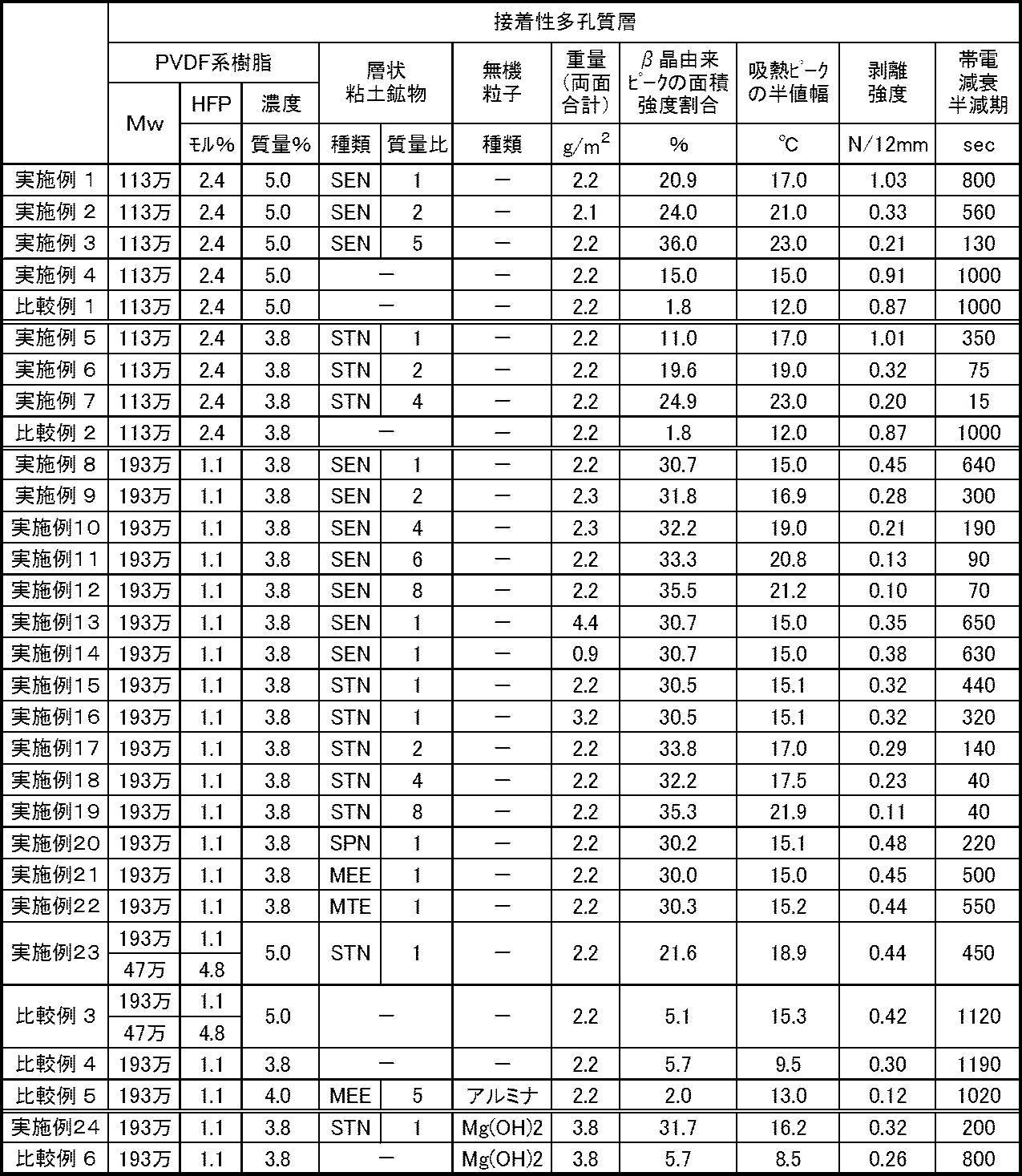
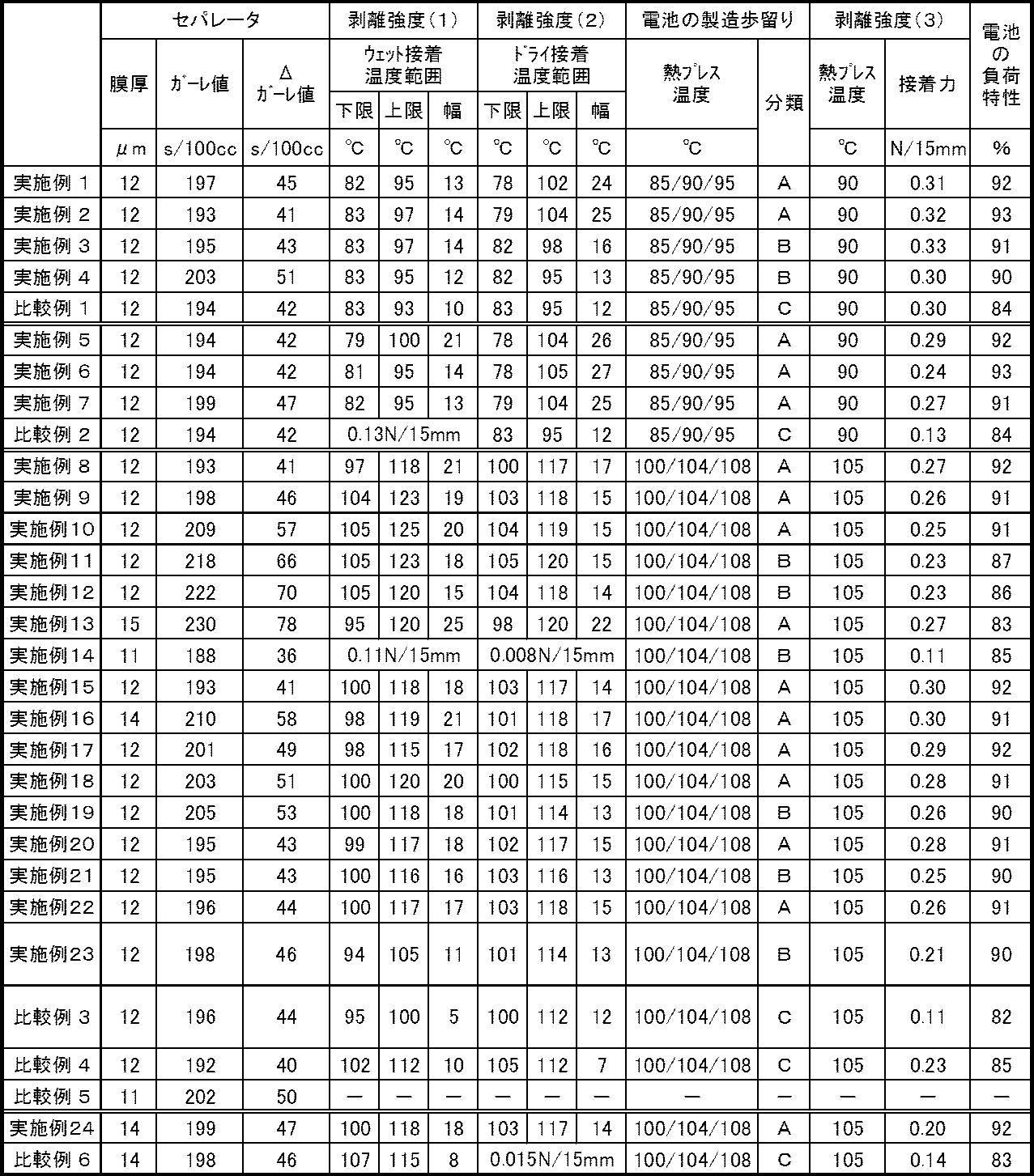
Claims (15)
- 多孔質基材と、
前記多孔質基材の片面又は両面に設けられ、ポリフッ化ビニリデン系樹脂を含む接着性多孔質層と、
を備え、
前記接着性多孔質層は、X線回折法で測定して得たX線回折スペクトルにおいて、ポリフッ化ビニリデン系樹脂のα晶由来ピークの面積強度とポリフッ化ビニリデン系樹脂のβ晶由来ピークの面積強度との合計に占めるポリフッ化ビニリデン系樹脂のβ晶由来ピークの面積強度の割合が10%以上100%以下である、
非水系二次電池用セパレータ。 - 前記接着性多孔質層は、X線回折法で測定して得たX線回折スペクトルにおいて、ポリフッ化ビニリデン系樹脂のα晶由来ピークの面積強度とポリフッ化ビニリデン系樹脂のβ晶由来ピークの面積強度との合計に占めるポリフッ化ビニリデン系樹脂のβ晶由来ピークの面積強度の割合が10%以上35%以下である、請求項1に記載の非水系二次電池用セパレータ。
- 前記接着性多孔質層は、示差走査熱量測定を行って得た示差走査熱量曲線において、吸熱ピークの半値幅が15℃以上30℃以下である、請求項1又は請求項2に記載の非水系二次電池用セパレータ。
- 前記接着性多孔質層がさらに結晶形態制御剤を含む、請求項1~請求項3のいずれか一項に記載の非水系二次電池用セパレータ。
- 前記結晶形態制御剤が層状粘土鉱物である、請求項4に記載の非水系二次電池用セパレータ。
- 前記層状粘土鉱物が、ヘクトライト、サポナイト、スチブンサイト、バイデライト、モンモリロナイト及び膨潤性雲母からなる群より選ばれる少なくとも1種を含む、請求項5に記載の非水系二次電池用セパレータ。
- 前記層状粘土鉱物が、インターカレート剤による処理を施された層状粘土鉱物である、請求項5又は請求項6に記載の非水系二次電池用セパレータ。
- 前記層状粘土鉱物が、有機オニウムイオンを層間に有する層状粘土鉱物である、請求項5~請求項7のいずれか一項に記載の非水系二次電池用セパレータ。
- 前記接着性多孔質層に含まれる前記ポリフッ化ビニリデン系樹脂と前記層状粘土鉱物の質量比が99.9:0.1~95.0:5.0である、請求項5~請求項8のいずれか一項に記載の非水系二次電池用セパレータ。
- 前記接着性多孔質層の重量が前記多孔質基材の片面において0.5g/m2以上2.0g/m2以下である、請求項1~請求項9のいずれか一項に記載の非水系二次電池用セパレータ。
- 前記多孔質基材と前記接着性多孔質層との間の剥離強度が0.20N/12mm以上1.20N/12mm以下である、請求項1~請求項10のいずれか一項に記載の非水系二次電池用セパレータ。
- 前記非水系二次電池用セパレータのガーレ値から前記多孔質基材のガーレ値を減算した値が、90秒/100cc以下である、請求項1~請求項11のいずれか一項に記載の非水系二次電池用セパレータ。
- 前記接着性多孔質層がさらに金属水酸化物粒子及び金属酸化物粒子からなる群より選ばれる少なくとも1種の粒子を含み、
前記接着性多孔質層における前記粒子の含有量が、前記ポリフッ化ビニリデン系樹脂と前記粒子の合計量に対して10質量%以上80質量%未満である、請求項1~請求項12のいずれか一項に記載の非水系二次電池用セパレータ。 - 多孔質基材と、
前記多孔質基材の片面又は両面に設けられ、ポリフッ化ビニリデン系樹脂及び層状粘土鉱物を含む接着性多孔質層と、
を備え、
前記接着性多孔質層の重量が前記多孔質基材の片面において0.5g/m2以上2.0g/m2以下である、
非水系二次電池用セパレータ。 - 正極と、負極と、前記正極及び前記負極の間に配置された請求項1~請求項14のいずれか一項に記載の非水系二次電池用セパレータと、を備え、リチウムのドープ・脱ドープにより起電力を得る非水系二次電池。
Priority Applications (5)
| Application Number | Priority Date | Filing Date | Title |
|---|---|---|---|
| US15/552,847 US20180047962A1 (en) | 2015-03-24 | 2016-03-22 | Separator for a non-aqueous secondary battery, and non-aqueous secondary battery |
| JP2016551871A JP6096395B2 (ja) | 2015-03-24 | 2016-03-22 | 非水系二次電池用セパレータ及び非水系二次電池 |
| CN201680010432.8A CN107210414A (zh) | 2015-03-24 | 2016-03-22 | 非水系二次电池用隔膜及非水系二次电池 |
| KR1020177022771A KR102556362B1 (ko) | 2015-03-24 | 2016-03-22 | 비수계 이차전지용 세퍼레이터 및 비수계 이차전지 |
| US15/930,586 US11183735B2 (en) | 2015-03-24 | 2020-05-13 | Separator for a non-aqueous secondary battery, and non-aqueous secondary battery |
Applications Claiming Priority (4)
| Application Number | Priority Date | Filing Date | Title |
|---|---|---|---|
| JP2015-061570 | 2015-03-24 | ||
| JP2015061570 | 2015-03-24 | ||
| JP2015111461 | 2015-06-01 | ||
| JP2015-111461 | 2015-06-01 |
Related Child Applications (2)
| Application Number | Title | Priority Date | Filing Date |
|---|---|---|---|
| US15/552,847 A-371-Of-International US20180047962A1 (en) | 2015-03-24 | 2016-03-22 | Separator for a non-aqueous secondary battery, and non-aqueous secondary battery |
| US15/930,586 Continuation US11183735B2 (en) | 2015-03-24 | 2020-05-13 | Separator for a non-aqueous secondary battery, and non-aqueous secondary battery |
Publications (1)
| Publication Number | Publication Date |
|---|---|
| WO2016152863A1 true WO2016152863A1 (ja) | 2016-09-29 |
Family
ID=56978538
Family Applications (1)
| Application Number | Title | Priority Date | Filing Date |
|---|---|---|---|
| PCT/JP2016/059011 Ceased WO2016152863A1 (ja) | 2015-03-24 | 2016-03-22 | 非水系二次電池用セパレータ及び非水系二次電池 |
Country Status (5)
| Country | Link |
|---|---|
| US (2) | US20180047962A1 (ja) |
| JP (2) | JP6096395B2 (ja) |
| KR (1) | KR102556362B1 (ja) |
| CN (1) | CN107210414A (ja) |
| WO (1) | WO2016152863A1 (ja) |
Cited By (29)
| Publication number | Priority date | Publication date | Assignee | Title |
|---|---|---|---|---|
| JP2017066356A (ja) * | 2016-02-10 | 2017-04-06 | 住友化学株式会社 | 多孔質層、積層体、多孔質層を含む非水電解液二次電池用部材、および多孔質層を含む非水電解液二次電池 |
| JP2017092050A (ja) * | 2017-02-24 | 2017-05-25 | 住友化学株式会社 | 多孔質層、積層体、多孔質層を含む非水電解液二次電池用部材、および多孔質層を含む非水電解液二次電池 |
| JP2017168419A (ja) * | 2016-03-11 | 2017-09-21 | 住友化学株式会社 | 多孔質層 |
| JP2017226117A (ja) * | 2016-06-21 | 2017-12-28 | 住友化学株式会社 | 積層体 |
| US9991489B2 (en) | 2015-10-02 | 2018-06-05 | Sumitomo Chemical Company, Limited | Porous layer, laminated body, nonaqueous electrolyte secondary battery member including the porous layer, and nonaqueous electrolyte secondary battery including the porous layer |
| JP2018133246A (ja) * | 2017-02-16 | 2018-08-23 | 帝人株式会社 | 非水系二次電池用セパレータ及び非水系二次電池 |
| JP2018181648A (ja) * | 2017-04-14 | 2018-11-15 | 住友化学株式会社 | 非水電解液二次電池用絶縁性多孔質層 |
| WO2018212252A1 (ja) * | 2017-05-17 | 2018-11-22 | 帝人株式会社 | 非水系二次電池用セパレータ、非水系二次電池および非水系二次電池の製造方法 |
| KR20190042715A (ko) | 2016-12-27 | 2019-04-24 | 도레이 카부시키가이샤 | 전지용 세퍼레이터, 전극체 및 비수 전해질 이차전지 |
| US10361418B2 (en) | 2016-06-21 | 2019-07-23 | Sumitomo Chemical Company, Limited | Laminated body |
| US10361458B2 (en) | 2016-06-21 | 2019-07-23 | Sumitomo Chemical Company, Limited | Laminated body |
| KR20190088567A (ko) | 2017-03-17 | 2019-07-26 | 도레이 카부시키가이샤 | 전지용 세퍼레이터, 전극체 및 비수 전해질 이차전지 |
| US10367182B2 (en) | 2016-06-21 | 2019-07-30 | Sumitomo Chemical Company, Limited | Laminated body |
| US10388932B2 (en) | 2016-06-21 | 2019-08-20 | Sumitomo Chemical Company, Limited | Laminated body |
| US10461297B2 (en) | 2016-06-21 | 2019-10-29 | Sumitomo Chemical Company, Limited | Laminated body |
| US10476066B2 (en) | 2016-06-21 | 2019-11-12 | Sumitomo Chemical Company, Limited | Laminated body |
| CN111357133A (zh) * | 2017-11-30 | 2020-06-30 | 帝人株式会社 | 非水系二次电池用隔膜及非水系二次电池 |
| US10950838B2 (en) | 2017-12-19 | 2021-03-16 | Sumitomo Chemical Company, Limited | Nonaqueous electrolyte secondary battery |
| US10957941B2 (en) | 2017-12-19 | 2021-03-23 | Sumitomo Chemical Company, Limited | Nonaqueous electrolyte secondary battery |
| US11038208B2 (en) | 2017-12-19 | 2021-06-15 | Sumitomo Chemical Company, Limited | Nonaqueous electrolyte secondary battery |
| US11094997B2 (en) | 2017-05-29 | 2021-08-17 | Sumitomo Chemical Company, Limited | Nonaqueous electrolyte secondary battery |
| US11158907B2 (en) | 2017-12-19 | 2021-10-26 | Sumitomo Chemical Company, Limited | Nonaqueous electrolyte secondary battery |
| US11158883B2 (en) | 2017-12-19 | 2021-10-26 | Sumitomo Chemical Company, Limited | Nonaqueous electrolyte secondary battery |
| US11205799B2 (en) | 2017-12-19 | 2021-12-21 | Sumitomo Chemical Company, Limited | Nonaqueous electrolyte secondary battery |
| JP2022529150A (ja) * | 2019-05-03 | 2022-06-17 | エルジー エナジー ソリューション リミテッド | リチウム-硫黄電池用分離膜及びこれを含むリチウム-硫黄電池 |
| JP2022536509A (ja) * | 2019-06-14 | 2022-08-17 | エルジー エナジー ソリューション リミテッド | セパレータ及びそれを含む電気化学素子 |
| JP2023025920A (ja) * | 2021-08-11 | 2023-02-24 | プライムプラネットエナジー&ソリューションズ株式会社 | 電池の製造方法 |
| JP2023025919A (ja) * | 2021-08-11 | 2023-02-24 | プライムプラネットエナジー&ソリューションズ株式会社 | 電池の製造方法 |
| WO2023053821A1 (ja) * | 2021-09-30 | 2023-04-06 | 東レ株式会社 | 多孔性フィルム、二次電池用セパレータおよび二次電池 |
Families Citing this family (25)
| Publication number | Priority date | Publication date | Assignee | Title |
|---|---|---|---|---|
| CN107210414A (zh) | 2015-03-24 | 2017-09-26 | 帝人株式会社 | 非水系二次电池用隔膜及非水系二次电池 |
| JPWO2019044918A1 (ja) * | 2017-08-30 | 2020-08-13 | 東レ株式会社 | 高分子膜形成装置、高分子膜形成方法およびセパレータの製造方法 |
| JP6684963B2 (ja) * | 2017-12-18 | 2020-04-22 | 日本碍子株式会社 | Ldhセパレータ及び亜鉛二次電池 |
| JP6430619B1 (ja) * | 2017-12-19 | 2018-11-28 | 住友化学株式会社 | 非水電解液二次電池 |
| JP6430622B1 (ja) * | 2017-12-19 | 2018-11-28 | 住友化学株式会社 | 非水電解液二次電池 |
| WO2019181286A1 (ja) * | 2018-03-20 | 2019-09-26 | 三洋電機株式会社 | 非水電解質二次電池及び非水電解質二次電池の製造方法 |
| JP7020221B2 (ja) * | 2018-03-20 | 2022-02-16 | 住友大阪セメント株式会社 | 静電チャック装置 |
| TWI803648B (zh) * | 2018-06-12 | 2023-06-01 | 南韓商Lg化學股份有限公司 | 含無機塗層的電化學裝置用之隔板及彼之製造方法 |
| WO2020099351A1 (en) | 2018-11-12 | 2020-05-22 | Fischer Eco Solutions Gmbh | Method for bonding two plates together for a fuel cell, especially gluing bipolar plates in a fuel cell |
| WO2020184351A1 (ja) * | 2019-03-13 | 2020-09-17 | 東レ株式会社 | 非水二次電池用セパレータ及び非水二次電池 |
| JP6903090B2 (ja) * | 2019-04-01 | 2021-07-14 | 旭化成株式会社 | 蓄電デバイス用セパレータ、及びそれを用いた捲回体、リチウムイオン二次電池、並びに蓄電デバイス |
| JP7495266B2 (ja) | 2019-04-18 | 2024-06-04 | 住友化学株式会社 | 電池用セパレータの製造システムおよび製造方法 |
| JP7351906B2 (ja) * | 2019-05-13 | 2023-09-27 | 旭化成株式会社 | 蓄電デバイス用セパレータ及び蓄電デバイス |
| KR102485668B1 (ko) * | 2019-05-17 | 2023-01-05 | 주식회사 엘지에너지솔루션 | 전기화학소자용 분리막 및 이를 포함하는 전기화학소자 |
| CN110289382A (zh) * | 2019-07-23 | 2019-09-27 | 深圳锂硫科技有限公司 | 一种锂电池隔膜的制备方法及锂电池隔膜 |
| WO2021029629A1 (ko) * | 2019-08-14 | 2021-02-18 | 주식회사 엘지화학 | 개선된 전극접착력 및 저항 특성을 갖는 리튬이차전지용 분리막 및 상기 분리막을 포함하는 리튬이차전지 |
| US20230120595A1 (en) * | 2020-04-17 | 2023-04-20 | Shenzhen Senior Technology Material Co., Ltd. | Composition, composite separator and preparation method therefor, and lithium ion battery |
| CN115668625B (zh) * | 2020-07-17 | 2026-04-10 | 株式会社Lg新能源 | 用于二次电池的隔板、制造该隔板的方法和包括该隔板的二次电池 |
| EP4190860A4 (en) * | 2020-07-28 | 2024-04-10 | Teijin Limited | NON-AQUEOUS SECONDARY BATTERY |
| CN112563665B (zh) * | 2020-12-10 | 2023-06-02 | 珠海冠宇电池股份有限公司 | 一种锂离子电池 |
| KR102875681B1 (ko) * | 2020-12-29 | 2025-10-23 | 주식회사 엘지에너지솔루션 | 전기화학소자용 분리막 제조 방법 및 상기 제조 방법에 의해서 제조된 전기화학소자용 분리막 |
| JP7412374B2 (ja) * | 2021-02-22 | 2024-01-12 | プライムプラネットエナジー&ソリューションズ株式会社 | 二次電池および二次電池の製造方法 |
| CN114258602B (zh) * | 2021-03-30 | 2023-12-19 | 宁德新能源科技有限公司 | 一种电化学装置和电子装置 |
| US20220367975A1 (en) * | 2021-05-12 | 2022-11-17 | Enevate Corporation | Configuring cell performance using specific anode, cathode, and separator combinations |
| WO2025264032A1 (ko) * | 2024-06-20 | 2025-12-26 | 주식회사 엘지에너지솔루션 | 전기화학소자용 분리막 및 이를 포함하는 전기화학소자 |
Citations (3)
| Publication number | Priority date | Publication date | Assignee | Title |
|---|---|---|---|---|
| JP2011075714A (ja) * | 2009-09-29 | 2011-04-14 | Gunze Ltd | 画像形成装置用転写ベルト |
| WO2014136838A1 (ja) * | 2013-03-06 | 2014-09-12 | 帝人株式会社 | 非水系二次電池用セパレータおよび非水系二次電池 |
| JP5876616B1 (ja) * | 2014-04-11 | 2016-03-02 | 東レバッテリーセパレータフィルム株式会社 | 電池用セパレータ |
Family Cites Families (20)
| Publication number | Priority date | Publication date | Assignee | Title |
|---|---|---|---|---|
| TW342537B (en) * | 1995-03-03 | 1998-10-11 | Atochem North America Elf | Polymeric electrode, electrolyte, article of manufacture and composition |
| US6743876B2 (en) * | 1997-02-28 | 2004-06-01 | Atofina Chemicals, Inc. | Copolymers of vinylidene fluoride and hexafluoropropylene having reduced extractable content and improved solution clarity |
| JPWO2002091514A1 (ja) * | 2001-05-09 | 2004-08-26 | 日本電池株式会社 | 非水電解質電池およびその製造方法 |
| US20040241550A1 (en) | 2003-05-28 | 2004-12-02 | Wensley C. Glen | Battery separator for lithium polymer battery |
| KR101110264B1 (ko) | 2003-11-19 | 2012-03-13 | 도레이 도넨 기노마쿠 고도가이샤 | 복합 미다공막 및 그 제조 방법과 용도 |
| JP2006073221A (ja) | 2004-08-31 | 2006-03-16 | Teijin Ltd | リチウムイオン二次電池用セパレータ及びリチウムイオン二次電池 |
| JP2006120462A (ja) * | 2004-10-21 | 2006-05-11 | Sanyo Electric Co Ltd | 非水電解質電池 |
| US7829219B2 (en) * | 2004-12-23 | 2010-11-09 | Ecopro Co. Ltd. | Cathode for lithium secondary batteries having improved coating properties and lithium secondary batteries using the same |
| JP5319947B2 (ja) * | 2008-03-25 | 2013-10-16 | 株式会社東芝 | 非水電解質電池 |
| JP2010123383A (ja) * | 2008-11-19 | 2010-06-03 | Teijin Ltd | 非水系二次電池用セパレータ、その製造方法および非水系二次電池 |
| JP5664138B2 (ja) * | 2010-11-08 | 2015-02-04 | ソニー株式会社 | 耐収縮性微多孔膜、電池用セパレータ及びリチウムイオン二次電池 |
| US9065119B2 (en) * | 2011-04-08 | 2015-06-23 | Teijin Limited | Separator for nonaqueous secondary battery, and nonaqueous secondary battery |
| JP5129895B2 (ja) * | 2011-04-08 | 2013-01-30 | 帝人株式会社 | 非水系二次電池用セパレータおよび非水系二次電池 |
| US9269938B2 (en) * | 2011-04-08 | 2016-02-23 | Teijin Limited | Separator for nonaqueous secondary battery, and nonaqueous secondary battery |
| TWI501451B (zh) | 2011-04-08 | 2015-09-21 | 帝人股份有限公司 | Non-aqueous secondary battery separator and non-aqueous secondary battery |
| TWI553945B (zh) * | 2011-10-21 | 2016-10-11 | 帝人股份有限公司 | 非水系蓄電池用分隔器及非水系蓄電池 |
| CN103891002B (zh) | 2011-10-21 | 2017-03-15 | 帝人株式会社 | 非水系二次电池用隔膜及非水系二次电池 |
| JP6285454B2 (ja) * | 2012-11-09 | 2018-02-28 | イーエヌティー テクノロジーズ, インコーポレイテッド | エンティティ・ネットワーク・トランスレーション(ent) |
| KR20140113186A (ko) * | 2013-03-15 | 2014-09-24 | 삼성에스디아이 주식회사 | 전극 조립체 및 이를 이용한 이차전지의 제조방법 |
| CN107210414A (zh) | 2015-03-24 | 2017-09-26 | 帝人株式会社 | 非水系二次电池用隔膜及非水系二次电池 |
-
2016
- 2016-03-22 CN CN201680010432.8A patent/CN107210414A/zh active Pending
- 2016-03-22 WO PCT/JP2016/059011 patent/WO2016152863A1/ja not_active Ceased
- 2016-03-22 KR KR1020177022771A patent/KR102556362B1/ko active Active
- 2016-03-22 JP JP2016551871A patent/JP6096395B2/ja active Active
- 2016-03-22 US US15/552,847 patent/US20180047962A1/en not_active Abandoned
-
2017
- 2017-02-14 JP JP2017024858A patent/JP6178939B2/ja active Active
-
2020
- 2020-05-13 US US15/930,586 patent/US11183735B2/en active Active
Patent Citations (3)
| Publication number | Priority date | Publication date | Assignee | Title |
|---|---|---|---|---|
| JP2011075714A (ja) * | 2009-09-29 | 2011-04-14 | Gunze Ltd | 画像形成装置用転写ベルト |
| WO2014136838A1 (ja) * | 2013-03-06 | 2014-09-12 | 帝人株式会社 | 非水系二次電池用セパレータおよび非水系二次電池 |
| JP5876616B1 (ja) * | 2014-04-11 | 2016-03-02 | 東レバッテリーセパレータフィルム株式会社 | 電池用セパレータ |
Non-Patent Citations (2)
| Title |
|---|
| CUI, ZHAOLIANG ET AL.: "Recent progress in fluoropolymers for membranes", PROGRESS IN POLYMER SCIENCE, vol. 39, 2014, pages 164 - 198, XP055299292 * |
| KIM, YOUNG-JIN ET AL.: "Characteristics of electrospun PVDF/SiO2 composite nanofiber membranes as polymer electrolyte", MATERIALS CHEMISTRY AND PHYSICS, vol. 127, 2011, pages 137 - 142, XP028167705 * |
Cited By (38)
| Publication number | Priority date | Publication date | Assignee | Title |
|---|---|---|---|---|
| US9991489B2 (en) | 2015-10-02 | 2018-06-05 | Sumitomo Chemical Company, Limited | Porous layer, laminated body, nonaqueous electrolyte secondary battery member including the porous layer, and nonaqueous electrolyte secondary battery including the porous layer |
| JP2017066356A (ja) * | 2016-02-10 | 2017-04-06 | 住友化学株式会社 | 多孔質層、積層体、多孔質層を含む非水電解液二次電池用部材、および多孔質層を含む非水電解液二次電池 |
| JP2017168419A (ja) * | 2016-03-11 | 2017-09-21 | 住友化学株式会社 | 多孔質層 |
| JP2017226117A (ja) * | 2016-06-21 | 2017-12-28 | 住友化学株式会社 | 積層体 |
| US10367182B2 (en) | 2016-06-21 | 2019-07-30 | Sumitomo Chemical Company, Limited | Laminated body |
| US10476066B2 (en) | 2016-06-21 | 2019-11-12 | Sumitomo Chemical Company, Limited | Laminated body |
| US10461297B2 (en) | 2016-06-21 | 2019-10-29 | Sumitomo Chemical Company, Limited | Laminated body |
| US10361418B2 (en) | 2016-06-21 | 2019-07-23 | Sumitomo Chemical Company, Limited | Laminated body |
| US10361458B2 (en) | 2016-06-21 | 2019-07-23 | Sumitomo Chemical Company, Limited | Laminated body |
| US10388932B2 (en) | 2016-06-21 | 2019-08-20 | Sumitomo Chemical Company, Limited | Laminated body |
| KR20190042715A (ko) | 2016-12-27 | 2019-04-24 | 도레이 카부시키가이샤 | 전지용 세퍼레이터, 전극체 및 비수 전해질 이차전지 |
| JP2018133246A (ja) * | 2017-02-16 | 2018-08-23 | 帝人株式会社 | 非水系二次電池用セパレータ及び非水系二次電池 |
| JP2017092050A (ja) * | 2017-02-24 | 2017-05-25 | 住友化学株式会社 | 多孔質層、積層体、多孔質層を含む非水電解液二次電池用部材、および多孔質層を含む非水電解液二次電池 |
| KR20190088567A (ko) | 2017-03-17 | 2019-07-26 | 도레이 카부시키가이샤 | 전지용 세퍼레이터, 전극체 및 비수 전해질 이차전지 |
| JP2018181648A (ja) * | 2017-04-14 | 2018-11-15 | 住友化学株式会社 | 非水電解液二次電池用絶縁性多孔質層 |
| JP6487130B1 (ja) * | 2017-05-17 | 2019-03-20 | 帝人株式会社 | 非水系二次電池用セパレータ、非水系二次電池および非水系二次電池の製造方法 |
| WO2018212252A1 (ja) * | 2017-05-17 | 2018-11-22 | 帝人株式会社 | 非水系二次電池用セパレータ、非水系二次電池および非水系二次電池の製造方法 |
| US11094997B2 (en) | 2017-05-29 | 2021-08-17 | Sumitomo Chemical Company, Limited | Nonaqueous electrolyte secondary battery |
| CN111357133B (zh) * | 2017-11-30 | 2022-10-25 | 帝人株式会社 | 非水系二次电池用隔膜及非水系二次电池 |
| CN111357133A (zh) * | 2017-11-30 | 2020-06-30 | 帝人株式会社 | 非水系二次电池用隔膜及非水系二次电池 |
| US11158883B2 (en) | 2017-12-19 | 2021-10-26 | Sumitomo Chemical Company, Limited | Nonaqueous electrolyte secondary battery |
| US11158907B2 (en) | 2017-12-19 | 2021-10-26 | Sumitomo Chemical Company, Limited | Nonaqueous electrolyte secondary battery |
| US10957941B2 (en) | 2017-12-19 | 2021-03-23 | Sumitomo Chemical Company, Limited | Nonaqueous electrolyte secondary battery |
| US11205799B2 (en) | 2017-12-19 | 2021-12-21 | Sumitomo Chemical Company, Limited | Nonaqueous electrolyte secondary battery |
| US11038208B2 (en) | 2017-12-19 | 2021-06-15 | Sumitomo Chemical Company, Limited | Nonaqueous electrolyte secondary battery |
| US10950838B2 (en) | 2017-12-19 | 2021-03-16 | Sumitomo Chemical Company, Limited | Nonaqueous electrolyte secondary battery |
| JP2022529150A (ja) * | 2019-05-03 | 2022-06-17 | エルジー エナジー ソリューション リミテッド | リチウム-硫黄電池用分離膜及びこれを含むリチウム-硫黄電池 |
| JP7176135B2 (ja) | 2019-05-03 | 2022-11-21 | エルジー エナジー ソリューション リミテッド | リチウム-硫黄電池用分離膜及びこれを含むリチウム-硫黄電池 |
| JP7322192B2 (ja) | 2019-06-14 | 2023-08-07 | エルジー エナジー ソリューション リミテッド | セパレータ及びそれを含む電気化学素子 |
| JP2022536509A (ja) * | 2019-06-14 | 2022-08-17 | エルジー エナジー ソリューション リミテッド | セパレータ及びそれを含む電気化学素子 |
| JP2023025919A (ja) * | 2021-08-11 | 2023-02-24 | プライムプラネットエナジー&ソリューションズ株式会社 | 電池の製造方法 |
| JP2023025920A (ja) * | 2021-08-11 | 2023-02-24 | プライムプラネットエナジー&ソリューションズ株式会社 | 電池の製造方法 |
| JP7426358B2 (ja) | 2021-08-11 | 2024-02-01 | プライムプラネットエナジー&ソリューションズ株式会社 | 電池の製造方法 |
| JP2024156972A (ja) * | 2021-08-11 | 2024-11-06 | プライムプラネットエナジー&ソリューションズ株式会社 | 電池の製造方法 |
| JP7594508B2 (ja) | 2021-08-11 | 2024-12-04 | プライムプラネットエナジー&ソリューションズ株式会社 | 電池の製造方法 |
| US12224393B2 (en) | 2021-08-11 | 2025-02-11 | Prime Planet Energy & Solutions, Inc. | Method of manufacturing battery |
| JP7710576B2 (ja) | 2021-08-11 | 2025-07-18 | プライムプラネットエナジー&ソリューションズ株式会社 | 電池の製造方法 |
| WO2023053821A1 (ja) * | 2021-09-30 | 2023-04-06 | 東レ株式会社 | 多孔性フィルム、二次電池用セパレータおよび二次電池 |
Also Published As
| Publication number | Publication date |
|---|---|
| JP6096395B2 (ja) | 2017-03-15 |
| JPWO2016152863A1 (ja) | 2017-04-27 |
| US20200274121A1 (en) | 2020-08-27 |
| JP6178939B2 (ja) | 2017-08-09 |
| US11183735B2 (en) | 2021-11-23 |
| US20180047962A1 (en) | 2018-02-15 |
| KR20170130368A (ko) | 2017-11-28 |
| CN107210414A (zh) | 2017-09-26 |
| JP2017135111A (ja) | 2017-08-03 |
| KR102556362B1 (ko) | 2023-07-18 |
Similar Documents
| Publication | Publication Date | Title |
|---|---|---|
| JP6178939B2 (ja) | 非水系二次電池用セパレータ及び非水系二次電池 | |
| JP6171117B1 (ja) | 非水系二次電池用セパレータ及び非水系二次電池 | |
| JP6205525B1 (ja) | 非水系二次電池用セパレータ及び非水系二次電池 | |
| JP6143992B1 (ja) | 非水系二次電池用セパレータ及び非水系二次電池 | |
| JP6665345B2 (ja) | 非水系二次電池用セパレータ及び非水系二次電池 | |
| EP3627586B1 (en) | Separator for non-aqueous secondary batteries, non-aqueous secondary battery, and method for producing non-aqueous secondary battery | |
| JP6078703B1 (ja) | 非水系二次電池用セパレータ、非水系二次電池及び非水系二次電池の製造方法 | |
| CN108448033A (zh) | 非水系二次电池用隔膜和非水系二次电池 | |
| EP3920266B1 (en) | Separator for non-aqueous secondary cell, and non-aqueous secondary cell | |
| JP6371905B2 (ja) | 非水系二次電池用セパレータ及び非水系二次電池 | |
| JP2019216033A (ja) | 非水系二次電池用セパレータ及び非水系二次電池 | |
| KR102935259B1 (ko) | 비수계 이차전지용 세퍼레이터 및 비수계 이차전지 | |
| JP7482935B2 (ja) | 非水系二次電池用セパレータ及び非水系二次電池 | |
| JP2016181439A (ja) | 非水系二次電池用セパレータ及び非水系二次電池 | |
| JP7411005B2 (ja) | 非水系二次電池用セパレータ及び非水系二次電池 | |
| JP7483154B2 (ja) | 非水系二次電池用セパレータ及び非水系二次電池 | |
| JP7781266B2 (ja) | 非水系二次電池用セパレータ及び非水系二次電池 |
Legal Events
| Date | Code | Title | Description |
|---|---|---|---|
| ENP | Entry into the national phase |
Ref document number: 2016551871 Country of ref document: JP Kind code of ref document: A |
|
| 121 | Ep: the epo has been informed by wipo that ep was designated in this application |
Ref document number: 16768766 Country of ref document: EP Kind code of ref document: A1 |
|
| ENP | Entry into the national phase |
Ref document number: 20177022771 Country of ref document: KR Kind code of ref document: A |
|
| WWE | Wipo information: entry into national phase |
Ref document number: 15552847 Country of ref document: US |
|
| NENP | Non-entry into the national phase |
Ref country code: DE |
|
| 122 | Ep: pct application non-entry in european phase |
Ref document number: 16768766 Country of ref document: EP Kind code of ref document: A1 |