WO2016140324A1 - 冷蔵庫およびその製造方法 - Google Patents
冷蔵庫およびその製造方法 Download PDFInfo
- Publication number
- WO2016140324A1 WO2016140324A1 PCT/JP2016/056658 JP2016056658W WO2016140324A1 WO 2016140324 A1 WO2016140324 A1 WO 2016140324A1 JP 2016056658 W JP2016056658 W JP 2016056658W WO 2016140324 A1 WO2016140324 A1 WO 2016140324A1
- Authority
- WO
- WIPO (PCT)
- Prior art keywords
- door frame
- adhesive
- transparent plate
- door
- surface portion
- Prior art date
Links
Images


Classifications
-
- F—MECHANICAL ENGINEERING; LIGHTING; HEATING; WEAPONS; BLASTING
- F25—REFRIGERATION OR COOLING; COMBINED HEATING AND REFRIGERATION SYSTEMS; HEAT PUMP SYSTEMS; MANUFACTURE OR STORAGE OF ICE; LIQUEFACTION SOLIDIFICATION OF GASES
- F25D—REFRIGERATORS; COLD ROOMS; ICE-BOXES; COOLING OR FREEZING APPARATUS NOT OTHERWISE PROVIDED FOR
- F25D23/00—General constructional features
- F25D23/02—Doors; Covers
Definitions
- the present invention relates to a refrigerator and a manufacturing method thereof, and more particularly to a refrigerator including a door whose front surface is covered with a transparent plate material such as a glass plate and a manufacturing method thereof.
- a general refrigerator has a plurality of storage rooms in the refrigerator body, and a refrigerator room, a freezer room, and a vegetable room are sequentially arranged from above. Moreover, the front opening of a refrigerator compartment, a freezer compartment, and a vegetable compartment is closed by the door which has a heat insulation structure.
- the front surface of the door frame is closed by a front plate
- the rear surface of the door frame is closed by a rear plate.
- a space surrounded by the door frame, the front plate, and the rear plate is filled with a foam heat insulating material such as urethane foam.
- Patent Document 1 discloses a refrigerator having a door provided with a door front plate made of a glass plate. Specifically, referring to FIG. 1 of this document and the explanation thereof, the front surface of the door outer frame 9 is covered with a door front plate 8 made of glass, and the rear surface of the door outer frame 9 is covered with a door rear plate 14. ing. A vacuum heat insulating panel 10 is disposed in an internal space surrounded by the door outer frame 9, the door front plate 8 and the door outer frame 9. Further, referring to FIG. 3 and the explanation thereof, the peripheral portion of the front plate 8 is bonded to the door outer frame 9 through a double-sided adhesive tape 17.
- a refrigerator having a door whose front surface is made of a glass plate is disclosed.
- the front surface of the edge frame 24 is closed with a transparent front plate 25, and the rear surface of the edge frame 24 is closed with an inner box frame 23.
- the internal space surrounded by the edge frame 24, the transparent front plate 25 and the inner box frame 23 is filled with foamed urethane 29.
- the peripheral portion of the transparent front plate 25 is bonded to the front surface of the edge frame 24 via a double-sided tape 30.
- Patent Document 3 referring to each drawing of this document, the front surface of the door frame 12 is closed with glass 11a, the rear surface of the door frame 12 is closed with a door inner plate 14, and the foam heat insulating material 15 is placed in the internal space surrounded by these. Filled. Moreover, the outer peripheral edge part of the glass 11a is being fixed to the door frame 12 with the outer plate fixing tape 13 stuck from the inner side.
- JP 2014-66442 A JP 2014-55767 A JP-A-5-322436
- the glass plate disposed on the front surface is bonded to the door frame via a double-sided tape.
- the adhesive strength of double-sided tape is not always large, so in order to firmly bond the glass plate to the door frame, a large bonding area is required on the side of the door frame to be bonded, which increases the size of the door frame. This hindered the weight and size reduction of the door itself.
- the present invention has been made in view of the above problems, and an object of the present invention is to provide a refrigerator including a door with an optimized bonding structure between a transparent plate and a door frame, and a method for manufacturing the refrigerator.
- the refrigerator of the present invention includes a refrigerator main body having an opening formed on the front surface, and a door that closes the opening.
- the door has a door frame that has a frame shape, and a transparent adhesive bonded to the door frame from the front surface.
- a plate member, an inner plate member joined to the door frame from the rear surface, and a foam heat insulating material filled in a space surrounded by the door frame, the transparent plate member and the inner plate member, and the door frame includes the door frame, A side surface portion constituting a side surface of the door; and an adhesive surface portion to which the transparent plate material is bonded; and the transparent plate material is bonded to the adhesive surface portion of the door frame via an adhesive, and the door frame
- a groove portion is provided by denting the vicinity of the outer peripheral portion of the bonding surface portion.
- the refrigerator according to the present invention is characterized in that the groove portion is formed continuously along the side of the bonding surface portion.
- the refrigerator according to the present invention is characterized in that a protruding portion is provided by partially protruding the adhesive surface portion of the region overlapping with the transparent plate material in the thickness direction.
- the refrigerator of the present invention is characterized in that the projecting portions are discretely formed along the side of the adhesive surface portion.
- the refrigerator of the present invention is characterized in that the adhesive has a thickness of 0.5 mm to 1.5 mm.
- the present invention is a method of manufacturing a refrigerator including a door that closes the front opening of the refrigerator main body, has a frame shape, and includes a side surface portion that forms an outer peripheral side surface of the door, and an adhesive surface portion that is continuous with the side surface portion.
- a step of preparing a door frame a step of applying an adhesive to the adhesive surface portion of the door frame, a step of placing a transparent plate on the upper surface of the door frame, and a step of pressure-bonding the transparent plate to the door frame
- the adhesive that moves outward between the adhesive surface portion of the door frame and the transparent plate material is caused to flow into a groove portion in which the door frame is recessed by pressing the door frame against the door frame.
- the transparent plate material comes into contact with a protruding portion in which the adhesive surface portion of the region overlapping with the transparent plate material is partially protruded in the thickness direction, The transparent plate material is pressed.
- a refrigerator main body having an opening formed on the front surface, and a door that closes the opening, the door is bonded to the door frame from the front surface, and a door frame having a frame shape.
- a transparent plate member, an inner plate member joined to the door frame from the rear surface, and a foam heat insulating material filled in a space surrounded by the door frame, the transparent plate member and the inner plate member, and the door frame is ,
- a groove is provided by recessing the vicinity of the outer peripheral portion of the bonding surface portion of the door frame.
- the said groove part is continuously formed along the side of the said adhesion surface part.
- plate material is partially protruded in the thickness direction, and the protrusion part is provided.
- the thickness of the adhesive is ensured to be equal to or greater than a predetermined value, and the strain accompanying the temperature change under the usage condition can be absorbed by the adhesive.
- the protruding portions are discretely formed along the side edges of the bonding surface portion. Therefore, at the time of manufacture, the flow of the liquid or semi-solid adhesive is not hindered by the protrusions, and the adhesive can be sufficiently distributed between the door frame and the transparent member.
- the thickness of the said adhesive agent is 0.5 mm or more and 1.5 mm or less. Therefore, the temperature distortion due to the difference in thermal expansion coefficient between the glass plate and the door frame is absorbed by the deformation of the adhesive.
- a manufacturing method of a refrigerator provided with a door that closes the front opening of the refrigerator main body, has a frame shape, configures an outer peripheral side surface of the door, and an adhesive surface portion that is continuous with the side surface portion.
- a step of preparing a door frame a step of applying an adhesive to the bonding surface portion of the door frame, a step of placing a transparent plate on the upper surface of the door frame, and a pressure bonding of the transparent plate to the door frame
- a step of incorporating an inner plate material into the door frame from the rear and filling a space surrounded by the door frame, the transparent plate material and the inner plate material with a foam heat insulating material, and in the crimping step By pressing the transparent plate material against the door frame, the adhesive that moves outward between the adhesive surface portion of the door frame and the transparent plate material is caused to flow into the groove portion in which the door frame is recessed. Therefore, the outflow of the adhesive to the outside is prevented by causing the adhesive that moves outward in the crimping process to flow into the groove.
- the transparent plate material comes into contact with a protruding portion in which the adhesive surface portion of the region overlapping with the transparent plate material is partially protruded in the thickness direction. Until the transparent plate is pressed. Therefore, it becomes possible to make the thickness of the adhesive within a predetermined range by crimping the transparent plate material until the transparent plate material comes into contact with the protruding portion.
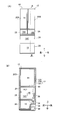
- FIG. 1 It is a figure which shows the refrigerator of this invention, (A) is a front view which shows a refrigerator entirely, (B) is the sectional drawing. It is a figure which shows the refrigerator of this invention, (A) is an exploded perspective view which shows a door, (B) is sectional drawing of a door. It is a figure which shows the refrigerator of this invention, (A) is a perspective view which shows a door frame, (B) and (C) are sectional drawings which show a door frame. It is a flowchart which shows the manufacturing method of the refrigerator of this invention. It is a figure which shows the manufacturing method of the refrigerator of this invention, and is a figure which shows arrangement
- FIG. 1A is a front view generally showing the refrigerator 10
- FIG. 1B is a cross-sectional view of the refrigerator 10 taken along line BB of FIG. 1A.
- the configuration and the like of the refrigerator 10 will be described using the vertical and horizontal directions as appropriate.
- the left-right direction indicates a direction when the refrigerator 10 is viewed from the front.
- the refrigerator 10 includes a refrigerator body 12 that is a heat insulating box, and a storage room for storing food and the like is formed inside the refrigerator body 12.
- a refrigerator room 14 As the storage room, a refrigerator room 14, an ice making room 16A, an upper freezer room 16B, a lower freezer room 16C, and a vegetable room 18 are formed from above.
- the ice making room 16A, the upper freezing room 16B, and the lower freezing room 16C are formed by dividing one storage, and these may be collectively referred to as the freezing room 16 in the following description.
- the basic function of the refrigerator 10 is to cool an object to be stored such as food stored in each storage room to a predetermined temperature.
- the internal temperature of the refrigerator compartment 14 is a refrigerator temperature range
- the internal temperature of the freezer compartment 16 is a freezing temperature region
- the internal temperature of the vegetable compartment 18 is a refrigerator temperature region.
- the front surface of the refrigerator main body 12 is open, and doors are provided at the opening portions of the storage rooms so that the doors can be opened and closed.
- the door 20A that closes the left side portion of the refrigerator compartment 14 is rotatably supported by the refrigerator main body 12 at the left upper and lower ends, and the door 20B that closes the right side portion of the refrigerator compartment 14 has the right upper and lower ends at the refrigerator main body 12. It is supported rotatably.
- the ice making room 16A, the upper freezing room 16B, the lower freezing room 16C, and the vegetable room 18 are respectively closed by doors 22, 24, 26, and 28 that can be pulled out.
- refrigerator main body 12 of refrigerator 10 is provided with an outer box 12A made of steel plate having an opening on the front surface, and a gap on the inner side of outer box 12A and opened on the front surface. And an inner box 12B made of synthetic resin having a portion, and a heat insulating material 12C made of polyurethane foam filled and foamed in a gap between the outer box 12A and the inner box 12B.
- the doors 20A to 28 that close the front opening of the refrigerator main body 12 employ the same heat insulating structure as the refrigerator main body 12. Further, as shown in FIG. 1B, a heat insulating partition wall 30 is disposed between the refrigerator compartment 14 and the freezer compartment 16, and a heat insulating partition wall 32 is also provided between the freezer compartment 16 and the vegetable compartment 18. Is arranged. These heat insulating partition walls 30 and 32 also adopt the same heat insulating structure as the refrigerator main body 12.
- a cooler 38 which is an evaporator for cooling the air circulating through each storage chamber, is disposed inside the cooling chamber formed behind the lower freezing chamber 16C. Further, a compressor 36 is disposed in a machine room 34 that is defined behind the vegetable compartment 18 of the refrigerator body 12. The cooler 38 is connected to the compressor 36, a radiator (not shown), a capillary tube (not shown) or an expansion valve via a refrigerant pipe, and constitutes a vapor compression refrigeration cycle circuit.
- the front surfaces of the doors 20A to 28 are made of a transparent plate made of glass in order to improve the design.
- FIG. 2A is a perspective view showing a state in which the door 20A is disassembled in the front-rear direction
- FIG. 2B is a lower cross-sectional view of the door 20A.
- the door 20A is joined to the door frame 42 from the rear surface, the door frame 42 having a substantially frame shape, the transparent plate member 40 made of glass bonded to the front surface of the door frame 42, and the door frame 42. And an inner plate 44 as a panel.
- an internal space surrounded by the door frame 42, the transparent plate member 40, and the inner plate member 44 is filled with a foam heat insulating material 46 as shown in FIG. 2B in order to give the door 20A heat insulation. .
- a foam heat insulating material 46 as shown in FIG. 2B in order to give the door 20A heat insulation.
- Such a heat insulating structure is the same for the other doors 20B to 20 shown in FIG.
- the transparent plate 40 is a glass plate having a rectangular shape when viewed from the front, and is subjected to a predetermined coloring process.
- a transparent glass plate whose back surface is painted may be used, or coloring with colored glass may be used.
- the design property is improved by disposing the transparent plate material 40 made of colored glass on the front surface of the door 20A, and further, the mechanical strength of the entire door 20A is improved.
- the transparent plate 40 is bonded to the door frame 42 via an adhesive as will be described later.
- the door frame 42 is a frame member that has a substantially frame shape when viewed from the front.
- the door frame 42 constitutes a side surface portion of the door 20A, and is a transparent plate member 40, an inner plate member 44, and a foam heat insulating material 46, which are other components constituting the door 20A.
- the door frame 42 is made of ABS resin integrally formed by injection molding.
- On the front surface of the door frame 42 a flat surface for bonding the above-described transparent plate material 40 is formed.
- the rear surface of the door frame 42 has a shape that facilitates adhesion and bonding of the inner plate member 44. The shape of the door frame 42 will be described later with reference to FIG.
- the inner plate member 44 is a plate-like member having a rectangular shape when viewed from the front, and has a role of closing the door frame 42 from the rear. Similar to the door frame 42, the inner plate 44 is made of an integrally molded ABS resin. The inner plate member 44 is partially formed with a protrusion for storing an object to be stored such as a plastic bottle on the rear side surface of the door 20A.
- the foam heat insulating material 46 is filled in the internal space surrounded by the door frame 42, the transparent plate material 40, and the inner plate material 44, and has a function of thermally insulating the refrigerator compartment 14 (FIG. 1A) closed by the door 20A. .
- the material of the foam heat insulating material 46 for example, foamed urethane is employed.
- the schematic configuration of the door 20A is as described above, but the embodied door 20A is in close contact with the refrigerator main body, a gasket provided on the periphery of the rear surface of the door 20A, in addition to the above-described members. Magnets and the like.
- FIG. 3A is a perspective view showing the door frame 42
- FIG. 3B is a cross-sectional view taken along line BB in FIG. 3A
- FIG. 3C is FIG. 3B. It is sectional drawing which expands and shows the important point of.
- the transparent plate member 40 is also shown together with the door frame 42.
- the door frame 42 has four side surfaces constituting the side surface of the door, specifically, an upper side surface portion 48A, a lower side surface portion 48B, a left side surface portion 48C, and a right side surface portion 48D.
- these four side portions may be collectively referred to as a side portion 48.
- An adhesive surface portion 50 is formed as a flat surface extending inward from the front end portions of the upper side surface portion 48A, the lower side surface portion 48B, the left side surface portion 48C, and the right side surface portion 48D.
- the bonding surface portion 50 is a portion for bonding the transparent plate material 40 made of glass, and has a flat surface corresponding to the peripheral portion of the transparent plate material 40.
- a crosspiece 43 is installed between the left side surface portion 48C and the right side surface portion 48D.
- a plurality of crosspieces 43 are installed at equal intervals in the vertical direction.
- an adhesive surface portion 50 is formed upward from the front end portion of the lower side surface portion 48 ⁇ / b> B of the door frame 42, and the transparent plate member 40 is bonded to the front surface of the adhesive surface portion 50. Yes.
- the transparent plate member 40 is bonded to the bonding surface portion 50 via an adhesive 58.
- only the lower part of the bonding surface portion 50 is bonded to the transparent plate member 40 via the adhesive 58, but the entire bonding surface portion 50 may be bonded to the transparent plate member 40 via the bonding agent 58.
- thermoplastic adhesive is employed as the adhesive 58 used in this embodiment.
- the adhesive 58 of this embodiment exhibits a strong adhesive force as compared with the adhesive tape used in the background art. Therefore, since the area required for bonding the transparent plate member 40 to the door frame 42 can be reduced, the height L1 of the bonding surface portion 50 can be reduced, and the resin material constituting the door frame 42 can be saved. And the weight reduction of the door frame 42 is implement
- the groove portion 52 is formed by recessing the vicinity of the outer peripheral portion of the bonding surface portion 50 into a rectangular shape.
- the groove portion 52 is formed along the upper side surface portion 48A, the lower side surface portion 48B, the left side surface portion 48C, and the right side surface portion 48D shown in FIG.
- the groove portion 52 may be formed continuously along the upper side surface portion 48A, the lower side surface portion 48B, the left side surface portion 48C, and the right side surface portion 48D shown in FIG. 3A, or may be formed discretely.
- the role of the groove 52 is to store the adhesive 58 used for bonding the transparent plate 40.
- the adhesive 58 By storing the adhesive 58 in the groove 52, it is possible to prevent the liquid or semi-solid adhesive 58 from leaking to the outside in the middle of the manufacturing process. Moreover, the effect which the adhesive strength of the adhesive agent 58 and the door frame 42 improves by filling the groove part 52 with the adhesive agent 58 is also anticipated.
- the depth L3 of the groove 52 based on the main surface 50A of the adhesive surface 50 is, for example, not less than 0.5 mm and not more than 1.5 mm. If it is this range, the adhesive agent 58 which moves outside at the process of adhere
- the protruding portion 56 is formed by partially protruding the main surface 50A of the bonding surface portion 50 forward.
- the protrusion 56 is formed adjacent to the groove 52 and has a substantially cylindrical shape protruding forward.
- the protruding portion 56 is discretely, intermittently or continuously formed along the upper side surface portion 48A, the lower side surface portion 48B, the left side surface portion 48C and the right side surface portion 48D shown in FIG.
- the transparent plate member 40 can be stably separated by the protruding portions 56 by providing the protruding portions 56 at least at the four corners of the door frame 42.
- the protruding portions 56 By forming the protruding portions 56 discretely, the flow of the adhesive in the bonding process at the time of manufacturing described below is not hindered by the protruding portions 56. Therefore, as shown in FIG. 3B, the adhesive 58 can be sufficiently spread between the adhesive surface portion 50 of the door frame 42 and the transparent plate member 40. Further, in the bonding process, it is possible to favorably flow the adhesive into the groove 52 shown in FIG.
- the protruding portion 56 By forming the protruding portion 56 on the bonding surface portion 50, the front surface of the protruding portion 56 comes into contact with the rear main surface of the transparent plate member 40. Can be separated accordingly.
- the thickness of the adhesive 58 that bonds the transparent plate member 40 and the bonding surface portion 50 is secured to the same level as the protruding portion 56. Therefore, the thermal expansion coefficient is different between the transparent plate material 40 made of glass and the door frame 42 made of ABS resin, so that even if temperature distortion occurs under the usage conditions, the adhesive 58 deforms the temperature distortion. Can be relaxed. As a result, the transparent plate member 40 and the door frame 42 are prevented from being deformed or damaged due to temperature distortion.
- the protrusion 56 is adjacent to the groove 52, but the groove 52 and the protrusion 56 may be separated from each other.
- the height L2 of the protruding portion 56 with respect to the main surface 50A of the bonding surface portion 50 is, for example, not less than 0.5 mm and not more than 1.5 mm.
- the thickness of the adhesive 58 is also defined in the same range, and the effect of absorbing the above-described temperature strain can be achieved.
- the height L2 of the protrusion 56 is less than 0.5 mm, it is considered that the thickness of the adhesive 58 is not sufficiently ensured and the temperature strain is not sufficiently absorbed by the adhesive 58.
- the height L2 of the protrusion part 56 is longer than 1.5 mm, it is possible that the thickness of the whole door will increase excessively.
- the wall portion 54 is formed by protruding the outer peripheral end portion of the bonding surface portion 50 forward.
- the wall portion 54 is continuously formed along the upper side surface portion 48A, the lower side surface portion 48B, the left side surface portion 48C, and the right side surface portion 48D shown in FIG.
- the cross-sectional shape of the wall portion 54 is such that the front end surface exhibits an inclined surface in consideration of contact with the end portion of the transparent plate member 40.
- the height L4 of the wall portion 54 with respect to the main surface 50A of the bonding surface portion 50 is, for example, not less than 0.5 mm and not more than 1.5 mm.
- the interference with the transparent plate member 40 can be suppressed while preventing the adhesive 58 from flowing out to the outside.
- the height L4 of the wall portion 54 is less than 0.5 mm, the adhesive 58 once stored in the groove portion 52 in the middle of the manufacturing process may flow out to the outside beyond the wall portion 54. There is. If the height L4 of the wall 54 is longer than 1.5 mm, the tip of the wall 54 may interfere with the transparent plate 40 in the process of assembling the transparent plate 40 to the door frame 42.
- the manufacturing method of the refrigerator of this form WHEREIN The process S11 which prepares a door frame etc., the process S12 which applies an adhesive agent to a door frame, and mounts a transparent board
- FIG. 5 shows a manufacturing apparatus such as a belt conveyor used in the manufacturing method of the refrigerator of this embodiment.
- the transparent plate material 40A, the door frame 42A, the door frame 42B, and the transparent plate material 40B are placed on the belt conveyors 60, 62, 64, and 66, respectively.
- the belt conveyors 60, 62, 64 and 66 convey these at a predetermined speed.
- the transparent plate material 40A, the door frame 42A, the door frame 42B, and the transparent plate material 40B are put into positions indicated by P1 on the belt conveyors 60, 62, 64, and 66.
- the belt conveyors 60, 62, 64, and 66 convey each member placed on the upper surface from the left to the right on the paper surface at the same speed. Moreover, the belt conveyor 60 and the belt conveyor 62 are used as a pair in order to manufacture a door. The belt conveyor 64 and the belt conveyor 66 are used as a pair in order to manufacture another door. Thus, by arranging two sets of belt conveyors 60, 62, 64, 66 for manufacturing doors close to each other, a coating device 68, a crimping device 70, and a transfer robot 72 described later can be shared. , Production efficiency can be improved.
- an adhesive is applied to the door frame 42 in step S12. Specifically, first, by rotating the belt conveyors 62 and 64 shown in FIG. 5, the door frames 42A and 42B placed on the upper surfaces thereof are conveyed to a position indicated by P2. As a result, the door frames 42 ⁇ / b> A and 42 ⁇ / b> B placed on the belt conveyors 62 and 64 are disposed below the coating device 68. At the same time, the transparent plate members 40A and 40B placed on the belt conveyors 60 and 66 are also conveyed to the position indicated by P2.
- FIG. 6A is a perspective view showing this step
- FIG. 6B is a cross-sectional perspective view showing the door frame 42 after application is completed.
- door frame 42 has four side surfaces, specifically, upper side surface portion 48A, lower side surface portion 48B, left side surface portion 48C, and right side surface portion 48D, and these side surface portions.
- An adhesive surface portion 50 extends inward from the end portion of each. In this step, the adhesive 58 is applied to the upper surface of the adhesive surface portion 50.
- the adhesive used in this embodiment is a hot melt adhesive, that is, a thermoplastic adhesive, and is heated to about 100 degrees to be in a liquid or semi-solid state, and the adhesive surface portion of the door frame 42 50 is applied.
- the adhesive 58 is continuously applied so as to draw a rectangle on the upper surface of the adhesive surface portion 50 using the nozzle 74 provided in the application device 68 (FIG. 5).
- the adhesive 58 is applied on the main surface 50A of the bonding surface portion 50 so as to be in a bead shape. Further, the adhesive 58 is applied on the inner side of the protrusion 56 on the main surface 50 ⁇ / b> A of the adhesive surface portion 50. By doing in this way, the adhesive agent 58 can be spread over the whole inner part of 50 A of main surfaces in the process after crimping
- one coating device 68 is provided for the door frame 42 ⁇ / b> A placed on the upper surface of the belt conveyor 62 and the door frame 42 ⁇ / b> B placed on the upper surface of the belt conveyor 64. It is possible to perform the coating process all at once. Thereby, there is an advantage that the manufacturing equipment is simplified and the manufacturing cost is reduced.
- step S13 the transparent plate 40 is placed on the upper surface of the door frame 42 to which the adhesive 58 has been applied.
- the transparent plate material 40A, the door frame 42A, the door frame 42B, and the transparent plate material 40B placed on these upper surfaces are changed to P3. Move to the position indicated by.
- the transparent plate 40A placed on the upper surface of the belt conveyor 60 was placed on the upper surface of the belt conveyor 62. It mounts on the upper surface of the door frame 42A.
- the transfer robot 72 performs the transfer operation while adsorbing the upper surface of the transparent plate 40A made of glass.
- the transfer robot 72 places the transparent plate 40 ⁇ / b> B placed on the upper surface of the belt conveyor 66 on the upper surface of the door frame 42 ⁇ / b> B placed on the upper surface of the belt conveyor 64.
- the belt conveyor 62 and the belt conveyor 64 are adjacent to each other, there is an advantage that the above-described transfer operation can be performed collectively by one transfer robot 72 disposed between them.
- the transparent plate 40 is placed so as to close the upper surface of the door frame 42.
- the adhesive 58 is applied in a bead shape along the bonding surface portion 50 of the door frame 42, the entire outer peripheral portion of the transparent plate 40 is bonded to the bonding surface portion 50 of the door frame 42.
- the transparent plate 40 is firmly bonded to the door frame 42.
- the transparent plate 40 is pressure-bonded to the door frame 42 in step S14.
- the door frames 42A and 42B are moved to a point indicated by P4.
- the door frames 42 ⁇ / b> A and 42 ⁇ / b> B are arranged below the crimping device 70.
- Transparent plate members 40A and 40B are placed on the upper surfaces of the door frames 42A and 42B in the previous step.
- a pressing force is evenly applied from above to the transparent plate material 40 placed on the upper surface of the door frame 42.
- the adhesive 58 is pushed by the transparent plate material 40, and the adhesive 58 spreads suitably between the door frame 42 and the transparent plate material 40.
- the transparent plate member 40 is pressed against the door frame 42, and the lower peripheral portion of the transparent plate member 40 comes into contact with the upper surface of the protruding portion 56 of the door frame 42.
- the protruding portion 56 protrudes upward from the main surface 50A of the bonding surface portion 0.5 mm to 1.5 mm. Therefore, the adhesive 58 disposed between the main surface 50A of the adhesive surface portion 50 and the transparent plate member 40 also has the same thickness (0.5 mm to 1.5 mm) as the protruding portion 56. When the adhesive 58 is in such a thickness range, even if temperature distortion occurs between the transparent plate member 40 and the door frame 42 under use conditions, the adhesive 58 that bonds the two deforms. The temperature distortion is relieved.
- the liquid or semi-solid adhesive 58 spreads outside by pressing the transparent plate 40 to the door frame 42.
- the adhesive 58 that is going to move outward is caused to flow into the groove 52.
- the groove 52 is formed sufficiently deep, for example, about 0.5 mm to 1.5 mm. Therefore, the adhesive 58 moving toward the outside is stored in the groove portion 52, and the outflow of the adhesive 58 to the outside is prevented.
- the protrusions 56 are formed discretely, so that the spread of the adhesive 58 is not hindered by the protrusions 56. Therefore, the adhesive 58 can be spread to the outer peripheral end of the transparent plate 40. For the same reason, since the flow of the adhesive 58 flowing into the groove 52 is not hindered by the protrusion 56, the surplus adhesive 58 is stored in the groove 52 and is prevented from flowing out. Yes.
- a wall 54 protruding upward is formed outside the groove 52.
- the height at which the wall portion 54 protrudes upward is about 0.5 mm to 1.5 mm, and is sufficiently high. Therefore, the outflow of the adhesive 58 stored in the groove 52 to the outside is prevented by the presence of the wall 54.
- the door frames 42A and 42B are moved to the position indicated by P5 by rotating the belt conveyors 62 and 64 with reference to FIG. Thereafter, the door frames 42A and 42B are taken out from the belt conveyors 62 and 64.
- the adhesive 58 is cooled and hardened.
- the adhesive 58 used in this embodiment is of a thermoplastic type, but has a property that it completely cures when it absorbs moisture in the air and does not soften even after heating.
- step S16 the inner plate material is incorporated and the heat insulating material is filled.
- an inner plate member 44 is incorporated in the rear main surface of the door frame 42.
- the inner plate member 44 may be assembled by fitting the outer peripheral end portion of the inner plate member 44 to the door frame 42 or bonding the outer peripheral end portion of the inner plate member 44 to the door frame 42.
- a foam heat insulating material 46 such as urethane foam is filled in the internal space surrounded by the door frame 42, the transparent plate material 40 and the inner plate material 44.
- Another member such as a gasket is attached to the door frame 42 to manufacture the door 20A shown in FIG.
- other doors 20B to 20 shown in FIG. 1A are also manufactured by the same manufacturing method.
- the refrigerator 10 is manufactured by attaching these doors 20A to 28 together with other members to the refrigerator main body 12.
Priority Applications (1)
| Application Number | Priority Date | Filing Date | Title |
|---|---|---|---|
| CN201680009317.9A CN107850370A (zh) | 2015-03-03 | 2016-03-03 | 冰箱及其制造方法 |
Applications Claiming Priority (2)
| Application Number | Priority Date | Filing Date | Title |
|---|---|---|---|
| JP2015040906A JP6469480B2 (ja) | 2015-03-03 | 2015-03-03 | 冷蔵庫およびその製造方法 |
| JP2015-040906 | 2015-03-03 |
Publications (1)
| Publication Number | Publication Date |
|---|---|
| WO2016140324A1 true WO2016140324A1 (ja) | 2016-09-09 |
Family
ID=56844817
Family Applications (1)
| Application Number | Title | Priority Date | Filing Date |
|---|---|---|---|
| PCT/JP2016/056658 WO2016140324A1 (ja) | 2015-03-03 | 2016-03-03 | 冷蔵庫およびその製造方法 |
Country Status (3)
| Country | Link |
|---|---|
| JP (1) | JP6469480B2 (zh) |
| CN (1) | CN107850370A (zh) |
| WO (1) | WO2016140324A1 (zh) |
Cited By (2)
| Publication number | Priority date | Publication date | Assignee | Title |
|---|---|---|---|---|
| TWI682139B (zh) * | 2018-03-13 | 2020-01-11 | 日商三菱電機股份有限公司 | 冰箱及該冰箱的製造方法 |
| WO2022208787A1 (ja) * | 2021-03-31 | 2022-10-06 | 三菱電機株式会社 | 冷蔵庫 |
Families Citing this family (10)
| Publication number | Priority date | Publication date | Assignee | Title |
|---|---|---|---|---|
| JP6707066B2 (ja) * | 2017-10-26 | 2020-06-10 | 日立グローバルライフソリューションズ株式会社 | 冷蔵庫 |
| JP2019138533A (ja) * | 2018-02-09 | 2019-08-22 | 日立グローバルライフソリューションズ株式会社 | 冷蔵庫 |
| CN109708379B (zh) * | 2017-10-26 | 2020-10-30 | 日立环球生活方案株式会社 | 冰箱 |
| JP2019132507A (ja) * | 2018-01-31 | 2019-08-08 | 日立グローバルライフソリューションズ株式会社 | 冷蔵庫 |
| JP2019138536A (ja) * | 2018-02-09 | 2019-08-22 | 日立グローバルライフソリューションズ株式会社 | 冷蔵庫 |
| JP7177903B2 (ja) * | 2018-02-09 | 2022-11-24 | 日立グローバルライフソリューションズ株式会社 | 冷蔵庫 |
| JP2019196856A (ja) * | 2018-05-09 | 2019-11-14 | 日立グローバルライフソリューションズ株式会社 | 冷蔵庫 |
| JP7129922B2 (ja) * | 2019-01-23 | 2022-09-02 | 日立グローバルライフソリューションズ株式会社 | 冷蔵庫 |
| JP7261758B2 (ja) * | 2020-02-28 | 2023-04-20 | 日立グローバルライフソリューションズ株式会社 | 扉及びこの製造方法並びに扉を備えた冷蔵庫 |
| JP7063974B2 (ja) * | 2020-12-01 | 2022-05-09 | 日立グローバルライフソリューションズ株式会社 | 冷蔵庫 |
Citations (8)
| Publication number | Priority date | Publication date | Assignee | Title |
|---|---|---|---|---|
| JPS57157982A (en) * | 1981-03-26 | 1982-09-29 | Tokyo Shibaura Electric Co | Manufacture of heat insulated door |
| JPS6218412U (zh) * | 1985-07-18 | 1987-02-03 | ||
| JPH0328313U (zh) * | 1989-07-28 | 1991-03-20 | ||
| JPH0526570A (ja) * | 1991-07-16 | 1993-02-02 | Matsushita Refrig Co Ltd | 断熱扉の製造方法 |
| JP2004060814A (ja) * | 2002-07-30 | 2004-02-26 | Komatsu Ltd | 摺動部構造体及び軸受装置 |
| JP2013160388A (ja) * | 2012-02-01 | 2013-08-19 | Sharp Corp | 冷蔵庫の扉、およびこれを備えた冷蔵庫 |
| DE102012106200A1 (de) * | 2012-07-10 | 2014-01-16 | Remis Gesellschaft für Entwicklung und Vertrieb von technischen Elementen mbH | Kühlschrank |
| JP2016044816A (ja) * | 2014-08-19 | 2016-04-04 | 株式会社東芝 | 貯蔵庫 |
Family Cites Families (4)
| Publication number | Priority date | Publication date | Assignee | Title |
|---|---|---|---|---|
| JP2594813Y2 (ja) * | 1991-09-13 | 1999-05-10 | 旭光学工業株式会社 | 接着部材 |
| KR100662101B1 (ko) * | 2005-01-06 | 2006-12-27 | 주식회사 엘지화학 | 플라스틱제 판넬 |
| JP5488747B2 (ja) * | 2012-08-06 | 2014-05-14 | パナソニック株式会社 | 冷蔵庫 |
| CN103644698B (zh) * | 2013-12-06 | 2016-04-27 | 合肥美的电冰箱有限公司 | 门体和冰箱 |
-
2015
- 2015-03-03 JP JP2015040906A patent/JP6469480B2/ja active Active
-
2016
- 2016-03-03 WO PCT/JP2016/056658 patent/WO2016140324A1/ja active Application Filing
- 2016-03-03 CN CN201680009317.9A patent/CN107850370A/zh active Pending
Patent Citations (8)
| Publication number | Priority date | Publication date | Assignee | Title |
|---|---|---|---|---|
| JPS57157982A (en) * | 1981-03-26 | 1982-09-29 | Tokyo Shibaura Electric Co | Manufacture of heat insulated door |
| JPS6218412U (zh) * | 1985-07-18 | 1987-02-03 | ||
| JPH0328313U (zh) * | 1989-07-28 | 1991-03-20 | ||
| JPH0526570A (ja) * | 1991-07-16 | 1993-02-02 | Matsushita Refrig Co Ltd | 断熱扉の製造方法 |
| JP2004060814A (ja) * | 2002-07-30 | 2004-02-26 | Komatsu Ltd | 摺動部構造体及び軸受装置 |
| JP2013160388A (ja) * | 2012-02-01 | 2013-08-19 | Sharp Corp | 冷蔵庫の扉、およびこれを備えた冷蔵庫 |
| DE102012106200A1 (de) * | 2012-07-10 | 2014-01-16 | Remis Gesellschaft für Entwicklung und Vertrieb von technischen Elementen mbH | Kühlschrank |
| JP2016044816A (ja) * | 2014-08-19 | 2016-04-04 | 株式会社東芝 | 貯蔵庫 |
Cited By (2)
| Publication number | Priority date | Publication date | Assignee | Title |
|---|---|---|---|---|
| TWI682139B (zh) * | 2018-03-13 | 2020-01-11 | 日商三菱電機股份有限公司 | 冰箱及該冰箱的製造方法 |
| WO2022208787A1 (ja) * | 2021-03-31 | 2022-10-06 | 三菱電機株式会社 | 冷蔵庫 |
Also Published As
| Publication number | Publication date |
|---|---|
| JP6469480B2 (ja) | 2019-02-13 |
| JP2016161219A (ja) | 2016-09-05 |
| CN107850370A (zh) | 2018-03-27 |
Similar Documents
| Publication | Publication Date | Title |
|---|---|---|
| JP6469480B2 (ja) | 冷蔵庫およびその製造方法 | |
| US9303915B2 (en) | Refrigerator and method of manufacturing door thereof | |
| CN104567215B (zh) | 冰箱门及冰箱 | |
| RU2571031C2 (ru) | Холодильный аппарат, в частности бытовой холодильный аппарат | |
| RU2562207C2 (ru) | Холодильный аппарат, в частности, бытовой холодильный аппарат | |
| JP6964810B2 (ja) | 冷蔵庫 | |
| CN206709470U (zh) | 冰箱 | |
| WO2016163250A1 (ja) | 冷蔵庫及び冷蔵庫の製造方法 | |
| CN205448472U (zh) | 隔热箱体、隔热门以及冰箱 | |
| JP2013245918A (ja) | 断熱箱体およびその製造方法、冷蔵庫 | |
| JP2021119325A (ja) | 冷蔵庫 | |
| WO2014021018A1 (ja) | 断熱箱体の製造方法、断熱箱体及び冷蔵庫 | |
| JP7261459B2 (ja) | 冷蔵庫およびその製造方法 | |
| JP6113610B2 (ja) | 冷蔵庫 | |
| JP7287643B2 (ja) | 冷蔵庫およびその製造方法 | |
| JP2019132501A (ja) | 冷蔵庫 | |
| JP2014066493A (ja) | 断熱箱体、断熱箱体の製造方法及び冷蔵庫 | |
| EP3819571B1 (en) | Refrigerator appliance | |
| JP6774274B2 (ja) | 冷蔵庫 | |
| CN116772505A (zh) | 一种家电透明门、冰箱、装配方法 | |
| JP6113612B2 (ja) | 真空断熱材及びこれを用いた冷蔵庫 | |
| JP2014047966A (ja) | 断熱箱体及び冷蔵庫 | |
| CN108981274A (zh) | 冰箱 | |
| JP2019138511A (ja) | 冷蔵庫及び保冷機器扉の製造方法 | |
| JP2005202560A (ja) | 断熱筺体および断熱仕切り板 |
Legal Events
| Date | Code | Title | Description |
|---|---|---|---|
| 121 | Ep: the epo has been informed by wipo that ep was designated in this application |
Ref document number: 16759016 Country of ref document: EP Kind code of ref document: A1 |
|
| NENP | Non-entry into the national phase |
Ref country code: DE |
|
| 122 | Ep: pct application non-entry in european phase |
Ref document number: 16759016 Country of ref document: EP Kind code of ref document: A1 |