WO2016140324A1 - 冷蔵庫およびその製造方法 - Google Patents
冷蔵庫およびその製造方法 Download PDFInfo
- Publication number
- WO2016140324A1 WO2016140324A1 PCT/JP2016/056658 JP2016056658W WO2016140324A1 WO 2016140324 A1 WO2016140324 A1 WO 2016140324A1 JP 2016056658 W JP2016056658 W JP 2016056658W WO 2016140324 A1 WO2016140324 A1 WO 2016140324A1
- Authority
- WO
- WIPO (PCT)
- Prior art keywords
- door frame
- adhesive
- transparent plate
- door
- surface portion
- Prior art date
Links
Images


Classifications
-
- F—MECHANICAL ENGINEERING; LIGHTING; HEATING; WEAPONS; BLASTING
- F25—REFRIGERATION OR COOLING; COMBINED HEATING AND REFRIGERATION SYSTEMS; HEAT PUMP SYSTEMS; MANUFACTURE OR STORAGE OF ICE; LIQUEFACTION SOLIDIFICATION OF GASES
- F25D—REFRIGERATORS; COLD ROOMS; ICE-BOXES; COOLING OR FREEZING APPARATUS NOT OTHERWISE PROVIDED FOR
- F25D23/00—General constructional features
- F25D23/02—Doors; Covers
Definitions
- the present invention relates to a refrigerator and a manufacturing method thereof, and more particularly to a refrigerator including a door whose front surface is covered with a transparent plate material such as a glass plate and a manufacturing method thereof.
- a general refrigerator has a plurality of storage rooms in the refrigerator body, and a refrigerator room, a freezer room, and a vegetable room are sequentially arranged from above. Moreover, the front opening of a refrigerator compartment, a freezer compartment, and a vegetable compartment is closed by the door which has a heat insulation structure.
- the front surface of the door frame is closed by a front plate
- the rear surface of the door frame is closed by a rear plate.
- a space surrounded by the door frame, the front plate, and the rear plate is filled with a foam heat insulating material such as urethane foam.
- Patent Document 1 discloses a refrigerator having a door provided with a door front plate made of a glass plate. Specifically, referring to FIG. 1 of this document and the explanation thereof, the front surface of the door outer frame 9 is covered with a door front plate 8 made of glass, and the rear surface of the door outer frame 9 is covered with a door rear plate 14. ing. A vacuum heat insulating panel 10 is disposed in an internal space surrounded by the door outer frame 9, the door front plate 8 and the door outer frame 9. Further, referring to FIG. 3 and the explanation thereof, the peripheral portion of the front plate 8 is bonded to the door outer frame 9 through a double-sided adhesive tape 17.
- a refrigerator having a door whose front surface is made of a glass plate is disclosed.
- the front surface of the edge frame 24 is closed with a transparent front plate 25, and the rear surface of the edge frame 24 is closed with an inner box frame 23.
- the internal space surrounded by the edge frame 24, the transparent front plate 25 and the inner box frame 23 is filled with foamed urethane 29.
- the peripheral portion of the transparent front plate 25 is bonded to the front surface of the edge frame 24 via a double-sided tape 30.
- Patent Document 3 referring to each drawing of this document, the front surface of the door frame 12 is closed with glass 11a, the rear surface of the door frame 12 is closed with a door inner plate 14, and the foam heat insulating material 15 is placed in the internal space surrounded by these. Filled. Moreover, the outer peripheral edge part of the glass 11a is being fixed to the door frame 12 with the outer plate fixing tape 13 stuck from the inner side.
- JP 2014-66442 A JP 2014-55767 A JP-A-5-322436
- the glass plate disposed on the front surface is bonded to the door frame via a double-sided tape.
- the adhesive strength of double-sided tape is not always large, so in order to firmly bond the glass plate to the door frame, a large bonding area is required on the side of the door frame to be bonded, which increases the size of the door frame. This hindered the weight and size reduction of the door itself.
- the present invention has been made in view of the above problems, and an object of the present invention is to provide a refrigerator including a door with an optimized bonding structure between a transparent plate and a door frame, and a method for manufacturing the refrigerator.
- the refrigerator of the present invention includes a refrigerator main body having an opening formed on the front surface, and a door that closes the opening.
- the door has a door frame that has a frame shape, and a transparent adhesive bonded to the door frame from the front surface.
- a plate member, an inner plate member joined to the door frame from the rear surface, and a foam heat insulating material filled in a space surrounded by the door frame, the transparent plate member and the inner plate member, and the door frame includes the door frame, A side surface portion constituting a side surface of the door; and an adhesive surface portion to which the transparent plate material is bonded; and the transparent plate material is bonded to the adhesive surface portion of the door frame via an adhesive, and the door frame
- a groove portion is provided by denting the vicinity of the outer peripheral portion of the bonding surface portion.
- the refrigerator according to the present invention is characterized in that the groove portion is formed continuously along the side of the bonding surface portion.
- the refrigerator according to the present invention is characterized in that a protruding portion is provided by partially protruding the adhesive surface portion of the region overlapping with the transparent plate material in the thickness direction.
- the refrigerator of the present invention is characterized in that the projecting portions are discretely formed along the side of the adhesive surface portion.
- the refrigerator of the present invention is characterized in that the adhesive has a thickness of 0.5 mm to 1.5 mm.
- the present invention is a method of manufacturing a refrigerator including a door that closes the front opening of the refrigerator main body, has a frame shape, and includes a side surface portion that forms an outer peripheral side surface of the door, and an adhesive surface portion that is continuous with the side surface portion.
- a step of preparing a door frame a step of applying an adhesive to the adhesive surface portion of the door frame, a step of placing a transparent plate on the upper surface of the door frame, and a step of pressure-bonding the transparent plate to the door frame
- the adhesive that moves outward between the adhesive surface portion of the door frame and the transparent plate material is caused to flow into a groove portion in which the door frame is recessed by pressing the door frame against the door frame.
- the transparent plate material comes into contact with a protruding portion in which the adhesive surface portion of the region overlapping with the transparent plate material is partially protruded in the thickness direction, The transparent plate material is pressed.
- a refrigerator main body having an opening formed on the front surface, and a door that closes the opening, the door is bonded to the door frame from the front surface, and a door frame having a frame shape.
- a transparent plate member, an inner plate member joined to the door frame from the rear surface, and a foam heat insulating material filled in a space surrounded by the door frame, the transparent plate member and the inner plate member, and the door frame is ,
- a groove is provided by recessing the vicinity of the outer peripheral portion of the bonding surface portion of the door frame.
- the said groove part is continuously formed along the side of the said adhesion surface part.
- plate material is partially protruded in the thickness direction, and the protrusion part is provided.
- the thickness of the adhesive is ensured to be equal to or greater than a predetermined value, and the strain accompanying the temperature change under the usage condition can be absorbed by the adhesive.
- the protruding portions are discretely formed along the side edges of the bonding surface portion. Therefore, at the time of manufacture, the flow of the liquid or semi-solid adhesive is not hindered by the protrusions, and the adhesive can be sufficiently distributed between the door frame and the transparent member.
- the thickness of the said adhesive agent is 0.5 mm or more and 1.5 mm or less. Therefore, the temperature distortion due to the difference in thermal expansion coefficient between the glass plate and the door frame is absorbed by the deformation of the adhesive.
- a manufacturing method of a refrigerator provided with a door that closes the front opening of the refrigerator main body, has a frame shape, configures an outer peripheral side surface of the door, and an adhesive surface portion that is continuous with the side surface portion.
- a step of preparing a door frame a step of applying an adhesive to the bonding surface portion of the door frame, a step of placing a transparent plate on the upper surface of the door frame, and a pressure bonding of the transparent plate to the door frame
- a step of incorporating an inner plate material into the door frame from the rear and filling a space surrounded by the door frame, the transparent plate material and the inner plate material with a foam heat insulating material, and in the crimping step By pressing the transparent plate material against the door frame, the adhesive that moves outward between the adhesive surface portion of the door frame and the transparent plate material is caused to flow into the groove portion in which the door frame is recessed. Therefore, the outflow of the adhesive to the outside is prevented by causing the adhesive that moves outward in the crimping process to flow into the groove.
- the transparent plate material comes into contact with a protruding portion in which the adhesive surface portion of the region overlapping with the transparent plate material is partially protruded in the thickness direction. Until the transparent plate is pressed. Therefore, it becomes possible to make the thickness of the adhesive within a predetermined range by crimping the transparent plate material until the transparent plate material comes into contact with the protruding portion.
- FIG. 1 It is a figure which shows the refrigerator of this invention, (A) is a front view which shows a refrigerator entirely, (B) is the sectional drawing. It is a figure which shows the refrigerator of this invention, (A) is an exploded perspective view which shows a door, (B) is sectional drawing of a door. It is a figure which shows the refrigerator of this invention, (A) is a perspective view which shows a door frame, (B) and (C) are sectional drawings which show a door frame. It is a flowchart which shows the manufacturing method of the refrigerator of this invention. It is a figure which shows the manufacturing method of the refrigerator of this invention, and is a figure which shows arrangement
- FIG. 1A is a front view generally showing the refrigerator 10
- FIG. 1B is a cross-sectional view of the refrigerator 10 taken along line BB of FIG. 1A.
- the configuration and the like of the refrigerator 10 will be described using the vertical and horizontal directions as appropriate.
- the left-right direction indicates a direction when the refrigerator 10 is viewed from the front.
- the refrigerator 10 includes a refrigerator body 12 that is a heat insulating box, and a storage room for storing food and the like is formed inside the refrigerator body 12.
- a refrigerator room 14 As the storage room, a refrigerator room 14, an ice making room 16A, an upper freezer room 16B, a lower freezer room 16C, and a vegetable room 18 are formed from above.
- the ice making room 16A, the upper freezing room 16B, and the lower freezing room 16C are formed by dividing one storage, and these may be collectively referred to as the freezing room 16 in the following description.
- the basic function of the refrigerator 10 is to cool an object to be stored such as food stored in each storage room to a predetermined temperature.
- the internal temperature of the refrigerator compartment 14 is a refrigerator temperature range
- the internal temperature of the freezer compartment 16 is a freezing temperature region
- the internal temperature of the vegetable compartment 18 is a refrigerator temperature region.
- the front surface of the refrigerator main body 12 is open, and doors are provided at the opening portions of the storage rooms so that the doors can be opened and closed.
- the door 20A that closes the left side portion of the refrigerator compartment 14 is rotatably supported by the refrigerator main body 12 at the left upper and lower ends, and the door 20B that closes the right side portion of the refrigerator compartment 14 has the right upper and lower ends at the refrigerator main body 12. It is supported rotatably.
- the ice making room 16A, the upper freezing room 16B, the lower freezing room 16C, and the vegetable room 18 are respectively closed by doors 22, 24, 26, and 28 that can be pulled out.
- refrigerator main body 12 of refrigerator 10 is provided with an outer box 12A made of steel plate having an opening on the front surface, and a gap on the inner side of outer box 12A and opened on the front surface. And an inner box 12B made of synthetic resin having a portion, and a heat insulating material 12C made of polyurethane foam filled and foamed in a gap between the outer box 12A and the inner box 12B.
- the doors 20A to 28 that close the front opening of the refrigerator main body 12 employ the same heat insulating structure as the refrigerator main body 12. Further, as shown in FIG. 1B, a heat insulating partition wall 30 is disposed between the refrigerator compartment 14 and the freezer compartment 16, and a heat insulating partition wall 32 is also provided between the freezer compartment 16 and the vegetable compartment 18. Is arranged. These heat insulating partition walls 30 and 32 also adopt the same heat insulating structure as the refrigerator main body 12.
- a cooler 38 which is an evaporator for cooling the air circulating through each storage chamber, is disposed inside the cooling chamber formed behind the lower freezing chamber 16C. Further, a compressor 36 is disposed in a machine room 34 that is defined behind the vegetable compartment 18 of the refrigerator body 12. The cooler 38 is connected to the compressor 36, a radiator (not shown), a capillary tube (not shown) or an expansion valve via a refrigerant pipe, and constitutes a vapor compression refrigeration cycle circuit.
- the front surfaces of the doors 20A to 28 are made of a transparent plate made of glass in order to improve the design.
- FIG. 2A is a perspective view showing a state in which the door 20A is disassembled in the front-rear direction
- FIG. 2B is a lower cross-sectional view of the door 20A.
- the door 20A is joined to the door frame 42 from the rear surface, the door frame 42 having a substantially frame shape, the transparent plate member 40 made of glass bonded to the front surface of the door frame 42, and the door frame 42. And an inner plate 44 as a panel.
- an internal space surrounded by the door frame 42, the transparent plate member 40, and the inner plate member 44 is filled with a foam heat insulating material 46 as shown in FIG. 2B in order to give the door 20A heat insulation. .
- a foam heat insulating material 46 as shown in FIG. 2B in order to give the door 20A heat insulation.
- Such a heat insulating structure is the same for the other doors 20B to 20 shown in FIG.
- the transparent plate 40 is a glass plate having a rectangular shape when viewed from the front, and is subjected to a predetermined coloring process.
- a transparent glass plate whose back surface is painted may be used, or coloring with colored glass may be used.
- the design property is improved by disposing the transparent plate material 40 made of colored glass on the front surface of the door 20A, and further, the mechanical strength of the entire door 20A is improved.
- the transparent plate 40 is bonded to the door frame 42 via an adhesive as will be described later.
- the door frame 42 is a frame member that has a substantially frame shape when viewed from the front.
- the door frame 42 constitutes a side surface portion of the door 20A, and is a transparent plate member 40, an inner plate member 44, and a foam heat insulating material 46, which are other components constituting the door 20A.
- the door frame 42 is made of ABS resin integrally formed by injection molding.
- On the front surface of the door frame 42 a flat surface for bonding the above-described transparent plate material 40 is formed.
- the rear surface of the door frame 42 has a shape that facilitates adhesion and bonding of the inner plate member 44. The shape of the door frame 42 will be described later with reference to FIG.
- the inner plate member 44 is a plate-like member having a rectangular shape when viewed from the front, and has a role of closing the door frame 42 from the rear. Similar to the door frame 42, the inner plate 44 is made of an integrally molded ABS resin. The inner plate member 44 is partially formed with a protrusion for storing an object to be stored such as a plastic bottle on the rear side surface of the door 20A.
- the foam heat insulating material 46 is filled in the internal space surrounded by the door frame 42, the transparent plate material 40, and the inner plate material 44, and has a function of thermally insulating the refrigerator compartment 14 (FIG. 1A) closed by the door 20A. .
- the material of the foam heat insulating material 46 for example, foamed urethane is employed.
- the schematic configuration of the door 20A is as described above, but the embodied door 20A is in close contact with the refrigerator main body, a gasket provided on the periphery of the rear surface of the door 20A, in addition to the above-described members. Magnets and the like.
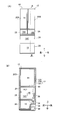
- FIG. 3A is a perspective view showing the door frame 42
- FIG. 3B is a cross-sectional view taken along line BB in FIG. 3A
- FIG. 3C is FIG. 3B. It is sectional drawing which expands and shows the important point of.
- the transparent plate member 40 is also shown together with the door frame 42.
- the door frame 42 has four side surfaces constituting the side surface of the door, specifically, an upper side surface portion 48A, a lower side surface portion 48B, a left side surface portion 48C, and a right side surface portion 48D.
- these four side portions may be collectively referred to as a side portion 48.
- An adhesive surface portion 50 is formed as a flat surface extending inward from the front end portions of the upper side surface portion 48A, the lower side surface portion 48B, the left side surface portion 48C, and the right side surface portion 48D.
- the bonding surface portion 50 is a portion for bonding the transparent plate material 40 made of glass, and has a flat surface corresponding to the peripheral portion of the transparent plate material 40.
- a crosspiece 43 is installed between the left side surface portion 48C and the right side surface portion 48D.
- a plurality of crosspieces 43 are installed at equal intervals in the vertical direction.
- an adhesive surface portion 50 is formed upward from the front end portion of the lower side surface portion 48 ⁇ / b> B of the door frame 42, and the transparent plate member 40 is bonded to the front surface of the adhesive surface portion 50. Yes.
- the transparent plate member 40 is bonded to the bonding surface portion 50 via an adhesive 58.
- only the lower part of the bonding surface portion 50 is bonded to the transparent plate member 40 via the adhesive 58, but the entire bonding surface portion 50 may be bonded to the transparent plate member 40 via the bonding agent 58.
- thermoplastic adhesive is employed as the adhesive 58 used in this embodiment.
- the adhesive 58 of this embodiment exhibits a strong adhesive force as compared with the adhesive tape used in the background art. Therefore, since the area required for bonding the transparent plate member 40 to the door frame 42 can be reduced, the height L1 of the bonding surface portion 50 can be reduced, and the resin material constituting the door frame 42 can be saved. And the weight reduction of the door frame 42 is implement
- the groove portion 52 is formed by recessing the vicinity of the outer peripheral portion of the bonding surface portion 50 into a rectangular shape.
- the groove portion 52 is formed along the upper side surface portion 48A, the lower side surface portion 48B, the left side surface portion 48C, and the right side surface portion 48D shown in FIG.
- the groove portion 52 may be formed continuously along the upper side surface portion 48A, the lower side surface portion 48B, the left side surface portion 48C, and the right side surface portion 48D shown in FIG. 3A, or may be formed discretely.
- the role of the groove 52 is to store the adhesive 58 used for bonding the transparent plate 40.
- the adhesive 58 By storing the adhesive 58 in the groove 52, it is possible to prevent the liquid or semi-solid adhesive 58 from leaking to the outside in the middle of the manufacturing process. Moreover, the effect which the adhesive strength of the adhesive agent 58 and the door frame 42 improves by filling the groove part 52 with the adhesive agent 58 is also anticipated.
- the depth L3 of the groove 52 based on the main surface 50A of the adhesive surface 50 is, for example, not less than 0.5 mm and not more than 1.5 mm. If it is this range, the adhesive agent 58 which moves outside at the process of adhere
- the protruding portion 56 is formed by partially protruding the main surface 50A of the bonding surface portion 50 forward.
- the protrusion 56 is formed adjacent to the groove 52 and has a substantially cylindrical shape protruding forward.
- the protruding portion 56 is discretely, intermittently or continuously formed along the upper side surface portion 48A, the lower side surface portion 48B, the left side surface portion 48C and the right side surface portion 48D shown in FIG.
- the transparent plate member 40 can be stably separated by the protruding portions 56 by providing the protruding portions 56 at least at the four corners of the door frame 42.
- the protruding portions 56 By forming the protruding portions 56 discretely, the flow of the adhesive in the bonding process at the time of manufacturing described below is not hindered by the protruding portions 56. Therefore, as shown in FIG. 3B, the adhesive 58 can be sufficiently spread between the adhesive surface portion 50 of the door frame 42 and the transparent plate member 40. Further, in the bonding process, it is possible to favorably flow the adhesive into the groove 52 shown in FIG.
- the protruding portion 56 By forming the protruding portion 56 on the bonding surface portion 50, the front surface of the protruding portion 56 comes into contact with the rear main surface of the transparent plate member 40. Can be separated accordingly.
- the thickness of the adhesive 58 that bonds the transparent plate member 40 and the bonding surface portion 50 is secured to the same level as the protruding portion 56. Therefore, the thermal expansion coefficient is different between the transparent plate material 40 made of glass and the door frame 42 made of ABS resin, so that even if temperature distortion occurs under the usage conditions, the adhesive 58 deforms the temperature distortion. Can be relaxed. As a result, the transparent plate member 40 and the door frame 42 are prevented from being deformed or damaged due to temperature distortion.
- the protrusion 56 is adjacent to the groove 52, but the groove 52 and the protrusion 56 may be separated from each other.
- the height L2 of the protruding portion 56 with respect to the main surface 50A of the bonding surface portion 50 is, for example, not less than 0.5 mm and not more than 1.5 mm.
- the thickness of the adhesive 58 is also defined in the same range, and the effect of absorbing the above-described temperature strain can be achieved.
- the height L2 of the protrusion 56 is less than 0.5 mm, it is considered that the thickness of the adhesive 58 is not sufficiently ensured and the temperature strain is not sufficiently absorbed by the adhesive 58.
- the height L2 of the protrusion part 56 is longer than 1.5 mm, it is possible that the thickness of the whole door will increase excessively.
- the wall portion 54 is formed by protruding the outer peripheral end portion of the bonding surface portion 50 forward.
- the wall portion 54 is continuously formed along the upper side surface portion 48A, the lower side surface portion 48B, the left side surface portion 48C, and the right side surface portion 48D shown in FIG.
- the cross-sectional shape of the wall portion 54 is such that the front end surface exhibits an inclined surface in consideration of contact with the end portion of the transparent plate member 40.
- the height L4 of the wall portion 54 with respect to the main surface 50A of the bonding surface portion 50 is, for example, not less than 0.5 mm and not more than 1.5 mm.
- the interference with the transparent plate member 40 can be suppressed while preventing the adhesive 58 from flowing out to the outside.
- the height L4 of the wall portion 54 is less than 0.5 mm, the adhesive 58 once stored in the groove portion 52 in the middle of the manufacturing process may flow out to the outside beyond the wall portion 54. There is. If the height L4 of the wall 54 is longer than 1.5 mm, the tip of the wall 54 may interfere with the transparent plate 40 in the process of assembling the transparent plate 40 to the door frame 42.
- the manufacturing method of the refrigerator of this form WHEREIN The process S11 which prepares a door frame etc., the process S12 which applies an adhesive agent to a door frame, and mounts a transparent board
- FIG. 5 shows a manufacturing apparatus such as a belt conveyor used in the manufacturing method of the refrigerator of this embodiment.
- the transparent plate material 40A, the door frame 42A, the door frame 42B, and the transparent plate material 40B are placed on the belt conveyors 60, 62, 64, and 66, respectively.
- the belt conveyors 60, 62, 64 and 66 convey these at a predetermined speed.
- the transparent plate material 40A, the door frame 42A, the door frame 42B, and the transparent plate material 40B are put into positions indicated by P1 on the belt conveyors 60, 62, 64, and 66.
- the belt conveyors 60, 62, 64, and 66 convey each member placed on the upper surface from the left to the right on the paper surface at the same speed. Moreover, the belt conveyor 60 and the belt conveyor 62 are used as a pair in order to manufacture a door. The belt conveyor 64 and the belt conveyor 66 are used as a pair in order to manufacture another door. Thus, by arranging two sets of belt conveyors 60, 62, 64, 66 for manufacturing doors close to each other, a coating device 68, a crimping device 70, and a transfer robot 72 described later can be shared. , Production efficiency can be improved.
- an adhesive is applied to the door frame 42 in step S12. Specifically, first, by rotating the belt conveyors 62 and 64 shown in FIG. 5, the door frames 42A and 42B placed on the upper surfaces thereof are conveyed to a position indicated by P2. As a result, the door frames 42 ⁇ / b> A and 42 ⁇ / b> B placed on the belt conveyors 62 and 64 are disposed below the coating device 68. At the same time, the transparent plate members 40A and 40B placed on the belt conveyors 60 and 66 are also conveyed to the position indicated by P2.
- FIG. 6A is a perspective view showing this step
- FIG. 6B is a cross-sectional perspective view showing the door frame 42 after application is completed.
- door frame 42 has four side surfaces, specifically, upper side surface portion 48A, lower side surface portion 48B, left side surface portion 48C, and right side surface portion 48D, and these side surface portions.
- An adhesive surface portion 50 extends inward from the end portion of each. In this step, the adhesive 58 is applied to the upper surface of the adhesive surface portion 50.
- the adhesive used in this embodiment is a hot melt adhesive, that is, a thermoplastic adhesive, and is heated to about 100 degrees to be in a liquid or semi-solid state, and the adhesive surface portion of the door frame 42 50 is applied.
- the adhesive 58 is continuously applied so as to draw a rectangle on the upper surface of the adhesive surface portion 50 using the nozzle 74 provided in the application device 68 (FIG. 5).
- the adhesive 58 is applied on the main surface 50A of the bonding surface portion 50 so as to be in a bead shape. Further, the adhesive 58 is applied on the inner side of the protrusion 56 on the main surface 50 ⁇ / b> A of the adhesive surface portion 50. By doing in this way, the adhesive agent 58 can be spread over the whole inner part of 50 A of main surfaces in the process after crimping
- one coating device 68 is provided for the door frame 42 ⁇ / b> A placed on the upper surface of the belt conveyor 62 and the door frame 42 ⁇ / b> B placed on the upper surface of the belt conveyor 64. It is possible to perform the coating process all at once. Thereby, there is an advantage that the manufacturing equipment is simplified and the manufacturing cost is reduced.
- step S13 the transparent plate 40 is placed on the upper surface of the door frame 42 to which the adhesive 58 has been applied.
- the transparent plate material 40A, the door frame 42A, the door frame 42B, and the transparent plate material 40B placed on these upper surfaces are changed to P3. Move to the position indicated by.
- the transparent plate 40A placed on the upper surface of the belt conveyor 60 was placed on the upper surface of the belt conveyor 62. It mounts on the upper surface of the door frame 42A.
- the transfer robot 72 performs the transfer operation while adsorbing the upper surface of the transparent plate 40A made of glass.
- the transfer robot 72 places the transparent plate 40 ⁇ / b> B placed on the upper surface of the belt conveyor 66 on the upper surface of the door frame 42 ⁇ / b> B placed on the upper surface of the belt conveyor 64.
- the belt conveyor 62 and the belt conveyor 64 are adjacent to each other, there is an advantage that the above-described transfer operation can be performed collectively by one transfer robot 72 disposed between them.
- the transparent plate 40 is placed so as to close the upper surface of the door frame 42.
- the adhesive 58 is applied in a bead shape along the bonding surface portion 50 of the door frame 42, the entire outer peripheral portion of the transparent plate 40 is bonded to the bonding surface portion 50 of the door frame 42.
- the transparent plate 40 is firmly bonded to the door frame 42.
- the transparent plate 40 is pressure-bonded to the door frame 42 in step S14.
- the door frames 42A and 42B are moved to a point indicated by P4.
- the door frames 42 ⁇ / b> A and 42 ⁇ / b> B are arranged below the crimping device 70.
- Transparent plate members 40A and 40B are placed on the upper surfaces of the door frames 42A and 42B in the previous step.
- a pressing force is evenly applied from above to the transparent plate material 40 placed on the upper surface of the door frame 42.
- the adhesive 58 is pushed by the transparent plate material 40, and the adhesive 58 spreads suitably between the door frame 42 and the transparent plate material 40.
- the transparent plate member 40 is pressed against the door frame 42, and the lower peripheral portion of the transparent plate member 40 comes into contact with the upper surface of the protruding portion 56 of the door frame 42.
- the protruding portion 56 protrudes upward from the main surface 50A of the bonding surface portion 0.5 mm to 1.5 mm. Therefore, the adhesive 58 disposed between the main surface 50A of the adhesive surface portion 50 and the transparent plate member 40 also has the same thickness (0.5 mm to 1.5 mm) as the protruding portion 56. When the adhesive 58 is in such a thickness range, even if temperature distortion occurs between the transparent plate member 40 and the door frame 42 under use conditions, the adhesive 58 that bonds the two deforms. The temperature distortion is relieved.
- the liquid or semi-solid adhesive 58 spreads outside by pressing the transparent plate 40 to the door frame 42.
- the adhesive 58 that is going to move outward is caused to flow into the groove 52.
- the groove 52 is formed sufficiently deep, for example, about 0.5 mm to 1.5 mm. Therefore, the adhesive 58 moving toward the outside is stored in the groove portion 52, and the outflow of the adhesive 58 to the outside is prevented.
- the protrusions 56 are formed discretely, so that the spread of the adhesive 58 is not hindered by the protrusions 56. Therefore, the adhesive 58 can be spread to the outer peripheral end of the transparent plate 40. For the same reason, since the flow of the adhesive 58 flowing into the groove 52 is not hindered by the protrusion 56, the surplus adhesive 58 is stored in the groove 52 and is prevented from flowing out. Yes.
- a wall 54 protruding upward is formed outside the groove 52.
- the height at which the wall portion 54 protrudes upward is about 0.5 mm to 1.5 mm, and is sufficiently high. Therefore, the outflow of the adhesive 58 stored in the groove 52 to the outside is prevented by the presence of the wall 54.
- the door frames 42A and 42B are moved to the position indicated by P5 by rotating the belt conveyors 62 and 64 with reference to FIG. Thereafter, the door frames 42A and 42B are taken out from the belt conveyors 62 and 64.
- the adhesive 58 is cooled and hardened.
- the adhesive 58 used in this embodiment is of a thermoplastic type, but has a property that it completely cures when it absorbs moisture in the air and does not soften even after heating.
- step S16 the inner plate material is incorporated and the heat insulating material is filled.
- an inner plate member 44 is incorporated in the rear main surface of the door frame 42.
- the inner plate member 44 may be assembled by fitting the outer peripheral end portion of the inner plate member 44 to the door frame 42 or bonding the outer peripheral end portion of the inner plate member 44 to the door frame 42.
- a foam heat insulating material 46 such as urethane foam is filled in the internal space surrounded by the door frame 42, the transparent plate material 40 and the inner plate material 44.
- Another member such as a gasket is attached to the door frame 42 to manufacture the door 20A shown in FIG.
- other doors 20B to 20 shown in FIG. 1A are also manufactured by the same manufacturing method.
- the refrigerator 10 is manufactured by attaching these doors 20A to 28 together with other members to the refrigerator main body 12.
Abstract
透明板材と扉枠との接着構造が最適化された扉を備えた冷蔵庫およびその製造方法を提供する。 扉は、額縁形状を呈する扉枠(42)と、扉枠に前面から接着された透明板材(40)と、扉枠に後面から接合された内側板材と、扉枠(42)、透明板材(40)および内側板材で囲まれる空間に充填された発泡断熱材と、を有する。更に、扉枠(42)は、扉の側面を構成する各側面部と、透明板材(40)が接着される接着面部(50)と、を有し、透明板材(40)は、接着剤(58)を介して、扉枠(42)の接着面部(50)に接着される。また、扉枠(42)の接着面部(50)の外周部付近を窪ませて溝部(52)が形成されている。
Description
本発明は冷蔵庫およびその製造方法に関し、特に、前面がガラス板等の透明板材により覆われる扉を備えた冷蔵庫およびその製造方法に関する。
一般的な冷蔵庫は、冷蔵庫本体に複数の貯蔵室が設けられており、上方から冷蔵室、冷凍室、野菜室が順次配置されている。また、冷蔵室、冷凍室および野菜室の前面開口は、断熱構造を有する扉により閉鎖されている。
一般的に、このような扉は、扉枠の前面が前面板により塞がれ、扉枠の後面が後面板により塞がれている。そして、扉枠、前面板および後面板により囲まれる空間には発泡ウレタン等の発泡断熱材が充填されている。
また、近年、冷蔵庫前面の外観性を向上させるために、前面がガラス板から構成された扉を有する冷蔵庫が登場してきている。このような構成を有する冷蔵庫の扉の構成が以下の特許文献に記載されている。
特許文献1では、ガラス板から成る扉前板を備えた扉を有する冷蔵庫が開示されている。具体的には、この文献の図1およびその説明箇所を参照すると、扉外枠9の前面はガラスからなる扉前板8により覆われ、扉外枠9の後面は扉後板14により覆われている。そして、扉外枠9、扉前板8および扉外枠9により囲まれる内部空間には真空断熱パネル10が配置されている。また、図3およびその説明箇所を参照すると、前板8の周辺部は両面粘着テープ17を介して扉外枠9に接着されている。
特許文献2を参照すると、前面がガラス板から構成される扉を有する冷蔵庫が開示されている。具体的には、この文献の図8を参照すると、縁枠24の前面を透明前板25で塞ぎ、縁枠24の後面を内箱フレーム23で塞いでいる。また、縁枠24、透明前板25および内箱フレーム23で囲まれる内部空間には発泡ウレタン29が充填されている。更に、透明前板25の周辺部は、両面テープ30を介して、縁枠24の前面に接着されている。
特許文献3では、この文献の各図面を参照すると、扉枠12の前面をガラス11aで塞ぎ、扉枠12の後面を扉内板14で塞ぎ、これらにより囲まれる内部空間に発泡断熱材15を充填している。また、ガラス11aの外周端部は、内側から貼着される外板固定用テープ13にて、扉枠12に固定されている。
しかしながら、特許文献1、特許文献2および特許文献3に開示された発明では、前面に配置されたガラス板を、両面テープを介して扉枠に接着していた。一般に、両面テープの接着力は必ずしも大きくないので、ガラス板を扉枠に強固に接着させるためには、接着される扉枠側にて広い接着面積が必要となり、これにより扉枠のサイズが多くなることが扉自体の軽量化・小型化を阻んでいた。
更に、冷蔵庫の扉の製造工程を考慮すると、両面テープでガラス板を扉枠に貼着することは、作業員が手作業で行う必要があり、製造用機械で両面テープの貼着を行うことが容易でない。よって、ガラス板の接着に両面テープを採用することにより、製造工程の自動化が阻害される課題が有った。
本発明は上記の問題点を鑑みて成され、本発明の目的は、透明板材と扉枠との接着構造が最適化された扉を備えた冷蔵庫およびその製造方法を提供することに成る。
本発明の冷蔵庫は、前面に開口が形成された冷蔵庫本体と、前記開口を閉鎖する扉と、を備え、前記扉は、額縁形状を呈する扉枠と、前記扉枠に前面から接着された透明板材と、前記扉枠に後面から接合された内側板材と、前記扉枠、前記透明板材および前記内側板材で囲まれる空間に充填された発泡断熱材と、を有し、前記扉枠は、前記扉の側面を構成する側面部と、前記透明板材が接着される接着面部と、を有し、前記透明板材は、接着剤を介して、前記扉枠の前記接着面部に接着され、前記扉枠の前記接着面部の外周部付近を窪ませて溝部を設けることを特徴とする。
更に、本発明の冷蔵庫は、前記溝部は、前記接着面部の側辺に沿って連続して形成されることを特徴とする。
更に、本発明の冷蔵庫は、前記透明板材と重なりあう領域の前記接着面部を部分的に厚み方向に突出させて突出部を設けることを特徴とする。
更に、本発明の冷蔵庫は、前記突出部は、前記接着面部の側辺に沿って離散的に形成されることを特徴とする。
更に、本発明の冷蔵庫は、前記接着剤の厚みは、0.5mm以上1.5mm以下であることを特徴とする。
本発明は、冷蔵庫本体の前面開口を塞ぐ扉を備えた冷蔵庫の製造方法であり、額縁形状を呈し、前記扉の外周側面を構成する側面部と、前記側面部と連続する接着面部とを有する扉枠を用意する工程と、前記扉枠の前記接着面部に接着剤を塗布する工程と、前記扉枠の上面に透明板材を載置する工程と、前記透明板材を前記扉枠に圧着する工程と、前記扉枠に後方から内側板材を組み込み、前記扉枠、前記透明板材および前記内側板材で囲まれる空間に発泡断熱材を充填する工程と、を備え、前記圧着する工程では、前記透明板材を前記扉枠に押圧することで、前記扉枠の前記接着面部と前記透明板材との間で外側に移動する前記接着剤を、前記扉枠を窪ませた溝部に流入させることを特徴とする。
更に、本発明の冷蔵庫の製造方法は、前記圧着する工程では、前記透明板材と重なりあう領域の前記接着面部を部分的に厚み方向に突出させた突出部に、前記透明板材が当接するまで、前記透明板材を押圧することを特徴とする。
本発明の冷蔵庫によれば、前面に開口が形成された冷蔵庫本体と、前記開口を閉鎖する扉と、を備え、前記扉は、額縁形状を呈する扉枠と、前記扉枠に前面から接着された透明板材と、前記扉枠に後面から接合された内側板材と、前記扉枠、前記透明板材および前記内側板材で囲まれる空間に充填された発泡断熱材と、を有し、前記扉枠は、前記扉の側面を構成する側面部と、前記透明板材が接着される接着面部と、を有し、前記透明板材は、接着剤を介して、前記扉枠の前記接着面部に接着され、前記扉枠の前記接着面部の外周部付近を窪ませて溝部を設けている。よって、扉枠の周辺部に溝部を形成することで、透明板材を扉枠に接着させる接着剤の剰余分が溝部に流れ込むので、この剰余分の接着剤が扉枠から外部に流出することが防止される。更に、接着力が大きい接着剤で透明板材を扉枠に貼着することにより、扉枠の接着面部の面積を小さくし、扉枠の材料費を安くすることが出来る。
更に、本発明の冷蔵庫によれば、前記溝部は、前記接着面部の側辺に沿って連続して形成されている。溝部が連続して形成されることにより、剰余の接着剤を貯留して漏出を防止する効果が大きくなる。
更に、本発明の冷蔵庫によれば、前記透明板材と重なりあう領域の前記接着面部を部分的に厚み方向に突出させて突出部を設けている。突出部が透明板材に当接することで、接着剤の厚みが所定以上に確保され、使用状況下の温度変化に伴う歪を接着剤で吸収できる。
更に、本発明の冷蔵庫によれば、前記突出部は、前記接着面部の側辺に沿って離散的に形成されている。よって、製造時に於いて、液状または半固形状である接着剤の流動が突出部により阻害されず、扉枠と透明部材との間に接着剤を充分に行き渡らせることができる。
更に、本発明の冷蔵庫によれば、前記接着剤の厚みは、0.5mm以上1.5mm以下である。従って、ガラス板と扉枠との熱膨張係数の差異による温度歪が、接着剤が変形することで吸収される。
本発明によれば、冷蔵庫本体の前面開口を塞ぐ扉を備えた冷蔵庫の製造方法であり、額縁形状を呈し、前記扉の外周側面を構成する側面部と、前記側面部と連続する接着面部とを有する扉枠を用意する工程と、前記扉枠の前記接着面部に接着剤を塗布する工程と、前記扉枠の上面に透明板材を載置する工程と、前記透明板材を前記扉枠に圧着する工程と、前記扉枠に後方から内側板材を組み込み、前記扉枠、前記透明板材および前記内側板材で囲まれる空間に発泡断熱材を充填する工程と、を備え、前記圧着する工程では、前記透明板材を前記扉枠に押圧することで、前記扉枠の前記接着面部と前記透明板材との間で外側に移動する前記接着剤を、前記扉枠を窪ませた溝部に流入させている。よって、圧着する工程にて外側に向かって移動する接着剤を溝部に流入させることで、接着剤の外部への流出が防止される。
更に、本発明の冷蔵庫の製造方法によれば、前記圧着する工程では、前記透明板材と重なりあう領域の前記接着面部を部分的に厚み方向に突出させた突出部に、前記透明板材が当接するまで、前記透明板材を押圧する。よって、突出部に透明板材が当接するまで透明板材を圧着することで、接着剤の厚みを所定の範囲にすることが可能となる。
以下、図を参照して本発明の実施の形態にかかる冷蔵庫10を説明する。
図1を参照して、冷蔵庫10の概略的構成を説明する。図1(A)は冷蔵庫10を全体的に示す正面図であり、図1(B)は図1(A)のB-B線で冷蔵庫10を切断した場合の断面図である。
本形態では、上下前後左右の各方向を適宜用いて冷蔵庫10の構成等を説明する。ここで、左右方向とは、冷蔵庫10を正面から見た場合の方向を示している。
図1(A)に示すように、本実施形態に係る冷蔵庫10は、断熱箱体である冷蔵庫本体12を備え、この冷蔵庫本体12の内部に食品等を貯蔵する貯蔵室が形成されている。この貯蔵室として、上方から、冷蔵室14、製氷室16Aおよび上段冷凍室16B、下段冷凍室16C並びに野菜室18が形成されている。ここで、製氷室16A、上段冷凍室16Bおよび下段冷凍室16Cは、1つの貯蔵庫を区切ることで形成されており、以下の説明では、これらを冷凍室16と総称することもある。
冷蔵庫10の基本的な機能は、各貯蔵室に収納された食品等の被貯蔵物を所定の温度に冷却することにある。一例として、冷蔵室14の庫内温度は冷蔵温度域であり、冷凍室16の庫内温度は冷凍温度域であり、野菜室18の庫内温度は冷蔵温度域である。
冷蔵庫本体12の前面は開口しており、各貯蔵室の開口部には、各々扉が開閉自在に設けられている。冷蔵室14の左側部分を塞ぐ扉20Aは、左側上下端部が冷蔵庫本体12に回転自在に支持されており、冷蔵室14の右側部分を塞ぐ扉20Bは、右側上下端部が冷蔵庫本体12に回転自在に支持されている。また、製氷室16A、上段冷凍室16B、下段冷凍室16Cおよび野菜室18は、夫々、引き出し自在な扉22、24、26および28で塞がれている。
図1(B)を参照して、冷蔵庫10の冷蔵庫本体12は、前面に開口部を有する鋼板製の外箱12Aと、外箱12Aの内側に間隙を持たせて配設されて前面に開口部を有する合成樹脂製の内箱12Bと、外箱12Aと内箱12Bとの間隙に充填発泡された発泡ポリウレタン製の断熱材12Cと、から構成されている。
冷蔵庫本体12の前面開口を塞ぐ各扉20A~28は、冷蔵庫本体12と同様の断熱構造を採用している。また、図1(B)に示すように、冷蔵室14と冷凍室16との間に断熱仕切壁30が配置されており、冷凍室16と野菜室18との間にも断熱仕切壁32が配置されている。これらの断熱仕切壁30、32も、冷蔵庫本体12と同様の断熱構造を採用している。
下段冷凍室16Cの後方に形成された冷却室の内部には、上記した各貯蔵室を循環する空気を冷却するための蒸発器である冷却器38が配置されている。また、冷蔵庫本体12の野菜室18の後方に区画形成された機械室34には圧縮機36が配置されている。冷却器38は、圧縮機36、図示しない放熱器、図示しないキャピラリーチューブまたは膨張弁と冷媒配管を介して接続されており、蒸気圧縮式の冷凍サイクル回路を構成している。
本形態では、上記した扉20A~28の前面は、意匠性を向上させるために、ガラスから成る透明板材から構成されている。
図2を参照して、上記した冷蔵庫10が備える扉20Aの構成を説明する。図2(A)は扉20Aを前後方向に分解した状態を示す斜視図であり、図2(B)は扉20Aの下部断面図である。
図2(A)を参照して、扉20Aは、略額縁形状を呈する扉枠42と、扉枠42の前面に接着されたガラスから成る透明板材40と、扉枠42に後面から接合されたパネルとしての内側板材44と、を有している。また、扉枠42、透明板材40および内側板材44で囲まれる内部空間には、扉20Aに断熱性を持たせるために、図2(B)に示すような発泡断熱材46が充填されている。このような断熱構造は、図1(A)に示す他の扉20B~28に関しても同様である。
透明板材40は、正面視で矩形の形状を呈するガラス製の板材であり、所定の着色加工が施されている。この着色加工としては、透明なガラス板の後面が塗装されたものでも良く、有色ガラスによる着色でも良い。上記したように本形態では、扉20Aの前面に着色ガラスから成る透明板材40を配することにより意匠性を向上させ、更には扉20A全体の機械的強度を向上させている。透明板材40は、後述するように接着剤を介して扉枠42に接着される。
扉枠42は、正面視で略額縁形状を呈する枠部材であり、扉20Aの側面部分を構成すると共に、扉20Aを構成する他の部品である透明板材40、内側板材44および発泡断熱材46を支持する役割を有する。扉枠42は、射出成形により一体に成形されたABS樹脂から成る。扉枠42の前面には、上記した透明板材40を接着するための平坦面が形成されている。また、扉枠42の後面は、内側板材44の接着や接合を容易とする形状となっている。扉枠42の形状は、図3を参照して後述する。
内側板材44は、正面視で矩形の形状を呈する板状部材であり、扉枠42を後方から塞ぐ役割を有する。内側板材44は、扉枠42と同様に、一体に成形されたABS樹脂から成る。内側板材44には、扉20Aの後側側面にペットボトル等の被貯蔵物を格納するために、部分的に突起部が形成されている。
発泡断熱材46は、上記した扉枠42、透明板材40および内側板材44により囲まれる内部空間に充填され、扉20Aが塞ぐ冷蔵室14(図1(A))を外部から断熱する機能を有する。発泡断熱材46の材料としては、例えば発泡ウレタンが採用される。
扉20Aの概略的構成は上記の通りであるが、具現化された扉20Aは、上記した各部材の他にも、扉20Aの後面周辺部に設けられるガスケット、扉20Aを冷蔵庫本体に密着させるための磁石、等を備えている。
図3を参照して、上記した扉20Aに含まれる扉枠42の構成を詳述する。図3(A)は扉枠42を示す斜視図であり、図3(B)は図3(A)のB-B線での断面図であり、図3(C)は図3(B)の要所を拡大して示す断面図である。図3(B)では、扉枠42と共に透明板材40も示している。
図3(A)を参照して、扉枠42は、扉の側面を構成する4つの側面部、具体的には上側面部48A、下側面部48B、左側面部48Cおよび右側面部48Dを有する。以下の説明では、これらの4つの側面部を側面部48と総称する場合もある。
上側面部48A、下側面部48B、左側面部48Cおよび右側面部48Dの前方端部から、内側に伸びる平坦面として接着面部50が形成されている。接着面部50は、ガラスから成る透明板材40を接着するための部位であり、透明板材40の周辺部に対応した平坦面を呈している。
左側面部48Cと右側面部48Dとの間には桟材43が架設されている。ここでは、桟材43は上下方向に等間隔に複数個が架設されている。このように、扉枠42の内部に桟材43を形成することにより、扉枠42の機械的強度を向上させることが出来る。
図3(B)を参照して、扉枠42の下側面部48Bの前方端部から上方に向かって接着面部50が形成されており、この接着面部50の前面に透明板材40が接着されている。透明板材40は、接着剤58を介して、接着面部50に接着されている。この図では、接着面部50の下方部分のみが接着剤58を介して透明板材40に接着されているが、接着面部50の全体が接着剤58を介して透明板材40に接着されても良い。
本形態で用いる接着剤58は、例えば熱可塑性接着剤が採用される。本形態の接着剤58は、背景技術で用いられていた接着用テープと比較すると強い接着力を発揮する。よって、透明板材40を扉枠42に接着させる為に必要とされる面積が狭くて済むため、接着面部50の高さL1を低くすることが可能となり、扉枠42を構成する樹脂材料の節約および、扉枠42の軽量化が実現される。
図3(C)を参照して、扉枠42の角部に於ける構成を詳述する。扉枠42では、接着面部50の外周部付近を矩形に窪ませることにより溝部52を形成している。この溝部52は、図3(A)に示した上側面部48A、下側面部48B、左側面部48Cおよび右側面部48Dに沿って形成されている。溝部52は、図3(A)に示す、上側面部48A、下側面部48B、左側面部48Cおよび右側面部48Dに沿って連続して形成されても良いし、離散的に形成されても良い。溝部52の役割は、透明板材40の接着に用いられる接着剤58を貯留することにある。溝部52に接着剤58が貯留されることで、製造工程の途中段階では液状または半固形状である接着剤58が外部に漏出することが防止される。また、溝部52に接着剤58が充填されることで、接着剤58と扉枠42との接着強度が向上する効果も期待される。
接着面部50の主面50Aを基準とした溝部52の深さL3は、例えば、0.5mm以上1.5mm以下である。この範囲であれば、透明板材40を扉枠42に接着する工程にて外部に向かって移動する接着剤58を溝部52に貯留させ、接着剤58が外部に漏出することを防止できる。一方、溝部52の深さL3が0.5mm未満であると、製造工程の途中段階に於いて接着剤58が充分に貯留されずに外部に漏出してしまう恐れがある。また、溝部52の深さL3が1.5mmよりも深いと、射出成形によりこのような深い溝部52を形成することが容易でない恐れがある。
突出部56は、接着面部50の主面50Aを部分的に前方に突出させて形成されている。突出部56は、溝部52に隣接して形成されており、前方に突出する略円柱形状を呈している。突出部56は、図3(A)に示す上側面部48A、下側面部48B、左側面部48Cおよび右側面部48Dに沿って、離散的若しくは断続的または連続的に形成されている。突出部56が離散的に形成される場合は、少なくとも、扉枠42の四隅に突出部56を設けることで、突出部56で透明板材40を安定して離間させることが出来る。
突出部56を離散的に形成することにより、下記する製造時の接着工程における接着剤の流動が、突出部56により阻害されないように成る。よって、図3(B)に示すように、扉枠42の接着面部50と透明板材40との間に、十分に接着剤58を行き渡らせることができる。また、接着工程において、図3(C)に示す溝部52に接着剤を良好に流入させることが可能となる。
接着面部50に突出部56を形成することにより、突出部56の前面が透明板材40の後側主面に接触するので、主面50Aと透明板材40とを、突出部56の高さL2に応じて離間させることが出来る。換言すると、透明板材40と接着面部50とを接着する接着剤58の厚みが、突出部56と同程度に確保される。従って、ガラスから成る透明板材40とABS樹脂から成る扉枠42とで熱膨張係数が異なることにより、使用状況下で温度歪が発生しても、この温度歪を接着剤58が変形することで緩和できる。結果的に、温度歪みにより透明板材40や扉枠42が変形、破損してしまうことが防止される。ここで、図3(C)では、突出部56は溝部52に隣接されているが、溝部52と突出部56は離間してもよい。
接着面部50の主面50Aを基準とした突出部56の高さL2は、例えば0.5mm以上1.5mm以下である。突出部56の高さL2をこのような範囲とすることにより、接着剤58の厚みも同様な範囲に規定され、上記した温度歪を吸収する効果を奏することができる。一方、突出部56の高さL2が0.5mm未満であると、上記した接着剤58の厚みが充分に確保されず、温度歪が接着剤58により充分には吸収されないと考えられる。また、突出部56の高さL2が1.5mmよりも長いと、扉全体の厚みが過分に増加してしまうことが考えられる。
壁部54は、接着面部50の外周端部を前方に突出させて形成されている。壁部54は、図3(A)に示す上側面部48A、下側面部48B、左側面部48Cおよび右側面部48Dに沿って、連続して形成される。壁部54の断面形状は、透明板材40の端部との接触を考慮して、前方端面が傾斜面を呈する形状となっている。このような壁部54を形成することにより、製造工程の途中段階にて溝部52に流入した液状の接着剤58が外部に流出することが抑制される。接着面部50の主面50Aを基準とした壁部54の高さL4は、例えば0.5mm以上1.5mm以下である。壁部54の高さL4をこのような範囲にすることにより、接着剤58の外部への流出を防止しつつ、透明板材40との干渉を抑制することが出来る。ここで、壁部54の高さL4が0.5mm未満であると、製造工程の途中段階にて溝部52に一旦貯留された接着剤58が壁部54を超えて外部に流出してしまう恐れがある。また、壁部54の高さL4が1.5mmよりも長いと、扉枠42に透明板材40を組み付ける工程にて、壁部54の先端部が透明板材40に干渉してしまう恐れがある。
図4以降の図面を参照して、上記した冷蔵庫10の製造方法を説明する。
図4に示すフローチャートを参照して、本形態の冷蔵庫の製造方法は、扉枠等を用意する工程S11と、扉枠に接着剤を塗布する工程S12と、扉枠に透明板材を載置する工程S13と、扉枠に透明部材を圧着する工程S14と、扉枠に内側板材を組込み、断熱材を充填する工程S15と、を有している。各工程を以下に詳述する。
先ず、工程S11では、扉を構成する扉枠42等を用意する。図5は、本形態の冷蔵庫の製造方法で用いられる、ベルトコンベア等の製造装置を示している。本形態では、冷蔵庫の扉を製造する際に、ベルトコンベア60、62、64および66に、夫々、透明板材40A、扉枠42A、扉枠42Bおよび透明板材40Bを載置している。ベルトコンベア60、62、64および66は、これらを所定速度で搬送する。透明板材40A、扉枠42A、扉枠42Bおよび透明板材40Bは、ベルトコンベア60、62、64、66のP1で示す位置に投入される。
ベルトコンベア60、62、64、66は、互いに同じ早さで、上面に載置された各部材を、紙面上にて左方から右方に搬送している。また、ベルトコンベア60およびベルトコンベア62は、扉を製造するために一対として用いられる。ベルトコンベア64とベルトコンベア66とは、他の扉を製造するために一対として用いられる。このように、扉を製造する二組のベルトコンベア60、62、64、66を接近して配置することにより、後に説明する塗布装置68、圧着装置70および移載ロボット72を共用することができ、生産効率を向上させることができる。
次に、工程S12では扉枠42に接着剤を塗布する。具体的には、先ず、図5に示すベルトコンベア62、64を回転させることにより、これらの上面に載置された扉枠42A、42Bを、P2で示す位置まで搬送する。これにより、ベルトコンベア62、64に載置された扉枠42A、42Bは、塗布装置68の下方に配置されることになる。同時に、ベルトコンベア60、66に載置された透明板材40A、40Bも、P2で示す位置まで搬送される。
図6を参照して、上記した塗布装置68を用いて扉枠42に接着剤を塗布する方法を説明する。図6(A)は本工程を示す斜視図であり、図6(B)は塗布が終了した後の扉枠42を示す断面斜視図である。
図6(A)を参照して、扉枠42は4つの側面部、具体的には上側面部48A、下側面部48B、左側面部48Cおよび右側面部48Dを有しており、これらの側面部の端部から内側に接着面部50が延在している。本工程では、接着面部50の上面に接着剤58を塗布している。
本形態で使用される接着剤は、ホットメルト型接着剤、即ち熱可塑性接着剤であり、100度程度に加熱されることで液状または半固形状とされた状態で、扉枠42の接着面部50に塗布されている。本形態では、塗布装置68(図5)が備えるノズル74を用いて、接着面部50の上面に矩形を描くように、接着剤58を連続的して塗布している。
図6(B)を参照して、接着剤58は、接着面部50の主面50Aにて、ビード状となるように塗布されている。また、接着剤58は、接着面部50の主面50Aに於いて、突出部56よりも内側に塗布されている。このようにすることで、圧着を行う後の工程にて接着剤58を主面50Aの内側部分の全域に行き渡らせることができる。
また、図5に示すように、本形態では、ベルトコンベア62の上面に載置された扉枠42Aと、ベルトコンベア64の上面に載置された扉枠42Bに対して、1つの塗布装置68で一括して塗布工程を行うことが可能である。これにより、製造設備が簡素化されて製造コストが低減する利点がある。
背景技術で述べた接着テープを用いた接着方法であると、テープ貼着工程等を製造機械で自動化することが容易ではなく、作業員による手作業で貼り付け作業を行う必要があった。それに対して、本形態では、扉を構成する透明板材40を接着するために、液状または半固形状態で塗布される接着剤58を用いるので、上記した塗布装置68を用いて接着工程を自動化することが可能となる。
上記工程が終了した後は、工程S13で、接着剤58が塗布された扉枠42の上面に、透明板材40を載置する。先ず、図5を参照して、ベルトコンベア60、62、64、66を回転させることにより、これらの上面に載置された透明板材40A、扉枠42A、扉枠42Bおよび透明板材40Bを、P3で示す位置まで移動させる。
次に、ベルトコンベア62とベルトコンベア64との間に配置された移載ロボット72を用いて、ベルトコンベア60の上面に載置された透明板材40Aを、ベルトコンベア62の上面に載置された扉枠42Aの上面に載置する。移載ロボット72は、ガラスから成る透明板材40Aの上面を吸着した状態で移送作業を行う。同様に、移載ロボット72により、ベルトコンベア66の上面に載置された透明板材40Bを、ベルトコンベア64の上面に載置された扉枠42Bの上面に載置する。本工程では、ベルトコンベア62とベルトコンベア64とが隣接しているので、両者の間に配置された1つの移載ロボット72で、上記の移載作業を一括して行える利点がる。
図7(A)に示すように、本工程では、扉枠42の上面を塞ぐように透明板材40が載置される。前工程にて、扉枠42の接着面部50に沿ってビード状に接着剤58が塗布されているので、透明板材40の外周部全域が扉枠42の接着面部50に接着され、結果的に透明板材40は扉枠42に強固に接着される。
図7(B)を参照して、扉枠42の上面に透明板材40を載置すると、透明板材40の下面周辺部が、液状または半固形状の接着剤58の上面に接触する。本工程では、接着剤58に対しては、透明板材40の重量が作用するのみである。よって、接着剤58は、扉枠42の接着面部50と透明板材40との間で、充分に広がっていない。また、透明板材40の下面は、扉枠42の突出部56の上面に当接していない。
上記工程が終了した後は、工程S14で、扉枠42に透明板材40を圧着させる。
先ず、図5を参照して、ベルトコンベア62、64を回転させることで、扉枠42A、42Bを、P4で示す地点まで動作させる。これにより、圧着装置70の下方に扉枠42A、42Bが配置される。扉枠42A、42Bの各々の上面には、前工程にて透明板材40A、40Bが載置されている。
本工程でも、ベルトコンベア62とベルトコンベア64とが隣接されているので、一台の圧着装置70で、扉枠42A、42Bに対して一括して下記する圧着工程を行える利点がある。
図8(A)を参照して、本工程では、扉枠42の上面に載置された透明板材40に対して上方から均等に押圧力を加えている。このようにすることで、接着剤58が透明板材40により押され、扉枠42と透明板材40との間で、接着剤58が好適に広がる。同時に、図8(B)に示すように、透明板材40が扉枠42に対して押し付けられ、透明板材40の下面周辺部が、扉枠42の突出部56の上面に当接する。
図3(C)を参照して説明したように、突出部56は、接着面部50の主面50Aから上方に0.5mm~1.5mm突出している。よって、接着面部50の主面50Aと透明板材40との間に配置される接着剤58も、突出部56と同様の厚さ(0.5mm~1.5mm)となる。接着剤58がこのような厚みの範囲となることで、使用状況下にて透明板材40と扉枠42との間に温度歪が発生したとしても、両者を接着させる接着剤58が変形することで温度歪が緩和される。
更に本工程では、透明板材40を扉枠42に圧着させることで、液状または半固形状の接着剤58は、外側にも広がる。
本形態では、外側に移動しようとする接着剤58を溝部52に流入させている。図3(C)を参照して上記したように、溝部52は例えば0.5mm~1.5mm程度と充分に深く形成されている。よって、外側に向かって移動する接着剤58は、溝部52に貯留され、接着剤58の外部への流出は防止されている。更に本形態では、図3(A)を参照して上記したように、突出部56を離散的に形成しているので、接着剤58の広がりが突出部56により阻害されることはない。よって、透明板材40の外周端部に至るまで、接着剤58を行き渡らせることができる。同様の理由により、溝部52に流入する接着剤58の流れが突出部56により阻害されることがないので、剰余の接着剤58は、溝部52に貯留され、外部に流出することは抑止されている。
更に、溝部52の外側に、上方に突出する壁部54を形成している。上記したように壁部54が上方に突出する高さは0.5mm~1.5mm程度であり充分に高く形成されている。よって、溝部52に貯留された接着剤58の外部への流出は壁部54があることで防止されている。
上記の圧着が終了した後は、図5を参照して、ベルトコンベア62、64を回転させることで、扉枠42A、42Bを、P5で示す位置まで移動させる。その後、ベルトコンベア62、64から扉枠42A、42Bを取り出す。
本工程が終了して所定時間が経過すると接着剤58は冷却されて硬化する。本形態で用いられる接着剤58は熱可塑性型のものであるが、空気中の水分を吸収すると完全硬化し、その後は加熱しても軟化しない性質を有する。
上記工程が終了した後は、工程S16で、内側板材を組込み、断熱材を充填する。具体的には、図2(B)に示すように、扉枠42の後方主面に内側板材44を組み込む。内側板材44の組込みは、内側板材44の外周端部を扉枠42に対して嵌合させても良いし、内側板材44の外周端部を扉枠42に接着してもよい。更に、扉枠42、透明板材40および内側板材44で囲まれる内部空間に、例えば、発泡ウレタン等の発泡断熱材46を充填する。
上記工程が終了した後は、ガスケット等の他の部材を扉枠42に対して取り付けることにより図2に示す扉20Aが製造される。また、同様の製造方法により、図1(A)に示す他の扉20B~28も製造される。これらの扉20A~28を、他の部材と共に、冷蔵庫本体12に取り付けることにより冷蔵庫10が製造される。
以上、本発明の実施形態について説明したが、本発明は、これに限定されるものではなく、本発明の要旨を逸脱しない範囲で、種々の変更が可能である。
10 冷蔵庫
12 冷蔵庫本体
12A 外箱
12B 内箱
12C 断熱材
14 冷蔵室
16 冷凍室
16A 製氷室
16B 上段冷凍室
16C 下段冷凍室
18 野菜室
20、20A、20B 扉
22 扉
24 扉
26 扉
28 扉
30 断熱仕切壁
32 断熱仕切壁
34 機械室
36 圧縮機
38 冷却器
40、40A、40B 透明板材
42、42A、42B 扉枠
43 桟材
44 内側板材
46 発泡断熱材
48 側面部
48A 上側面部
48B 下側面部
48C 左側面部
48D 右側面部
50 接着面部
50A 主面
52 溝部
54 壁部
56 突出部
58 接着剤
60 ベルトコンベア
62 ベルトコンベア
64 ベルトコンベア
66 ベルトコンベア
68 塗布装置
70 圧着装置
72 移載ロボット
74 ノズル
Claims (7)
- 前面に開口が形成された冷蔵庫本体と、前記開口を閉鎖する扉と、を備え、
前記扉は、額縁形状を呈する扉枠と、前記扉枠に前面から接着された透明板材と、前記扉枠に後面から接合された内側板材と、前記扉枠、前記透明板材および前記内側板材で囲まれる空間に充填された発泡断熱材と、を有し、
前記扉枠は、前記扉の側面を構成する側面部と、前記透明板材が接着される接着面部と、を有し、
前記透明板材は、接着剤を介して、前記扉枠の前記接着面部に接着され、
前記扉枠の前記接着面部の外周部付近を窪ませて溝部を設けることを特徴とする冷蔵庫。 - 前記溝部は、前記接着面部の側辺に沿って連続して形成されることを特徴とする請求項1に記載の冷蔵庫。
- 前記透明板材と重なりあう領域の前記接着面部を、部分的に厚み方向に突出させて、突出部を設けることを特徴とする請求項1または請求項2に記載の冷蔵庫。
- 前記突出部は、前記接着面部の側辺に沿って離散的に形成されることを特徴とする請求項3に記載の冷蔵庫。
- 前記接着剤の厚みは、0.5mm以上1.5mm以下であることを特徴とする請求項1から請求項4の何れかに記載の冷蔵庫。
- 冷蔵庫本体の前面開口を塞ぐ扉を備えた冷蔵庫の製造方法であり、
額縁形状を呈し、前記扉の外周側面を構成する側面部と、前記側面部と連続する接着面部とを有する扉枠を用意する工程と、
前記扉枠の前記接着面部に接着剤を塗布する工程と、
前記扉枠の上面に透明板材を載置する工程と、
前記透明板材を前記扉枠に圧着する工程と、
前記扉枠に後方から内側板材を組み込み、前記扉枠、前記透明板材および前記内側板材で囲まれる空間に発泡断熱材を充填する工程と、を備え、
前記圧着する工程では、前記透明板材を前記扉枠に押圧することで、前記扉枠の前記接着面部と前記透明板材との間で外側に移動する前記接着剤を、前記扉枠を窪ませた溝部に流入させることを特徴とする冷蔵庫の製造方法。 - 前記圧着する工程では、前記透明板材と重なりあう領域の前記接着面部を部分的に厚み方向に突出させた突出部に、前記透明板材が当接するまで、前記透明板材を押圧することを特徴とする請求項6に記載の冷蔵庫の製造方法。
Priority Applications (1)
| Application Number | Priority Date | Filing Date | Title |
|---|---|---|---|
| CN201680009317.9A CN107850370A (zh) | 2015-03-03 | 2016-03-03 | 冰箱及其制造方法 |
Applications Claiming Priority (2)
| Application Number | Priority Date | Filing Date | Title |
|---|---|---|---|
| JP2015040906A JP6469480B2 (ja) | 2015-03-03 | 2015-03-03 | 冷蔵庫およびその製造方法 |
| JP2015-040906 | 2015-03-03 |
Publications (1)
| Publication Number | Publication Date |
|---|---|
| WO2016140324A1 true WO2016140324A1 (ja) | 2016-09-09 |
Family
ID=56844817
Family Applications (1)
| Application Number | Title | Priority Date | Filing Date |
|---|---|---|---|
| PCT/JP2016/056658 WO2016140324A1 (ja) | 2015-03-03 | 2016-03-03 | 冷蔵庫およびその製造方法 |
Country Status (3)
| Country | Link |
|---|---|
| JP (1) | JP6469480B2 (ja) |
| CN (1) | CN107850370A (ja) |
| WO (1) | WO2016140324A1 (ja) |
Cited By (2)
| Publication number | Priority date | Publication date | Assignee | Title |
|---|---|---|---|---|
| TWI682139B (zh) * | 2018-03-13 | 2020-01-11 | 日商三菱電機股份有限公司 | 冰箱及該冰箱的製造方法 |
| WO2022208787A1 (ja) * | 2021-03-31 | 2022-10-06 | 三菱電機株式会社 | 冷蔵庫 |
Families Citing this family (10)
| Publication number | Priority date | Publication date | Assignee | Title |
|---|---|---|---|---|
| JP2019132507A (ja) * | 2018-01-31 | 2019-08-08 | 日立グローバルライフソリューションズ株式会社 | 冷蔵庫 |
| JP2019138536A (ja) * | 2018-02-09 | 2019-08-22 | 日立グローバルライフソリューションズ株式会社 | 冷蔵庫 |
| CN109708379B (zh) * | 2017-10-26 | 2020-10-30 | 日立环球生活方案株式会社 | 冰箱 |
| JP6707066B2 (ja) * | 2017-10-26 | 2020-06-10 | 日立グローバルライフソリューションズ株式会社 | 冷蔵庫 |
| JP2019138533A (ja) * | 2018-02-09 | 2019-08-22 | 日立グローバルライフソリューションズ株式会社 | 冷蔵庫 |
| JP7177903B2 (ja) * | 2018-02-09 | 2022-11-24 | 日立グローバルライフソリューションズ株式会社 | 冷蔵庫 |
| JP2019196856A (ja) * | 2018-05-09 | 2019-11-14 | 日立グローバルライフソリューションズ株式会社 | 冷蔵庫 |
| JP7129922B2 (ja) * | 2019-01-23 | 2022-09-02 | 日立グローバルライフソリューションズ株式会社 | 冷蔵庫 |
| JP7261758B2 (ja) * | 2020-02-28 | 2023-04-20 | 日立グローバルライフソリューションズ株式会社 | 扉及びこの製造方法並びに扉を備えた冷蔵庫 |
| JP7063974B2 (ja) * | 2020-12-01 | 2022-05-09 | 日立グローバルライフソリューションズ株式会社 | 冷蔵庫 |
Citations (8)
| Publication number | Priority date | Publication date | Assignee | Title |
|---|---|---|---|---|
| JPS57157982A (en) * | 1981-03-26 | 1982-09-29 | Tokyo Shibaura Electric Co | Manufacture of heat insulated door |
| JPS6218412U (ja) * | 1985-07-18 | 1987-02-03 | ||
| JPH0328313U (ja) * | 1989-07-28 | 1991-03-20 | ||
| JPH0526570A (ja) * | 1991-07-16 | 1993-02-02 | Matsushita Refrig Co Ltd | 断熱扉の製造方法 |
| JP2004060814A (ja) * | 2002-07-30 | 2004-02-26 | Komatsu Ltd | 摺動部構造体及び軸受装置 |
| JP2013160388A (ja) * | 2012-02-01 | 2013-08-19 | Sharp Corp | 冷蔵庫の扉、およびこれを備えた冷蔵庫 |
| DE102012106200A1 (de) * | 2012-07-10 | 2014-01-16 | Remis Gesellschaft für Entwicklung und Vertrieb von technischen Elementen mbH | Kühlschrank |
| JP2016044816A (ja) * | 2014-08-19 | 2016-04-04 | 株式会社東芝 | 貯蔵庫 |
Family Cites Families (4)
| Publication number | Priority date | Publication date | Assignee | Title |
|---|---|---|---|---|
| JP2594813Y2 (ja) * | 1991-09-13 | 1999-05-10 | 旭光学工業株式会社 | 接着部材 |
| KR100662101B1 (ko) * | 2005-01-06 | 2006-12-27 | 주식회사 엘지화학 | 플라스틱제 판넬 |
| JP5488747B2 (ja) * | 2012-08-06 | 2014-05-14 | パナソニック株式会社 | 冷蔵庫 |
| CN103644698B (zh) * | 2013-12-06 | 2016-04-27 | 合肥美的电冰箱有限公司 | 门体和冰箱 |
-
2015
- 2015-03-03 JP JP2015040906A patent/JP6469480B2/ja active Active
-
2016
- 2016-03-03 WO PCT/JP2016/056658 patent/WO2016140324A1/ja active Application Filing
- 2016-03-03 CN CN201680009317.9A patent/CN107850370A/zh active Pending
Patent Citations (8)
| Publication number | Priority date | Publication date | Assignee | Title |
|---|---|---|---|---|
| JPS57157982A (en) * | 1981-03-26 | 1982-09-29 | Tokyo Shibaura Electric Co | Manufacture of heat insulated door |
| JPS6218412U (ja) * | 1985-07-18 | 1987-02-03 | ||
| JPH0328313U (ja) * | 1989-07-28 | 1991-03-20 | ||
| JPH0526570A (ja) * | 1991-07-16 | 1993-02-02 | Matsushita Refrig Co Ltd | 断熱扉の製造方法 |
| JP2004060814A (ja) * | 2002-07-30 | 2004-02-26 | Komatsu Ltd | 摺動部構造体及び軸受装置 |
| JP2013160388A (ja) * | 2012-02-01 | 2013-08-19 | Sharp Corp | 冷蔵庫の扉、およびこれを備えた冷蔵庫 |
| DE102012106200A1 (de) * | 2012-07-10 | 2014-01-16 | Remis Gesellschaft für Entwicklung und Vertrieb von technischen Elementen mbH | Kühlschrank |
| JP2016044816A (ja) * | 2014-08-19 | 2016-04-04 | 株式会社東芝 | 貯蔵庫 |
Cited By (2)
| Publication number | Priority date | Publication date | Assignee | Title |
|---|---|---|---|---|
| TWI682139B (zh) * | 2018-03-13 | 2020-01-11 | 日商三菱電機股份有限公司 | 冰箱及該冰箱的製造方法 |
| WO2022208787A1 (ja) * | 2021-03-31 | 2022-10-06 | 三菱電機株式会社 | 冷蔵庫 |
Also Published As
| Publication number | Publication date |
|---|---|
| JP6469480B2 (ja) | 2019-02-13 |
| CN107850370A (zh) | 2018-03-27 |
| JP2016161219A (ja) | 2016-09-05 |
Similar Documents
| Publication | Publication Date | Title |
|---|---|---|
| JP6469480B2 (ja) | 冷蔵庫およびその製造方法 | |
| US9303915B2 (en) | Refrigerator and method of manufacturing door thereof | |
| CN104567215B (zh) | 冰箱门及冰箱 | |
| RU2571031C2 (ru) | Холодильный аппарат, в частности бытовой холодильный аппарат | |
| RU2562207C2 (ru) | Холодильный аппарат, в частности, бытовой холодильный аппарат | |
| JP6964810B2 (ja) | 冷蔵庫 | |
| CN206709470U (zh) | 冰箱 | |
| WO2016163250A1 (ja) | 冷蔵庫及び冷蔵庫の製造方法 | |
| CN205448472U (zh) | 隔热箱体、隔热门以及冰箱 | |
| JP2013245918A (ja) | 断熱箱体およびその製造方法、冷蔵庫 | |
| JP2021119325A (ja) | 冷蔵庫 | |
| WO2014021018A1 (ja) | 断熱箱体の製造方法、断熱箱体及び冷蔵庫 | |
| JP7261459B2 (ja) | 冷蔵庫およびその製造方法 | |
| JP6113610B2 (ja) | 冷蔵庫 | |
| JP7287643B2 (ja) | 冷蔵庫およびその製造方法 | |
| JP2019132501A (ja) | 冷蔵庫 | |
| JP2014066493A (ja) | 断熱箱体、断熱箱体の製造方法及び冷蔵庫 | |
| EP3819571B1 (en) | Refrigerator appliance | |
| JP6774274B2 (ja) | 冷蔵庫 | |
| CN116772505A (zh) | 一种家电透明门、冰箱、装配方法 | |
| JP6113612B2 (ja) | 真空断熱材及びこれを用いた冷蔵庫 | |
| JP2014047966A (ja) | 断熱箱体及び冷蔵庫 | |
| CN108981274A (zh) | 冰箱 | |
| JP2019138511A (ja) | 冷蔵庫及び保冷機器扉の製造方法 | |
| JP2005202560A (ja) | 断熱筺体および断熱仕切り板 |
Legal Events
| Date | Code | Title | Description |
|---|---|---|---|
| 121 | Ep: the epo has been informed by wipo that ep was designated in this application |
Ref document number: 16759016 Country of ref document: EP Kind code of ref document: A1 |
|
| NENP | Non-entry into the national phase |
Ref country code: DE |
|
| 122 | Ep: pct application non-entry in european phase |
Ref document number: 16759016 Country of ref document: EP Kind code of ref document: A1 |