WO2016129389A1 - プレス成形部品の接合構造、該接合構造を有する自動車用構造部品及び接合部品の製造方法 - Google Patents
プレス成形部品の接合構造、該接合構造を有する自動車用構造部品及び接合部品の製造方法 Download PDFInfo
- Publication number
- WO2016129389A1 WO2016129389A1 PCT/JP2016/052321 JP2016052321W WO2016129389A1 WO 2016129389 A1 WO2016129389 A1 WO 2016129389A1 JP 2016052321 W JP2016052321 W JP 2016052321W WO 2016129389 A1 WO2016129389 A1 WO 2016129389A1
- Authority
- WO
- WIPO (PCT)
- Prior art keywords
- press
- vertical wall
- joining
- opening
- tip
- Prior art date
- Legal status (The legal status is an assumption and is not a legal conclusion. Google has not performed a legal analysis and makes no representation as to the accuracy of the status listed.)
- Ceased
Links
Images


Classifications
-
- B—PERFORMING OPERATIONS; TRANSPORTING
- B23—MACHINE TOOLS; METAL-WORKING NOT OTHERWISE PROVIDED FOR
- B23K—SOLDERING OR UNSOLDERING; WELDING; CLADDING OR PLATING BY SOLDERING OR WELDING; CUTTING BY APPLYING HEAT LOCALLY, e.g. FLAME CUTTING; WORKING BY LASER BEAM
- B23K9/00—Arc welding or cutting
- B23K9/02—Seam welding; Backing means; Inserts
- B23K9/028—Seam welding; Backing means; Inserts for curved planar seams
-
- B—PERFORMING OPERATIONS; TRANSPORTING
- B23—MACHINE TOOLS; METAL-WORKING NOT OTHERWISE PROVIDED FOR
- B23K—SOLDERING OR UNSOLDERING; WELDING; CLADDING OR PLATING BY SOLDERING OR WELDING; CUTTING BY APPLYING HEAT LOCALLY, e.g. FLAME CUTTING; WORKING BY LASER BEAM
- B23K9/00—Arc welding or cutting
- B23K9/02—Seam welding; Backing means; Inserts
- B23K9/025—Seam welding; Backing means; Inserts for rectilinear seams
-
- B—PERFORMING OPERATIONS; TRANSPORTING
- B21—MECHANICAL METAL-WORKING WITHOUT ESSENTIALLY REMOVING MATERIAL; PUNCHING METAL
- B21D—WORKING OR PROCESSING OF SHEET METAL OR METAL TUBES, RODS OR PROFILES WITHOUT ESSENTIALLY REMOVING MATERIAL; PUNCHING METAL
- B21D22/00—Shaping without cutting, by stamping, spinning, or deep-drawing
- B21D22/20—Deep-drawing
- B21D22/26—Deep-drawing for making peculiarly, e.g. irregularly, shaped articles
-
- B—PERFORMING OPERATIONS; TRANSPORTING
- B21—MECHANICAL METAL-WORKING WITHOUT ESSENTIALLY REMOVING MATERIAL; PUNCHING METAL
- B21D—WORKING OR PROCESSING OF SHEET METAL OR METAL TUBES, RODS OR PROFILES WITHOUT ESSENTIALLY REMOVING MATERIAL; PUNCHING METAL
- B21D53/00—Making other particular articles
- B21D53/88—Making other particular articles other parts for vehicles, e.g. cowlings, mudguards
-
- B—PERFORMING OPERATIONS; TRANSPORTING
- B23—MACHINE TOOLS; METAL-WORKING NOT OTHERWISE PROVIDED FOR
- B23K—SOLDERING OR UNSOLDERING; WELDING; CLADDING OR PLATING BY SOLDERING OR WELDING; CUTTING BY APPLYING HEAT LOCALLY, e.g. FLAME CUTTING; WORKING BY LASER BEAM
- B23K33/00—Specially-profiled edge portions of workpieces for making soldering or welding connections; Filling the seams formed thereby
- B23K33/004—Filling of continuous seams
- B23K33/008—Filling of continuous seams for automotive applications
-
- B—PERFORMING OPERATIONS; TRANSPORTING
- B23—MACHINE TOOLS; METAL-WORKING NOT OTHERWISE PROVIDED FOR
- B23K—SOLDERING OR UNSOLDERING; WELDING; CLADDING OR PLATING BY SOLDERING OR WELDING; CUTTING BY APPLYING HEAT LOCALLY, e.g. FLAME CUTTING; WORKING BY LASER BEAM
- B23K9/00—Arc welding or cutting
- B23K9/0026—Arc welding or cutting specially adapted for particular articles or work
-
- B—PERFORMING OPERATIONS; TRANSPORTING
- B23—MACHINE TOOLS; METAL-WORKING NOT OTHERWISE PROVIDED FOR
- B23K—SOLDERING OR UNSOLDERING; WELDING; CLADDING OR PLATING BY SOLDERING OR WELDING; CUTTING BY APPLYING HEAT LOCALLY, e.g. FLAME CUTTING; WORKING BY LASER BEAM
- B23K9/00—Arc welding or cutting
- B23K9/235—Preliminary treatment
-
- B—PERFORMING OPERATIONS; TRANSPORTING
- B60—VEHICLES IN GENERAL
- B60G—VEHICLE SUSPENSION ARRANGEMENTS
- B60G7/00—Pivoted suspension arms; Accessories thereof
-
- B—PERFORMING OPERATIONS; TRANSPORTING
- B60—VEHICLES IN GENERAL
- B60G—VEHICLE SUSPENSION ARRANGEMENTS
- B60G7/00—Pivoted suspension arms; Accessories thereof
- B60G7/001—Suspension arms, e.g. constructional features
-
- B—PERFORMING OPERATIONS; TRANSPORTING
- B62—LAND VEHICLES FOR TRAVELLING OTHERWISE THAN ON RAILS
- B62D—MOTOR VEHICLES; TRAILERS
- B62D21/00—Understructures, i.e. chassis frame on which a vehicle body may be mounted
-
- B—PERFORMING OPERATIONS; TRANSPORTING
- B62—LAND VEHICLES FOR TRAVELLING OTHERWISE THAN ON RAILS
- B62D—MOTOR VEHICLES; TRAILERS
- B62D21/00—Understructures, i.e. chassis frame on which a vehicle body may be mounted
- B62D21/02—Understructures, i.e. chassis frame on which a vehicle body may be mounted comprising longitudinally or transversely arranged frame members
-
- B—PERFORMING OPERATIONS; TRANSPORTING
- B23—MACHINE TOOLS; METAL-WORKING NOT OTHERWISE PROVIDED FOR
- B23K—SOLDERING OR UNSOLDERING; WELDING; CLADDING OR PLATING BY SOLDERING OR WELDING; CUTTING BY APPLYING HEAT LOCALLY, e.g. FLAME CUTTING; WORKING BY LASER BEAM
- B23K2101/00—Articles made by soldering, welding or cutting
- B23K2101/006—Vehicles
-
- B—PERFORMING OPERATIONS; TRANSPORTING
- B60—VEHICLES IN GENERAL
- B60G—VEHICLE SUSPENSION ARRANGEMENTS
- B60G2206/00—Indexing codes related to the manufacturing of suspensions: constructional features, the materials used, procedures or tools
- B60G2206/01—Constructional features of suspension elements, e.g. arms, dampers, springs
- B60G2206/10—Constructional features of arms
- B60G2206/122—Constructional features of arms the arm having L-shape
-
- B—PERFORMING OPERATIONS; TRANSPORTING
- B60—VEHICLES IN GENERAL
- B60G—VEHICLE SUSPENSION ARRANGEMENTS
- B60G2206/00—Indexing codes related to the manufacturing of suspensions: constructional features, the materials used, procedures or tools
- B60G2206/01—Constructional features of suspension elements, e.g. arms, dampers, springs
- B60G2206/70—Materials used in suspensions
- B60G2206/72—Steel
- B60G2206/722—Plates
-
- B—PERFORMING OPERATIONS; TRANSPORTING
- B60—VEHICLES IN GENERAL
- B60G—VEHICLE SUSPENSION ARRANGEMENTS
- B60G2206/00—Indexing codes related to the manufacturing of suspensions: constructional features, the materials used, procedures or tools
- B60G2206/01—Constructional features of suspension elements, e.g. arms, dampers, springs
- B60G2206/80—Manufacturing procedures
- B60G2206/82—Joining
- B60G2206/8201—Joining by welding
Definitions
- the present invention relates to a welded structure of a press-formed part in which two press-formed parts having an opening on at least one side of a cross section are joined by welding, and an automotive structural part having the joined structure (Structural parts for automotive body) and manufacturing method of welding parts
- An object of the present invention is to provide a press-molded part joining structure capable of improving fatigue strength without increasing the number of man-hours and costs, an automotive structural part having the joining structure, and a method for manufacturing the joined part.
- a press-molded part joining structure has two parts having an opening on at least one side of a cross section produced by press molding, with the opening facing each other. It is a joint structure of press-molded parts that are joined in combination, and a bent convex part (outwardly protruding from the tip part of a vertical wall part (side wall portion) of one part of a part of or all of the joining surfaces ( projection) is formed to provide a stepped portion, and the tip side of the stepped portion is fitted into the opening of the other component, and the stepped portion of the one component and the tip of the vertical wall portion of the other component are Is formed by arc welding.
- the press-molded part joining structure according to the present invention is the above-described invention, wherein the one part and the other part are joined to each other by providing a weld metal surplus portion (excess weld metal portion) on the slope portion of the stepped portion. It is characterized by joining in such a manner.
- the press-molded part joining structure according to the present invention is 0.5 * t2 ⁇ D ⁇ 2 * t2 where D is the height of the stepped portion and t2 is the thickness of the other component. It is characterized by satisfying the relationship.
- the structural part for automobile according to the present invention is characterized by having a joint structure of the above-mentioned press-formed parts.
- a method for manufacturing a bonded part according to the present invention is a combination of two parts having an opening on at least one side of a cross section produced by press molding, with the opening facing each other.
- Bending part forming step of forming a stepped part by forming a bending convex part at a portion corresponding to the tip part of the vertical wall part in the blank material of one part,
- a first press molding step of forming a vertical wall portion on the blank material formed with the bent convex portion to produce one part having an opening portion, and forming the vertical wall portion on the blank material to have an opening portion.
- a second press-molding process for manufacturing the other part and a front end side of the step part of the one part is fitted into an opening of the other part, and the step part of the one part and the other part
- the tip of the vertical wall Characterized in that it comprises a bonding step of bonding Ri line.
- a stepped portion is formed by molding a bent convex portion protruding outward at the distal end portion of the wall portion, the distal end side of this stepped portion is fitted into the opening of the other component, and the stepped portion of the one component is The tip of the vertical wall portion of the other part is line-joined by arc welding.
- the joining structure according to the present invention has a shape in which the stress concentration factor (stress concentration factor) of the shape portion formed by the terminal portion (terminal portion) and the part of the weld metal is suppressed, and therefore, Breakage can be prevented and the fatigue strength of the joined parts can be improved.
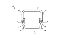
- FIG. 1 is a cross-sectional view of a bonded structure for press-formed parts according to the present invention.
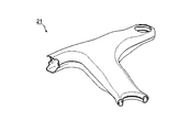
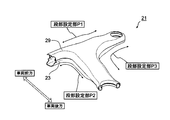
- FIG. 2 is a perspective view of an example of a suspension part for an automobile having a press-molded part joining structure according to the present invention.
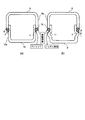
- FIG. 3 is a cross-sectional view illustrating the joining structure of the present invention and the conventional joining structure.
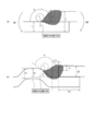
- Figure 4 is a diagram for explaining the meaning of calculation formula symbols stress concentration factor K t.
- FIG. 5 is a view for explaining a joint structure of press-formed parts according to the first embodiment.
- FIG. 6 is an explanatory diagram of a method for manufacturing a joined component according to Embodiment 2 (No. 1).
- FIG. 7 is an explanatory diagram of the method for manufacturing a joined component according to the second embodiment (part 2).
- FIG. 8 is an explanatory diagram of a method for producing a test piece in Example 1.
- FIG. 9 is an explanatory diagram of the shape of a plane bending fatigue test piece in Example 1.
- FIG. 10 is an explanatory diagram of a fatigue test method in Example 1.
- FIG. 11 is an explanatory diagram of the suspension arm according to the second embodiment.
- FIG. 12 is a cross-sectional view of the joined component according to the second embodiment.
- FIG. 13 is an explanatory diagram of a fatigue test method in Example 2.
- a press-molded part joining structure 1 according to Embodiment 1 of the present invention (hereinafter simply referred to as “joining structure 1”) has an opening on at least one side of a cross section produced by press molding as shown in FIG. The two parts having the above are joined together with the openings facing each other.
- the joint structure 1 is provided with a stepped portion 7 by forming a bent convex portion 5 protruding outward at the tip of the vertical wall portion 3 a in one component (lower component 3). It has been.
- the tip side of the step part 7 is fitted into the opening of the other part (upper part 9), the tip part of the vertical wall part 9 a of the upper part 9 and the step part 7 of the lower part 3. And are joined by arc welding.
- the suspension arm 21 extends from the vehicle body like an arm, and is a suspension part that controls the movement of the wheel. For example, when the vehicle is stopped by a brake, a load acting in the front-rear direction of the vehicle body is applied to the suspension arm 21. The maximum load that acts.
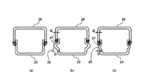
- the cross-sectional shape of the portion where the metal plates overlap is that of the metal plate of the lower part 10 as shown by the dotted line in FIG. 3 (a).
- the surface and the plate thickness edge of the metal plate of the upper part 9 have a right-angle shape.
- the part to be welded is the center (corner part) of the right-angled part, and the welding buildup is the intersection with the surface part of the metal plate of the lower part 3 and the surface part of the metal plate of the upper part 9 And the welding toe 11 and the welding toe 12 respectively.
- the distance between the weld toe 11 and the weld toe 12 is inevitably at least as long as the plate thickness of the upper part 9.
- Such a shape differs in thickness in the plate width direction and can be regarded as a member connected by a fillet, and it is necessary to consider a stress concentration factor when stress is concentrated on the fillet.
- the weld toe 11 on the lower part 3 side inevitably becomes a weld overlay for the inclined flat plate.
- Such a shape can be regarded as a member having a notch in the plate width direction, and it is necessary to consider a stress concentration factor when stress concentrates on the notch.
- Equation for calculating the stress concentration factor K t the case of welding to provide the following equation (1), and the stepped portion 7 in the case of conventional lap fillet welding the following equation (2).
- the meaning of the symbol of each formula is as the description after the formula and the description in FIG.
- ⁇ is an excess metal angle
- ⁇ is a radius of curvature
- T is the thickness of the overlapping portion
- t is the thickness of the lower plate
- h is the bead height.
- ⁇ is a surging angle
- ⁇ is a radius of curvature
- t 1 is a thickness of a plate provided with a step
- t 2 is a thickness of a flat plate
- h is a bead height.
- the shape of the weld overlay affects the shape of the weld metal after melting and solidifying. Therefore, compared with the conventional overlap fillet welding shown in FIG. 4A, the present invention in which the step 7 as shown in FIG. Therefore, in the present invention, the stress concentration factor K t is relaxed as compared with the conventional lap fillet welding. And compared with the joining structure welded by the conventional overlap fillet, the fatigue strength improves the direction of the joining structure 1 of this invention which provided the step part 7 and was welded.
- the site to be welded is the center of a right-angled portion where the end face of the upper part 9 and the surface of the vertical wall part 10a of the lower part 10 intersect ( Corner). Therefore, the weld toe 11 and the weld toe 12 are the intersection of the weld overlay and the metal plate surface of the lower part 10, and the intersection of the weld overlay and the metal plate surface of the upper part 9, respectively. Therefore, the molten steel of the metal tends to flow on the surface of the metal plate of the lower part 10 due to the action of gravity, and if there is a slight variation in the welding conditions or the surface state of the metal plate, the wettability of the molten metal of the weld metal is reduced. It changes and it becomes easy to generate
- the interfacial tension or gravity of the molten steel acts to act to equalize the unevenness in the molten steel itself. Therefore, in the present invention, welding unevenness hardly occurs and stable welding is possible, and as a result, the fatigue strength of the welded portion is improved.
- the propagation direction of the crack is substantially perpendicular to the surface of the lower part 3, and the propagation direction of the crack is parallel to the direction of repeated stress of fatigue (the surface of the lower part 3 is parallel).
- the propagation length of the crack is shortened.
- the surface of the lower part 3 is inclined (see FIG. 4B), and cracks are almost parallel to the plate thickness direction of the upper part 9. Propagate. For this reason, in the present invention, cracks propagate obliquely in the plate thickness direction in the stepped portion 7, and therefore the propagation length is longer than that of the conventional lap fillet welding. As a result, the joining structure 1 of the present invention has a fatigue life that is improved over conventional lap fillet welding.
- the joint structure 1 according to the present invention improves the rigidity of the parts as compared with the conventional lap fillet welding. That is, when the shape of the upper part 9 is the same as that of the conventional example and the step part 7 is provided in the lower part 3, the cross section of the lower part 3 is necessarily increased. When the same moment is applied, the maximum generated stress in the cross section at the same position becomes smaller as the section modulus (section modulus) becomes larger.
- the section modulus is a numerical value determined by the shape of the section. If the plate thickness is the same, the section having a larger section has a larger section coefficient. Therefore, the joint structure 1 according to the present invention has a larger section modulus and a smaller maximum generated stress, so that the rigidity is improved.
- FIG. 5 is an enlarged view of a portion where the upper part 9 and the lower part 3 are fitted in FIG.
- the thickness of the lower part 3 is t1
- the thickness of the upper part 9 is t2
- the height of the step 7 (the height of the bent convex part) is D
- the tip of the upper part 9 and the step 7 The distance from the lower end of the inclined surface is L1
- the fitting length of the lower part 3 to the upper part 9 is L2
- the inclination angle of the stepped part 7 is ⁇ .
- the relationship between the height D of the stepped portion 7 and the plate thickness t2 of the upper part 9 is preferably 0.5 * t2 ⁇ D ⁇ 2 * t2.
- the height of the stepped portion 7 exceeds 2 * t2, it is not preferable because molding of the upper part 9 and assembly of the upper part 9 and the lower part 3 become difficult.
- the distance L1 between the tip of the counterpart component (upper component 9) and the lower end of the inclined surface of the stepped portion 7 is preferably equal to or less than the plate thickness t2 of the counterpart component (upper component 9). This is because when the distance L1 is larger than the plate thickness t2, the weld toe 11 on the step portion 7 side is not on the inclined surface of the step portion 7, but on the surface of the lower part 3, so that FIG. This is because the effect due to the difference in shape compared in FIG. In this sense, the distance L1 is preferably shorter as long as the tip of the upper part 9 does not cover the inclined surface of the stepped portion 7.
- the inclination angle ⁇ formed by the inclined surface of the stepped portion 7 and the joint surface of the counterpart component (upper component 9) is preferably 90 ° ⁇ ⁇ ⁇ 150 °.
- the stepped portion 7 is provided by forming the bent convex portion 5 in the entire longitudinal direction (direction perpendicular to the paper surface) of the vertical wall portion 3a in the lower part 3 has been described. You may make it provide the level
- the joining structure 1 which concerns on this invention has provided the step part 7 by shape
- a vertical wall part is provided.
- a stepped portion 7 may be provided by molding the bent convex portion 5 on either the left side or the right side of 3a and joined to the vertical wall portion of the other component.
- the lower part 3 is provided with the stepped portion 7 and the tip of the lower part 3 is fitted and joined into the upper part 9.
- 9 may be provided with a stepped portion 7 so that the tip of the upper part 9 is fitted into the lower part 3 and joined.
- the method for manufacturing a joined part according to the second embodiment of the present invention mainly joins two parts having the joint structure 1 shown in FIG. 1 and having an opening on at least one side in combination with the openings facing each other.
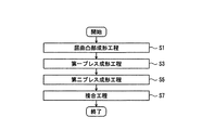
- the bending projection forming step (S 1), the first press forming step (S 3), the second press forming step (S 5), and the joining step (S 7) are intended for the joining component. I have.
- each process will be specifically described with reference to FIG.
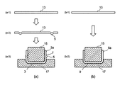
- the bent convex portion forming step S1 is a step of forming the bent convex portion 5 at a portion corresponding to the tip portion of the vertical wall portion 3a in the blank material 13 of one of the joined parts (FIG. 7 (a-)). 1), see FIG. 7 (a-2)).
- the height D of the bent convex portion 5 is preferably 0.5 * t2 ⁇ D ⁇ 2 * t2 in relation to the plate thickness t2 of the counterpart component (upper component 9).
- the inclination angle ⁇ formed by the inclined surface of the stepped portion 7 provided by the bent convex portion 5 and the joint surface of the counterpart component (upper component 9) is preferably 90 ° ⁇ ⁇ ⁇ 150 °.
- the front end portion of the vertical wall portion 3a formed in this step has a bent convex portion 5 protruding outwardly formed in the bent convex portion forming step S1.
- the lower part 3 manufactured in this process has a U-shaped cross section having an opening on at least one side of the cross section of the lower part 3. It becomes a shape.
- the second press molding step S5 is a step in which the blank 13 is press-molded with the punch 15 and the die 17 to obtain the upper part 9 having the vertical wall portion 9a (FIGS. 7B-1 and 7B-). 2)). Since the vertical wall portion 9a is formed, the upper part 9 produced in this step has a U-shaped cross-sectional shape having an opening on at least one side.
- the distance L1 between the front end of the plate of the upper part 9 and the lower end of the inclined surface of the step portion 7 may be set to be equal to or less than the plate thickness t2 of the upper part 9.
- the distance L1 is preferably shorter as long as the tip of the upper part 9 does not cover the inclined surface of the stepped portion 7.
- the second embodiment has the following effects.
- a suspension arm for an automobile is combined with two parts having an opening on at least one side of a cross section produced by press molding in the same manner as the joint part targeted in the second embodiment with the opening facing each other. It is joined.
- these two parts are not press-molded in a single process, and as a pre-process for press-molding the vertical wall of these two parts, the drawing process or blanking process of blank material used for press-molding is performed. Perform the process (without process).
- bent convex portion forming step By incorporating the bent convex portion forming step according to the present invention into these drawing step and punching step and forming the bent convex portion, without increasing the number of steps, and without requiring a special press molding device, It is possible to manufacture a bonded part that is economical and has high fatigue strength without impairing productivity.
- Example 1 An experiment was conducted to confirm the effects of the present invention. The details of this experiment will be described below.
- the durability performance of parts used in automotive vehicles is evaluated by incorporating the parts into an actual vehicle as a whole vehicle (full vehicle), evaluation in parts, and materials in smaller units ( There is an evaluation in the basic fatigue test of the test piece).
- Example 1 a basic fatigue test was performed using a test piece prepared by welding (see FIG. 8A) provided with a step portion according to the present invention and overlapped fillet welding of a conventional technique (see FIG. 8B). The performance of the joint structure was evaluated.
- test material was a 980 MPa class hot-rolled steel sheet having a plate thickness t2 of 2.3 mm.
- FIG. 8A shows a weld cross section of a test piece welded with a stepped portion 7 as an example of the present invention.
- the bent convex portion 5 was formed by bending and forming using a bender in the vicinity of the end portion on the length 250 mm side of one of the cut steel sheets.
- the height (depth) D of the step portion 7 provided by the formed bent convex portion 5 is 2.3 mm which is equal to the thickness t2 of the test material, and the step portion 7 formed by the bent convex portion 5 is used.
- the distance L1 between the tip of the upper part 9 and the lower end of the inclined surface of the stepped portion 7 was 2 mm.
- the end of the steel plate that has been cut out is superimposed on the end of the steel plate on which the bent convex portion 5 is formed, and the end surface on the side of the steel plate that has been cut out is MAG arc welded to have the joint structure of the present invention.
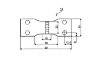
- a test piece was prepared. Then, a strip having a width of 30 mm was cut out from the test piece, and a plane bending fatigue test piece 19 was produced from the strip. As shown in FIG. 9, the plane bending fatigue test piece 19 had a length of 90 mm, a width of 30 mm, and a central portion having a width of 22 mm.
- FIG. 8 (b) shows a welded cross section of a test piece manufactured by conventional lap fillet welding as a comparative example.
- the steel plates as cut from the test material were overlapped and produced by MAG arc welding. Then, a strip having a width of 30 mm was cut out from the welded steel plate, and a plane bending fatigue test piece 19 having the shape shown in FIG. 9 was produced.
- the overlap margin (fitting length) L2 between the steel plates was 5 mm. Further, the weld bead width W was set to 5.5 mm or 7 mm so as to be the same in the inventive example and the comparative example.
- the arc welding conditions are set such that the welding current is 185 A or 205 A, the voltage is 19 V or 23 V, the welding speed is 85 cm / min, the shielding gas is Ar-20% CO 2 , the welding wire For 780 MPa class high strength steel with a diameter of 1.2 mm was used. Table 1 shows the arc welding conditions.
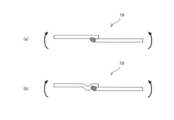
- the fatigue test was performed by pulsating plane bending (see FIG. 10).
- a PBF-30 manufactured by Tokyo Henki was used as a testing machine, and was set in the testing machine so that the weld bead of the plane bending fatigue test piece 19 faced downward.
- the upper plate is fixed to the driving arm side of the testing machine
- the lower plate is fixed to the measurement swing arm side of the testing machine
- the plane bending fatigue test piece 19 is placed so that the center of the thickness of the lower plate becomes a bending neutral surface. installed.
- a load was repeatedly applied so that the target stress was applied to the plane bending fatigue test piece 19 through the drive arm, and the test was performed until the plane bending fatigue test piece 19 cracked.
- the stress applied to the plane bending fatigue test piece 19 was obtained from the moment measured through the measuring arm, and the plate thickness and plate width (average value of the upper plate and the lower plate) of the plane bending fatigue test piece 19.
- the fatigue test conditions were a stress ratio of 0 (one swing), a test frequency of 20 Hz, and the fatigue test was terminated at a maximum of 10 million times.
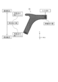
- the suspension arm 21 shown in FIG. 11 is the target, and welding of providing a conventional fillet fillet welding or a stepped portion of the present invention at a joint between two parts (stepped portion setting portions P1, P2, P3).
- a fatigue test was performed on the suspension arm 21 manufactured in the above, and the present invention was compared with the prior art.
- the two parts constituting the suspension arm 21 are formed by press-forming a 980 MPa class hot-rolled steel sheet having a plate thickness t2 of 2.3 mm in a U-shaped cross section, and one part 29 is identical between the invention example and the conventional example.
- the arc welding conditions were a welding current of 185 A, a voltage of 23 V, a welding speed of 85 cm / min, a shielding gas of Ar-20% CO 2 , and a welding wire used for 780 MPa class high strength steel with a diameter of 1.2 mm. .
- the stepped portion 27 was not provided on the other component 23, and overlapped fillet welding was performed at all the joint portions (P1 to P3 in FIG. 11).
- the step part 27 was provided by shape
- the parts where the bent convex portion 25 is formed and the stepped portion 27 is set include two conditions when the stepped portion setting portions P1, P2 and P3 shown in FIG. 11 are all and only the stepped portion setting portion P3. did.
- Table 2 shows the step height and the condition of the step setting portion in this example.
- Table 3 shows the results of the fatigue test.
- the example of the present invention welded with the stepped portion 27 increases the number of repetitions until a crack occurs compared to the conventional example, and the stepped portion 27 is provided to join the two parts. As a result, the fatigue life was increased.
- the effect of increasing the fatigue strength of the welded part and increasing the fatigue life of the joined part is demonstrated by providing a step at the site where the two parts are joined, compared to conventional lap fillet welding. It was.
- the section modulus (section modulus) of the joined part increases, which contributes to the increase in rigidity and is expected to reduce weight (weight reduction of automotive body) it can.
- the present invention is a suspension frame or chassis that requires high strength in a joined part having a closed cross-sectional shape by joining two parts. It can be easily applied to the manufacture of a frame, and an improvement in fatigue strength and rigidity can be obtained.
- the present invention can be applied to a joined structure of a press-formed part, an automotive structural part having the joined structure, and a method of manufacturing the joined part.
Landscapes
- Engineering & Computer Science (AREA)
- Mechanical Engineering (AREA)
- Physics & Mathematics (AREA)
- Plasma & Fusion (AREA)
- Transportation (AREA)
- Combustion & Propulsion (AREA)
- Chemical & Material Sciences (AREA)
- Butt Welding And Welding Of Specific Article (AREA)
- Body Structure For Vehicles (AREA)
- Shaping Metal By Deep-Drawing, Or The Like (AREA)
- Vehicle Body Suspensions (AREA)
- Arc Welding In General (AREA)
- Lining Or Joining Of Plastics Or The Like (AREA)
Priority Applications (5)
| Application Number | Priority Date | Filing Date | Title |
|---|---|---|---|
| MX2017010266A MX2017010266A (es) | 2015-02-12 | 2016-01-27 | Estructura de soldadura de la parte moldeada por presion, parte estructural para carroceria automotriz que incluye la estructura de soldadura, y metodo para la fabricacion de parte de soldadura. |
| CN201680009443.4A CN107206858B (zh) | 2015-02-12 | 2016-01-27 | 冲压成形部件的接合构造、具有该接合构造的汽车用构造部件以及接合部件的制造方法 |
| EP16749034.1A EP3257690B1 (en) | 2015-02-12 | 2016-01-27 | Structure for bonding press-molded article, structural article for automobile having said bonding structure, and method for manufacturing bonded article |
| US15/546,554 US20180009050A1 (en) | 2015-02-12 | 2016-01-27 | Welding structure of press formed part, structural part for automotive body including the welding structure, and method for manufacturing welding part (as amended) |
| KR1020177022523A KR101967571B1 (ko) | 2015-02-12 | 2016-01-27 | 프레스 성형 부품의 접합 구조, 그 접합 구조를 갖는 자동차용 구조 부품 및 접합 부품의 제조 방법 |
Applications Claiming Priority (2)
| Application Number | Priority Date | Filing Date | Title |
|---|---|---|---|
| JP2015-025531 | 2015-02-12 | ||
| JP2015025531A JP6168077B2 (ja) | 2015-02-12 | 2015-02-12 | プレス成形部品の接合構造、該接合構造を有する自動車用構造部品及び接合部品の製造方法 |
Publications (1)
| Publication Number | Publication Date |
|---|---|
| WO2016129389A1 true WO2016129389A1 (ja) | 2016-08-18 |
Family
ID=56615367
Family Applications (1)
| Application Number | Title | Priority Date | Filing Date |
|---|---|---|---|
| PCT/JP2016/052321 Ceased WO2016129389A1 (ja) | 2015-02-12 | 2016-01-27 | プレス成形部品の接合構造、該接合構造を有する自動車用構造部品及び接合部品の製造方法 |
Country Status (7)
| Country | Link |
|---|---|
| US (1) | US20180009050A1 (enExample) |
| EP (1) | EP3257690B1 (enExample) |
| JP (1) | JP6168077B2 (enExample) |
| KR (1) | KR101967571B1 (enExample) |
| CN (1) | CN107206858B (enExample) |
| MX (1) | MX2017010266A (enExample) |
| WO (1) | WO2016129389A1 (enExample) |
Cited By (1)
| Publication number | Priority date | Publication date | Assignee | Title |
|---|---|---|---|---|
| WO2022190687A1 (ja) * | 2021-03-09 | 2022-09-15 | 株式会社ワイテック | アーク溶接方法 |
Families Citing this family (19)
| Publication number | Priority date | Publication date | Assignee | Title |
|---|---|---|---|---|
| WO2018129256A1 (en) * | 2017-01-06 | 2018-07-12 | Keystone Tower Systems, Inc. | Tube stiffening |
| CN110337344B (zh) * | 2017-02-28 | 2022-05-13 | 杰富意钢铁株式会社 | 搭接角焊缝电弧焊接头及其制造方法 |
| JP6913174B2 (ja) * | 2017-10-05 | 2021-08-04 | 株式会社ノザワ | 建築用パネルの取付金具及びそれを用いた建築用パネルの取付構造 |
| JP6863218B2 (ja) * | 2017-10-12 | 2021-04-21 | トヨタ自動車株式会社 | サスペンションアームの溶接方法 |
| US11413919B2 (en) * | 2017-11-27 | 2022-08-16 | Nippon Steel Corporation | Structural member |
| JP6922753B2 (ja) * | 2018-01-16 | 2021-08-18 | Jfeスチール株式会社 | 溶接接合構造体および溶接接合方法 |
| JP7073732B2 (ja) * | 2018-01-16 | 2022-05-24 | 大同特殊鋼株式会社 | 溶接ビードの外観評価方法および外観評価装置 |
| DE102018210174A1 (de) * | 2018-06-22 | 2019-12-24 | Thyssenkrupp Ag | Verfahren zur Herstellung eines Trägers und eines Leiter- oder Kastenrahmens |
| JP7181016B2 (ja) * | 2018-06-29 | 2022-11-30 | 株式会社神戸製鋼所 | 接合構造体及びその製造方法 |
| JP7143186B2 (ja) | 2018-11-12 | 2022-09-28 | 三菱重工業株式会社 | 部品製造方法、加工装置及び部品 |
| DE102018131754A1 (de) * | 2018-12-11 | 2020-06-18 | Bayerische Motoren Werke Aktiengesellschaft | Verfahren zur Herstellung von Fahrzeugersatzteilen |
| CN109500486B (zh) * | 2018-12-22 | 2023-01-03 | 山西汾西重工有限责任公司 | 铝合金厚板卷圆壳体的纵向对接缝的定位及焊接方法 |
| JP7269469B2 (ja) * | 2019-03-13 | 2023-05-09 | 日本製鉄株式会社 | サスペンションアーム、および、自動車サスペンション構造 |
| US11724746B2 (en) * | 2021-10-13 | 2023-08-15 | GM Global Technology Operations LLC | Chassis assembly having mixed materials |
| US12157277B2 (en) | 2021-12-30 | 2024-12-03 | Rohr, Inc. | Vibration welding fiber-reinforced composite aircraft structures |
| JP2023151981A (ja) * | 2022-04-01 | 2023-10-16 | 日本製鉄株式会社 | 金属部材の製造方法及び金属部材 |
| KR102504571B1 (ko) * | 2022-04-22 | 2023-03-02 | 기승공업(주) | 자동차 현가장치의 리어 트레일링 암 가공방법 및 금형 |
| JP7538462B1 (ja) * | 2023-04-03 | 2024-08-22 | 日本製鉄株式会社 | 構造部材 |
| WO2024210057A1 (ja) * | 2023-04-03 | 2024-10-10 | 日本製鉄株式会社 | 構造部材 |
Citations (6)
| Publication number | Priority date | Publication date | Assignee | Title |
|---|---|---|---|---|
| JPS57139475U (enExample) * | 1981-02-26 | 1982-08-31 | ||
| JPS5896869U (ja) * | 1981-12-25 | 1983-07-01 | トヨタ自動車株式会社 | 薄鋼板のア−ク溶接継手構造 |
| JPS62296969A (ja) * | 1986-06-16 | 1987-12-24 | Seiwa Kogyosho:Kk | 電気温水器等の缶体の製造方法 |
| JPH079135A (ja) * | 1993-06-25 | 1995-01-13 | Fuji Heavy Ind Ltd | 板部材の結合方法 |
| JPH10113717A (ja) * | 1996-10-11 | 1998-05-06 | Nakajima Kokan Kk | 四角形鋼管の製造方法 |
| JP2001047231A (ja) * | 1999-08-04 | 2001-02-20 | Topre Corp | 重ね合わせ溶接法 |
Family Cites Families (10)
| Publication number | Priority date | Publication date | Assignee | Title |
|---|---|---|---|---|
| DE417167C (de) * | 1922-02-16 | 1925-08-06 | Eugen Wolf Dr | Durch autogenes Schweissen hergestellte Verbindung von Metallteilen |
| FR2520648B1 (fr) * | 1982-01-29 | 1986-06-13 | Cimt Lorraine | Procede d'assemblage par soudage bord a bord de profiles et paroi obtenue par ce procede |
| JPS635873A (ja) * | 1986-06-25 | 1988-01-11 | Diesel Kiki Co Ltd | パイプとパイプの溶接方法 |
| US5476210A (en) * | 1993-06-25 | 1995-12-19 | Fuji Jukogyo Kabushiki Kaisha | Structure for joining plate elements and method for joining the same |
| JP3362624B2 (ja) | 1997-01-10 | 2003-01-07 | 日本鋼管株式会社 | 重ね溶接継手の疲労特性向上方法 |
| FI110238B (fi) * | 2001-01-31 | 2002-12-31 | Innowork Oy | Menetelmä kotelopalkin valmistamiseksi sekä menetelmän mukaan valmistettu kotelopalkki ja kotelopalkin rakenneosa |
| GB2403172A (en) * | 2003-06-17 | 2004-12-29 | Bamford Excavators Ltd | Method of forming a metal box section |
| JP6373550B2 (ja) | 2011-03-31 | 2018-08-15 | Jfeスチール株式会社 | ガスシールドアーク溶接方法 |
| JP5617813B2 (ja) | 2011-10-11 | 2014-11-05 | トヨタ自動車株式会社 | サスペンションアーム |
| JP5898576B2 (ja) | 2012-06-25 | 2016-04-06 | 株式会社神戸製鋼所 | 多層アーク溶接継手の製造方法 |
-
2015
- 2015-02-12 JP JP2015025531A patent/JP6168077B2/ja active Active
-
2016
- 2016-01-27 MX MX2017010266A patent/MX2017010266A/es unknown
- 2016-01-27 WO PCT/JP2016/052321 patent/WO2016129389A1/ja not_active Ceased
- 2016-01-27 CN CN201680009443.4A patent/CN107206858B/zh active Active
- 2016-01-27 US US15/546,554 patent/US20180009050A1/en not_active Abandoned
- 2016-01-27 KR KR1020177022523A patent/KR101967571B1/ko active Active
- 2016-01-27 EP EP16749034.1A patent/EP3257690B1/en active Active
Patent Citations (6)
| Publication number | Priority date | Publication date | Assignee | Title |
|---|---|---|---|---|
| JPS57139475U (enExample) * | 1981-02-26 | 1982-08-31 | ||
| JPS5896869U (ja) * | 1981-12-25 | 1983-07-01 | トヨタ自動車株式会社 | 薄鋼板のア−ク溶接継手構造 |
| JPS62296969A (ja) * | 1986-06-16 | 1987-12-24 | Seiwa Kogyosho:Kk | 電気温水器等の缶体の製造方法 |
| JPH079135A (ja) * | 1993-06-25 | 1995-01-13 | Fuji Heavy Ind Ltd | 板部材の結合方法 |
| JPH10113717A (ja) * | 1996-10-11 | 1998-05-06 | Nakajima Kokan Kk | 四角形鋼管の製造方法 |
| JP2001047231A (ja) * | 1999-08-04 | 2001-02-20 | Topre Corp | 重ね合わせ溶接法 |
Non-Patent Citations (1)
| Title |
|---|
| See also references of EP3257690A4 * |
Cited By (1)
| Publication number | Priority date | Publication date | Assignee | Title |
|---|---|---|---|---|
| WO2022190687A1 (ja) * | 2021-03-09 | 2022-09-15 | 株式会社ワイテック | アーク溶接方法 |
Also Published As
| Publication number | Publication date |
|---|---|
| MX2017010266A (es) | 2018-02-13 |
| CN107206858B (zh) | 2020-05-19 |
| CN107206858A (zh) | 2017-09-26 |
| KR20170105062A (ko) | 2017-09-18 |
| KR101967571B1 (ko) | 2019-04-09 |
| US20180009050A1 (en) | 2018-01-11 |
| EP3257690B1 (en) | 2025-01-15 |
| EP3257690A1 (en) | 2017-12-20 |
| JP6168077B2 (ja) | 2017-07-26 |
| EP3257690A4 (en) | 2018-03-14 |
| JP2016147593A (ja) | 2016-08-18 |
Similar Documents
| Publication | Publication Date | Title |
|---|---|---|
| WO2016129389A1 (ja) | プレス成形部品の接合構造、該接合構造を有する自動車用構造部品及び接合部品の製造方法 | |
| JP6265089B2 (ja) | 自動車用足廻り部品の疲労強度向上方法 | |
| JP6119844B2 (ja) | 自動車用構造部材、及びその製造方法 | |
| US11420472B2 (en) | Front axle beam and production method thereof | |
| JP5994879B2 (ja) | 重ね隅肉アーク溶接継手 | |
| JP5154672B2 (ja) | 自動車用骨格部品 | |
| JPWO2010128540A1 (ja) | テーラードブランク材およびそれを用いた構造部材の製造方法 | |
| WO2020209357A1 (ja) | ブランクおよび構造部材 | |
| JP2019073152A (ja) | サイドレールおよびサイドレールの製造方法 | |
| WO2017073129A1 (ja) | 重ね隅肉アーク溶接継手及びプレス成形部品の接合構造 | |
| JP6299702B2 (ja) | 自動車用骨格部品および自動車用骨格部品の製造方法 | |
| JP6614183B2 (ja) | 自動車用パネル部材 | |
| JP5320952B2 (ja) | 突合せ溶接ワークの強化方法及び突合せ溶接ワーク | |
| JP6984495B2 (ja) | 隅肉溶接継手及びその製造方法 | |
| JP2017196950A (ja) | 接合構造体、該接合構造体の製造方法 | |
| JP2716956B2 (ja) | 自動車アウターパネルの製造方法 | |
| JP4764015B2 (ja) | 接合金属板の製造方法 | |
| JP2001122154A (ja) | 差厚ブランク材 | |
| JP2024042975A (ja) | 溶接継手の応力拡大係数推定方法 | |
| JP2025064091A (ja) | 溶接継手の応力拡大係数推定方法 | |
| JP2023122747A (ja) | 構造部材 | |
| JP2001239802A (ja) | アクスルハウジング及びその製造方法 |
Legal Events
| Date | Code | Title | Description |
|---|---|---|---|
| 121 | Ep: the epo has been informed by wipo that ep was designated in this application |
Ref document number: 16749034 Country of ref document: EP Kind code of ref document: A1 |
|
| REEP | Request for entry into the european phase |
Ref document number: 2016749034 Country of ref document: EP |
|
| WWE | Wipo information: entry into national phase |
Ref document number: 15546554 Country of ref document: US |
|
| WWE | Wipo information: entry into national phase |
Ref document number: MX/A/2017/010266 Country of ref document: MX |
|
| ENP | Entry into the national phase |
Ref document number: 20177022523 Country of ref document: KR Kind code of ref document: A |
|
| NENP | Non-entry into the national phase |
Ref country code: DE |