WO2016121651A1 - 光感応性複合材料とその製造方法、および光感応性複合材料フィルムの使用方法 - Google Patents
光感応性複合材料とその製造方法、および光感応性複合材料フィルムの使用方法 Download PDFInfo
- Publication number
- WO2016121651A1 WO2016121651A1 PCT/JP2016/051877 JP2016051877W WO2016121651A1 WO 2016121651 A1 WO2016121651 A1 WO 2016121651A1 JP 2016051877 W JP2016051877 W JP 2016051877W WO 2016121651 A1 WO2016121651 A1 WO 2016121651A1
- Authority
- WO
- WIPO (PCT)
- Prior art keywords
- composite material
- light
- compound
- photosensitive composite
- film
- Prior art date
- Legal status (The legal status is an assumption and is not a legal conclusion. Google has not performed a legal analysis and makes no representation as to the accuracy of the status listed.)
- Ceased
Links
Images







Classifications
-
- C—CHEMISTRY; METALLURGY
- C09—DYES; PAINTS; POLISHES; NATURAL RESINS; ADHESIVES; COMPOSITIONS NOT OTHERWISE PROVIDED FOR; APPLICATIONS OF MATERIALS NOT OTHERWISE PROVIDED FOR
- C09J—ADHESIVES; NON-MECHANICAL ASPECTS OF ADHESIVE PROCESSES IN GENERAL; ADHESIVE PROCESSES NOT PROVIDED FOR ELSEWHERE; USE OF MATERIALS AS ADHESIVES
- C09J5/00—Adhesive processes in general; Adhesive processes not provided for elsewhere, e.g. relating to primers
-
- C—CHEMISTRY; METALLURGY
- C09—DYES; PAINTS; POLISHES; NATURAL RESINS; ADHESIVES; COMPOSITIONS NOT OTHERWISE PROVIDED FOR; APPLICATIONS OF MATERIALS NOT OTHERWISE PROVIDED FOR
- C09J—ADHESIVES; NON-MECHANICAL ASPECTS OF ADHESIVE PROCESSES IN GENERAL; ADHESIVE PROCESSES NOT PROVIDED FOR ELSEWHERE; USE OF MATERIALS AS ADHESIVES
- C09J7/00—Adhesives in the form of films or foils
- C09J7/10—Adhesives in the form of films or foils without carriers
-
- C—CHEMISTRY; METALLURGY
- C08—ORGANIC MACROMOLECULAR COMPOUNDS; THEIR PREPARATION OR CHEMICAL WORKING-UP; COMPOSITIONS BASED THEREON
- C08J—WORKING-UP; GENERAL PROCESSES OF COMPOUNDING; AFTER-TREATMENT NOT COVERED BY SUBCLASSES C08B, C08C, C08F, C08G or C08H
- C08J5/00—Manufacture of articles or shaped materials containing macromolecular substances
- C08J5/18—Manufacture of films or sheets
-
- C—CHEMISTRY; METALLURGY
- C08—ORGANIC MACROMOLECULAR COMPOUNDS; THEIR PREPARATION OR CHEMICAL WORKING-UP; COMPOSITIONS BASED THEREON
- C08K—Use of inorganic or non-macromolecular organic substances as compounding ingredients
- C08K5/00—Use of organic ingredients
- C08K5/16—Nitrogen-containing compounds
- C08K5/22—Compounds containing nitrogen bound to another nitrogen atom
- C08K5/23—Azo-compounds
-
- C—CHEMISTRY; METALLURGY
- C08—ORGANIC MACROMOLECULAR COMPOUNDS; THEIR PREPARATION OR CHEMICAL WORKING-UP; COMPOSITIONS BASED THEREON
- C08L—COMPOSITIONS OF MACROMOLECULAR COMPOUNDS
- C08L101/00—Compositions of unspecified macromolecular compounds
-
- C—CHEMISTRY; METALLURGY
- C09—DYES; PAINTS; POLISHES; NATURAL RESINS; ADHESIVES; COMPOSITIONS NOT OTHERWISE PROVIDED FOR; APPLICATIONS OF MATERIALS NOT OTHERWISE PROVIDED FOR
- C09J—ADHESIVES; NON-MECHANICAL ASPECTS OF ADHESIVE PROCESSES IN GENERAL; ADHESIVE PROCESSES NOT PROVIDED FOR ELSEWHERE; USE OF MATERIALS AS ADHESIVES
- C09J11/00—Features of adhesives not provided for in group C09J9/00, e.g. additives
- C09J11/02—Non-macromolecular additives
- C09J11/06—Non-macromolecular additives organic
-
- C—CHEMISTRY; METALLURGY
- C09—DYES; PAINTS; POLISHES; NATURAL RESINS; ADHESIVES; COMPOSITIONS NOT OTHERWISE PROVIDED FOR; APPLICATIONS OF MATERIALS NOT OTHERWISE PROVIDED FOR
- C09J—ADHESIVES; NON-MECHANICAL ASPECTS OF ADHESIVE PROCESSES IN GENERAL; ADHESIVE PROCESSES NOT PROVIDED FOR ELSEWHERE; USE OF MATERIALS AS ADHESIVES
- C09J11/00—Features of adhesives not provided for in group C09J9/00, e.g. additives
- C09J11/08—Macromolecular additives
-
- C—CHEMISTRY; METALLURGY
- C09—DYES; PAINTS; POLISHES; NATURAL RESINS; ADHESIVES; COMPOSITIONS NOT OTHERWISE PROVIDED FOR; APPLICATIONS OF MATERIALS NOT OTHERWISE PROVIDED FOR
- C09J—ADHESIVES; NON-MECHANICAL ASPECTS OF ADHESIVE PROCESSES IN GENERAL; ADHESIVE PROCESSES NOT PROVIDED FOR ELSEWHERE; USE OF MATERIALS AS ADHESIVES
- C09J201/00—Adhesives based on unspecified macromolecular compounds
-
- C—CHEMISTRY; METALLURGY
- C09—DYES; PAINTS; POLISHES; NATURAL RESINS; ADHESIVES; COMPOSITIONS NOT OTHERWISE PROVIDED FOR; APPLICATIONS OF MATERIALS NOT OTHERWISE PROVIDED FOR
- C09J—ADHESIVES; NON-MECHANICAL ASPECTS OF ADHESIVE PROCESSES IN GENERAL; ADHESIVE PROCESSES NOT PROVIDED FOR ELSEWHERE; USE OF MATERIALS AS ADHESIVES
- C09J7/00—Adhesives in the form of films or foils
Definitions
- the present invention relates to a light-sensitive composite material suitable for uses such as an adhesive film, a self-healing paint, and a self-healing film.
- thermosetting composition for an adhesive a composition containing an epoxy resin having two or more epoxy groups in one molecule, a specific solid triazine derivative as a curing agent, and an ionic liquid is known.
- Patent Document 1 a composition containing an epoxy resin having two or more epoxy groups in one molecule, a specific solid triazine derivative as a curing agent, and an ionic liquid is known.
- Patent Document 2 a composition containing a compound containing a maleimide group and an ethylenically unsaturated group, a compound containing an ethylenically unsaturated group, and a photopolymerization initiator.
- These materials all exhibit good properties as an adhesive, but once the adhesive is cured by the action of heat or light, the adherends are peeled off and then reused as an adhesive. There was a problem that it could not be used.
- An object of the present invention is to provide a photosensitive composite material that can be repeatedly used as an adhesive by reversibly changing the hardness of the material.
- the present inventor changed the glass transition temperature by irradiating light-sensitive composite materials containing a polymer compound, a liquid crystal compound, and a photo-responsive compound with light of different wavelengths, and this photo-sensitive composite material. It was found that the hardness of can be reversibly changed.
- the change in the glass transition temperature of the photosensitive composite material is accompanied by the change in the molecular shape of the photoresponsive material due to light irradiation. Since the hardness of the light-sensitive composite material reversibly changes, the light-sensitive composite material has a function of adhesion and adhesion and can be used repeatedly.
- the photosensitive composite material of the present invention includes a polymer compound, a liquid crystal compound dispersed in a granular form in the polymer compound, a photoresponsive compound whose molecular shape is reversibly changed by irradiation with light of different wavelengths, and Containing.
- the difference between the solubility parameter of the polymer compound and the solubility parameter of the liquid crystal compound is preferably 10 or less.
- the photoresponsive compound may be an azobenzene derivative.
- the mass of the polymer compound is preferably 40% to 60% of the total mass.
- the mass of the photoresponsive compound relative to the sum of the mass of the liquid crystal compound and the mass of the photoresponsive compound is preferably 2% to 100%.
- light of different wavelengths is ultraviolet light and visible light
- the glass transition temperature is lowered by ultraviolet light irradiation
- the glass transition temperature lowered by ultraviolet light irradiation is reduced by visible light irradiation. It is preferable to rise.
- the light-sensitive composite material film of the present invention is obtained by molding the light-sensitive composite material of the present invention into a film.
- the photosensitive composite material film of the present invention can be used as an adhesive film for attaching a decorative article to a nail.
- the method for producing a photosensitive composite material of the present invention includes a polymer compound, a liquid crystal compound dispersed in a granular form in the polymer compound, and an optical response in which the molecular shape reversibly changes by irradiation with light of different wavelengths.
- the method for repairing damaged or cut sites of the photosensitive composite material according to the present invention comprises a polymer compound, a liquid crystal compound dispersed in a granular form in the polymer compound, and a molecular shape by irradiation with ultraviolet light and visible light.
- a method for repairing a damaged or cut site of a photosensitive composite material comprising a photoreactive compound that reversibly changes, wherein the damaged or cut site of the photosensitive composite material is irradiated with ultraviolet light, It has a restoration process for softening the damaged site or sticking the cut site, and a curing step for irradiating the damaged site or the cut site with visible light and curing the damaged site or the cut site after the restoration step.
- the method of using the light-sensitive composite film of the present invention is such that the molecular shape is reversibly changed by irradiation with ultraviolet light and visible light, a polymer compound, a liquid crystal compound dispersed in a granular form in the polymer compound, and ultraviolet light and visible light.
- Pressing process for pressing the photosensitive composite material film against the object to be adhered, a pasting process for pasting the adhesive onto the light sensitive composite film pressed against the object to be adhered, and a photosensitive composite material after the pasting process A curing step of irradiating the film with visible light to cure the photosensitive composite material film.
- a photosensitive composite material that can be repeatedly used as an adhesive is obtained.
- FIG. The graph which shows the tensile shear test result of the photosensitive composite material 3.
- FIG. An image when a film of the photosensitive composite material 3 is provided on the surface of the artificial nail.
- the photosensitive composite material of the present invention contains a polymer compound, a liquid crystal compound, and a photoresponsive compound.
- the liquid crystal compound is dispersed in a granular form in the polymer compound. That is, the polymer compound forms a sponge-like structure in the photosensitive composite material, and the liquid crystal compound is present in the pores of this structure.
- the photoresponsive compound reversibly changes its molecular shape when irradiated with light of different wavelengths. When the light-sensitive composite material of the present invention is irradiated with light, the molecular shape of the photoresponsive compound changes, and the glass transition temperature of the light-sensitive composite material changes accordingly.
- the glass transition temperature of the light-sensitive composite material decreases and becomes soft at room temperature. And after adhering adherends through this soft photosensitive composite material, the glass transition temperature of the photosensitive composite material rises by irradiating light of a wavelength B different from the wavelength A, and at room temperature. If it becomes hard, it will be in the state which adherends adhered.
- the light-sensitive composite material is softened by irradiating the light-sensitive composite material with light of wavelength A again, and the adherends can be peeled off.
- the soft state and the hard state can be reversibly changed at room temperature by irradiation with light of wavelength A and wavelength B. Therefore, the photosensitive composite material of the present invention can be repeatedly used as an adhesive.
- the photosensitive composite material of this invention contains a high molecular compound, it can be shape
- a general polymer compound can be used as the polymer compound.
- Specific examples include acrylic polymers, methacrylic polymers, styrene polymers, olefin polymers, vinyl polymers, and the like. These polymer compounds may be used alone or in combination of two or more.
- a crosslinked polymer compound obtained by chemically crosslinking the polymer compound can also be used.
- the polymer compound preferably has a weight average molecular weight of 20000 or more. This is because when the weight average molecular weight of the polymer compound is too low, good entanglement between the polymer compounds does not occur and the tackiness and adhesiveness are lowered.
- the mass of the polymer compound is preferably 40% to 90%, more preferably 40% to 60% of the total mass of the photosensitive composite material.
- “ ⁇ ” is described between two numerical values to express a numerical range, these two numerical values are also included in the numerical range.
- the mass of the polymer compound in the photosensitive composite material is too small, the polymer compound and the liquid crystal compound are easily separated in the photosensitive composite material, and the adhesive force is reduced.
- the mass of the polymer compound in the light-sensitive composite material is too large, the glass transition temperature does not change much even when the light-sensitive composite material is irradiated with light, so that it is difficult to obtain a good adhesive state.
- one or more common liquid crystal compounds can be used as the liquid crystal compound.
- the liquid crystal compound functions as a plasticizer for the polymer compound, and an optimal liquid crystal compound is selected depending on the combination with the polymer compound.
- the storage elastic modulus G ′ which is an index of the hardness of the photosensitive composite material, is on the order of 10 5 Pa or more, and this photosensitive composite material is excellent in adhesiveness.
- the photosensitive composite material in which the polymer compound is contained in a granular form in the liquid crystal compound has poor adhesion.
- the liquid crystal compound preferably exhibits a liquid crystal phase at room temperature.
- the mass of the liquid crystal compound is preferably 10% to 60%, more preferably 40% to 60% of the entire photosensitive composite material. Examples of the liquid crystal compound that can be used in the present invention include 4-cyano-4′-pentylbiphenyl.
- the mass of the liquid crystal compound in the light sensitive composite material is too large, the polymer compound and the liquid crystal compound are easily separated in the light sensitive composite material, and the adhesive force is reduced.
- the mass in the light-sensitive composite material is too small, the glass transition temperature does not drop much even when the light-sensitive composite material is irradiated with light, and the hardness of the light-sensitive composite material does not change much. For this reason, it is difficult to obtain a good adhesion state.
- a suitable combination of the polymer compound and the liquid crystal compound can be determined using the solubility parameter used for the compatibility evaluation between the polymer compound and the plasticizer.
- the solubility parameter used for the compatibility evaluation between the polymer compound and the plasticizer In general, it is known that the closer the solubility parameter values of the polymer compound and the plasticizer are, the easier they are to mix, and the farther the solubility parameter value is, the harder they are to mix.
- the difference in solubility parameter between the two is preferably 10 or less, more preferably 5 or less, and 2 or less. More preferably.
- the solubility parameter of polymethyl methacrylate which is a polymer compound
- the solubility parameter of 4-cyano-4′-pentylbiphenyl, which is a liquid crystal compound is 10.95. 1.45 to 1.85.
- a photosensitive composite material using polymethyl methacrylate as the polymer compound and 4-cyano-4'-pentylbiphenyl as the liquid crystal compound, respectively, is easy to mix with the polymer compound and the liquid crystal compound. Is excellent.
- the photoresponsive compound changes its molecular shape due to light absorption, that is, the photoisomerization reaction significantly changes the polarity and molecular size, or changes the phase structure of the liquid crystal compound from the liquid crystal phase to the isotropic phase. It is a compound that can be. Specifically, an azobenzene derivative is mentioned as a photoresponsive compound.
- an azobenzene derivative is mentioned as a photoresponsive compound.
- the photoresponsive compound is preferably dissolved in the liquid crystal compound. By uniformly mixing the light-responsive compound and the liquid crystal compound, the phase structure of the liquid crystal compound is likely to change when the light-sensitive composite material is irradiated with light, and the glass transition temperature of the light-sensitive composite material changes. Because it grows.
- the wavelength of the irradiation light is appropriately selected from ultraviolet light, visible light, near infrared light, and the like according to the photoresponsive compound. Among these, light with a wavelength of 254 nm to 1064 nm is preferable, and light with a wavelength of 365 nm to 632 nm is more preferable.
- Light with a wavelength of 254 nm to 1064 nm can be emitted from a general light source that is commercially available, and light with a wavelength of 365 nm to 632 nm is a more versatile light source such as a mercury lamp light source, an argon ion laser light source, or helium-neon It is because it can irradiate from a laser light source.
- the molecular shape of the photoresponsive compound is reversibly changed by irradiation with ultraviolet light and visible light. That is, for example, it is preferable that the glass transition temperature is lowered by ultraviolet light irradiation, and the glass transition temperature lowered by ultraviolet light irradiation is increased by visible light irradiation.
- the intensity of the irradiation light is appropriately selected according to the content of the photoresponsive compound in the photosensitive composite material, but is preferably 0.2 mW / cm 2 or more. This is because if the intensity of the irradiation light is too small, the photoisomerization reaction of the photoresponsive compound cannot be sufficiently induced.
- the upper limit of the intensity of irradiation light is not particularly limited. However, from a practical viewpoint, 0.2 mW / cm 2 to 200 mW / cm 2 is preferable, and 1 mW / cm 2 to 200 mW / cm 2 is more preferable.
- the mass of the photoresponsive compound relative to the sum of the mass of the liquid crystal compound and the photoresponsive compound is preferably 2% to 100%. If the mass of the photoresponsive compound relative to the sum of the mass of the liquid crystal compound and the photoresponsive compound is too small, the glass transition point due to the photoisomerization reaction of the photosensitive composite material does not sufficiently change, and the photosensitivity The hardness of the composite material does not change much. For this reason, it is difficult to obtain a good adhesion state.
- a photoresponsive compound shows liquid crystallinity at room temperature
- a photoresponsive compound can also be used as a liquid crystal compound. That is, only the photoresponsive compound may be used in place of the mixture of the liquid crystal compound and the photoresponsive compound.
- the mass of the photoresponsive compound with respect to the sum of the mass of the liquid crystal compound and the photoresponsive compound is 100% when the photoresponsive compound exhibits liquid crystallinity at room temperature and only the photoresponsive compound is used. is there.
- the method for producing a photosensitive composite material according to the present invention includes a dissolution step of dissolving a polymer compound, a liquid crystal compound, and a photoresponsive compound in a volatile organic solvent, and then a solvent removal step of removing the organic solvent. And.
- a dissolution step of dissolving a polymer compound, a liquid crystal compound, and a photoresponsive compound in a volatile organic solvent
- a solvent removal step of removing the organic solvent.
- Photosensitive composite materials containing a polymer compound, a liquid crystal compound, and a photoresponsive compound whose molecular shape reversibly changes upon irradiation with ultraviolet light and visible light use a soft state guided by ultraviolet light irradiation. By doing so, it is possible to self-repair a damaged site or a cut site. That is, the method for repairing a damaged site or a cut site of the photosensitive composite material of the present invention includes a restoration step and a subsequent curing step.
- the damaged or cut site of the photosensitive composite material is irradiated with ultraviolet light to soften the damaged site or to adhere the cut site.
- the damaged site or the cut site is irradiated with visible light to cure the damaged site or the cut site.
- the damaged site or the cut site is cured by visible light around the photosensitive composite material. Therefore, after the restoration process, the damaged site or the cut site is self-repaired even if it is left without actively irradiating visible light. To do. For this reason, this photosensitive composite material can be applied to self-repairing paints and self-repairing films.
- the photo-sensitive composite material of the present invention is capable of spontaneous restoration of the dents as well as self-healing of damaged parts and cut parts by the above-described restoration process and curing process.
- the composition of the polymer compound, liquid crystal compound, and photoresponsive compound is adjusted and the glassy state and the rubbery state of the polymer compound coexist in the composite material, the surface of the material is affected by the elasticity of the polymer compound in the rubbery state. The dent produced in is restored naturally.
- a photosensitive composite film containing a polymer compound, a liquid crystal compound, and a photoresponsive compound whose molecular shape reversibly changes by irradiation with ultraviolet light and visible light can be suitably used as an adhesive.
- the adhesiveness based on the soft state induced by ultraviolet light irradiation is sufficient until the molecular shape of the photoresponsive material returns to the shape before ultraviolet light irradiation (for example, at room temperature in a dark place). About 24 hours). For this reason, this photosensitive composite material film is easy to position the adherend on the adherend as compared with an adhesive that hardens immediately.
- the soft state guided by the ultraviolet light irradiation can be returned to the hard state before the ultraviolet light irradiation by the visible light irradiation, so that the adhesiveness can be exhibited.
- the soft state of the light-sensitive composite material film can be derived not only by irradiation with ultraviolet light but also by heating to a temperature higher than the glass transition temperature of the light-sensitive composite material film.
- This light-sensitive composite film can be obtained in an arbitrary thickness by uniformly applying pressure while the light-sensitive composite material is soft.
- This photosensitive composite material film can exhibit tackiness and adhesiveness at an arbitrary size and an arbitrary size by using condensed ultraviolet light or visible light. Since the light-sensitive composite film in a hard state does not exhibit adhesiveness, a false adhesion prevention layer is unnecessary, and storage and handling are easy.
- the method of using the photosensitive composite material film of the present invention includes a softening step, a pressing step, a pasting step, and a curing step.
- the softening step the photosensitive composite material film is irradiated with ultraviolet light to soften the photosensitive composite material film.
- the pressing step the softened photosensitive composite material film is pressed against the adherend.
- the attaching step the adhesive is attached to the photosensitive composite material film pressed against the adherend.
- the curing step after the pasting step the photosensitive composite material film is irradiated with visible light to cure the photosensitive composite material film.
- photosensitive composite material 1 Polymer methyl polymethacrylate (Wako Pure Chemical Industries, 138-02735, weight average molecular weight is about 100,000) 0.40 g, liquid crystal compound 4-cyano-4′-pentylbiphenyl (Merck Japan Co., Ltd., K-15) 0.57 g, photoresponsive compound 4-butyl-4′-methoxyazobenzene 0.030 g was dissolved in 10 mL of acetone and stirred at 40 ° C. to obtain a homogeneous solution. Acetone was distilled off under reduced pressure at 60 ° C. to prepare a photosensitive composite material 1.
- the photosensitive composite material 1 contains 40% by mass of polymethyl methacrylate, 57% by mass of 4-cyano-4′-pentylbiphenyl, and 3% by mass of 4-butyl-4′-methoxyazobenzene.
- 4-Butyl-4'-methoxyazobenzene was synthesized by the following procedure. First, 10 g of 4-butylaniline and 100 mL of 2N hydrochloric acid were placed in a beaker. Next, a solution obtained by dissolving 5.5 g of sodium nitrite in 50 mL of water was slowly added to this beaker while maintaining the temperature at 0 ° C., and further stirred at a temperature of 0 ° C. for 1 hour. A solution prepared by dissolving 9.0 g of sodium hydroxide and 9.5 g of phenol in 90 mL of water was dropped into this beaker little by little, and the mixture was stirred at a temperature of 0 ° C.
- the pH of the solution in the beaker was set to 2 using 2N hydrochloric acid.
- the precipitate in the beaker was collected by filtration and dissolved in ethyl acetate.
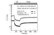
- FIG. 1 shows the dynamic viscoelasticity measurement result of the photosensitive composite material 1.
- the photosensitive composite material 1 is installed in a dynamic viscoelasticity measuring apparatus (Anton Paar Japan Co., Ltd., MCR302), using a parallel plate with a diameter of 8 mm, a gap of 500 ⁇ m, a temperature of 25 ° C., a strain of 0.1%, and a frequency of 1.0 Hz.
- the dynamic viscoelasticity was evaluated under the following conditions.
- the glass transition temperature was 38.3 ° C.
- the storage elastic modulus G ′ and the loss elastic modulus G ′′ as indices of hardness were 2.4 ⁇ 10 5 Pa and 4.0 ⁇ 10 5 Pa, respectively.
- the glass transition temperature of the photosensitive composite material 1 was 21.6 ° C.
- the storage elastic modulus G ′ was 3.8 ⁇ 10 4 Pa
- the loss elastic modulus G. Became 2.3 ⁇ 10 4 Pa (total irradiation energy 78 J / cm 2 ), and it was confirmed that the glass transition temperature of the photosensitive composite material 1 changed and became soft.
- the storage elastic modulus G ′ was 1.2 ⁇ 10 5 Pa and the loss elastic modulus G "Became 1.2 ⁇ 10 5 Pa (total irradiation energy 108 J / cm 2 ). From this result, the hardness of the photosensitive composite material 1 was reversibly controlled by irradiation with ultraviolet light and visible light. I was able to confirm that
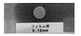
- FIG. 2 shows the appearance of a film produced using the photosensitive composite material 1.
- FIG. 3 shows the result of the tensile shear test of the photosensitive composite material 1.
- a film of photosensitive composite material 1 was produced in the same manner as described above.
- the film was sandwiched between two glass substrates, heated at 60 ° C. for 3 minutes, and then cooled to room temperature to prepare Sample A having an adhesion area of 1 cm 2 .
- Sample A was installed in a tensile tester (ORIENTEC, TENSILON), and the tensile shear strength of the sample A in the bonded state was evaluated at a temperature of 24.4 ° C. and a tensile speed of 8.3 ⁇ m per second. As shown in “Initial” in FIG. 3, the tensile shear strength of Sample A was 0.30 MPa.
- a separately prepared film of photosensitive composite material 1 having an area of 1 cm 2 and a thickness of 0.08 mm was placed on a glass substrate, and irradiated with ultraviolet light having a wavelength of 365 nm and an irradiation energy of 54 J / cm 2 at 25 ° C. And about the sample B which pressed and adhered another glass substrate at 25 degreeC, it carried out similarly to the above, and measured the tensile shear strength. As shown by “UV” in FIG. 3, the tensile shear strength of the sample B in an adhesive state was 0.01 MPa.
- a separately prepared film of photosensitive composite material 1 having an area of 1 cm 2 and a thickness of 0.08 mm was placed on a glass substrate, and irradiated with ultraviolet light having a wavelength of 365 nm and an irradiation energy of 54 J / cm 2 at 25 ° C. Then, another glass substrate was pressed and adhered at 25 ° C., and further, visible light having a wavelength of 450 nm and an irradiation energy of 45 J / cm 2 was irradiated at 25 ° C. to produce a sample C in an adhesive state with an adhesion area of 1 cm 2. did.
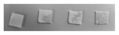
- FIG. 4 shows how the photosensitive composite material 1 is self-repaired.
- a film of the photosensitive composite material 1 having a length of 9 mm, a width of 5 mm, and a thickness of 1 mm was produced in the same manner as described above.
- this film was cut into two at the center using a cutter knife. Thereafter, the cut pieces were brought into contact with each other and irradiated with ultraviolet light having a wavelength of 365 nm and an irradiation energy of 60 J / cm 2 , and it was confirmed that the cut surfaces of the pieces were self-repaired and integrated.
- test piece of photosensitive composite material 1 used for natural restoration of dents A test piece was prepared using the photosensitive composite material 1 in the following procedure. First, the photosensitive composite material 1 and a glass spacer having a thickness of 1 mm were placed on a slide glass. Thereafter, the photosensitive composite material was heated to 60 ° C. to make it soft. Next, another glass slide was placed on the soft light-sensitive composite material 1 and the glass spacer, and the light-sensitive composite material 1 and the glass slide were sandwiched between two glass slides, and pressure was applied uniformly. And after cooling the photosensitive composite material 1 to room temperature, the photosensitive composite material 1 was peeled from the slide glass, and the photosensitive composite material film was obtained. The obtained film was cut into a circle having a radius of 4 mm with a cutter knife to obtain a test piece for a strain repair property test.
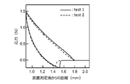
- FIG. 5 shows the results of evaluating the dent repair characteristics of the photosensitive composite material 1 using a dynamic viscoelasticity measuring apparatus (Anton Paar Japan, MCR302). Place the test piece on the dynamic viscoelasticity measuring device, and use a minus driver type jig with a contact area of 0.05 cm 2 , and use a minus driver type jig at a temperature of 25 ° C., a strain of 0%, and a frequency of 0 Hz. The gap between the tip and the apparatus measurement surface was narrowed, and the photosensitive composite material 1 was deformed until the gap value became 0.9 mm (test 1). As shown in test 1 of FIG. 5, the value of the gap at which the flat screwdriver jig comes into contact with the photosensitive composite material 1 and stress is generated was 1.8 mm.
- test 2 the gap value at which the jig was brought into contact with the photosensitive composite material and the stress was generated was 1.8 mm, which was the same as in test 1. This indicates that the dent produced by pushing in the flat-blade screwdriver jig has been restored to its original state in 30 minutes, and the dent produced on the surface of the photosensitive composite material 1 is naturally restored. It was confirmed.
- Photosensitive composite material 2 (Preparation of photosensitive composite material 2) Except for changing the weight of polymethyl methacrylate, 4-cyano-4'-pentylbiphenyl, and 4-butyl-4'-methoxyazobenzene to 0.50 g, 0.475 g, and 0.025 g, respectively, Photosensitive composite material 2 was prepared in the same manner as in Example 1.
- the photosensitive composite material 2 contains 50% by mass of polymethyl methacrylate, 47.5% by mass of 4-cyano-4′-pentylbiphenyl, and 2.5% by mass of 4-butyl-4′-methoxyazobenzene. It is.
- FIG. 6 shows the dynamic viscoelasticity measurement result of the photosensitive composite material 2.
- the photosensitive composite material 2 had a glass transition temperature of 38.3 ° C., a storage elastic modulus G ′ of 7.4 ⁇ 10 5 Pa, and a loss elastic modulus G ′′ of 1.3 ⁇ 10 6 Pa.
- the storage elastic modulus G ′ was 3.4 ⁇ 10 5 Pa and the loss elastic modulus G ′′ was 4.8 ⁇ 10 5 Pa.
- Total irradiation energy 90 J / cm 2 it was confirmed that the photosensitive composite material 2 became soft.
- the glass transition temperature was 28.2 ° C. and the storage elastic modulus G ′ was 4.5. ⁇ 10 5 Pa
- loss elastic modulus G ′′ was 7.0 ⁇ 10 5 Pa (total irradiation energy 63 J / cm 2 )
- the photosensitive composite material 2 became hard. From this result, ultraviolet light and visible light It was confirmed that the hardness of the photosensitive composite material 2 can be reversibly controlled by irradiation.
- FIG. 7 shows the appearance of a film produced using the photosensitive composite material 2.
- FIG. 8 shows the result of the tensile shear test of the photosensitive composite material 2.
- a film of photosensitive composite material 2 was produced in the same manner as described above. Next, this film was sandwiched between two glass substrates, heated at 60 ° C. for 3 minutes, and then cooled to room temperature to prepare Sample D having an adhesion area of 0.25 cm 2 .
- Sample D was evaluated for tensile shear strength in the same manner as in Example 1. As shown in “Initial” in FIG. 8, the tensile shear strength of Sample D was 0.57 MPa.
- a separately prepared film of photosensitive composite material 2 having an area of 0.25 cm 2 and a thickness of 0.12 mm is placed on a glass substrate, and irradiated at 25 ° C. with ultraviolet light having a wavelength of 365 nm and an irradiation energy of 54 J / cm 2. did.
- the sample E which pressed and adhered another glass substrate at 25 degreeC it carried out similarly to the above, and measured the tensile shear strength. As shown in “UV” in FIG. 8, the tensile shear strength of the sample E in an adhesive state was 0.26 MPa.
- a separately prepared film of photosensitive composite material 2 having an area of 0.25 cm 2 and a thickness of 0.12 mm is placed on a glass substrate, and ultraviolet light having a wavelength of 365 nm and an irradiation energy of 54 J / cm 2 is applied at 25 ° C. After irradiation, another glass substrate was pressed and adhered at 25 ° C., and further, irradiated with visible light having a wavelength of 450 nm and an irradiation energy of 45 J / cm 2 at 25 ° C., and an adhesion state of 0.25 cm 2 was obtained. Sample F was prepared.
- a photosensitive composite material 3 was prepared in the same manner as in Example 1.
- the photosensitive composite material 3 contains 60% by mass of polymethyl methacrylate, 38% by mass of 4-cyano-4′-pentylbiphenyl, and 2% by mass of 4-butyl-4′-methoxyazobenzene.
- FIG. 9 shows the dynamic viscoelasticity measurement result of the photosensitive composite material 3.
- the storage elastic modulus G ′ of the light-sensitive composite material 3 immediately after preparation was 1.9 ⁇ 10 6 Pa and the loss elastic modulus G ′′ was 3.2 ⁇ 10 6 Pa.
- ultraviolet light having a wavelength of 365 nm was measured while irradiating the photosensitive composite material 3, and the storage elastic modulus G ′ was 1.0 ⁇ 10 6 Pa and the loss elastic modulus G ′′ was 1.9 ⁇ 10 6 Pa (total irradiation energy 63 J / cm 2 ) It was confirmed that the photosensitive composite material 3 became soft.
- the storage elastic modulus G ′ was 1.5 ⁇ 10 6 Pa and the loss elastic modulus G ”Became hard at 2.7 ⁇ 10 6 Pa (total irradiation energy 54 J / cm 2 ). From this result, the hardness of the photosensitive composite material 3 was reversibly controlled by irradiation with ultraviolet light and visible light. I was able to confirm that it was possible.
- FIG. 10 shows the appearance of a film produced using the photosensitive composite material 3.
- the light transmittance of this film showed a high value of 90% or more in the wavelength range of 550 nm to 800 nm in the visible light region.
- FIG. 11 shows the result of the tensile shear test of the photosensitive composite material 3.
- a film of photosensitive composite material 3 was produced in the same manner as described above. Next, this film was sandwiched between two glass substrates, heated at 60 ° C. for 3 minutes, and then cooled to room temperature to prepare a sample G having an adhesion area of 0.25 cm 2 .
- the tensile shear strength was evaluated in the same manner as in Example 1. As shown in “Initial” in FIG. 11, the tensile shear strength of the sample G was 1.63 MPa.
- a separately prepared film of photosensitive composite material 3 having an area of 0.25 cm 2 and a thickness of 0.25 mm is placed on a glass substrate, and irradiated at 25 ° C. with ultraviolet light having a wavelength of 365 nm and an irradiation energy of 54 J / cm 2. did.
- the sample H which pressed and adhered another glass substrate at 25 degreeC it carried out similarly to the above, and measured the tensile shear strength. As shown in “UV” in FIG. 11, the tensile shear strength of the adhesive sample H was 0.30 MPa.
- a separately prepared film of photosensitive composite material 3 having an area of 0.25 cm 2 and a thickness of 0.25 mm is placed on a glass substrate, and ultraviolet light having a wavelength of 365 nm and an irradiation energy of 54 J / cm 2 is applied at 25 ° C. After irradiation, another glass substrate was pressed and adhered at 25 ° C., and further, irradiated with visible light having a wavelength of 450 nm and an irradiation energy of 45 J / cm 2 at 25 ° C., and an adhesion state of 0.25 cm 2 was obtained. Sample I was prepared.
- a film of photosensitive composite material 3 having a thickness of 0.05 mm was produced on a slide glass.
- the film was peeled off from the slide glass, adhered onto a commercially available artificial nail made of methacrylic resin, and shaped according to the shape of the artificial nail.
- ultraviolet light having a wavelength of 365 nm and a light intensity of 150 mW / cm 2 is irradiated on the film for 300 seconds (irradiation energy is 45 J / cm 2 ), and the film of the photosensitive composite material 3 is transferred onto the artificial nail surface. did.
- the film of the photosensitive composite material 3 transferred to the artificial nail surface is shown in FIG.
- the film was further irradiated with ultraviolet light for 300 seconds (irradiation energy was 45 J / cm 2 ) to soften the film, and six commercially available acrylic resin stones, which are nail parts, were pressed and adhered. .
- the film was irradiated with visible light having a wavelength of 450 nm and a light intensity of 100 mW / cm 2 at 25 ° C. for 300 seconds (irradiation energy was 30 J / cm 2 ), the film was cured to be in an adhesive state, and a nail part was attached. I attached.
- the nail part was able to be detached from the film of the photosensitive composite material 3 by applying a stress of 1 MPa to the nail part.
- the entire film is irradiated with ultraviolet light having a wavelength of 365 nm and a light intensity of 150 mW / cm 2 for 300 seconds (irradiation energy is 45 J / cm 2 ) to soften the film.
- irradiation energy is 45 J / cm 2
- the light-sensitive composite material of the present invention can be used for adhesive bonding and painting in a wide range of fields such as fishing bait, construction, transport machinery, electronics, medicine, and space.
- seat and film comprised from the photosensitive composite material of this invention can be used for cosmetics, such as an adhesive agent for nail art.
Landscapes
- Chemical & Material Sciences (AREA)
- Organic Chemistry (AREA)
- Health & Medical Sciences (AREA)
- Chemical Kinetics & Catalysis (AREA)
- Medicinal Chemistry (AREA)
- Polymers & Plastics (AREA)
- Engineering & Computer Science (AREA)
- Manufacturing & Machinery (AREA)
- Materials Engineering (AREA)
- Adhesives Or Adhesive Processes (AREA)
- Manufacture Of Macromolecular Shaped Articles (AREA)
- Compositions Of Macromolecular Compounds (AREA)
- Adhesive Tapes (AREA)
Abstract
Description
高分子化合物であるポリメタクリル酸メチル(和光純薬工業株式会社製、138-02735、重量平均分子量は約10万)0.40g、液晶化合物である4-シアノ-4’-ペンチルビフェニル(メルク・ジャパン株式会社製、K-15)0.57g、光応答性化合物である4-ブチル-4’-メトキシアゾベンゼン0.030gをアセトン10mLに溶解し、40℃で撹拌して均一な溶液とした後、60℃でアセトンを減圧留去して光感応性複合材料1を調製した。光感応性複合材料1には、ポリメタクリル酸メチルが40質量%、4-シアノ-4’-ペンチルビフェニルが57質量%、4-ブチル-4’-メトキシアゾベンゼンが3質量%含まれている。
図1は光感応性複合材料1の動的粘弾性測定結果を示している。光感応性複合材料1を動的粘弾性測定装置(アントンパールジャパン社、MCR302)に設置し、直径8mmのパラレルプレートを用い、ギャップ500μm、温度25℃、歪み0.1%、周波数1.0Hzの条件で動的粘弾性を評価した。ガラス転移温度は38.3℃であり、硬さの指標となる貯蔵弾性率G’および損失弾性率G”は、それぞれ2.4×10⁵Paおよび4.0×10⁵Paであった。つぎに、光感応性複合材料1に波長365nmの紫外光を照射しながら測定したところ、ガラス転移温度が21.6℃、貯蔵弾性率G’が3.8×10⁴Pa、損失弾性率G” が2.3×10⁴Paとなり(総照射エネルギー78J/cm2)、光感応性複合材料1のガラス転移温度が変化して軟らかくなることを確認した。
以下の手順で光感応性複合材料1を用いてフィルムを作製した。まず、光感応性複合材料1と厚さ0.12mmのステンレスフィルムスペーサーをスライドガラス上に設置した後、光感応性複合材料1を60℃に加熱して軟らかい状態にした。つぎに、この軟らかい光感応性複合材料1とステンレスフィルムスペーサーの上から他のスライドガラスを設置し、光感応性複合材料1とステンレスフィルムスペーサーを2枚のスライドガラスで挟んで均一に圧力を加えた。そして、光感応性複合材料1を室温まで冷却した後、スライドガラスから光感応性複合材料1を剥離して、光感応性複合材料フィルムを得た。図2は、光感応性複合材料1を用いて作製したフィルムの外観を示している。
図3は、光感応性複合材料1の引張せん断試験の結果を示している。厚さ0.08mmのポリエチレンフィルムスペーサーを用いて、上記手順と同様にして光感応性複合材料1のフィルムを作製した。つぎに、このフィルムを2枚のガラス基板で挟み、60℃で3分間加熱した後、室温に冷却して接着面積1cm2の試料Aを作製した。試料Aを引張試験機(ORIENTEC社、TENSILON)に設置し、温度24.4℃、毎秒8.3μmの引張速度で、接着状態の試料Aの引張せん断強度を評価した。図3の「Initial」に示すように、試料Aの引張せん断強度は0.30MPaであった。
図4は、光感応性複合材料1の自己修復の様子を示している。まず、厚さ1mmのガラススペーサーを用い、上記手順と同様にして、縦9mm×横5mm×厚さ1mmの光感応性複合材料1のフィルムを作製した。つぎに、カッターナイフを用いてこのフィルムを中央で二つに切断した。その後、切断した小片同士を接触させて、波長365nm、照射エネルギー60J/cm2の紫外光をこの接触部に照射したところ、小片の切断面が自己修復されて一体化することを確認した。
以下の手順で光感応性複合材料1を用いて試験片を作製した。まず、光感応性複合材料1と厚さ1mmのガラススペーサーをスライドガラス上に設置した。その後、光感応性複合材料を60℃に加熱して軟らかい状態にした。つぎに、この軟らかい光感応性複合材料1とガラススペーサーの上から他のスライドガラスを設置し、光感応性複合材料1とスライドガラスを2枚のスライドガラスで挟んで均一に圧力を加えた。そして、光感応性複合材料1を室温まで冷却した後、スライドガラスから光感応性複合材料1を剥離して、光感応性複合材料フィルムを得た。得られたフィルムをカッターナイフで半径4mmの円形に切断し、歪み修復特性試験の試験片を得た。
図5は、動的粘弾性測定装置(アントンパールジャパン社、MCR302)を用いて、光感応性複合材料1の凹み修復特性を評価した結果を示している。試験片を動的粘弾性測定装置に設置し、接触面積が0.05cm2であるマイナスドライバー型の治具を用い、温度25℃、歪み0%、周波数0Hzの条件でマイナスドライバー型治具の先端と装置測定面とのギャップを狭めていき、ギャップ値が0.9mmとなるまで光感応性複合材料1に変形を加えた(test1)。図5のtest1に示すように、マイナスドライバー型治具が光感応性複合材料1と接触し、応力が発生するギャップの値は1.8mmであった。
ポリメタクリル酸メチル、4-シアノ-4’-ペンチルビフェニル、および4-ブチル-4’-メトキシアゾベンゼンの質量を、それぞれ0.50g、0.475g、および0.025gに変更した点を除いて、実施例1と同様にして光感応性複合材料2を調製した。光感応性複合材料2には、ポリメタクリル酸メチルが50質量%、4-シアノ-4’-ペンチルビフェニルが47.5質量%、4-ブチル-4’-メトキシアゾベンゼンが2.5質量%含まれている。
実施例1と同様にして光感応性複合材料2の動的粘弾性を評価した。図6は光感応性複合材料2の動的粘弾性測定結果を示している。光感応性複合材料2のガラス転移温度は38.3℃で、貯蔵弾性率G’は7.4×10⁵Paで、損失弾性率G”は1.3×10⁶Paであった。つぎに、波長365nmの紫外光を光感応性複合材料2に照射しながら測定したところ、貯蔵弾性率G’が3.4×10⁵Pa、損失弾性率G” が4.8×10⁵Paとなり(総照射エネルギー90J/cm2)、光感応性複合材料2が軟らかくなることを確認した。
以下の手順で光感応性複合材料2を用いてフィルムを作製した。まず、光感応性複合材料2と厚さ0.05mmのポリエチレンフィルムスペーサーをスライドガラス上に設置した後、光感応性複合材料2を60℃に加熱して軟らかい状態にした。つぎに、軟らかい光感応性複合材料2とポリエチレンフィルムスペーサーの上から他のスライドガラスを設置し、光感応性複合材料1とポリエチレンフィルムスペーサーを2枚のスライドガラスで挟んで均一に圧力を加えた。そして、光感応性複合材料2を室温まで冷却した後、スライドガラスから光感応性複合材料2を剥離して、光感応性複合材料フィルムを得た。図7は、光感応性複合材料2を用いて作製したフィルムの外観を示している。
図8は、光感応性複合材料2の引張せん断試験の結果を示している。厚さ0.12mmのポリエチレンフィルムスペーサーを用いて、上記手順と同様にして光感応性複合材料2のフィルムを作製した。つぎに、このフィルムを2枚のガラス基板で挟み、60℃で3分間加熱した後、室温に冷却して接着面積0.25cm2の試料Dを作製した。試料Dについて、実施例1と同様にして引張せん断強度を評価した。図8の「Initial」に示すように、試料Dの引張せん断強度は0.57MPaであった。
ポリメタクリル酸メチル、4-シアノ-4’-ペンチルビフェニル、および4-ブチル-4’-メトキシアゾベンゼンの質量を、それぞれ0.60g、0.38g、および0.020gに変更した点を除いて、実施例1と同様にして光感応性複合材料3を調製した。光感応性複合材料3には、ポリメタクリル酸メチルが60質量%、4-シアノ-4’-ペンチルビフェニルが38質量%、4-ブチル-4’-メトキシアゾベンゼンが2質量%含まれている。
実施例1と同様にして光感応性複合材料3の動的粘弾性を評価した。図9は光感応性複合材料3の動的粘弾性測定結果を示している。調製直後の光感応性複合材料3の貯蔵弾性率G’は1.9×10⁶Paで、損失弾性率G”は3.2×10⁶Paであった。つぎに、波長365nmの紫外光を光感応性複合材料3に照射しながら測定したところ、貯蔵弾性率G’が1.0×10⁶Pa、損失弾性率G” が1.9×10⁶Paとなり(総照射エネルギー63J/cm2)、光感応性複合材料3が軟らかくなることを確認した。
実施例2と同様の手順で光感応性複合材料3を用いてフィルムを作製した。この結果、透明なフィルムが得られた。図10は、光感応性複合材料3を用いて作製したフィルムの外観を示している。このフィルムの光透過率は、可視光領域のうち波長550nm~800nmの範囲で90%以上の高い値を示した。
図11は、光感応性複合材料3の引張せん断試験の結果を示している。厚さ0.25mmのポリエチレンフィルムスペーサーを用いて、上記手順と同様にして光感応性複合材料3のフィルムを作製した。つぎに、このフィルムを2枚のガラス基板で挟み、60℃で3分間加熱した後、室温に冷却して接着面積0.25cm2の試料Gを作製した。試料Gについて、実施例1と同様にして引張せん断強度を評価した。図11の「Initial」に示すように、試料Gの引張せん断強度は1.63MPaであった。
まず、厚さ0.05mmの光感応性複合材料3のフィルムをスライドガラス上で作製した。つぎに、スライドガラスからこのフィルムを剥離し、市販のメタクリル樹脂製の人工爪の上に密着させ、人工爪の形に合わせて整形した。そして、25℃で、波長365nm、光強度150mW/cm2の紫外光をこのフィルムに300秒間照射し(照射エネルギーは45J/cm2)、人工爪表面に光感応性複合材料3のフィルムを転写した。人工爪表面に転写された光感応性複合材料3のフィルムを図12に示す。
Claims (11)
- 高分子化合物と、
前記高分子化合物中に粒状で分散している液晶化合物と、
異なる波長の光の照射によって分子形状が可逆的に変化する光応答性化合物と、
を含有する光感応性複合材料。 - 請求項1において、
前記高分子化合物の溶解度パラメーターと前記液晶化合物の溶解度パラメーターとの差が10以内である光感応性複合材料。 - 請求項1または2において、
前記光応答性化合物がアゾベンゼン誘導体である光感応性複合材料。 - 請求項1から3のいずれかにおいて、
前記高分子化合物の質量が全体の質量の40%~60%である光感応性複合材料。 - 請求項1から4のいずれかにおいて、
前記液晶化合物の質量と前記光応答性化合物の質量の和に対する前記光応答性化合物の質量が2%~100%である光感応性複合材料。 - 請求項1から5のいずれかにおいて、
前記異なる波長の光が紫外光と可視光であり、
紫外光照射によってガラス転移温度が降下し、紫外光照射によって降下したガラス転移温度が可視光照射によって上昇する光感応性複合材料。 - 請求項1から6のいずれかの光感応性複合材料をフィルム状に成形した光感応性複合材料フィルム。
- 請求項7において、
装飾品を爪に貼り付けるための接着フィルムである光感応性複合材料フィルム。 - 高分子化合物と、前記高分子化合物中に粒状で分散している液晶化合物と、異なる波長の光の照射によって分子形状が可逆的に変化する光応答性化合物とを含有する光感応性複合材料の製造方法であって、
前記高分子化合物と、前記液晶化合物と、前記光応答性化合物とを揮発性の有機溶媒に溶解する溶解工程と、
前記溶解工程の後、前記有機溶媒を除去する溶媒除去工程と、
を有する光感応性複合材料の製造方法。 - 高分子化合物と、前記高分子化合物中に粒状で分散している液晶化合物と、紫外光と可視光の照射によって分子形状が可逆的に変化する光応答性化合物とを含有する光感応性複合材料の損傷部位または切断部位の修復方法であって、
前記光感応性複合材料の損傷部位または切断部位に紫外光を照射して、前記損傷部位を軟化または前記切断部位を粘着させる復元工程と、
前記復元工程の後、前記損傷部位または前記切断部位に可視光を照射して、前記損傷部位または前記切断部位を硬化させる硬化工程と、
を有する光感応性複合材料の損傷部位または切断部位の修復方法。 - 高分子化合物と、前記高分子化合物中に粒状で分散している液晶化合物と、紫外光と可視光の照射によって分子形状が可逆的に変化する光応答性化合物とを含有する光感応性複合材料フィルムの使用方法であって、
前記光感応性複合材料フィルムに紫外光を照射して、前記光感応性複合材料フィルムを軟化させる軟化工程と、
軟化した前記光感応性複合材料フィルムを、被接着物に押し付ける押圧工程と、
前記被接着物に押し付けられた前記光感応性複合材料フィルムに接着物を貼り付ける貼付工程と、
前記貼付工程の後、前記光感応性複合材料フィルムに可視光を照射して、前記光感応性複合材料フィルムを硬化させる硬化工程と、
を有する光感応性複合材料フィルムの使用方法。
Priority Applications (3)
| Application Number | Priority Date | Filing Date | Title |
|---|---|---|---|
| JP2016571995A JP6449340B2 (ja) | 2015-01-27 | 2016-01-22 | 光感応性複合材料とその製造方法、および光感応性複合材料フィルムの使用方法 |
| CN201680003233.4A CN107075263B (zh) | 2015-01-27 | 2016-01-22 | 光感应性复合材料和其制造方法、及光感应性复合材料膜的使用方法 |
| KR1020177008765A KR101958583B1 (ko) | 2015-01-27 | 2016-01-22 | 광감응성 복합재료와 그 제조방법, 및 광감응성 복합재료 필름의 사용방법 |
Applications Claiming Priority (4)
| Application Number | Priority Date | Filing Date | Title |
|---|---|---|---|
| JP2015-013499 | 2015-01-27 | ||
| JP2015013499 | 2015-01-27 | ||
| JP2015129091 | 2015-06-26 | ||
| JP2015-129091 | 2015-06-26 |
Publications (1)
| Publication Number | Publication Date |
|---|---|
| WO2016121651A1 true WO2016121651A1 (ja) | 2016-08-04 |
Family
ID=56543264
Family Applications (1)
| Application Number | Title | Priority Date | Filing Date |
|---|---|---|---|
| PCT/JP2016/051877 Ceased WO2016121651A1 (ja) | 2015-01-27 | 2016-01-22 | 光感応性複合材料とその製造方法、および光感応性複合材料フィルムの使用方法 |
Country Status (4)
| Country | Link |
|---|---|
| JP (1) | JP6449340B2 (ja) |
| KR (1) | KR101958583B1 (ja) |
| CN (1) | CN107075263B (ja) |
| WO (1) | WO2016121651A1 (ja) |
Cited By (4)
| Publication number | Priority date | Publication date | Assignee | Title |
|---|---|---|---|---|
| JP2018048814A (ja) * | 2016-09-20 | 2018-03-29 | 国立研究開発法人産業技術総合研究所 | 受光応答装置 |
| JP2018119137A (ja) * | 2017-01-23 | 2018-08-02 | 国立研究開発法人産業技術総合研究所 | 高分子化合物用硬さ調整剤及び光感応性複合材料 |
| WO2020213641A1 (ja) * | 2019-04-19 | 2020-10-22 | 国立研究開発法人産業技術総合研究所 | 光応答性ポリビニルエーテル化合物および光可逆接着剤 |
| WO2020255579A1 (ja) * | 2019-06-21 | 2020-12-24 | 国立研究開発法人産業技術総合研究所 | 高分子化合物用剥離剤、接着材料及び接着材料の使用方法 |
Families Citing this family (4)
| Publication number | Priority date | Publication date | Assignee | Title |
|---|---|---|---|---|
| CN109652000B (zh) * | 2018-12-21 | 2021-08-31 | 广州市白云化工实业有限公司 | 一种新型电子印刷电路板披覆胶及其制备方法 |
| CN109666438B (zh) * | 2018-12-21 | 2020-09-01 | 广州市白云化工实业有限公司 | 光响应性粘结胶及其制备方法 |
| CN112048279B (zh) * | 2020-09-11 | 2022-04-26 | 为远材料科技(辽宁)有限责任公司 | 光释放胶及其制备方法和石墨烯的转移方法 |
| CN113912543B (zh) * | 2021-10-11 | 2022-12-23 | 上海交通大学 | 一种基于吡唑基偶氮苯胺的光控小分子粘合剂 |
Citations (10)
| Publication number | Priority date | Publication date | Assignee | Title |
|---|---|---|---|---|
| JPH01225924A (ja) * | 1988-03-07 | 1989-09-08 | Rikagaku Kenkyusho | 高分子複合膜 |
| JP2001242319A (ja) * | 2000-02-29 | 2001-09-07 | Fuji Photo Film Co Ltd | 光学フイルム、偏光板および液晶表示装置 |
| JP2002169016A (ja) * | 2000-11-30 | 2002-06-14 | Fuji Photo Film Co Ltd | 光学フイルム、偏光素子、偏光素子の製造方法、偏光板および液晶表示装置 |
| JP2002179682A (ja) * | 2000-12-15 | 2002-06-26 | Fuji Photo Film Co Ltd | 光学活性化合物、光反応型キラル剤、液晶組成物、液晶カラーフィルタ、光学フィルム及び記録媒体、並びに液晶の螺旋構造を変化させる方法、液晶の螺旋構造を固定化する方法 |
| JP2002309103A (ja) * | 2001-04-13 | 2002-10-23 | Fuji Photo Film Co Ltd | 液晶性組成物、カラーフィルタ、及び液晶表示装置 |
| JP2003238962A (ja) * | 2002-02-21 | 2003-08-27 | Takashi Kato | 光応答性液晶組成物、情報記録媒体および情報記録方法 |
| JP2008020538A (ja) * | 2006-07-11 | 2008-01-31 | Fuji Xerox Co Ltd | ホログラム記録材料、ホログラム記録媒体およびホログラム記録方法 |
| JP2013144769A (ja) * | 2011-05-27 | 2013-07-25 | National Institute Of Advanced Industrial Science & Technology | 自己修復性材料、自己修復性材料の使用方法及びゲル材料 |
| WO2015022895A1 (ja) * | 2013-08-14 | 2015-02-19 | 国立大学法人東京工業大学 | 光配向材料および光配向方法 |
| JP2015218249A (ja) * | 2014-05-16 | 2015-12-07 | 国立研究開発法人産業技術総合研究所 | ゲル材料、ゲル材料の製造方法及びゲル材料の使用方法 |
Family Cites Families (9)
| Publication number | Priority date | Publication date | Assignee | Title |
|---|---|---|---|---|
| AU2001227110A1 (en) * | 2000-01-27 | 2001-08-07 | Fuji Photo Film Co. Ltd. | Sheet polarizer on which light-scattering polarizing element and light-absorption polarizing element are provided in multiyear |
| JP2005281504A (ja) * | 2004-03-30 | 2005-10-13 | Takashi Kato | 光応答性液晶組成物 |
| JP5151419B2 (ja) | 2007-11-28 | 2013-02-27 | 東亞合成株式会社 | 光硬化型粘接着剤製造用の光硬化型組成物及び光硬化型粘接着シート |
| JP5376565B2 (ja) * | 2008-06-11 | 2013-12-25 | 独立行政法人産業技術総合研究所 | 光応答性液晶材料 |
| JP5618272B2 (ja) * | 2010-05-10 | 2014-11-05 | 独立行政法人産業技術総合研究所 | 光応答性液晶化合物およびその応用 |
| JP5652617B2 (ja) | 2011-04-27 | 2015-01-14 | 大日本印刷株式会社 | 熱硬化型粘接着剤組成物、粘接着シート、及び粘接着シートの製造方法 |
| WO2013081155A1 (ja) * | 2011-12-01 | 2013-06-06 | 独立行政法人産業技術総合研究所 | 感光性アゾベンゼン誘導体 |
| WO2013168712A1 (ja) * | 2012-05-07 | 2013-11-14 | 独立行政法人産業技術総合研究所 | 光応答性接着剤 |
| JP6502665B2 (ja) * | 2014-12-26 | 2019-04-17 | 国立研究開発法人産業技術総合研究所 | 複合材料、複合材料用組成物、複合材料の製造方法及び複合材料の使用方法 |
-
2016
- 2016-01-22 CN CN201680003233.4A patent/CN107075263B/zh not_active Expired - Fee Related
- 2016-01-22 WO PCT/JP2016/051877 patent/WO2016121651A1/ja not_active Ceased
- 2016-01-22 KR KR1020177008765A patent/KR101958583B1/ko not_active Expired - Fee Related
- 2016-01-22 JP JP2016571995A patent/JP6449340B2/ja not_active Expired - Fee Related
Patent Citations (10)
| Publication number | Priority date | Publication date | Assignee | Title |
|---|---|---|---|---|
| JPH01225924A (ja) * | 1988-03-07 | 1989-09-08 | Rikagaku Kenkyusho | 高分子複合膜 |
| JP2001242319A (ja) * | 2000-02-29 | 2001-09-07 | Fuji Photo Film Co Ltd | 光学フイルム、偏光板および液晶表示装置 |
| JP2002169016A (ja) * | 2000-11-30 | 2002-06-14 | Fuji Photo Film Co Ltd | 光学フイルム、偏光素子、偏光素子の製造方法、偏光板および液晶表示装置 |
| JP2002179682A (ja) * | 2000-12-15 | 2002-06-26 | Fuji Photo Film Co Ltd | 光学活性化合物、光反応型キラル剤、液晶組成物、液晶カラーフィルタ、光学フィルム及び記録媒体、並びに液晶の螺旋構造を変化させる方法、液晶の螺旋構造を固定化する方法 |
| JP2002309103A (ja) * | 2001-04-13 | 2002-10-23 | Fuji Photo Film Co Ltd | 液晶性組成物、カラーフィルタ、及び液晶表示装置 |
| JP2003238962A (ja) * | 2002-02-21 | 2003-08-27 | Takashi Kato | 光応答性液晶組成物、情報記録媒体および情報記録方法 |
| JP2008020538A (ja) * | 2006-07-11 | 2008-01-31 | Fuji Xerox Co Ltd | ホログラム記録材料、ホログラム記録媒体およびホログラム記録方法 |
| JP2013144769A (ja) * | 2011-05-27 | 2013-07-25 | National Institute Of Advanced Industrial Science & Technology | 自己修復性材料、自己修復性材料の使用方法及びゲル材料 |
| WO2015022895A1 (ja) * | 2013-08-14 | 2015-02-19 | 国立大学法人東京工業大学 | 光配向材料および光配向方法 |
| JP2015218249A (ja) * | 2014-05-16 | 2015-12-07 | 国立研究開発法人産業技術総合研究所 | ゲル材料、ゲル材料の製造方法及びゲル材料の使用方法 |
Cited By (7)
| Publication number | Priority date | Publication date | Assignee | Title |
|---|---|---|---|---|
| JP2018048814A (ja) * | 2016-09-20 | 2018-03-29 | 国立研究開発法人産業技術総合研究所 | 受光応答装置 |
| JP2018119137A (ja) * | 2017-01-23 | 2018-08-02 | 国立研究開発法人産業技術総合研究所 | 高分子化合物用硬さ調整剤及び光感応性複合材料 |
| WO2020213641A1 (ja) * | 2019-04-19 | 2020-10-22 | 国立研究開発法人産業技術総合研究所 | 光応答性ポリビニルエーテル化合物および光可逆接着剤 |
| JPWO2020213641A1 (ja) * | 2019-04-19 | 2021-12-09 | 国立研究開発法人産業技術総合研究所 | 光応答性ポリビニルエーテル化合物および光可逆接着剤 |
| JP7129729B2 (ja) | 2019-04-19 | 2022-09-02 | 国立研究開発法人産業技術総合研究所 | 光応答性ポリビニルエーテル化合物および光可逆接着剤 |
| WO2020255579A1 (ja) * | 2019-06-21 | 2020-12-24 | 国立研究開発法人産業技術総合研究所 | 高分子化合物用剥離剤、接着材料及び接着材料の使用方法 |
| JP2021001262A (ja) * | 2019-06-21 | 2021-01-07 | 国立研究開発法人産業技術総合研究所 | 高分子化合物用剥離剤、接着材料及び接着材料の使用方法 |
Also Published As
| Publication number | Publication date |
|---|---|
| KR20170049552A (ko) | 2017-05-10 |
| CN107075263A (zh) | 2017-08-18 |
| CN107075263B (zh) | 2020-06-30 |
| JPWO2016121651A1 (ja) | 2017-08-03 |
| JP6449340B2 (ja) | 2019-01-09 |
| KR101958583B1 (ko) | 2019-03-14 |
Similar Documents
| Publication | Publication Date | Title |
|---|---|---|
| JP6449340B2 (ja) | 光感応性複合材料とその製造方法、および光感応性複合材料フィルムの使用方法 | |
| CN104419331B (zh) | 光固化性粘接剂组合物、偏光板及其制造方法、光学构件以及液晶显示装置 | |
| JP6810054B2 (ja) | アクリルポリマーに基づくuv硬化性接着剤 | |
| TWI460245B (zh) | An adhesive composition and a method using its temporary fixing member | |
| CN102471508B (zh) | 丙烯酸薄膜的制备方法及丙烯酸薄膜 | |
| CN104745104B (zh) | 光固化性粘接剂组合物、偏光板及其制造方法、光学构件以及液晶显示装置 | |
| TWI595037B (zh) | 硬化性樹脂組成物、接著劑組成物、硬化體或複合體 | |
| TWI753461B (zh) | 高分子化合物用剝離劑、接著材料及接著材料之使用方法 | |
| Czech et al. | Development of solvent-free acrylic pressure-sensitive adhesives | |
| JP2013542455A5 (ja) | ||
| JP2018524426A5 (ja) | ||
| JP2010275373A (ja) | 光学フィルム又はシート用活性エネルギー線硬化型組成物及び活性エネルギー線硬化型粘接着フィルム又はシート | |
| CN106896551B (zh) | 图像显示装置的制造方法 | |
| Vitale et al. | UV‐curing of adhesives: a critical review | |
| TW201105762A (en) | Adhesive sheet for securing mold in position, adhesive tape for securing mold in position, and method for fabricating microstructure | |
| CN113508318B (zh) | 层叠体 | |
| Czech | Development of solvent-free pressure-sensitive adhesive acrylics | |
| JPWO2017010501A1 (ja) | 粘着シート及び積層体とその製造方法 | |
| JP2020500986A (ja) | 液状接着剤組成物、接着シートおよび接着方法 | |
| JP2017511836A (ja) | 接着剤被覆感熱性ポリマー基材、その製造方法、及びその使用 | |
| TWI696637B (zh) | 吸水性聚合物片 | |
| JP2006299017A (ja) | 紫外線硬化型粘着剤組成物及びそれを用いてなる粘着シート状物 | |
| CN104530991B (zh) | 一种水性光固化粘合剂及其在玻璃切割加工中的应用 | |
| JP2001139700A5 (ja) | ||
| JP2010077384A (ja) | 硬化性組成物、及びフィルム積層体 |
Legal Events
| Date | Code | Title | Description |
|---|---|---|---|
| 121 | Ep: the epo has been informed by wipo that ep was designated in this application |
Ref document number: 16743254 Country of ref document: EP Kind code of ref document: A1 |
|
| ENP | Entry into the national phase |
Ref document number: 2016571995 Country of ref document: JP Kind code of ref document: A |
|
| ENP | Entry into the national phase |
Ref document number: 20177008765 Country of ref document: KR Kind code of ref document: A |
|
| NENP | Non-entry into the national phase |
Ref country code: DE |
|
| 122 | Ep: pct application non-entry in european phase |
Ref document number: 16743254 Country of ref document: EP Kind code of ref document: A1 |