WO2016117498A1 - リチウムイオン二次電池用表面処理電解銅箔、これを用いたリチウムイオン二次電池用電極およびリチウムイオン二次電池 - Google Patents
リチウムイオン二次電池用表面処理電解銅箔、これを用いたリチウムイオン二次電池用電極およびリチウムイオン二次電池 Download PDFInfo
- Publication number
- WO2016117498A1 WO2016117498A1 PCT/JP2016/051265 JP2016051265W WO2016117498A1 WO 2016117498 A1 WO2016117498 A1 WO 2016117498A1 JP 2016051265 W JP2016051265 W JP 2016051265W WO 2016117498 A1 WO2016117498 A1 WO 2016117498A1
- Authority
- WO
- WIPO (PCT)
- Prior art keywords
- copper foil
- ion secondary
- lithium
- secondary cell
- oxide film
- Prior art date
Links
Images


Classifications
-
- C—CHEMISTRY; METALLURGY
- C23—COATING METALLIC MATERIAL; COATING MATERIAL WITH METALLIC MATERIAL; CHEMICAL SURFACE TREATMENT; DIFFUSION TREATMENT OF METALLIC MATERIAL; COATING BY VACUUM EVAPORATION, BY SPUTTERING, BY ION IMPLANTATION OR BY CHEMICAL VAPOUR DEPOSITION, IN GENERAL; INHIBITING CORROSION OF METALLIC MATERIAL OR INCRUSTATION IN GENERAL
- C23C—COATING METALLIC MATERIAL; COATING MATERIAL WITH METALLIC MATERIAL; SURFACE TREATMENT OF METALLIC MATERIAL BY DIFFUSION INTO THE SURFACE, BY CHEMICAL CONVERSION OR SUBSTITUTION; COATING BY VACUUM EVAPORATION, BY SPUTTERING, BY ION IMPLANTATION OR BY CHEMICAL VAPOUR DEPOSITION, IN GENERAL
- C23C22/00—Chemical surface treatment of metallic material by reaction of the surface with a reactive liquid, leaving reaction products of surface material in the coating, e.g. conversion coatings, passivation of metals
- C23C22/05—Chemical surface treatment of metallic material by reaction of the surface with a reactive liquid, leaving reaction products of surface material in the coating, e.g. conversion coatings, passivation of metals using aqueous solutions
- C23C22/06—Chemical surface treatment of metallic material by reaction of the surface with a reactive liquid, leaving reaction products of surface material in the coating, e.g. conversion coatings, passivation of metals using aqueous solutions using aqueous acidic solutions with pH less than 6
- C23C22/48—Chemical surface treatment of metallic material by reaction of the surface with a reactive liquid, leaving reaction products of surface material in the coating, e.g. conversion coatings, passivation of metals using aqueous solutions using aqueous acidic solutions with pH less than 6 not containing phosphates, hexavalent chromium compounds, fluorides or complex fluorides, molybdates, tungstates, vanadates or oxalates
- C23C22/52—Treatment of copper or alloys based thereon
-
- H—ELECTRICITY
- H01—ELECTRIC ELEMENTS
- H01M—PROCESSES OR MEANS, e.g. BATTERIES, FOR THE DIRECT CONVERSION OF CHEMICAL ENERGY INTO ELECTRICAL ENERGY
- H01M4/00—Electrodes
- H01M4/02—Electrodes composed of, or comprising, active material
- H01M4/64—Carriers or collectors
- H01M4/66—Selection of materials
- H01M4/665—Composites
- H01M4/667—Composites in the form of layers, e.g. coatings
-
- C—CHEMISTRY; METALLURGY
- C25—ELECTROLYTIC OR ELECTROPHORETIC PROCESSES; APPARATUS THEREFOR
- C25D—PROCESSES FOR THE ELECTROLYTIC OR ELECTROPHORETIC PRODUCTION OF COATINGS; ELECTROFORMING; APPARATUS THEREFOR
- C25D1/00—Electroforming
- C25D1/04—Wires; Strips; Foils
-
- H—ELECTRICITY
- H01—ELECTRIC ELEMENTS
- H01M—PROCESSES OR MEANS, e.g. BATTERIES, FOR THE DIRECT CONVERSION OF CHEMICAL ENERGY INTO ELECTRICAL ENERGY
- H01M10/00—Secondary cells; Manufacture thereof
- H01M10/05—Accumulators with non-aqueous electrolyte
- H01M10/052—Li-accumulators
- H01M10/0525—Rocking-chair batteries, i.e. batteries with lithium insertion or intercalation in both electrodes; Lithium-ion batteries
-
- H—ELECTRICITY
- H01—ELECTRIC ELEMENTS
- H01M—PROCESSES OR MEANS, e.g. BATTERIES, FOR THE DIRECT CONVERSION OF CHEMICAL ENERGY INTO ELECTRICAL ENERGY
- H01M4/00—Electrodes
- H01M4/02—Electrodes composed of, or comprising, active material
- H01M4/13—Electrodes for accumulators with non-aqueous electrolyte, e.g. for lithium-accumulators; Processes of manufacture thereof
-
- H—ELECTRICITY
- H01—ELECTRIC ELEMENTS
- H01M—PROCESSES OR MEANS, e.g. BATTERIES, FOR THE DIRECT CONVERSION OF CHEMICAL ENERGY INTO ELECTRICAL ENERGY
- H01M4/00—Electrodes
- H01M4/02—Electrodes composed of, or comprising, active material
- H01M4/64—Carriers or collectors
- H01M4/66—Selection of materials
- H01M4/661—Metal or alloys, e.g. alloy coatings
-
- Y—GENERAL TAGGING OF NEW TECHNOLOGICAL DEVELOPMENTS; GENERAL TAGGING OF CROSS-SECTIONAL TECHNOLOGIES SPANNING OVER SEVERAL SECTIONS OF THE IPC; TECHNICAL SUBJECTS COVERED BY FORMER USPC CROSS-REFERENCE ART COLLECTIONS [XRACs] AND DIGESTS
- Y02—TECHNOLOGIES OR APPLICATIONS FOR MITIGATION OR ADAPTATION AGAINST CLIMATE CHANGE
- Y02E—REDUCTION OF GREENHOUSE GAS [GHG] EMISSIONS, RELATED TO ENERGY GENERATION, TRANSMISSION OR DISTRIBUTION
- Y02E60/00—Enabling technologies; Technologies with a potential or indirect contribution to GHG emissions mitigation
- Y02E60/10—Energy storage using batteries
Definitions
- the present invention relates to a surface-treated electrolytic copper foil for a lithium ion secondary battery, an electrode for a lithium ion secondary battery using the same, and a lithium ion secondary battery.
- Lithium ion secondary batteries are characterized by high energy density and relatively high voltage, and are widely used for small electronic devices such as notebook computers, video cameras, digital cameras, and mobile phones. In addition, it has begun to be used as a power source for large-scale equipment such as electric vehicles and distributed power sources for general households. It is lighter and has a higher energy density than other secondary batteries, requiring various power sources. Widely used in equipment.
- One of the characteristics required for a copper foil used as a negative electrode current collector of a lithium ion secondary battery is adhesion to a negative electrode active material that affects the cycle characteristics of the lithium ion secondary battery.
- a negative electrode active material that affects the cycle characteristics of the lithium ion secondary battery.
- the active material layer peels off and falls off, and the desired performance cannot be obtained. Life may be reduced.
- the thickness of the active material layer is insufficiently uniform, lithium deposition and dendrite are generated in the portion, short circuit is likely to occur, and charging in a short time becomes difficult.
- the negative electrode of the lithium ion secondary battery is prepared by applying an active material slurry obtained by mixing an active material and a binder with a solvent to a current collector (copper foil, etc.), then drying, and further reducing the density. If necessary, the active material layer is formed by pressing and binding.
- the negative electrode has been dried by heating the slurry coated copper foil at a temperature of about 80 to 150 ° C. for about 6 to 12 hours. However, with the recent increase in demand for lithium ion secondary batteries, the negative electrode is dried at a higher temperature for a shorter time (about 150 to 200 ° C. for about 1 to 3 hours) in order to further improve productivity. It has been tried.
- the ratio of copper oxide [I] having high adhesiveness to copper in the oxide film decreases, and the ratio of copper oxide [II] increases.
- the adhesion of the entire oxide film with copper is lowered, and the oxide film is easily peeled off from the copper surface.
- This ease of peeling is different between the S surface (glossy surface) and the M surface (matte surface) of the surface-treated copper foil, and stress is easily generated on the entire copper foil, and curling is likely to occur.
- Patent Document 1 Japanese Patent No. 5081481
- Patent Document 2 Japanese Patent No. 5512585
- a negative electrode is obtained by applying a surface treatment to a copper foil using an azole compound to which a C ⁇ O functional group is added. Improvement of adhesion between the active material and the copper foil has been proposed.
- patent document 3 patent 5417436 gazette
- the adhesiveness between a negative electrode active material and copper foil by forming the mixed layer of an azole compound and a silane coupling agent in at least one part of the copper foil surface. Improvement has been advocated.
- none of Patent Documents 1 to 3 mentions the influence of oxide film formation in the drying process in the production of the negative electrode, and does not discuss the point that curling during heating may not be prevented.
- Patent Document 4 JP-A-6-279463
- Patent Document 5 JP-A-7-309846
- Patent Document 6 JP-A-6-256358
- Japanese Patent No. 5081481 Japanese Patent Laid-Open No. 2008-251469
- Japanese Patent No. 5512585 Japanese Patent Laid-Open No. 2012-212528
- Japanese Patent No. 5417436 JP-A-6-279463 Japanese Unexamined Patent Publication No. 7-309846 JP-A-6-256358
- the present invention relates to a surface-treated electrolytic copper foil for a lithium ion secondary battery in which peeling of an active material is prevented by improving the anti-curling property during heating of the copper foil, a lithium ion secondary battery electrode using the same, and the electrode It is an object to provide a lithium ion secondary battery using a copper foil as a current collector.
- the present inventors It has been found that the thickness and adhesion of the oxide film formed on the surface of the surface-treated copper foil are different on both the S surface and the M surface, which causes curling.
- a treatment with a mixed solution of a nitrogen-containing rust preventive component and a ketone having 4 or more carbon atoms is effective as a surface treatment of the copper foil, and when such a treatment is performed, an oxide film formed on the copper foil surface
- a change in the valence of copper oxide [II] indicates that the potential corresponding to the reduction of copper oxide [II] when the oxide film formed on the copper foil surface is reduced by the cathode current is almost constant. It was confirmed that the maximum potential value in the region (hereinafter referred to as the first plateau potential region) was shifted in the base direction.
- the maximum potential in the first plateau potential region of the surface oxide film measured at room temperature after heating at 180 ° C. for 1 hour is ⁇ 800 mV or less (vs. SCE) for both the glossy surface and the matte surface.
- Surface treatment electrolytic copper foil for lithium ion secondary battery is ⁇ 820 mV or less (vs. SCE) for both the glossy surface and the matte surface.
- Surface treatment electrolytic copper foil for lithium ion secondary battery is ⁇ 800 mV or less (vs. SCE) for both the glossy surface and the matte surface.
- the value at a depth of 0.2 nm from the surface, the ratio of atoms N among atoms C, N, O and Cu is 3 to 20 atm% for both the glossy surface and the matte surface.
- room temperature is 20 ° C.
- surface treatment electrolytic copper foil what provided the organic rust preventive film on the surface of electrolytic copper foil.
- the copper foil of the present invention According to the copper foil of the present invention, curling in the drying process in the production of the negative electrode can be prevented and peeling of the negative electrode active material can be prevented. Therefore, the copper foil is suitably used as a current collector for a lithium ion secondary battery. be able to.
- FIG. 1 is a diagram illustrating the maximum potential in the first plateau potential region.
- FIG. 2 is a diagram showing a representative example of the maximum potential in the first plateau potential region for Example 1 and Comparative Example 5.
- FIG. 3 is a diagram for explaining the abundance (ratio) of various elements on the copper foil surface.
- FIG. 4 is a diagram for explaining a curl value measuring method in the embodiment.
- FIG. 5 is a diagram for explaining the relationship between the first plateau potential region maximum potential and the nitrogen amount in each of the examples and the comparative example.
- the copper foil may be either an electrolytic copper foil or an electrolytic copper alloy foil.
- the transfer mark on the surface of the cathode drum tends to remain on the glossy surface, so that the surface roughness tends to be different between the glossy surface (S surface) and the mat surface (M surface).
- the M surface has a smoother surface than the S surface, has no oxide film anchoring effect that occurs on a rough surface such as the S surface, and the oxide film tends to peel off from copper.
- the thickness and adhesion of the oxide film produced in the heating and drying process at the time of electrode production are reduced between both sides of the S surface and the M surface. A difference was inevitable.
- the copper foil was curled with the M-plane side inward due to the difference in internal stress due to the oxide film, and there was concern about the influence of peeling of the electrode active material.
- the copper foil of this embodiment has a maximum potential in the first plateau potential region of the surface oxide film measured at room temperature after being heated in an air atmosphere at 180 ° C. for 1 hour as a typical condition in the heating and drying step.
- Both of the S surface and the M surface are ⁇ 800 mV or less (vs. SCE), preferably ⁇ 820 mV or less (vs. SCE).
- the first plateau potential region is defined as a copper oxide [II] in a potential-time curve obtained when a surface-treated copper foil is used as a working electrode and a formed oxide film is reduced with a cathode current.
- the adhesion of the entire oxide film is improved by bringing the valence of copper oxide [II] in the oxide film close to that of copper oxide [I], and the reduction potential of the copper oxide [II] layer is shifted.
- the maximum potential of the first plateau potential region of the copper oxide film is shifted in the base direction.
- the structure contains oxygen having a large electron withdrawing property in the molecule, and a part of the electrons with respect to copper oxide [II].
- the treatment with a solution in which an organic compound that can be supplied was mixed with a nitrogen-containing rust preventive component was studied. As a result, it was concluded that ketones having 4 or more carbon atoms are particularly suitable.
- the oxygen atom In order for the oxygen atom to have an electron sufficient for the ketones to supply electrons to the copper oxide [II], it must have at least 3 alkyl groups having an electron donating property and have 4 or more carbon atoms. In acetone, which is the simplest ketone with 3 carbon atoms, there are only two alkyl groups with electron-donating properties in the molecule, so there are not enough electrons in the oxygen atom, and electron supply to such copper oxide [II] There is no effect.
- the abundance of nitrogen atoms contained on the copper foil surface is preferably within a specific range. That is, in the normal state, it is preferable that the ratio of atoms N among atoms C, N, O, and Cu existing on the surface of the copper foil is 3 to 20 atm% on both the S plane and the M plane.
- the amount (ratio) of “atoms C, N, O, and Cu existing on the surface of the surface-treated copper foil” in the present invention is determined as follows. That is, an elemental analysis in the depth direction is performed by combining an X-ray photoelectron spectroscopic analyzer (XPS apparatus) and argon sputtering, and atoms C, N, O, and Cu are quantified. That is, C, N, O and Cu in the vicinity of the copper foil surface layer are detected by the XPS apparatus, and as shown in FIG. 3, atoms C, N, 0.2 nm deep from the outermost surface of the surface-treated copper foil.
- XPS apparatus X-ray photoelectron spectroscopic analyzer
- the detected amount on the surface of the surface-treated copper foil is obtained. This depth is determined by the amount of atoms C, N, O, and Cu on the outermost surface of the copper foil (depth 0 nm), and the distinction between impurities such as contamination adhering to the surface-treated copper foil and the nitrogen-containing rust preventive compound. Because it is difficult.
- the atomic percentage of atoms N among atoms C, N, O and Cu is preferably 3 to 20 atm% on both the glossy surface and the matte surface as a value at 0.2 nm from the surface.
- the thickness of this oxide film is usually about 120 nm or less.
- the atomic N ratio is too high, the amount of the nitrogen-containing rust preventive compound attached is large, so that the thickness of the oxide film formed on the copper foil surface after heating and drying can be kept small. Adhesiveness with the treatment layer decreases. For this reason, even if an active material slurry is formed on the surface of the copper foil, a portion that easily peels off from the copper foil along with the organic rust preventive layer is generated, which is not so preferable.
- the normal state means a state in which the surface-treated electrolytic copper foil is placed at room temperature without receiving a thermal history such as heat treatment.
- normal temperature shall be 20 degreeC and is synonymous with the said room temperature.
- an organic compound (4 carbon atoms) that contains oxygen having a large electron withdrawing function in the molecule and can supply a part of electrons to copper oxide [II].
- the above-mentioned ketones) can be treated with a solution mixed with a nitrogen-containing rust preventive component.
- a solution mixed with a nitrogen-containing rust preventive component As an example, an organic solution using a mixed solution containing 150 to 3000 ppm of a nitrogen-containing rust preventive compound and a ketone having 4 or more carbon atoms prepared so as to have a concentration ratio of 0.010 to 0.200 with respect to the nitrogen-containing compound.
- Rust prevention treatment can be adopted.
- the thickness of this organic rust preventive film is usually about 1.0 to 5.0 nm.
- the organic rust preventive film is provided on the surface of the copper foil that is not subjected to a normal surface treatment, and the outermost layer on the surface of the copper foil of this embodiment is an organic rust preventive film.
- the surface treatment means the organic rust prevention treatment.
- nitrogen-containing anticorrosive compounds include azole or imidazole compounds such as benzotriazole, tolyltriazole, carboxybenzotriazole, chlorobenzotriazole, ethylbenzotriazole, naphthotriazole, benzimidazole, and complex compounds thereof. It is done.
- nitrogen-containing rust preventive compound those containing no silane or fluorine in the molecular structure are preferable. When these are included, it is difficult to control the thickness of the oxide film and the adhesion of the oxide film produced during drying, and it may be difficult to control the size of curl during drying.
- an example of forming a chromate layer on the copper surface an example of providing an intermediate layer such as a chromate layer or a silane layer between the copper surface and the organic anticorrosive film
- an example of a mixed layer of an organic rust preventive component and a silane coupling agent is provided.
- the adhesion of the oxide film produced during drying is difficult to control, and the curl size during drying tends to be difficult to control.
- ketones having 4 or more carbon atoms include 2-butanone, 2-pentanone, 3-pentanone, cyclopentanone, 2-hexanone, 3-hexanone, and cyclohexanone.
- the concentration of the nitrogen-containing rust preventive compound that forms the organic rust preventive film on the copper foil surface is preferably 150 to 3000 ppm, and more preferably 700 to 2000 ppm. If the concentration of the nitrogen-containing rust preventive compound is too low, the oxide film during drying will increase excessively, making it impossible to control the adhesion to the copper foil. On the other hand, if it is too high, the thickness of the organic rust preventive film becomes excessively large, and the adhesion with the active material slurry using the organic solvent binder may be lowered.
- the concentration of the ketone having 4 or more carbon atoms that forms the organic rust preventive film on the copper foil surface is preferably 0.010 to 0.200 with respect to the concentration of the nitrogen-containing rust preventive compound. More preferably, it is set to 0.075 to 0.200.
- the temperature of the mixed solution of the nitrogen-containing rust preventive compound and the ketone having 4 or more carbon atoms when forming the organic rust preventive film on the copper foil surface is preferably 20 ° C. to 50 ° C. This is because when the temperature is too low, the organic rust preventive film has a density sufficient to maintain the rust preventive function, and when the temperature is too high, the density of the organic rust preventive film becomes excessively high. Furthermore, the pH of the mixed solution of the nitrogen-containing compound and the ketone having 4 or more carbon atoms is 6.5 to 8.0 in order to ensure the stability of the nitrogen-containing rust preventive compound represented by the triazole component. It is preferable to do.
- Conditions such as the solution concentration, solution temperature, pH, etc. of the azole-based rust compound represented by the azole compound and imidazole compound applied to the copper foil, the immersion time of the copper foil, etc. are the thickness of the organic rust preventive film to be formed. It can be decided appropriately according to the relationship.
- the immersion time is usually about 0.5 to 30 seconds.
- an organic rust preventive film is formed by immersing in an organic rust preventive solution.
- the copper foil is used as a current collector, a negative electrode active material layer is formed thereon to produce a negative electrode, the negative electrode is incorporated, and a lithium ion secondary battery is produced by conventional means.
- the negative electrode active material include carbon, silicon, tin, germanium, lead, antimony, aluminum, indium, lithium, tin oxide, lithium titanate, lithium nitride, indium-dissolved tin oxide, indium-tin alloy, lithium -Aluminum alloy, lithium-indium alloy and the like.
- the types and concentrations of nitrogen-containing rust preventive compounds and ketones having 4 or more carbon atoms, and the ratio of the amount of ketones having 4 or more carbon atoms to the amount of nitrogen-containing rust preventive compounds are as shown in the table (the same applies hereinafter). ).
- Examples 6 to 8 Immediately immerse the electrolytically produced copper foil for 5 seconds in a mixed aqueous solution (liquid temperature 35 ° C.) of a nitrogen-containing anticorrosive compound having a concentration of 2200 to 3000 ppm and a ketone having a carbon number of 4 or more having a concentration of 200 to 450 ppm. The surface treatment was carried out by drying with. Thereafter, heating was performed at a temperature of 180 ° C. for 1 hour using an atmospheric oven (DF-411 (trade name) manufactured by Yamato Scientific Co., Ltd.).
- DF-411 trade name
- Example 9 to 11 Immediately immerse the electrolytically produced copper foil in a mixed aqueous solution (liquid temperature 35 ° C.) of a nitrogen-containing anticorrosive compound having a concentration of 150 to 400 ppm and a ketone having a carbon number of 4 or more and a concentration of 12 to 75 ppm for 5 seconds.
- the surface treatment was carried out by drying with. Thereafter, heating was performed at a temperature of 180 ° C. for 1 hour using an atmospheric oven (DF-411 (trade name) manufactured by Yamato Scientific Co., Ltd.).
- Example 12 to 16 Immediately immerse the electrolytically produced copper foil in a mixed aqueous solution (liquid temperature 35 ° C.) of a nitrogen-containing rust preventive compound having a concentration of 600 to 1800 ppm and a ketone having a carbon number of 4 or more and a concentration of 46 to 350 ppm for 5 seconds.
- the surface treatment was carried out by drying with. Thereafter, heating was performed at a temperature of 180 ° C. for 1 hour using an atmospheric oven (DF-411 (trade name) manufactured by Yamato Scientific Co., Ltd.).
- Examples 17 to 19 Immediately immerse the electrolytically produced copper foil for 5 seconds in a mixed aqueous solution (liquid temperature 35 ° C.) of a nitrogen-containing rust preventive compound having a concentration of 2400-2800 ppm and a ketone having a carbon number of 4 or more having a concentration of 35-200 ppm. The surface treatment was carried out by drying with. Thereafter, heating was performed at a temperature of 180 ° C. for 1 hour using an atmospheric oven (DF-411 (trade name) manufactured by Yamato Scientific Co., Ltd.).
- DF-411 trade name
- Example 20 to 22 Immediately immerse the electrolytically produced copper foil in a mixed aqueous solution (a liquid temperature of 35 ° C.) of a nitrogen-containing anticorrosive compound having a concentration of 180 to 450 ppm and a ketone having a carbon number of 4 or more and a concentration of 3 to 33 ppm for 5 seconds.
- the surface treatment was carried out by drying with. Thereafter, heating was performed at a temperature of 180 ° C. for 1 hour using an atmospheric oven (DF-411 (trade name) manufactured by Yamato Scientific Co., Ltd.).
- Comparative Examples 3 to 10 the surface treatment was performed by immediately immersing the electrolytically formed copper foil in an aqueous solution containing only a nitrogen-containing anticorrosive compound having a concentration of 100 to 2200 ppm (liquid temperature 35 ° C.) for 5 seconds and drying it with a dryer. Went. Thereafter, heating was performed at a temperature of 180 ° C. for 1 hour using an atmospheric oven (DF-411 (trade name) manufactured by Yamato Scientific Co., Ltd.).
- DF-411 trade name
- the surface treatment was performed by immersing in an aqueous solution (liquid temperature 35 ° C.) mixed with 100 ppm of acetone as a ketone compound not having 4 or more carbon atoms and drying with a dryer. Thereafter, heating was performed at 180 ° C. for 1 hour using an atmospheric oven (DF-411 (trade name) manufactured by Yamato Scientific Co., Ltd.).
- Comparative Examples 14 to 16 carboxybenzotriazole (hereinafter referred to as CBT) was added in an amount of 0.005 to 0.00 based on the surface treatment method described in Examples 4, 9, and 12 of Patent Document 1 (Japanese Patent No. 5081481).
- IPA isopropyl alcohol
- NP normal paraffin
- NS Clean 100R (trade name) manufactured by JX Nippon Oil & Energy Corporation
- CBT 0.0040 wt% of monoethylamine
- EA monoethylamine
- the surface treatment is carried out by immediately immersing the electrolytic copper foil thus formed in the above mixed solution (liquid temperature 35 ° C.) for 5 seconds and then drying it with a dryer. Thereafter, an atmospheric oven (DF-manufactured by Yamato Scientific Co., Ltd.) 411 (trade name)) and heated at a temperature of 180 ° C. for 1 hour.
- Comparative Examples 17 to 19 CBT (1 wt%) was converted to dimethylacetamide (hereinafter referred to as DMAC, 5 wt%) based on the surface treatment method described in Examples 11, 10, and 15 of Patent Document 2 (Japanese Patent No. 5512585). After being dissolved in isopropyl alcohol (hereinafter, referred to as IPA, 15 wt%), surface treatment was performed using a mixed solution in which the concentration was adjusted by mixing with hexane. Of these, Comparative Example 17 was directly processed by immediately immersing the produced electrolytic copper foil in the above mixed solution (liquid temperature 35 ° C.) for 5 seconds and drying it with a dryer. Thereafter, heating was performed at a temperature of 180 ° C.
- IPA isopropyl alcohol
- Comparative Example 18 the electrolytic copper foil immediately after the foil production was added to an imidazole silane (IS-1000 (trade name) manufactured by JX Nippon Mining & Metals Co., Ltd.) 3 ⁇ 10 ⁇ 4 mol / L aqueous solution (liquid temperature 35 ° C.). After immersing for 2 seconds and drying with a drier, a silane layer was provided as an intermediate layer, and then the same treatment and heating as in Comparative Example 17 were performed.
- ISO-1000 trade name
- Comparative Example 19 the electrolytic copper foil immediately after foil production was immersed in a chromium oxide [III] aqueous solution (liquid temperature 35 ° C.) adjusted to a concentration of 0.1 wt% for 5 seconds and dried with a dryer. After providing a chromate layer as a layer, the same treatment and heating as in Comparative Example 17 were performed.
- Formula (4), FSBTA3 Formula (5), both were made into a stock solution (liquid temperature 35 ° C.) of a N-substituted product at the 1st position and a 2: 1 ratio of the N-substituted product at the 2nd position.
- the surface treatment was performed by immersing the electrolytic copper foil for 5 seconds and drying it with a dryer. Thereafter, heating was performed at a temperature of 180 ° C. for 1 hour using an atmospheric oven (DF-411 (trade name) manufactured by Yamato Scientific Co., Ltd.).
- the electrolytic copper foil prepared and made into a foil was immersed for 5 seconds and dried by a drier to perform surface treatment. Thereafter, heating was performed at a temperature of 180 ° C. for 1 hour using an atmospheric oven (DF-411 (trade name) manufactured by Yamato Scientific Co., Ltd.).
- the copper foils produced in each example and each comparative example were cut into a rectangular shape of 10 cm long ⁇ 5 cm wide, with the matte surface (M surface) side of the copper foil as the front, and the left end being 2 cm wide
- a stainless steel ruler (C type JIS grade 1 30 cm) made by KOKUYO TZ-1343 (trade name) was placed as a heavy stone so as to protrude.
- the copper foil is placed on a total of three points, that is, a central portion in the vertical direction of the copper foil (position of line 1 in FIG. 4) and a portion 2 cm above and below (position of lines 2 and 3 in FIG. 4).
- the curl value was measured by measuring the height [mm] of the rising edge from the surface and calculating the average value of the three points.
- the degree of curl obtained was evaluated according to the following criteria. That is, “A” with a curl value of less than 0.5 mm is excellent, “B” with a curl value of 0.5 mm or more and less than 1.5 mm is good, and “B” with a curl value of 1.5 mm or more and less than 3.0 mm is acceptable. “C” and “D” which are 3.0 mm or more are indicated as “D” in the table.
- Double-sided tape was affixed to this active material application surface, double-sided tape was also affixed to the support plate, and the double-sided tapes were bonded together. Then, the peel strength was measured at a peeling angle of 90 degrees by a method according to JIS C 6471.
- the table below shows the results of measuring the peel strength between the S surface of the electrolytic copper foil and the support plate and the peel strength between the M surface of the electrolytic copper foil and the support plate.
- As the support plate a polystyrene plate having a hardness that does not break even when subjected to a peeling test was used.
- the result of the active material peeling test was evaluated according to the following criteria. “A” with a peel strength of 4000 gf / cm or more being excellent, “B” being good with 3000 gf / cm or more and less than 4000 gf / cm, “B” being good, and “C” being 2000 gf / cm or more and less than 3000 gf / cm “D” is indicated in the table as “D”, disabling those with less than 2000 gf / cm.
- Table 1 shows the evaluation results of the examples
- Table 2 shows the evaluation results of the comparative examples.
- FIG. 5 shows the relationship between the maximum potential of the first plateau potential region and the amount of nitrogen in each example and comparative example.
- the names of the nitrogen-containing rust preventive compounds are BTA for 1,2,3-benzotriazole, TTA for tolyltriazole, EBTA for ethylbenzotriazole, and BIA for benzimidazole.
- Examples 1 to 11 are examples in which the maximum potential in the first plateau potential region of the oxide film is lower than -820 mV.
- the amount of nitrogen is in a particularly suitable range (3 to 20 atm%), the curl value is in a range of less than 0.5 mm, and there is almost no problem with peeling of the active material. The level is suppressed.
- the nitrogen amount exceeds 20 atm% and the curl value is suppressed to less than 0.5 mm, the adhesion between the oxide film and the organic rust preventive layer is slightly inferior. Although the performance is slightly inferior, there is no major problem with the quality of the negative electrode.
- Examples 9 to 11 the amount of nitrogen is less than 3 atm%, the amount of the oxide film generated by heating and drying is slightly large, the curl value is slightly inferior to less than 1.5 to 3.0 mm, and the adhesion of the active material Although somewhat inferior, there is no major problem with the quality of the negative electrode.
- Examples 12 to 22 are examples in which the maximum potential in the first plateau potential region of the oxide film is in the range of ⁇ 800 to ⁇ 820 mV. Overall, the curl prevention characteristics and active material adhesion are slightly inferior to those of Examples 1 to 11, but there is no major problem with the quality of the negative electrode.
- the nitrogen amount is in a particularly suitable range (3 to 20 atm%)
- the curl value is in the range of less than 0.5 to 1.5 mm
- the active material is peeled off.
- the level is almost unproblematic.
- the nitrogen amount exceeds 20 atm% and the curl value is suppressed to less than 0.5 to 1.5 mm
- the adhesion between the oxide film and the organic rust preventive layer is slightly inferior.
- the adhesion of the active material is somewhat inferior, there is no major problem with the quality of the negative electrode.
- the amount of nitrogen is less than 3 atm%
- the amount of the oxide film produced by heating and drying is slightly large
- the curl value is slightly inferior to less than 1.5 to 3.0 mm
- the adhesion of the active material Although somewhat inferior, there is no major problem with the quality of the negative electrode.
- Comparative Example 1 was not subjected to rust prevention treatment with a nitrogen-containing rust prevention compound and ketones having 4 or more carbon atoms, the curl value was significantly larger than 7.0 mm, and the peeling of the active material was considerably large.
- Comparative Example 2 since the copper foil surface was oxidized together with the chromate film, and an oxide film having sufficient adhesion could not be formed, a large curl exceeding 6.0 mm was generated and the peeling of the active material was suppressed. I could't.
- Comparative Examples 3 to 9 although a nitrogen-containing rust preventive compound was used, ketones having 4 or more carbon atoms were not used, so curling could not be sufficiently suppressed and the active material was peeled off. It was big.
- Comparative Examples 3 to 4 in particular, there were a surface where the maximum potential of the first plateau potential region was below -800 mV (vs. SCE) and a surface above it respectively, and the adhesion of the oxide film was different for each surface. Curling was likely to occur.
- Comparative Example 10 since C3 acetone was used, curling could not be sufficiently suppressed, and active material peeling was large.
- Comparative Examples 11 to 13 are test examples in which a rolled copper foil formed by rolling tough pitch copper was subjected to a rust prevention treatment with a nitrogen-containing rust prevention compound and a ketone having 4 or more carbon atoms.
- a large amount of oxygen contained therein was released by heating and contained in the oxide film, and an oxide film having sufficient adhesion could not be formed. For this reason, the curl exceeding 4.0 mm generate
- an organic rust preventive layer formed by CBT in Comparative Examples 14 to 16 and an organic rust preventive layer formed by combining CBT, DMAC, and IPA in Comparative Examples 17 to 19 are provided.
- the maximum potential in the first plateau potential region of the oxide film exceeds ⁇ 800 mV (vs. There is no ability to control the adhesion of the oxide film to the rust film and intermediate layer, curling after heating cannot be sufficiently suppressed, and active material peeling Was big.
Landscapes
- Chemical & Material Sciences (AREA)
- Engineering & Computer Science (AREA)
- Materials Engineering (AREA)
- Chemical Kinetics & Catalysis (AREA)
- Electrochemistry (AREA)
- General Chemical & Material Sciences (AREA)
- Metallurgy (AREA)
- Organic Chemistry (AREA)
- Mechanical Engineering (AREA)
- Composite Materials (AREA)
- Manufacturing & Machinery (AREA)
- Cell Electrode Carriers And Collectors (AREA)
- Preventing Corrosion Or Incrustation Of Metals (AREA)
- Other Surface Treatments For Metallic Materials (AREA)
Abstract
Description
銅箔表面との密着性に劣る活物質層では、銅箔をサイジングしたり、折り曲げたり、巻回した場合に活物質層が剥離、脱落して、目的の性能が得られず、耐久性や寿命が低下する場合がある。また、活物質層の厚みの均一性が不十分に形成されると、その部分でリチウム析出やデンドライト発生が生じ、短絡が生じやすくなり、短時間での充電が困難となる。
しかし、特許文献1~3のいずれにおいても負極電極製造における乾燥工程での酸化皮膜形成の影響については言及されておらず、加熱時のカールが防止できない場合がある点については検討されていない。
(1)180℃×1時間加熱後に室温で測定した表面酸化皮膜の第一プラトー電位領域における最大電位が、光沢面とマット面の両面ともに-800mV以下(vs.SCE)であることを特徴とするリチウムイオン二次電池用表面処理電解銅箔。
(2)180℃×1時間加熱後に室温で測定した表面酸化皮膜の第一プラトー電位領域における最大電位が、光沢面とマット面の両面ともに-820mV以下(vs.SCE)であることを特徴とするリチウムイオン二次電池用表面処理電解銅箔。
(3)常態において、表面から0.2nmの深さにおける値として、原子C、N、O、Cuの内、原子Nの割合が、光沢面とマット面の両面ともに3~20atm%であることを特徴とする(1)または(2)項に記載のリチウムイオン二次電池用表面処理電解銅箔。
(4)(1)~(3)のいずれか1項に記載のリチウムイオン二次電池用表面処理電解銅箔を負極集電体として用いた、リチウムイオン二次電池用電極。
(5)(4)項に記載のリチウムイオン二次電池用電極を負極として用いた、リチウムイオン二次電池。
本発明では、電解銅箔の表面に有機防錆皮膜を設けたものを、表面処理電解銅箔と呼ぶ。
(銅箔)
本発明において、銅箔は電解銅箔、電解銅合金箔のいずれでもよい。以下でこれらの銅箔を区別する必要がない時は単に「銅箔」と表現する。
電解銅箔の場合、光沢面にカソードドラム表面の転写痕が残り易いため、光沢面(S面)とマット面(M面)とでは表面粗度に差が生じ易い。特に、M面はS面よりも表面が平滑になり、S面側のような粗い表面で起こる酸化皮膜のアンカー効果がなく、銅から酸化皮膜が剥離しやすい傾向にある。これにより、製箔された銅箔の表面においては、従来の防錆処理では、電極製造時の加熱乾燥工程で生成する酸化皮膜の厚みや密着性に、S面とM面の両面の間で差が生じることが避けられなかった。その結果、銅箔には酸化皮膜による内部応力の差に起因してM面側を内側にしたカールが生じ、電極活物質の剥離などの影響が懸念されていた。
本発明において、常態とは、表面処理電解銅箔の製造後、熱処理等の熱履歴を受けずに常温に置かれた状態のことを意味する。
ここで、常温とは20℃とし、前記室温と同義である。
窒素含有防錆化合物の例としては、ベンゾトリアゾール、トリルトリアゾール、カルボキシベンゾトリアゾール、クロロベンゾトリアゾール、エチルベンゾトリアゾール、ナフトトリアゾール、ベンゾイミダゾール等のアゾール系化合物もしくはイミダゾール系化合物、およびこれらの錯体化合物が挙げられる。
さらに、窒素含有化合物および炭素数4以上のケトン類の混合溶液のpHはトリアゾール成分に代表される窒素含有防錆化合物の安定性を確保するため、溶液のpHを6.5~8.0とすることが好ましい。
負極活物質としては、例えば、炭素、珪素、スズ、ゲルマニウム、鉛、アンチモン、アルミニウム、インジウム、リチウム、酸化スズ、チタン酸リチウム、窒化リチウム、インジウムを固溶した酸化錫、インジウム-錫合金、リチウム-アルミニウム合金、リチウム-インジウム合金等が挙げられる。
次に示す組成の電解液を調製し、下記の条件で、アノードには貴金属酸化物被覆チタン電極、カソードにはチタン製回転ドラムを用いて、電流密度=50~100A/dm2で、厚さ10μmの電解銅箔を製造した。
銅: 70~130g/L
硫酸: 80~140g/L
添加剤: 3-メルカプト1-プロパンスルホン酸ナトリウム=1~10ppm
ヒドロキシエチルセルロース=1~100ppm
低分子量膠(分子量3,000)=1~50ppm
塩化物イオン濃度=10~50ppm
温度: 50~60℃
〔実施例1~5〕
電解製箔された銅箔を、ただちに濃度600~1800ppmの窒素含有防錆化合物と濃度55~350ppmの炭素数4以上のケトン類との混合水溶液(液温35℃)に5秒間浸漬し、ドライヤーで乾燥させることにより表面処理を行った。その後、大気オーブン(ヤマト科学株式会社製DF-411(商品名))を用いて180℃の温度で1時間加熱を行った。
窒素含有防錆化合物と炭素数4以上のケトン類の種類と濃度、および炭素数4以上のケトン類の量の窒素含有防錆化合物の量に対する比は、表に示した通りである(以下同様)。
電解製箔された銅箔を、ただちに濃度2200~3000ppmの窒素含有防錆化合物と濃度200~450ppmの炭素数4以上のケトン類との混合水溶液(液温35℃)に5秒間浸漬し、ドライヤーで乾燥させることにより表面処理を行った。その後、大気オーブン(ヤマト科学株式会社製DF-411(商品名))を用いて180℃の温度で1時間加熱を行った。
電解製箔された銅箔を、ただちに濃度150~400ppmの窒素含有防錆化合物と濃度12~75ppmの炭素数4以上のケトン類との混合水溶液(液温35℃)に5秒間浸漬し、ドライヤーで乾燥させることにより表面処理を行った。その後、大気オーブン(ヤマト科学株式会社製DF-411(商品名))を用いて180℃の温度で1時間加熱を行った。
電解製箔された銅箔を、ただちに濃度600~1800ppmの窒素含有防錆化合物と濃度46~350ppmの炭素数4以上のケトン類との混合水溶液(液温35℃)に5秒間浸漬し、ドライヤーで乾燥させることにより表面処理を行った。その後、大気オーブン(ヤマト科学株式会社製DF-411(商品名))を用いて180℃の温度で1時間加熱を行った。
電解製箔された銅箔を、ただちに濃度2400~2800ppmの窒素含有防錆化合物と濃度35~200ppmの炭素数4以上のケトン類との混合水溶液(液温35℃)に5秒間浸漬し、ドライヤーで乾燥させることにより表面処理を行った。その後、大気オーブン(ヤマト科学株式会社製DF-411(商品名))を用いて180℃の温度で1時間加熱を行った。
電解製箔された銅箔を、ただちに濃度180~450ppmの窒素含有防錆化合物と濃度3~33ppmの炭素数4以上のケトン類との混合水溶液(液温35℃)に5秒間浸漬し、ドライヤーで乾燥させることにより表面処理を行った。その後、大気オーブン(ヤマト科学株式会社製DF-411(商品名))を用いて180℃の温度で1時間加熱を行った。
電解製箔された銅箔を、防錆剤等による処理を行わず、直ちに大気オーブン(ヤマト科学株式会社製DF-411(商品名))を用いて180℃の温度で1時間加熱を行った。
製箔直後の電解銅箔を、濃度を0.1wt%に調製した酸化クロム〔III〕水溶液(液温35℃)に5秒間浸漬させてドライヤーにて乾燥させることによりクロメート層を設け、直ちに大気オーブン(ヤマト科学株式会社製DF-411(商品名))を用いて180℃の温度で1時間加熱を行った。
比較例3~9では、電解製箔された銅箔を、ただちに濃度100~2200ppmの窒素含有防錆化合物のみの水溶液(液温35℃)に5秒間浸漬し、ドライヤーで乾燥させることにより表面処理を行った。その後、大気オーブン(ヤマト科学株式会社製DF-411(商品名))を用いて180℃の温度で1時間加熱を行った。
比較例10では、窒素含有防錆化合物に加え、炭素数4以上を満たさないケトン化合物としてアセトンを100ppm混合した水溶液(液温35℃)に5秒間浸漬し、ドライヤーで乾燥させることにより表面処理を行い、その後、大気オーブン(ヤマト科学株式会社製DF-411(商品名))を用いて180℃の温度で1時間加熱を行った。
熱間圧延後の純銅(タフピッチ銅)板に、中間焼鈍を反復して施し、途中、溶剤脱脂と硫酸水溶液による酸洗・研磨を行い、更に充分な水洗を行った後、最終仕上げ圧延により10μmの厚みの圧延銅箔とした。
その後、トルエンなどを含む溶剤で洗浄する脱脂処理を行って乾燥させた後、ただちに濃度750~2000ppmの窒素含有防錆化合物と濃度40~140ppmの炭素数4以上のケトン類とを混合した水溶液(液温35℃)に5秒間浸漬させ、ドライヤーで乾燥させることにより表面処理を行った。その後、大気オーブン(ヤマト科学株式会社製DF-411(商品名))を用いて180℃の温度で1時間加熱を行った。
比較例14~16では、特許文献1(特許第5081481号公報)の実施例4、9、12に記載された表面処理方法に基づき、カルボキシベンゾトリアゾール(以下CBT)をを0.005~0.080wt%を、イソプロピルアルコール(以下IPA)、ノルマルパラフィン(以下NP、JX日鉱日石エネルギー株式会社製NSクリーン100R(商品名))、もしくはそれらの混合溶媒で濃度を調整した混合液、および、CBTに加えてモノエチルアミン(以下EA)を0.0040wt%添加して同様に濃度を調整した混合液を表面処理に用いた。
表面処理は、製箔した電解銅箔をただちに上記の混合液(液温35℃)に5秒間浸漬させた後、ドライヤーで乾燥させることにより行い、その後、大気オーブン(ヤマト科学株式会社製DF-411(商品名))を用いて180℃の温度で1時間加熱を行った。
比較例17~19では、特許文献2(特許第5512585号公報)の実施例11、10、15に記載された表面処理方法に基づき、CBT(1wt%)をジメチルアセトアミド(以下DMAC、5wt%)に溶解した後にイソプロピルアルコール(以下IPA、15wt%)を添加し、ヘキサンと混合して濃度を調整した混合液を用いて表面処理した。
このうち比較例17は、製箔した電解銅箔をただちに上記の混合液(液温35℃)に5秒間浸漬し、ドライヤーで乾燥させることにより、直接処理を行った。その後、大気オーブン(ヤマト科学株式会社製DF-411(商品名))を用いて180℃の温度で1時間加熱を行った。
比較例18は、製箔直後の電解銅箔を、イミダゾールシラン(JX日鉱日石金属株式会社製IS-1000(商品名))3×10⁻⁴ mol/L水溶液(液温35℃)に5秒間浸漬させてドライヤーにて乾燥させることにより、中間層としてシラン層を設けた上で、さらに比較例17と同様の処理、加熱を行った。
比較例19は、製箔直後の電解銅箔を、濃度を0.1wt%に調製した酸化クロム〔III〕水溶液(液温35℃)に5秒間浸漬させてドライヤーにて乾燥させることにより、中間層としてクロメート層を設けた上で、さらに比較例17と同様の処理、加熱を行った。
比較例20~22では、特許文献3(特許第5417436号公報)の実施例1-9~1-11に記載された表面処理方法基づき、ベンゾトリアゾール(BTA)1×10⁻⁴~6×10⁻⁴ mol/Lとシランカップリング剤(イミダゾールシラン、JX日鉱日石金属株式会社製IS-1000(商品名))3×10-4 mol/Lとを混合した水溶液を調製し、電解銅箔を表面処理した。
製箔した電解銅箔をただちに上記の水溶液(液温35℃)に5秒間浸漬し、ドライヤーで乾燥させることにより、直接処理を行い、その後、大気オーブン(ヤマト科学株式会社製DF-411(商品名))を用いて180℃の温度で1時間加熱を行った。
比較例23~24では、特許文献4(特開平6-279463号公報)の実施例1にある手法で合成した2種類の反応生成物(以下SBTA1=分子構造は式(1)、SBTA2=分子構造は式(2))を、当該特許文献の[0027]段落の内容に基づいて6wt%の濃度になるようにそれぞれメタノールに溶解させた溶液(液温35℃)を調製し、これに製箔した電解銅箔を5秒間浸漬させ、ドライヤーによって乾燥させることにより表面処理を行った。その後、大気オーブン(ヤマト科学株式会社製DF-411(商品名))を用いて180℃の温度で1時間加熱を行った。
比較例25~27では、特許文献5(特開平7-309846号公報)の実施例1、2、3にある手法で合成した3種類の反応生成物(以下FSBTA1=式(3)、FSBTA2=式(4)、FSBTA3=式(5)。いずれも、1位のN置換体、2位のN置換体の比率2:1の混合物。)の原液(液温35℃)に、製箔した電解銅箔を5秒間浸漬させ、ドライヤーによって乾燥させることにより表面処理を行った。その後、大気オーブン(ヤマト科学株式会社製DF-411(商品名))を用いて180℃の温度で1時間加熱を行った。
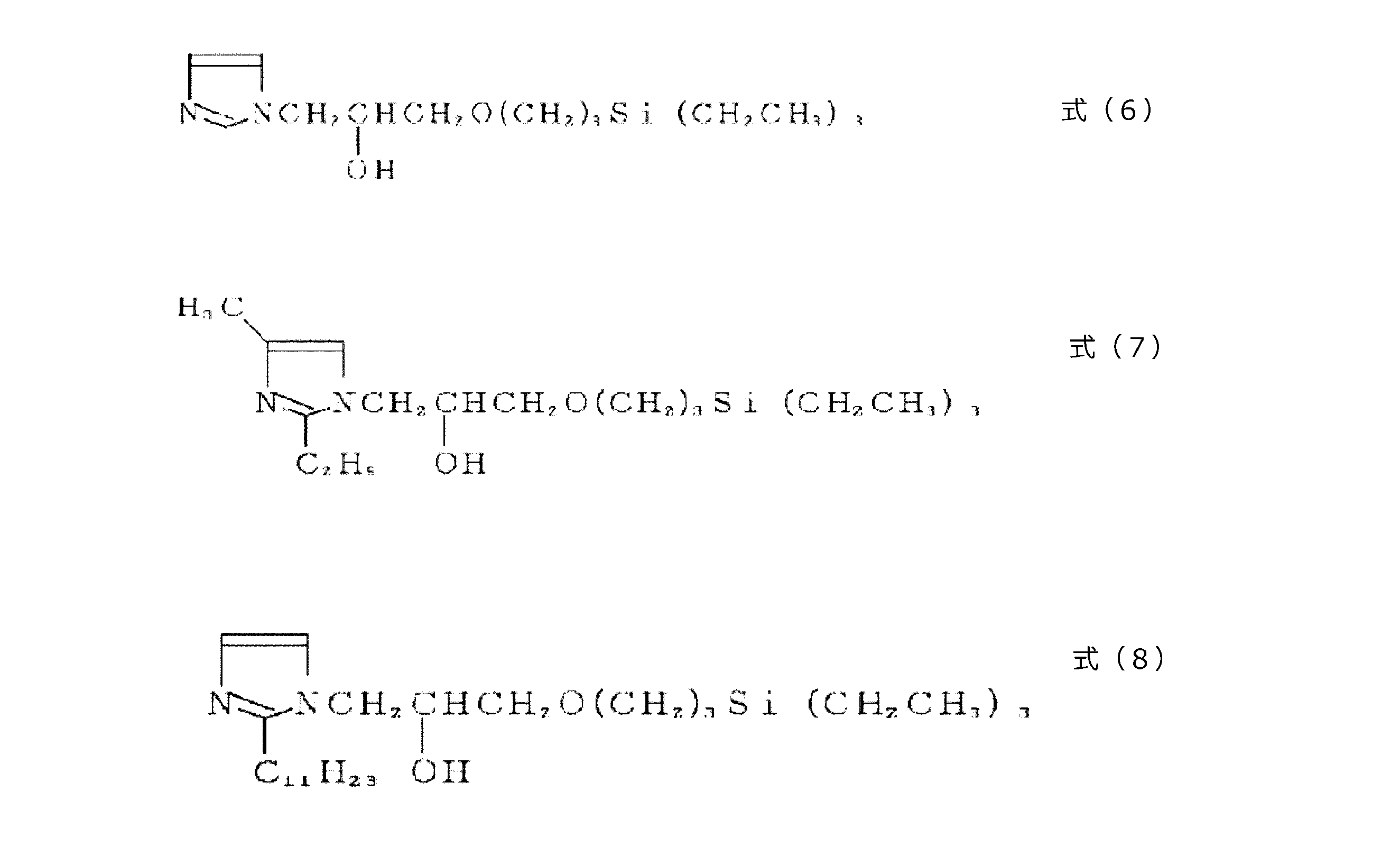
比較例28~30では、特許文献6(特開平6-256358号公報)の実施例1、2、3にある手法で合成した3種類の反応生成物(以下FBIA1=式(6)、FBIA2=式(7)、FBIA3=式(8))を、当該特許文献6の[0026]段落の内容に基づいて6wt%の濃度になるようにそれぞれメタノールに溶解させた溶液(液温35℃)を調製し、これに製箔した電解銅箔を5秒間浸漬させ、ドライヤーによって乾燥させることにより表面処理を行った。その後、大気オーブン(ヤマト科学株式会社製DF-411(商品名))を用いて180℃の温度で1時間加熱を行った。

銅箔を作用電極(WE、測定部面積1cm2)、白金電極を対極(CE)、塩化カロメル電極(SCE)を基準電極(RE)として、塩化カリウム(KCl)0.1N水溶液を電解液とする3電極セルを構成し、窒素ガスで十分に脱気したあと、北斗電工製電気化学測定装置HZ-3000(商品名)を用いて、カソード定電流800μAを入力し、電位信号の応答を観測した。横軸を測定時間、縦軸を電位値としたときに、最初に電位が時間に対してほぼ一定となる領域(第一プラトー電位領域)を検知し(図1参照)、この領域の中での最大の電位値を測定した。
図4に示したように、各実施例、各比較例で作製した銅箔を縦10cm×横5cmの長方形に切り、銅箔のマット面(M面)側を表にして、左端が幅2cmはみ出すように、コクヨ製TZ-1343(商品名)のステンレス直定規(C型 JIS1級 30cm)を重石として乗せた。その後、銅箔の縦方向の中央部分(図4中の線1の位置)と、その上下2cmの部分(図4中の線2と線3の位置)の計3点について、銅箔を置いた面からの端部の立ち上がりの高さ[mm]を測定し、3点の平均値を算出することにより、カール値を測定した。
得られたカールの度合いについて、次の基準で評価した。すなわち、カール値が0.5mm未満のものを優として「A」、0.5mm以上1.5mm未満となるものを良として「B」、1.5mm以上3.0mm未満となるものを可として「C」、3.0mm以上となるものを不可として「D」と、それぞれ表中に示した。
各実施例、各比較例で作製した銅箔(表面処理、およびドライヤーによる乾燥は行うが、大気オーブンによる乾燥は行わないもの)の両面に下記炭素材料からなる活物質スラリーペーストを用い、銅箔と活物質の密着性を下記により評価した。その結果を表1、2に示す。炭素材料としては塊状人造黒鉛を用い、該塊状人造黒鉛をNMP(N-メチル-2-ピロリドン)に8%PVDF(ポリフッ化ビニリデン)粉を溶かした溶液と混合してペースト状とし、このペーストを銅箔表面に約50μmの厚さに塗布して、180℃で1時間乾燥後圧延によるプレスを行い、さらに真空乾燥した。
この活物質塗布面に両面テープを貼り付け、支持板にも両面テープを貼り付け、両面テープ同士を張り合わせた。そして、JIS C 6471に準じる方法で引き剥がし角度90度にて剥離強度を測定した。以下の表には、電解銅箔のS面と支持板の間の剥離強度、電解銅箔のM面と支持板の間の剥離強度を、それぞれ測定した結果を示した。支持板としては、引き剥がし試験に供しても折れないような硬さを有するポリスチレン板を用いた。
このように形成した活物質層の密着性について、活物質剥離試験の結果を以下の基準で評価した。剥離強度が4000gf/cm以上のものを優として「A」、3000gf/cm以上4000gf/cm未満となるものを良として「B」、2000gf/cm以上3000gf/cm未満となるものを可として「C」、2000gf/cm未満となるものを不可として「D」と、それぞれ表中に示した。
銅箔表面付近の原子含有量を、アルバック・ファイ株式会社製XPS測定装置5600MC(商品名)を使用し下記条件で測定した。
到達真空度1×10⁻¹⁰Torr(Arガス導入時1×10⁻⁸Torr)、
X線:X線種単色化Al-Kα線、
出力300W、
検出面積800μmφ、
イオン線:イオン種Ar+、
加速電圧3kV、
掃引面積3×3mm2、
試料入射角45°(試料と検出器とのなす角)、
スパッタリングレート2.3nm/分(SiO2換算)
測定開始後5.2秒後(深さ0.2nm)における原子C、N、O、Cuの含有量の和を分母、原子Nの含有量を分子として、原子Nの量の原子百分率[atm%]を算出した。
なお、表中の窒素含有防錆化合物の名称は、BTAが1,2,3-ベンゾトリアゾール、TTAがトリルトリアゾール、EBTAはエチルベンゾトリアゾール、BIAはベンゾイミダゾールを示す。


このうち、実施例1~5は、窒素量が特に適切な範囲内(3~20atm%)であり、カール値は0.5mm未満の範囲となっており、活物質の剥離はほぼ問題のないレベルに抑制されている。実施例6~8は窒素量が20atm%を超えており、カール値は0.5mm未満に抑えられているものの、酸化皮膜と有機防錆層との密着性がやや劣るため、活物質の密着性はやや劣っているが、負極の品質に大きな問題はない。実施例9~11は窒素量が3atm%を下回っており、加熱乾燥に伴って生成する酸化皮膜量がやや多く、カール値は1.5~3.0mm未満とやや劣り、活物質の密着性もやや劣っているが、負極の品質に大きな問題はない。
一方、実施例12~22は、酸化皮膜の第一プラトー電位領域の最大電位が-800~-820mVの範囲に入っている例である。全体的に実施例1~11と比べてカール防止特性や活物質密着性がやや劣るが、負極の品質に大きな問題はない。
このうち、実施例12~16は、窒素量が特に適切な範囲内(3~20atm%)であり、カール値は0.5~1.5mm未満の範囲となっており、活物質の剥離はほぼ問題のないレベルに抑制されている。
実施例17~19は窒素量が20atm%を超えており、カール値は0.5~1.5mm未満に抑えられているものの、酸化皮膜と有機防錆層との密着性がやや劣るために活物質の密着性はやや劣っているが、負極の品質に大きな問題はない。
実施例20~22は窒素量が3atm%を下回っており、加熱乾燥に伴って生成する酸化皮膜量がやや多く、カール値は1.5~3.0mm未満とやや劣り、活物質の密着性はやや劣っているが、負極の品質に大きな問題はない。
比較例1は、窒素含有防錆化合物および炭素数4以上のケトン類による防錆処理を行っておらず、カール値は7.0mmを超えてかなり大きく、活物質の剥離がかなり大きかった。
比較例2は、銅箔表面がクロメート皮膜と共に酸化し、十分な密着性を持つ酸化皮膜が形成することができなかったため、6.0mmを超える大きなカールが発生し、活物質の剥離を抑制することはできなかった。
また、比較例3~9は、窒素含有防錆化合物は使用しているものの、炭素数4以上のケトン類を使用しなかったため、カールを十分に抑制することができず、活物質の剥離が大きかった。特に比較例3~4では、第一プラトー電位領域の最大電位が-800mV(vs.SCE)を下回る面と上回る面とがそれぞれ存在し、酸化皮膜の密着性が面ごとに異なっていたため、かえってカールが発生しやすくなっていた。
比較例10は、炭素数3のアセトンを使用したため、カールを十分に抑制することができず、活物質の剥離が大きかった。
比較例11~13は、タフピッチ銅の圧延により形成した圧延銅箔に対して、窒素含有防錆化合物および炭素数4以上のケトン類による防錆処理を行った試験例である。圧延銅箔では、内部に多く含有する酸素が加熱によって放出されて酸化皮膜に含有され、十分な密着性を持つ酸化皮膜を形成することができなかった。このため、4.0mmを超えるカールが発生し、活物質の剥離を抑制することができなかった。
このほか、比較例14~16におけるCBTにより形成した有機防錆層を形成した例、比較例17~19におけるCBT、DMAC、IPAを組み合わせて形成した有機防錆層を設け、必要に応じてシラン層もしくはクロメート層からなる中間層を設けた例、比較例20~22におけるBTAとシランカップリング剤からなる混合層を設けた例、比較例23~30におけるシランもしくはフッ素シランを分子構造中に含むアゾール化合物もしくはイミダゾール化合物からなる防錆層を設けた例では、いずれの場合においても、酸化皮膜の第一プラトー電位領域の最大電位が-800mV(vs.SCE)を上回っており、形成された防錆皮膜及び中間層に酸化膜の密着性をコントロールする能力がなく、加熱後のカールを十分に抑制することができず、活物質の剥離は大きかった。
Claims (5)
- 180℃×1時間加熱後に室温で測定した表面酸化皮膜の第一プラトー電位領域における最大電位が、光沢面とマット面の両面ともに-800mV以下(vs.SCE)であることを特徴とするリチウムイオン二次電池用表面処理電解銅箔。
- 180℃×1時間加熱後に室温で測定した表面酸化皮膜の第一プラトー電位領域における最大電位が、光沢面とマット面の両面ともに-820mV以下(vs.SCE)であることを特徴とするリチウムイオン二次電池用表面処理電解銅箔。
- 常態において、表面から0.2nmの深さにおける値として、原子C、N、O、Cuの内、原子Nの割合が、光沢面とマット面の両面ともに3~20atm%であることを特徴とする請求項1または請求項2に記載のリチウムイオン二次電池用表面処理電解銅箔。
- 請求項1~3のいずれか1項に記載のリチウムイオン二次電池用表面処理電解銅箔を負極集電体として用いた、リチウムイオン二次電池用電極。
- 請求項4に記載のリチウムイオン二次電池用電極を負極として用いた、リチウムイオン二次電池。
Priority Applications (3)
| Application Number | Priority Date | Filing Date | Title |
|---|---|---|---|
| JP2016535077A JP6012913B1 (ja) | 2015-01-19 | 2016-01-18 | リチウムイオン二次電池用表面処理電解銅箔、これを用いたリチウムイオン二次電池用電極およびリチウムイオン二次電池 |
| CN201680003056.XA CN107078305B (zh) | 2015-01-19 | 2016-01-18 | 锂离子二次电池用表面处理电解铜箔、使用该铜箔的锂离子二次电池用电极以及锂离子二次电池 |
| KR1020177006701A KR101828880B1 (ko) | 2015-01-19 | 2016-01-18 | 리튬 이온 2차 전지용 표면 처리 전해 동박, 이것을 이용한 리튬 이온 2차 전지용 전극 및 리튬 이온 2차 전지 |
Applications Claiming Priority (2)
| Application Number | Priority Date | Filing Date | Title |
|---|---|---|---|
| JP2015007793 | 2015-01-19 | ||
| JP2015-007793 | 2015-01-19 |
Publications (1)
| Publication Number | Publication Date |
|---|---|
| WO2016117498A1 true WO2016117498A1 (ja) | 2016-07-28 |
Family
ID=56417043
Family Applications (1)
| Application Number | Title | Priority Date | Filing Date |
|---|---|---|---|
| PCT/JP2016/051265 WO2016117498A1 (ja) | 2015-01-19 | 2016-01-18 | リチウムイオン二次電池用表面処理電解銅箔、これを用いたリチウムイオン二次電池用電極およびリチウムイオン二次電池 |
Country Status (5)
| Country | Link |
|---|---|
| JP (1) | JP6012913B1 (ja) |
| KR (1) | KR101828880B1 (ja) |
| CN (1) | CN107078305B (ja) |
| TW (1) | TWI624108B (ja) |
| WO (1) | WO2016117498A1 (ja) |
Cited By (4)
| Publication number | Priority date | Publication date | Assignee | Title |
|---|---|---|---|---|
| WO2018198905A1 (ja) * | 2017-04-25 | 2018-11-01 | 古河電気工業株式会社 | 表面処理銅箔 |
| JP2019536211A (ja) * | 2016-11-11 | 2019-12-12 | イルジン マテリアルズ カンパニー リミテッドIljin Materials Co., Ltd. | 二次電池用電解銅箔及びその製造方法 |
| WO2022085046A1 (ja) * | 2020-10-19 | 2022-04-28 | TeraWatt Technology株式会社 | リチウム2次電池 |
| WO2023053295A1 (ja) * | 2021-09-29 | 2023-04-06 | TeraWatt Technology株式会社 | リチウム2次電池 |
Families Citing this family (1)
| Publication number | Priority date | Publication date | Assignee | Title |
|---|---|---|---|---|
| WO2019111914A1 (ja) * | 2017-12-05 | 2019-06-13 | 古河電気工業株式会社 | 表面処理銅箔、並びにこれを用いた銅張積層板及びプリント配線板 |
Citations (8)
| Publication number | Priority date | Publication date | Assignee | Title |
|---|---|---|---|---|
| JPH07309846A (ja) * | 1994-05-20 | 1995-11-28 | Japan Energy Corp | 新規ベンゾトリアゾールフッ素シラン誘導体及びその製造方法並びにそれを用いる表面処理剤 |
| JP2008251469A (ja) * | 2007-03-30 | 2008-10-16 | Nikko Kinzoku Kk | 濡れ性に優れた銅箔及びその製造方法 |
| JP2012212528A (ja) * | 2011-03-30 | 2012-11-01 | Jx Nippon Mining & Metals Corp | 銅箔及びそれを用いたリチウムイオン二次電池用負極集電体及び負極材、ならびにリチウムイオン二次電池 |
| WO2013157574A1 (ja) * | 2012-04-19 | 2013-10-24 | 日本パーカライジング株式会社 | 自己析出型銅用表面処理剤および樹脂皮膜付き銅含有基材の製造方法 |
| JP5417436B2 (ja) * | 2009-09-11 | 2014-02-12 | Jx日鉱日石金属株式会社 | リチウムイオン電池集電体用銅箔 |
| JP2014240522A (ja) * | 2013-05-17 | 2014-12-25 | 四国化成工業株式会社 | 銅の表面処理液、表面処理方法及びその利用 |
| WO2015002158A1 (ja) * | 2013-07-02 | 2015-01-08 | 四国化成工業株式会社 | アゾールシラン化合物、表面処理液、表面処理方法およびその利用 |
| WO2015115177A1 (ja) * | 2014-01-29 | 2015-08-06 | 日本ゼオン株式会社 | 集電体コート用接着剤塗工液 |
Family Cites Families (7)
| Publication number | Priority date | Publication date | Assignee | Title |
|---|---|---|---|---|
| JP5109399B2 (ja) * | 2006-09-06 | 2012-12-26 | 日立化成工業株式会社 | 銅の表面処理方法 |
| CN102640333A (zh) * | 2009-11-05 | 2012-08-15 | Jx日矿日石金属株式会社 | 锂离子电池集电体用铜箔 |
| TWI466367B (zh) * | 2010-12-27 | 2014-12-21 | Furukawa Electric Co Ltd | A lithium ion secondary battery, an electrode for the secondary battery, an electrode for an electrolytic copper foil |
| JP5466664B2 (ja) * | 2011-04-08 | 2014-04-09 | 三井金属鉱業株式会社 | 多孔質金属箔およびその製造方法 |
| JP5400826B2 (ja) * | 2011-04-08 | 2014-01-29 | 三井金属鉱業株式会社 | 複合金属箔およびその製造方法 |
| JP6149031B2 (ja) * | 2012-03-30 | 2017-06-14 | 株式会社Uacj | 非水電解質二次電池用電極の製造方法 |
| KR20150052178A (ko) | 2012-09-28 | 2015-05-13 | 도요타 지도샤(주) | 이차 전지용 부극, 이차 전지, 차량 및 전지 탑재 기기 |
-
2016
- 2016-01-18 KR KR1020177006701A patent/KR101828880B1/ko active IP Right Grant
- 2016-01-18 JP JP2016535077A patent/JP6012913B1/ja active Active
- 2016-01-18 CN CN201680003056.XA patent/CN107078305B/zh active Active
- 2016-01-18 WO PCT/JP2016/051265 patent/WO2016117498A1/ja active Application Filing
- 2016-01-19 TW TW105101535A patent/TWI624108B/zh active
Patent Citations (8)
| Publication number | Priority date | Publication date | Assignee | Title |
|---|---|---|---|---|
| JPH07309846A (ja) * | 1994-05-20 | 1995-11-28 | Japan Energy Corp | 新規ベンゾトリアゾールフッ素シラン誘導体及びその製造方法並びにそれを用いる表面処理剤 |
| JP2008251469A (ja) * | 2007-03-30 | 2008-10-16 | Nikko Kinzoku Kk | 濡れ性に優れた銅箔及びその製造方法 |
| JP5417436B2 (ja) * | 2009-09-11 | 2014-02-12 | Jx日鉱日石金属株式会社 | リチウムイオン電池集電体用銅箔 |
| JP2012212528A (ja) * | 2011-03-30 | 2012-11-01 | Jx Nippon Mining & Metals Corp | 銅箔及びそれを用いたリチウムイオン二次電池用負極集電体及び負極材、ならびにリチウムイオン二次電池 |
| WO2013157574A1 (ja) * | 2012-04-19 | 2013-10-24 | 日本パーカライジング株式会社 | 自己析出型銅用表面処理剤および樹脂皮膜付き銅含有基材の製造方法 |
| JP2014240522A (ja) * | 2013-05-17 | 2014-12-25 | 四国化成工業株式会社 | 銅の表面処理液、表面処理方法及びその利用 |
| WO2015002158A1 (ja) * | 2013-07-02 | 2015-01-08 | 四国化成工業株式会社 | アゾールシラン化合物、表面処理液、表面処理方法およびその利用 |
| WO2015115177A1 (ja) * | 2014-01-29 | 2015-08-06 | 日本ゼオン株式会社 | 集電体コート用接着剤塗工液 |
Cited By (5)
| Publication number | Priority date | Publication date | Assignee | Title |
|---|---|---|---|---|
| JP2019536211A (ja) * | 2016-11-11 | 2019-12-12 | イルジン マテリアルズ カンパニー リミテッドIljin Materials Co., Ltd. | 二次電池用電解銅箔及びその製造方法 |
| WO2018198905A1 (ja) * | 2017-04-25 | 2018-11-01 | 古河電気工業株式会社 | 表面処理銅箔 |
| JPWO2018198905A1 (ja) * | 2017-04-25 | 2019-06-27 | 古河電気工業株式会社 | 表面処理銅箔 |
| WO2022085046A1 (ja) * | 2020-10-19 | 2022-04-28 | TeraWatt Technology株式会社 | リチウム2次電池 |
| WO2023053295A1 (ja) * | 2021-09-29 | 2023-04-06 | TeraWatt Technology株式会社 | リチウム2次電池 |
Also Published As
| Publication number | Publication date |
|---|---|
| JPWO2016117498A1 (ja) | 2017-04-27 |
| JP6012913B1 (ja) | 2016-10-25 |
| KR20170106643A (ko) | 2017-09-21 |
| TW201703322A (zh) | 2017-01-16 |
| KR101828880B1 (ko) | 2018-02-13 |
| CN107078305A (zh) | 2017-08-18 |
| TWI624108B (zh) | 2018-05-11 |
| CN107078305B (zh) | 2020-06-12 |
Similar Documents
| Publication | Publication Date | Title |
|---|---|---|
| JP6012913B1 (ja) | リチウムイオン二次電池用表面処理電解銅箔、これを用いたリチウムイオン二次電池用電極およびリチウムイオン二次電池 | |
| JP5625141B1 (ja) | リチウムイオン二次電池負極集電体用銅箔 | |
| JP5516751B2 (ja) | アルミニウム箔の製造方法 | |
| TWI682075B (zh) | 具有優化峰粗糙度的電解銅箔、包含其的電極、包含其的二次電池、及其製造方法 | |
| CN108270016B (zh) | 电解铜箔、电极、二次电池及其制造方法 | |
| WO2011078356A1 (ja) | 非水溶媒二次電池に用いる負極集電体用銅箔、その製造方法及び非水溶媒二次電池負極電極の製造方法 | |
| WO2010128681A1 (ja) | 2次電池用負極、電極用銅箔、2次電池および2次電池用負極の製造方法 | |
| Rehnlund et al. | Electrodeposition of vanadium oxide/manganese oxide hybrid thin films on nanostructured aluminum substrates | |
| JP5512585B2 (ja) | 銅箔及びそれを用いたリチウムイオン二次電池用負極集電体及び負極材、ならびにリチウムイオン二次電池 | |
| JP5081481B2 (ja) | 濡れ性に優れた銅箔及びその製造方法 | |
| JP2013211229A (ja) | 銅箔及びそれを用いたリチウムイオン二次電池用負極集電体及び負極材、ならびにリチウムイオン二次電池 | |
| WO2018062046A1 (ja) | 電極用アルミニウム部材および電極用アルミニウム部材の製造方法 | |
| WO2020090195A1 (ja) | リチウムイオン電池集電体用圧延銅箔及びリチウムイオン電池 | |
| JPH11158652A (ja) | 二次電池用電極材料の製造方法 | |
| JP6611751B2 (ja) | リチウムイオン電池集電体用圧延銅箔及びリチウムイオン電池 | |
| JP5356308B2 (ja) | 2次電池用負極、電極用銅箔、2次電池および2次電池用負極の製造方法 | |
| JP2005197096A (ja) | 非水電解液二次電池用負極及びその製造方法 | |
| JP2013165030A (ja) | 非水電解質二次電池ケース用鋼材 | |
| JP2017016929A (ja) | 固体高分子形燃料電池のセパレータ用チタン材 | |
| CN104204299A (zh) | 表面处理铜箔及其制造方法、锂离子二次电池用电极以及锂离子二次电池 |
Legal Events
| Date | Code | Title | Description |
|---|---|---|---|
| ENP | Entry into the national phase |
Ref document number: 2016535077 Country of ref document: JP Kind code of ref document: A |
|
| 121 | Ep: the epo has been informed by wipo that ep was designated in this application |
Ref document number: 16740105 Country of ref document: EP Kind code of ref document: A1 |
|
| ENP | Entry into the national phase |
Ref document number: 20177006701 Country of ref document: KR Kind code of ref document: A |
|
| NENP | Non-entry into the national phase |
Ref country code: DE |
|
| 122 | Ep: pct application non-entry in european phase |
Ref document number: 16740105 Country of ref document: EP Kind code of ref document: A1 |