WO2016093379A1 - 비자성 합금을 포함하는 열간가압변형 자석 및 이의 제조방법 - Google Patents
비자성 합금을 포함하는 열간가압변형 자석 및 이의 제조방법 Download PDFInfo
- Publication number
- WO2016093379A1 WO2016093379A1 PCT/KR2014/012006 KR2014012006W WO2016093379A1 WO 2016093379 A1 WO2016093379 A1 WO 2016093379A1 KR 2014012006 W KR2014012006 W KR 2014012006W WO 2016093379 A1 WO2016093379 A1 WO 2016093379A1
- Authority
- WO
- WIPO (PCT)
- Prior art keywords
- magnet
- alloy
- hot
- magnetic powder
- nonmagnetic
- Prior art date
Links
Images


Classifications
-
- B—PERFORMING OPERATIONS; TRANSPORTING
- B22—CASTING; POWDER METALLURGY
- B22F—WORKING METALLIC POWDER; MANUFACTURE OF ARTICLES FROM METALLIC POWDER; MAKING METALLIC POWDER; APPARATUS OR DEVICES SPECIALLY ADAPTED FOR METALLIC POWDER
- B22F3/00—Manufacture of workpieces or articles from metallic powder characterised by the manner of compacting or sintering; Apparatus specially adapted therefor ; Presses and furnaces
- B22F3/12—Both compacting and sintering
- B22F3/14—Both compacting and sintering simultaneously
-
- H—ELECTRICITY
- H01—ELECTRIC ELEMENTS
- H01F—MAGNETS; INDUCTANCES; TRANSFORMERS; SELECTION OF MATERIALS FOR THEIR MAGNETIC PROPERTIES
- H01F1/00—Magnets or magnetic bodies characterised by the magnetic materials therefor; Selection of materials for their magnetic properties
- H01F1/01—Magnets or magnetic bodies characterised by the magnetic materials therefor; Selection of materials for their magnetic properties of inorganic materials
- H01F1/03—Magnets or magnetic bodies characterised by the magnetic materials therefor; Selection of materials for their magnetic properties of inorganic materials characterised by their coercivity
- H01F1/032—Magnets or magnetic bodies characterised by the magnetic materials therefor; Selection of materials for their magnetic properties of inorganic materials characterised by their coercivity of hard-magnetic materials
- H01F1/04—Magnets or magnetic bodies characterised by the magnetic materials therefor; Selection of materials for their magnetic properties of inorganic materials characterised by their coercivity of hard-magnetic materials metals or alloys
- H01F1/047—Alloys characterised by their composition
- H01F1/053—Alloys characterised by their composition containing rare earth metals
- H01F1/055—Alloys characterised by their composition containing rare earth metals and magnetic transition metals, e.g. SmCo5
- H01F1/057—Alloys characterised by their composition containing rare earth metals and magnetic transition metals, e.g. SmCo5 and IIIa elements, e.g. Nd2Fe14B
- H01F1/0571—Alloys characterised by their composition containing rare earth metals and magnetic transition metals, e.g. SmCo5 and IIIa elements, e.g. Nd2Fe14B in the form of particles, e.g. rapid quenched powders or ribbon flakes
- H01F1/0575—Alloys characterised by their composition containing rare earth metals and magnetic transition metals, e.g. SmCo5 and IIIa elements, e.g. Nd2Fe14B in the form of particles, e.g. rapid quenched powders or ribbon flakes pressed, sintered or bonded together
- H01F1/0577—Alloys characterised by their composition containing rare earth metals and magnetic transition metals, e.g. SmCo5 and IIIa elements, e.g. Nd2Fe14B in the form of particles, e.g. rapid quenched powders or ribbon flakes pressed, sintered or bonded together sintered
-
- C—CHEMISTRY; METALLURGY
- C22—METALLURGY; FERROUS OR NON-FERROUS ALLOYS; TREATMENT OF ALLOYS OR NON-FERROUS METALS
- C22C—ALLOYS
- C22C1/00—Making non-ferrous alloys
- C22C1/04—Making non-ferrous alloys by powder metallurgy
- C22C1/0475—Impregnated alloys
-
- C—CHEMISTRY; METALLURGY
- C22—METALLURGY; FERROUS OR NON-FERROUS ALLOYS; TREATMENT OF ALLOYS OR NON-FERROUS METALS
- C22C—ALLOYS
- C22C12/00—Alloys based on antimony or bismuth
-
- C—CHEMISTRY; METALLURGY
- C22—METALLURGY; FERROUS OR NON-FERROUS ALLOYS; TREATMENT OF ALLOYS OR NON-FERROUS METALS
- C22C—ALLOYS
- C22C21/00—Alloys based on aluminium
-
- C—CHEMISTRY; METALLURGY
- C22—METALLURGY; FERROUS OR NON-FERROUS ALLOYS; TREATMENT OF ALLOYS OR NON-FERROUS METALS
- C22C—ALLOYS
- C22C23/00—Alloys based on magnesium
- C22C23/06—Alloys based on magnesium with a rare earth metal as the next major constituent
-
- C—CHEMISTRY; METALLURGY
- C22—METALLURGY; FERROUS OR NON-FERROUS ALLOYS; TREATMENT OF ALLOYS OR NON-FERROUS METALS
- C22C—ALLOYS
- C22C28/00—Alloys based on a metal not provided for in groups C22C5/00 - C22C27/00
-
- C—CHEMISTRY; METALLURGY
- C22—METALLURGY; FERROUS OR NON-FERROUS ALLOYS; TREATMENT OF ALLOYS OR NON-FERROUS METALS
- C22C—ALLOYS
- C22C33/00—Making ferrous alloys
- C22C33/02—Making ferrous alloys by powder metallurgy
- C22C33/0257—Making ferrous alloys by powder metallurgy characterised by the range of the alloying elements
- C22C33/0278—Making ferrous alloys by powder metallurgy characterised by the range of the alloying elements with at least one alloying element having a minimum content above 5%
-
- C—CHEMISTRY; METALLURGY
- C22—METALLURGY; FERROUS OR NON-FERROUS ALLOYS; TREATMENT OF ALLOYS OR NON-FERROUS METALS
- C22C—ALLOYS
- C22C38/00—Ferrous alloys, e.g. steel alloys
- C22C38/002—Ferrous alloys, e.g. steel alloys containing In, Mg, or other elements not provided for in one single group C22C38/001 - C22C38/60
-
- C—CHEMISTRY; METALLURGY
- C22—METALLURGY; FERROUS OR NON-FERROUS ALLOYS; TREATMENT OF ALLOYS OR NON-FERROUS METALS
- C22C—ALLOYS
- C22C38/00—Ferrous alloys, e.g. steel alloys
- C22C38/005—Ferrous alloys, e.g. steel alloys containing rare earths, i.e. Sc, Y, Lanthanides
-
- C—CHEMISTRY; METALLURGY
- C22—METALLURGY; FERROUS OR NON-FERROUS ALLOYS; TREATMENT OF ALLOYS OR NON-FERROUS METALS
- C22C—ALLOYS
- C22C38/00—Ferrous alloys, e.g. steel alloys
- C22C38/10—Ferrous alloys, e.g. steel alloys containing cobalt
-
- C—CHEMISTRY; METALLURGY
- C22—METALLURGY; FERROUS OR NON-FERROUS ALLOYS; TREATMENT OF ALLOYS OR NON-FERROUS METALS
- C22C—ALLOYS
- C22C38/00—Ferrous alloys, e.g. steel alloys
- C22C38/16—Ferrous alloys, e.g. steel alloys containing copper
-
- H—ELECTRICITY
- H01—ELECTRIC ELEMENTS
- H01F—MAGNETS; INDUCTANCES; TRANSFORMERS; SELECTION OF MATERIALS FOR THEIR MAGNETIC PROPERTIES
- H01F1/00—Magnets or magnetic bodies characterised by the magnetic materials therefor; Selection of materials for their magnetic properties
- H01F1/01—Magnets or magnetic bodies characterised by the magnetic materials therefor; Selection of materials for their magnetic properties of inorganic materials
- H01F1/03—Magnets or magnetic bodies characterised by the magnetic materials therefor; Selection of materials for their magnetic properties of inorganic materials characterised by their coercivity
- H01F1/032—Magnets or magnetic bodies characterised by the magnetic materials therefor; Selection of materials for their magnetic properties of inorganic materials characterised by their coercivity of hard-magnetic materials
- H01F1/04—Magnets or magnetic bodies characterised by the magnetic materials therefor; Selection of materials for their magnetic properties of inorganic materials characterised by their coercivity of hard-magnetic materials metals or alloys
- H01F1/047—Alloys characterised by their composition
- H01F1/053—Alloys characterised by their composition containing rare earth metals
- H01F1/055—Alloys characterised by their composition containing rare earth metals and magnetic transition metals, e.g. SmCo5
- H01F1/057—Alloys characterised by their composition containing rare earth metals and magnetic transition metals, e.g. SmCo5 and IIIa elements, e.g. Nd2Fe14B
- H01F1/0571—Alloys characterised by their composition containing rare earth metals and magnetic transition metals, e.g. SmCo5 and IIIa elements, e.g. Nd2Fe14B in the form of particles, e.g. rapid quenched powders or ribbon flakes
- H01F1/0575—Alloys characterised by their composition containing rare earth metals and magnetic transition metals, e.g. SmCo5 and IIIa elements, e.g. Nd2Fe14B in the form of particles, e.g. rapid quenched powders or ribbon flakes pressed, sintered or bonded together
- H01F1/0576—Alloys characterised by their composition containing rare earth metals and magnetic transition metals, e.g. SmCo5 and IIIa elements, e.g. Nd2Fe14B in the form of particles, e.g. rapid quenched powders or ribbon flakes pressed, sintered or bonded together pressed, e.g. hot working
-
- H—ELECTRICITY
- H01—ELECTRIC ELEMENTS
- H01F—MAGNETS; INDUCTANCES; TRANSFORMERS; SELECTION OF MATERIALS FOR THEIR MAGNETIC PROPERTIES
- H01F41/00—Apparatus or processes specially adapted for manufacturing or assembling magnets, inductances or transformers; Apparatus or processes specially adapted for manufacturing materials characterised by their magnetic properties
- H01F41/02—Apparatus or processes specially adapted for manufacturing or assembling magnets, inductances or transformers; Apparatus or processes specially adapted for manufacturing materials characterised by their magnetic properties for manufacturing cores, coils, or magnets
- H01F41/0253—Apparatus or processes specially adapted for manufacturing or assembling magnets, inductances or transformers; Apparatus or processes specially adapted for manufacturing materials characterised by their magnetic properties for manufacturing cores, coils, or magnets for manufacturing permanent magnets
- H01F41/0293—Apparatus or processes specially adapted for manufacturing or assembling magnets, inductances or transformers; Apparatus or processes specially adapted for manufacturing materials characterised by their magnetic properties for manufacturing cores, coils, or magnets for manufacturing permanent magnets diffusion of rare earth elements, e.g. Tb, Dy or Ho, into permanent magnets
-
- B—PERFORMING OPERATIONS; TRANSPORTING
- B22—CASTING; POWDER METALLURGY
- B22F—WORKING METALLIC POWDER; MANUFACTURE OF ARTICLES FROM METALLIC POWDER; MAKING METALLIC POWDER; APPARATUS OR DEVICES SPECIALLY ADAPTED FOR METALLIC POWDER
- B22F2998/00—Supplementary information concerning processes or compositions relating to powder metallurgy
- B22F2998/10—Processes characterised by the sequence of their steps
-
- C—CHEMISTRY; METALLURGY
- C22—METALLURGY; FERROUS OR NON-FERROUS ALLOYS; TREATMENT OF ALLOYS OR NON-FERROUS METALS
- C22C—ALLOYS
- C22C2200/00—Crystalline structure
- C22C2200/04—Nanocrystalline
-
- C—CHEMISTRY; METALLURGY
- C22—METALLURGY; FERROUS OR NON-FERROUS ALLOYS; TREATMENT OF ALLOYS OR NON-FERROUS METALS
- C22C—ALLOYS
- C22C2202/00—Physical properties
- C22C2202/02—Magnetic
Definitions
- the present invention relates to a hot-pressurized magnet including a nonmagnetic alloy distributed at a grain boundary, and unlike the permanent magnets by the conventional process, by effectively achieving magnetic shielding, the coercive force of the permanent magnets is improved, and a magnetic field is required. And a method of improving the residual magnetic flux density without.
- the most important device for this energy consumption is the motor, and its core material is the rare earth permanent magnet.
- High rare magnetic flux density (Br) and stable coercive force (iHc) are required for the rare earth permanent magnet to be used as an excellent material in various applications.
- One method of securing high coercive force of magnetic powder is to add heavy rare earth such as Dy to increase coercive force at room temperature.
- heavy rare earth metals such as Dy and soaring prices, the use of materials in the future will be limited.
- Dy when Dy is added, coercive force is improved, but residual magnetization is lowered, resulting in a weak strength of the magnet.
- a method for producing an anisotropic neodymium-based permanent magnet usually prepared by melting the metal, rapid cooling, milling the magnetic powder, and molding while applying a magnetic field, followed by sintering at a high temperature (1000 °C or more) and post-heat treatment It is manufactured through.
- one of the methods for securing the high coercive force of the magnetic powder is a method of miniaturizing the grain size to the terminal sphere size.
- the fine grains are finely pulverized by physical methods.
- the grain size of the magnetic powder itself needs to be fine before sintering during the steps of the manufacturing method.
- this method is rich in the nonmagnetic phase only on the surface of the magnet and is hardly diffused, so it is insufficient in the inside thereof, so that the grains cannot be uniformly isolated. Therefore, in this case, it is difficult to apply to a large magnet, there is a fear that the magnet is not uniform because the magnetic properties of the inside and outside is different.
- a non-magnetic alloy is uniformly distributed on the interface of grains to improve coercive force by the effect of magnetic shielding, and the magnetization direction is aligned in one direction due to the hot pressing deformation process, thereby increasing the residual magnetic flux density and the hot pressing strain magnet
- the purpose of the present invention is to provide a method for manufacturing a hot-pressurized magnet in which a nonmagnetic alloy is uniformly distributed at the interface of crystal grains by mixing the nonmagnetic alloy during the manufacturing process of the magnet.
- R-TM-B hot-pressure deformation magnet
- R-TM-B R is Nd, Dy, Pr, Tb, Ho, Sm, Sc, Y, La, Ce, Pm
- Preparing a magnetic powder from an alloy any one rare earth metal selected from the group consisting of Eu, Gd, Er, Tm, Yb, Lu, and combinations thereof;
- pressing and sintering the magnetic powder to produce a sintered body and
- hot deformation of the sintered body by applying heat and pressure, and during the production of the R-TM-B alloy of step (a), or before press sintering of step (b). It is characterized by including the addition of a nonmagnetic alloy.
- the magnetic powder of step (a) may be prepared by grinding an alloy ingot having an R-TM-B-based composition, and the R-TM-B-based alloy ingot may be, for example, an HDDR process, a melt spinning process, or a rapid solidification process. Or the like. Specifically, the alloy ingot may be melted, and the ingot having a ribbon shape may be manufactured by a method of rapidly cooling the molten alloy through high speed rolling.
- the ribbon-shaped ingot may be pulverized by an apparatus for performing milling, and the like.
- the pulverized powder may be a magnetic powder of step (a).
- the HDDR process is a process in which magnetic powder is prepared through a hydrogenation, disproportionation, dehydrogenation, and recombination process.
- the magnetic powder may be a polycrystalline particle containing a plurality of crystal grains therein, the average particle size of the magnetic powder may be 100 to 500 ⁇ m, the polycrystalline particles are generally containing a plurality of magnetic domains It may be a multi domain particle.
- the powder particle size should be pulverized to about 3 ⁇ m so that the particle size of the magnetic powder becomes a single crystal to facilitate magnetic field alignment. Therefore, rolling of strip caster cooling wheel should be carried out at low speed in the production of magnetic powder, and milling should also go through both coarse and fine grinding processes.
- the magnetic powder of the present invention is a polycrystalline or amorphous particle in which a large number of crystal grains are present in the particle and has an average powder size of 100 to 500 ⁇ m, cost and energy for the grinding process can be reduced. have.
- the step (b) may be a step of pressure sintering the magnetic powder prepared in the step (a).
- the step of pressing and sintering may be applied as long as sintering can be performed, and the method is not particularly limited.
- hot press sintering hot hydrostatic sintering, discharge plasma sintering, furnace sintering, microwave sintering, Or a combination thereof.
- the pressurizing and sintering may be performed at a temperature of 300 to 800 ° C. and a pressure of 30 to 1000 MPa.
- the pressure sintering is performed at the temperature, the nonmagnetic alloy may be primarily distributed in the grain boundary in the magnetic powder, and each magnetic powder may be concentrated to obtain a sintered compact having a dense structure. Even in this case, however, the powder particles in the sintered body may still be spherical or other irregular shapes, and only the powder particles may be compactly compressed, so that the magnetization directions of the domains in each powder coincide. As a result, the magnetic properties may not be expressed as a whole. In this case, the size of the crystal grains in the magnetic powder particles may be about 30 to 100 nm.
- the step (c) may be a step of hot pressing the sintered body formed in the step (b) at a constant temperature and a constant pressure condition.
- the step (c) is a step that can be performed at a higher temperature and pressure in the pressure sintering, and may be a step of compressing a densely shaped magnet, so that the particles in a state of being dense inside the sintered body are in the same direction as the pressure direction.
- the easy-to-magnetize axis rotates, most of them grow in the vertical direction of the pressure direction, and the width thereof increases, which can be performed in an apparatus in which all sides are open or blocked.
- the thickness of the sintered body can be reduced and the width can be carried out in a device that is open in all directions perpendicular to the direction in which the pressure is applied.
- a compacted sintered compact of magnetic powders is formed, and is strongly compressed due to high pressure in the hot-pressing deformation process, so that the magnetic powder particles and crystal grains having a size of about 30 to 100 nm present therein are in the form of a plate.
- the crystal grains deformed in this shape may have anisotropy in which the magnetization directions are aligned in one direction due to their crystallographic characteristics, and thus magnetic properties may be expressed.
- the hot pressing may be performed at a temperature of 500 to 1000 ° C. and a pressure of 50 to 1000 MPa.
- the strain of the hot compressive strain can be carried out at about 50 to 80%, which can be achieved in the above temperature and pressure ranges. That is, if the temperature is less than 500 °C, or if the pressure is less than 50 MPa and the strain is less than 30%, the particles and crystal grains may not be deformed into a plate shape that the magnetization direction can be aligned due to the crystallographic characteristics, the temperature is 1000 °C Exceeding the above causes rapid grain growth.
- the method may not include a magnetic field forming step of applying an external magnetic field.
- a magnetic field forming step of applying an external magnetic field When the crystal grains are deformed into a plate through continuous compression as described in the present invention, even if the magnetic field is not applied to the magnet by applying an external magnetic field, the crystal grains are crystallographically aligned in one direction. It is possible to have excellent residual magnetic flux density. Accordingly, there is no need for a magnetic field imparting device or a magnetic field forming step, thereby reducing the process cost and the device cost.
- a non-magnetic alloy having a melting point of more than 0 ° C. and 850 ° C. or less is produced during the production of the R-TM-B alloy of step (a) or before the pressure sintering of step (b). Can be added.
- the nonmagnetic alloy may be included at the interface of the grains, and there is no particular limitation on the timing of addition, but may be sufficient if it is added before hot pressure deformation is performed, and may be desirable if it is added before pressure sintering is performed. have.
- the nonmagnetic alloy can be applied without limitation as long as it has a low solubility in the main phase R-TM-B-based magnetic powder and does not penetrate into the grains and is easily distributed evenly at the boundary of the grains.
- the nonmagnetic alloy may be a low melting point alloy having a melting point of more than 0 ° C. and 850 ° C. or less, and preferably, a melting point of 400 to 700 ° C.
- the melting point of the non-magnetic alloy is in the temperature range, it may be most often lower than the temperature range during the pressure sintering process of step (b) or during the hot pressure deformation process of step (c), so that diffusion is It may be easy, and as a result, the nonmagnetic alloy coated on the surface of the magnetic powder particles may be uniformly distributed on the internal grain boundary through such diffusion.
- the nonmagnetic alloy may be represented by the following Chemical Formula 2:
- T is any one element selected from the group consisting of Nd, Dy, Pr, Tb, Ho, Sm, Sc, Y, La, Ce, Pm, Eu, Gd, Er, Tm, Yb and Lu
- M Is any one metal element selected from the group consisting of Cu, Al, Sb, Bi, Ga, Zn, Ni, Mg, Ba, B, Co, Fe, In, Pt, Ta and combinations thereof, where a is 0 ⁇ is a real number a ⁇ 1.
- the non-magnetic alloy Nd 0.84 Cu 0.16 , Nd 0.7 Cu 0.3 , Nd 0.85 Al 0.15 , Nd 0.08 Al 0.92 , Nd 0.03 Sb 0.97 , Nd 0.8 Ga 0.2 , Nd 0.769 Zn 0.231 , Nd 0.07 Mg 0.93 , Pr 0.84 Cu 0.16 , Pr 0.7 Cu 0.3 , Pr 0.85 Al 0.15 , Pr 0.08 Al 0.92 , Pr 0.03 Sb 0.97 , Pr 0.8 Ga 0.2 , Pr 0.769 Zn 0.231 , Pr 0.07 Mg 0.93 , Bi, Ga, Ni, Co and combinations thereof It may include any one selected from the group consisting of, for example, Nd 0.7 Cu 0.3 having a melting point of 520 °C, Nd 0.85 Al 0.15 at 635 °C, Nd 0.08 Al 0.92 at 640 °C, Nd 0.03 Sb 0.97 , Nd 0.8 Ga 0.2 at 651 ° C.,
- Nd-TM-B crystals are diffused through Nd-rich phases that are liquid by high temperature and high pressure of the pressure sintering process and the hot pressing strain process. It grows through the a-axis of the Nd-TM-B crystal, and the addition of the above-mentioned nonmagnetic alloy present at the eutectic point with Nd on the Nd-rich, as described above, is about 100 to more than the conventional pressure sintering and hot pressing. It is possible to perform pressure sintering and hot pressure deformation processes at relatively low temperatures of 200 ° C.
- the addition of the nonmagnetic alloys present at the eutectic melting point with Nd on the Nd-rich phase can lower the melting point more than the conventional melting point of 655 ° C, the only Nd-rich phase, and as the melting point is lowered, It is possible that the process of decomposition, diffusion and growth of the Nd-TM-B crystal phase can be carried out at lower temperatures, thereby eliminating the surface defects of the Nd-TM-B crystals in which the low melting point metal compound is the main phase at such low temperatures. At the same time, less coarsening of grains occurs, ultimately improving coercivity.
- the powder and magnetic powder of the nonmagnetic alloy may be mixed by any method such as dry or wet, and the nonmagnetic alloy is evenly applied to the surface of the magnetic powder. If it can be applied, the mixing method can be selected without particular limitation.
- the solvent does not contain water or carbon, it can be selected to minimize the oxidation of the magnetic powder and deterioration of the magnetic properties, any solvent that satisfies such conditions can be applied without particular limitation.
- the nonmagnetic alloy can be distributed on the surface of each magnetic powder by mixing the nonmagnetic alloy with the magnetic powder, the nonmagnetic alloy primarily distributed on the surface of each magnetic powder during pressure sintering is Penetration and diffusion into the magnetic powder may be distributed on the grain boundary. That is, since the nonmagnetic alloy starts to diffuse from the surface of the magnetic powder, the magnetic shielding can be uniformly completed both inside and outside of the magnet, thereby improving the coercive force.
- the nonmagnetic alloy may be included in an amount of 0.01 to 10 wt% based on the weight of the magnetic powder. If the amount of the nonmagnetic alloy is less than 0.01% by weight and is too small, the amount may be small enough to be sufficiently distributed at the interface of the grains contained in the magnetic powder, so that the magnetic shielding of the grains may not be performed normally. When included in excess of 10% by weight, only the nonmagnetic alloy is agglomerated due to the excessive addition, so that an unnecessary nonmagnetic phase is present in the magnet, which may adversely affect the magnetic properties.
- step (b) When the nonmagnetic alloy is added in step (b) in the method of manufacturing a hot-pressurized strain magnet of the present invention, between the steps (b) and (c), further comprising the step of performing an additional heat treatment on the sintered body.
- the heat treatment in this step may be carried out at a temperature of 400 to 800 °C, heat treatment may be performed for less than 24 hours.
- the temperature and the treatment time of the heat treatment can be adjusted according to the melting point of the non-magnetic alloy is added, if it exceeds 800 °C, the growth between the grains occurs due to the presence of the non-magnetic alloy distributed in the interface of the crystal grains, Since it may be coarsened, it is preferably carried out in the above temperature range.
- This additional heat treatment may be a step that allows the nonmagnetic alloy to be evenly distributed on both the grain boundaries inside and outside the magnet, and by uniformly inducing the effect of more complete magnetic shielding, and through such heat treatment, The coercive force of the finally manufactured magnet can be further improved.
- the diffusion of penetration into the grain boundary of the nonmagnetic alloy may occur primarily during press sintering, and the nonmagnetic alloy distributed on the surface of the magnetic powder during the hot pressing deformation is secondary to the grain boundary inside thereof. Permeate diffusion can occur, so that the nonmagnetic alloy can be more evenly distributed on the grain boundaries.
- the size of the particles inside the magnet is reduced to the size of the terminal sphere to prevent coarsening of the crystal grains due to the growth between the grains in the manufacturing process, or to not only the powder grain boundary but also the powder particles
- the nonmagnetic alloy by mixing the nonmagnetic alloy and magnetic powder in advance and inducing diffusion into the powder particles several times, the nonmagnetic alloy is distributed not only at the interface of the powder particles, but also at the grain boundaries inside the sintered body. Since isolation is made between particles or grains by the nonmagnetic alloy, the coercive force can be considerably improved.
- the magnetization direction alignment degree of each grain or domain it is possible to align the magnetization magnetization direction in one direction, so that the residual magnetic flux density can be excellent.
- the coercive force may be improved through coarsening of crystal grains or easy diffusion of the nonmagnetic alloy, or by mixing the nonmagnetic alloy with magnetic powder
- coercive force can be improved by achieving a firm magnetic shielding .
- the hot-pressurized magnet includes: anisotropic plate-shaped crystal grains; And a nonmagnetic alloy distributed at the interface of the crystal grains.
- the R-TM-B-based hot pressing strain magnet may be represented by the following formula (1).
- R 'and R are selected from the group consisting of Nd, Dy, Pr, Tb, Ho, Sm, Sc, Y, La, Ce, Pm, Eu, Gd, Er, Tm, Yb, Lu, and combinations thereof Which is a rare earth metal, where x is a real number of 0 ⁇ x ⁇ 1.0).
- Anisotropic platelet grains present in the particles may have a long axis of 100 to 1000 nm.
- the contents of the entire contents of the nonmagnetic alloy, the contents of the anisotropic crystal grains, and the contents of the plate-shaped particles including the same are overlapped with those described in the method of manufacturing the hot-pressurized magnet, and thus the description thereof is omitted.
- a hot-pressurized magnet of the present invention by adding a non-magnetic alloy before performing sintering and introducing a hot-pressurizing step, it is possible to distribute the non-magnetic alloy to the boundary of the grains in the magnetic powder particles. As a result, isolation between particles or grains is made by the nonmagnetic alloy, and thus, a hot-pressurized magnet with improved coercivity and residual magnetic flux density can be manufactured in a more economical process.
- Figure 1 shows a grain boundary TEM observation picture of the permanent magnet prepared in (a) Comparative Example 1, (b) Example 2 and (c) Example 3.
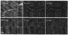
- Figure 2 shows a photograph of the EDS-mapping analysis of the permanent magnet prepared in (a) Example 2 and (b) Example 3.
- Figure 3 shows the SEM observation photograph of Example 4-3 before (a) heat treatment and (b) heat treatment.
- Nd-Fe-B-based powder (Nd 30 B 0.9 Co 4.1 Ga 0.5 Fe Bal. ) As a raw material was melted, and the molten liquid was injected into a cooling roll rotating at high speed to prepare a ribbon alloy (melt spinning step). .
- the ribbon-shaped ingot produced by the rolling process was milled with a stamp mill and ground to a size of about 200 ⁇ m, thereby preparing a magnetic powder.
- Nd 0.84 Cu 0.16 was 0.5 wt% (Example 2-1), 1.0 wt% (Example 2-2) and 1.5 wt% (Example 2-3) based on the weight of the magnetic powder, respectively.
- these powders were dry mixed with the respective magnetic powders (prepared in Example 1 above).
- the mixed powders are injected into an extrusion mold for molding (press sintering), and pressurized at a pressure of about 150 MPa and a temperature of about 700 ° C. to use a hot press to obtain a relative density of 99%.
- press sintering By pressure sintering.
- the sintered compact extruded from the mold was pressurized at about 750 ° C. using an open press device, and hot press deformation was performed at a strain of about 70% so that the crystal grains in the magnetic powder became platelets. It was. Due to the pressurization, the magnetization directions of the crystal grains contained in each powder particle were aligned in one direction, whereby anisotropic hot-pressurized magnets each containing 0.5, 1.0, and 1.5% by weight of the nonmagnetic alloy (Examples 2-1 to 1, respectively) 2-3) was prepared.
- Anisotropic hot-pressurized magnets were manufactured in the same manner as in Example 2, except that Pr 0.84 Cu 0.16 was used instead of Nd 0.84 Cu 0.16 (% by weight) as the nonmagnetic alloy.
- Example 2 (Example 2-1, 2-2 and 2-3) except that the sintered body subjected to the pressure sintering was performed for an additional heat treatment for about 2 hours at a temperature of about 575 °C the Example 2 In the same manner as in the hot pressing strain magnets were prepared (Examples 4-1 to 4-3, respectively).
- a magnetic powder prepared in Example 1 was prepared in the same manner as in Example 2 except that a nonmagnetic alloy was not added.
Landscapes
- Chemical & Material Sciences (AREA)
- Engineering & Computer Science (AREA)
- Mechanical Engineering (AREA)
- Materials Engineering (AREA)
- Metallurgy (AREA)
- Organic Chemistry (AREA)
- Power Engineering (AREA)
- Manufacturing & Machinery (AREA)
- Crystallography & Structural Chemistry (AREA)
- Inorganic Chemistry (AREA)
- Hard Magnetic Materials (AREA)
- Manufacturing Cores, Coils, And Magnets (AREA)
- Powder Metallurgy (AREA)
Priority Applications (4)
| Application Number | Priority Date | Filing Date | Title |
|---|---|---|---|
| JP2017522941A JP2018505540A (ja) | 2014-12-08 | 2014-12-08 | 非磁性合金を含む熱間加圧変形磁石及びその製造方法 |
| CN201480083350.7A CN107077935A (zh) | 2014-12-08 | 2014-12-08 | 包含非磁性合金的热压变形的磁体及其制造方法 |
| US15/521,131 US10950373B2 (en) | 2014-12-08 | 2014-12-08 | Hot-pressed and deformed magnet comprising nonmagnetic alloy and method for manufacturing same |
| PCT/KR2014/012006 WO2016093379A1 (ko) | 2014-12-08 | 2014-12-08 | 비자성 합금을 포함하는 열간가압변형 자석 및 이의 제조방법 |
Applications Claiming Priority (1)
| Application Number | Priority Date | Filing Date | Title |
|---|---|---|---|
| PCT/KR2014/012006 WO2016093379A1 (ko) | 2014-12-08 | 2014-12-08 | 비자성 합금을 포함하는 열간가압변형 자석 및 이의 제조방법 |
Publications (1)
| Publication Number | Publication Date |
|---|---|
| WO2016093379A1 true WO2016093379A1 (ko) | 2016-06-16 |
Family
ID=56107552
Family Applications (1)
| Application Number | Title | Priority Date | Filing Date |
|---|---|---|---|
| PCT/KR2014/012006 WO2016093379A1 (ko) | 2014-12-08 | 2014-12-08 | 비자성 합금을 포함하는 열간가압변형 자석 및 이의 제조방법 |
Country Status (4)
| Country | Link |
|---|---|
| US (1) | US10950373B2 (zh) |
| JP (1) | JP2018505540A (zh) |
| CN (1) | CN107077935A (zh) |
| WO (1) | WO2016093379A1 (zh) |
Families Citing this family (10)
| Publication number | Priority date | Publication date | Assignee | Title |
|---|---|---|---|---|
| WO2008045327A2 (en) | 2006-10-06 | 2008-04-17 | Kovio, Inc. | Silicon polymers, methods of polymerizing silicon compounds, and methods of forming thin films from such silicon polymers |
| JP6610957B2 (ja) * | 2016-08-17 | 2019-11-27 | 日立金属株式会社 | R−t−b系焼結磁石の製造方法 |
| CN109338166A (zh) * | 2018-09-25 | 2019-02-15 | 全球能源互联网研究院有限公司 | 一种Al-Er-B耐热合金单丝及其制备方法 |
| CN110165847B (zh) * | 2019-06-11 | 2021-01-26 | 深圳市瑞达美磁业有限公司 | 不同宽度波形的径向各向异性多极实心磁体的生产方法 |
| CN111370219B (zh) * | 2020-04-22 | 2021-07-20 | 安徽吉华新材料有限公司 | 一种钕铁硼废旧磁钢全循环回收利用生产新永磁体的制备工艺 |
| CN112342475A (zh) * | 2020-10-13 | 2021-02-09 | 东南大学 | 一种微合金化重稀土基非晶合金及其制备方法和应用 |
| CN113871121A (zh) * | 2021-09-24 | 2021-12-31 | 烟台东星磁性材料股份有限公司 | 耐高温磁体及其制造方法 |
| CN113620701B (zh) * | 2021-09-29 | 2023-04-18 | 海安南京大学高新技术研究院 | 一种超细晶耐高温高频锰锌铁氧体制备方法 |
| CN114678180B (zh) * | 2022-03-21 | 2023-04-14 | 电子科技大学 | 具有低场旋转磁热效应的多晶HoB2合金及其制备方法 |
| CN116230346B (zh) * | 2023-02-16 | 2023-08-22 | 四川大学 | 一种各向异性纳米晶稀土永磁体及制备方法 |
Citations (5)
| Publication number | Priority date | Publication date | Assignee | Title |
|---|---|---|---|---|
| KR19980043534A (ko) * | 1996-12-03 | 1998-09-05 | 오상수 | 이방성 영구자석 제조방법 |
| JP2001323343A (ja) * | 2000-05-12 | 2001-11-22 | Isuzu Motors Ltd | 高性能希土類永久磁石用合金及びその製造方法 |
| KR101087574B1 (ko) * | 2009-02-26 | 2011-11-28 | 한양대학교 산학협력단 | 반복 열처리를 통한 소결자석의 제조방법 및 그로부터 제조된 소결자석 |
| JP2012049492A (ja) * | 2010-07-30 | 2012-03-08 | Hitachi Metals Ltd | 希土類永久磁石の製造方法 |
| JP2012234985A (ja) * | 2011-05-02 | 2012-11-29 | Toyota Motor Corp | 高保磁力NdFeB磁石の製法 |
Family Cites Families (22)
| Publication number | Priority date | Publication date | Assignee | Title |
|---|---|---|---|---|
| US4765848A (en) * | 1984-12-31 | 1988-08-23 | Kaneo Mohri | Permanent magnent and method for producing same |
| US5125988A (en) * | 1987-03-02 | 1992-06-30 | Seiko Epson Corporation | Rare earth-iron system permanent magnet and process for producing the same |
| IE891581A1 (en) * | 1988-06-20 | 1991-01-02 | Seiko Epson Corp | Permanent magnet and a manufacturing method thereof |
| US5100485A (en) * | 1988-06-21 | 1992-03-31 | Matsushita Electric Industrial Co., Ltd. | Method for manufacturing permanent magnets |
| JP3037699B2 (ja) * | 1988-09-30 | 2000-04-24 | 日立金属株式会社 | 耐割れ性及び配向性を改善した温間加工磁石ならびにその製造方法 |
| JPH09275004A (ja) | 1995-07-07 | 1997-10-21 | Daido Steel Co Ltd | 永久磁石とその製造方法 |
| JP3267133B2 (ja) | 1995-12-18 | 2002-03-18 | 昭和電工株式会社 | 希土類磁石用合金及びその製造方法並びに永久磁石の製造方法 |
| KR19980043534U (ko) * | 1996-12-24 | 1998-09-25 | 박병재 | 자동차의 카울 크로스바 장착구조 |
| KR100771676B1 (ko) * | 2000-10-04 | 2007-10-31 | 가부시키가이샤 네오맥스 | 희토류 소결자석 및 그 제조방법 |
| CN103295713B (zh) | 2006-01-31 | 2016-08-10 | 日立金属株式会社 | R-Fe-B类稀土烧结磁铁 |
| JP2010263172A (ja) | 2008-07-04 | 2010-11-18 | Daido Steel Co Ltd | 希土類磁石およびその製造方法 |
| US20130068992A1 (en) | 2010-05-20 | 2013-03-21 | Kazuhiro Hono | Method for producing rare earth permanent magnets, and rare earth permanent magnets |
| CA2811451C (en) * | 2010-09-15 | 2016-11-01 | Toyota Jidosha Kabushiki Kaisha | Production method of rare earth magnet |
| US20140132376A1 (en) * | 2011-05-18 | 2014-05-15 | The Regents Of The University Of California | Nanostructured high-strength permanent magnets |
| JP6089535B2 (ja) | 2011-10-28 | 2017-03-08 | Tdk株式会社 | R−t−b系焼結磁石 |
| JP5640954B2 (ja) * | 2011-11-14 | 2014-12-17 | トヨタ自動車株式会社 | 希土類磁石の製造方法 |
| JP2013149862A (ja) | 2012-01-20 | 2013-08-01 | Toyota Motor Corp | 希土類磁石の製造方法 |
| JP5742813B2 (ja) | 2012-01-26 | 2015-07-01 | トヨタ自動車株式会社 | 希土類磁石の製造方法 |
| JP5790617B2 (ja) * | 2012-10-18 | 2015-10-07 | トヨタ自動車株式会社 | 希土類磁石の製造方法 |
| JP5751237B2 (ja) | 2012-11-02 | 2015-07-22 | トヨタ自動車株式会社 | 希土類磁石とその製造方法 |
| WO2014148145A1 (ja) * | 2013-03-22 | 2014-09-25 | Tdk株式会社 | R-t-b系永久磁石 |
| JP5915637B2 (ja) * | 2013-12-19 | 2016-05-11 | トヨタ自動車株式会社 | 希土類磁石の製造方法 |
-
2014
- 2014-12-08 CN CN201480083350.7A patent/CN107077935A/zh active Pending
- 2014-12-08 WO PCT/KR2014/012006 patent/WO2016093379A1/ko active Application Filing
- 2014-12-08 JP JP2017522941A patent/JP2018505540A/ja active Pending
- 2014-12-08 US US15/521,131 patent/US10950373B2/en active Active
Patent Citations (5)
| Publication number | Priority date | Publication date | Assignee | Title |
|---|---|---|---|---|
| KR19980043534A (ko) * | 1996-12-03 | 1998-09-05 | 오상수 | 이방성 영구자석 제조방법 |
| JP2001323343A (ja) * | 2000-05-12 | 2001-11-22 | Isuzu Motors Ltd | 高性能希土類永久磁石用合金及びその製造方法 |
| KR101087574B1 (ko) * | 2009-02-26 | 2011-11-28 | 한양대학교 산학협력단 | 반복 열처리를 통한 소결자석의 제조방법 및 그로부터 제조된 소결자석 |
| JP2012049492A (ja) * | 2010-07-30 | 2012-03-08 | Hitachi Metals Ltd | 希土類永久磁石の製造方法 |
| JP2012234985A (ja) * | 2011-05-02 | 2012-11-29 | Toyota Motor Corp | 高保磁力NdFeB磁石の製法 |
Also Published As
| Publication number | Publication date |
|---|---|
| JP2018505540A (ja) | 2018-02-22 |
| CN107077935A (zh) | 2017-08-18 |
| US20170330658A1 (en) | 2017-11-16 |
| US10950373B2 (en) | 2021-03-16 |
Similar Documents
| Publication | Publication Date | Title |
|---|---|---|
| WO2016093379A1 (ko) | 비자성 합금을 포함하는 열간가압변형 자석 및 이의 제조방법 | |
| WO2016175377A1 (ko) | 열적 안정성이 향상된 망간비스무트계 소결자석 및 이들의 제조 방법 | |
| WO2015046732A1 (ko) | 열간가압성형 공정을 이용한 이방성 열간가압성형 자석의 제조방법 및 이 방법으로 제조된 열간가압성형 자석 | |
| KR101535487B1 (ko) | Mn-Bi계 자성체, 이의 제조방법, Mn-Bi계 소결자석 및 이의 제조방법 | |
| WO2016171321A1 (ko) | 망간비스무트를 포함한 이방성 복합 소결 자석 및 이의 상압소결 방법 | |
| KR102215818B1 (ko) | 비자성 합금을 포함하는 열간가압변형 자석 및 이의 제조방법 | |
| US20160027564A1 (en) | METHOD FOR PRODUCING RFeB SYSTEM SINTERED MAGNET AND RFeB SYSTEM SINTERED MAGNET PRODUCED BY THE SAME | |
| EP3041005A1 (en) | Anisotropic complex sintered magnet comprising mnbi which has improved magnetic properties and method of preparing the same | |
| CN111834118B (zh) | 一种提高烧结钕铁硼磁体矫顽力的方法及烧结钕铁硼磁体 | |
| CN101834045B (zh) | 含钇的钕铁硼永磁材料及制造方法 | |
| JPS61289605A (ja) | 希土類−鉄−ホウ素永久磁石の製造方法 | |
| EP0249973B1 (en) | Permanent magnetic material and method for producing the same | |
| CN112562952A (zh) | 一种钕铁硼永磁材料及其制备方法 | |
| WO2017181669A1 (zh) | 一种高取向度烧结钕铁硼永磁材料的制备方法 | |
| JPS62276803A (ja) | 希土類−鉄系永久磁石 | |
| WO2019212101A1 (ko) | 희토류 영구자석의 제조방법 | |
| US11987868B2 (en) | Preparation method of a rare earth anisotropic bonded magnetic powder | |
| WO2016010348A9 (ko) | 중희토류 원소를 포함하지 않는 r-fe-b계 소결자석 및 이의 제조방법 | |
| CN113517104B (zh) | 主辅相合金钐钴磁体材料、烧结体用材料、其制备方法和应用 | |
| WO2021071236A1 (ko) | 소결 자석의 제조 방법 | |
| CN113539664B (zh) | 一种Sm基各向异性复合磁体的制备方法 | |
| WO2014204106A1 (ko) | 영구 자석의 제조 방법 | |
| WO2022191349A1 (ko) | 열간변형 영구자석의 제조방법 | |
| CN114944278B (zh) | 一种高性能稀土钴基永磁材料及其制备方法和应用 | |
| WO2023063539A1 (ko) | Mn-bi 계 수지자석 제조 방법 및 이로부터 제조된 mn-bi 계 수지자석 |
Legal Events
| Date | Code | Title | Description |
|---|---|---|---|
| 121 | Ep: the epo has been informed by wipo that ep was designated in this application |
Ref document number: 14907756 Country of ref document: EP Kind code of ref document: A1 |
|
| WWE | Wipo information: entry into national phase |
Ref document number: 15521131 Country of ref document: US |
|
| ENP | Entry into the national phase |
Ref document number: 2017522941 Country of ref document: JP Kind code of ref document: A |
|
| NENP | Non-entry into the national phase |
Ref country code: DE |
|
| 122 | Ep: pct application non-entry in european phase |
Ref document number: 14907756 Country of ref document: EP Kind code of ref document: A1 |