WO2016080342A1 - 積層フィルム - Google Patents
積層フィルム Download PDFInfo
- Publication number
- WO2016080342A1 WO2016080342A1 PCT/JP2015/082107 JP2015082107W WO2016080342A1 WO 2016080342 A1 WO2016080342 A1 WO 2016080342A1 JP 2015082107 W JP2015082107 W JP 2015082107W WO 2016080342 A1 WO2016080342 A1 WO 2016080342A1
- Authority
- WO
- WIPO (PCT)
- Prior art keywords
- film
- laminated film
- laminated
- width direction
- stretching
- Prior art date
- Legal status (The legal status is an assumption and is not a legal conclusion. Google has not performed a legal analysis and makes no representation as to the accuracy of the status listed.)
- Ceased
Links
Classifications
-
- B—PERFORMING OPERATIONS; TRANSPORTING
- B29—WORKING OF PLASTICS; WORKING OF SUBSTANCES IN A PLASTIC STATE IN GENERAL
- B29C—SHAPING OR JOINING OF PLASTICS; SHAPING OF MATERIAL IN A PLASTIC STATE, NOT OTHERWISE PROVIDED FOR; AFTER-TREATMENT OF THE SHAPED PRODUCTS, e.g. REPAIRING
- B29C55/00—Shaping by stretching, e.g. drawing through a die; Apparatus therefor
- B29C55/02—Shaping by stretching, e.g. drawing through a die; Apparatus therefor of plates or sheets
-
- B—PERFORMING OPERATIONS; TRANSPORTING
- B32—LAYERED PRODUCTS
- B32B—LAYERED PRODUCTS, i.e. PRODUCTS BUILT-UP OF STRATA OF FLAT OR NON-FLAT, e.g. CELLULAR OR HONEYCOMB, FORM
- B32B27/00—Layered products comprising a layer of synthetic resin
- B32B27/06—Layered products comprising a layer of synthetic resin as the main or only constituent of a layer, which is next to another layer of the same or of a different material
- B32B27/08—Layered products comprising a layer of synthetic resin as the main or only constituent of a layer, which is next to another layer of the same or of a different material of synthetic resin
-
- B—PERFORMING OPERATIONS; TRANSPORTING
- B32—LAYERED PRODUCTS
- B32B—LAYERED PRODUCTS, i.e. PRODUCTS BUILT-UP OF STRATA OF FLAT OR NON-FLAT, e.g. CELLULAR OR HONEYCOMB, FORM
- B32B27/00—Layered products comprising a layer of synthetic resin
- B32B27/36—Layered products comprising a layer of synthetic resin comprising polyesters
-
- G—PHYSICS
- G02—OPTICS
- G02B—OPTICAL ELEMENTS, SYSTEMS OR APPARATUS
- G02B5/00—Optical elements other than lenses
- G02B5/30—Polarising elements
-
- B—PERFORMING OPERATIONS; TRANSPORTING
- B32—LAYERED PRODUCTS
- B32B—LAYERED PRODUCTS, i.e. PRODUCTS BUILT-UP OF STRATA OF FLAT OR NON-FLAT, e.g. CELLULAR OR HONEYCOMB, FORM
- B32B2250/00—Layers arrangement
- B32B2250/05—5 or more layers
-
- B—PERFORMING OPERATIONS; TRANSPORTING
- B32—LAYERED PRODUCTS
- B32B—LAYERED PRODUCTS, i.e. PRODUCTS BUILT-UP OF STRATA OF FLAT OR NON-FLAT, e.g. CELLULAR OR HONEYCOMB, FORM
- B32B2250/00—Layers arrangement
- B32B2250/24—All layers being polymeric
-
- B—PERFORMING OPERATIONS; TRANSPORTING
- B32—LAYERED PRODUCTS
- B32B—LAYERED PRODUCTS, i.e. PRODUCTS BUILT-UP OF STRATA OF FLAT OR NON-FLAT, e.g. CELLULAR OR HONEYCOMB, FORM
- B32B7/00—Layered products characterised by the relation between layers; Layered products characterised by the relative orientation of features between layers, or by the relative values of a measurable parameter between layers, i.e. products comprising layers having different physical, chemical or physicochemical properties; Layered products characterised by the interconnection of layers
- B32B7/02—Physical, chemical or physicochemical properties
- B32B7/023—Optical properties
Definitions
- the present invention relates to a laminated film that can be suitably used as a polarizing plate protective film. Moreover, it is related with the polarizing plate which uses the laminated
- Thermoplastic resin films especially biaxially stretched polyester films, have excellent properties such as mechanical properties, electrical properties, dimensional stability, transparency, and chemical resistance. Widely used as a substrate film in applications.
- various optical films such as a polarizing plate protective film and a transparent conductive film is increasing.
- polarizing plate protective film applications low moisture permeability, mechanical strength, and
- TAC triacetyl cellulose
- Patent Document 1 For example, although a retardation of 400 nm or less is proposed for a laminated film, there is a problem that it is not used for a polarizing plate of a liquid crystal display because of a large thickness retardation (Patent Document 1). Moreover, although the polyester film for polarizer protection is proposed, retardation was large and suppression of interference color and rainbow nonuniformity was not enough (patent document 2). A polyester film for protecting a polarizer having a UV cut performance and a retardation of 400 nm or less has been proposed. However, since a film forming condition for increasing visibility and bowing due to low transmittance is adopted, There was a big problem in the variation in the phase difference between the directions (Patent Document 3).
- the problem of the present invention is to solve the problems described above.
- it is a biaxially stretched polyester film that is low-cost and can be thinned, but has low retardation, and when it is mounted on a display device such as a large-screen liquid crystal display, it causes uneven color, rainbow unevenness, and interference color
- An object of the present invention is to provide a laminated film excellent in post-workability without exhibiting.
- the above-described problems are laminated films in which three or more layers are laminated in the thickness direction, the in-plane direction retardation (Re) is 0 to 400 nm, the thickness direction retardation (Rth) is 0 to 1500 nm, and the Re variation is wide. 18% or less in the direction, Young's modulus in the longitudinal direction and the width direction is 2 GPa or more, the elongation at break in the longitudinal direction and the width direction is 50% or more, the film thickness of the laminated film is 40 ⁇ m or less, and the width of the film is 400 mm or more Can be achieved by a laminated film.
- the laminated film of the present invention When the laminated film of the present invention is mounted on a display device for a large-screen liquid crystal display as a polarizing plate protective film, it has an effect that it has little color unevenness and good appearance and can be displayed with high quality. As a more preferred embodiment, there is an effect that UV deterioration of the polarizer and the liquid crystal can be suppressed by high UV cut.
- a transparent conductive base film such as ITO
- ITO transparent conductive base film
- this effect is further observed by the observer through the polarized sunglasses, this effect is displayed brightly and clearly without black display called a blackout phenomenon.
- the laminated film of the present invention is a laminated film in which three or more layers are laminated in the thickness direction.
- the number of laminated films is preferably from 51 to 1001 layers, more preferably from 101 to 501 layers, and even more preferably from 151 to 351 layers from the viewpoints of UV cut property, retardation, and total film thickness. From the viewpoint of reducing the thickness and utilizing ultraviolet reflection by interference reflection, 101 to 301 layers are particularly preferable.
- the number of laminated films is less than 3 when an amorphous resin is used as the thermoplastic resin B as will be described later, poor film formation due to adhesion to production equipment such as rolls and clips, and the plane of the laminated film surface Problems such as sexual deterioration may occur.
- the number of laminated films is one, that is, a single film, it is necessary to reduce the thickness in order to control retardation, and handling properties may deteriorate. Moreover, when the lamination
- the laminated film of the present invention is preferably formed by alternately laminating A layers mainly composed of crystalline polyester and B layers mainly composed of thermoplastic resin B different from the crystalline polyester.
- the “main component” means that the proportion of a specific component in all components is 50% by mass or more, more preferably 80% by mass or more, still more preferably 90% by mass or more, particularly preferably. It means 95% by mass or more.
- the thermoplastic resin B different from the crystalline polyester A used for the A layer refers to a resin having a thermal characteristic different from that of the crystalline polyester A used for the A layer. Specifically, the differential scanning calorimetry ( DSC) indicates a different melting point or glass transition temperature.
- DSC differential scanning calorimetry
- thermoplastic resins are laminated in a regular arrangement in the thickness direction.
- two thermoplastic resins A having different refractive indexes In the case of B, if each layer is expressed as an A layer and a B layer, they are stacked in a regular arrangement of A (BA) n (n is a natural number).
- the A layer made of crystalline polyester is preferably the outermost layer.
- a biaxially stretched film can be obtained in the same manner as a crystalline polyester film such as a polyethylene terephthalate film or a polyethylene naphthalate film.
- the thermoplastic resin A is made of an amorphous resin, for example, when a biaxially stretched film is obtained in the same manner as a general sequential biaxially stretched film described later, film formation is poor due to adhesion to manufacturing equipment such as rolls and clips. In addition, problems such as deterioration of flatness on the surface of the laminated film may occur.
- a polyester obtained by polymerization from a monomer mainly composed of an aromatic dicarboxylic acid or aliphatic dicarboxylic acid and a diol is preferable.
- the aromatic dicarboxylic acid include terephthalic acid, isophthalic acid, phthalic acid, 1,4-naphthalenedicarboxylic acid, 1,5-naphthalenedicarboxylic acid, 2,6-naphthalenedicarboxylic acid, and 4,4′-diphenyl.
- examples thereof include dicarboxylic acid, 4,4′-diphenyl ether dicarboxylic acid, 4,4′-diphenylsulfone dicarboxylic acid, and the like.
- aliphatic dicarboxylic acid examples include adipic acid, suberic acid, sebacic acid, dimer acid, dodecanedioic acid, cyclohexanedicarboxylic acid and ester derivatives thereof.
- terephthalic acid and 2,6-naphthalenedicarboxylic acid exhibiting a high refractive index are preferred.
- These acid components may be used alone, but may be used in combination of two or more, and may further be partially copolymerized with oxyacids such as hydroxybenzoic acid.
- diol component examples include ethylene glycol, 1,2-propanediol, 1,3-propanediol, neopentyl glycol, 1,3-butanediol, 1,4-butanediol, and 1,5-pentanediol.
- 1,6-hexanediol 1,2-cyclohexanedimethanol, 1,3-cyclohexanedimethanol, 1,4-cyclohexanedimethanol, diethylene glycol, triethylene glycol, polyalkylene glycol, 2,2-bis (4- Hydroxyethoxyphenyl) propane, isosorbide (1,4: 3,6-dianhydroglucitol, 1,4: 3,6-dianhydro-D-sorbitol), spiroglycol and the like. Of these, ethylene glycol is preferably used. These diol components may be used alone or in combination of two or more.
- Resins that can be added to the crystalline polyester used in the present invention and thermoplastic resin B include chain polyolefins such as polyethylene, polypropylene, poly (4-methylpentene-1) and polyacetal, and ring-opening of norbornenes. Metathesis polymerization, addition polymerization, biodegradable polymers such as alicyclic polyolefin, polylactic acid, polybutyl succinate, which are addition copolymers with other olefins, nylon 6, nylon 11, nylon 12, nylon 66, etc.
- thermoplastic resin B different from crystalline polyester in addition to strength, heat resistance, transparency and versatility, crystalline polyester It is preferable that it consists of polyester from a viewpoint of adhesiveness and laminating property. These may be a copolymer or a mixture.
- thermoplastic resin B different from the crystalline polyester used in the present invention is, for example, polyethylene terephthalate and a polymer thereof, polyethylene naphthalate and a copolymer thereof, polybutylene terephthalate and a copolymer thereof. It is preferable to use a polymer, polybutylene naphthalate and its copolymer, polyhexamethylene terephthalate and its copolymer, polyhexamethylene naphthalate and its copolymer, and the like.
- the thermoplastic resin B of the present invention is preferably an amorphous polyester containing at least one copolymer component selected from isophthalic acid, cyclohexanedicarboxylic acid, spiroglycol, cyclohexanedimethanol, and isosorbide. Polyesters containing these components are less likely to exhibit birefringence, and are particularly effective even when stretched, so when used as a laminated film of the present invention, not only the retardation from the front but also the thickness. Since the direction phase difference can also be reduced, color unevenness, rainbow unevenness, and interference color can be suppressed.
- spiroglycol and isosorbide can improve heat resistance by increasing the copolymerization amount, and exhibit excellent processability in the production process of transparent conductive films such as polarizing plates and ITO.
- Color unevenness and rainbow unevenness are optical phenomena that can be seen when viewing a viewing angle dependency when a birefringent polyester film is placed on a display panel that emits linearly polarized light and the back surface is displayed in white. It is a thing.
- the interference color is the color caused by the phase difference that appears when a birefringent material is placed between two polarizing plates with orthogonal absorption axes and illuminated with white light from below, and is generally Michel-Levy interference.
- a chart is known as a relationship between phase difference and color.
- the absolute value of the difference in SP value of each thermoplastic resin is 1.0 or less. Particularly preferred. When the absolute value of the difference in SP value is 1.0 or less, delamination hardly occurs.
- the crystalline polyester and the thermoplastic resin B are preferably composed of a combination provided with the same basic skeleton.
- the basic skeleton here is a repeating unit constituting the resin. For example, when polyethylene terephthalate is used as one thermoplastic resin, it is the same as polyethylene terephthalate from the viewpoint of easily realizing a highly accurate laminated structure.
- the other thermoplastic resin contains ethylene terephthalate, which is the basic skeleton.
- the crystalline polyester and the thermoplastic resin B are resins containing the same basic skeleton, a lamination structure with high lamination accuracy and less delamination at the lamination interface can be obtained.
- the glass transition temperature difference between the crystalline polyester and the thermoplastic resin B is 20 ° C. or less. Is preferred. When the glass transition temperature difference is larger than 20 ° C., the thickness uniformity in producing the laminated film becomes poor, which causes variations in retardation. Also, when a laminated film is formed, problems such as overstretching tend to occur.
- the thermoplastic resin B different from the crystalline polyester used for the A layer is preferably made of an amorphous resin.
- amorphous resin is less likely to be oriented when producing a biaxially stretched film, so that it is possible to suppress an increase in retardation of B layer made of thermoplastic resin B, and thus retardation of laminated film. It becomes easy to suppress non-uniformity. In particular, when a heat treatment step is provided when producing a biaxially stretched film, this effect becomes remarkable.
- the orientation produced in the layer made of the amorphous resin in the stretching process in the film longitudinal direction and the width direction can be completely relaxed in the heat treatment process, and the layer A substantially made of crystalline polyester can be relaxed. This is because only the resulting retardation affects the retardation of the laminated film.
- the amorphous resin here refers to a resin that hardly shows a peak corresponding to the melting point in differential scanning calorimetry.
- the crystalline polyester comprises polyethylene terephthalate or polyethylene naphthalate
- the thermoplastic resin B is a polyester comprising spiroglycol. It is preferable.
- the polyester comprising spiroglycol refers to a copolyester copolymerized with spiroglycol, a homopolyester, or a polyester blended with them. Polyesters containing spiroglycol are preferred because they have a small glass transition temperature difference from polyethylene terephthalate or polyethylene naphthalate, and are therefore difficult to be overstretched during molding and difficult to delaminate.
- the crystalline polyester comprises polyethylene terephthalate or polyethylene naphthalate
- the thermoplastic resin B is preferably a polyester comprising spiroglycol and cyclohexanedicarboxylic acid.
- the crystallinity can be lowered, so that retardation can be easily suppressed.
- the glass transition temperature difference with polyethylene terephthalate or polyethylene naphthalate is small and the adhesiveness is excellent, it is difficult to be over-stretched during molding, and is also difficult to delaminate.
- the crystalline polyester preferably comprises polyethylene terephthalate or polyethylene naphthalate
- the thermoplastic resin B different from the crystalline polyester is preferably a polyester comprising cyclohexanedimethanol.
- the polyester comprising cyclohexanedimethanol refers to a copolyester obtained by copolymerizing cyclohexanedimethanol, a homopolyester, or a polyester obtained by blending them.
- Polyester comprising cyclohexanedimethanol can easily suppress retardation because it can reduce crystallinity, and has a small glass transition temperature difference with polyethylene terephthalate or polyethylene naphthalate, so molding It is preferable because sometimes it is difficult to be overstretched and delamination is difficult.
- the thermoplastic resin B is an ethylene terephthalate polycondensate having a copolymerization amount of cyclohexanedimethanol of 15 mol% or more and 60 mol% or less.
- the cyclohexanedimethanol group has a cis isomer or a trans isomer as a geometric isomer, and also has a chair type or a boat type as a conformational isomer. It is hard to cause blurring during manufacturing.
- the crystalline polyester preferably comprises polyethylene terephthalate or polyethylene naphthalate
- the thermoplastic resin B different from the crystalline polyester is preferably a polyester comprising isophthalic acid.
- the polyester comprising isophthalic acid refers to a copolyester copolymerized with isophthalic acid, a homopolyester, or a polyester obtained by blending them. Polyesters containing isophthalic acid can easily suppress retardation because of its ability to lower crystallinity, and because of the small glass transition temperature difference between polyethylene terephthalate and polyethylene naphthalate, This is preferable because it is difficult to be overstretched and is difficult to delaminate.
- the thermoplastic resin B is an ethylene terephthalate polycondensate having an isophthalic acid copolymerization amount of 10 mol% or more and 25 mol% or less.
- the crystalline polyester preferably comprises polyethylene terephthalate or polyethylene naphthalate
- the thermoplastic resin B different from the crystalline polyester is preferably a polyester comprising isosorbide.
- the polyester comprising isosorbide refers to a copolyester copolymerized with isosorbide, a homopolyester, or a polyester blended with them. Polyester comprising isosorbide can easily suppress retardation because it can reduce crystallinity, and has a small glass transition temperature difference between polyethylene terephthalate and polyethylene naphthalate, and good compatibility. Therefore, it is excellent in co-stretchability and interlayer adhesion.
- a preferred copolymerization amount of isosorbide is an ethylene terephthalate polycondensate that is 3 mol% or more and 50 mol% or less. More preferably, the crystalline polyester comprises polyethylene terephthalate or polyethylene naphthalate, and the thermoplastic resin B is preferably a polyester comprising isosorbide and cyclohexanedimethanol. In the case of a polyester comprising isosorbide and cyclohexanedimethanol, the polymerizability and crystallinity can be further reduced, so that the retardation can be easily suppressed as the productivity is increased.
- the copolymerization amount of cyclohexanedimethanol is preferably 5 to 60 mol%.
- thermoplastic resins various additives such as antioxidants, heat stabilizers, weathering stabilizers, ultraviolet absorbers, organic lubricants, pigments, dyes, organic or inorganic fine particles, fillers, charging agents are included in thermoplastic resins.
- An inhibitor, a nucleating agent, etc. may be added to such an extent that the characteristics are not deteriorated.
- the concentration of the ultraviolet absorber (UVA) added to the laminated film of the present invention is preferably 0.5 to 2% by mass, more preferably 0.7 to 1.8% by mass, and 0.8 to 1 More preferably, it is 0.5% by mass, and particularly preferably 1.0 to 1.5% by mass. When the concentration of UVA is less than 0.5% by mass, the UV cut ability may be inferior.
- UVA 2,2′-methylenebis [6- (2Hbenzotriazol-2-yl) -4- (1,1,3,3) is used from the viewpoint of UV absorption ability in the wavelength region of 300 to 400 nm.
- the lamination ratio of the A layer and the B layer (total thickness of the A layer / total thickness of the B layer) is preferably in the range of 0.2 to 1.5.
- the lamination ratio of the A layer and the B layer is more preferably 0.5 to 1.4, still more preferably 0.7 to 1.3, and particularly preferably 0.8 to 1.2.
- the lamination ratio is less than 0.2, particularly when an amorphous resin is used for the B layer, the heat resistance may be deteriorated.
- the lamination ratio exceeds 1.5, particularly when an amorphous resin is used for the B layer, the phase difference may increase excessively. From the viewpoint of reducing the retardation in the thickness direction related to rainbow unevenness and color unevenness, the smaller the lamination ratio, the better.
- the laminated film of the present invention has an in-plane direction retardation (Re) of 0 to 400 nm.
- Re is preferably 0 to 200 nm, more preferably 0 to 150 nm, still more preferably 0 to 100 nm, and particularly preferably 0 to 50 nm.
- Re is calculated from the product of the maximum value of the refractive index difference between two orthogonal directions in the plane of the film and the film thickness, but in a laminated film such as the present invention, Since the refractive index cannot be measured, a value calculated by an indirect method is used as retardation. Specifically, values measured in a measurement method described later with a phase difference measurement device KOBRA series manufactured by Oji Scientific Instruments Co., Ltd. are used.
- Re exceeds 400 nm, an interference color may occur when mounted on a liquid crystal display as a polarizing plate protective film.
- the laminated film of the present invention has a thickness direction retardation (Rth) of 0 to 1500 nm.
- Rth is preferably 0 to 1200 nm, more preferably 0 to 1000 nm, further preferably 0 to 900 nm, and particularly preferably 0 to 700 nm.
- Rth exceeds 1500 nm, the interference color may be easily visible when observed at an angle when mounted on a liquid crystal display as a polarizing plate protective film.
- the method for controlling Re and Rth as described above can be achieved by controlling the birefringence of each layer according to the film forming conditions described later.
- the anisotropy (birefringence) of the refractive index in the B layer made of the thermoplastic resin B can be made substantially zero by making the thermoplastic resin B non-oriented in the film production process.
- Re is the product of the refractive index anisotropy of the A layer made of crystalline polyester and the total thickness of the A layer, and Re can be suppressed as compared with a film made only of crystalline polyester of the same thickness.
- the variation in Re is 18% or less in the width direction.
- the variation in Re is preferably 15% or less, more preferably 12% or less, further preferably 10% or less, and particularly preferably 8% or less. Most preferably, it is 6% or less.
- the Re variation is 18% or less.
- the roll winding direction is the film longitudinal direction, and the direction perpendicular thereto corresponds to the width direction.
- Re is measured at both ends (locations 25 mm away from both ends) in the direction perpendicular to the long side direction of the film, and the difference from the center of the film.
- the direction in which the thickness is large is the width direction of the laminated film referred to in the present invention.
- the method for controlling the variation in the width direction of Re as described above can be achieved by taking a resin and film forming conditions described later.
- the laminated film of the present invention has a Young's modulus in the longitudinal direction and the width direction of 2 GPa or more.
- the Young's modulus in the longitudinal direction and the width direction is preferably 2.2 GPa or more, more preferably 2.5 GPa or more, further preferably 2.8 GPa or more, and particularly preferably 3 GPa or more.
- the Young's modulus in either the longitudinal direction or the width direction is 2 GPa or less, the film is not stiff and there is a possibility that there is a problem in handling properties.
- the method of controlling the Young's modulus in the longitudinal direction and the width direction as described above can be achieved by using the crystalline polyester described above and taking the film forming conditions described later.
- the laminated film of the present invention has a breaking elongation of 50% or more in the longitudinal direction and the width direction.
- the breaking elongation in the longitudinal direction and the width direction is preferably 100% or more, more preferably 110% or more, further preferably 120% or more, and particularly preferably 130% or more.
- the film becomes brittle and the film may be broken when tension is applied during the processing step.
- the method for controlling the elongation at break in the longitudinal direction and the width direction as described above can be achieved by using the above-described crystalline polyester and adopting the film forming conditions described later.
- the film thickness of the laminated film of the present invention is 40 ⁇ m or less.
- the film thickness is preferably 5 to 35 ⁇ m, more preferably 10 to 30 ⁇ m, further preferably 12 to 25 ⁇ m, and particularly preferably 13 to 20 ⁇ m from the viewpoint of handling.
- the film thickness exceeds 40 ⁇ m, the retardation is increased, and when the film is used as a polarizing plate protective film, the polarizing plate becomes thick, so that it may increase in weight and become large when mounted on a liquid crystal display.
- the thickness is increased, the amount of pulling in the anti-running (longitudinal) direction due to the Poisson's ratio at the time of lateral stretching increases, so that the bowing phenomenon occurs strongly.
- the Boeing phenomenon is a phenomenon in which a straight line drawn in the film width direction with magic ink before the process of the transverse stretching machine is deformed into a bow shape when coming out of the transverse stretching machine after transverse stretching and then heat treatment.
- the laminated film of the present invention has a film width of 400 mm or more.
- the width of the film is preferably 600 mm or more, more preferably 1000 mm or more, further preferably 1300 mm or more, and particularly preferably 1500 mm or more.
- the width of the film is less than 400 mm, it may not be mounted as a large liquid crystal display.
- the laminated film of the present invention preferably has a Re variation of 20% or less in the longitudinal direction.
- the variation in the longitudinal direction of Re is more preferably 15% or less, further preferably 12% or less, and particularly preferably 10% or less.
- the direction perpendicular to the width direction is the longitudinal direction.
- the method of controlling the variation in the longitudinal direction of Re as described above can be achieved by taking the film forming conditions described later.
- the laminated film of the present invention preferably has a variation in orientation angle of 20 ° or less in the width direction.
- the variation in the width direction of the orientation angle of the laminated film is more preferably 15 ° or less, further preferably 10 ° or less, and particularly preferably 7 ° or less.
- the orientation angle here refers to the direction in which the refractive index on the film becomes the largest, and is actually measured by an optical method in the same manner as retardation. In general, the orientation angle indicates the highest value at both ends and the lowest value at the center in the width direction. Therefore, in the present invention, the portion 25 mm away from both ends in the width direction of the laminated film and the center are sampled, the center orientation angle of each sample is measured, and the larger orientation of both ends is measured.
- the dispersion of the orientation angle in the width direction (°) the value of the larger orientation angle among both ends
- the value of the central orientation angle In the width direction, when the variation in the orientation angle exceeds 20 °, the blackout phenomenon seen in the display when the observer wears polarized sunglasses can be avoided, leading to new value. Blackout refers to a phenomenon in which linearly polarized light emitted from the display overlaps with the absorption axis of polarized sunglasses and the light cannot reach the eyes, resulting in a dark field and an invisible image.
- the angle between the direction of the linearly polarized light from the display and the orientation angle is 10 degrees or more, the light is birefringent, so that the light can be transmitted even in polarized sunglasses, and blackout can be avoided.
- a substrate film for ITO particularly used for a touch panel. That is, when the polarizing plate protective film is mounted on an IPS or VA mode liquid crystal display (linearly polarized light is orthogonal to the angle of view), if the orientation angle is 10 ° or more, light leakage occurs and the brightness of the image is increased. Decreasing the thickness can be suppressed.
- the method for controlling the variation in the width direction of the orientation angle as described above can be achieved by increasing the longitudinal draw ratio to 3.5 or more, or taking the film forming conditions described later. Further, it is preferable to include an amorphous resin on the main layer side because the orientation angle becomes high.
- the amorphous resin shows almost no melting point Tm as an endothermic peak when the raw material is evaluated by a differential scanning calorimeter (DSC), and even if it exists, its melting enthalpy ⁇ Hm is 6 J / g or less. It is a resin.
- the crystal partial melting temperature (Tmeta) in the laminated film of the present invention is preferably 190 ° C. or lower.
- Tmeta is 190 ° C. or lower, the uniformity of retardation in the film width direction is improved and a low retardation is preferable. If it is too low, the heat shrinkage is large when producing a polarizing plate, leading to quality problems.
- the method of adjusting Tmeta can be achieved by setting the maximum heat treatment temperature in the film production process to 140 ° C. or higher and 210 ° C. or lower.
- the laminated film of the present invention it is preferable that two or more tan ⁇ peaks are observed in a dynamic viscoelasticity measurement (Dynamic Mechanical Analysis measurement (DMA measurement)) in the longitudinal direction and / or the width direction.
- DMA measurement Dynamic Mechanical Analysis measurement
- the peak at the lowest temperature is due to the Tg of the laminated film.
- the peaks excluding Tg are due to the stretching history received during the production of the laminated film, and the presence of this peak is preferable from the viewpoints of variation in Re in the longitudinal direction and width direction of the laminated film and mechanical properties. It is.
- the 2nd or more peak exists in Tg vicinity, the smaller peak may be observed as a shoulder, In this case, the number of shoulders can also be counted as the number of peaks.
- the peak temperature of tan ⁇ existing on the highest temperature side in the DMA measurement in the longitudinal direction and / or the width direction is preferably 100 to 130 ° C, or 130 to 160 ° C.
- the temperature is more preferably 100 to 120 ° C, still more preferably 105 to 120 ° C, and particularly preferably 110 to 120 ° C.
- the peak temperature of tan ⁇ present on the highest temperature side in the DMA measurement in the longitudinal direction and / or the width direction is less than 100 ° C. or exceeds 130 ° C., the dispersion of Re in the longitudinal direction and / or the width direction deteriorates.
- Two or more tan ⁇ peaks are observed in the DMA measurement in the longitudinal direction and / or the width direction, and in order to control the peak temperature of tan ⁇ existing on the highest temperature side within a preferable range, the crystalline polyester and the amorphous This can be achieved by taking a multilayer laminated structure with a resin and taking the film forming conditions described later.
- the laminated film of the present invention preferably has a storage elastic modulus E ′ at 85 ° C. in a dynamic viscoelasticity measurement of 2.5 GPa or more.
- the drying temperature of PVA polyvinyl alcohol
- the stiffness around the temperature is required.
- the pressure is 2.5 GPa or more, the polarizing plate is preferably free from curling and warping against the shrinkage of PVA.
- the copolymerization amount is preferably 5 mol% or more and 40 mol or less.
- a UV curable hard coat may be formed on one side or both sides. The thickness of the hard coat layer after curing is preferably from 0.5 ⁇ m to 6 ⁇ m from the viewpoint of increasing the value of E ′ at 85 ° C.
- the dynamic friction coefficient of the laminated film of the present invention is preferably 0.45 or less. If the coefficient of dynamic friction exceeds 0.45, the slipperiness is poor, wrinkles easily occur, and the winding characteristics are deteriorated. Therefore, the dynamic friction coefficient is preferably 0.42 or less, and more preferably 0.4 or less. The dynamic friction coefficient here may be satisfied on at least one surface. For example, the dynamic friction coefficient generated between the front surface and the back surface of the laminated film is preferably 0.45 or less. For ITO base materials, there is a post-processing of providing a maximum of 4 layers of clear hard coat, oligomer blocking hard coat, low refractive index layer (LR) and high refractive index layer (HR), so the laminated film itself has high slipperiness.
- LR low refractive index layer
- HR high refractive index layer
- the achievement method can achieve a coefficient of dynamic friction of 0.4 or less by adding inert inorganic particles such as colloidal silica having a particle diameter of 50 to 300 nm to the primer layer. Furthermore, it is preferable to add an inert particle to the outermost layer of the laminated film.
- the addition amount is preferably 0.01% by weight to 1% by weight or less from the viewpoint of both transparency and slipperiness.
- calcium carbonate or agglomerated silica with an average particle size of 2.5 ⁇ m or less and 1 ⁇ m or more is added as large particle size particles
- silicate alumina, alumina, divinylbenzene or the like with an average particle size of 0.5 ⁇ m or less is added as small particle size particles. This combination is preferable from the viewpoint of easy sliding transparency.
- the laminated film of the present invention is preferably provided with a primer layer and / or a hard coat layer on at least one surface. It is preferable from the surface of adhesiveness with PVA that the primer layer is provided in at least one surface.
- the primer layer is preferably applied with a water-based coating during the film production process, and the main component is preferably a highly versatile material selected from acrylic, polyester, urethane, acrylic-modified polyester, acrylic-modified urethane and the like.
- the cross-linking material is not particularly limited as long as it is a compound that causes a cross-linking reaction. Aziridine compounds, various silane coupling agents, various titanate coupling agents, and the like can be used.
- a hard coat layer is provided on at least one surface from the viewpoint of countermeasures against damage to the polarizing plate.
- the thickness of the hard coat layer is preferably 5 ⁇ m or less from the viewpoint of suppressing curling as much as possible, and is preferably 1 ⁇ m or more from the viewpoint of imparting hardness.
- the laminated film of the present invention preferably has a transmittance of 30% or less at a wavelength of 380 nm from the viewpoint of UV cut property. More preferably, it is 25% or less, still more preferably 20% or less, and particularly preferably 15% or less.
- the transmittance at a wavelength of 380 nm exceeds 30%, the polarizer and the liquid crystal may be deteriorated by ultraviolet rays when mounted on a liquid crystal display as a polarizing plate protective film.
- a UV absorber or interference reflection of a multilayer film is used.
- Interference reflection can be realized by setting the average layer thickness to 40 to 55 nm and increasing the difference in the in-plane refractive index of two or more resins having different optical characteristics, so that the biaxially stretched film is crystalline.
- Interference reflection can be achieved by using a laminated film in which a layer containing polyester as a main component and a layer containing a thermoplastic resin as a main component, which is maintained amorphous at the time of stretching or melted in a heat treatment step, are alternately laminated. Specifically, this can be achieved by laminating the polyester and the thermoplastic resin B as described above in a predetermined number of layers. Furthermore, as described above, the inclusion of UVA in a preferable range is preferable due to a synergistic effect.
- the laminated film of the present invention preferably has an average transmittance of 5% or less at a wavelength of 240 to 360 nm from the viewpoint of UV cut property. More preferably, it is 4% or less, more preferably 3% or less, and particularly preferably 2% or less.
- the average transmittance at a wavelength of 240 to 360 nm exceeds 5%, the polarizer or the liquid crystal may be deteriorated by ultraviolet rays when mounted on a liquid crystal display as a polarizing plate protective film.
- it can be realized by increasing the difference in in-plane refractive index of two or more resins having different optical characteristics.
- the film may be a laminated film in which layers mainly composed of polyester that is crystalline and layers mainly composed of a thermoplastic resin that retains amorphousness or is melted in a heat treatment step during stretching are alternately laminated. Specifically, this can be achieved by laminating the polyester and the thermoplastic resin B as described above in a predetermined number of layers.
- the present invention should not be construed as being limited to such examples.
- the laminated structure of the laminated film used in the present invention can be easily realized by the same method as described in the paragraphs [0053] to [0063] of JP-A-2007-307893.
- thermoplastic resin in the form of pellets.
- the pellets are dried in hot air or under vacuum as necessary, and then supplied to a separate extruder.
- the resin melted by heating to a temperature equal to or higher than the melting point is made uniform in the amount of resin extruded by a gear pump or the like, and foreign matter or denatured resin is removed through a filter or the like.
- These resins are formed into a desired shape by a die and then discharged. And the lamination sheet discharged from die
- dye is extruded on cooling bodies, such as a casting drum, and is cooled and solidified, and a casting film is obtained.
- a wire-like, tape-like, needle-like, or knife-like electrode to be brought into close contact with a cooling body such as a casting drum by an electrostatic force and rapidly solidify.
- a plurality of resins of crystalline polyester which is the main component of the A layer and a different thermoplastic resin B are sent out from different flow paths using two or more extruders, and are sent into the multilayer laminating apparatus.
- the multi-layer laminating apparatus a multi-manifold die, a feed block, a static mixer or the like can be used.
- a feed block having three or more fine slits should be used. Is preferred.
- the apparatus since the apparatus does not become extremely large, there is little foreign matter due to thermal degradation, and high-precision lamination is possible even when the number of laminations is extremely large. Also, the stacking accuracy in the width direction is significantly improved as compared with the prior art.
- the thickness of each layer can be adjusted with the shape (length, width) of a slit, it becomes possible to achieve arbitrary layer thickness.
- the casting film thus obtained is preferably biaxially stretched.
- biaxial stretching refers to stretching in the longitudinal direction and the width direction. Stretching may be performed sequentially in two directions or simultaneously in two directions. Further, after biaxial stretching, restretching may be performed in the longitudinal direction and / or the width direction. In particular, it is most preferable to perform heat treatment after biaxial stretching and then re-stretching in the longitudinal direction. That is, the laminated film of the present invention is mainly composed of crystalline polyester A and amorphous polyester B, has three or more layers, and consists of layer A composed of crystalline polyester A and amorphous polyester B.
- An unstretched film having a B layer lamination ratio (A / B) of 2 to 0.2 is biaxially stretched in the longitudinal direction and the width direction at a stretching temperature of 70 to 145 ° C., and then a temperature of 120 to 235 ° C. Then, the film is heat-set in the range of 1.0 to 1.95 times at least in the longitudinal direction in the range of 80 to 150 ° C, and then heat-set again in the range of 90 to 235 ° C. It is preferable to adopt a winding manufacturing method from the viewpoint of uniformizing the retardation in the film width direction as much as possible.
- stretching in the longitudinal direction refers to stretching for imparting molecular orientation in the longitudinal direction to the film, and is usually performed by a difference in peripheral speed of the roll, and the stretching in the running direction may be performed in one step. It is also possible to use a plurality of pairs of rolls in multiple stages.
- the stretching ratio varies depending on the type of resin, but is usually preferably 2 to 15 times.
- polyethylene terephthalate is used as one of the resins constituting the laminated film, 2 to 7 times is preferably used. It is preferably 3 to 5 times, more preferably 3 to 4 times, and particularly preferably 3 to 3.5 times from the viewpoint of suppressing Re variation and orientation angle variation in the longitudinal and width directions.
- the stretching temperature is preferably the glass transition temperature of the resin constituting the laminated film to the glass transition temperature + 100 ° C., more preferably 70 to 120 ° C., still more preferably 80 to 110 ° C., and the longitudinal direction and width. 95 to 110 ° C. is particularly preferable from the viewpoint of suppressing variation in direction Re and variation in orientation angle.
- the glass transition temperature is high, and thus 105 ° C. or higher and 155 ° C. or lower is preferable.
- the uniaxially stretched film thus obtained is subjected to surface treatment such as corona treatment, flame treatment, and plasma treatment as necessary, and then functions such as slipperiness, easy adhesion, and antistatic properties are provided. It may be applied by in-line coating.
- stretching in the width direction refers to stretching to give the film an orientation in the width direction.
- the tenter method is used to convey the film while holding the both ends with clips and stretch in the width direction.
- the stretching ratio varies depending on the type of resin, but is usually preferably 2 to 15 times.
- 2 to 5 times is preferably used.
- 3 to 5 times more preferably 3 to 4.5 times, particularly preferably 3.5 to 4 times from the viewpoint of suppressing Re and Rth, Re variations in the width direction and variations in orientation angle, and from the longitudinal draw ratio. It is still preferable to stretch at a high magnification.
- the stretching temperature is preferably from the glass transition temperature of the resin constituting the laminated film to the glass transition temperature + 120 ° C., and it is preferable to have a temperature gradient from the viewpoint of suppressing variations in Re in the width direction and variations in orientation angle. It is preferable that the temperature increases as going from upstream to downstream. Specifically, when the transverse stretching section is divided into two, it is preferable that the difference between the upstream temperature and the downstream temperature is 20 ° C. or more. More preferably, it is 30 degreeC or more, More preferably, it is 35 degreeC or more, Most preferably, it is 40 degreeC or more.
- the first stage stretching temperature is more preferably 80 to 120 ° C, still more preferably 90 to 110 ° C, and particularly preferably 95 to 105 ° C.
- the glass transition temperature is high, and thus 105 ° C. or higher and 155 ° C. or lower is preferable.
- the film stretching amount at the midpoint of the transverse stretching section is preferably 60% or more of the stretching amount at the end of the transverse stretching section, more preferably 70% or more, More preferably, it is 75% or more, and particularly preferably 80% or more.
- the biaxially stretched film is preferably subjected to a heat treatment not less than the stretching temperature and not more than the melting point in the tenter in order to impart flatness and dimensional stability.
- the upper limit of the general drying temperature in the polarizing plate production process is about 120 ° C.
- the relaxation rate during the heat treatment is preferably 0.5 to 5%, more preferably 0.5 to 3%, still more preferably 0.8 to 2.5%, and it is possible to suppress variation in Re in the width direction and variation in orientation angle. From the viewpoint, 1 to 2% is particularly preferable. Further, the relaxation rate during slow cooling is preferably 0.5 to 3%, more preferably 0.5 to 2%, still more preferably 0.5 to 1.5%, and the variation in Re in the width direction and the orientation angle. From the viewpoint of suppressing variation, 0.5 to 1% is particularly preferable.
- the temperature during slow cooling is preferably from 80 to 150 ° C, more preferably from 90 to 130 ° C, still more preferably from 100 to 130 ° C, and particularly preferably from 100 to 120 ° C from the viewpoint of the flatness of the laminated film.
- the resulting casting film is subjected to surface treatment such as corona treatment, flame treatment, plasma treatment, etc., if necessary, and then the slipperiness, easy adhesion, antistatic properties, etc.
- the function may be imparted by in-line coating.
- the casting film is guided to a simultaneous biaxial tenter, conveyed while holding both ends of the film with clips, and stretched in the longitudinal direction and the width direction simultaneously and / or stepwise.
- simultaneous biaxial stretching machines there are pantograph method, screw method, drive motor method, linear motor method, but it is possible to change the stretching ratio arbitrarily and drive motor method that can perform relaxation treatment at any place or A linear motor system is preferred.
- the stretching ratio varies depending on the type of resin, it is usually preferably 6 to 50 times as the area ratio. When polyethylene terephthalate is used as one of the resins constituting the laminated film, the area ratio is 8 to 30 times.
- the stretching temperature is preferably the glass transition temperature of the resin constituting the laminated film to the glass transition temperature + 120 ° C., more preferably 80 to 160 ° C., still more preferably 90 to 150 ° C., and the longitudinal direction and width. 100 to 140 ° C. is particularly preferable from the viewpoint of suppressing variation in direction Re and variation in orientation angle.
- the film that has been simultaneously biaxially stretched is preferably subsequently subjected to heat treatment at a temperature not lower than the stretching temperature and not higher than the melting point in a heat fixing chamber in the tenter. It is the same.
- the laminated film of the present invention is obtained by sequentially biaxially stretching as described above, and then re-stretching the heat-treated film at least in the longitudinal direction at a stretching temperature of 80 to 150 ° C. by 1.02 to 1.95 times. After that, it is preferable to heat-set again in the range of 90 to 235 ° C. and wind up.
- the laminated film of the present invention obtained as described above can suppress the occurrence of color unevenness by controlling the dispersion with a low retardation and can be suitably used as a polarizing plate protective film.
- the said polarizing plate protective film is bonded together with the PVA sheet produced by containing and orienting iodine in commercially available PVA, and can be used suitably also as a polarizing plate.
- the number of laminations of the laminated film was determined by observation with a transmission electron microscope (TEM) for a sample cut out of a cross section using a microtome. That is, using a transmission electron microscope H-7100FA type (manufactured by Hitachi, Ltd.), the cross section of the film was observed under the condition of an acceleration voltage of 75 kV, a cross-sectional photograph was taken, and the number of layers was measured. In some cases, in order to obtain high contrast, a staining technique using RuO 4 or OsO 4 was used.
- the thin film layer thickness is 50 nm or more and 500 nm.
- observation was carried out at a magnification of 10,000 times.
- Re In-plane direction phase difference
- Rth thickness direction phase difference
- a phase difference measuring device (KOBRA-21ADH) manufactured by Orientation Angle Prince Instruments Co., Ltd. was used.
- a sample was cut out from the center in the film width direction at 3.5 cm ⁇ 3.5 cm, and placed in the apparatus so that the film width direction was at an angle defined by the measurement apparatus of 0 °, and Re, Rth, And the orientation angle was measured.
- Rth was calculated by second-order approximation of each phase difference value at an incident angle of 0 to 50 ° (every 10 °) with the slow axis inclined.
- Re is a value at an incident angle of 0 °.
- the method described in the above item (2) is applied to a total of three places, 25 mm away from the center and both ends in the width direction. Sampled, measured the center orientation angle of each sample, the larger value when taking the difference of the center value from the value of both ends was taken as the variation in the width direction of the orientation angle of this laminated film .
- the width direction of this laminated film refers to the definition described in the above item (3).
- the film thickness was measured with a contact-type film thickness meter Lightmatic VL-50A (10.5 mm ⁇ carbide spherical surface probe, measurement load 0.06 N) manufactured by Mitutoyo Corporation. The measurement was performed 10 times at different locations, and the average value was taken as the thickness of the laminated film.
- Lightmatic VL-50A (10.5 mm ⁇ carbide spherical surface probe, measurement load 0.06 N) manufactured by Mitutoyo Corporation. The measurement was performed 10 times at different locations, and the average value was taken as the thickness of the laminated film.
- Dynamic viscoelasticity (DMA) measurement (E ′ and tan ⁇ )
- a sample was cut out at 7 cm ⁇ 1 cm from the center in the film width direction, and placed in a sample holder so as to be a sample having a measurement length of 2 cm ⁇ film width of 1 cm.
- Storage modulus E ′ and loss factor under the conditions of room temperature 20 ° C. to 240 ° C. in a tensile mode, displacement 10 ⁇ m, vibration frequency 1 Hz, temperature rising rate 2 ° C./min using DMS6100 manufactured by Seiko Instruments Inc. Tan ⁇ was measured.
- tan ⁇ is determined by the ratio between the loss elastic modulus E ′′ and the storage elastic modulus E ′.
- the longitudinal direction of the film was taken as the measurement length.
- UV cut property A sample was cut out from the center in the width direction of the film at 5 cm ⁇ 5 cm, and the transmittance at a wavelength of 240 to 800 nm was measured using a spectrophotometer manufactured by Hitachi High-Technologies Corporation (U-4100 Spectrophotometer).
- the inner wall of the integrating sphere is barium sulfate, and the standard plate is attached aluminum oxide.
- the UV cut property was evaluated according to the following criteria.
- Average transmittance of wavelengths 240 to 360 nm is 2% or less
- composition analysis of copolymerized polyethylene terephthalate In the composition of copolymerized PET of the present invention, the monomer amount of the copolymer component is adjusted by the blending amount of the diol component and the dicarboxylic acid component during polymer polymerization. Monomer identification and composition ratio calculation can be performed by 1 H-NMR and pyrolysis GC / MS measurement. About 30 mg of copolymerized PET chip is collected and dissolved in a mixture of deuterated chloroform (CDCl 3 ) and deuterated hexafluoroisopropanol (HFIP-d 2), and then 1H-NMR measurement is performed at a temperature of 40 ° C. did.
- CDCl 3 deuterated chloroform
- HFIP-d 2 deuterated hexafluoroisopropanol
- the copolymerization ratio was calculated from the peak area ratio of the spectrum based on the existing data of single spectra of various monomers of spiroglycol, cyclohexanedicarboxylic acid, cyclohexanedimethanol and isosorbide.
- Dynamic friction coefficient ( ⁇ d) In accordance with ASTM-D-1894, based on the stress (resistance value) detected by an electric resistance strain gauge after starting to slide with a slip tester at a sliding speed of 150 mm / min and a load of 200 g, the following formula (1) Calculated.
- the dynamic friction coefficient is a resistance value in a stable region after sliding.
- Friction coefficient resistance value (G) / load (G) (1) (13) Crystallinity, amorphousness, and crystal partial melting temperature (Tmeta) of the resin composition
- the temperature was raised from 25 ° C. to 290 ° C. at 20 ° C./min using a differential scanning calorimeter (DSC), and the resin composition to be used was determined in accordance with JIS K7121, 7122 to obtain a melting point Tm and a crystal melting enthalpy ⁇ H.
- An amorphous polyester resin was judged. Tm hardly appeared and ⁇ H was amorphous when less than 6 j / g.
- the coating agent shown below is prepared, uniformly applied to the film with a # 10 bar coater, dried with a hot air convection dryer at 90 ° C. for 1 minute to remove the solvent, then 80 W / cm, Ultraviolet irradiation was performed under the condition of a conveyance speed of 5 m / min.
- UA-122P Shin Nakamura Chemical
- MEK 110 parts uncoated end The part was slit and wound into a roll. In that case, the film state was observed and post-processability was evaluated. S: No wrinkle and good flatness. A: Some wrinkles are observed, but there is no problem. Level B: Tin wrinkles and curls are noticeable.
- Example 1 As the crystalline polyester, polyethylene terephthalate (PET) having a melting point of 258 ° C. was used.
- thermoplastic resin B ethylene terephthalate (PE / SPG ⁇ T / CHDC) obtained by copolymerizing 15 mol% of spiroglycol and 25 mol% of cyclohexanedicarboxylic acid, which is an amorphous resin having no melting point, was used.
- the PE / SPG ⁇ T / CHDC is 98% by mass, and 2,4,6-tris (2-hydroxy-4-hexyloxy-3-methylphenyl) -1,3,5-triazine is 2% by mass as UVA at this ratio.
- thermoplastic resin composition (B-1) was obtained.
- the prepared PET and the thermoplastic resin composition (B-1) were each dried under sufficient vacuum and high temperature so as not to contain water, then charged into two single-screw extruders and melt-kneaded at 280 ° C.
- the lamination ratio of each layer made of PET and each layer made of the thermoplastic resin composition (B-1) total thickness of layers made of PET / thermoplastic resin composition
- the total thickness of the layers made of the product (B-1) is measured by a gear pump so as to be 1.0, and is merged by a laminating apparatus having 251 slits, and 251 layers are alternately laminated in the thickness direction.
- the resulting laminate was extruded from a T-die and cast on a cast drum whose surface temperature was controlled at 25 ° C. to obtain a casting film.
- the method for forming a laminate was carried out according to the description in paragraphs [0053] to [0056] of JP-A-2007-307893.
- the slit length and interval are all constant.
- the obtained laminate had 126 layers composed of PET and 125 layers composed of the thermoplastic resin composition (B-1), and had a laminated structure in which the layers were alternately laminated in the thickness direction.
- the value obtained by dividing the length in the film width direction of the base lip, which is the widening ratio inside the base, by the length in the film width direction at the inlet of the base was set to 2.5.
- the obtained casting film was heated with a roll group set at 95 ° C., then rapidly heated from both sides of the film with a radiation heater between the stretching section length of 400 mm, while the film temperature during stretching was 103 ° C.
- the film was stretched 3.3 times in the longitudinal direction and then cooled once.
- both sides of the uniaxially stretched film were subjected to corona discharge treatment in the air, the wetting tension of the base film was set to 55 mN / m, and the treated surfaces on both sides of the film (polyester resin having a glass transition temperature of 18 ° C.) / (Polyester resin having a glass transition temperature of 82 ° C.) / Laminate-forming film coating liquid composed of silica particles having an average particle diameter of 100 nm was applied to form a primer layer that became transparent, easy to slip and easy to adhere.
- This uniaxially stretched film was guided to a tenter, preheated with hot air at 95 ° C., and stretched 4.5 times in the film width direction at a temperature of 105 ° C. at the first stage and 140 ° C. at the second stage.
- the stretching amount of the film at the midpoint of the transverse stretching section is 80% of the stretching amount at the end of the transverse stretching section.
- the transversely stretched film is directly heat treated with hot air at a heat treatment temperature of 225 ° C.
- Example 2 In Example 1, a laminated film was obtained in the same manner as in Example 1 except that the stretching ratio during stretching in the film width direction was 3.6 times and the heat treatment temperature was 200 ° C. The evaluation results of the obtained laminated film are shown in Table 1.
- Example 3 a laminated film was obtained in the same manner as in Example 1 except that the heat treatment temperature was 235 ° C. The evaluation results of the obtained laminated film are shown in Table 1.
- Example 4 In Example 1, a laminated film was obtained in the same manner as in Example 1 except that a laminating apparatus having 51 slits was used and the PET 26 layer and the thermoplastic resin composition (B-1) 25 layer were used. The evaluation results of the obtained laminated film are shown in Table 1.
- Example 5 a laminated film was obtained in the same manner as in Example 1 except that a laminating apparatus having 3 slits was used to make 2 layers of PET and 1 layer of the thermoplastic resin composition (B-1). The evaluation results of the obtained laminated film are shown in Table 1.
- Example 6 In Example 1, using a laminating apparatus having 801 slits, a PET 401 layer and a thermoplastic resin composition (B-1) 400 layer were used, the draw ratio during stretching in the film width direction was 3.6 times, and the heat treatment temperature. A laminated film was obtained in the same manner as in Example 1 except that the temperature was 200 ° C. The evaluation results of the obtained laminated film are shown in Table 2.
- thermoplastic resin B polyethylene terephthalate (PETG) copolymerized with 30 mol% of 1,4-cyclohexanedimethanol, which is an amorphous resin having no melting point, was used.
- PETG polyethylene terephthalate
- Example 1 A laminated film was obtained in the same manner as in Example 1 except that the thermoplastic resin composition (B-2) was used instead of the thermoplastic resin composition (B-1). The evaluation results of the obtained laminated film are shown in Table 2.
- thermoplastic resin B polyethylene terephthalate (PET / I) copolymerized with 20 mol% of isophthalic acid, which is an amorphous resin having no melting point, was used.
- PET / I 96% by mass, 2,2′-methylenebis [6- (2Hbenzotriazol-2-yl) -4- (1,1,3,3-tetramethylbutyl) phenol] 4% by mass as UVA
- the raw material is supplied from the weighing hopper to the twin screw extruder so that it is mixed at a ratio, melted and kneaded at 280 ° C, discharged from the die into strands, cooled and solidified in a 25 ° C water bath, and cut into chips.
- a thermoplastic resin composition (B-3) was obtained.
- Example 1 a laminated film was obtained in the same manner as in Example 1 except that the thermoplastic resin composition (B-3) was replaced with PET / I instead of the thermoplastic resin composition (B-1). It was.
- the evaluation results of the obtained laminated film are shown in Table 2.
- Example 9 In Example 1, the slit length was changed linearly, the slit was designed so that the average layer thickness of the adjacent A layer and B layer was 40 to 55 nm, and a laminated body in which each layer thickness gradually changed was obtained. Next, the longitudinal stretching temperature was changed to 105 ° C. so that the thickness of the laminated film was 13 ⁇ m, the heat treatment temperature was changed to 215 ° C., and the heat treatment pre-stretching condition was changed to about 3% in the first half of the heat treatment. In the same manner as above, a laminated film was obtained. It was a transparent film having a total light transmittance of 91% and a haze of 0.7%. The evaluation results of the obtained laminated film are shown in Table 2.
- Example 10 A laminated film was obtained in the same manner as in Example 9 except that the heat treatment temperature of Example 9 was changed to 190 ° C. The evaluation results of the obtained laminated film are shown in Table 2.
- Example 11 Except for the thickness, the laminated film obtained under the same conditions as in Example 10 was further subjected to longitudinal stretching, re-stretched 1.2 times at 150 ° C., and then relaxed at 190 ° C. Table 3 shows the evaluation results of the obtained laminated film.
- Example 12 As the thermoplastic resin B, ethylene terephthalate (PE / SPG ⁇ T / CHDC) copolymerized with 21 mol% of spiroglycol, which is an amorphous resin having no melting point, and 5 mol% of cyclohexanedicarboxylic acid was used. Others were carried out similarly to Example 1, and obtained the laminated film. Table 3 shows the evaluation results of the obtained laminated film. In the dynamic viscoelasticity measurement, the tan ⁇ peak that was on the low temperature side has moved to the high temperature side, so the number of tan ⁇ peaks apparently becomes one.
- PE / SPG ⁇ T / CHDC ethylene terephthalate
- thermoplastic resin B ethylene terephthalate (PET / ISB ⁇ CHDM) obtained by copolymerizing 5 mol% of isosorbide, which is an amorphous resin having no melting point, and 24 mol% of cyclohexanedimethanol was used. Others were carried out similarly to Example 1, and obtained the laminated film. Table 3 shows the evaluation results of the obtained laminated film.
- thermoplastic resin B ethylene terephthalate (PET / ISB ⁇ CHDM) copolymerized with 5 mol% of isosorbide, which is an amorphous resin having no melting point, and 24 mol% of cyclohexanedimethanol, and spiro, which is an amorphous resin having no melting point, are used.
- a compound of ethylene terephthalate (PE / SPG ⁇ T / CHDC) copolymerized with glycol 20 mol% and cyclohexanedicarboxylic acid 30 mol% in a ratio of 1: 1 was used. Others were carried out similarly to Example 1, and obtained the laminated film. Table 3 shows the evaluation results of the obtained laminated film.
- thermoplastic resin A ethylene terephthalate (PET / ISB ⁇ CHDM) copolymerized with 15 mol% of isosorbide, which is an amorphous resin having no melting point, and 24 mol% of cyclohexanedimethanol and polyethylene terephthalate were compounded at a ratio of 1: 3. Alloy resin was used.
- PET / ISB ⁇ CHDM ethylene terephthalate
- thermoplastic resin B PET having an ethylene terephthalate (PET / ISB ⁇ CHDM) copolymerized with 15 mol% of isosorbide, which is also an amorphous resin having no melting point, and 20 mol% of cyclohexanedimethanol and 20 mol% of isophthalic acid component.
- An alloy resin compounded at a ratio of / I of 1: 1 was used.
- the laminating apparatus was changed, 401 layers of thermoplastic resin A and 400 layers of thermoplastic resin B were alternately laminated, and the lamination ratio of layer A / layer B was changed to 0.33. In the same manner as in Example 1, a laminated film was obtained.
- Table 3 shows the evaluation results of the obtained laminated film.
- the visibility of the obtained film was very good and the best.
- the change of the orientation angle was large and the light leakage under crossed Nicols was large, it was suitable for the ITO substrate film because it was difficult to black out.
- Example 16 Except for the thickness, the laminated film obtained under the same conditions as in Example 14 was further subjected to longitudinal stretching, re-stretched 1.2 times at 150 ° C., and then relaxed at 190 ° C. Table 4 shows the evaluation results of the obtained laminated film.
- Example 17 In the same manner as in Example 9, except that 20% by mass of copolymerized PET having an isophthalic acid component of 20 mol% was added to the PET of Example 9, the lamination ratio was 0.6, and the longitudinal draw ratio was 3.4 times. A laminated film having a thickness of 13 ⁇ m was obtained. Table 4 shows the evaluation results of the obtained laminated film. What gave the hard-coat layer to the single side
- Example 18 Except for changing the casting speed, the longitudinal stretching temperature to 105 ° C., and the heat treatment temperature to 140 ° C., the laminated film obtained under the same conditions as in Example 1 is further guided to the longitudinal stretching and re-stretched 1.3 times at 160 ° C. Then, heat treatment was performed stepwise at 130 to 190 ° C., and relaxation treatment in the longitudinal and width directions was performed at 100 ° C. Table 4 shows the evaluation results of the obtained laminated film. The casting speed was adjusted so that the thickness of the obtained laminated film was 13 ⁇ m. A sample with a uniform orientation angle and retardation in the film width direction was successfully obtained. In addition, it confirmed that the orientation direction of the molecule
- Example 19 Polyethylene naphthalate (PEN) having a melting point of 265 ° C. was used as the crystalline polyester.
- thermoplastic resin B ethylene terephthalate (PET / ISB ⁇ CHDM) obtained by copolymerizing 15 mol% of isosorbide and 20 mol% of cyclohexanedimethanol, which is an amorphous resin having no melting point, was used.
- the prepared PEN and the thermoplastic resin B were each dried under a sufficiently high vacuum temperature so as not to contain moisture, then charged into two single-screw extruders and melt-kneaded at 300 ° C.
- the cast drums were merged by a laminating apparatus having 131 slits, extruded from a T die as a laminated body in which 131 layers were alternately laminated in the thickness direction, and the surface temperature was controlled at 25 ° C. Casting up to obtain a casting film.
- the method for forming a laminate was carried out according to the description in paragraphs [0053] to [0056] of JP-A-2007-307893.
- the slit was designed so that the gap was constant and the slit length was gradually changed so that the average layer thickness was 40 to 55 nm.
- the obtained laminate had 66 layers composed of PEN and 65 layers composed of thermoplastic resin B, and had a laminated structure in which the layers were alternately laminated in the thickness direction.
- the value obtained by dividing the length in the film width direction of the base lip, which is the widening ratio inside the base, by the length in the film width direction at the inlet of the base was set to 2.5.
- the obtained casting film was heated with a roll group set at 140 ° C., and then rapidly heated by a radiation heater from both sides of the film between the stretching section length of 400 mm, while the film temperature during stretching was 143 ° C.
- the film was stretched 3.3 times in the longitudinal direction and then cooled once.
- both sides of the uniaxially stretched film were subjected to corona discharge treatment in the air, and the treated surfaces on both sides of the film (polyester resin having a glass transition temperature of 18 ° C.) / (Polyester resin having a glass transition temperature of 82 ° C.) /
- a layer-forming film coating liquid composed of silica particles having an average particle diameter of 100 nm was applied to form a primer layer that was transparent, easy to slip, and easy to adhere.
- This uniaxially stretched film was led to a tenter, preheated with hot air of 150 ° C., and stretched 4.5 times in the film width direction at a temperature of 145 ° C. in the first stage and 155 ° C. in the second stage.
- the stretching amount of the film at the midpoint of the transverse stretching section is 80% of the stretching amount at the end of the transverse stretching section.
- the transversely stretched film is directly heat-treated in a tenter with hot air of 205 ° C., followed by 1% relaxation treatment in the width direction under the same temperature condition, and further rapidly cooled to 100 ° C. and then 1% in the width direction. A relaxation treatment was performed, and then a wound laminated film was obtained. Table 4 shows the evaluation results of the obtained laminated film.
- Example 20 In Example 5, using the same thermoplastic resin B as in Example 14 and setting the film forming conditions other than the number of layers to Example 14, a laminated film was obtained. Table 4 shows the evaluation results of the obtained laminated film.
- PET / polyetherimide (PEI) 5% by mass / calcium carbonate 0.025% by mass with an average particle size of 1.1 ⁇ m / cross-linked polystyrene 0.1% by mass with an average particle size of 0.3 ⁇ m are fed to a twin-screw extruder as raw materials.
- the mixture was melt kneaded at 280 ° C., discharged from a die in a strand shape, cooled and solidified in a water bath at 25 ° C., and cut into a chip shape to obtain a thermoplastic resin composition (A-1).
- Example 17 A laminated film was obtained in the same manner as in Example 1 except that the thermoplastic resin composition (A-1) was used instead of PET. Table 5 shows the evaluation results of the obtained laminated film.
- the obtained film had a total light transmittance of 90% and a haze of 1.5%. The visibility was very good, and the film was applicable to post-processability. Moreover, since the change of the orientation angle was large and the light leakage under crossed Nicols was large, it was suitable for the ITO substrate film because it was difficult to black out.
- Example 1 (Comparative Example 1) In Example 1, a laminated film was obtained in the same manner as in Example 1 except that a PET single film was used. Table 5 shows the evaluation results of the obtained laminated film.
- Example 2 In Example 1, the stretching amount of the film at the midpoint of the stretching section (film width at the measurement point ⁇ film width before stretching) was changed to be 50% of the stretching amount at the end of the transverse stretching section.
- a laminated film was obtained in the same manner as in Example 1 except that the heat treatment temperature was changed to 245 ° C. after the end of the transverse stretching without any significant increase in temperature.
- Table 5 shows the evaluation results of the obtained laminated film.
- Example 3 (Comparative Example 3) In Example 1, except that in the longitudinal stretching step, the output of rapid heating by the radiation heater was lowered from both sides of the film, the film temperature during stretching was 85 ° C., and the relaxation rate during slow cooling of the fill was 5%. A laminated film was obtained in the same manner as in 1. Table 5 shows the evaluation results of the obtained laminated film.
- Example 4 In Example 1, a laminated film was obtained in the same manner as in Example 1 except that the casting speed was adjusted and the film thickness was 45 ⁇ m. Table 6 shows the evaluation results of the obtained laminated film. The retardation in the thickness direction was large, and in the visibility test, a strong interference color was observed when observed from an oblique direction.
- Example 5 (Comparative Example 5) In Example 1, a laminated film was obtained in the same manner as in Example except that the film was stretched 5.3 times in the film width direction. Table 6 shows the evaluation results of the obtained laminated film.
- thermoplastic resin composition (B-2) was used instead of the thermoplastic resin composition (B-1) and the film was stretched 5.3 times in the film width direction.
- Table 6 shows the evaluation results of the obtained laminated film.
- a polarizing plate protective film for a polarizing plate incorporated in a display device such as a liquid crystal display
- a base film for transparent conductive films such as ITO for in-vehicle displays can be suitably used as a base film for transparent conductive films such as ITO for in-vehicle displays.
Landscapes
- Physics & Mathematics (AREA)
- Engineering & Computer Science (AREA)
- Mechanical Engineering (AREA)
- General Physics & Mathematics (AREA)
- Optics & Photonics (AREA)
- Laminated Bodies (AREA)
- Polarising Elements (AREA)
- Shaping By String And By Release Of Stress In Plastics And The Like (AREA)
Abstract
Description
本発明に用いる結晶性ポリエステル中に添加することができる樹脂や、熱可塑性樹脂Bとしては、ポリエチレン、ポリプロピレン、ポリ(4-メチルペンテン-1)、ポリアセタールなどの鎖状ポリオレフィン、ノルボルネン類の開環メタセシス重合,付加重合,他のオレフィン類との付加共重合体である脂環族ポリオレフィン、ポリ乳酸、ポリブチルサクシネートなどの生分解性ポリマー、ナイロン6、ナイロン11、ナイロン12、ナイロン66などのポリアミド、アラミド、ポリメチルメタクリレート、ポリ塩化ビニル、ポリ塩化ビニリデン、ポリビニルアルコール、ポリビニルブチラール、エチレン酢酸ビニルコポリマー、ポリアセタール、ポリグルコール酸、ポリスチレン、スチレン共重合ポリメタクリル酸メチル、ポリカーボーネート、ポリプロピレンテレフタレート、ポリエチレンテレフタレート、ポリブチレンテレフタレート、ポリエチレン-2,6-ナフタレートなどのポリエステル、ポリエーテルサルフォン、ポリエーテルエーテルケトン、変性ポリフェニレンエーテル、ポリフェニレンサルファイド、ポリエーテルイミド、ポリイミド、ポリアリレート、4フッ化エチレン樹脂、3フッ化エチレン樹脂、3フッ化塩化エチレン樹脂、4フッ化エチレン-6フッ化プロピレン共重合体、ポリフッ化ビニリデンなどを用いることができる。この中で、強度・耐熱性・透明性および汎用性の観点から、特にまた、結晶性ポリエステルとは異なる熱可塑性樹脂Bとしても、強度・耐熱性・透明性・汎用性に加え、結晶性ポリエステルとの密着性・積層性という観点からポリエステルからなることが好ましい。これらは、共重合体であっても、混合物であってもよい。
また、熱可塑性樹脂中には、各種添加剤、例えば、酸化防止剤、耐熱安定剤、耐候安定剤、紫外線吸収剤、有機系易滑剤、顔料、染料、有機又は無機の微粒子、充填剤、帯電防止剤、核剤などがその特性を悪化させない程度に添加されていてもよい。
本発明の積層フィルムに添加する紫外線吸収剤(UVA)の濃度は0.5~2質量%であることが好ましく、0.7~1.8質量%であればより好ましく、0.8~1.5質量%であれば更に好ましく、1.0~1.5質量%であれば特に好ましい。UVAの濃度が0.5質量%未満の場合、UVカット性に劣る可能性がある。一方、UVAの濃度が2質量%を超える場合、工程汚染や色味変化、機械強度の低下などが生じる可能性がある。また、UVAとしては、波長300~400nmの領域でのUV吸収能の観点で、2,2’-メチレンビス[6-(2Hベンゾトリアゾール-2-イル)-4-(1,1,3,3-テトラメチルブチル)フェノール]、2,4,6-トリス(2-ヒドロキシ-4-ヘキシルオキシ-3-メチルフェニル)-1,3,5-トリアジン、2,2’-(1,4-フェニレン)ビス(4H-3,1-ベンゾオキサゾジン-4-オン)、2-(4,6-(4-ビフェニル)-1,3,5-トリアジン-2-イル)-5-(2-エチルヘキシルオキシ)-フェノール、2-(4,6-ジフェニル-1,3,5-トリアジン-2-イル)-5-[2-(2-エチルヘキサノイルオキシ)エトキシ]フェノールや、これらの混合物を好ましく用いることができる。
積層フィルムの積層数は、ミクロトームを用いて断面を切り出したサンプルについて、透過型電子顕微鏡(TEM)観察により求めた。すなわち、透過型電子顕微鏡H-7100FA型((株)日立製作所製)を用い、加速電圧75kVの条件でフィルムの断面を観察し、断面写真を撮影、積層数を測定した。尚、場合によっては、コントラストを高く得るために、RuO4やOsO4などを使用した染色技術を用いた。また、1枚の画像に取り込められるすべての層の中で最も厚みの薄い層(薄膜層)の厚みにあわせて、薄膜層厚みが50nm未満の場合は10万倍、薄膜層厚みが50nm以上500nm未満である場合は4万倍、500nm以上である場合は1万倍の拡大倍率にて観察を実施した。
王子計測機器(株)製 位相差測定装置(KOBRA-21ADH)を用いた。サンプルをフィルム幅方向中央部から3.5cm×3.5cmで切り出し、フィルム幅方向が本測定装置にて定義されている角度0°となるように装置に設置し、波長590nmにおけるRe、Rth、及びその配向角を測定した。なお、Rthは、遅相軸を傾斜させて入射角0~50°(10°毎)時の各位相差値の2次近似により算出した。Reは、入射角0°の値である。
フィルム幅が400mm以上の積層フィルムにおいて、フィルムの幅方向全体に50mm間隔に上記(2)項に記載の方法にてサンプリングした後、それぞれのサンプルの中央のReを測定し、Reの最大値と最小値の差を平均値で割って、%表示した値を本積層フィルムのReの幅方向のバラツキとした。ロール状の積層フィルムであれば、ロールの巻き方向をフィルム長手方向とし、それに直行する方向が幅方向に相当する。一方、カットされたシート状である場合には、フィルムの長辺方向と長辺方向に直交する方向の両末端(両端部よりそれぞれ25mm離れた箇所)においてReを計測し、フィルム中央との差が大きい方向を本発明でいう積層フィルムの幅方向とする。
長手方向が400mmの積層フィルムにおいて、フィルムの幅方向中央部を50mm間隔に上記(2)項に記載の方法にてサンプリングした後、それぞれのサンプルの中央のReを測定し、Reの最大値と最小値の差を平均値で割って、%表示した値を本積層フィルムのReの長手方向のバラツキとした。なお、該積層フィルムの長手方向とは上記(3)項に記載の幅方向に直行する方向とする。
フィルム幅が400mm以上の積層フィルムにおいて、幅方向に中央部、および両端部よりそれぞれ25mm離れた箇所の計3箇所について上記(2)項に記載の方法にてサンプリングし、それぞれのサンプルの中央の配向角を測定し、両端部の値から中央部の値の差を取った場合の大きい方の値を本積層フィルムの配向角の幅方向のバラツキとした。なお、該積層フィルムの幅方向とは上記(3)項に記載した定義のことをさす。
サンプルは、フィルムの幅方向の中央部から、長手方向に15cm、幅方向に1.5cmで切り出し長手方向のヤング率測定用サンプルとした。同様に、幅方向に15cm、長手方向に1.5cmで切り出し幅方向のヤング率測定用サンプルとした。ヤング率、破断伸度は、JIS-K7127-1999に準拠した測定において、ロボットテンシロンRTA(オリエンテック製)を用いて、温度23℃、湿度65%RHにおいて測定した。なお、引っ張り速度は300mm/minとした。
接触式の膜厚計ミツトヨ社製ライトマチックVL-50A(10.5mmφ超硬球面測定子、測定荷重0.06N)にて測定した。測定は場所をかえて10回行い、その平均値を積層フィルムの厚みとした。
サンプルをフィルム幅方向中央部から7cm×1cmで切り出し、測定長2cm×フィルム幅1cmのサンプルとなるようにサンプルホルダーに設置した。セイコーインスルメンツ(株)製 DMS6100を用い、引っ張りモードで室温20℃から240℃の温度範囲、変位 10μm、振動周波数1Hz、昇温速度2℃/minの条件で貯蔵弾性率E’及び損失係数tanδを測定した。tanδは、損失弾性率E’’と貯蔵弾性率E’との比で求められる。なお、フィルムの長手方向を測定長とした。
PVA中にヨウ素を吸着・配向させて作成した偏光度99.9%の偏光板の一方の面にフィルムの幅方向中央部分から幅方向に420mm、長手方向に310mmのサイズで切り出したサンプルに貼り合わせてテストピースとした。作成したテストピースとフィルムを貼り付けていない偏光板とをクロスニコルの配置にて重ね合わせ白色LED光源(トライテック製A3-101)上においた場合の視認性を確認した。
SS:光漏れが少なく、干渉色が殆どみられない。
サンプルをフィルム幅方向中央部から5cm×5cmで切り出し、日立ハイテクノロジーズ社製分光光度計(U-4100 Spectrophotomater)を用いて波長240~800nmの透過率を測定した。積分球の内壁は、硫酸バリウムであり、標準板は、付属の酸化アルミニウムである。測定条件:スリットは2nm(可視)/自動制御(赤外)とし、ゲインは2と設定し、示査速度は600nm/分で測定し、入射角0度における波長380nmの透過率、及び波長240~360nmの平均透過率を得た。UVカット性については、以下の基準で評価した。
A:波長240~360nmの平均透過率が3%以上5以下
B:波長240~360nmの平均透過率が6%以上。
本発明の共重合PETの組成は、ポリマー重合時に共重合成分のモノマー量をジオール成分とジカルボン酸成分の配合量で調整しているが、1H-NMR及び熱分解GC/MS測定により、モノマー同定と組成比の算出を行うことができる。共重合PETチップを約30mg程度を採取し、重水素化クロロホルム(CDCl3)と重水素化ヘキサフルオロイソプロパノール(HFIP-d2)の混液に溶解した後、40℃の温度で1H-NMR 測定を実施した。なお、混液の比率はCDCl3:HFIP-d2=2:1とした。同定に際しては、スピログリコール、シクロヘキサンジカルボン酸、シクロヘキサンジメタノール、イソソルビドの各種モノマーの単独スペクトルの既存データに基づき、また組成はスペクトルのピーク面積比率から共重合比率を算出した。
ASTM-D-1894にのっとり、スリップテスターで滑り速度150mm/min、荷重200gの条件で滑り始めた後に電気抵抗歪み計で検出された応力(抵抗値)を基に、下記式(1)にて算出した。なお、動摩擦係数は滑り出した後の安定領域での抵抗値である。
(13)樹脂組成物の結晶性、非晶性、及び結晶部分融解温度(Tmeta)
示差走査熱量計(DSC)を用いて25℃から290℃まで20℃/minで昇温し、用いる樹脂組成物について、JIS K7121、7122に従って、融点Tm、結晶融解エンタルピーΔHを求め、結晶性と非晶性のポリエステル樹脂の判断を行った。Tmが殆ど現れず、ΔHが6j/g未満を非晶とした。また、積層フィルムにおいて、融点Tm以下に現れる熱処理温度近傍の吸熱ピークを結晶部分融解温度Tmetaとして求めた。
装置:セイコーインスルメンツ(株)製:SII ロボットDSC(モデルDSC6220)
データ解析”standard Analysis”
サンプル質量:5mg。
(14)全光線透過率・ヘイズ
ヘイズメーター NDH5000(日本電飾工業製)を用いてJIS K 7361-1、JIS K 7136、ASTM-D1003に従い測定を実施した。
(15)ハードコート付与時の後加工性
積層フィルムに保護膜として、厚み1.5μmのハードコート層を形成した。塗布方法は、以下に示す塗剤を調整し、#10のバーコーターで均一にフィルムに塗布し、90℃の熱風対流式乾燥機で1分間乾燥して溶剤を除去した後、80W/cm、搬送速度5m/分の条件にて紫外線照射を行った。
UA-122P(新中村化学工業) ウレタンアクリレート 40部
タケネートB830(三井化学ポリウレタン) ブロック化イソシアネート 2.5部
イルガキュア184(チバスペシャリティケミカルズ) 光開始剤 1.5部
MEK 110部
端部の未塗工部をスリットし、ロール状に巻き取った。その際に、フィルム状態を観察し、後加工性を評価した。
S:皺がなく、平面性良好。
A:皺が一部みられるが、問題ないレベル
B:トタン皺、カールが顕著にみられる。
結晶性ポリエステルとして、融点が258℃のポリエチレンテレフタレート(PET)を用いた。熱可塑性樹脂Bとして、融点を持たない非晶性樹脂であるスピログリコール15mol%、シクロヘキサンジカルボン酸25mol%を共重合したエチレンテレフタレート(PE/SPG・T/CHDC)を用いた。上記PE/SPG・T/CHDC98質量%、UVAとして2,4,6-トリス(2-ヒドロキシ-4-ヘキシルオキシ-3-メチルフェニル)-1,3,5-トリアジン2質量%がこの比率で混合されるように計量ホッパーから二軸押出機に原料供給し、280℃で溶融混練を行い、ストランド状にダイから吐出して、25℃の水槽にて冷却固化し、チップ状にカットして熱可塑性樹脂組成物(B-1)を得た。
実施例1において、フィルム幅方向への延伸時の延伸倍率を3.6倍、熱処理温度を200℃とした以外は、実施例1と同様に積層フィルムを得た。得られた積層フィルムの評価結果を表1に示す。
実施例2において、熱処理温度を235℃とした以外は、実施例1と同様に積層フィルムを得た。得られた積層フィルムの評価結果を表1に示す。
実施例1において、スリット数51個の積層装置を用い、PET26層、熱可塑性樹脂組成物(B-1)25層とした以外は、実施例1と同様に積層フィルムを得た。得られた積層フィルムの評価結果を表1に示す。
実施例1において、スリット数3個の積層装置を用い、PET2層、熱可塑性樹脂組成物(B-1)1層とした以外は、実施例1と同様に積層フィルムを得た。得られた積層フィルムの評価結果を表1に示す。
実施例1において、スリット数801個の積層装置を用い、PET401層、熱可塑性樹脂組成物(B-1)400層とし、フィルム幅方向への延伸時の延伸倍率を3.6倍、熱処理温度を200℃とした以外は、実施例1と同様に積層フィルムを得た。得られた積層フィルムの評価結果を表2に示す。
熱可塑性樹脂Bとして、融点を持たない非晶性樹脂である1,4-シクロヘキサンジメタノール30mol%を共重合したポリエチレンテレフタレート(PETG)を用いた。PETG96質量%、UVAとして2,2’-メチレンビス[6-(2Hベンゾトリアゾール-2-イル)-4-(1,1,3,3-テトラメチルブチル)フェノール]4質量%がこの比率で混合されるように計量ホッパーから二軸押出機に原料供給し、280℃で溶融混練を行い、ストランド状にダイから吐出して、25℃の水槽にて冷却固化し、チップ状にカットして熱可塑性樹脂組成物(B-2)を得た。
熱可塑性樹脂Bとして、融点を持たない非晶性樹脂であるイソフタル酸20mol%を共重合したポリエチレンテレフタレート(PET/I)を用いた。PET/I 96質量%、UVAとして2,2’-メチレンビス[6-(2Hベンゾトリアゾール-2-イル)-4-(1,1,3,3-テトラメチルブチル)フェノール]4質量%がこの比率で混合されるように計量ホッパーから二軸押出機に原料供給し、280℃で溶融混練を行い、ストランド状にダイから吐出して、25℃の水槽にて冷却固化し、チップ状にカットして熱可塑性樹脂組成物(B-3)を得た。
実施例1において、スリット長さ線形に変化させ、隣接するA層とB層の平均層厚みが40~55nmとなるようにスリット設計し、各層厚みが徐々に変化する積層体とした。次いで、積層フィルムの厚みが13μmとなるように縦延伸温度を105℃に変更し、熱処理温度を215℃とし、熱処理前半部で約3%の熱処理追延伸の条件に変更する以外は実施例1と同様にして、積層フィルムを得た。全光線透過率91%、ヘイズ0.7%の透明なフィルムであった。得られた積層フィルムの評価結果を表2に示す。
実施例9の熱処理温度を190℃に変更する以外は、実施例9と同様にして、積層フィルムを得た。得られた積層フィルムの評価結果を表2に示す。
厚み以外は、実施例10と同じ条件で得られた積層フィルムをさらに縦延伸に導き、150℃で1.2倍の再延伸を行い、次いで190℃で弛緩処理を実施した。得られた積層フィルムの評価結果を表3に示す。
熱可塑性樹脂Bとして、融点を持たない非晶性樹脂であるスピログリコール21mol%、シクロヘキサンジカルボン酸5mol%を共重合したエチレンテレフタレート(PE/SPG・T/CHDC)を用いた。その他は、実施例1と同様にして、積層フィルムを得た。得られた積層フィルムの評価結果を表3に示す。なお、動的粘弾性測定において、低温側にあったtanδピークが高温側に移動してきたため、tanδピークの数は、見かけ上、1つとなった。
熱可塑性樹脂Bとして、融点を持たない非晶性樹脂であるイソソルビド5mol%、シクロヘキサンジメタノール24mol%を共重合したエチレンテレフタレート(PET/ISB・CHDM)を用いた。その他は実施例1と同様にして、積層フィルムを得た。得られた積層フィルムの評価結果を表3に示す。
熱可塑性樹脂Bとして、融点を持たない非晶性樹脂であるイソソルビド5mol%、シクロヘキサンジメタノール24mol%を共重合したエチレンテレフタレート(PET/ISB・CHDM)と融点を持たない非晶性樹脂であるスピログリコール20mol%、シクロヘキサンジカルボン酸30mol%を共重合したエチレンテレフタレート(PE/SPG・T/CHDC)を1:1でコンパウンドしたものを用いた。その他は実施例1と同様にして、積層フィルムを得た。得られた積層フィルムの評価結果を表3に示す。
熱可塑性樹脂Aとして、融点を持たない非晶性樹脂であるイソソルビド15mol%、シクロヘキサンジメタノール24mol%を共重合したエチレンテレフタレート(PET/ISB・CHDM)とポリエチレンテレフタレートを1:3の割合でコンパウンドしたアロイ樹脂を用いた。一方、熱可塑性樹脂Bとして、同じく融点を持たない非晶性樹脂であるイソソルビド15mol%、シクロヘキサンジメタノール20mol%を共重合したエチレンテレフタレート(PET/ISB・CHDM)とイソフタル酸成分20モル%のPET/Iを1:1の割合でコンパウンドしたアロイ樹脂を用いた。また、積層装置を変更し、熱可塑性樹脂Aを401層、熱可塑性樹脂Bを400層を交互に積層し、A層/B層の積層比を0.33と変更し、それ以外は、実施例1と同様にして、積層フィルムを得た。得られた積層フィルムの評価結果を表3に示す。得られたフィルムの視認性は非常に良く、最も優れたものであった。また、配向角の変化が大きく、クロスニコル下での光漏れが大きかったため、ブラックアウトし難い特性が備わっているため、ITO基材用フィルムに好適なものであった。
厚み以外は、実施例14と同じ条件で得られた積層フィルムをさらに縦延伸に導き、150℃で1.2倍の再延伸を行い、次いで190℃で弛緩処理を実施した。得られた積層フィルムの評価結果を表4に示す。
実施例9のPETにイソフタル酸成分20モル%の共重合PETを20質量%添加し、積層比を0.6、縦延伸倍率3.4倍とする以外は、実施例9と同様にして、厚み13μmの積層フィルムを得た。得られた積層フィルムの評価結果を表4に示す。得られた積層フィルムの片面にハードコート層を付与したものは、85℃貯蔵弾性率E’は、2.8GPaであった。
キャスト速度、縦延伸温度105℃、熱処理温度140℃に変更する以外は、実施例1と同じ条件で得られた積層フィルムをさらに縦延伸に導き、160℃で1.3倍の再延伸を行い、次いで130~190℃で段階的に熱処理を実施し、100℃で長手及び幅方向の弛緩処理を施した。得られた積層フィルムの評価結果を表4に示す。なお、得られる積層フィルムの厚みが13μmとなるようにキャスト速度は調整した。配向角および位相差がフィルム幅方向で均一なサンプルを採取することに成功した。なお、分子の配向方向は、位相差測定装置の結果から長手方向を示していることを確認した。
結晶性ポリエステルとして、融点が265℃のポリエチレンナフタレート(PEN)を用いた。熱可塑性樹脂Bとして、融点を持たない非晶性樹脂であるイソソルビド15mol%、シクロヘキサンジメタノール20mol%を共重合したエチレンテレフタレート(PET/ISB・CHDM)を用いた。
実施例5において、熱可塑性樹脂Bを実施例14と同じものを用いて、また、積層数以外の製膜条件は実施例14とすることで、積層フィルムを得た。得られた積層フィルムの評価結果を表4に示す。
PET/ポリエーテルイミド(PEI)5質量%/平均粒径1.1μmの炭酸カルシウム0.025質量%/平均粒径0.3μmの架橋ポリスチレン0.1質量%をを二軸押出機に原料供給し、280℃で溶融混練を行い、ストランド状にダイから吐出して、25℃の水槽にて冷却固化し、チップ状にカットして熱可塑性樹脂組成物(A-1)を得た。
実施例1において、PET単膜とした以外は、実施例1と同様に積層フィルムを得た。得られた積層フィルムの評価結果を表5に示す。
実施例1において、延伸区間中間点におけるフィルムの延伸量(計測地点でのフィルム幅-延伸前フィルム幅)は、横延伸区間終了時の延伸量の50%となるように変更し、さらに、段階的な昇温もなく、横延伸終了後に熱処理温度を245℃とした以外は、実施例1と同様に積層フィルムを得た。得られた積層フィルムの評価結果を表5に示す。
実施例1において、縦延伸工程において、フィルム両面からラジエーションヒーターによる急速加熱の出力を下げ、延伸時のフィルム温度を85℃とし、フィル徐冷時の弛緩率を5%とした以外は、実施例1と同様に積層フィルムを得た。得られた積層フィルムの評価結果を表5に示す。
実施例1において、キャスト速度を調整し、フィルム厚みを45μmとした以外は、実施例1と同様に積層フィルムを得た。得られた積層フィルムの評価結果を表6に示す。厚み方向の位相差が大きく、視認性テストでは斜め方向から観察した際に強く干渉色が見られた。
実施例1において、フィルム幅方向に5.3倍延伸した以外は、実施例と同様に積層フィルムを得た。得られた積層フィルムの評価結果を表6に示す。
実施例1において、熱可塑性樹脂組成物(B-1)の代わりに熱可塑性樹脂組成物(B-2)とし、フィルム幅方向に5.3倍延伸した以外は、実施例と同様に積層フィルムを得た。得られた積層フィルムの評価結果を表6に示す。

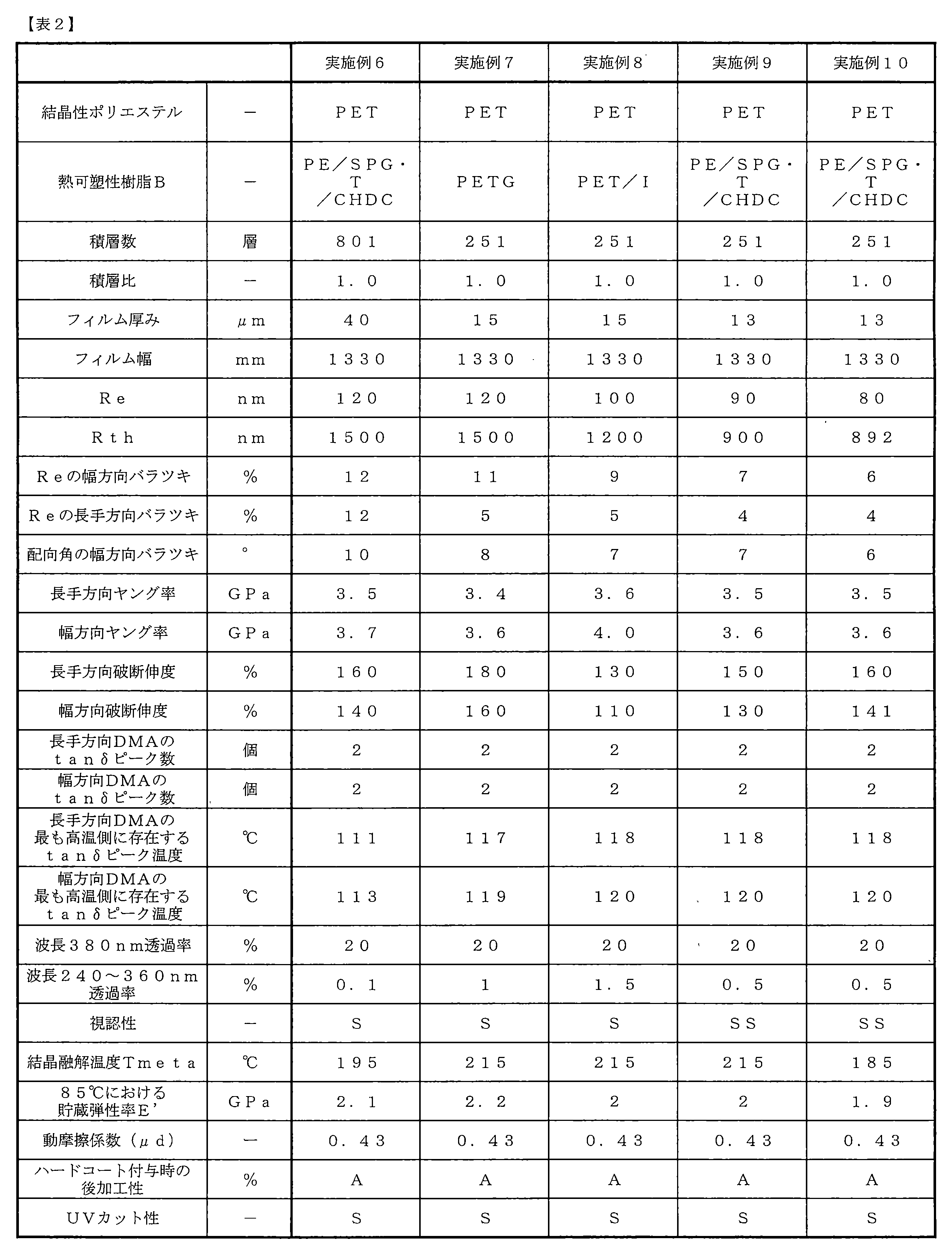
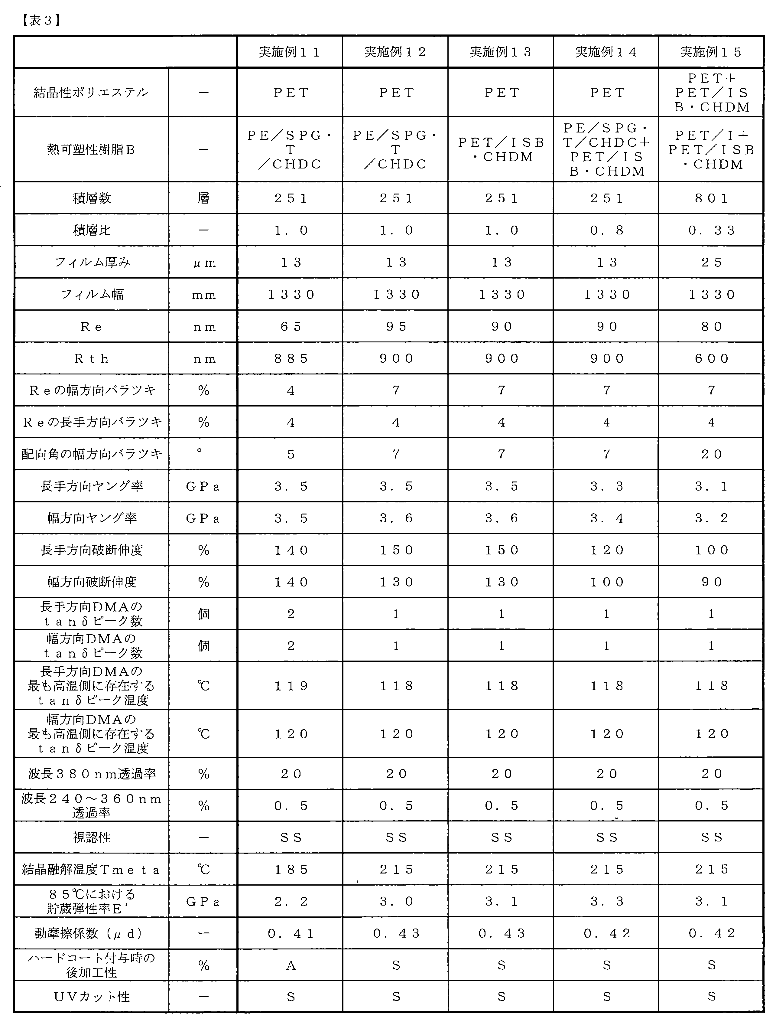
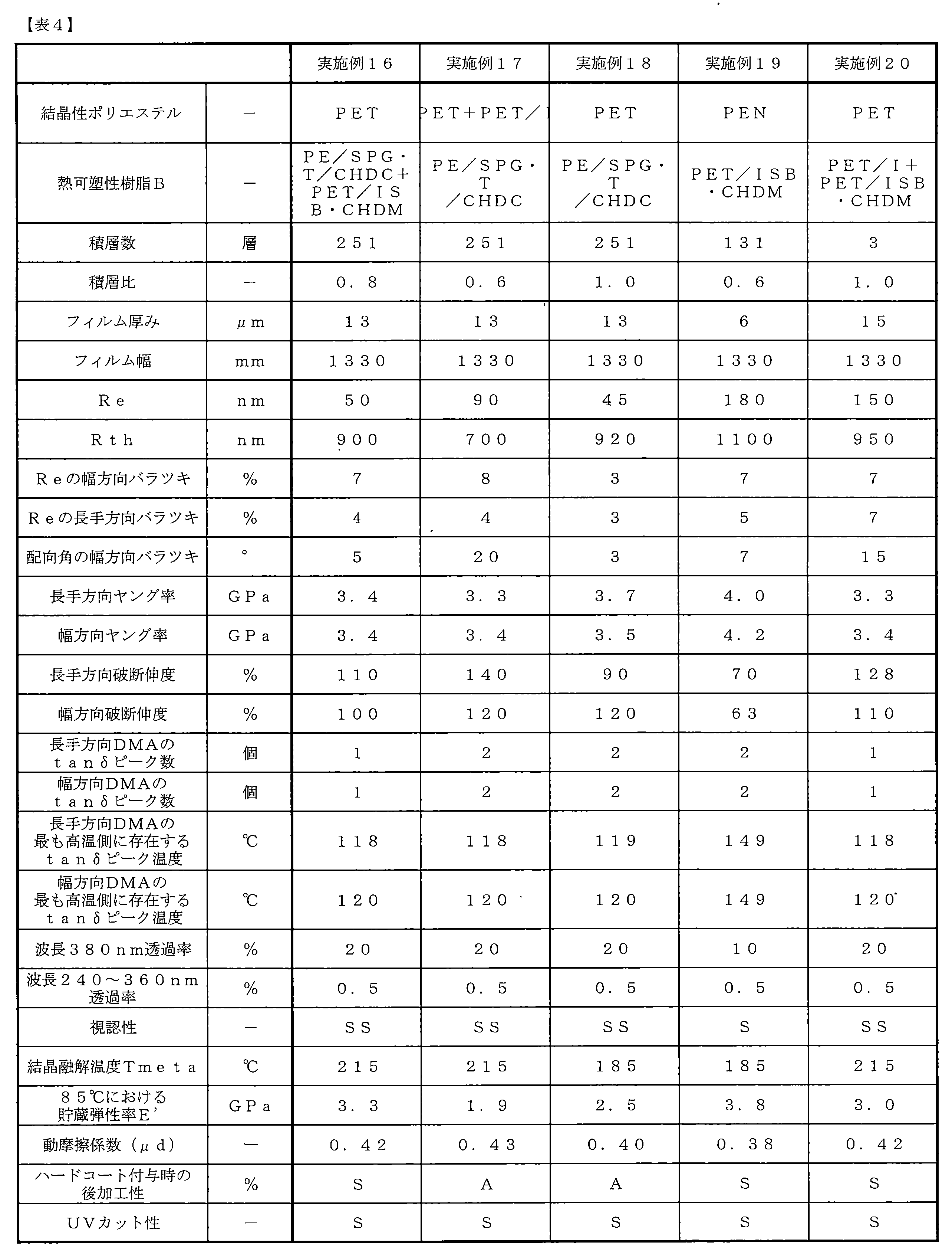
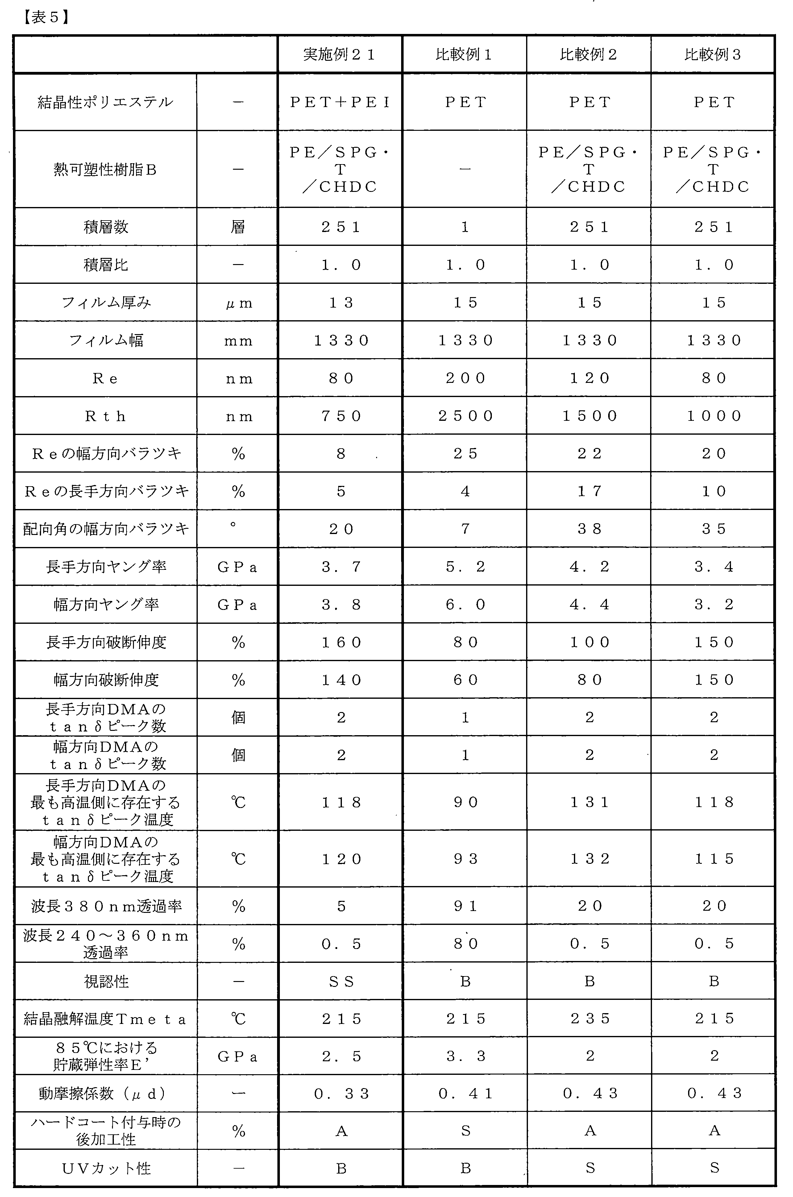
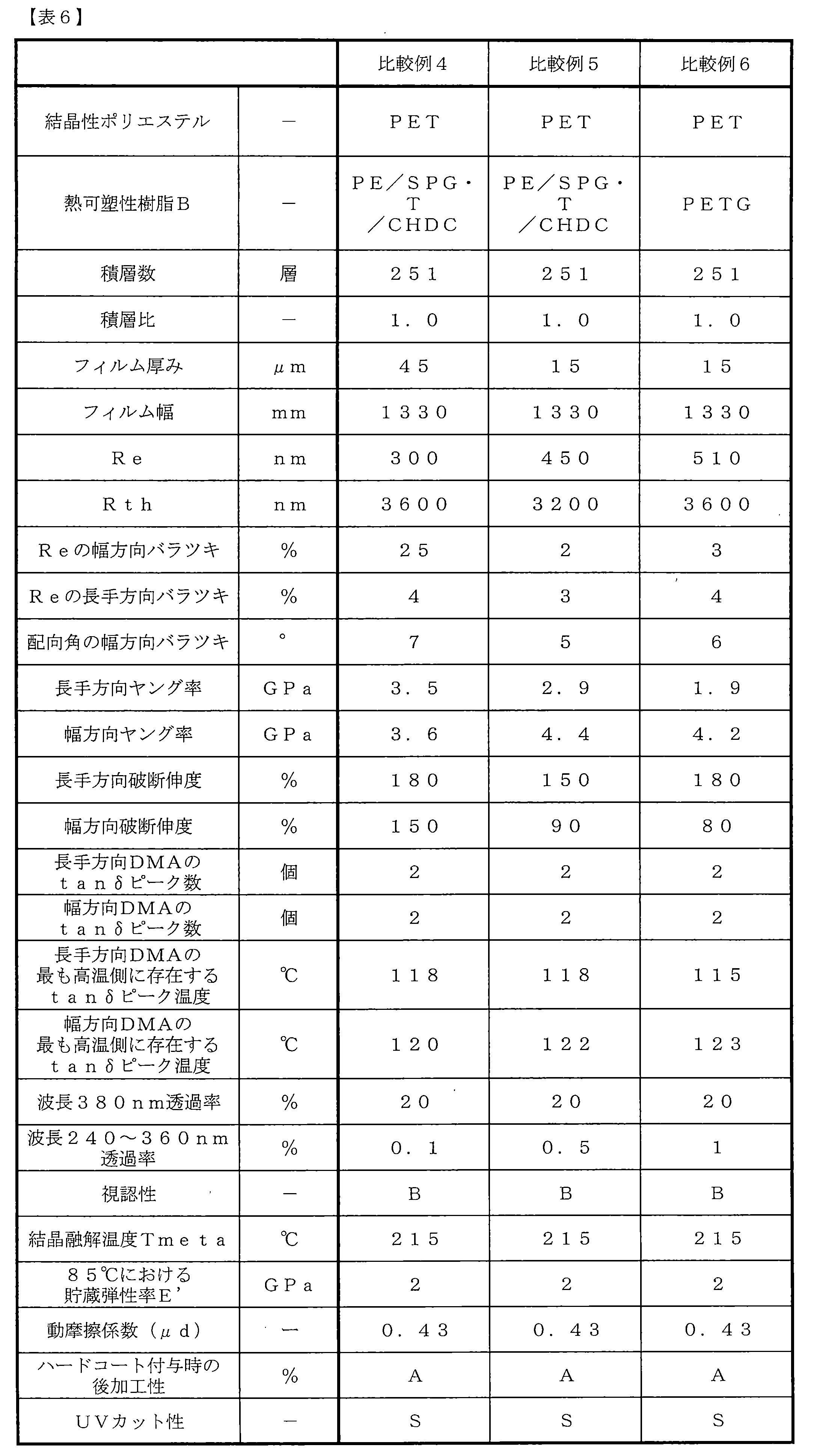
Claims (13)
- 厚み方向に3層以上積層された積層フィルムであって、面内方向位相差(Re)が0~400nm、厚み方向位相差(Rth)が0~1500nm、Reのバラツキが幅方向において18%以下、長手方向および幅方向のヤング率が2GPa以上、長手方向および幅方向の破断伸度が50%以上であり、該積層フィルムのフィルム厚みが40μm以下、フィルムの幅が400mm以上である積層フィルム。
- Reのバラツキが長手方向において20%以下である請求項1に記載の積層フィルム。
- 配向角のバラツキが幅方向において20°以下である請求項1または2に記載の積層フィルム。
- 結晶性ポリエステルを主成分とするA層と該結晶性ポリエステルとは異なる熱可塑性樹脂Bを主成分とするB層が交互に積層されてなる請求項1~3のいずれかに記載の積層フィルム。
- 熱可塑性樹脂Bがイソフタル酸、シクロヘキサンジカルボン酸、スピログリコール、シクロヘキサンジメタノール、およびイソソルビドから選ばれた共重合成分を一つ以上含む非晶性ポリエステルである請求項1~4のいずれかに記載の積層フィルム。
- 結晶部分融解温度Tmetaが190℃以下である請求項1~5のいずれかに記載の積層フィルム。
- 長手方向および/または幅方向の動的粘弾性測定においてtanδピークが2つ以上観測されることを特徴とする請求項1~6のいずれかに記載の積層フィルム。
- 動的粘弾性測定における85℃での貯蔵弾性率E’が2.5GPa以上である請求項1~7のいずれかに記載の積層フィルム。
- 積層数が51~1001層である請求項1~8のいずれかに記載の積層フィルム。
- 動摩擦係数0.45以下であり、少なくとも一方の面にプライマー層および/またはハードコート層が設けられている請求項1~9のいずれかに記載の積層フィルム。
- 偏光板保護フィルムとして用いられる請求項1~10のいずれかに記載の積層フィルム。
- ITO基材フィルムとして用いられる請求項1~10のいずれかに記載の積層フィルム。
- 積層フィルムの製造方法であって、前記積層フィルムが主に結晶性ポリエステルAと非晶性ポリエステルBから構成され、層数が3層以上であって、結晶性ポリエステルAからなるA層と非晶性ポリエステルBからなるB層の積層比(A/B)が2~0.2の未延伸フィルムを、延伸温度70~145℃の範囲で長手方向および幅方向の二軸延伸を行い、その後に温度120~235℃の範囲で熱固定を行い、その後に少なくとも長手方向に延伸温度80~150℃の範囲で1.02~1.95倍の再延伸を行い、その後に90~235℃の範囲で再び熱固定した後、巻き取ることを特徴とする請求項1に記載の積層フィルムの製造方法。
Priority Applications (3)
| Application Number | Priority Date | Filing Date | Title |
|---|---|---|---|
| KR1020177008289A KR102470780B1 (ko) | 2014-11-19 | 2015-11-16 | 적층 필름 |
| CN201580058517.9A CN107003458B (zh) | 2014-11-19 | 2015-11-16 | 叠层膜 |
| JP2015556881A JP6862654B2 (ja) | 2014-11-19 | 2015-11-16 | 積層フィルム |
Applications Claiming Priority (4)
| Application Number | Priority Date | Filing Date | Title |
|---|---|---|---|
| JP2014-234325 | 2014-11-19 | ||
| JP2014234325 | 2014-11-19 | ||
| JP2014-261815 | 2014-12-25 | ||
| JP2014261815 | 2014-12-25 |
Publications (1)
| Publication Number | Publication Date |
|---|---|
| WO2016080342A1 true WO2016080342A1 (ja) | 2016-05-26 |
Family
ID=56013879
Family Applications (1)
| Application Number | Title | Priority Date | Filing Date |
|---|---|---|---|
| PCT/JP2015/082107 Ceased WO2016080342A1 (ja) | 2014-11-19 | 2015-11-16 | 積層フィルム |
Country Status (5)
| Country | Link |
|---|---|
| JP (2) | JP6862654B2 (ja) |
| KR (1) | KR102470780B1 (ja) |
| CN (1) | CN107003458B (ja) |
| TW (1) | TWI670179B (ja) |
| WO (1) | WO2016080342A1 (ja) |
Cited By (14)
| Publication number | Priority date | Publication date | Assignee | Title |
|---|---|---|---|---|
| JP2017002307A (ja) * | 2015-06-15 | 2017-01-05 | 東レ株式会社 | ポリエステルフィルム、および偏光板保護フィルム |
| JP2018124367A (ja) * | 2017-01-31 | 2018-08-09 | 東レ株式会社 | 有機エレクトロルミネッセンス表示装置用フィルムおよび積層シート |
| JP2018126881A (ja) * | 2017-02-06 | 2018-08-16 | 三菱ケミカル株式会社 | 積層共重合ポリエステルフィルム |
| JP2018194741A (ja) * | 2017-05-19 | 2018-12-06 | 大日本印刷株式会社 | 配向フィルム、並びに、それを用いた透明導電性フィルム、タッチパネル及び表示装置 |
| JPWO2018070523A1 (ja) * | 2016-10-14 | 2019-08-08 | 大日本印刷株式会社 | 光学フィルムおよび画像表示装置 |
| WO2020045138A1 (ja) * | 2018-08-30 | 2020-03-05 | 日本ゼオン株式会社 | フィルム及びフィルムの製造方法 |
| JP2020042080A (ja) * | 2018-09-07 | 2020-03-19 | 東洋紡フイルムソリューション株式会社 | 多層積層フィルム、それを用いた輝度向上部材および偏光板 |
| JP2021157178A (ja) * | 2020-03-26 | 2021-10-07 | 東レ株式会社 | フィルム |
| WO2021200899A1 (ja) * | 2020-03-31 | 2021-10-07 | 大日本印刷株式会社 | 光学用のプラスチックフィルム、並びに、それを用いた光学積層体、偏光板及び画像表示装置 |
| US20220251314A1 (en) * | 2019-07-31 | 2022-08-11 | Toyobo Co., Ltd. | Biaxially oriented polyester film |
| US20240101770A1 (en) * | 2021-02-03 | 2024-03-28 | Toyobo Co., Ltd. | Biaxially oriented polyester film and production method therefor |
| JP2024145565A (ja) * | 2023-03-31 | 2024-10-15 | 日東電工株式会社 | 樹脂フィルム、位相差フィルムおよび樹脂フィルムの製造方法 |
| WO2025003850A1 (en) * | 2023-06-30 | 2025-01-02 | 3M Innovative Properties Company | Multilayer optical film |
| US12479992B2 (en) | 2021-02-03 | 2025-11-25 | Toyobo Co., Ltd. | Biaxially oriented polyester film and production method therefor |
Families Citing this family (4)
| Publication number | Priority date | Publication date | Assignee | Title |
|---|---|---|---|---|
| JPWO2022181583A1 (ja) * | 2021-02-24 | 2022-09-01 | ||
| CN114074467B (zh) * | 2021-11-18 | 2022-09-06 | 厦门长塑实业有限公司 | 一种具有炫彩金属质感的聚酰胺薄膜及其制备方法和其应用 |
| CN121969964A (zh) * | 2023-09-26 | 2026-05-01 | 3M创新有限公司 | 反射偏振器及其成形方法 |
| KR20250122764A (ko) * | 2024-02-07 | 2025-08-14 | 에스케이케미칼 주식회사 | 폴리에스테르 필름 |
Citations (14)
| Publication number | Priority date | Publication date | Assignee | Title |
|---|---|---|---|---|
| JP2001100006A (ja) * | 1999-09-29 | 2001-04-13 | Fuji Photo Film Co Ltd | 防眩性反射防止フィルムおよび画像表示装置 |
| JP2002361737A (ja) * | 2001-06-12 | 2002-12-18 | Toray Ind Inc | ポリエステルフィルムの製造方法及びポリエステルフィルム |
| JP2003154616A (ja) * | 2001-11-20 | 2003-05-27 | Teijin Dupont Films Japan Ltd | 積層フィルム及び表面保護フィルム |
| JP2003227932A (ja) * | 2002-02-04 | 2003-08-15 | Fuji Photo Film Co Ltd | 偏光板用保護フィルムの製造方法、偏光板、および画像表示装置 |
| JP2005103878A (ja) * | 2003-09-30 | 2005-04-21 | Nippon Zeon Co Ltd | 積層フィルムの製造方法 |
| JP2005134510A (ja) * | 2003-10-29 | 2005-05-26 | Toray Ind Inc | 位相差板および円偏光板 |
| JP2005181549A (ja) * | 2003-12-17 | 2005-07-07 | Nippon Zeon Co Ltd | 偏光板保護フィルム及びその製造方法 |
| JP2009029957A (ja) * | 2007-07-27 | 2009-02-12 | Daicel Chem Ind Ltd | 光学フィルム |
| JP2009160830A (ja) * | 2008-01-08 | 2009-07-23 | Toray Ind Inc | ポリエステル系積層フィルムおよび偏光板 |
| JP2009210850A (ja) * | 2008-03-05 | 2009-09-17 | Fujifilm Corp | 偏光板とその製造方法、および液晶表示装置 |
| JP2011141408A (ja) * | 2010-01-07 | 2011-07-21 | Toray Ind Inc | 偏光反射体 |
| JP2014048453A (ja) * | 2012-08-31 | 2014-03-17 | Toagosei Co Ltd | 加熱処理による低位相差光学フィルム又はシートの製造方法 |
| JP2014178519A (ja) * | 2013-03-15 | 2014-09-25 | Fujifilm Corp | セルロースアシレートフィルム、偏光板および液晶表示装置 |
| JP2014209162A (ja) * | 2013-03-28 | 2014-11-06 | 富士フイルム株式会社 | 偏光板及び画像表示装置 |
Family Cites Families (12)
| Publication number | Priority date | Publication date | Assignee | Title |
|---|---|---|---|---|
| KR100361611B1 (ko) * | 1994-08-30 | 2003-02-14 | 도레이 가부시끼가이샤 | 이축연신 폴리에스테르필름 및 그 제조방법 |
| AU2003207216A1 (en) * | 2002-02-21 | 2003-09-09 | Teijin Limited | Multilayered polyester film and process for producing the same |
| TWI268372B (en) * | 2004-03-26 | 2006-12-11 | Nitto Denko Corp | IPS mode liquid crystal display to realize a high contrast ratio over a wide range by laminating a polarizing plate and a retardation film to form an optical film |
| TWI345117B (en) * | 2006-11-28 | 2011-07-11 | Au Optronics Corp | Liquid crystal display apparatus |
| JP2009042653A (ja) | 2007-08-10 | 2009-02-26 | Mitsubishi Plastics Inc | 偏光膜保護用ポリエステルフィルム |
| JP2011039239A (ja) * | 2009-08-10 | 2011-02-24 | Sumitomo Chemical Co Ltd | 複合偏光板およびtnモード液晶パネル |
| EP2722695B1 (en) * | 2011-06-17 | 2015-11-18 | Teijin Limited | Reflective polarizing film, optical member for liquid crystal display device formed from same, and liquid crystal display device |
| JP2013020130A (ja) * | 2011-07-12 | 2013-01-31 | Keiwa Inc | ハードコートフィルム及びこれを用いたタッチパネル |
| JP2013210598A (ja) | 2012-03-01 | 2013-10-10 | Mitsubishi Plastics Inc | 偏光板保護用ポリエステルフィルム |
| US9527266B2 (en) * | 2012-03-16 | 2016-12-27 | Toray Industries, Inc. | Multi-layer laminated film |
| JP6225495B2 (ja) | 2012-06-08 | 2017-11-08 | 東レ株式会社 | 多層積層フィルムおよびこれを用いたガラス窓部材 |
| US9878523B2 (en) * | 2013-03-29 | 2018-01-30 | Toray Industries, Inc. | Laminated film |
-
2015
- 2015-11-16 CN CN201580058517.9A patent/CN107003458B/zh active Active
- 2015-11-16 KR KR1020177008289A patent/KR102470780B1/ko active Active
- 2015-11-16 WO PCT/JP2015/082107 patent/WO2016080342A1/ja not_active Ceased
- 2015-11-16 JP JP2015556881A patent/JP6862654B2/ja active Active
- 2015-11-18 TW TW104138070A patent/TWI670179B/zh active
-
2020
- 2020-08-07 JP JP2020134483A patent/JP6973584B2/ja active Active
Patent Citations (14)
| Publication number | Priority date | Publication date | Assignee | Title |
|---|---|---|---|---|
| JP2001100006A (ja) * | 1999-09-29 | 2001-04-13 | Fuji Photo Film Co Ltd | 防眩性反射防止フィルムおよび画像表示装置 |
| JP2002361737A (ja) * | 2001-06-12 | 2002-12-18 | Toray Ind Inc | ポリエステルフィルムの製造方法及びポリエステルフィルム |
| JP2003154616A (ja) * | 2001-11-20 | 2003-05-27 | Teijin Dupont Films Japan Ltd | 積層フィルム及び表面保護フィルム |
| JP2003227932A (ja) * | 2002-02-04 | 2003-08-15 | Fuji Photo Film Co Ltd | 偏光板用保護フィルムの製造方法、偏光板、および画像表示装置 |
| JP2005103878A (ja) * | 2003-09-30 | 2005-04-21 | Nippon Zeon Co Ltd | 積層フィルムの製造方法 |
| JP2005134510A (ja) * | 2003-10-29 | 2005-05-26 | Toray Ind Inc | 位相差板および円偏光板 |
| JP2005181549A (ja) * | 2003-12-17 | 2005-07-07 | Nippon Zeon Co Ltd | 偏光板保護フィルム及びその製造方法 |
| JP2009029957A (ja) * | 2007-07-27 | 2009-02-12 | Daicel Chem Ind Ltd | 光学フィルム |
| JP2009160830A (ja) * | 2008-01-08 | 2009-07-23 | Toray Ind Inc | ポリエステル系積層フィルムおよび偏光板 |
| JP2009210850A (ja) * | 2008-03-05 | 2009-09-17 | Fujifilm Corp | 偏光板とその製造方法、および液晶表示装置 |
| JP2011141408A (ja) * | 2010-01-07 | 2011-07-21 | Toray Ind Inc | 偏光反射体 |
| JP2014048453A (ja) * | 2012-08-31 | 2014-03-17 | Toagosei Co Ltd | 加熱処理による低位相差光学フィルム又はシートの製造方法 |
| JP2014178519A (ja) * | 2013-03-15 | 2014-09-25 | Fujifilm Corp | セルロースアシレートフィルム、偏光板および液晶表示装置 |
| JP2014209162A (ja) * | 2013-03-28 | 2014-11-06 | 富士フイルム株式会社 | 偏光板及び画像表示装置 |
Cited By (27)
| Publication number | Priority date | Publication date | Assignee | Title |
|---|---|---|---|---|
| JP2017002307A (ja) * | 2015-06-15 | 2017-01-05 | 東レ株式会社 | ポリエステルフィルム、および偏光板保護フィルム |
| JPWO2018070523A1 (ja) * | 2016-10-14 | 2019-08-08 | 大日本印刷株式会社 | 光学フィルムおよび画像表示装置 |
| JP2018124367A (ja) * | 2017-01-31 | 2018-08-09 | 東レ株式会社 | 有機エレクトロルミネッセンス表示装置用フィルムおよび積層シート |
| JP2018126881A (ja) * | 2017-02-06 | 2018-08-16 | 三菱ケミカル株式会社 | 積層共重合ポリエステルフィルム |
| JP2018194741A (ja) * | 2017-05-19 | 2018-12-06 | 大日本印刷株式会社 | 配向フィルム、並びに、それを用いた透明導電性フィルム、タッチパネル及び表示装置 |
| WO2020045138A1 (ja) * | 2018-08-30 | 2020-03-05 | 日本ゼオン株式会社 | フィルム及びフィルムの製造方法 |
| JP2020042080A (ja) * | 2018-09-07 | 2020-03-19 | 東洋紡フイルムソリューション株式会社 | 多層積層フィルム、それを用いた輝度向上部材および偏光板 |
| US12473408B2 (en) * | 2019-07-31 | 2025-11-18 | Toyobo Co., Ltd. | Biaxially oriented polyester film |
| EP4006087A4 (en) * | 2019-07-31 | 2023-08-09 | Toyobo Co., Ltd. | BIAXIALLY ORIENTED POLYESTER FILM |
| US20220251314A1 (en) * | 2019-07-31 | 2022-08-11 | Toyobo Co., Ltd. | Biaxially oriented polyester film |
| JP2021157178A (ja) * | 2020-03-26 | 2021-10-07 | 東レ株式会社 | フィルム |
| JP2023052737A (ja) * | 2020-03-31 | 2023-04-12 | 大日本印刷株式会社 | 光学用のプラスチックフィルム、並びに、それを用いた光学積層体、偏光板及び画像表示装置 |
| JP2023168344A (ja) * | 2020-03-31 | 2023-11-24 | 大日本印刷株式会社 | 光学用のプラスチックフィルム、並びに、それを用いた光学積層体、偏光板及び画像表示装置 |
| JPWO2021200899A1 (ja) * | 2020-03-31 | 2021-10-07 | ||
| CN116879993A (zh) * | 2020-03-31 | 2023-10-13 | 大日本印刷株式会社 | 光学用的塑料膜、以及使用了该塑料膜的光学层积体、偏振片和图像显示装置 |
| JP7371807B1 (ja) | 2020-03-31 | 2023-10-31 | 大日本印刷株式会社 | 光学用のプラスチックフィルム、並びに、それを用いた光学積層体、偏光板及び画像表示装置 |
| JP7371808B1 (ja) | 2020-03-31 | 2023-10-31 | 大日本印刷株式会社 | 光学用のプラスチックフィルム、並びに、それを用いた光学積層体、偏光板及び画像表示装置 |
| JP2023168345A (ja) * | 2020-03-31 | 2023-11-24 | 大日本印刷株式会社 | 光学用のプラスチックフィルム、並びに、それを用いた光学積層体、偏光板及び画像表示装置 |
| JP7211555B2 (ja) | 2020-03-31 | 2023-01-24 | 大日本印刷株式会社 | 光学用のプラスチックフィルム、並びに、それを用いた光学積層体、偏光板及び画像表示装置 |
| US11885734B2 (en) | 2020-03-31 | 2024-01-30 | Dai Nippon Printing Co., Ltd. | Optical plastic film, and optical laminate, polarization plate, and image |
| TWI834032B (zh) * | 2020-03-31 | 2024-03-01 | 日商大日本印刷股份有限公司 | 光學用之塑膠膜、以及使用其之光學積層體、偏光板及影像顯示裝置 |
| WO2021200899A1 (ja) * | 2020-03-31 | 2021-10-07 | 大日本印刷株式会社 | 光学用のプラスチックフィルム、並びに、それを用いた光学積層体、偏光板及び画像表示装置 |
| US12292373B2 (en) | 2020-03-31 | 2025-05-06 | Dai Nippon Printing Co., Ltd. | Optical plastic film, and optical laminate, polarization plate, and image display device using same |
| US20240101770A1 (en) * | 2021-02-03 | 2024-03-28 | Toyobo Co., Ltd. | Biaxially oriented polyester film and production method therefor |
| US12479992B2 (en) | 2021-02-03 | 2025-11-25 | Toyobo Co., Ltd. | Biaxially oriented polyester film and production method therefor |
| JP2024145565A (ja) * | 2023-03-31 | 2024-10-15 | 日東電工株式会社 | 樹脂フィルム、位相差フィルムおよび樹脂フィルムの製造方法 |
| WO2025003850A1 (en) * | 2023-06-30 | 2025-01-02 | 3M Innovative Properties Company | Multilayer optical film |
Also Published As
| Publication number | Publication date |
|---|---|
| TW201627144A (zh) | 2016-08-01 |
| JPWO2016080342A1 (ja) | 2017-08-31 |
| CN107003458A (zh) | 2017-08-01 |
| KR20170088331A (ko) | 2017-08-01 |
| TWI670179B (zh) | 2019-09-01 |
| CN107003458B (zh) | 2020-01-21 |
| JP6862654B2 (ja) | 2021-04-21 |
| JP6973584B2 (ja) | 2021-12-01 |
| KR102470780B1 (ko) | 2022-11-25 |
| JP2020192812A (ja) | 2020-12-03 |
Similar Documents
| Publication | Publication Date | Title |
|---|---|---|
| JP6973584B2 (ja) | 積層フィルム | |
| JP6884997B2 (ja) | ポリエステルフィルム、および偏光板保護フィルム | |
| JP6361400B2 (ja) | 二軸延伸ポリエステルフィルム、それを用いた偏光板、液晶ディスプレイ | |
| JP6365300B2 (ja) | 積層フィルムおよび偏光板 | |
| WO2014156726A1 (ja) | 積層フィルム | |
| JP2017206012A (ja) | 積層フィルムおよびそれを用いた液晶投影用合わせガラス | |
| JP2016141058A (ja) | 二軸配向ポリエステルフィルムおよびその製造方法 | |
| TWI730966B (zh) | 多層積層薄膜 | |
| JP6225495B2 (ja) | 多層積層フィルムおよびこれを用いたガラス窓部材 | |
| JP6172027B2 (ja) | ディスプレイ用フィルム | |
| TW201637843A (zh) | 積層薄膜及其製造方法 | |
| JP6291830B2 (ja) | 多層積層フィルム | |
| JP6992259B2 (ja) | 積層フィルムおよびその製造方法 | |
| JP6476795B2 (ja) | 積層フィルム | |
| JP2017061145A (ja) | 積層フィルム、フィルムロール及びその製造方法 | |
| JP2022025942A (ja) | 偏光子保護用ポリエステルフィルム、および該ポリエステルフィルムを含む偏光板 | |
| JP2022025943A (ja) | 偏光子保護用ポリエステルフィルム、および該ポリエステルフィルムを含む偏光板 | |
| JP6848561B2 (ja) | 積層フィルム | |
| JP2017177350A (ja) | 積層フィルム | |
| JP2022025941A (ja) | 偏光子保護用ポリエステルフィルム、および該ポリエステルフィルムを含む偏光板 | |
| JP6543964B2 (ja) | 積層フィルム及びその製造方法 | |
| JP2018039263A (ja) | 積層フィルムおよびフィルムロール |
Legal Events
| Date | Code | Title | Description |
|---|---|---|---|
| ENP | Entry into the national phase |
Ref document number: 2015556881 Country of ref document: JP Kind code of ref document: A |
|
| 121 | Ep: the epo has been informed by wipo that ep was designated in this application |
Ref document number: 15862009 Country of ref document: EP Kind code of ref document: A1 |
|
| ENP | Entry into the national phase |
Ref document number: 20177008289 Country of ref document: KR Kind code of ref document: A |
|
| NENP | Non-entry into the national phase |
Ref country code: DE |
|
| 122 | Ep: pct application non-entry in european phase |
Ref document number: 15862009 Country of ref document: EP Kind code of ref document: A1 |