WO2016017718A1 - ターボ冷凍機及びその制御装置並びにその制御方法 - Google Patents
ターボ冷凍機及びその制御装置並びにその制御方法 Download PDFInfo
- Publication number
- WO2016017718A1 WO2016017718A1 PCT/JP2015/071559 JP2015071559W WO2016017718A1 WO 2016017718 A1 WO2016017718 A1 WO 2016017718A1 JP 2015071559 W JP2015071559 W JP 2015071559W WO 2016017718 A1 WO2016017718 A1 WO 2016017718A1
- Authority
- WO
- WIPO (PCT)
- Prior art keywords
- temperature
- expansion valve
- condensation
- heat source
- source water
- Prior art date
Links
Images


Classifications
-
- F—MECHANICAL ENGINEERING; LIGHTING; HEATING; WEAPONS; BLASTING
- F25—REFRIGERATION OR COOLING; COMBINED HEATING AND REFRIGERATION SYSTEMS; HEAT PUMP SYSTEMS; MANUFACTURE OR STORAGE OF ICE; LIQUEFACTION SOLIDIFICATION OF GASES
- F25B—REFRIGERATION MACHINES, PLANTS OR SYSTEMS; COMBINED HEATING AND REFRIGERATION SYSTEMS; HEAT PUMP SYSTEMS
- F25B1/00—Compression machines, plants or systems with non-reversible cycle
- F25B1/04—Compression machines, plants or systems with non-reversible cycle with compressor of rotary type
- F25B1/053—Compression machines, plants or systems with non-reversible cycle with compressor of rotary type of turbine type
-
- F—MECHANICAL ENGINEERING; LIGHTING; HEATING; WEAPONS; BLASTING
- F24—HEATING; RANGES; VENTILATING
- F24H—FLUID HEATERS, e.g. WATER OR AIR HEATERS, HAVING HEAT-GENERATING MEANS, e.g. HEAT PUMPS, IN GENERAL
- F24H4/00—Fluid heaters characterised by the use of heat pumps
- F24H4/02—Water heaters
-
- F—MECHANICAL ENGINEERING; LIGHTING; HEATING; WEAPONS; BLASTING
- F25—REFRIGERATION OR COOLING; COMBINED HEATING AND REFRIGERATION SYSTEMS; HEAT PUMP SYSTEMS; MANUFACTURE OR STORAGE OF ICE; LIQUEFACTION SOLIDIFICATION OF GASES
- F25B—REFRIGERATION MACHINES, PLANTS OR SYSTEMS; COMBINED HEATING AND REFRIGERATION SYSTEMS; HEAT PUMP SYSTEMS
- F25B40/00—Subcoolers, desuperheaters or superheaters
- F25B40/02—Subcoolers
-
- F—MECHANICAL ENGINEERING; LIGHTING; HEATING; WEAPONS; BLASTING
- F25—REFRIGERATION OR COOLING; COMBINED HEATING AND REFRIGERATION SYSTEMS; HEAT PUMP SYSTEMS; MANUFACTURE OR STORAGE OF ICE; LIQUEFACTION SOLIDIFICATION OF GASES
- F25B—REFRIGERATION MACHINES, PLANTS OR SYSTEMS; COMBINED HEATING AND REFRIGERATION SYSTEMS; HEAT PUMP SYSTEMS
- F25B41/00—Fluid-circulation arrangements
- F25B41/30—Expansion means; Dispositions thereof
- F25B41/31—Expansion valves
-
- F—MECHANICAL ENGINEERING; LIGHTING; HEATING; WEAPONS; BLASTING
- F25—REFRIGERATION OR COOLING; COMBINED HEATING AND REFRIGERATION SYSTEMS; HEAT PUMP SYSTEMS; MANUFACTURE OR STORAGE OF ICE; LIQUEFACTION SOLIDIFICATION OF GASES
- F25B—REFRIGERATION MACHINES, PLANTS OR SYSTEMS; COMBINED HEATING AND REFRIGERATION SYSTEMS; HEAT PUMP SYSTEMS
- F25B49/00—Arrangement or mounting of control or safety devices
- F25B49/02—Arrangement or mounting of control or safety devices for compression type machines, plants or systems
-
- F—MECHANICAL ENGINEERING; LIGHTING; HEATING; WEAPONS; BLASTING
- F25—REFRIGERATION OR COOLING; COMBINED HEATING AND REFRIGERATION SYSTEMS; HEAT PUMP SYSTEMS; MANUFACTURE OR STORAGE OF ICE; LIQUEFACTION SOLIDIFICATION OF GASES
- F25B—REFRIGERATION MACHINES, PLANTS OR SYSTEMS; COMBINED HEATING AND REFRIGERATION SYSTEMS; HEAT PUMP SYSTEMS
- F25B2400/00—General features or devices for refrigeration machines, plants or systems, combined heating and refrigeration systems or heat-pump systems, i.e. not limited to a particular subgroup of F25B
- F25B2400/04—Refrigeration circuit bypassing means
- F25B2400/0417—Refrigeration circuit bypassing means for the subcooler
-
- F—MECHANICAL ENGINEERING; LIGHTING; HEATING; WEAPONS; BLASTING
- F25—REFRIGERATION OR COOLING; COMBINED HEATING AND REFRIGERATION SYSTEMS; HEAT PUMP SYSTEMS; MANUFACTURE OR STORAGE OF ICE; LIQUEFACTION SOLIDIFICATION OF GASES
- F25B—REFRIGERATION MACHINES, PLANTS OR SYSTEMS; COMBINED HEATING AND REFRIGERATION SYSTEMS; HEAT PUMP SYSTEMS
- F25B2600/00—Control issues
- F25B2600/01—Timing
-
- F—MECHANICAL ENGINEERING; LIGHTING; HEATING; WEAPONS; BLASTING
- F25—REFRIGERATION OR COOLING; COMBINED HEATING AND REFRIGERATION SYSTEMS; HEAT PUMP SYSTEMS; MANUFACTURE OR STORAGE OF ICE; LIQUEFACTION SOLIDIFICATION OF GASES
- F25B—REFRIGERATION MACHINES, PLANTS OR SYSTEMS; COMBINED HEATING AND REFRIGERATION SYSTEMS; HEAT PUMP SYSTEMS
- F25B2600/00—Control issues
- F25B2600/25—Control of valves
- F25B2600/2513—Expansion valves
-
- F—MECHANICAL ENGINEERING; LIGHTING; HEATING; WEAPONS; BLASTING
- F25—REFRIGERATION OR COOLING; COMBINED HEATING AND REFRIGERATION SYSTEMS; HEAT PUMP SYSTEMS; MANUFACTURE OR STORAGE OF ICE; LIQUEFACTION SOLIDIFICATION OF GASES
- F25B—REFRIGERATION MACHINES, PLANTS OR SYSTEMS; COMBINED HEATING AND REFRIGERATION SYSTEMS; HEAT PUMP SYSTEMS
- F25B2700/00—Sensing or detecting of parameters; Sensors therefor
- F25B2700/19—Pressures
- F25B2700/195—Pressures of the condenser
-
- F—MECHANICAL ENGINEERING; LIGHTING; HEATING; WEAPONS; BLASTING
- F25—REFRIGERATION OR COOLING; COMBINED HEATING AND REFRIGERATION SYSTEMS; HEAT PUMP SYSTEMS; MANUFACTURE OR STORAGE OF ICE; LIQUEFACTION SOLIDIFICATION OF GASES
- F25B—REFRIGERATION MACHINES, PLANTS OR SYSTEMS; COMBINED HEATING AND REFRIGERATION SYSTEMS; HEAT PUMP SYSTEMS
- F25B2700/00—Sensing or detecting of parameters; Sensors therefor
- F25B2700/21—Temperatures
- F25B2700/2116—Temperatures of a condenser
- F25B2700/21162—Temperatures of a condenser of the refrigerant at the inlet of the condenser
-
- F—MECHANICAL ENGINEERING; LIGHTING; HEATING; WEAPONS; BLASTING
- F25—REFRIGERATION OR COOLING; COMBINED HEATING AND REFRIGERATION SYSTEMS; HEAT PUMP SYSTEMS; MANUFACTURE OR STORAGE OF ICE; LIQUEFACTION SOLIDIFICATION OF GASES
- F25B—REFRIGERATION MACHINES, PLANTS OR SYSTEMS; COMBINED HEATING AND REFRIGERATION SYSTEMS; HEAT PUMP SYSTEMS
- F25B2700/00—Sensing or detecting of parameters; Sensors therefor
- F25B2700/21—Temperatures
- F25B2700/2116—Temperatures of a condenser
- F25B2700/21163—Temperatures of a condenser of the refrigerant at the outlet of the condenser
Definitions
- the present invention relates to a turbo chiller, a control device thereof, and a control method thereof.
- the turbo refrigerator 100 includes a main circuit of a refrigeration cycle in which a two-stage turbo compressor 102, a condenser 103, an economizer 104, a main expansion valve 105, and an evaporator 107 are sequentially connected.
- the gas refrigerant compressed in the turbo compressor 102 and having a high temperature and high pressure is sent to the condenser 103.
- the condenser 103 is a plate heat exchanger, and heats the hot water up to a predetermined temperature by exchanging heat between the hot water circulating in the hot water circuit 111 and the gas refrigerant.
- the refrigerant condensed and liquefied in the condenser 103 is supplied to the economizer 104.
- the economizer 104 exchanges heat between the liquid refrigerant from the condenser 103 (a liquefied refrigerant flowing in the main circuit) and the refrigerant diverted from the main circuit and depressurized by the sub-expansion valve 113, and the main circuit uses the latent heat of vaporization of the refrigerant.
- It is a plate type refrigerant / refrigerant heat exchanger for supercooling a liquid refrigerant flowing inside.
- the economizer 104 includes a gas circuit for injecting the gas refrigerant evaporated by supercooling the liquid refrigerant into the intermediate-pressure compressed refrigerant from the intermediate suction port 102C of the two-stage turbo compressor 102.
- the main expansion valve 105 expands the supercooled refrigerant through the economizer 104 and supplies it to the evaporator 107.
- the evaporator 107 is a plate-type heat exchanger, and evaporates the refrigerant by exchanging heat between the refrigerant led from the main expansion valve 105 and the heat source water circulated through the heat source water circuit 115, and the latent heat of evaporation causes the refrigerant to evaporate. Cool the heat source water.
- thermometer 131 As measuring means for measuring the temperature and pressure of the refrigerant, hot water and heat source water, pressure gauges 141, 142, 143 and thermometer 131 are provided in the suction port 102A, the discharge port 102B and the intermediate suction port 102C of the two-stage turbo compressor 2. 132, 133, thermometers 135, 136, 137, 138 are respectively provided at the inlet and outlet of the hot water circuit 111 and at the inlet and outlet of the heat source water circuit 15, and at the inlet of the main expansion valve 105, respectively. A thermometer 134 is provided.
- FIG. 10 shows a configuration example of a thermometer.
- FIG. 10A shows an example in which a resistance temperature detector with a protective tube (a thermometer having a double structure) is inserted into the pipe
- FIG. 10B shows the temperature by welding a thermometer to the outer wall of the pipe. It shows an example of indirectly measuring.
- the response of a thermometer is bad as mentioned above, the following problems arise. For example, taking the turbo chiller 100 shown in FIG.
- An object of the present invention is to provide a turbo chiller, a control device therefor, and a control method that can alleviate a control delay of an expansion valve caused by a measurement delay of a thermometer.
- a first aspect of the present invention includes a main circuit of a refrigeration cycle in which a compressor, a condenser, an expansion valve, and an evaporator are sequentially connected to circulate a refrigerant, and an inlet temperature of a heat medium flowing into the condenser. It is applied to a turbo chiller comprising first temperature measuring means for measuring the temperature, second temperature measuring means for measuring the outlet temperature of the heat medium flowing out from the condenser, and pressure measuring means for measuring the condensation pressure. A control device for correcting the temperature measured by the first temperature measuring means and the second temperature measuring means; and the heat medium inlet temperature and the heat medium outlet temperature corrected by the temperature correcting means.
- An expansion valve control means for controlling the opening degree of the expansion valve, and the temperature correction means includes a condensation temperature acquisition means for acquiring a condensation temperature from the condensation pressure acquired by the pressure measurement means, and a current Whether the condensation temperature
- the condensation temperature based on the condensation pressure is acquired by the condensation temperature acquisition means, and the temperature difference between the current condensation temperature and the condensation temperature before a certain period is calculated by the temperature difference calculation means. The Then, it is determined by the determining means whether the absolute value of the temperature difference is equal to or greater than a predetermined threshold value.
- the first temperature measuring means and the second temperature measurement are corrected by the correcting means.
- the temperature is corrected by adding a temperature difference to each temperature measured by the means. Thereby, it becomes possible to catch a temperature change early, and it becomes possible to relieve the measurement delay of a temperature measurement means.
- the control of the expansion valve using the corrected temperature is performed by the expansion valve control means, so that the control delay of the expansion valve due to the measurement delay by the first temperature measuring means and the second temperature measuring means is reduced. Is possible.
- the certain period may be set to a period in which the refrigerant makes a round of the main circuit.
- turbo chiller control device it is possible to accurately grasp the fluctuation of the inlet temperature of the heat medium.
- the turbo chiller control device is provided between the condenser and the expansion valve, and exchanges heat between the liquid refrigerant flowing through the main circuit and the refrigerant diverted from the main circuit and decompressed by the sub expansion valve.
- the expansion valve control means may perform opening control of the sub expansion valve using the heat medium inlet temperature and the heat medium outlet temperature corrected by the temperature correction means.
- the sub-expansion valve is controlled using the corrected temperature, so that the sub-expansion valve is controlled due to the measurement delay by the first temperature measuring means and the second temperature measuring means. It becomes possible to reduce the delay.
- a compressor, a condenser, an expansion valve, and an evaporator are sequentially connected, a main circuit of a refrigeration cycle in which refrigerant circulates, and an inlet temperature of heat source water flowing into the evaporator
- an expansion valve control means for controlling the opening of the expansion valve using the evaporation pressure obtained from the evaporation temperature corrected by the evaporation temperature correction means.
- the ratio of the value obtained by subtracting the evaporation temperature from the heat source water inlet temperature to the value obtained by subtracting the heat source water inlet temperature from the heat source water outlet temperature by the evaporation temperature correction means is stable.
- An evaporation temperature that matches the target ratio is calculated. Then, by reflecting the evaporation temperature calculated by the evaporation temperature correction means in the valve opening control of the expansion valve, it is possible to avoid the valve opening of the expansion valve from becoming excessive.
- a third aspect of the present invention is a turbo refrigerator provided with the above-described control device.
- a compressor, a condenser, an expansion valve, and an evaporator are sequentially connected, a main circuit of a refrigeration cycle in which refrigerant circulates, and an inlet temperature of the heat medium flowing into the condenser It is applied to a turbo chiller comprising first temperature measuring means for measuring the temperature, second temperature measuring means for measuring the outlet temperature of the heat medium flowing out from the condenser, and pressure measuring means for measuring the condensation pressure.
- An expansion valve control step for controlling the opening of the expansion valve, and the temperature correction step includes a condensing temperature acquisition step for acquiring a condensing temperature from the condensing pressure acquired by the pressure measuring means, and a current Whether the condensation temperature
- a compressor, a condenser, an expansion valve, and an evaporator are sequentially connected, a main circuit of a refrigeration cycle in which refrigerant circulates, and an inlet temperature of heat source water that flows into the evaporator
- an expansion valve control step for controlling the opening of the expansion valve using the evaporation pressure obtained from the evaporation temperature corrected in the evaporation temperature correction step.
- FIG. 1 is a diagram showing a schematic configuration of a turbo refrigerator according to the first embodiment of the present invention.
- a turbo refrigerator 1 includes a closed circuit refrigerant main circuit 8 in which a compressor 2, a condenser 3, an economizer 4, a main expansion valve 5, and an evaporator 7 are sequentially connected. I have.
- the compressor 2 is a multistage centrifugal compressor that is driven by an inverter motor 6.
- the compressor 2 has an intermediate suction port 2C provided between the first impeller and the second impeller.
- the low-pressure gas refrigerant sucked from the suction port 2A is sequentially centrifugally compressed by the rotation of the first impeller and the second impeller, and the compressed high-pressure gas refrigerant is discharged from the discharge port 2B.
- the high-pressure gas refrigerant discharged from the discharge port 2 ⁇ / b> B of the compressor 2 is guided to the condenser 3.
- the condenser 3 is, for example, a plate heat exchanger, and exchanges heat between the high-pressure gas refrigerant supplied from the compressor 2 and hot water (heat medium) circulating in the hot water circuit, whereby the hot water is reduced to a predetermined temperature. Raise the temperature.
- the refrigerant condensed and liquefied in the condenser 3 is supplied to the economizer 4.
- the economizer 4 exchanges heat between the liquid refrigerant that flows in the refrigerant main circuit 8 and the refrigerant that is diverted from the refrigerant main circuit 8 and decompressed by the sub-expansion valve 9, and the refrigerant main circuit 8 is generated by the latent heat of vaporization of the refrigerant after decompression. It is a plate type refrigerant / refrigerant heat exchanger for supercooling a liquid refrigerant flowing inside.
- the economizer 4 includes a gas circuit 10 for injecting a gas refrigerant (intermediate pressure refrigerant) evaporated by supercooling the liquid refrigerant into an intermediate pressure compressed refrigerant from the intermediate suction port 2C of the compressor 2. Constitutes an intermediate cooler type economizer cycle.
- the refrigerant supercooled through the economizer 4 is expanded by passing through the main expansion valve 5 and supplied to the evaporator 7.
- the evaporator 7 is a heat exchanger (for example, a plate heat exchanger), and evaporates the refrigerant by exchanging heat between the refrigerant introduced from the main expansion valve 5 and the heat source water circulating in the heat source water circuit 15.
- the heat source water is cooled by the latent heat of evaporation.
- the turbo refrigerator 1 includes a temperature sensor 12 that measures a hot water inlet temperature Thwi that is the temperature of hot water flowing into the condenser 3, and a temperature sensor 13 that measures a hot water outlet temperature Thwo that is the temperature of hot water that flows out of the condenser 3.
- the temperature sensor 14 is provided on the refrigerant outlet side of the condenser 3 and measures the condenser outlet temperature Tc.
- the temperature sensor 14 is provided between the ecomizer 4 and the main expansion valve 5 in the refrigerant main circuit 8 to set the main expansion valve inlet temperature Tecoh.
- the temperature sensor 19 to be measured, the temperature sensor 16 to measure the intermediate pressure refrigerant temperature Tm that is the temperature of the intermediate pressure refrigerant flowing through the gas circuit 10, and the heat source water inlet temperature Tswi that is the temperature of the heat source water flowing into the evaporator 7 are measured.
- the temperature sensor 17 and the temperature sensor 18 that measures the heat source water outlet temperature Tswo, which is the temperature of the heat source water flowing out from the evaporator 7, are provided.
- the turbo refrigerator 1 includes a pressure sensor 20 that measures a condensation pressure (compressor discharge pressure) Pd, a pressure sensor 21 that measures an intermediate pressure refrigerant pressure Pm that is a pressure of an intermediate pressure refrigerant flowing through the gas circuit 10, and an evaporation pressure (compression).
- a pressure sensor 22 for measuring the machine suction pressure (Ps) is provided.
- the measurement values of the various sensors are transmitted to the control device 30 and used for compressor speed control, opening control of the main expansion valve 5 and the sub-expansion valve 9, and the like.
- the control device 30 is, for example, a computer, and communicates with a main storage device such as a CPU (Central Processing Unit) and a RAM (Random Access Memory), an auxiliary storage device, and an external device to communicate information.
- Equipment a main storage device such as a CPU (Central Processing Unit) and a RAM (Random Access Memory), an auxiliary storage device, and an external device to communicate information.
- Equipment The auxiliary storage device is a computer-readable recording medium, such as a magnetic disk, a magneto-optical disk, a CD-ROM, a DVD-ROM, or a semiconductor memory.
- Various programs are stored in the auxiliary storage device, and various processes are realized by the CPU reading and executing the program from the auxiliary storage device to the main storage device.
- FIG. 2 is a functional block diagram of the control device 30.
- the control device 30 includes a temperature correction unit 31 and an expansion valve control unit 32.
- the temperature correction unit 31 corrects the hot water inlet temperature Thwi and the hot water outlet temperature Thwo. That is, as described above, a measurement delay occurs in the temperature sensors 12, 13 and the like.
- the temperature correction unit 31 is a configuration for correcting a measurement delay caused by the temperature sensors 12 and 13.
- the temperature control unit 31 includes a condensation temperature acquisition unit 41, a temperature difference calculation unit 42, a determination unit 43, and a correction unit 44.
- the condensation temperature acquisition unit 41 acquires the condensation temperature Tc from the condensation pressure Pd measured by the pressure sensor 20. Specifically, the condensing temperature acquisition unit 41 has correspondence information (function or table) in which the condensing pressure Pd and the condensing temperature CT are uniquely associated, and the condensing pressure Pd is used using this correspondence information. To obtain the condensation temperature CT.
- the temperature difference calculation unit 42 calculates the temperature difference ⁇ CT by subtracting the condensation temperature obtained before a certain period from the current condensation temperature obtained by the condensation temperature acquisition unit 41.
- the fixed period corresponds to, for example, a period in which the refrigerant makes a round of the refrigerant main circuit 8, and is obtained by dividing the refrigerant charging amount [kg] by the refrigerant circulation amount [kg / min].
- a period in which a predetermined margin (margin) is taken into consideration for this value may be a fixed period.
- the determination unit 43 determines whether or not the absolute value
- the threshold is, for example, a value derived from a change rate determined by the specification of the main expansion valve 5.
- the change rate of the main expansion valve 5 is 10 [%] / 60 [sec] at the maximum
- the hot water inlet temperature Thwi is about 70 [° C.]
- the hot water outlet temperature Thwo is 80 [° C.]
- the above-mentioned fixed period is 30 [sec]. Is determined by the following equation (1).
- ⁇ is a margin (margin), which may be a fixed value or a value determined according to the value in parentheses in the above equation (1).
- the correction unit 44 adds the temperature difference ⁇ CT to the hot water inlet temperature Thwi and the hot water outlet temperature Thwo, thereby setting the hot water inlet temperature Thwi and the hot water outlet temperature Thwo. to correct.
- the expansion valve control unit 32 calculates the expansion valve opening using the corrected hot water inlet temperature Thwi and the corrected hot water outlet temperature Thwo during the period in which the temperature correction is performed by the temperature correction unit 31, During a period when the temperature is not corrected by the temperature correction unit 31, the expansion valve opening is calculated using the hot water inlet temperature Thwi and the hot water outlet temperature Thwo measured by the temperature sensors 12 and 13.
- the expansion valve control unit 32 will be described.
- the expansion valve control unit 32 includes, for example, a current flow rate calculation unit 51, a set flow rate calculation unit 52, a main expansion valve opening degree calculation unit 53, and a sub expansion valve opening degree calculation unit 54.
- the expansion valve control is not limited to the method shown below, and various known control methods can be employed. In this case, when the hot water inlet temperature Thwi and the hot water outlet temperature Thwo are used as parameters, if the temperature correction unit 31 performs temperature correction, the corrected hot water inlet temperature Thwi and hot water outlet are corrected.
- the temperature Thwo shall be used.
- the current flow rate calculation unit 51 performs flow rate calculation using the hot water inlet temperature Thwi and the hot water outlet temperature Thwo as parameters.
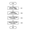
- FIG. 3 shows a flowchart of processing executed by the current flow rate calculation unit 51.
- the current flow rate calculation unit 51 calculates the current heating capacity Qcon [kW] using the hot water inlet temperature Thwi and the hot water outlet Thwo (step SA1).
- the condenser flow rate Gcon [kg / s] is calculated using the following equation (2) (step SA2).
- Hd is the discharge enthalpy [kJ / kg]
- Hc is the condenser outlet enthalpy [kJ / kg].
- Geva (Gcon-Gmo-Goc) / (1 + x) (3)
- x (Hc ⁇ Hecoh) / (Hecom ⁇ Hc) (4)
- Equation (3) Gcon is a condenser flow rate [kg / s]
- Gmo is a motor cooling flow rate [kg / s]
- Goc is an oil cooling refrigerant flow rate [kg / s].
- Hc is the condenser outlet enthalpy [kJ / kg]
- Hecoh is the main expansion valve inlet enthalpy [kJ / kg]
- Hecom is the intermediate suction gas enthalpy [kJ / kg].
- the current flow rate calculation unit 51 calculates the current flow rate Geco of the sub expansion valve 9 using the condenser flow rate Gcon (step SA4). Specifically, the calculation is performed using the following equation (5).
- x is as described in the above equation (4).
- Geva is the current flow rate Geva of the main expansion valve calculated in the above equation (3).
- the current flow rate Geva of the main expansion valve and the current flow rate Geco of the sub expansion valve calculated in this way are output to the main expansion valve opening degree calculation unit 53 and the sub expansion valve opening degree calculation unit 54.
- the set flow rate calculation unit 52 calculates the set flow rate Geva * of the main expansion valve 5 and the set flow rate Geco * of the sub expansion valve 9.
- the calculation by the set flow rate calculation unit 52 differs only in that the preset hot water outlet set temperature Thwo * is used instead of the hot water outlet temperature Thwo in the calculation formula used in the current flow rate calculation unit 51 described above. The others are the same. Therefore, detailed description is omitted.
- the set flow rate Geva * of the main expansion valve 5 and the set flow rate Geco * of the sub expansion valve 9 are output to the main expansion valve opening calculation unit 53 and the sub expansion valve opening calculation unit 54.
- the main expansion valve opening degree calculation unit 53 includes the current flow rate Geva of the main expansion valve 5 calculated by the current flow rate calculation unit 51, the current flow rate Geco of the sub expansion valve 9, and the main expansion valve 5 set by the set flow rate calculation unit 52.
- the feedforward opening degree command is calculated by performing feedforward control using the set flow rate Geva * of the sub-expansion valve 9 and the set flow rate Geco * of the sub-expansion valve 9, and the feedback opening degree by performing feedback control using the evaporator end temperature. By calculating the command and adding them together, an opening command is generated.
- FIG. 4 is a flowchart showing processing executed by the main expansion valve opening degree calculation unit 53.
- the set opening Cveva * of the main expansion valve is calculated using the set flow rate Geva * of the main expansion valve 5 and the differential pressure ⁇ P2 as parameters (step SB2).
- an opening degree command OP_FF in the feedforward control is calculated by apportioning the current opening degree Cveva and the set opening degree Cveva * of the main expansion valve 5 (step SB3).
- the opening degree command OP_FB is calculated such that the temperature difference ⁇ Tswo between the heat source water outlet temperature Tswo and the evaporation temperature ET converted from the evaporation pressure Ps in the evaporator 7 matches the target value ⁇ Tswo * (step SB4). ).
- the opening degree command OP_FB in the feedback control is calculated by performing PID control on the difference between the temperature difference ⁇ Tswo and the target value ⁇ Tswo * .
- the final opening command OP OP_FF + OP_FB is calculated by adding them (step SB5). And the opening degree of the main expansion valve 5 is controlled based on this opening degree command OP.
- the sub-expansion valve opening calculation unit 54 calculates the current flow rate Geva of the main expansion valve 5 calculated by the current flow rate calculation unit 51, the current flow rate Geco of the sub-expansion valve 9, and the main expansion valve 5 set by the set flow rate calculation unit 52.
- the feed-forward opening degree command is calculated by performing feedforward control using the set flow rate Geva * of the secondary expansion valve 9 and the set flow rate Geco * of the sub-expansion valve 9, and feedback is performed by performing feedback control using the main expansion valve inlet temperature Tecoh.
- the opening degree command OPeco is generated by calculating the opening degree command and adding them together.
- FIG. 5 is a flowchart showing a process executed by the sub expansion valve opening degree calculation unit 54.
- the set opening degree Cveco * of the sub expansion valve 9 is calculated using the set flow rate Geco * of the sub expansion valve 9 and the differential pressure ⁇ P1 as parameters (step SC2).
- a command value OPeco_FF in the feedforward control is calculated by apportioning the current opening Cveco and the set opening Cveco * of the sub-expansion valve 9 (step SC3).
- an opening degree command OPeco_FB is calculated to make the current main expansion valve inlet temperature Tecoh coincide with the main expansion valve inlet temperature target value Tecoh * (step SC5).
- the opening degree command OPeco_FB in the feedback control is calculated by performing PID control on the difference between the current main expansion valve inlet temperature Tecoh and the main expansion valve inlet temperature target value Tecoh * .
- the final opening command OPeco OPeco_FF + OPeco_FB is calculated by adding them (step SC6).
- the valve opening degree of the sub expansion valve 9 is controlled based on this opening degree command OPeco.
- FIG. 6 is a diagram for explaining the control of the control device 30 according to the present embodiment.
- is close to zero. Therefore, in the determination unit 43, it is determined that the temperature difference
- the condensation pressure Pd decreases rapidly with this, and the condensation temperature acquired by the condensation temperature acquisition unit 41 decreases.
- of the temperature difference calculated by the temperature difference calculation unit 42 is a relatively large value.
- the determination unit 43 determines that the temperature difference
- the expansion valve control unit 32 performs flow rate calculation and opening degree calculation using the hot water outlet temperature Thwo.
- the sub-expansion valve 9 is controlled in a direction in which the valve opening becomes smaller (period from time t1 to t2 in FIG. 6).
- the valve opening is calculated using the temperature measured by the temperature sensors 12, 13, that is, the temperature with a measurement delay, so the hot water inlet temperature Thwi actually decreases. Nevertheless, the sub-expansion valve 9 is controlled to open, which causes the compressor 2 to suck in the liquid.
- the condensation temperature is acquired based on the condensation pressure, and the temperature between the current condensation temperature and the condensation temperature before a certain time is obtained. If the absolute value of the difference
- the control delay of the expansion valve due to the measurement delay by the temperature sensors 12 and 13 can be alleviated. Thereby, it becomes possible to avoid the liquid refrigerant suction of the compressor 2.
- the expansion valve is prevented from opening too much by correcting the hot water inlet temperature Thwi and the hot water outlet temperature Thwo.
- the change rate of the opening degree of the sub expansion valve 9 can be determined by specifications. It is also possible to avoid the suction of liquid refrigerant in the compressor by adopting a technique of keeping the pressure below the rated value.
- FIG. 7 shows temporal transitions of the heat source water inlet temperature Tswi measured by the temperature sensor 17, the heat source water outlet temperature Tswo measured by the temperature sensor 18, the evaporation temperature ET converted from the evaporation pressure Ps, and the compressor discharge temperature. An example is shown.
- the ratio K in this embodiment may be set to the value of the ratio K in a stable state as a target ratio K *, always by the ratio K corrects the evaporation temperature ET so that the target ratio K *, promptly The change in the heat source water inlet temperature Tswi was reflected in the expansion valve control.
- FIG. 8 is a functional block diagram of the control device 35 according to the present embodiment.
- the control device 35 further includes an evaporation temperature correction unit 33 in addition to the configuration of the control device 30 shown in FIG. 2.
- Evaporating temperature correction unit 33 holds the value of the ratio K in a stable state as a target ratio K *, so that the ratio K becomes a target ratio K *, corrects the evaporation temperature.
- the evaporation temperature ET is calculated by substituting the heat source water inlet temperature Tswi, the heat source water outlet temperature Tswo, and the previously held target ratio K * into the following equation (7) derived from the above equation (6). To do.
- the evaporation temperature ET is converted into an evaporation pressure Ps, and this evaporation pressure Ps is used for expansion valve control. That is, the main expansion valve opening calculation unit 53 and the sub expansion valve opening calculation unit 54 use the evaporation pressure Ps based on the evaporation temperature ET calculated by the evaporation temperature correction unit 33 to use the main expansion valve opening command OP and A sub-expansion valve opening command OPeco is calculated.
- the evaporation temperature ET decreases due to a decrease in the heat source water inlet temperature Tswi
- the evaporation pressure Ps also decreases.
- the feed forward control of the opening command of the main expansion valve 5 steps SB1 to SB3 in FIG.
- an opening degree command OP_FB is calculated so that the temperature difference ⁇ Tswo between the heat source water outlet temperature Tswo and the evaporation temperature ET in the evaporator 7 matches the target value ⁇ Tswo * .
- the temperature difference ⁇ Tswo does not act in the direction in which the main expansion valve 5 opens because it can be said to be substantially constant even if the heat source water inlet temperature Tswi varies (see FIG. 7). From the above, by reflecting the evaporation temperature ET by the evaporation temperature correction unit 33 in the valve opening degree control of the main expansion valve 5, it is possible to avoid the main expansion valve 5 from opening too much, and the liquid refrigerant of the compressor 2 Inhalation can be avoided.
- the control devices 30 and 35 applied to the turbo refrigerator 1 having the configuration shown in FIG. 1 have been described.
- the turbo refrigerator 1 to which the control device of the present invention is applied is illustrated in FIG.
- the configuration is not limited to that shown.
- a turbo chiller that does not have a configuration related to the economizer 4, specifically, a configuration in which the economizer 4, the secondary expansion valve 9, the gas circuit 10, the temperature sensor 16, and the pressure sensor 21 are omitted in FIG. Applicable to turbo chillers.
- the above calculation may be performed with the flow rate flowing through the sub expansion valve 9 being zero.
- the present invention is not limited to the above-described embodiments, and various modifications can be made without departing from the spirit of the invention.
Landscapes
- Engineering & Computer Science (AREA)
- Physics & Mathematics (AREA)
- Mechanical Engineering (AREA)
- Thermal Sciences (AREA)
- General Engineering & Computer Science (AREA)
- Chemical & Material Sciences (AREA)
- Combustion & Propulsion (AREA)
- Air Conditioning Control Device (AREA)
Priority Applications (3)
| Application Number | Priority Date | Filing Date | Title |
|---|---|---|---|
| SG11201610398RA SG11201610398RA (en) | 2014-07-30 | 2015-07-29 | Turbo refrigerator, control device therefor, and control method therefor |
| CN201580031920.2A CN106461280B (zh) | 2014-07-30 | 2015-07-29 | 涡轮制冷机及其控制装置以及其控制方法 |
| KR1020167035002A KR101867207B1 (ko) | 2014-07-30 | 2015-07-29 | 터보 냉동기 및 그 제어 장치와 그 제어 방법 |
Applications Claiming Priority (2)
| Application Number | Priority Date | Filing Date | Title |
|---|---|---|---|
| JP2014-154938 | 2014-07-30 | ||
| JP2014154938A JP6433709B2 (ja) | 2014-07-30 | 2014-07-30 | ターボ冷凍機及びその制御装置並びにその制御方法 |
Publications (1)
| Publication Number | Publication Date |
|---|---|
| WO2016017718A1 true WO2016017718A1 (ja) | 2016-02-04 |
Family
ID=55217615
Family Applications (1)
| Application Number | Title | Priority Date | Filing Date |
|---|---|---|---|
| PCT/JP2015/071559 WO2016017718A1 (ja) | 2014-07-30 | 2015-07-29 | ターボ冷凍機及びその制御装置並びにその制御方法 |
Country Status (5)
| Country | Link |
|---|---|
| JP (1) | JP6433709B2 (ko) |
| KR (1) | KR101867207B1 (ko) |
| CN (1) | CN106461280B (ko) |
| SG (1) | SG11201610398RA (ko) |
| WO (1) | WO2016017718A1 (ko) |
Cited By (1)
| Publication number | Priority date | Publication date | Assignee | Title |
|---|---|---|---|---|
| JP2017146068A (ja) * | 2016-02-19 | 2017-08-24 | 三菱重工業株式会社 | 冷凍機およびその制御方法 |
Families Citing this family (9)
| Publication number | Priority date | Publication date | Assignee | Title |
|---|---|---|---|---|
| CN106895621B (zh) * | 2017-02-09 | 2020-02-04 | 青岛海尔空调器有限总公司 | 空调及其控制方法 |
| JP6971776B2 (ja) * | 2017-10-25 | 2021-11-24 | 三菱重工サーマルシステムズ株式会社 | 抽気装置の制御装置及び制御方法 |
| JP2020020415A (ja) * | 2018-08-01 | 2020-02-06 | レール・リキード−ソシエテ・アノニム・プール・レテュード・エ・レクスプロワタシオン・デ・プロセデ・ジョルジュ・クロード | 容器に加圧ガスを補給するための装置および方法 |
| US11506339B2 (en) | 2018-08-01 | 2022-11-22 | L'air Liquide, Societe Anonyme Pour L'etude Et L'exploitation Des Procedes Georges Claude | Device and process for refueling containers with pressurized gas |
| JP7352336B2 (ja) * | 2018-08-01 | 2023-09-28 | レール・リキード-ソシエテ・アノニム・プール・レテュード・エ・レクスプロワタシオン・デ・プロセデ・ジョルジュ・クロード | 容器に加圧ガスを補給するための装置および方法 |
| US11499765B2 (en) * | 2018-08-01 | 2022-11-15 | L'air Liquide, Societe Anonyme Pour L'etude Et L'exploitation Des Procedes Georges Claude | Device and process for refueling containers with pressurized gas |
| JP2020020414A (ja) * | 2018-08-01 | 2020-02-06 | レール・リキード−ソシエテ・アノニム・プール・レテュード・エ・レクスプロワタシオン・デ・プロセデ・ジョルジュ・クロード | 容器に加圧ガスを補給するための装置および方法 |
| JP2020020412A (ja) * | 2018-08-01 | 2020-02-06 | レール・リキード−ソシエテ・アノニム・プール・レテュード・エ・レクスプロワタシオン・デ・プロセデ・ジョルジュ・クロード | 容器に加圧ガスを補給するための装置および方法 |
| WO2024076711A1 (en) * | 2022-10-06 | 2024-04-11 | Johnson Controls Tyco IP Holdings LLP | Heating, ventilation, air conditioning, and/or refrigeration system with heating and cooling operations |
Citations (3)
| Publication number | Priority date | Publication date | Assignee | Title |
|---|---|---|---|---|
| JP2010054094A (ja) * | 2008-08-27 | 2010-03-11 | Mitsubishi Heavy Ind Ltd | 空気調和装置 |
| JP2012032055A (ja) * | 2010-07-29 | 2012-02-16 | Mitsubishi Heavy Ind Ltd | ターボ冷凍機の性能評価装置 |
| JP2012077971A (ja) * | 2010-09-30 | 2012-04-19 | Mitsubishi Heavy Ind Ltd | ターボ冷凍装置、その制御装置及びその制御方法 |
Family Cites Families (22)
| Publication number | Priority date | Publication date | Assignee | Title |
|---|---|---|---|---|
| JPS60234223A (ja) * | 1984-05-04 | 1985-11-20 | Dainippon Ink & Chem Inc | 磁気記録媒体 |
| JPS63154123A (ja) * | 1986-12-19 | 1988-06-27 | 松下電器産業株式会社 | 自動製パン機 |
| JP2500524B2 (ja) * | 1990-12-28 | 1996-05-29 | ダイキン工業株式会社 | 冷凍装置の運転制御装置 |
| JPH06323639A (ja) * | 1993-05-10 | 1994-11-25 | Hitachi Ltd | 冷水供給装置の制御方法 |
| JP2943613B2 (ja) * | 1994-07-21 | 1999-08-30 | 三菱電機株式会社 | 非共沸混合冷媒を用いた冷凍空調装置 |
| JPH08136078A (ja) * | 1994-11-04 | 1996-05-31 | Matsushita Refrig Co Ltd | 多室冷暖房装置 |
| JP3704380B2 (ja) * | 1995-07-24 | 2005-10-12 | 株式会社ガスター | 給湯機能付燃焼機器およびその燃焼機器への補正データ入力装置 |
| JP2002349976A (ja) * | 2001-05-24 | 2002-12-04 | Kobe Steel Ltd | 冷却装置 |
| JP4407389B2 (ja) * | 2004-06-04 | 2010-02-03 | ダイキン工業株式会社 | 冷凍装置 |
| JP4859480B2 (ja) * | 2006-02-21 | 2012-01-25 | 三菱重工業株式会社 | ターボ冷凍機およびその制御装置ならびにターボ冷凍機の制御方法 |
| JP2009133572A (ja) * | 2007-11-30 | 2009-06-18 | Daikin Ind Ltd | 冷凍装置 |
| JP5244470B2 (ja) * | 2008-06-13 | 2013-07-24 | 三菱重工業株式会社 | 冷凍機 |
| JP5237157B2 (ja) * | 2009-03-10 | 2013-07-17 | 三菱重工業株式会社 | 空気熱源ターボヒートポンプ |
| JP5421717B2 (ja) * | 2009-10-05 | 2014-02-19 | パナソニック株式会社 | 冷凍サイクル装置および温水暖房装置 |
| JP5440100B2 (ja) * | 2009-11-04 | 2014-03-12 | パナソニック株式会社 | 冷凍サイクル装置及びそれを用いた温水暖房装置 |
| JP5669402B2 (ja) * | 2010-01-08 | 2015-02-12 | 三菱重工業株式会社 | ヒートポンプ及びヒートポンプの熱媒流量演算方法 |
| JP2011179697A (ja) * | 2010-02-26 | 2011-09-15 | Panasonic Corp | 冷凍サイクル装置および冷温水装置 |
| JP5533491B2 (ja) * | 2010-09-24 | 2014-06-25 | パナソニック株式会社 | 冷凍サイクル装置及び温水暖房装置 |
| JP2012202672A (ja) * | 2011-03-28 | 2012-10-22 | Mitsubishi Heavy Ind Ltd | 膨張弁制御装置、熱源機、及び膨張弁制御方法 |
| JP5812653B2 (ja) * | 2011-03-31 | 2015-11-17 | 三菱重工業株式会社 | 熱媒流量推定装置、熱源機、及び熱媒流量推定方法 |
| JP5875396B2 (ja) * | 2012-02-10 | 2016-03-02 | 三菱重工業株式会社 | ヒートポンプの制御装置、ヒートポンプ、及びヒートポンプの制御方法 |
| JP6324707B2 (ja) * | 2013-11-13 | 2018-05-16 | 三菱重工サーマルシステムズ株式会社 | 熱源機及びその制御方法 |
-
2014
- 2014-07-30 JP JP2014154938A patent/JP6433709B2/ja active Active
-
2015
- 2015-07-29 KR KR1020167035002A patent/KR101867207B1/ko active IP Right Grant
- 2015-07-29 CN CN201580031920.2A patent/CN106461280B/zh active Active
- 2015-07-29 WO PCT/JP2015/071559 patent/WO2016017718A1/ja active Application Filing
- 2015-07-29 SG SG11201610398RA patent/SG11201610398RA/en unknown
Patent Citations (3)
| Publication number | Priority date | Publication date | Assignee | Title |
|---|---|---|---|---|
| JP2010054094A (ja) * | 2008-08-27 | 2010-03-11 | Mitsubishi Heavy Ind Ltd | 空気調和装置 |
| JP2012032055A (ja) * | 2010-07-29 | 2012-02-16 | Mitsubishi Heavy Ind Ltd | ターボ冷凍機の性能評価装置 |
| JP2012077971A (ja) * | 2010-09-30 | 2012-04-19 | Mitsubishi Heavy Ind Ltd | ターボ冷凍装置、その制御装置及びその制御方法 |
Cited By (2)
| Publication number | Priority date | Publication date | Assignee | Title |
|---|---|---|---|---|
| JP2017146068A (ja) * | 2016-02-19 | 2017-08-24 | 三菱重工業株式会社 | 冷凍機およびその制御方法 |
| WO2017141720A1 (ja) * | 2016-02-19 | 2017-08-24 | 三菱重工サーマルシステムズ株式会社 | 冷凍機およびその制御方法 |
Also Published As
| Publication number | Publication date |
|---|---|
| SG11201610398RA (en) | 2017-01-27 |
| JP6433709B2 (ja) | 2018-12-05 |
| CN106461280A (zh) | 2017-02-22 |
| JP2016031211A (ja) | 2016-03-07 |
| KR20170005103A (ko) | 2017-01-11 |
| KR101867207B1 (ko) | 2018-06-12 |
| CN106461280B (zh) | 2019-03-15 |
Similar Documents
| Publication | Publication Date | Title |
|---|---|---|
| JP6433709B2 (ja) | ターボ冷凍機及びその制御装置並びにその制御方法 | |
| KR101106383B1 (ko) | 냉동장치 | |
| CN107543290A (zh) | 多联机空调系统控制方法和装置以及多联机空调系统 | |
| KR101445992B1 (ko) | 열매체 유량 추정 장치, 열원기 및 열매체 유량 추정 방법 | |
| JP6336195B2 (ja) | 冷凍サイクル装置の制御装置、冷凍サイクル装置、及び冷凍サイクル装置の制御方法 | |
| MX2013013907A (es) | Dispositivo y metodo para optimizacion de la operacion de sistema de planta de agua fria. | |
| KR20130037730A (ko) | 팽창 밸브 제어 장치, 열원기 및 팽창 밸브 제어 방법 | |
| JP5808410B2 (ja) | 冷凍サイクル装置 | |
| JP2016529463A (ja) | プログラム可能orit弁を備える温度制御システム | |
| JP4859480B2 (ja) | ターボ冷凍機およびその制御装置ならびにターボ冷凍機の制御方法 | |
| JP2010060179A (ja) | 制御装置、空気調和機及び冷凍装置 | |
| JP2010054094A (ja) | 空気調和装置 | |
| JP6536392B2 (ja) | 空気調和装置 | |
| JP5956326B2 (ja) | 冷凍装置及び冷凍サイクル装置 | |
| JP2016090143A (ja) | 二段圧縮式冷凍サイクル装置及びその制御装置並びに制御方法 | |
| JP2007225213A (ja) | 温度調整装置および冷凍サイクル | |
| JP5875707B2 (ja) | 冷凍サイクル装置、及び冷凍サイクル装置の制御方法 | |
| JP6439514B2 (ja) | 冷凍装置における蒸発器出入口の目標温度差設定方法及び装置、並びに冷凍装置の制御装置 | |
| JP6297324B2 (ja) | 冷凍システム及びその制御方法 | |
| JP5787106B2 (ja) | 冷凍装置の制御装置および制御方法、並びに該制御装置を具備する冷凍装置 | |
| WO2015114774A1 (ja) | 冷凍サイクル装置、空気調和装置、及び、冷凍サイクル装置における循環組成の算出方法 | |
| JP6978242B2 (ja) | 冷媒回路装置 | |
| JP2017083032A (ja) | 制御装置、制御方法、及び熱源システム | |
| JP2504424B2 (ja) | 冷凍サイクル | |
| JP2013217602A (ja) | 熱源機、冷凍空調装置、制御装置 |
Legal Events
| Date | Code | Title | Description |
|---|---|---|---|
| 121 | Ep: the epo has been informed by wipo that ep was designated in this application |
Ref document number: 15827001 Country of ref document: EP Kind code of ref document: A1 |
|
| ENP | Entry into the national phase |
Ref document number: 20167035002 Country of ref document: KR Kind code of ref document: A |
|
| NENP | Non-entry into the national phase |
Ref country code: DE |
|
| 122 | Ep: pct application non-entry in european phase |
Ref document number: 15827001 Country of ref document: EP Kind code of ref document: A1 |