WO2015181892A1 - 室外機および室外機の組立方法 - Google Patents
室外機および室外機の組立方法 Download PDFInfo
- Publication number
- WO2015181892A1 WO2015181892A1 PCT/JP2014/063984 JP2014063984W WO2015181892A1 WO 2015181892 A1 WO2015181892 A1 WO 2015181892A1 JP 2014063984 W JP2014063984 W JP 2014063984W WO 2015181892 A1 WO2015181892 A1 WO 2015181892A1
- Authority
- WO
- WIPO (PCT)
- Prior art keywords
- main body
- heat exchanger
- outdoor unit
- guide member
- protective member
- Prior art date
Links
Images


Classifications
-
- F—MECHANICAL ENGINEERING; LIGHTING; HEATING; WEAPONS; BLASTING
- F24—HEATING; RANGES; VENTILATING
- F24F—AIR-CONDITIONING; AIR-HUMIDIFICATION; VENTILATION; USE OF AIR CURRENTS FOR SCREENING
- F24F1/00—Room units for air-conditioning, e.g. separate or self-contained units or units receiving primary air from a central station
- F24F1/06—Separate outdoor units, e.g. outdoor unit to be linked to a separate room comprising a compressor and a heat exchanger
- F24F1/14—Heat exchangers specially adapted for separate outdoor units
- F24F1/16—Arrangement or mounting thereof
-
- F—MECHANICAL ENGINEERING; LIGHTING; HEATING; WEAPONS; BLASTING
- F24—HEATING; RANGES; VENTILATING
- F24F—AIR-CONDITIONING; AIR-HUMIDIFICATION; VENTILATION; USE OF AIR CURRENTS FOR SCREENING
- F24F1/00—Room units for air-conditioning, e.g. separate or self-contained units or units receiving primary air from a central station
- F24F1/06—Separate outdoor units, e.g. outdoor unit to be linked to a separate room comprising a compressor and a heat exchanger
- F24F1/56—Casing or covers of separate outdoor units, e.g. fan guards
-
- F—MECHANICAL ENGINEERING; LIGHTING; HEATING; WEAPONS; BLASTING
- F24—HEATING; RANGES; VENTILATING
- F24F—AIR-CONDITIONING; AIR-HUMIDIFICATION; VENTILATION; USE OF AIR CURRENTS FOR SCREENING
- F24F13/00—Details common to, or for air-conditioning, air-humidification, ventilation or use of air currents for screening
- F24F13/20—Casings or covers
Definitions
- This invention relates to a technique for preventing an exposed surface of a heat exchanger housed in an outdoor unit from being damaged.
- Patent Document 1 discloses a packaging device for an outdoor unit that covers the surface of the heat exchanger with cardboard.
- Patent Document 2 discloses an outdoor unit of an air conditioner that is attached to a heat exchanger with a protective net composed of a plurality of vertical bars and horizontal bars facing the outer trunk opening of the outdoor unit. Yes.
- Patent Document 3 discloses that a rear guard composed of a plurality of vertical crosspieces and horizontal crosspieces has a partial end portion of the horizontal crosspiece engaged with a locking portion and a hole portion of the outdoor unit main body, and a partial end portion.
- An outdoor unit of a refrigerating and air-conditioning apparatus in which a part is suppressed by a side panel is disclosed.
- the corrugated board is inserted between the surface of the heat exchanger and the upper and lower frames of the outdoor unit housing.
- a handle forming operation operation 1
- a drawing operation on the corrugated board operation 2
- a drawing operation under the corrugated board operation 3
- the outdoor units of Patent Document 2 and Patent Document 3 described above are each provided with a protection net composed of a plurality of horizontal bars and vertical bars for the purpose of protecting the heat exchanger, and heat exchange is performed by the protection net.
- a protection net composed of a plurality of horizontal bars and vertical bars for the purpose of protecting the heat exchanger, and heat exchange is performed by the protection net.
- the present invention has been made to solve the above-described problems, and can easily attach a protective member that protects the heat exchanger exposed from the outdoor unit casing when the outdoor unit casing is transported and installed. It is an object of the present invention to provide an outdoor unit having a configuration and a configuration in which a protective member can be easily removed from the inside of an outdoor unit housing even in a small space after installation of the outdoor unit is completed.
- An outdoor unit includes a main body having an opening for sucking air, a heat exchanger that is accommodated in the main body and is exposed with the surface exposed to the opening, and is disposed between the heat exchanger and the main body. And a guide member that guides the arrangement and lead-out of the protective member that covers the surface of the heat exchanger exposed from the opening, and a slit hole that pulls the protective member out of the main body.
- the present invention it is possible to easily attach the protective member that protects the heat exchanger exposed from the outdoor unit housing during transportation and installation of the outdoor unit, and after the outdoor unit has been installed, the protective member is attached to the outdoor unit housing. It can be easily removed from the body.
- FIG. 2 is a sectional view taken along line AA in FIG. 1. It is a figure which shows the protection member inserted in the outdoor unit which concerns on Embodiment 1.
- FIG. It is sectional drawing of the outdoor unit which concerns on Embodiment 2.
- FIG. 7 is a sectional view taken along line AA in FIG. 6.
- Embodiment 1 The configuration of the outdoor unit of the air conditioner (hereinafter referred to as the outdoor unit) and the protection member of the outdoor unit will be described with reference to FIGS.
- the present embodiment is characterized in that the outdoor unit is provided with a configuration for providing a protective member for preventing damage to the heat exchanger, and is provided with a protective member.
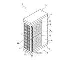
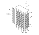
- FIG. 1 is a perspective view of the outdoor unit according to Embodiment 1 as viewed from the front side
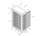
- FIG. 2 is a perspective view of the outdoor unit as viewed from the back side
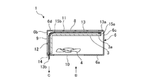
- 3 is a cross-sectional view taken along line AA in FIG.
- the outdoor unit 1 is arranged outside and constitutes an air conditioner that adjusts the indoor temperature or humidity together with an indoor unit (not shown) arranged indoors.
- the outdoor unit 1 includes a rectangular parallelepiped casing (main body) 2, a heat exchanger 3 accommodated in the casing 2, an outdoor fan 4, a compressor (not shown), and the like. ing.
- the casing 2 includes a top panel 5 that forms the upper surface of the outdoor unit 1, a main body panel 6 that forms a side surface portion of the outdoor unit 1, and a base 7 that forms the bottom surface of the outdoor unit 1.
- 1 is the front surface 6a of the main body panel 6, the left side surface of the main body panel 6 when viewed from the arrow B direction is the left side surface 6b, and the main body panel 6 when viewed from the arrow B direction.
- the right side surface is the right side surface 6c, and the surface facing the front surface 6a is the back surface 6d of the main body panel 6.
- the back surface 6d and the left side surface 6b of the main body panel 6 are formed with rectangular intake openings 8 and 9, and the front face 6a of the main body panel 6 is sucked into the casing 2 from the intake openings 8 and 9.
- An exhaust opening 10 for blowing out the outside air is formed.
- Protective nets 11 and 12 that cover the heat exchanger 3 are formed in the intake openings 8 and 9, respectively.
- the protective nets 11 and 12 have a lattice shape constituted by a plurality of vertical bars and horizontal bars and have a function of preventing an object from contacting the heat exchanger 3.
- the protective meshes 11 and 12 may be formed integrally with the back surface 6d and the left side surface 6b of the main body panel 6, or may be configured by fitting the protective mesh made of different members into the intake openings 8 and 9, respectively. Good.
- An outdoor fan 4 is disposed between the exhaust opening 10 and the heat exchanger 3.
- the outdoor fan 4 sucks outside air from the intake openings 8 and 9, passes the heat through the heat exchanger 3, and then discharges it from the exhaust opening 10.
- two outdoor fans 4 are stacked in the vertical direction of the casing 2, and two exhaust openings 10 corresponding to the two outdoor fans 4 are provided. Note that the number of outdoor fans 4 is not limited to two and can be changed as appropriate.
- the heat exchanger 3 has a plurality of thin fins and a copper pipe (not shown) through which the refrigerant flows and the outside air sucked from the intake openings 8 and 9 and the copper pipe Heat exchange with the refrigerant flowing through
- the heat exchanger 3 is disposed inside the casing 2 in the vicinity of the intake openings 8 and 9 in a standing state so as to close the intake openings 8 and 9, and a part of the heat exchanger 3 is disposed in the intake openings 8 and 9. It is exposed from the protective nets 11 and 12. Since the heat exchanger 3 blocks the intake openings 8 and 9, that is, the two surfaces (the left side surface 6b and the back surface 6d) of the main body panel 6, the AA line cross-sectional shape is L-shaped as shown in FIG. It arrange
- a protective member 13 covering the heat exchanger 3 exposed from between the protective meshes 11 and 12 provided in the intake openings 8 and 9 is provided between the back surface 6 d and the left side surface 6 b of the main body panel 6 and the heat exchanger 3.
- the protection member 13 is attached in the process of producing the outdoor unit 1 and is removed when the transportation and installation work is completed. This prevents the exposed heat exchanger 3 from being damaged in the process in which the outdoor unit 1 is transported and installed.
- FIG. 4 is a diagram illustrating a protection member of the outdoor unit according to Embodiment 1.
- the protective member 13 has folds that are continuous in the short direction, and a plurality of the folds are formed at fine intervals in the longitudinal direction. Thereby, the protection member 13 can be freely bent along the crease in the short direction.
- the protection member 13 is made of a soft material such as a corrugated board. As shown in FIG. 3, the end 13 a of the protection member 13 is inserted to the same position as the end 3 a of the heat exchanger 3, and the opposite end 13 b of the protection member 13 is provided on the front surface 6 a of the main body panel 6. It is arranged so as to protrude slightly from the slit hole 14.
- the slit hole 14 is formed in a region where the end portion 13 b of the protection member 13 is located when the protection member 13 is disposed in the casing 2 so as to close the intake openings 8 and 9.
- FIG. 3 shows a slit hole 14 formed in the region in parallel with the exhaust opening 10 with the vertical direction of the front surface 6a as the longitudinal direction of the opening.
- the opening of the slit hole 14 has a shape through which the short direction of the protective member 13 can pass.
- the first inner frame 15 a and the second inner frame 15 b are located between the heat exchanger 3 and the main body panel 6 and at two positions that do not hinder the heat exchange operation of the heat exchanger 3.
- the first inner frame 15a is erected at a position where the end 3a of the heat exchanger 3 abuts, and the bent portion of the L-shaped heat exchanger 3 abuts the second inner frame 15b.
- the first inner frame 15a has a function of guiding the arrangement of the end portion 13a of the inserted protection member 13
- the second inner frame 15b has the protection member 13 bent along the shape of the heat exchanger 3. And has a function of guiding the movement out of the casing 2 through the slit hole 14.
- the first inner frame 15a and the second inner frame 15b have curved surfaces (peripheral shapes) in contact with the protective member 13, so that the protective member 13 can be attached without damaging the heat exchanger 3.
- the protective member 13 can be pulled out from the slit hole 14 without damaging the heat exchanger 3.
- the end 13b of the protective member 13 protruding from the slit hole 14 is held and pulled out in the direction of arrow C.
- the protective member 13 moves in the direction of the slit hole 14 while changing its shape along the outer peripheral shape of the second inner frame 15b. Thereby, the whole protection member 13 can be smoothly pulled out from the slit hole 14 without damaging the heat exchanger 3.
- the heat exchanger 3, the outdoor unit fan 4, the compressor, and the like are installed. Further, the first inner frame 15a and the second inner frame 15b are erected at a predetermined position on the back surface 6d side of the heat exchanger 3.
- the protective member 13 is disposed so as to cover the heat exchanger 3 along the first inner frame 15a and the second inner frame 15b, and the slit 13 is formed with an end 13b on the front surface 6a of the main body panel 6. A predetermined amount protrudes from. Thereafter, the back surface 6d and the left side surface 6b of the main body panel 6 are assembled, and the top panel 5 is fitted.
- the assembling method is not limited to the one described above.
- the protective member 13 that can be freely bent in a predetermined direction is disposed between the heat exchanger 3 and the intake openings 8 and 9, and one end of the protective member 13 is slightly disposed. Since it is configured so as to protrude from the slit hole 14, the protective member can be arranged according to the shape of the heat exchanger, and further, by pulling out one end of the protruding protective member after the installation of the outdoor unit is completed. Can be easily removed.
- FIG. 1 In the first embodiment described above, the outdoor unit 1 having the heat exchanger 3 having an L-shaped cross section along the line AA is shown as an example.
- the cross-sectional shape along the line AA is a U shape. It shows about the case where a protection member is applied to the outdoor unit having the heat exchanger 3b.
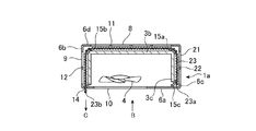
- FIG. 5 is a cross-sectional view of the outdoor unit according to the second embodiment, and a cross-sectional view of the outdoor unit according to the second embodiment is obtained at a portion corresponding to the line AA shown in FIG.
- the perspective view of the outdoor unit 1a according to the second embodiment viewed from the front surface 6a and the rear surface 6d is the same as that shown in FIG. 1 and FIG.
- the outdoor unit 1a is the same as the first embodiment in that the rectangular parallelepiped casing 2 includes the heat exchanger 3b, the outdoor fan 4, and the compressor in the casing 2.
- the main body panel 6 of the casing 2 includes the intake opening 21 having a rectangular shape on the right side surface 6c in addition to the back surface 6d and the left side surface 6b.
- a protective mesh 22 having a lattice shape composed of a plurality of vertical bars and horizontal bars is formed in the intake opening 21 of the right side surface 6c.
- the configuration of the protection network 22 is the same as that of the protection networks 11 and 12 shown in the first embodiment.
- the heat exchanger 3b includes the inside of the casing 2 in the vicinity of the intake openings 8, 9 and the intake opening 21 in a standing state so as to close the intake openings 8, 9 and the intake opening 21. A part thereof is exposed from the protection nets 11, 12, 22 of the intake openings 8, 9, 21. Since the heat exchanger 3b closes the intake openings 8, 9, and 21, that is, the three surfaces of the main body panel 6, as shown in FIG. 5, the horizontal cross-sectional shape is arranged in a U-shape. In addition, since the structure and function of heat exchanger 3b itself are the same as the heat exchanger 3 shown in Embodiment 1, description is abbreviate
- the protective member 23 has folds that are continuous in the short-side direction, like the protective member 13 of the first embodiment, and a plurality of the folds are formed at fine intervals in the longitudinal direction. Illustration is omitted. Thereby, the protection member 23 can be freely bent along the crease in the short direction.
- the protection member 23 is made of a soft material such as a corrugated board. As shown in FIG. 5, the end 23a of the protection member 23 is inserted to the same position as the end 3c of the heat exchanger 3b, and the opposite end 23b of the protection member 23 is provided on the front surface 6a of the main body panel 6. It is arranged so as to protrude slightly from the slit hole 14. Compared with the protective member 13 of the first embodiment, the length in the longitudinal direction of the protective member 23 is set longer than the intake opening 21 of the right side surface 6c.
- the slit hole 14 is an area where the end 23b of the protective member 23 is located when the protective member 23 is arranged in the casing 2 so as to close the intake openings 8, 9, and 21 as in the first embodiment. Formed.
- the opening of the slit hole 14 has a shape that allows the short direction of the protective member 23 to pass through.
- the first inner frame 15a, the second inner frame 15b, and the third inner frame 15c are arranged between the heat exchanger 3b and the main body panel 6 and in the heat exchange operation of the heat exchanger 3b. It is erected in a position that does not interfere.
- the first inner frame 15a and the second inner frame 15b are erected at a position where the bent portion of the U-shaped heat exchanger 3b contacts.
- the third inner frame 15c is erected at a position where the end 3c of the heat exchanger 3b contacts.
- the third inner frame 15c has a function of guiding the arrangement of the end portion 23a of the inserted protection member 23, and the first inner frame 15a and the second inner frame 15b have the protection member 23 as the heat exchanger 3b.
- the first inner frame 15a, the second inner frame 15b, and the third inner frame 15c have curved surfaces (peripheral shapes) in contact with the protective member 23 as shown in FIG.
- the protective member 23 can be disposed without being damaged, and the protective member 23 can be pulled out from the slit hole 14 without damaging the heat exchanger 3b.
- the assembling method of the outdoor unit 1a is the same as the method shown in the first embodiment.
- the rear surface 6d of the main body panel 6, the left side surface 6b, the right side surface 6c, and the heat exchanger 3b are disposed, bent, and moved by guiding the protection member 23 provided between them. Since the first inner frame 15a, the second inner frame 15b, the third inner frame 15c, and the slit hole 14 for pulling the protective member 23 out of the casing 2 are provided, the heat exchanger A protective member can be attached, and the protective member can be easily removed from the casing after the outdoor unit has been installed. Thereby, it is possible to easily prevent the heat exchanger from being damaged at the time of carrying or installing the outdoor unit.
- the protective member 23 that can be freely bent in a predetermined direction is disposed between the heat exchanger 3b and the intake openings 8, 9, and 21, and one end of the protective member 23 is disposed. Since it is configured so as to protrude from the slit hole 14, the protective member can be arranged according to the shape of the heat exchanger, and further, by pulling out one end of the protruding protective member after the installation of the outdoor unit is completed. Can be easily removed.
- the protection member 23 which protects the heat exchanger 3b arrange
- the heat exchanger is damaged.
- the entire protective member can be smoothly pulled out from the slit hole without any problem.
- Embodiment 3 FIG. In this Embodiment 3, when a outdoor unit is seen from the front surface 6a, the structure which can draw out a protection member from the right side surface 6c is shown.
- 6 is a perspective view of the outdoor unit according to Embodiment 3 as viewed from the front side
- FIG. 7 is a perspective view of the outdoor unit as viewed from the back side
- 8 is a cross-sectional view taken along line AA in FIG.
- the outdoor unit 1b is the same as the first embodiment in that the rectangular parallelepiped casing 2 includes the heat exchanger 3, the outdoor fan 4, and the compressor in the casing 2.
- the main body panel 6 of the casing 2 has rectangular intake openings 8 and 9 formed on the back surface 6d and the left side surface 6b, and an exhaust opening 10 formed on the front surface 6a of the main body panel 6. Protection nets 11 and 12 are formed in the intake openings 8 and 9. As shown in FIG. 8, the heat exchanger 3 is disposed so as to close the intake openings 8 and 9, that is, the AA line cross-sectional shape is L-shaped.
- the protective member 13 can be freely bent along a crease provided in the short direction as in the first embodiment, and is made of a soft material such as a corrugated board. As shown in FIG. 8, the end 13 b of the protection member 13 is inserted to the same position as the end 3 d of the heat exchanger 3, and the end 13 b of the protection member 13 is provided on the right side surface 6 c of the main body panel 6. It arrange
- the slit hole 31 is formed in a region where the end 13a of the protection member 13 is located when the protection member 13 is disposed in the casing 2 so as to close the intake openings 8 and 9.
- the slit hole 31 has a shape through which the short direction of the protection member 13 can pass.
- the second inner frame 15b (second guide member) and the fourth inner frame (first guide member) 15d are arranged between the heat exchanger 3 and the main body panel 6 and exchange heat as shown in FIG. It is erected at two positions that do not hinder the heat exchange operation of the vessel 3. More specifically, the second inner frame 15b is erected at a position where the bent portion of the L-shaped heat exchanger 3 comes into contact, and the end portion 3d of the heat exchanger 3 comes into contact with the fourth inner frame 15d. Standing at the position.
- the fourth inner frame 15 d has a function of guiding the arrangement of the inserted protection member 13, and the second inner frame 15 b is arranged so that the protection member 13 is removed from the heat exchanger 3 when the protection member 13 is pulled out from the slit hole 31.
- the protective member 13 can be disposed without damaging the heat exchanger 3, and the heat The protective member 13 can be pulled out from the slit hole 31 without damaging the exchanger 3.
- the end 13a of the protective member 13 protruding from the slit hole 31 is held and pulled out in the direction of arrow D.
- the protection member 13 moves toward the slit hole 31 while changing its shape along the outer peripheral shape of the second inner frame 15b. Thereby, the whole protection member 13 can be smoothly pulled out from the slit hole 31 without damaging the heat exchanger 3.
- the heat exchanger 3 is installed in a state where the base 7 of the casing 2 and the front surface 6a and the right side surface 6c of the main body panel 6 are assembled. Further, the second inner frame 15b and the fourth inner frame 15d are erected at predetermined positions on the back surface 6d side of the heat exchanger 3. Next, the protective member 13 is arranged so as to cover the heat exchanger 3 along the second inner frame 15b and the fourth inner frame 15d, and the slit 13 is formed with the end 13a on the right side surface 6c of the main body panel 6. A predetermined amount is projected from 31. Thereafter, the back surface 6d and the left side surface 6b of the main body panel 6 are assembled, and the top panel 5 is fitted.
- the assembling method is not limited to the one described above.
- the protective member 13 that can be freely bent in a predetermined direction is disposed between the heat exchanger 3 and the intake openings 8 and 9, and a little amount of one end of the protective member 13 is provided. Since it is configured so as to protrude from the slit hole 31, the protective member can be arranged according to the shape of the heat exchanger, and further, by pulling out one end of the protruding protective member after the installation of the outdoor unit is completed. Can be easily removed.
- the installation location is a place where the scaffolding in front of the outdoor unit cannot be secured, such as the outer wall of the second floor, or when the left side and the rear side are narrow spaces when the outdoor unit is viewed from the front,
- the protective member can be pulled out from the right side when viewed from the front.
- the entire protective member can be formed without damaging the heat exchanger. It can be pulled out smoothly from the slit hole.
- the first inner frame 15a, the second inner frame 15b, the third inner frame 15c, and the fourth inner frame 15d are limited to the shapes shown in the first to third embodiments. It is not a thing and it can change suitably. For example, any shape may be used as long as the protective member can be pulled out smoothly, such as standing a columnar rod. Further, the number of installed internal frames is not limited to the number shown in the first to third embodiments, and can be changed as appropriate.
- the outdoor unit according to the present invention has a configuration in which a simple protective member for preventing breakage of the heat exchanger can be easily arranged in the casing, and can be easily pulled out from the slit hole after installation. Therefore, it is suitable for protecting the heat exchanger of the outdoor unit installed in a small space.
Abstract
Description
実施の形態1.
図1から図3を参照しながら空気調和機の室外機(以下、室外機と称する)および室外機の保護部材の構成について説明する。なお、本実施の形態は、室外機に熱交換器の破損防止用に保護部材を設けるための構成を備えた点、および保護部材を設けた点に特徴があるため、その他の構成については説明を簡略化する。
図1は、実施の形態1に係る室外機を正面側から見た斜視図であり、図2は室外機を背面側から見た斜視図である。図3は、図1のA-A線断面図である。
この実施の形態1に係る室外機1は室外に配置され、室内に配置される室内機(不図示)と共に室内の温度または湿度を調整する空気調和機を構成する。室外機1は、図1から図3に示すように直方体形状のケーシング(本体)2、当該ケーシング2内部に収容される熱交換器3、室外ファン4、および圧縮機(不図示)などを備えている。
本体パネル6の背面6dおよび左側面6bには、矩形形状の吸気用開口部8,9が形成され、本体パネル6の正面6aには吸気用開口部8,9からケーシング2内に吸い込まれた外気を吹き出すための排気用開口部10が形成されている。
吸気用開口部8,9に設けた保護網11,12の間から露出する熱交換器3を覆う保護部材13が、本体パネル6の背面6dおよび左側面6bと熱交換器3との間に設けられる。当該保護部材13は、例えば室外機1が生産される過程で取り付けられ、運搬および据え付け作業が終了すると取り外される。これにより、室外機1が運搬および据え付けられる過程で、露出した熱交換器3が破損するのを防止する。
保護部材13は、短手方向に連続した折り目を有し、当該折り目は長手方向に細かい間隔で複数形成されている。これにより、保護部材13は短手方向の折り目に沿って自由に折り曲げ可能となる。保護部材13は、例えば段ボール板などの柔らかい素材で構成される。図3に示すように、保護部材13の端部13aは熱交換器3の端部3aと同様の位置まで挿入され、保護部材13の反対側端部13bは本体パネル6の正面6aに設けられたスリット孔14から若干量突出するように配置される。
スリット孔14は、吸気用開口部8,9を塞ぐように保護部材13をケーシング2内に配置した際に、当該保護部材13の端部13bが位置する領域に形成される。図3では、当該領域に排気用開口部10と並列して、正面6aの上下方向を開口の長手方向として形成したスリット孔14を示している。スリット孔14の開口部は、保護部材13の短手方向が通過可能な形状を有している。
まずケーシング2のベース7と本体パネル6の正面6aおよび右側面6cとを組み付けた状態で、熱交換器3、室外機ファン4および圧縮機などを設置する。さらに、熱交換器3の背面6d側の所定位置に第1の内部フレーム15aおよび第2の内部フレーム15bを立設させる。次に、保護部材13を第1の内部フレーム15aおよび第2の内部フレーム15bに沿って熱交換器3を覆うように配置し、端部13bを本体パネル6の正面6aに形成したスリット孔14から所定量突出させる。その後、本体パネル6の背面6dおよび左側面6bを組み付け、天面パネル5を勘合する。なお、組立方法は上述したものに限定されるものではない。
上述した実施の形態1ではA-A線断面形状がL字形状の熱交換器3を有する室外機1を例に示したが、この実施の形態2ではA-A線断面形状がU字形状の熱交換器3bを有する室外機に保護部材を適用する場合について示す。図5は実施の形態2に係る室外機の断面図であり、図1で示したA-A線に相当する部分で実施形態2に係る室外機の断面図を得たものである。
実施の形態2の室外機1aを正面6aおよび背面6dから見た斜視図は実施の形態1で示した図1および図2と同一であるため、記載を省略する。
また、室外機1aが直方体形状のケーシング2、当該ケーシング2内に熱交換器3b、室外ファン4および圧縮機などを備える点は実施の形態1と同様である。
スリット孔14は、実施の形態1と同様に吸気用開口部8,9,21を塞ぐように保護部材23をケーシング2内に配置した際に、当該保護部材23の端部23bが位置する領域に形成される。スリット孔14の開口部は、保護部材23の短手方向が通過可能な形状を有している。
なお、室外機1aの組立方法は、実施の形態1で示した方法と同様である。
この実施の形態3では、室外機を正面6aから見た場合に右側面6cから保護部材を引き抜き可能な構成を示す。
図6は、実施の形態3に係る室外機を正面側から見た斜視図であり、図7は室外機を背面側から見た斜視図である。図8は、図6のA-A線断面図である。
室外機1bが直方体形状のケーシング2、当該ケーシング2内に熱交換器3、室外ファン4および圧縮機などを備える点は実施の形態1と同様である。
まずケーシング2のベース7と本体パネル6の正面6aおよび右側面6cとを組み付けた状態で、熱交換器3、室外機ファン4および圧縮機などを設置する。さらに、熱交換器3の背面6d側の所定位置に第2の内部フレーム15bおよび第4の内部フレーム15dを立設させる。次に、保護部材13を第2の内部フレーム15bおよび第4の内部フレーム15dに沿って熱交換器3を覆うように配置し、端部13aを本体パネル6の右側面6cに形成したスリット孔31から所定量突出させる。その後、本体パネル6の背面6dおよび左側面6bを組み付け、天面パネル5を勘合する。なお、組立方法は上述したものに限定されるものではない。
また、据付場所が2階外壁など、室外機正面の足場が確保できない場所であった場合、あるいは室外機を正面から見た場合に左側および背面が狭小空間であった場合にも、室外機を正面から見て右側から保護部材を引き出すことができる。
Claims (7)
- 空気調和機の室外機において、
空気を吸気する開口部を有する本体と、
前記本体に収容され、前記開口部に表面を露出して配置される熱交換器と、
前記熱交換器と前記本体との間に配置されて前記開口部から露出した前記熱交換器の表面を覆う保護部材の配置および導出をガイドするガイド部材と、
前記保護部材を前記本体外に引き出すスリット孔とを備えたことを特徴とする室外機。 - 前記開口部は、前記本体の背面および一方の側面に形成され、
前記熱交換器は、前記本体の背面および一方の側面に形成された開口部から表面を露出するL字形状の水平断面形状を有し、
前記ガイド部材は、少なくとも、前記本体内へ挿入された前記保護部材の端部の配置をガイドする第1のガイド部材と、前記挿入された保護部材が前記熱交換器のL字形状に沿って屈曲するのをガイドすると共に前記L字形状に沿って前記本体外に移動するのをガイドする第2のガイド部材とで構成され、
前記スリット孔は、前記本体の正面に形成されることを特徴とする請求項1記載の室外機。 - 前記開口部は、前記本体の背面および両側面に形成され、
前記熱交換器は、前記本体の背面および両側面に形成された開口部から表面を露出するU字形状の水平断面形状を有し、
前記ガイド部材は、少なくとも、前記本体内に挿入された前記保護部材の端部の配置をガイドする第1のガイド部材と、前記挿入された保護部材が前記熱交換器のU字形状に沿って屈曲するのをガイドすると共に前記U字形状に沿って前記本体外に移動するのをガイドする第2および第3のガイド部材とで構成され、
前記スリット孔は、前記本体の正面に形成されることを特徴とする請求項1記載の室外機。 - 前記開口部は、前記本体の背面および一方の側面に形成され、
前記熱交換器は、前記本体の背面および一方の側面に形成された開口部から表面を露出するL字形状の水平断面形状を有し、
前記ガイド部材は、少なくとも、前記本体内に挿入された前記保護部材の端部の配置をガイドする第1のガイド部材と、前記挿入された保護部材が前記熱交換器のL字形状に沿って屈曲するのをガイドすると共に前記L字形状に沿って前記本体外に移動するのをガイドする第2のガイド部材とで構成され、
前記スリット孔は、前記本体の他方の側面に形成されることを特徴とする請求項1記載の室外機。 - 前記ガイド部材に沿って屈曲して前記熱交換器と前記本体との間に配置され、前記開口部から露出した前記熱交換器の表面を覆う保護部材を備えたことを特徴とする請求項1記載の室外機。
- 前記保護部材は、前記スリット孔を挿通可能な長さ且つ前記開口部から露出した前記熱交換器の表面を覆う面積を有し、前記本体内に挿入された状態で一方の端部が前記スリット孔から突出することを特徴とする請求項5記載の室外機。
- 空気調和機の室外機の組み立て方法において、
前記室外機の本体パネルに熱交換器およびガイド部材を取り付けるステップと、
前記ガイド部材に沿って、前記熱交換器を覆う保護部材を配置するステップと、
前記保護部材の端部を本体パネルに形成したスリット孔から所定量引き出すステップと、
前記保護部材を覆う本体パネルを取り付けるステップとを備えたことを特徴とする室外機の組立方法。
Priority Applications (5)
| Application Number | Priority Date | Filing Date | Title |
|---|---|---|---|
| JP2016522116A JP5968582B2 (ja) | 2014-05-27 | 2014-05-27 | 室外機および室外機の組立方法 |
| CN201480079294.XA CN106461244B (zh) | 2014-05-27 | 2014-05-27 | 室外机及室外机的组装方法 |
| US15/309,152 US20170082304A1 (en) | 2014-05-27 | 2014-05-27 | Outdoor unit and assembly method for outdoor unit |
| PCT/JP2014/063984 WO2015181892A1 (ja) | 2014-05-27 | 2014-05-27 | 室外機および室外機の組立方法 |
| EP14893588.5A EP3150930B1 (en) | 2014-05-27 | 2014-05-27 | Outdoor unit and assembly method for outdoor unit |
Applications Claiming Priority (1)
| Application Number | Priority Date | Filing Date | Title |
|---|---|---|---|
| PCT/JP2014/063984 WO2015181892A1 (ja) | 2014-05-27 | 2014-05-27 | 室外機および室外機の組立方法 |
Publications (1)
| Publication Number | Publication Date |
|---|---|
| WO2015181892A1 true WO2015181892A1 (ja) | 2015-12-03 |
Family
ID=54698276
Family Applications (1)
| Application Number | Title | Priority Date | Filing Date |
|---|---|---|---|
| PCT/JP2014/063984 WO2015181892A1 (ja) | 2014-05-27 | 2014-05-27 | 室外機および室外機の組立方法 |
Country Status (5)
| Country | Link |
|---|---|
| US (1) | US20170082304A1 (ja) |
| EP (1) | EP3150930B1 (ja) |
| JP (1) | JP5968582B2 (ja) |
| CN (1) | CN106461244B (ja) |
| WO (1) | WO2015181892A1 (ja) |
Cited By (1)
| Publication number | Priority date | Publication date | Assignee | Title |
|---|---|---|---|---|
| WO2020039471A1 (ja) * | 2018-08-20 | 2020-02-27 | 三菱電機株式会社 | 冷凍サイクル装置の室外機の梱包体 |
Citations (6)
| Publication number | Priority date | Publication date | Assignee | Title |
|---|---|---|---|---|
| JPS5690670U (ja) * | 1979-12-14 | 1981-07-20 | ||
| JPS626619U (ja) * | 1985-06-25 | 1987-01-16 | ||
| JPS63108036U (ja) * | 1986-12-29 | 1988-07-12 | ||
| JP2005114246A (ja) * | 2003-10-08 | 2005-04-28 | Hoshizaki Electric Co Ltd | 空気調和機の室外機 |
| JP2009030895A (ja) * | 2007-07-27 | 2009-02-12 | Sanyo Electric Co Ltd | 室外ユニット |
| JP2012242022A (ja) * | 2011-05-20 | 2012-12-10 | Daikin Industries Ltd | 冷凍装置の室外ユニット |
Family Cites Families (9)
| Publication number | Priority date | Publication date | Assignee | Title |
|---|---|---|---|---|
| US4261418A (en) * | 1979-12-12 | 1981-04-14 | Westinghouse Electric Corp. | Outdoor coil unit for heat pump |
| US4475585A (en) * | 1981-06-11 | 1984-10-09 | Snyder General Corporation | Air conditioning and heat pump cabinets with removable coil guards |
| US5971505A (en) * | 1998-08-26 | 1999-10-26 | Carrier Corporation | Snap-in grille for an air conditioner housing |
| KR100445467B1 (ko) * | 2001-04-20 | 2004-08-21 | 주식회사 엘지이아이 | 공기조화기의 실내기 |
| US6595017B1 (en) * | 2002-05-17 | 2003-07-22 | Matt Teahan | System for shading air conditioning units and method for installing the same |
| CN101539385B (zh) * | 2008-03-18 | 2011-07-13 | 珠海佳一电子技术有限公司 | 空气换热器芯片及其冲压模具和制造方法 |
| KR20100053903A (ko) * | 2008-11-13 | 2010-05-24 | 엘지전자 주식회사 | 공기 조화기 |
| US9352259B2 (en) * | 2010-10-08 | 2016-05-31 | Jing Lu | System, method and devices for air filtration |
| JP5771583B2 (ja) * | 2012-09-03 | 2015-09-02 | 日立アプライアンス株式会社 | 空気調和機の室外機 |
-
2014
- 2014-05-27 WO PCT/JP2014/063984 patent/WO2015181892A1/ja active Application Filing
- 2014-05-27 EP EP14893588.5A patent/EP3150930B1/en active Active
- 2014-05-27 CN CN201480079294.XA patent/CN106461244B/zh active Active
- 2014-05-27 US US15/309,152 patent/US20170082304A1/en not_active Abandoned
- 2014-05-27 JP JP2016522116A patent/JP5968582B2/ja not_active Expired - Fee Related
Patent Citations (6)
| Publication number | Priority date | Publication date | Assignee | Title |
|---|---|---|---|---|
| JPS5690670U (ja) * | 1979-12-14 | 1981-07-20 | ||
| JPS626619U (ja) * | 1985-06-25 | 1987-01-16 | ||
| JPS63108036U (ja) * | 1986-12-29 | 1988-07-12 | ||
| JP2005114246A (ja) * | 2003-10-08 | 2005-04-28 | Hoshizaki Electric Co Ltd | 空気調和機の室外機 |
| JP2009030895A (ja) * | 2007-07-27 | 2009-02-12 | Sanyo Electric Co Ltd | 室外ユニット |
| JP2012242022A (ja) * | 2011-05-20 | 2012-12-10 | Daikin Industries Ltd | 冷凍装置の室外ユニット |
Cited By (2)
| Publication number | Priority date | Publication date | Assignee | Title |
|---|---|---|---|---|
| WO2020039471A1 (ja) * | 2018-08-20 | 2020-02-27 | 三菱電機株式会社 | 冷凍サイクル装置の室外機の梱包体 |
| JPWO2020039471A1 (ja) * | 2018-08-20 | 2021-04-30 | 三菱電機株式会社 | 冷凍サイクル装置の室外機の梱包体 |
Also Published As
| Publication number | Publication date |
|---|---|
| JP5968582B2 (ja) | 2016-08-10 |
| US20170082304A1 (en) | 2017-03-23 |
| EP3150930B1 (en) | 2019-01-09 |
| CN106461244A (zh) | 2017-02-22 |
| EP3150930A1 (en) | 2017-04-05 |
| CN106461244B (zh) | 2017-11-28 |
| EP3150930A4 (en) | 2018-03-14 |
| JPWO2015181892A1 (ja) | 2017-04-20 |
Similar Documents
| Publication | Publication Date | Title |
|---|---|---|
| EP2792956B1 (en) | Outdoor unit of air conditioner | |
| EP2711641A1 (en) | Outdoor unit for refrigeration device | |
| EP2711640A1 (en) | Outdoor unit for refrigeration device | |
| US11421912B2 (en) | Packing system including packing material for air conditioner and air conditioner | |
| JP2014240727A (ja) | 室外ユニット | |
| JP5968582B2 (ja) | 室外機および室外機の組立方法 | |
| JP5402987B2 (ja) | 冷凍装置の室外ユニット | |
| KR20150031770A (ko) | 공기조화기 실외기의 컨트롤 박스 | |
| JP6591039B2 (ja) | 空気調和機の室外機 | |
| JP6281363B2 (ja) | 空気調和機の室外機 | |
| JP2014224663A (ja) | 熱交換換気装置 | |
| US11054154B2 (en) | Outdoor unit of refrigeration apparatus | |
| JP2017156038A (ja) | 防音カバー及びそれを備えた室外ユニット | |
| JP6004222B2 (ja) | ヒートシンク、及び、空気調和装置 | |
| JP6214504B2 (ja) | 熱交換換気装置 | |
| WO2019058461A1 (ja) | 空気調和機の室外ユニット | |
| JP6455074B2 (ja) | 熱交換器、空気調和機、及び熱交換器の製造方法 | |
| JP6352608B2 (ja) | 冷却装置、及び冷却装置付コントローラ | |
| JP6117500B2 (ja) | 情報処理機器室の空調システム、及び縮流軽減装置 | |
| JPWO2018025302A1 (ja) | 空気調和機の室内機 | |
| JP2017172929A (ja) | 冷凍サイクル装置の室外機、及び冷凍サイクル装置の室外機の製造方法 | |
| WO2020157850A1 (ja) | 空気調和機の室内機 | |
| WO2018173988A1 (ja) | 機械室カバーおよび冷蔵庫 | |
| JP5312433B2 (ja) | 空気調和機の室外機 | |
| JP5644378B2 (ja) | デッキパンの取付構造 |
Legal Events
| Date | Code | Title | Description |
|---|---|---|---|
| 121 | Ep: the epo has been informed by wipo that ep was designated in this application |
Ref document number: 14893588 Country of ref document: EP Kind code of ref document: A1 |
|
| ENP | Entry into the national phase |
Ref document number: 2016522116 Country of ref document: JP Kind code of ref document: A |
|
| WWE | Wipo information: entry into national phase |
Ref document number: 15309152 Country of ref document: US |
|
| NENP | Non-entry into the national phase |
Ref country code: DE |
|
| REEP | Request for entry into the european phase |
Ref document number: 2014893588 Country of ref document: EP |
|
| WWE | Wipo information: entry into national phase |
Ref document number: 2014893588 Country of ref document: EP |