WO2015163179A1 - Dispositif de frein - Google Patents
Dispositif de frein Download PDFInfo
- Publication number
- WO2015163179A1 WO2015163179A1 PCT/JP2015/061402 JP2015061402W WO2015163179A1 WO 2015163179 A1 WO2015163179 A1 WO 2015163179A1 JP 2015061402 W JP2015061402 W JP 2015061402W WO 2015163179 A1 WO2015163179 A1 WO 2015163179A1
- Authority
- WO
- WIPO (PCT)
- Prior art keywords
- parking brake
- brake
- parking
- mechanisms
- vehicle
- Prior art date
Links
Images


Classifications
-
- B—PERFORMING OPERATIONS; TRANSPORTING
- B60—VEHICLES IN GENERAL
- B60T—VEHICLE BRAKE CONTROL SYSTEMS OR PARTS THEREOF; BRAKE CONTROL SYSTEMS OR PARTS THEREOF, IN GENERAL; ARRANGEMENT OF BRAKING ELEMENTS ON VEHICLES IN GENERAL; PORTABLE DEVICES FOR PREVENTING UNWANTED MOVEMENT OF VEHICLES; VEHICLE MODIFICATIONS TO FACILITATE COOLING OF BRAKES
- B60T7/00—Brake-action initiating means
- B60T7/02—Brake-action initiating means for personal initiation
- B60T7/08—Brake-action initiating means for personal initiation hand actuated
- B60T7/10—Disposition of hand control
- B60T7/107—Disposition of hand control with electrical power assistance
-
- F—MECHANICAL ENGINEERING; LIGHTING; HEATING; WEAPONS; BLASTING
- F16—ENGINEERING ELEMENTS AND UNITS; GENERAL MEASURES FOR PRODUCING AND MAINTAINING EFFECTIVE FUNCTIONING OF MACHINES OR INSTALLATIONS; THERMAL INSULATION IN GENERAL
- F16D—COUPLINGS FOR TRANSMITTING ROTATION; CLUTCHES; BRAKES
- F16D65/00—Parts or details
- F16D65/14—Actuating mechanisms for brakes; Means for initiating operation at a predetermined position
- F16D65/16—Actuating mechanisms for brakes; Means for initiating operation at a predetermined position arranged in or on the brake
- F16D65/18—Actuating mechanisms for brakes; Means for initiating operation at a predetermined position arranged in or on the brake adapted for drawing members together, e.g. for disc brakes
-
- B—PERFORMING OPERATIONS; TRANSPORTING
- B60—VEHICLES IN GENERAL
- B60T—VEHICLE BRAKE CONTROL SYSTEMS OR PARTS THEREOF; BRAKE CONTROL SYSTEMS OR PARTS THEREOF, IN GENERAL; ARRANGEMENT OF BRAKING ELEMENTS ON VEHICLES IN GENERAL; PORTABLE DEVICES FOR PREVENTING UNWANTED MOVEMENT OF VEHICLES; VEHICLE MODIFICATIONS TO FACILITATE COOLING OF BRAKES
- B60T13/00—Transmitting braking action from initiating means to ultimate brake actuator with power assistance or drive; Brake systems incorporating such transmitting means, e.g. air-pressure brake systems
- B60T13/74—Transmitting braking action from initiating means to ultimate brake actuator with power assistance or drive; Brake systems incorporating such transmitting means, e.g. air-pressure brake systems with electrical assistance or drive
- B60T13/741—Transmitting braking action from initiating means to ultimate brake actuator with power assistance or drive; Brake systems incorporating such transmitting means, e.g. air-pressure brake systems with electrical assistance or drive acting on an ultimate actuator
-
- B—PERFORMING OPERATIONS; TRANSPORTING
- B60—VEHICLES IN GENERAL
- B60T—VEHICLE BRAKE CONTROL SYSTEMS OR PARTS THEREOF; BRAKE CONTROL SYSTEMS OR PARTS THEREOF, IN GENERAL; ARRANGEMENT OF BRAKING ELEMENTS ON VEHICLES IN GENERAL; PORTABLE DEVICES FOR PREVENTING UNWANTED MOVEMENT OF VEHICLES; VEHICLE MODIFICATIONS TO FACILITATE COOLING OF BRAKES
- B60T13/00—Transmitting braking action from initiating means to ultimate brake actuator with power assistance or drive; Brake systems incorporating such transmitting means, e.g. air-pressure brake systems
- B60T13/74—Transmitting braking action from initiating means to ultimate brake actuator with power assistance or drive; Brake systems incorporating such transmitting means, e.g. air-pressure brake systems with electrical assistance or drive
- B60T13/746—Transmitting braking action from initiating means to ultimate brake actuator with power assistance or drive; Brake systems incorporating such transmitting means, e.g. air-pressure brake systems with electrical assistance or drive and mechanical transmission of the braking action
-
- B—PERFORMING OPERATIONS; TRANSPORTING
- B60—VEHICLES IN GENERAL
- B60T—VEHICLE BRAKE CONTROL SYSTEMS OR PARTS THEREOF; BRAKE CONTROL SYSTEMS OR PARTS THEREOF, IN GENERAL; ARRANGEMENT OF BRAKING ELEMENTS ON VEHICLES IN GENERAL; PORTABLE DEVICES FOR PREVENTING UNWANTED MOVEMENT OF VEHICLES; VEHICLE MODIFICATIONS TO FACILITATE COOLING OF BRAKES
- B60T8/00—Arrangements for adjusting wheel-braking force to meet varying vehicular or ground-surface conditions, e.g. limiting or varying distribution of braking force
- B60T8/17—Using electrical or electronic regulation means to control braking
-
- F—MECHANICAL ENGINEERING; LIGHTING; HEATING; WEAPONS; BLASTING
- F16—ENGINEERING ELEMENTS AND UNITS; GENERAL MEASURES FOR PRODUCING AND MAINTAINING EFFECTIVE FUNCTIONING OF MACHINES OR INSTALLATIONS; THERMAL INSULATION IN GENERAL
- F16D—COUPLINGS FOR TRANSMITTING ROTATION; CLUTCHES; BRAKES
- F16D65/00—Parts or details
- F16D65/14—Actuating mechanisms for brakes; Means for initiating operation at a predetermined position
- F16D65/16—Actuating mechanisms for brakes; Means for initiating operation at a predetermined position arranged in or on the brake
- F16D65/18—Actuating mechanisms for brakes; Means for initiating operation at a predetermined position arranged in or on the brake adapted for drawing members together, e.g. for disc brakes
- F16D65/183—Actuating mechanisms for brakes; Means for initiating operation at a predetermined position arranged in or on the brake adapted for drawing members together, e.g. for disc brakes with force-transmitting members arranged side by side acting on a spot type force-applying member
-
- B—PERFORMING OPERATIONS; TRANSPORTING
- B60—VEHICLES IN GENERAL
- B60T—VEHICLE BRAKE CONTROL SYSTEMS OR PARTS THEREOF; BRAKE CONTROL SYSTEMS OR PARTS THEREOF, IN GENERAL; ARRANGEMENT OF BRAKING ELEMENTS ON VEHICLES IN GENERAL; PORTABLE DEVICES FOR PREVENTING UNWANTED MOVEMENT OF VEHICLES; VEHICLE MODIFICATIONS TO FACILITATE COOLING OF BRAKES
- B60T1/00—Arrangements of braking elements, i.e. of those parts where braking effect occurs specially for vehicles
- B60T1/005—Arrangements of braking elements, i.e. of those parts where braking effect occurs specially for vehicles by locking of wheel or transmission rotation
-
- F—MECHANICAL ENGINEERING; LIGHTING; HEATING; WEAPONS; BLASTING
- F16—ENGINEERING ELEMENTS AND UNITS; GENERAL MEASURES FOR PRODUCING AND MAINTAINING EFFECTIVE FUNCTIONING OF MACHINES OR INSTALLATIONS; THERMAL INSULATION IN GENERAL
- F16D—COUPLINGS FOR TRANSMITTING ROTATION; CLUTCHES; BRAKES
- F16D2121/00—Type of actuator operation force
- F16D2121/18—Electric or magnetic
- F16D2121/24—Electric or magnetic using motors
-
- F—MECHANICAL ENGINEERING; LIGHTING; HEATING; WEAPONS; BLASTING
- F16—ENGINEERING ELEMENTS AND UNITS; GENERAL MEASURES FOR PRODUCING AND MAINTAINING EFFECTIVE FUNCTIONING OF MACHINES OR INSTALLATIONS; THERMAL INSULATION IN GENERAL
- F16D—COUPLINGS FOR TRANSMITTING ROTATION; CLUTCHES; BRAKES
- F16D2125/00—Components of actuators
- F16D2125/18—Mechanical mechanisms
- F16D2125/20—Mechanical mechanisms converting rotation to linear movement or vice versa
- F16D2125/34—Mechanical mechanisms converting rotation to linear movement or vice versa acting in the direction of the axis of rotation
- F16D2125/42—Rack-and-worm gears
-
- F—MECHANICAL ENGINEERING; LIGHTING; HEATING; WEAPONS; BLASTING
- F16—ENGINEERING ELEMENTS AND UNITS; GENERAL MEASURES FOR PRODUCING AND MAINTAINING EFFECTIVE FUNCTIONING OF MACHINES OR INSTALLATIONS; THERMAL INSULATION IN GENERAL
- F16D—COUPLINGS FOR TRANSMITTING ROTATION; CLUTCHES; BRAKES
- F16D2125/00—Components of actuators
- F16D2125/18—Mechanical mechanisms
- F16D2125/58—Mechanical mechanisms transmitting linear movement
- F16D2125/60—Cables or chains, e.g. Bowden cables
-
- F—MECHANICAL ENGINEERING; LIGHTING; HEATING; WEAPONS; BLASTING
- F16—ENGINEERING ELEMENTS AND UNITS; GENERAL MEASURES FOR PRODUCING AND MAINTAINING EFFECTIVE FUNCTIONING OF MACHINES OR INSTALLATIONS; THERMAL INSULATION IN GENERAL
- F16D—COUPLINGS FOR TRANSMITTING ROTATION; CLUTCHES; BRAKES
- F16D63/00—Brakes not otherwise provided for; Brakes combining more than one of the types of groups F16D49/00 - F16D61/00
- F16D63/006—Positive locking brakes
Definitions
- This invention relates to a brake device having a left and right independent mechanism, and relates to a technique for reducing operating noise when a parking brake is operated.
- Brake devices have been proposed that can generate a braking force using an electric motor as a drive source and maintain the braking force even after energization of the electric motor is stopped.
- this brake device not a little operation noise is generated when the parking brake is operated, and there is a sense of incongruity or discomfort due to this operation sound.
- Specific examples of the operating sound include, for example, a sound emitted from a ratchet attached to the press generation mechanism, a sound at the time of fastening the lock mechanism, and a sound at the time of pressure increase that generates a braking force. There was a need to reduce discomfort.
- Patent Document 3 there is a method of giving a sense of security by impressing that this is a normal phenomenon caused by the operation of the parking brake, and making the operation sound itself difficult to notice with an electronic sound.
- Patent Document 1 that optimizes the configuration and arrangement of the motor and the reduction gear
- the configuration and arrangement of the motor and the reduction gear are limited, and the versatility of the electric brake device with a parking brake is lowered.
- Patent Document 2 in which the lock mechanism is provided with an elastic portion, the structure of the apparatus becomes complicated and the manufacturing cost increases.
- the operation noise cannot be suppressed.
- Patent Document 3 that generates the electronic sound, for example, depending on the size or frequency band of the electronic sound, the operating sound when the parking brake is operated may not be appropriately suppressed. It may be the cause of operating noise. Due to these operating sounds, the driver or the like is uncomfortable or uncomfortable.
- An object of the present invention is to provide a brake device that can improve the versatility of the device and can reduce discomfort and discomfort caused by the operating sound of a parking brake.
- the brake device applies left and right parking brake mechanisms 1L and 1R that independently apply braking force to the left and right wheels of the vehicle and maintains the vehicle in a stopped state, and these parking brake mechanisms 1L. , 1R, and a braking device including a control device 2 for controlling 1R,
- the control device 2 is provided with a parking brake operation determination device 12 for adjusting the mutual timing for operating the left and right parking brake mechanisms 1L and 1R so as to reduce the uncomfortable feeling given to the vehicle occupant.
- the operation timing can also be determined independently. Therefore, focusing on the operation sound (hereinafter simply referred to as “operation sound”) that is most likely to cause discomfort and discomfort among the operation sounds when the parking brake is operated, for example, the generation timing of the operation command is By controlling, it is possible to manage the generation timing of the operation sound, and to reduce discomfort and discomfort given to the driver or the like even if the same operation sound is generated. Therefore, the uncomfortable feeling and discomfort caused by the operating sound of the parking brake can be reduced.
- operation sound hereinafter simply referred to as “operation sound”
- the generation timing of the operation command is By controlling, it is possible to manage the generation timing of the operation sound, and to reduce discomfort and discomfort given to the driver or the like even if the same operation sound is generated. Therefore, the uncomfortable feeling and discomfort caused by the operating sound of the parking brake can be reduced.
- the control device 2 when the driver operates, for example, the parking brake request switch 13 or the like, the control device 2 switches the left and right parking brake mechanisms 1L and 1R from the unlocked state to the parking locked state, respectively.
- the parking brake operation determination unit 12 in the control device 2 adjusts the timing for operating the left and right parking brake mechanisms 1L and 1R. For example, by performing processing such as rewriting the control flow of the control device 2, it is possible to reduce discomfort and discomfort due to the operating sound, and therefore, the configuration and arrangement of the components are limited as in the prior art. There is nothing. For this reason, the versatility of a brake device can be improved.
- the generation timing of the operating sound that reduces discomfort and discomfort depends on the sound pressure level and frequency distribution of the operating sound, the arrangement and mounting method of the parking brake mechanisms 1L and 1R, the propagation path and resonance of the operating sound to the vehicle, and the state of chatter. It is set in advance when designing the vehicle.
- the sound pressure level of the operating sound is low, the sound pressure level can be kept low even if the left and right parking brake mechanisms 1L and 1R are operated simultaneously on the left and right sides, and the generation time of the operating sound is shortened. And discomfort can be reduced.
- the vehicle configuration can be expected to have a shielding effect for operating noise and a damping effect for vibration that is the source of the operating noise, the sound pressure level that can be heard by the vehicle occupant is reduced even if the amplitude of the operating noise and vibration increases. Since it can be suppressed, the left and right parking brake mechanisms 1L and 1R can be operated simultaneously on the left and right sides to shorten the operating noise and the generation time of vibration, and to reduce discomfort and discomfort, as in the above example.
- the generation time of the operation sound is the time that the operation sound is heard by the occupant.
- the generation time is one time of the normal operation.
- the generation time is twice as long as the normal operation.
- the left and right parking brake mechanisms 1L and 1R are sequentially operated at different timings to keep the sound pressure level peak low. Can reduce discomfort and discomfort.
- the sound insulation effect of the operation sound or the vibration suppression effect that causes the operation sound cannot be expected due to the vehicle configuration, specifically, the air easily propagates or resonance or chatter noise (beat noise) occurs.
- the left and right parking brake mechanisms 1L and 1R are sequentially operated in order to keep the operating sound and vibration amplitude small, thereby suppressing the peak of the sound pressure level and reducing discomfort and discomfort. Can do.
- the operating sound is in a frequency band where the passenger is not likely to feel discomfort or discomfort even if the sound pressure level is high, it is desirable to operate the left and right parking brake mechanisms 1L and 1R simultaneously. If the sound pressure level is very low and cannot be perceived if the parking brake mechanism 1L, (1R) on one side is operated, the operation sound can be perceived if the parking brake mechanisms 1L, 1R on both the left and right sides are operated. It is desirable to adopt a method of continuously operating the parking brake mechanisms 1L, 1R. As described above, in practice, it is appropriate to change the generation timing of the operation command to the parking brake mechanisms 1L and 1R at the time of vehicle design and perform a sensory survey to adopt the timing with the least discomfort and discomfort.
- the parking brake operation determination unit 12 reduces the uncomfortable feeling given to the occupant of the vehicle based on the set timing. , 1R, a parking brake operation command may be input to operate the vehicle in a parking lock state for maintaining the vehicle in a stopped state.
- the timing with the least discomfort and discomfort is set according to the results of tests, simulations, and the like.
- the parking brake operation determining device 12 is A parking brake operation command is input to one of the left and right parking brake mechanisms 1L, 1R to complete the operation of the one parking brake mechanism 1L, (1R).
- An operation completion signal monitoring means 16 for monitoring the presence or absence of an operation completion signal indicating that, When there is an operation completion signal by the operation completion signal monitoring means 16, an operation command for inputting a parking brake operation command to the other parking brake mechanism 1R, (1L) in the left and right parking brake mechanisms 1L, 1R. It is good also as what has the input means 17 sequentially.
- the parking brake operation determination device 12 inputs a parking brake operation command to one parking brake mechanism 1L, (1R)
- the operation completion signal monitoring means 16 stands by until receiving an operation completion signal.
- the operation command sequential input means 17 inputs a parking brake operation command to the other parking brake mechanism 1R, (1L).
- the parking brake operation determination unit 12 may operate the left and right parking brake mechanisms 1L and 1R simultaneously as the timing. For example, when the sound pressure level of the operating sound is low, or when the effect of shielding the operating sound or the vibration suppression effect of the operating sound can be expected depending on the vehicle configuration, the left and right parking brake mechanisms 1L and 1R are installed. By operating simultaneously, the generation time of an operation sound and a vibration can be shortened, and the discomfort and discomfort of the vehicle occupant can be reduced.
- the parking brake operation determining device 12 is Setting time observation means for determining whether a set time has elapsed by inputting a parking brake operation command to one of the left and right parking brake mechanisms 1L, 1R. 14 and When it is determined by the set time observation means 14 that the set time has elapsed, a parking brake operation command is input to the other parking brake mechanism 1R, (1L) of the left and right parking brake mechanisms 1L, 1R. It is good also as what has the operation command waiting means 15 to perform.
- the set time is determined by sensory evaluation or the like at the time of vehicle design, for example.
- the parking brake operation determination device 12 inputs a parking brake operation command to one parking brake mechanism 1L, (1R)
- the set time observation means 14 determines whether or not the set time has elapsed. judge.
- the operation command waiting unit 15 inputs a parking brake operation command to the other parking brake mechanism 1R, (1L).
- the parking brake operation determination unit 12 has a timing for operating the left and right parking brake mechanisms 1L and 1R and a timing for operating a set mechanism that generates a working sound in the vehicle. It is good also as what adjusts so that the discomfort given to the passenger
- An example of the set mechanism is a door lock mechanism.
- the vehicle door lock mechanism is When the operation sound is generated, the parking brake mechanism is operated in consideration of the operation sound of the door lock mechanism.
- the parking brake mechanism is operated while the occupant is in the vehicle, it is more convenient for the occupant to release the door lock mechanism. Therefore, when the door lock mechanism is also released when the parking brake is operated, an operation sound is generated even when the door lock mechanism is released. Therefore, the timing for operating the door lock mechanism and the parking brake mechanisms 1L and 1R are operated. By adjusting the timing (for example, operating the parking brake almost simultaneously when the door lock mechanism is operated), it is possible to reduce discomfort and discomfort due to the parking brake operation.
- the left and right electric brake mechanisms can be independently applied to the left and right wheels 5 and 5 in the vehicle and are operated by the brake operation means 104 by the driver.
- the left and right parking brake mechanisms 102L and 102R are independent of left and right in a parking lock state that prevents the braking force of the left and right electric brake mechanisms 101L and 101R from loosening and an unlocked state that allows the braking force to loosen.
- the control device 103 controls the electric brake mechanisms 101L and 101R and the parking brake mechanisms 102L and 102R,
- the parking brake operation determining unit 119 determines the mutual timing of the operation of the left and right parking brake mechanisms 102L and 102R that operate the parking brake mechanisms 102L and 102R from the unlocked state to the parking locked state, respectively. Adjust to reduce the discomfort given to the passengers.
- the Applicant has applied control measures such as optimizing the generation timing of the operation command. It has been found that there is room for reduction in discomfort and discomfort.
- the operation timing of the left and right parking brake mechanisms can be determined independently. Therefore, paying attention to the “operation sound” that is most likely to cause discomfort and discomfort among the operation sounds during parking brake operation, for example, by controlling the generation timing of the operation command, the generation timing of the operation sound Can be controlled to reduce discomfort and discomfort to the driver even if the same operating noise is generated. Therefore, the uncomfortable feeling and discomfort caused by the operating sound of the parking brake can be reduced.
- the control device 103 when the driver operates the brake operation means 104 in a normal time when performing a so-called service brake operation, the control device 103 causes the left and right electric brake mechanisms 101L and 101R to be respectively applied to the left and right wheels 5 and 5.
- the left and right electric brake mechanisms 101L and 101R are controlled so that the braking force is applied independently.
- the driver When operating the parking brake mechanisms 102L and 102R, the driver operates the parking brake request switch 21 and the like, for example, when the vehicle is stopped using the electric brake mechanisms 101L and 101R and the like. Then, control device 103 switches left and right parking brake mechanisms 102L and 102R from the unlocked state to the parking locked state.
- the parking brake operation determination unit 119 in the control device 103 adjusts the operation timing of the left and right parking brake mechanisms 102L and 102R that operate the parking brake mechanisms 102L and 102R from the unlocked state to the parking locked state, respectively.
- the parking brake operation determination unit 119 in the control device 103 adjusts the operation timing of the left and right parking brake mechanisms 102L and 102R that operate the parking brake mechanisms 102L and 102R from the unlocked state to the parking locked state, respectively.
- processing such as rewriting the control flow of the control device 103, it is possible to reduce discomfort and discomfort caused by the operating sound, so that the configuration and arrangement of the electric motor and the speed reduction mechanism are the same as in the prior art. There is no limit. For this reason, the versatility of the electric brake device can be improved.
- the generation timing of the operating sound that reduces discomfort and discomfort depends on the sound pressure level and frequency distribution of the operating sound, the arrangement and mounting method of the parking brake mechanisms 102L and 102R, the propagation path and resonance of the operating sound to the vehicle, and the degree of chatter. It is set in advance when designing the vehicle.
- the sound pressure level of the operating sound is low, the sound pressure level can be kept low even if the left and right parking brake mechanisms 102L and 102R are operated simultaneously on the left and right sides, and the operation sound generation time is shortened. And discomfort can be reduced.
- the vehicle configuration can be expected to have a shielding effect for operating noise and a damping effect for vibration that is the source of the operating noise, the sound pressure level that can be heard by the vehicle occupant is reduced even if the amplitude of the operating noise and vibration increases. Since it can be suppressed, the left and right parking brake mechanisms 102L and 102R can be operated at the same time on the left and right sides to shorten the generation time of the operating sound and vibration, and to reduce discomfort and discomfort, as in the above example.
- the generation time of the operation sound is the time that the operation sound is heard by the occupant.
- the generation time is one time of the normal operation.
- the generation time is twice as long as the normal operation.
- the left and right parking brake mechanisms 102L and 102R are sequentially operated at different timings to keep the sound pressure level peak low. Can reduce discomfort and discomfort.
- the sound insulation effect of the operation sound or the vibration suppression effect that causes the operation sound cannot be expected due to the vehicle configuration, specifically, the air easily propagates or resonance or chatter noise (beat noise) occurs.
- the left and right parking brake mechanisms 102L and 102R are sequentially operated in order to keep the sound and vibration amplitude small, thereby suppressing the peak of the sound pressure level and reducing discomfort and discomfort. Can do.
- the operating sound is in a frequency band where it is difficult for the occupant to feel uncomfortable or uncomfortable even if the sound pressure level is high, it is desirable to operate the left and right parking brake mechanisms 102L and 102R simultaneously. If the sound pressure level is very low and it cannot be perceived if the parking brake mechanism 102L, (102R) on one side is operated, the operation sound can be perceived if the parking brake mechanisms 102L, 102R on both the left and right sides are operated. It is desirable to employ a method of continuously operating the parking brake mechanisms 102L and 102R of the vehicle. In this way, in practice, it is appropriate to change the generation timing of the operation command to the parking brake mechanisms 102L and 102R at the time of vehicle design and perform a sensory survey to adopt the timing with the least sense of discomfort and discomfort.
- the electric brake mechanisms 101L and 101R include an electric motor 106, a brake rotor 109, a friction pad 110 that comes into contact with the brake rotor 109 to generate a braking force, and a speed reduction mechanism 107 that reduces the rotation of the electric motor 106.
- a linear motion mechanism 108 that converts the rotational motion output by the speed reduction mechanism 107 into the linear motion of the friction pad 110, and
- the parking brake mechanisms 102L and 102R are A lock member 116 to be engaged with an engagement hole 118 provided in the speed reduction mechanism 107; The parking lock state in which the lock member 116 is locked in the locking hole 118 and the rotational movement of the speed reduction mechanism 107 is restricted, and the unlocked state in which the lock member 116 is released from the locking hole 118.
- An actuator 117 that performs switching drive may be provided.
- the parking brake operation determining unit 119 is caused by the operating noise by adjusting the operation timing of the parking brake mechanisms 102L and 102R according to the cause of the operating noise. It is possible to reduce discomfort and discomfort.
- the left and right electric brake mechanisms 101L and 101R are respectively output brake press commands to generate left and right set pressures.
- the brake press generators 120L and 120R may be provided in the control device 103.
- the set pressing force is determined from the braking force necessary for stopping the vehicle, for example, as a result of a test or simulation. According to this configuration, the right and left parking brake mechanisms 102L and 102R can be operated after the left and right brake press generators 120L and 120R respectively output brake press commands to generate the set pressing force.
- the parking brake operation determination unit 119 may generate the brake press request signal based on the set timing to the left and right brake press generators 120L and 120R. good.
- the parking brake operation determining unit 119 in response to a parking brake operation request from the parking brake request switch 121 or the like, the parking brake operation determining unit 119 generates a brake pressing request signal in one of the left and right brake pressing generators 120L and 120R, for example. To do. Thereafter, the parking brake operation determination unit 119 generates a brake press request signal to the other brake press generator 120R (120L) based on the set timing. The parking brake operation determination unit 119 may generate a brake press request signal simultaneously to the left and right brake press generators 120L and 120R.
- the parking brake operation determination unit 119 monitors the feedback values of the pressing forces generated by the electric brake mechanisms 101L and 101R after outputting the left and right brake pressing request signals, and those pressing forces exceed a threshold value.
- the parking brake operation command may be generated for the left and right parking brake mechanisms 102L and 102R based on the set timing to activate the parking lock state.
- the threshold is determined, for example, by a result of experiment or simulation.
- the parking brake operation determination unit 119 monitors the feedback value of the pressing force generated by each of the electric brake mechanisms 101L and 101R after outputting the left and right brake pressing request signals.
- the feedback value of the pressing force of any of the electric brake mechanisms 101L and 101R is equal to or less than the threshold value, for example, the process of monitoring the feedback value of the pressing force of the electric brake mechanisms 101L and 101R is repeated.
- the parking brake operation determination unit 119 generates a parking brake operation command for each of the parking brake mechanisms 102L and 102R based on the set timing. Therefore, it is possible to reduce discomfort and discomfort caused by the operating sound, and it is possible to reliably stop the vehicle.
- the parking brake operation determination unit 119 generates a parking brake operation command to the left and right parking brake mechanisms 102L and 102R according to a predetermined condition after outputting the left and right brake pressing request signals, and generates the parking lock. Is to act on the state, The parking brake operation determination unit 119 may output the left and right brake pressing request signals and the left and right parking brake operation commands based on the set timing.
- 1 is a block diagram showing a schematic configuration of a main part of a vehicle equipped with a brake device according to a first embodiment of the present invention in plan view. It is a block diagram of the control system of the brake device. 5 is a flowchart showing an example of shifting the time for operating the left and right parking brake mechanisms in the brake device. 3 is a flowchart showing an example using a parking brake operation completion signal in the brake device. It is a block diagram which shows schematic structure of the principal part of the vehicle carrying the brake device which concerns on 2nd Embodiment by planar view. It is a figure which shows schematically the brake device which concerns on 3rd Embodiment of this invention.
- the brake device includes left and right parking brake mechanisms 1L and 1R, and a control device 2 that controls the parking brake mechanisms 1L and 1R.
- the left and right parking brake mechanisms 1L and 1R for example, a structure in which the wires 3 and 3 of a so-called wire type parking brake are pulled by drive sources 4 and 4 such as electric motors and actuators prepared separately for the left and right are applied.
- the left and right parking brake mechanisms 1L and 1R are not limited to this structure.
- a vehicle equipped with this brake device is provided with, for example, a hydraulic or electric brake device as a service brake 6 for braking the front, rear, left and right wheels 5.
- left and right parking brake mechanisms 1L, 1R are provided for the left and right wheels 5, 5 on the rear wheel side.
- the left and right parking brake mechanisms 1L and 1R may be provided for the left and right wheels 5 and 5 on the front wheel side, or the left and right parking brake mechanisms 1L and 1R may be provided for the front and rear left and right wheels 5 and 5. good.
- the parking brake mechanisms 1L and 1R independently apply braking force to the left and right wheels 5 and 5 of the vehicle, respectively, and maintain the vehicle in a stopped state.
- the parking brake mechanisms 1L and 1R apply a braking force by using, for example, a friction pad (not shown) and a brake rotor (not shown) of the service brake 6.
- the parking brake mechanisms 1L and 1R each have a drive source 4, a worm gear mechanism 7, a wire 3, and a brake shoe lever or push rod / cam mechanism (not shown).
- a drum brake is applied as the service brake 6, the brake shoe lever is applied.
- a disc brake is applied as the service brake 6, the push rod / cam mechanism is applied.
- the push rod / cam mechanism is a cam (not shown) connected to the wire 3, a push rod (not shown) pressed by the pressing force of the cam, and a pressing force from the push rod is increased and transmitted to the friction pad.
- a piston (not shown).
- the worm gear mechanism 7 has a worm 8 on the driving side, a worm wheel 9 on the driven side, and a take-up reel 10 as shown by being surrounded by a one-dot chain line.
- the worm 8 is connected to a motor shaft (not shown) of the electric motor that is the drive source 4.
- the worm wheel 9 is engaged with the worm 8, and the take-up reel 10 is rotated by the rotation of the worm wheel 9.
- the wire 3 is taken up by the rotation of the take-up reel 10.
- the wire 3 is wound up via the worm 8, the worm wheel 9, and the take-up reel 10.
- the worm wheel 9 is provided with a ratchet mechanism 11 that prevents reverse rotation even when the electric motor stops driving or is not energized.
- a ratchet mechanism 11 that prevents reverse rotation even when the electric motor stops driving or is not energized.
- the ratchet mechanism 11 keeps the braking force from being loosened even after the main power of the vehicle is turned off. That is, the vehicle is kept stopped.
- FIG. 2 is a block diagram of the control system of this brake device.
- the brake device control device 2 includes a parking brake operation determination unit 12.
- the control device 2 includes a computer having a processor, a ROM (Read Only Memory) having a program executed by the processor, and other electronic circuits such as a RAM (Random Access Memory) and a coprocessor (Co-Processor).
- the parking brake operation determination unit 12 adjusts the left and right parking brake mechanisms 1L and 1R so as to reduce the uncomfortable feeling and discomfort that are given to the vehicle occupant when the left and right parking brake mechanisms 1L and 1R are operated from the unlocked state to the parking locked state, respectively.
- the parking brake operation determination unit 12 When the driver wants to operate the parking brake mechanisms 1L and 1R, for example, the driver operates a parking brake request switch 13 provided on the console panel of the vehicle. The parking brake operation request generated thereby is input to the parking brake operation determination unit 12.
- the parking brake operation determination unit 12 When the left and right parking brake mechanisms 1L and 1R are operated simultaneously, for example, when a parking brake operation request is input, the parking brake operation determination unit 12 simultaneously issues a parking brake operation command to the left and right parking brake mechanisms 1L and 1R. Is generated.
- the parking brake operation determination unit 12 in this case includes a set time observation unit 14 and an operation command standby unit 15.
- the set time observation means 14 inputs a parking brake operation command to either one of the left and right parking brake mechanisms 1L, 1R, and whether a set time has elapsed. Determine.
- the set time observation means 14 includes a timer implemented by software or hardware, and a comparator that compares the output value of the timer with the set time and outputs the comparison result.
- the set time is, for example, a time determined in advance by sensory evaluation at the time of vehicle design.
- one parking brake mechanism 1L ( The time until the operation of 1R) is completed is set.
- the operation command waiting unit 15 includes, for example, a demultiplexer or the like realized by software or hardware.
- the set time observation unit 14 determines that the set time has elapsed, the left and right parking brake mechanisms 1L and 1R In order to input a parking brake operation command to one of the other parking brake mechanisms 1R and (1L), the parking brake operation command is output from the demultiplexer.
- the set time is provided and the left and right parking brake mechanisms 1L, 1R are continuously operated in the left-right order.
- FIG. 3 is a flowchart showing an example of shifting the time for operating the left and right parking brake mechanisms in this brake device.
- This control flow is executed when the parking brake request switch 13 is pressed and a parking brake operation request is transmitted to the parking brake operation determination device 12 (START).
- the determination of the parking brake operation failure, the time-over process at the time of waiting for the condition matching, and the like are omitted, and these are performed as necessary.
- the operation timing of the left and right parking brake mechanisms 1L and 1R is continuously operated in the left-right order, for the sake of explanation, it is described that the operation is performed in the order of the right first and the left rear. You may make it operate.
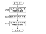
- the parking brake operation determination unit 12 first generates a parking brake operation command for the right parking brake mechanism 1R and operates the right parking brake mechanism 1R. (Step S100). Thereafter, the set time observation means 14 waits for a set fixed time (step S200). The operation command waiting unit 15 in the parking brake operation determination unit 12 determines that the parking brake operation is applied to the left parking brake mechanism 1L when the predetermined time has elapsed, that is, when it is determined that the set time observation unit 14 has set. A command is generated and the left parking brake mechanism 1L is operated (step S300). Thereafter, this process is terminated (END).
- the parking brake operation determination unit 12 in this case includes an operation completion signal monitoring unit 16 and an operation command sequential input unit 17.
- the operation completion signal monitoring means 16 inputs a parking brake operation command to either one of the left and right parking brake mechanisms 1L, 1R, and the one parking brake mechanism 1L, The presence or absence of an operation completion signal indicating that the operation of (1R) has been completed is monitored.
- a specific example of the timing at which the operation completion signal of the parking brake mechanism 1L, (1R) is output is based on the fact that the drive source 4 such as the above-described electric motor or actuator is operated by a necessary amount.
- a current sensor Sa for detecting the current of the drive source 4 is provided, and the operation completion signal monitoring means 16 uses, for example, an LUT (Look Up Table), a predetermined comparison function or conversion function of a library, etc.
- LUT Look Up Table
- the threshold is determined, for example, by a result of experiment or simulation.
- the operation command sequential input unit 17 applies to the other parking brake mechanism 1R, (1L) of the left and right parking brake mechanisms 1L, 1R. Then, a parking brake operation command is input to operate the other parking brake mechanism 1R, (1L). In this way, the left and right parking brake mechanisms 1L and 1R are continuously operated in the left-right order using the parking brake operation completion signal.
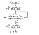
- FIG. 4 is a flowchart showing an example of using a parking brake operation completion signal in this brake device. This process starts when the parking brake request switch 13 is pressed and a parking brake operation request is transmitted to the parking brake operation determination device 12 (START). Similarly, when the parking brake operation request is input, the parking brake operation determination unit 12 first generates a parking brake operation command to the right parking brake mechanism 1R and outputs the right parking brake mechanism. 1R is operated (step a1).
- step a2 the operation completion signal monitoring means 16 stands by until a parking brake operation completion signal is received from the right parking brake mechanism 1R (step a2).
- step a2 no
- the process returns to step a2.
- step a3 the operation command sequential input means 17 generates a parking brake operation command for the left parking brake mechanism 1L, and operates the left parking brake mechanism 1L.
- the control device 2 when the parking brake request switch 13 is pressed, the control device 2 switches the left and right parking brake mechanisms 1L and 1R from the unlocked state to the parking locked state, respectively. At this time, the parking brake operation determination unit 12 in the control device 2 adjusts the timing for operating the left and right parking brake mechanisms 1L and 1R. For example, by performing processing such as rewriting the control flow of the control device 2, it is possible to reduce discomfort and discomfort due to the operating sound, and therefore, the configuration and arrangement of the components are limited as in the prior art. There is nothing. For this reason, the versatility of a brake device can be improved.
- the sound pressure level of the operating sound is carefully determined, and the left and right parking brake mechanisms 1L and 1R are operated simultaneously at the left and right or sequentially in accordance with the operating sound, thereby causing a sense of incongruity due to the operating sound. And discomfort can be reduced. For example, if the sound pressure level of the operating sound is low, the sound pressure level can be kept low even if the left and right parking brake mechanisms 1L and 1R are operated simultaneously on the left and right sides, and the generation time of the operating sound is shortened. And discomfort can be reduced.
- the vehicle configuration can be expected to have a sound shielding effect or a vibration suppression effect that is the basis of the operation sound, the sound pressure level that can be heard by the vehicle occupant even if the operation sound or the amplitude of the vibration increases is reduced. Since it can be kept low, the left and right parking brake mechanisms 1L, 1R are operated simultaneously on the left and right sides to shorten the operation sound and vibration generation time, and reduce discomfort and discomfort, as in the above example.
- the left and right parking brake mechanisms 1L and 1R are successively operated in order, so that the peak of the sound pressure level can be suppressed low, and uncomfortable and uncomfortable feeling can be reduced.
- the left and right parking brake mechanisms 1L and 1R are sequentially operated in order to suppress the operating sound and the amplitude of the vibration, thereby suppressing the peak of the sound pressure level and reducing discomfort and discomfort.
- the left and right parking brake mechanisms 1L and 1R including the drive source 4 such as an electric motor may be directly provided on the left and right service brakes 6 and 6, respectively.
- the entire brake device can be made compact, and the ease of assembly to the vehicle can be improved as compared with the first embodiment.
- the driving source 4 of each parking brake mechanism 1L, 1R for example, a direct acting actuator or an electric motor is used, and the brake shoe lever or the cam is directly driven without using a worm gear mechanism and a wire. good.
- the parking brake operation determination device 12 feels uncomfortable giving the vehicle occupant the timing to operate the left and right parking brake mechanisms 1L and 1R and the timing to operate the set mechanism in the vehicle. It is good also as what adjusts so that it may reduce.
- An example of the set mechanism is a door lock mechanism (not shown). When the door lock mechanism is also released when the parking brake is operated, an operation sound is generated even when the door lock mechanism is released. Therefore, the timing for operating the door lock mechanism and the timing for operating the parking brake mechanisms 1L and 1R. By adjusting the above, discomfort and discomfort due to the parking brake operation can be reduced.
- this electric brake device controls the left and right electric brake mechanisms 101L and 101R, the left and right parking brake mechanisms 102L and 102R, and the electric brake mechanisms 101L and 101R and the parking brake mechanisms 102L and 102R.
- a brake device having a control device 103 also referred to as an electric brake and parking brake control device 103.
- the left and right electric brake mechanisms 101L and 101R apply braking force to the left and right wheels 5 and 5 (FIG. 9) of the vehicle independently by operating the brake pedal 104, which is the brake operating means 104.
- the brake operation means 104 is not limited to a pedal input type as long as it is a means for an operator to instruct braking, and may be a button input type, a lever input type, or the like.
- the left and right electric brake mechanisms 101L and 101R are configured to be bilaterally symmetrical or have the same structure, and the left and right parking brake mechanisms 102L and 102R are also configured to be bilaterally symmetrical or have the same structure. However, for example, modifications necessary for mounting on a vehicle are allowed.
- One parking brake mechanism 102L, (102R) is assembled in association with one electric brake mechanism 101L, (101R).
- the left and right electric brake mechanisms 101L and 101R are provided on the front and rear wheels, while the left and right parking brake mechanisms 102L and 102R are provided only on either the rear wheel side or the front wheel side of the vehicle. However, the left and right parking brake mechanisms 102L and 102R may be provided for both the front and rear wheels.
- the electric brake mechanisms 101L and 101R each include an electric motor 106, a speed reduction mechanism 107 that decelerates the rotation of the electric motor 106, a linear motion mechanism 108, a brake rotor 109, and a friction pad 110.
- the electric motor 106, the speed reduction mechanism 107, and the linear motion mechanism 108 are incorporated in, for example, a housing (not shown).
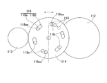
- the reduction mechanism 107 is a mechanism that reduces and transmits the rotation of the electric motor 106 to the tertiary gear 112 fixed to the rotation shaft 111, and includes a primary gear 113, an intermediate gear 114, and a tertiary gear 112.
- the speed reduction mechanism 107 decelerates the rotation of the primary gear 113 attached to the rotor shaft 106a of the electric motor 106 by a two-stage intermediate gear 114 in which two gears having different numbers of teeth are integrated.
- transmission to the tertiary gear 112 fixed to the end of the rotating shaft 111 is possible.
- the linear motion mechanism 108 converts the rotational motion output from the speed reduction mechanism 107 into a linear motion of the linear motion portion 115 having, for example, a substantially cylindrical shape or a columnar shape by a feed screw mechanism, and applies friction pads to the brake rotor 109 This is a mechanism for abutting or separating 110.
- the linearly moving portion 115 is supported so as to be free of rotation and movable in the axial direction indicated by the arrow A1.
- a friction pad 110 is provided on the outboard side (left or right side of the vehicle) end of the linear motion unit 115.
- the parking brake mechanisms 102L and (102R) can be switched between a parking lock state in which the braking force of the electric brake mechanisms 101L and (101R) is prevented from loosening and an unlocked state in which the braking force is allowed to loosen. Has been.
- the parking brake mechanisms 102L, (102R) include a lock member 116 and an actuator 117 that switches and drives the lock member 116.
- FIG. 7A is a schematic view of the main part of the parking brake mechanism as seen in plan view
- FIG. 7B is an enlarged cross-section of the locking hole 118 in FIG. 7A cut along the circumferential direction and viewed from the outboard side.
- FIG. 7A a plurality (six in this example) of locking holes 118 are formed at regular intervals in the circumferential direction on the end face of the intermediate gear 114 on the outboard side.
- Each locking hole 118 is formed in a long hole shape extending along the circumferential direction.
- the lock member 116 is configured to be able to be locked in any one of the locking holes 118.
- Each locking hole 118 has a bottomed cylindrical hole portion 118a having a flat bottom portion and an inclined hole portion 118b connected to the bottomed cylindrical hole portion 118a.
- the inclined hole portion 118b is formed in a cross-sectional shape that is inclined so as to reach the outboard side as it is separated from the portion connected to the bottomed cylindrical hole portion 118a in the circumferential direction.
- a linear solenoid is applied as the actuator 117.
- the actuator 117 moves the lock member (solenoid pin) 116 from the inside of the actuator 117 and fits into the bottomed cylindrical hole 118 a of the locking hole 118 formed in the intermediate gear 114.
- the parking lock state is established.
- a part or all of the lock member 116 is retracted into the actuator 117 and is detached from the locking hole 118, whereby the rotation of the intermediate gear 114 is allowed and the unlocked state is achieved.
- the parking brake mechanism is activated by generating a pressing force larger than the required pressing force required from the braking force required for stopping by the electric brake mechanisms 101L, 101R (FIG. 6), and then operating the actuator 117 to lock the locking member. 116 is advanced from the inside of the actuator 117 as described above. However, at this time, there is no guarantee that the locking member 116 is locked in any one of the plurality of locking holes 118 opened in the intermediate gear 114. However, even when the lock member 116 is not locked in the bottomed cylindrical hole 118a of the lock hole 118, the lock member 116 is fitted into the lock hole 118 and locked as follows.
- FIG. 8A is a diagram schematically showing the electric brake device when parking is not locked
- FIG. 8B is a diagram schematically showing the parking lock state of the electric brake device. From the state shown in FIG. 8A, after the actuator 117 is operated to move the lock member 116 to contact the intermediate gear 114 and then the rotational drive of the electric motor 106 is stopped, the friction pad 110 causes the reaction force from the brake rotor 109 to react. The linear motion part 115 of the linear motion mechanism 108 is pushed back to the inboard side.
- This reaction force causes the gears 112, 114, 113 to rotate in the pressure reducing direction. Even if the lock member 116 is advanced at the phase of the intermediate gear 114 where there is no locking hole 118, that is, the circumferential position or the inclined hole 118b, the gear 114 rotates in the pressure reducing direction. The tip of the locking member 116 slides along the inclined hole 118b (FIG. 7B) while being pushed out, and finally the position of the locking member 116 and the bottomed cylindrical hole 118a of the locking hole 118 (FIG. 7B). The phase (position) matches (FIG. 8B). Even if the intermediate gear 114 further rotates in the pressure reducing direction, as shown in FIGS. 7A and 7B, the side surface of the lock member 116 is pressed against the circumferential end 118aa of the bottomed cylindrical hole portion 118a. Further rotation of 114 is prevented.
- the rotation of the intermediate gear 114 caused by the pushing back of the linear motion portion 115 by the reaction force causes the position of the lock member 116 and the phase of the locking hole 118 to match, and the lock member 116 is in the bottomed cylindrical hole portion 118a.
- the necessary pressing force is prevented from decreasing.
- FIG. 9 is a block diagram of a control system for explaining a normal service brake operation and the like of the electric brake device.
- the control device 103 of this electric brake device has basic control means 103a.
- the control device 103 is configured by a computer having a processor, a ROM (Read Only Memory) having a program executed by the processor, and other electronic circuits such as a RAM (Random Access Memory) and a coprocessor (Co-Processor).
- the basic control means 103a operates the electric motors 106 of the left and right electric brake mechanisms 101L and 101R by operating the brake operation means 104 by the driver, and presses the friction pad 110 against the brake rotor 109 to give a braking force.
- FIG. 10 is a block diagram of the control system of this electric brake device, and the brake operation means 104 and the basic control means 103a are omitted from FIG. 9 for easy understanding.
- the control device 103 of this electric brake device includes a parking brake operation determination device 119 and left and right brake press generators 120L and 120R.
- the parking brake request switch 121 provided on the console panel of the vehicle is operated.
- the parking brake operation request generated thereby is input to the parking brake operation determination unit 119.
- the parking brake operation determination unit 119 of this example generates left and right brake press request signals to the left and right brake press generators 120L and 120R, respectively.
- the left and right brake press generators 120L and 120R output left and right brake press commands in response to left and right brake press requests.
- the left and right brake pressing commands are switched to the set pressing force. These left and right brake pressing commands are input to the left and right electric brake mechanisms 101L and 101R, respectively.
- the left and right electric brake mechanisms 101L and 101R drive the electric motor 106 according to the left and right brake pressing commands to generate a pressing force of the friction pad 110.
- the parking brake operation determination device 119 detects the feedback value of the left and right pressing forces. For example, the relationship between the pressing force and the electric motor 106 current is recorded in a relationship setting unit (not shown).
- a current sensor Sa that detects the current of the electric motor 106 is provided, and the parking brake operation determination unit 119 converts the current detected by the current sensor Sa into, for example, a predetermined comparison function or conversion function of a LUT (Look Up Table) or a library.
- the feedback value of the left and right pressing force can be calculated by applying to the relationship setting means.
- Each electric brake mechanism 101L, 101R is provided with a load sensor (not shown) such as a strain sensor that detects a reaction force from the brake rotor 109, and the parking brake operation determination unit 119 is in direct proportion to the pressing force.
- a feedback value may be obtained by detecting a detection value of each of the load sensors in the relationship.
- the parking brake operation determination unit 119 compares a pressing force required when the parking brake is set in advance (referred to as a pressing force threshold) and feedback values of the left and right pressing forces.
- a pressing force threshold a pressing force required when the parking brake is set in advance
- the parking brake operation determining unit 119 determines that the feedback values of both the left and right pressing forces exceed the pressing force threshold value
- the parking brake operation determining unit 119 generates parking brake operation commands for the left and right parking brake mechanisms 102L and 102R, respectively.
- processing such as rewriting the control flow of the control device 103, it is possible to reduce discomfort and discomfort caused by the operating sound, so that the configuration and arrangement of the electric motor and the speed reduction mechanism as in the prior art Is not limited. For this reason, the versatility of the electric brake device can be improved.
- FIG. 11 is a flowchart showing a process in which the control device of the electric brake device makes a left and right brake pressing request at the same time, and the left and right parking brake mechanisms are operated simultaneously at the left and right or sequentially in the left and right order.
- the operation timings of the left and right parking brake mechanisms may be the same on the left and right, or may be made sequentially in the left-right order.
- the left and right brake press requests are signals input from the parking brake operation determination unit 119 to the left and right brake press generators 120L and 120R.
- the left and right brake press generators 120L and 120R receive the left and right brake press requests, and output the brake press commands to the left and right electric brake mechanisms 101L and 101R, respectively, to generate the set pressing force. .
- This process is started by operating the parking brake request switch 121 (START), and when the parking brake operation request is input, the parking brake operation determination unit 119 generates left and right brake pressing requests (step S1). .
- the left and right brake press generators 120L and 120R change the output of the left and right brake press commands from the press command zero (a press command indicating zero press), which is necessary for parking braking. Switch to command.
- the left and right brake pressing commands are input to the left and right electric brake mechanisms 101L and 101R, respectively.
- the left and right electric brake mechanisms 101L and 101R generate a pressing force in accordance with the left and right brake pressing commands.
- the left and right pressing forces are output as left and right pressing feedback values from the left and right electric brake mechanisms 101L and 101R, respectively.
- the parking brake operation determination unit 119 applies the current detected by the current sensor Sa to the relationship setting unit to obtain left and right pressing feedback values (step S2).
- the parking brake operation determination unit 119 compares the pressing force threshold value with the left and right pressing feedback values (step S3).
- the parking brake operation determining unit 119 determines parking brake operation commands for the left and right parking brake mechanisms 102L and 102R, respectively. It is generated at the given timing (step S4).
- the predetermined timing is, for example, a command generation timing that can suppress a sound pressure level that can be heard by a vehicle occupant from a test result and reduce a sense of discomfort and discomfort of the occupant.
- step S3 when the parking brake operation determination device 119 determines that the feedback value of the pressing force does not exceed the pressing force threshold value in either the left or right (step S3: no), the process returns to step S2, and the parking brake operation determination device. 119 again detects the feedback values of the left and right pressing forces, and waits for both feedback values to exceed the pressing force threshold.
- step S3 description of processing such as error processing described above is omitted when conditions for a certain time cannot be satisfied, but error processing or the like is added as necessary.
- step S4 when the parking brake operation command is generated simultaneously on the left and right, the parking brake operation command is generated for the left and right parking brake mechanisms 102L and 102R when executing step S4.
- FIG. 12 shows a process when the parking brake operation command is continuously generated in the left-right order in step S4.
- the parking brake operation determination unit 119 first generates a parking brake operation command for the right parking brake mechanism 102R (step S4-1).
- the parking brake operation determination unit 119 waits for a time set in order to realize a timing for reducing discomfort and discomfort (step S4-2).
- step S4-3 This set time is set, for example, based on results of experiments and simulations.
- the parking brake operation determination unit 119 generates a parking brake operation command for the left parking brake mechanism 102L (step S4-3). Thereafter, this process is terminated (END).
- the other steps S1 to S3 are the same as in FIG.
- the following example in which steps S1 to S3 are omitted is the same as in FIG.
- the parking brake operation determination unit 119 outputs a parking brake operation completion signal to check whether or not the lock member 116 of the parking brake mechanisms 102L and 102R is locked in the locking hole 118. It may be used as a condition for proceeding to the next control step.
- the parking brake operation completion signal is a signal based on, for example, that one or both of the electric motor 106 and the actuator 117 are operated as necessary.
- step S4 in FIG. 11 is replaced with step S4-6 from step S4-4 in FIG. That is, as shown in FIG. 13, the parking brake operation determination unit 119 first generates a parking brake operation command to the right parking brake mechanism 102R (step S4-4), and the parking brake operation 102R of the right parking brake mechanism 102R is parked. Wait until a brake operation completion signal is obtained (step S4-5). When the parking brake operation determining unit 119 confirms the parking brake operation completion signal (step S4-5: yes), it generates a parking brake operation command for the remaining left parking brake mechanism 102L (step S4-6).
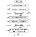
- the parking brake operation determination unit 119 When the parking brake operation request is transmitted, the parking brake operation determination unit 119 generates a right brake pressing request (step S5). In response to this right brake press request, the right brake press generator 120R switches the right brake press command from the zero press command to a preset press command necessary for parking braking.
- the right brake pressing command is input to the right electric brake mechanism 101R, and the right electric brake mechanism 101R generates a pressing force according to the right brake pressing command.
- the pressing force at this time is output as a right pressing feedback value, and the parking brake operation determination unit 119 detects the right pressing feedback value (step S6).
- the parking brake operation determination unit 119 compares the pressing force threshold value with the right pressing feedback value (step S7).
- step S7 When it is determined that the right pressing feedback value is equal to or less than the pressing force threshold (step S7: no), the process returns to step S6.
- the parking brake operation determining unit 119 confirms that the right pressing feedback value exceeds the pressing force threshold value (step S7: yes)
- the parking brake operation determining unit 119 generates a left brake pressing request (step S8).
- the left brake pressure generator 120L switches the left brake pressure command from a zero pressure command to a preset pressure command necessary for parking braking.
- the left electric brake mechanism 101L generates a pressing force in accordance with the left brake pressing command.
- the parking brake operation determination unit 119 detects the left pressing feedback value output from the left electric brake mechanism 101L (step S9). Next, the parking brake operation determination unit 119 compares the pressing force threshold value with the left pressing feedback value (step S10). If it is determined that the left pressing feedback value is equal to or less than the pressing force threshold value (step S10: no), the process returns to step S9.
- step S10 When the parking brake operation determining unit 119 confirms that the left pressing feedback value has exceeded the pressing force threshold (step S10: yes), the parking brake operation determining unit 119 performs parking to the left and right parking brake mechanisms 102L and 102R.
- a brake operation command is generated at a predetermined timing (step S11). At this time, the timing for generating the left and right parking brake operation commands is set as the command generation timing for reducing the above-mentioned uncomfortable feeling and discomfort. Thereafter, this process is terminated (END).
- step S11 when the parking brake operation command is generated at the same time on the left and right, the parking brake operation determining unit 119 performs parking for the left and right parking brake mechanisms 102L and 102R when executing step S11, as in step S4. Generate a brake activation command.
- steps S4-1 to S4-3 shown in FIG. 12 are similarly performed in step S11.
- step S11 is performed in step S4- in FIG. Replace 4 with step S4-6.
- FIG. 15 is a block diagram of a control system of the electric brake device according to the modification of the third embodiment.
- the electric brake device control device 103A includes a parking brake operation determination unit 119 and left and right electric brake and parking brake control devices 122L and 122R.
- Brake pressure generators 120L and 120R are provided in the electric brake and parking brake control devices 122L and 122R, respectively, and a parking brake operation determination unit 119 is provided outside the electric brake and parking brake control devices 122L and 122R.
- the parking brake operation determination device 119 has been handled on the assumption that it exists inside the electric brake and parking brake control device.
- the parking brake operation determining unit 119 is inside or outside the electric brake and parking brake control device.
- the parking brake operation determination device 119 is not necessarily provided either inside or outside.
- the parking brake operation determination unit 119 is replaced with the electric brake and parking brake control device 122L, It is more appropriate to provide it outside of 122R.
- the reason is that an element for simultaneously monitoring the states of the left and right electric brake mechanisms 101L and 101R and the parking brake mechanisms 102L and 102R is necessary. This is because it is more practical to provide the determination unit 119 because a simple configuration can be taken.
- the parking brake operation determination device is provided inside the electric brake and parking brake control device, either the left or right electric brake and parking brake control device are monitored simultaneously as described above, or the left and right electric brakes are And the parking brake control device communicate with each other to monitor the pressure feedback value, adjust each operation timing, or either one of the left and right has the priority represented by the master slave, and the pressure feedback value by communication It is necessary to determine the timing of each operation. Therefore, by adopting this configuration, the control and configuration become complicated, and there is no advantage from the viewpoint of reducing discomfort and discomfort due to the operating sound.
- the control flow can be controlled as described above.
- the parking brake operation command and the information on the feedback value of the pressing force are transmitted to the parking brake mechanisms 102L and 102R and the electric brake mechanisms 101L and 101R via the electric brake and parking brake control devices 122L and 122R. Exchanged with the brake operation determination device 119.
- each of the electric brake and parking brake control devices 122L and 122R, and an integrated controller (not shown) of the higher-level vehicle and the parking brake operation determination unit 119 are respectively connected by mutual communication means such as CAN bus communication. It is realistic to connect and send and receive necessary information in a batch. Therefore, there is no additional signal line due to an increase in the number of information.
- the parking brake operation command and the feedback value of the pressing force are directly exchanged with the parking brake operation determination unit 119, the electric brake mechanisms 101L and 101R, and the parking brake mechanisms 102L and 102R without using the electric brake and parking brake control devices 122L and 122R.
- the electric brake and parking brake control device includes a parking brake operation determination unit 119 and a brake press generator 120 (for the right brake in the illustrated example). And a brake pedal pressing command generator 124 and a pressing command adder 123. Based on the brake pedal pressing request input by the brake pedal 104, the brake pedal pressing command generator 124 generates a brake pedal pressing command. This brake pedal pressing command is input to the pressing command adder 123.
- the parking brake operation determination unit 119 receives the parking brake operation request and generates a brake pressing request (for the right brake in the example in the figure) at a predetermined timing.
- the brake press generator 120 inputs a necessary press command (referred to as a parking brake press command) to the press command adder 123.
- the press command adder 123 the two press commands are added and output as the entire press command.
- a press command selector may be used instead of the press command adder 123.
- the press command selector can be replaced with the press command adder 123, and selects a larger one of the two input press commands and outputs it as the entire press command.
- the press command adder 123 when the parking brake mechanism is used, for example, even when the vehicle is likely to undesirably move backward on a slope, if the brake pedal is depressed, the braking force immediately increases and the vehicle moves backward. Can be prevented. However, if the pressing force generated during parking brake is large, there is a high possibility that the brake will be locked.
- the control flow is almost the same as in FIG. What is changed in the signal flow is a portion related to the brake pressing command generator 120.
- a parking brake operation request is directly input to the brake press generator 120, and the parking brake press command is immediately set to a predetermined press required for parking brake from zero to right. Each is switched to a command.
- the processing after step S1 in FIG. 11 is the same as when the control flow in FIG. 11 is executed using the control block in FIG.
- the command timing for parking brake operation should be taken into account. You may decide.
- a door lock can be considered. When the parking brake is operated in a state where an occupant is on the vehicle, it is more convenient for the occupant to release the door lock.
- the left and right wheels that independently apply braking force to the left and right wheels in the vehicle and maintain the vehicle in a stopped state.
- a parking brake operation determination device that adjusts the mutual timing for operating the left and right brake mechanisms to reduce the uncomfortable feeling given to the vehicle occupant
- the left and right electric brake mechanisms that can independently add braking force to the left and right wheels in the vehicle and are operated by a brake operation means by the driver;
- Left and right parking brake mechanisms that can be switched independently between left and right parking lock states that prevent the braking force of the left and right electric brake mechanisms from loosening and unlock states that allow the braking force to loosen;
- a control device for controlling the electric brake mechanism and the parking brake mechanism;
Landscapes
- Engineering & Computer Science (AREA)
- Mechanical Engineering (AREA)
- Transportation (AREA)
- General Engineering & Computer Science (AREA)
- Regulating Braking Force (AREA)
- Braking Systems And Boosters (AREA)
- Valves And Accessory Devices For Braking Systems (AREA)
Abstract
L'invention porte sur un dispositif de frein qui peut améliorer la souplesse du dispositif et réduire la sensation incongrue provoquée par le son du fonctionnement d'un frein de stationnement. Le dispositif de frein comprend des mécanismes de frein de stationnement gauche et droit (1G, 1D), qui appliquent séparément une force de freinage à des roues gauche et droite d'un véhicule et qui maintiennent le véhicule dans un état arrêté, et un dispositif de commande (2), qui commande le mécanisme de frein de stationnement (1G, 1D). Le dispositif de commande (2) est pourvu d'un dispositif de détermination d'actionnement de frein de stationnement (12), qui ajuste les synchronisations auxquelles les mécanismes de frein de stationnement gauche et droit (1G, 1D) sont amenés à fonctionner, de façon à réduire la sensation incongrue subie par un passager du véhicule.
Priority Applications (3)
| Application Number | Priority Date | Filing Date | Title |
|---|---|---|---|
| EP15783276.7A EP3135548B1 (fr) | 2014-04-22 | 2015-04-13 | Dispositif de frein |
| CN201580020709.0A CN106458174B (zh) | 2014-04-22 | 2015-04-13 | 制动装置 |
| US15/296,492 US10247268B2 (en) | 2014-04-22 | 2016-10-18 | Brake device |
Applications Claiming Priority (4)
| Application Number | Priority Date | Filing Date | Title |
|---|---|---|---|
| JP2014088478A JP6377397B2 (ja) | 2014-04-22 | 2014-04-22 | パーキングブレーキ装置 |
| JP2014-088477 | 2014-04-22 | ||
| JP2014-088478 | 2014-04-22 | ||
| JP2014088477A JP6393069B2 (ja) | 2014-04-22 | 2014-04-22 | パーキングブレーキ付き電動ブレーキ装置 |
Related Child Applications (1)
| Application Number | Title | Priority Date | Filing Date |
|---|---|---|---|
| US15/296,492 Continuation US10247268B2 (en) | 2014-04-22 | 2016-10-18 | Brake device |
Publications (1)
| Publication Number | Publication Date |
|---|---|
| WO2015163179A1 true WO2015163179A1 (fr) | 2015-10-29 |
Family
ID=54332346
Family Applications (1)
| Application Number | Title | Priority Date | Filing Date |
|---|---|---|---|
| PCT/JP2015/061402 WO2015163179A1 (fr) | 2014-04-22 | 2015-04-13 | Dispositif de frein |
Country Status (4)
| Country | Link |
|---|---|
| US (1) | US10247268B2 (fr) |
| EP (1) | EP3135548B1 (fr) |
| CN (1) | CN106458174B (fr) |
| WO (1) | WO2015163179A1 (fr) |
Cited By (2)
| Publication number | Priority date | Publication date | Assignee | Title |
|---|---|---|---|---|
| CN110173526A (zh) * | 2019-05-16 | 2019-08-27 | 广东机电职业技术学院 | 一种新型结构制动器 |
| WO2020111163A1 (fr) * | 2018-11-30 | 2020-06-04 | 株式会社アドヴィックス | Dispositif de commande de freinage |
Families Citing this family (5)
| Publication number | Priority date | Publication date | Assignee | Title |
|---|---|---|---|---|
| JP2018144576A (ja) * | 2017-03-03 | 2018-09-20 | Ntn株式会社 | 車両制御装置 |
| FR3099903B1 (fr) * | 2019-08-12 | 2021-07-16 | Psa Automobiles Sa | Dispositif de frein de parking de vehicule automobile muni d'un systeme d'amortissement des chocs |
| CN110525401A (zh) * | 2019-08-15 | 2019-12-03 | 芜湖伯特利汽车安全系统股份有限公司 | 一种提升车辆制动舒适性的方法 |
| US20230106755A1 (en) * | 2021-10-01 | 2023-04-06 | Ford Global Technologies, Llc | Methods and apparatus to extend brake life cycle |
| DE102022204631A1 (de) | 2022-05-11 | 2023-11-16 | Volkswagen Aktiengesellschaft | Wärmebereitstellung bei einem stehenden Elektrofahrzeug |
Citations (3)
| Publication number | Priority date | Publication date | Assignee | Title |
|---|---|---|---|---|
| JP2004175164A (ja) * | 2002-11-26 | 2004-06-24 | Hitachi Ltd | 電動ブレーキ,その制御装置及び電動ブレーキの制御方法 |
| JP2005017453A (ja) * | 2003-06-24 | 2005-01-20 | Murata Mach Ltd | 画像形成装置 |
| JP2009149209A (ja) * | 2007-12-20 | 2009-07-09 | Toyota Motor Corp | ワイパ装置及びワイパ用モータ駆動方法 |
Family Cites Families (13)
| Publication number | Priority date | Publication date | Assignee | Title |
|---|---|---|---|---|
| CN1098055A (zh) * | 1993-03-31 | 1995-02-01 | 丰田自动车株式会社 | 车辆制动压力控制机构 |
| JPH06286595A (ja) | 1993-03-31 | 1994-10-11 | Toyota Motor Corp | 車輪過大スリップ防止装置 |
| JPH06286596A (ja) | 1993-03-31 | 1994-10-11 | Toyota Motor Corp | アンチロック型液圧ブレーキ装置 |
| US20070084682A1 (en) * | 2001-07-31 | 2007-04-19 | Griffith T T | Parking brake adjustment for an aircraft having an electric brake system |
| JP4370775B2 (ja) * | 2002-12-17 | 2009-11-25 | 日産自動車株式会社 | 複合ブレーキの協調制御装置 |
| JP4680643B2 (ja) | 2005-03-18 | 2011-05-11 | 本田技研工業株式会社 | 車両の電動パーキングブレーキシステム |
| DE202007017096U1 (de) * | 2007-12-05 | 2008-02-14 | Edscha Ag | Kraftfahrzeug-Feststellbremse |
| DE102010003232A1 (de) | 2009-04-06 | 2010-10-07 | Continental Teves Ag & Co. Ohg | Verfahren zum Betreiben einer Bremsanlage, Bremsanlage und Kraftfahrzeug |
| JP2010241271A (ja) | 2009-04-06 | 2010-10-28 | Toyota Motor Corp | ブレーキ制御装置 |
| JP2012193802A (ja) * | 2011-03-17 | 2012-10-11 | Akebono Brake Ind Co Ltd | パーキング機構付電動式ブレーキ装置 |
| JP5923969B2 (ja) | 2011-12-22 | 2016-05-25 | 株式会社アドヴィックス | 電動パーキングブレーキ装置 |
| JP5834993B2 (ja) * | 2012-02-20 | 2015-12-24 | 日産自動車株式会社 | 車両のパークロック装置 |
| JP5964701B2 (ja) * | 2012-08-31 | 2016-08-03 | 日立オートモティブシステムズ株式会社 | ブレーキ装置 |
-
2015
- 2015-04-13 WO PCT/JP2015/061402 patent/WO2015163179A1/fr active Application Filing
- 2015-04-13 CN CN201580020709.0A patent/CN106458174B/zh not_active Expired - Fee Related
- 2015-04-13 EP EP15783276.7A patent/EP3135548B1/fr active Active
-
2016
- 2016-10-18 US US15/296,492 patent/US10247268B2/en not_active Expired - Fee Related
Patent Citations (3)
| Publication number | Priority date | Publication date | Assignee | Title |
|---|---|---|---|---|
| JP2004175164A (ja) * | 2002-11-26 | 2004-06-24 | Hitachi Ltd | 電動ブレーキ,その制御装置及び電動ブレーキの制御方法 |
| JP2005017453A (ja) * | 2003-06-24 | 2005-01-20 | Murata Mach Ltd | 画像形成装置 |
| JP2009149209A (ja) * | 2007-12-20 | 2009-07-09 | Toyota Motor Corp | ワイパ装置及びワイパ用モータ駆動方法 |
Cited By (4)
| Publication number | Priority date | Publication date | Assignee | Title |
|---|---|---|---|---|
| WO2020111163A1 (fr) * | 2018-11-30 | 2020-06-04 | 株式会社アドヴィックス | Dispositif de commande de freinage |
| JP2020083287A (ja) * | 2018-11-30 | 2020-06-04 | 株式会社アドヴィックス | 制動制御装置 |
| JP7222233B2 (ja) | 2018-11-30 | 2023-02-15 | 株式会社アドヴィックス | 制動制御装置 |
| CN110173526A (zh) * | 2019-05-16 | 2019-08-27 | 广东机电职业技术学院 | 一种新型结构制动器 |
Also Published As
| Publication number | Publication date |
|---|---|
| EP3135548B1 (fr) | 2020-12-02 |
| CN106458174A (zh) | 2017-02-22 |
| EP3135548A4 (fr) | 2017-12-06 |
| CN106458174B (zh) | 2019-05-28 |
| US10247268B2 (en) | 2019-04-02 |
| US20170037919A1 (en) | 2017-02-09 |
| EP3135548A1 (fr) | 2017-03-01 |
Similar Documents
| Publication | Publication Date | Title |
|---|---|---|
| WO2015163179A1 (fr) | Dispositif de frein | |
| CN109952240B (zh) | 机动车辆系统、控制方法、存储介质和控制器系统 | |
| CN110494333B (zh) | 用于电动驻车制动器的机动车辆控制单元 | |
| WO2016178428A1 (fr) | Système de frein électrique | |
| JP4887010B2 (ja) | 駐車ブレーキの油圧作動用の装置と、そのような装置を操作するための方法 | |
| JP5126990B2 (ja) | 非常時車両停止のための安全制動装置およびそれを用いた車両制動装置 | |
| JP2016533964A (ja) | フェールセーフティと利用性の向上した運転アシストシステム | |
| JP2002308084A (ja) | ストロークシミュレータ | |
| JP2015193357A (ja) | 電動式ブレーキシステム、電動式ブレーキシステムを搭載した車両、及び電動式ブレーキシステムの制御方法 | |
| JP2019038302A (ja) | 電動ブレーキ装置 | |
| US10507810B2 (en) | Electric brake device | |
| KR101601462B1 (ko) | 차량의 전기유압식 브레이크 시스템 | |
| KR101272592B1 (ko) | 차량용 하이브리드 브레이크 | |
| JP2017171215A (ja) | ブレーキシステム | |
| JP6393069B2 (ja) | パーキングブレーキ付き電動ブレーキ装置 | |
| JP5013262B2 (ja) | ディスクブレーキ装置 | |
| JP6377397B2 (ja) | パーキングブレーキ装置 | |
| JP2001278018A (ja) | 自動車の電気機械形ブレーキシステムの出力を制御するための方法 | |
| KR101382996B1 (ko) | 전자식 주차 브레이크를 이용한 차량의 회전반경 감소 장치 및 방법 | |
| JP2005525967A (ja) | 常用ブレーキシステム及びパーキングブレーキシステムを備える車両ブレーキシステム | |
| JP4508117B2 (ja) | ブレーキシステム | |
| JP2007069649A (ja) | ブレーキ・バイ・ワイヤ装置 | |
| JP2007118917A (ja) | 車両用電動ブレーキ装置 | |
| TWI832177B (zh) | 一種控制煞車以避免煞車失效的交通工具及其方法 | |
| KR100290383B1 (ko) | 무인차량용제동장치 |
Legal Events
| Date | Code | Title | Description |
|---|---|---|---|
| 121 | Ep: the epo has been informed by wipo that ep was designated in this application |
Ref document number: 15783276 Country of ref document: EP Kind code of ref document: A1 |
|
| NENP | Non-entry into the national phase |
Ref country code: DE |
|
| REEP | Request for entry into the european phase |
Ref document number: 2015783276 Country of ref document: EP |
|
| WWE | Wipo information: entry into national phase |
Ref document number: 2015783276 Country of ref document: EP |