WO2015163179A1 - Brake device - Google Patents
Brake device Download PDFInfo
- Publication number
- WO2015163179A1 WO2015163179A1 PCT/JP2015/061402 JP2015061402W WO2015163179A1 WO 2015163179 A1 WO2015163179 A1 WO 2015163179A1 JP 2015061402 W JP2015061402 W JP 2015061402W WO 2015163179 A1 WO2015163179 A1 WO 2015163179A1
- Authority
- WO
- WIPO (PCT)
- Prior art keywords
- parking brake
- brake
- parking
- mechanisms
- vehicle
- Prior art date
Links
Images


Classifications
-
- B—PERFORMING OPERATIONS; TRANSPORTING
- B60—VEHICLES IN GENERAL
- B60T—VEHICLE BRAKE CONTROL SYSTEMS OR PARTS THEREOF; BRAKE CONTROL SYSTEMS OR PARTS THEREOF, IN GENERAL; ARRANGEMENT OF BRAKING ELEMENTS ON VEHICLES IN GENERAL; PORTABLE DEVICES FOR PREVENTING UNWANTED MOVEMENT OF VEHICLES; VEHICLE MODIFICATIONS TO FACILITATE COOLING OF BRAKES
- B60T7/00—Brake-action initiating means
- B60T7/02—Brake-action initiating means for personal initiation
- B60T7/08—Brake-action initiating means for personal initiation hand actuated
- B60T7/10—Disposition of hand control
- B60T7/107—Disposition of hand control with electrical power assistance
-
- F—MECHANICAL ENGINEERING; LIGHTING; HEATING; WEAPONS; BLASTING
- F16—ENGINEERING ELEMENTS AND UNITS; GENERAL MEASURES FOR PRODUCING AND MAINTAINING EFFECTIVE FUNCTIONING OF MACHINES OR INSTALLATIONS; THERMAL INSULATION IN GENERAL
- F16D—COUPLINGS FOR TRANSMITTING ROTATION; CLUTCHES; BRAKES
- F16D65/00—Parts or details
- F16D65/14—Actuating mechanisms for brakes; Means for initiating operation at a predetermined position
- F16D65/16—Actuating mechanisms for brakes; Means for initiating operation at a predetermined position arranged in or on the brake
- F16D65/18—Actuating mechanisms for brakes; Means for initiating operation at a predetermined position arranged in or on the brake adapted for drawing members together, e.g. for disc brakes
-
- B—PERFORMING OPERATIONS; TRANSPORTING
- B60—VEHICLES IN GENERAL
- B60T—VEHICLE BRAKE CONTROL SYSTEMS OR PARTS THEREOF; BRAKE CONTROL SYSTEMS OR PARTS THEREOF, IN GENERAL; ARRANGEMENT OF BRAKING ELEMENTS ON VEHICLES IN GENERAL; PORTABLE DEVICES FOR PREVENTING UNWANTED MOVEMENT OF VEHICLES; VEHICLE MODIFICATIONS TO FACILITATE COOLING OF BRAKES
- B60T13/00—Transmitting braking action from initiating means to ultimate brake actuator with power assistance or drive; Brake systems incorporating such transmitting means, e.g. air-pressure brake systems
- B60T13/74—Transmitting braking action from initiating means to ultimate brake actuator with power assistance or drive; Brake systems incorporating such transmitting means, e.g. air-pressure brake systems with electrical assistance or drive
- B60T13/741—Transmitting braking action from initiating means to ultimate brake actuator with power assistance or drive; Brake systems incorporating such transmitting means, e.g. air-pressure brake systems with electrical assistance or drive acting on an ultimate actuator
-
- B—PERFORMING OPERATIONS; TRANSPORTING
- B60—VEHICLES IN GENERAL
- B60T—VEHICLE BRAKE CONTROL SYSTEMS OR PARTS THEREOF; BRAKE CONTROL SYSTEMS OR PARTS THEREOF, IN GENERAL; ARRANGEMENT OF BRAKING ELEMENTS ON VEHICLES IN GENERAL; PORTABLE DEVICES FOR PREVENTING UNWANTED MOVEMENT OF VEHICLES; VEHICLE MODIFICATIONS TO FACILITATE COOLING OF BRAKES
- B60T13/00—Transmitting braking action from initiating means to ultimate brake actuator with power assistance or drive; Brake systems incorporating such transmitting means, e.g. air-pressure brake systems
- B60T13/74—Transmitting braking action from initiating means to ultimate brake actuator with power assistance or drive; Brake systems incorporating such transmitting means, e.g. air-pressure brake systems with electrical assistance or drive
- B60T13/746—Transmitting braking action from initiating means to ultimate brake actuator with power assistance or drive; Brake systems incorporating such transmitting means, e.g. air-pressure brake systems with electrical assistance or drive and mechanical transmission of the braking action
-
- B—PERFORMING OPERATIONS; TRANSPORTING
- B60—VEHICLES IN GENERAL
- B60T—VEHICLE BRAKE CONTROL SYSTEMS OR PARTS THEREOF; BRAKE CONTROL SYSTEMS OR PARTS THEREOF, IN GENERAL; ARRANGEMENT OF BRAKING ELEMENTS ON VEHICLES IN GENERAL; PORTABLE DEVICES FOR PREVENTING UNWANTED MOVEMENT OF VEHICLES; VEHICLE MODIFICATIONS TO FACILITATE COOLING OF BRAKES
- B60T8/00—Arrangements for adjusting wheel-braking force to meet varying vehicular or ground-surface conditions, e.g. limiting or varying distribution of braking force
- B60T8/17—Using electrical or electronic regulation means to control braking
-
- F—MECHANICAL ENGINEERING; LIGHTING; HEATING; WEAPONS; BLASTING
- F16—ENGINEERING ELEMENTS AND UNITS; GENERAL MEASURES FOR PRODUCING AND MAINTAINING EFFECTIVE FUNCTIONING OF MACHINES OR INSTALLATIONS; THERMAL INSULATION IN GENERAL
- F16D—COUPLINGS FOR TRANSMITTING ROTATION; CLUTCHES; BRAKES
- F16D65/00—Parts or details
- F16D65/14—Actuating mechanisms for brakes; Means for initiating operation at a predetermined position
- F16D65/16—Actuating mechanisms for brakes; Means for initiating operation at a predetermined position arranged in or on the brake
- F16D65/18—Actuating mechanisms for brakes; Means for initiating operation at a predetermined position arranged in or on the brake adapted for drawing members together, e.g. for disc brakes
- F16D65/183—Actuating mechanisms for brakes; Means for initiating operation at a predetermined position arranged in or on the brake adapted for drawing members together, e.g. for disc brakes with force-transmitting members arranged side by side acting on a spot type force-applying member
-
- B—PERFORMING OPERATIONS; TRANSPORTING
- B60—VEHICLES IN GENERAL
- B60T—VEHICLE BRAKE CONTROL SYSTEMS OR PARTS THEREOF; BRAKE CONTROL SYSTEMS OR PARTS THEREOF, IN GENERAL; ARRANGEMENT OF BRAKING ELEMENTS ON VEHICLES IN GENERAL; PORTABLE DEVICES FOR PREVENTING UNWANTED MOVEMENT OF VEHICLES; VEHICLE MODIFICATIONS TO FACILITATE COOLING OF BRAKES
- B60T1/00—Arrangements of braking elements, i.e. of those parts where braking effect occurs specially for vehicles
- B60T1/005—Arrangements of braking elements, i.e. of those parts where braking effect occurs specially for vehicles by locking of wheel or transmission rotation
-
- F—MECHANICAL ENGINEERING; LIGHTING; HEATING; WEAPONS; BLASTING
- F16—ENGINEERING ELEMENTS AND UNITS; GENERAL MEASURES FOR PRODUCING AND MAINTAINING EFFECTIVE FUNCTIONING OF MACHINES OR INSTALLATIONS; THERMAL INSULATION IN GENERAL
- F16D—COUPLINGS FOR TRANSMITTING ROTATION; CLUTCHES; BRAKES
- F16D2121/00—Type of actuator operation force
- F16D2121/18—Electric or magnetic
- F16D2121/24—Electric or magnetic using motors
-
- F—MECHANICAL ENGINEERING; LIGHTING; HEATING; WEAPONS; BLASTING
- F16—ENGINEERING ELEMENTS AND UNITS; GENERAL MEASURES FOR PRODUCING AND MAINTAINING EFFECTIVE FUNCTIONING OF MACHINES OR INSTALLATIONS; THERMAL INSULATION IN GENERAL
- F16D—COUPLINGS FOR TRANSMITTING ROTATION; CLUTCHES; BRAKES
- F16D2125/00—Components of actuators
- F16D2125/18—Mechanical mechanisms
- F16D2125/20—Mechanical mechanisms converting rotation to linear movement or vice versa
- F16D2125/34—Mechanical mechanisms converting rotation to linear movement or vice versa acting in the direction of the axis of rotation
- F16D2125/42—Rack-and-worm gears
-
- F—MECHANICAL ENGINEERING; LIGHTING; HEATING; WEAPONS; BLASTING
- F16—ENGINEERING ELEMENTS AND UNITS; GENERAL MEASURES FOR PRODUCING AND MAINTAINING EFFECTIVE FUNCTIONING OF MACHINES OR INSTALLATIONS; THERMAL INSULATION IN GENERAL
- F16D—COUPLINGS FOR TRANSMITTING ROTATION; CLUTCHES; BRAKES
- F16D2125/00—Components of actuators
- F16D2125/18—Mechanical mechanisms
- F16D2125/58—Mechanical mechanisms transmitting linear movement
- F16D2125/60—Cables or chains, e.g. Bowden cables
-
- F—MECHANICAL ENGINEERING; LIGHTING; HEATING; WEAPONS; BLASTING
- F16—ENGINEERING ELEMENTS AND UNITS; GENERAL MEASURES FOR PRODUCING AND MAINTAINING EFFECTIVE FUNCTIONING OF MACHINES OR INSTALLATIONS; THERMAL INSULATION IN GENERAL
- F16D—COUPLINGS FOR TRANSMITTING ROTATION; CLUTCHES; BRAKES
- F16D63/00—Brakes not otherwise provided for; Brakes combining more than one of the types of groups F16D49/00 - F16D61/00
- F16D63/006—Positive locking brakes
Definitions
- This invention relates to a brake device having a left and right independent mechanism, and relates to a technique for reducing operating noise when a parking brake is operated.
- Brake devices have been proposed that can generate a braking force using an electric motor as a drive source and maintain the braking force even after energization of the electric motor is stopped.
- this brake device not a little operation noise is generated when the parking brake is operated, and there is a sense of incongruity or discomfort due to this operation sound.
- Specific examples of the operating sound include, for example, a sound emitted from a ratchet attached to the press generation mechanism, a sound at the time of fastening the lock mechanism, and a sound at the time of pressure increase that generates a braking force. There was a need to reduce discomfort.
- Patent Document 3 there is a method of giving a sense of security by impressing that this is a normal phenomenon caused by the operation of the parking brake, and making the operation sound itself difficult to notice with an electronic sound.
- Patent Document 1 that optimizes the configuration and arrangement of the motor and the reduction gear
- the configuration and arrangement of the motor and the reduction gear are limited, and the versatility of the electric brake device with a parking brake is lowered.
- Patent Document 2 in which the lock mechanism is provided with an elastic portion, the structure of the apparatus becomes complicated and the manufacturing cost increases.
- the operation noise cannot be suppressed.
- Patent Document 3 that generates the electronic sound, for example, depending on the size or frequency band of the electronic sound, the operating sound when the parking brake is operated may not be appropriately suppressed. It may be the cause of operating noise. Due to these operating sounds, the driver or the like is uncomfortable or uncomfortable.
- An object of the present invention is to provide a brake device that can improve the versatility of the device and can reduce discomfort and discomfort caused by the operating sound of a parking brake.
- the brake device applies left and right parking brake mechanisms 1L and 1R that independently apply braking force to the left and right wheels of the vehicle and maintains the vehicle in a stopped state, and these parking brake mechanisms 1L. , 1R, and a braking device including a control device 2 for controlling 1R,
- the control device 2 is provided with a parking brake operation determination device 12 for adjusting the mutual timing for operating the left and right parking brake mechanisms 1L and 1R so as to reduce the uncomfortable feeling given to the vehicle occupant.
- the operation timing can also be determined independently. Therefore, focusing on the operation sound (hereinafter simply referred to as “operation sound”) that is most likely to cause discomfort and discomfort among the operation sounds when the parking brake is operated, for example, the generation timing of the operation command is By controlling, it is possible to manage the generation timing of the operation sound, and to reduce discomfort and discomfort given to the driver or the like even if the same operation sound is generated. Therefore, the uncomfortable feeling and discomfort caused by the operating sound of the parking brake can be reduced.
- operation sound hereinafter simply referred to as “operation sound”
- the generation timing of the operation command is By controlling, it is possible to manage the generation timing of the operation sound, and to reduce discomfort and discomfort given to the driver or the like even if the same operation sound is generated. Therefore, the uncomfortable feeling and discomfort caused by the operating sound of the parking brake can be reduced.
- the control device 2 when the driver operates, for example, the parking brake request switch 13 or the like, the control device 2 switches the left and right parking brake mechanisms 1L and 1R from the unlocked state to the parking locked state, respectively.
- the parking brake operation determination unit 12 in the control device 2 adjusts the timing for operating the left and right parking brake mechanisms 1L and 1R. For example, by performing processing such as rewriting the control flow of the control device 2, it is possible to reduce discomfort and discomfort due to the operating sound, and therefore, the configuration and arrangement of the components are limited as in the prior art. There is nothing. For this reason, the versatility of a brake device can be improved.
- the generation timing of the operating sound that reduces discomfort and discomfort depends on the sound pressure level and frequency distribution of the operating sound, the arrangement and mounting method of the parking brake mechanisms 1L and 1R, the propagation path and resonance of the operating sound to the vehicle, and the state of chatter. It is set in advance when designing the vehicle.
- the sound pressure level of the operating sound is low, the sound pressure level can be kept low even if the left and right parking brake mechanisms 1L and 1R are operated simultaneously on the left and right sides, and the generation time of the operating sound is shortened. And discomfort can be reduced.
- the vehicle configuration can be expected to have a shielding effect for operating noise and a damping effect for vibration that is the source of the operating noise, the sound pressure level that can be heard by the vehicle occupant is reduced even if the amplitude of the operating noise and vibration increases. Since it can be suppressed, the left and right parking brake mechanisms 1L and 1R can be operated simultaneously on the left and right sides to shorten the operating noise and the generation time of vibration, and to reduce discomfort and discomfort, as in the above example.
- the generation time of the operation sound is the time that the operation sound is heard by the occupant.
- the generation time is one time of the normal operation.
- the generation time is twice as long as the normal operation.
- the left and right parking brake mechanisms 1L and 1R are sequentially operated at different timings to keep the sound pressure level peak low. Can reduce discomfort and discomfort.
- the sound insulation effect of the operation sound or the vibration suppression effect that causes the operation sound cannot be expected due to the vehicle configuration, specifically, the air easily propagates or resonance or chatter noise (beat noise) occurs.
- the left and right parking brake mechanisms 1L and 1R are sequentially operated in order to keep the operating sound and vibration amplitude small, thereby suppressing the peak of the sound pressure level and reducing discomfort and discomfort. Can do.
- the operating sound is in a frequency band where the passenger is not likely to feel discomfort or discomfort even if the sound pressure level is high, it is desirable to operate the left and right parking brake mechanisms 1L and 1R simultaneously. If the sound pressure level is very low and cannot be perceived if the parking brake mechanism 1L, (1R) on one side is operated, the operation sound can be perceived if the parking brake mechanisms 1L, 1R on both the left and right sides are operated. It is desirable to adopt a method of continuously operating the parking brake mechanisms 1L, 1R. As described above, in practice, it is appropriate to change the generation timing of the operation command to the parking brake mechanisms 1L and 1R at the time of vehicle design and perform a sensory survey to adopt the timing with the least discomfort and discomfort.
- the parking brake operation determination unit 12 reduces the uncomfortable feeling given to the occupant of the vehicle based on the set timing. , 1R, a parking brake operation command may be input to operate the vehicle in a parking lock state for maintaining the vehicle in a stopped state.
- the timing with the least discomfort and discomfort is set according to the results of tests, simulations, and the like.
- the parking brake operation determining device 12 is A parking brake operation command is input to one of the left and right parking brake mechanisms 1L, 1R to complete the operation of the one parking brake mechanism 1L, (1R).
- An operation completion signal monitoring means 16 for monitoring the presence or absence of an operation completion signal indicating that, When there is an operation completion signal by the operation completion signal monitoring means 16, an operation command for inputting a parking brake operation command to the other parking brake mechanism 1R, (1L) in the left and right parking brake mechanisms 1L, 1R. It is good also as what has the input means 17 sequentially.
- the parking brake operation determination device 12 inputs a parking brake operation command to one parking brake mechanism 1L, (1R)
- the operation completion signal monitoring means 16 stands by until receiving an operation completion signal.
- the operation command sequential input means 17 inputs a parking brake operation command to the other parking brake mechanism 1R, (1L).
- the parking brake operation determination unit 12 may operate the left and right parking brake mechanisms 1L and 1R simultaneously as the timing. For example, when the sound pressure level of the operating sound is low, or when the effect of shielding the operating sound or the vibration suppression effect of the operating sound can be expected depending on the vehicle configuration, the left and right parking brake mechanisms 1L and 1R are installed. By operating simultaneously, the generation time of an operation sound and a vibration can be shortened, and the discomfort and discomfort of the vehicle occupant can be reduced.
- the parking brake operation determining device 12 is Setting time observation means for determining whether a set time has elapsed by inputting a parking brake operation command to one of the left and right parking brake mechanisms 1L, 1R. 14 and When it is determined by the set time observation means 14 that the set time has elapsed, a parking brake operation command is input to the other parking brake mechanism 1R, (1L) of the left and right parking brake mechanisms 1L, 1R. It is good also as what has the operation command waiting means 15 to perform.
- the set time is determined by sensory evaluation or the like at the time of vehicle design, for example.
- the parking brake operation determination device 12 inputs a parking brake operation command to one parking brake mechanism 1L, (1R)
- the set time observation means 14 determines whether or not the set time has elapsed. judge.
- the operation command waiting unit 15 inputs a parking brake operation command to the other parking brake mechanism 1R, (1L).
- the parking brake operation determination unit 12 has a timing for operating the left and right parking brake mechanisms 1L and 1R and a timing for operating a set mechanism that generates a working sound in the vehicle. It is good also as what adjusts so that the discomfort given to the passenger
- An example of the set mechanism is a door lock mechanism.
- the vehicle door lock mechanism is When the operation sound is generated, the parking brake mechanism is operated in consideration of the operation sound of the door lock mechanism.
- the parking brake mechanism is operated while the occupant is in the vehicle, it is more convenient for the occupant to release the door lock mechanism. Therefore, when the door lock mechanism is also released when the parking brake is operated, an operation sound is generated even when the door lock mechanism is released. Therefore, the timing for operating the door lock mechanism and the parking brake mechanisms 1L and 1R are operated. By adjusting the timing (for example, operating the parking brake almost simultaneously when the door lock mechanism is operated), it is possible to reduce discomfort and discomfort due to the parking brake operation.
- the left and right electric brake mechanisms can be independently applied to the left and right wheels 5 and 5 in the vehicle and are operated by the brake operation means 104 by the driver.
- the left and right parking brake mechanisms 102L and 102R are independent of left and right in a parking lock state that prevents the braking force of the left and right electric brake mechanisms 101L and 101R from loosening and an unlocked state that allows the braking force to loosen.
- the control device 103 controls the electric brake mechanisms 101L and 101R and the parking brake mechanisms 102L and 102R,
- the parking brake operation determining unit 119 determines the mutual timing of the operation of the left and right parking brake mechanisms 102L and 102R that operate the parking brake mechanisms 102L and 102R from the unlocked state to the parking locked state, respectively. Adjust to reduce the discomfort given to the passengers.
- the Applicant has applied control measures such as optimizing the generation timing of the operation command. It has been found that there is room for reduction in discomfort and discomfort.
- the operation timing of the left and right parking brake mechanisms can be determined independently. Therefore, paying attention to the “operation sound” that is most likely to cause discomfort and discomfort among the operation sounds during parking brake operation, for example, by controlling the generation timing of the operation command, the generation timing of the operation sound Can be controlled to reduce discomfort and discomfort to the driver even if the same operating noise is generated. Therefore, the uncomfortable feeling and discomfort caused by the operating sound of the parking brake can be reduced.
- the control device 103 when the driver operates the brake operation means 104 in a normal time when performing a so-called service brake operation, the control device 103 causes the left and right electric brake mechanisms 101L and 101R to be respectively applied to the left and right wheels 5 and 5.
- the left and right electric brake mechanisms 101L and 101R are controlled so that the braking force is applied independently.
- the driver When operating the parking brake mechanisms 102L and 102R, the driver operates the parking brake request switch 21 and the like, for example, when the vehicle is stopped using the electric brake mechanisms 101L and 101R and the like. Then, control device 103 switches left and right parking brake mechanisms 102L and 102R from the unlocked state to the parking locked state.
- the parking brake operation determination unit 119 in the control device 103 adjusts the operation timing of the left and right parking brake mechanisms 102L and 102R that operate the parking brake mechanisms 102L and 102R from the unlocked state to the parking locked state, respectively.
- the parking brake operation determination unit 119 in the control device 103 adjusts the operation timing of the left and right parking brake mechanisms 102L and 102R that operate the parking brake mechanisms 102L and 102R from the unlocked state to the parking locked state, respectively.
- processing such as rewriting the control flow of the control device 103, it is possible to reduce discomfort and discomfort caused by the operating sound, so that the configuration and arrangement of the electric motor and the speed reduction mechanism are the same as in the prior art. There is no limit. For this reason, the versatility of the electric brake device can be improved.
- the generation timing of the operating sound that reduces discomfort and discomfort depends on the sound pressure level and frequency distribution of the operating sound, the arrangement and mounting method of the parking brake mechanisms 102L and 102R, the propagation path and resonance of the operating sound to the vehicle, and the degree of chatter. It is set in advance when designing the vehicle.
- the sound pressure level of the operating sound is low, the sound pressure level can be kept low even if the left and right parking brake mechanisms 102L and 102R are operated simultaneously on the left and right sides, and the operation sound generation time is shortened. And discomfort can be reduced.
- the vehicle configuration can be expected to have a shielding effect for operating noise and a damping effect for vibration that is the source of the operating noise, the sound pressure level that can be heard by the vehicle occupant is reduced even if the amplitude of the operating noise and vibration increases. Since it can be suppressed, the left and right parking brake mechanisms 102L and 102R can be operated at the same time on the left and right sides to shorten the generation time of the operating sound and vibration, and to reduce discomfort and discomfort, as in the above example.
- the generation time of the operation sound is the time that the operation sound is heard by the occupant.
- the generation time is one time of the normal operation.
- the generation time is twice as long as the normal operation.
- the left and right parking brake mechanisms 102L and 102R are sequentially operated at different timings to keep the sound pressure level peak low. Can reduce discomfort and discomfort.
- the sound insulation effect of the operation sound or the vibration suppression effect that causes the operation sound cannot be expected due to the vehicle configuration, specifically, the air easily propagates or resonance or chatter noise (beat noise) occurs.
- the left and right parking brake mechanisms 102L and 102R are sequentially operated in order to keep the sound and vibration amplitude small, thereby suppressing the peak of the sound pressure level and reducing discomfort and discomfort. Can do.
- the operating sound is in a frequency band where it is difficult for the occupant to feel uncomfortable or uncomfortable even if the sound pressure level is high, it is desirable to operate the left and right parking brake mechanisms 102L and 102R simultaneously. If the sound pressure level is very low and it cannot be perceived if the parking brake mechanism 102L, (102R) on one side is operated, the operation sound can be perceived if the parking brake mechanisms 102L, 102R on both the left and right sides are operated. It is desirable to employ a method of continuously operating the parking brake mechanisms 102L and 102R of the vehicle. In this way, in practice, it is appropriate to change the generation timing of the operation command to the parking brake mechanisms 102L and 102R at the time of vehicle design and perform a sensory survey to adopt the timing with the least sense of discomfort and discomfort.
- the electric brake mechanisms 101L and 101R include an electric motor 106, a brake rotor 109, a friction pad 110 that comes into contact with the brake rotor 109 to generate a braking force, and a speed reduction mechanism 107 that reduces the rotation of the electric motor 106.
- a linear motion mechanism 108 that converts the rotational motion output by the speed reduction mechanism 107 into the linear motion of the friction pad 110, and
- the parking brake mechanisms 102L and 102R are A lock member 116 to be engaged with an engagement hole 118 provided in the speed reduction mechanism 107; The parking lock state in which the lock member 116 is locked in the locking hole 118 and the rotational movement of the speed reduction mechanism 107 is restricted, and the unlocked state in which the lock member 116 is released from the locking hole 118.
- An actuator 117 that performs switching drive may be provided.
- the parking brake operation determining unit 119 is caused by the operating noise by adjusting the operation timing of the parking brake mechanisms 102L and 102R according to the cause of the operating noise. It is possible to reduce discomfort and discomfort.
- the left and right electric brake mechanisms 101L and 101R are respectively output brake press commands to generate left and right set pressures.
- the brake press generators 120L and 120R may be provided in the control device 103.
- the set pressing force is determined from the braking force necessary for stopping the vehicle, for example, as a result of a test or simulation. According to this configuration, the right and left parking brake mechanisms 102L and 102R can be operated after the left and right brake press generators 120L and 120R respectively output brake press commands to generate the set pressing force.
- the parking brake operation determination unit 119 may generate the brake press request signal based on the set timing to the left and right brake press generators 120L and 120R. good.
- the parking brake operation determining unit 119 in response to a parking brake operation request from the parking brake request switch 121 or the like, the parking brake operation determining unit 119 generates a brake pressing request signal in one of the left and right brake pressing generators 120L and 120R, for example. To do. Thereafter, the parking brake operation determination unit 119 generates a brake press request signal to the other brake press generator 120R (120L) based on the set timing. The parking brake operation determination unit 119 may generate a brake press request signal simultaneously to the left and right brake press generators 120L and 120R.
- the parking brake operation determination unit 119 monitors the feedback values of the pressing forces generated by the electric brake mechanisms 101L and 101R after outputting the left and right brake pressing request signals, and those pressing forces exceed a threshold value.
- the parking brake operation command may be generated for the left and right parking brake mechanisms 102L and 102R based on the set timing to activate the parking lock state.
- the threshold is determined, for example, by a result of experiment or simulation.
- the parking brake operation determination unit 119 monitors the feedback value of the pressing force generated by each of the electric brake mechanisms 101L and 101R after outputting the left and right brake pressing request signals.
- the feedback value of the pressing force of any of the electric brake mechanisms 101L and 101R is equal to or less than the threshold value, for example, the process of monitoring the feedback value of the pressing force of the electric brake mechanisms 101L and 101R is repeated.
- the parking brake operation determination unit 119 generates a parking brake operation command for each of the parking brake mechanisms 102L and 102R based on the set timing. Therefore, it is possible to reduce discomfort and discomfort caused by the operating sound, and it is possible to reliably stop the vehicle.
- the parking brake operation determination unit 119 generates a parking brake operation command to the left and right parking brake mechanisms 102L and 102R according to a predetermined condition after outputting the left and right brake pressing request signals, and generates the parking lock. Is to act on the state, The parking brake operation determination unit 119 may output the left and right brake pressing request signals and the left and right parking brake operation commands based on the set timing.
- 1 is a block diagram showing a schematic configuration of a main part of a vehicle equipped with a brake device according to a first embodiment of the present invention in plan view. It is a block diagram of the control system of the brake device. 5 is a flowchart showing an example of shifting the time for operating the left and right parking brake mechanisms in the brake device. 3 is a flowchart showing an example using a parking brake operation completion signal in the brake device. It is a block diagram which shows schematic structure of the principal part of the vehicle carrying the brake device which concerns on 2nd Embodiment by planar view. It is a figure which shows schematically the brake device which concerns on 3rd Embodiment of this invention.
- the brake device includes left and right parking brake mechanisms 1L and 1R, and a control device 2 that controls the parking brake mechanisms 1L and 1R.
- the left and right parking brake mechanisms 1L and 1R for example, a structure in which the wires 3 and 3 of a so-called wire type parking brake are pulled by drive sources 4 and 4 such as electric motors and actuators prepared separately for the left and right are applied.
- the left and right parking brake mechanisms 1L and 1R are not limited to this structure.
- a vehicle equipped with this brake device is provided with, for example, a hydraulic or electric brake device as a service brake 6 for braking the front, rear, left and right wheels 5.
- left and right parking brake mechanisms 1L, 1R are provided for the left and right wheels 5, 5 on the rear wheel side.
- the left and right parking brake mechanisms 1L and 1R may be provided for the left and right wheels 5 and 5 on the front wheel side, or the left and right parking brake mechanisms 1L and 1R may be provided for the front and rear left and right wheels 5 and 5. good.
- the parking brake mechanisms 1L and 1R independently apply braking force to the left and right wheels 5 and 5 of the vehicle, respectively, and maintain the vehicle in a stopped state.
- the parking brake mechanisms 1L and 1R apply a braking force by using, for example, a friction pad (not shown) and a brake rotor (not shown) of the service brake 6.
- the parking brake mechanisms 1L and 1R each have a drive source 4, a worm gear mechanism 7, a wire 3, and a brake shoe lever or push rod / cam mechanism (not shown).
- a drum brake is applied as the service brake 6, the brake shoe lever is applied.
- a disc brake is applied as the service brake 6, the push rod / cam mechanism is applied.
- the push rod / cam mechanism is a cam (not shown) connected to the wire 3, a push rod (not shown) pressed by the pressing force of the cam, and a pressing force from the push rod is increased and transmitted to the friction pad.
- a piston (not shown).
- the worm gear mechanism 7 has a worm 8 on the driving side, a worm wheel 9 on the driven side, and a take-up reel 10 as shown by being surrounded by a one-dot chain line.
- the worm 8 is connected to a motor shaft (not shown) of the electric motor that is the drive source 4.
- the worm wheel 9 is engaged with the worm 8, and the take-up reel 10 is rotated by the rotation of the worm wheel 9.
- the wire 3 is taken up by the rotation of the take-up reel 10.
- the wire 3 is wound up via the worm 8, the worm wheel 9, and the take-up reel 10.
- the worm wheel 9 is provided with a ratchet mechanism 11 that prevents reverse rotation even when the electric motor stops driving or is not energized.
- a ratchet mechanism 11 that prevents reverse rotation even when the electric motor stops driving or is not energized.
- the ratchet mechanism 11 keeps the braking force from being loosened even after the main power of the vehicle is turned off. That is, the vehicle is kept stopped.
- FIG. 2 is a block diagram of the control system of this brake device.
- the brake device control device 2 includes a parking brake operation determination unit 12.
- the control device 2 includes a computer having a processor, a ROM (Read Only Memory) having a program executed by the processor, and other electronic circuits such as a RAM (Random Access Memory) and a coprocessor (Co-Processor).
- the parking brake operation determination unit 12 adjusts the left and right parking brake mechanisms 1L and 1R so as to reduce the uncomfortable feeling and discomfort that are given to the vehicle occupant when the left and right parking brake mechanisms 1L and 1R are operated from the unlocked state to the parking locked state, respectively.
- the parking brake operation determination unit 12 When the driver wants to operate the parking brake mechanisms 1L and 1R, for example, the driver operates a parking brake request switch 13 provided on the console panel of the vehicle. The parking brake operation request generated thereby is input to the parking brake operation determination unit 12.
- the parking brake operation determination unit 12 When the left and right parking brake mechanisms 1L and 1R are operated simultaneously, for example, when a parking brake operation request is input, the parking brake operation determination unit 12 simultaneously issues a parking brake operation command to the left and right parking brake mechanisms 1L and 1R. Is generated.
- the parking brake operation determination unit 12 in this case includes a set time observation unit 14 and an operation command standby unit 15.
- the set time observation means 14 inputs a parking brake operation command to either one of the left and right parking brake mechanisms 1L, 1R, and whether a set time has elapsed. Determine.
- the set time observation means 14 includes a timer implemented by software or hardware, and a comparator that compares the output value of the timer with the set time and outputs the comparison result.
- the set time is, for example, a time determined in advance by sensory evaluation at the time of vehicle design.
- one parking brake mechanism 1L ( The time until the operation of 1R) is completed is set.
- the operation command waiting unit 15 includes, for example, a demultiplexer or the like realized by software or hardware.
- the set time observation unit 14 determines that the set time has elapsed, the left and right parking brake mechanisms 1L and 1R In order to input a parking brake operation command to one of the other parking brake mechanisms 1R and (1L), the parking brake operation command is output from the demultiplexer.
- the set time is provided and the left and right parking brake mechanisms 1L, 1R are continuously operated in the left-right order.
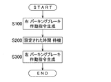
- FIG. 3 is a flowchart showing an example of shifting the time for operating the left and right parking brake mechanisms in this brake device.
- This control flow is executed when the parking brake request switch 13 is pressed and a parking brake operation request is transmitted to the parking brake operation determination device 12 (START).
- the determination of the parking brake operation failure, the time-over process at the time of waiting for the condition matching, and the like are omitted, and these are performed as necessary.
- the operation timing of the left and right parking brake mechanisms 1L and 1R is continuously operated in the left-right order, for the sake of explanation, it is described that the operation is performed in the order of the right first and the left rear. You may make it operate.
- the parking brake operation determination unit 12 first generates a parking brake operation command for the right parking brake mechanism 1R and operates the right parking brake mechanism 1R. (Step S100). Thereafter, the set time observation means 14 waits for a set fixed time (step S200). The operation command waiting unit 15 in the parking brake operation determination unit 12 determines that the parking brake operation is applied to the left parking brake mechanism 1L when the predetermined time has elapsed, that is, when it is determined that the set time observation unit 14 has set. A command is generated and the left parking brake mechanism 1L is operated (step S300). Thereafter, this process is terminated (END).
- the parking brake operation determination unit 12 in this case includes an operation completion signal monitoring unit 16 and an operation command sequential input unit 17.
- the operation completion signal monitoring means 16 inputs a parking brake operation command to either one of the left and right parking brake mechanisms 1L, 1R, and the one parking brake mechanism 1L, The presence or absence of an operation completion signal indicating that the operation of (1R) has been completed is monitored.
- a specific example of the timing at which the operation completion signal of the parking brake mechanism 1L, (1R) is output is based on the fact that the drive source 4 such as the above-described electric motor or actuator is operated by a necessary amount.
- a current sensor Sa for detecting the current of the drive source 4 is provided, and the operation completion signal monitoring means 16 uses, for example, an LUT (Look Up Table), a predetermined comparison function or conversion function of a library, etc.
- LUT Look Up Table
- the threshold is determined, for example, by a result of experiment or simulation.
- the operation command sequential input unit 17 applies to the other parking brake mechanism 1R, (1L) of the left and right parking brake mechanisms 1L, 1R. Then, a parking brake operation command is input to operate the other parking brake mechanism 1R, (1L). In this way, the left and right parking brake mechanisms 1L and 1R are continuously operated in the left-right order using the parking brake operation completion signal.
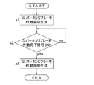
- FIG. 4 is a flowchart showing an example of using a parking brake operation completion signal in this brake device. This process starts when the parking brake request switch 13 is pressed and a parking brake operation request is transmitted to the parking brake operation determination device 12 (START). Similarly, when the parking brake operation request is input, the parking brake operation determination unit 12 first generates a parking brake operation command to the right parking brake mechanism 1R and outputs the right parking brake mechanism. 1R is operated (step a1).
- step a2 the operation completion signal monitoring means 16 stands by until a parking brake operation completion signal is received from the right parking brake mechanism 1R (step a2).
- step a2 no
- the process returns to step a2.
- step a3 the operation command sequential input means 17 generates a parking brake operation command for the left parking brake mechanism 1L, and operates the left parking brake mechanism 1L.
- the control device 2 when the parking brake request switch 13 is pressed, the control device 2 switches the left and right parking brake mechanisms 1L and 1R from the unlocked state to the parking locked state, respectively. At this time, the parking brake operation determination unit 12 in the control device 2 adjusts the timing for operating the left and right parking brake mechanisms 1L and 1R. For example, by performing processing such as rewriting the control flow of the control device 2, it is possible to reduce discomfort and discomfort due to the operating sound, and therefore, the configuration and arrangement of the components are limited as in the prior art. There is nothing. For this reason, the versatility of a brake device can be improved.
- the sound pressure level of the operating sound is carefully determined, and the left and right parking brake mechanisms 1L and 1R are operated simultaneously at the left and right or sequentially in accordance with the operating sound, thereby causing a sense of incongruity due to the operating sound. And discomfort can be reduced. For example, if the sound pressure level of the operating sound is low, the sound pressure level can be kept low even if the left and right parking brake mechanisms 1L and 1R are operated simultaneously on the left and right sides, and the generation time of the operating sound is shortened. And discomfort can be reduced.
- the vehicle configuration can be expected to have a sound shielding effect or a vibration suppression effect that is the basis of the operation sound, the sound pressure level that can be heard by the vehicle occupant even if the operation sound or the amplitude of the vibration increases is reduced. Since it can be kept low, the left and right parking brake mechanisms 1L, 1R are operated simultaneously on the left and right sides to shorten the operation sound and vibration generation time, and reduce discomfort and discomfort, as in the above example.
- the left and right parking brake mechanisms 1L and 1R are successively operated in order, so that the peak of the sound pressure level can be suppressed low, and uncomfortable and uncomfortable feeling can be reduced.
- the left and right parking brake mechanisms 1L and 1R are sequentially operated in order to suppress the operating sound and the amplitude of the vibration, thereby suppressing the peak of the sound pressure level and reducing discomfort and discomfort.
- the left and right parking brake mechanisms 1L and 1R including the drive source 4 such as an electric motor may be directly provided on the left and right service brakes 6 and 6, respectively.
- the entire brake device can be made compact, and the ease of assembly to the vehicle can be improved as compared with the first embodiment.
- the driving source 4 of each parking brake mechanism 1L, 1R for example, a direct acting actuator or an electric motor is used, and the brake shoe lever or the cam is directly driven without using a worm gear mechanism and a wire. good.
- the parking brake operation determination device 12 feels uncomfortable giving the vehicle occupant the timing to operate the left and right parking brake mechanisms 1L and 1R and the timing to operate the set mechanism in the vehicle. It is good also as what adjusts so that it may reduce.
- An example of the set mechanism is a door lock mechanism (not shown). When the door lock mechanism is also released when the parking brake is operated, an operation sound is generated even when the door lock mechanism is released. Therefore, the timing for operating the door lock mechanism and the timing for operating the parking brake mechanisms 1L and 1R. By adjusting the above, discomfort and discomfort due to the parking brake operation can be reduced.
- this electric brake device controls the left and right electric brake mechanisms 101L and 101R, the left and right parking brake mechanisms 102L and 102R, and the electric brake mechanisms 101L and 101R and the parking brake mechanisms 102L and 102R.
- a brake device having a control device 103 also referred to as an electric brake and parking brake control device 103.
- the left and right electric brake mechanisms 101L and 101R apply braking force to the left and right wheels 5 and 5 (FIG. 9) of the vehicle independently by operating the brake pedal 104, which is the brake operating means 104.
- the brake operation means 104 is not limited to a pedal input type as long as it is a means for an operator to instruct braking, and may be a button input type, a lever input type, or the like.
- the left and right electric brake mechanisms 101L and 101R are configured to be bilaterally symmetrical or have the same structure, and the left and right parking brake mechanisms 102L and 102R are also configured to be bilaterally symmetrical or have the same structure. However, for example, modifications necessary for mounting on a vehicle are allowed.
- One parking brake mechanism 102L, (102R) is assembled in association with one electric brake mechanism 101L, (101R).
- the left and right electric brake mechanisms 101L and 101R are provided on the front and rear wheels, while the left and right parking brake mechanisms 102L and 102R are provided only on either the rear wheel side or the front wheel side of the vehicle. However, the left and right parking brake mechanisms 102L and 102R may be provided for both the front and rear wheels.
- the electric brake mechanisms 101L and 101R each include an electric motor 106, a speed reduction mechanism 107 that decelerates the rotation of the electric motor 106, a linear motion mechanism 108, a brake rotor 109, and a friction pad 110.
- the electric motor 106, the speed reduction mechanism 107, and the linear motion mechanism 108 are incorporated in, for example, a housing (not shown).
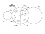
- the reduction mechanism 107 is a mechanism that reduces and transmits the rotation of the electric motor 106 to the tertiary gear 112 fixed to the rotation shaft 111, and includes a primary gear 113, an intermediate gear 114, and a tertiary gear 112.
- the speed reduction mechanism 107 decelerates the rotation of the primary gear 113 attached to the rotor shaft 106a of the electric motor 106 by a two-stage intermediate gear 114 in which two gears having different numbers of teeth are integrated.
- transmission to the tertiary gear 112 fixed to the end of the rotating shaft 111 is possible.
- the linear motion mechanism 108 converts the rotational motion output from the speed reduction mechanism 107 into a linear motion of the linear motion portion 115 having, for example, a substantially cylindrical shape or a columnar shape by a feed screw mechanism, and applies friction pads to the brake rotor 109 This is a mechanism for abutting or separating 110.
- the linearly moving portion 115 is supported so as to be free of rotation and movable in the axial direction indicated by the arrow A1.
- a friction pad 110 is provided on the outboard side (left or right side of the vehicle) end of the linear motion unit 115.
- the parking brake mechanisms 102L and (102R) can be switched between a parking lock state in which the braking force of the electric brake mechanisms 101L and (101R) is prevented from loosening and an unlocked state in which the braking force is allowed to loosen. Has been.
- the parking brake mechanisms 102L, (102R) include a lock member 116 and an actuator 117 that switches and drives the lock member 116.
- FIG. 7A is a schematic view of the main part of the parking brake mechanism as seen in plan view
- FIG. 7B is an enlarged cross-section of the locking hole 118 in FIG. 7A cut along the circumferential direction and viewed from the outboard side.
- FIG. 7A a plurality (six in this example) of locking holes 118 are formed at regular intervals in the circumferential direction on the end face of the intermediate gear 114 on the outboard side.
- Each locking hole 118 is formed in a long hole shape extending along the circumferential direction.
- the lock member 116 is configured to be able to be locked in any one of the locking holes 118.
- Each locking hole 118 has a bottomed cylindrical hole portion 118a having a flat bottom portion and an inclined hole portion 118b connected to the bottomed cylindrical hole portion 118a.
- the inclined hole portion 118b is formed in a cross-sectional shape that is inclined so as to reach the outboard side as it is separated from the portion connected to the bottomed cylindrical hole portion 118a in the circumferential direction.
- a linear solenoid is applied as the actuator 117.
- the actuator 117 moves the lock member (solenoid pin) 116 from the inside of the actuator 117 and fits into the bottomed cylindrical hole 118 a of the locking hole 118 formed in the intermediate gear 114.
- the parking lock state is established.
- a part or all of the lock member 116 is retracted into the actuator 117 and is detached from the locking hole 118, whereby the rotation of the intermediate gear 114 is allowed and the unlocked state is achieved.
- the parking brake mechanism is activated by generating a pressing force larger than the required pressing force required from the braking force required for stopping by the electric brake mechanisms 101L, 101R (FIG. 6), and then operating the actuator 117 to lock the locking member. 116 is advanced from the inside of the actuator 117 as described above. However, at this time, there is no guarantee that the locking member 116 is locked in any one of the plurality of locking holes 118 opened in the intermediate gear 114. However, even when the lock member 116 is not locked in the bottomed cylindrical hole 118a of the lock hole 118, the lock member 116 is fitted into the lock hole 118 and locked as follows.
- FIG. 8A is a diagram schematically showing the electric brake device when parking is not locked
- FIG. 8B is a diagram schematically showing the parking lock state of the electric brake device. From the state shown in FIG. 8A, after the actuator 117 is operated to move the lock member 116 to contact the intermediate gear 114 and then the rotational drive of the electric motor 106 is stopped, the friction pad 110 causes the reaction force from the brake rotor 109 to react. The linear motion part 115 of the linear motion mechanism 108 is pushed back to the inboard side.
- This reaction force causes the gears 112, 114, 113 to rotate in the pressure reducing direction. Even if the lock member 116 is advanced at the phase of the intermediate gear 114 where there is no locking hole 118, that is, the circumferential position or the inclined hole 118b, the gear 114 rotates in the pressure reducing direction. The tip of the locking member 116 slides along the inclined hole 118b (FIG. 7B) while being pushed out, and finally the position of the locking member 116 and the bottomed cylindrical hole 118a of the locking hole 118 (FIG. 7B). The phase (position) matches (FIG. 8B). Even if the intermediate gear 114 further rotates in the pressure reducing direction, as shown in FIGS. 7A and 7B, the side surface of the lock member 116 is pressed against the circumferential end 118aa of the bottomed cylindrical hole portion 118a. Further rotation of 114 is prevented.
- the rotation of the intermediate gear 114 caused by the pushing back of the linear motion portion 115 by the reaction force causes the position of the lock member 116 and the phase of the locking hole 118 to match, and the lock member 116 is in the bottomed cylindrical hole portion 118a.
- the necessary pressing force is prevented from decreasing.
- FIG. 9 is a block diagram of a control system for explaining a normal service brake operation and the like of the electric brake device.
- the control device 103 of this electric brake device has basic control means 103a.
- the control device 103 is configured by a computer having a processor, a ROM (Read Only Memory) having a program executed by the processor, and other electronic circuits such as a RAM (Random Access Memory) and a coprocessor (Co-Processor).
- the basic control means 103a operates the electric motors 106 of the left and right electric brake mechanisms 101L and 101R by operating the brake operation means 104 by the driver, and presses the friction pad 110 against the brake rotor 109 to give a braking force.
- FIG. 10 is a block diagram of the control system of this electric brake device, and the brake operation means 104 and the basic control means 103a are omitted from FIG. 9 for easy understanding.
- the control device 103 of this electric brake device includes a parking brake operation determination device 119 and left and right brake press generators 120L and 120R.
- the parking brake request switch 121 provided on the console panel of the vehicle is operated.
- the parking brake operation request generated thereby is input to the parking brake operation determination unit 119.
- the parking brake operation determination unit 119 of this example generates left and right brake press request signals to the left and right brake press generators 120L and 120R, respectively.
- the left and right brake press generators 120L and 120R output left and right brake press commands in response to left and right brake press requests.
- the left and right brake pressing commands are switched to the set pressing force. These left and right brake pressing commands are input to the left and right electric brake mechanisms 101L and 101R, respectively.
- the left and right electric brake mechanisms 101L and 101R drive the electric motor 106 according to the left and right brake pressing commands to generate a pressing force of the friction pad 110.
- the parking brake operation determination device 119 detects the feedback value of the left and right pressing forces. For example, the relationship between the pressing force and the electric motor 106 current is recorded in a relationship setting unit (not shown).
- a current sensor Sa that detects the current of the electric motor 106 is provided, and the parking brake operation determination unit 119 converts the current detected by the current sensor Sa into, for example, a predetermined comparison function or conversion function of a LUT (Look Up Table) or a library.
- the feedback value of the left and right pressing force can be calculated by applying to the relationship setting means.
- Each electric brake mechanism 101L, 101R is provided with a load sensor (not shown) such as a strain sensor that detects a reaction force from the brake rotor 109, and the parking brake operation determination unit 119 is in direct proportion to the pressing force.
- a feedback value may be obtained by detecting a detection value of each of the load sensors in the relationship.
- the parking brake operation determination unit 119 compares a pressing force required when the parking brake is set in advance (referred to as a pressing force threshold) and feedback values of the left and right pressing forces.
- a pressing force threshold a pressing force required when the parking brake is set in advance
- the parking brake operation determining unit 119 determines that the feedback values of both the left and right pressing forces exceed the pressing force threshold value
- the parking brake operation determining unit 119 generates parking brake operation commands for the left and right parking brake mechanisms 102L and 102R, respectively.
- processing such as rewriting the control flow of the control device 103, it is possible to reduce discomfort and discomfort caused by the operating sound, so that the configuration and arrangement of the electric motor and the speed reduction mechanism as in the prior art Is not limited. For this reason, the versatility of the electric brake device can be improved.
- FIG. 11 is a flowchart showing a process in which the control device of the electric brake device makes a left and right brake pressing request at the same time, and the left and right parking brake mechanisms are operated simultaneously at the left and right or sequentially in the left and right order.
- the operation timings of the left and right parking brake mechanisms may be the same on the left and right, or may be made sequentially in the left-right order.
- the left and right brake press requests are signals input from the parking brake operation determination unit 119 to the left and right brake press generators 120L and 120R.
- the left and right brake press generators 120L and 120R receive the left and right brake press requests, and output the brake press commands to the left and right electric brake mechanisms 101L and 101R, respectively, to generate the set pressing force. .
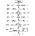
- This process is started by operating the parking brake request switch 121 (START), and when the parking brake operation request is input, the parking brake operation determination unit 119 generates left and right brake pressing requests (step S1). .
- the left and right brake press generators 120L and 120R change the output of the left and right brake press commands from the press command zero (a press command indicating zero press), which is necessary for parking braking. Switch to command.
- the left and right brake pressing commands are input to the left and right electric brake mechanisms 101L and 101R, respectively.
- the left and right electric brake mechanisms 101L and 101R generate a pressing force in accordance with the left and right brake pressing commands.
- the left and right pressing forces are output as left and right pressing feedback values from the left and right electric brake mechanisms 101L and 101R, respectively.
- the parking brake operation determination unit 119 applies the current detected by the current sensor Sa to the relationship setting unit to obtain left and right pressing feedback values (step S2).
- the parking brake operation determination unit 119 compares the pressing force threshold value with the left and right pressing feedback values (step S3).
- the parking brake operation determining unit 119 determines parking brake operation commands for the left and right parking brake mechanisms 102L and 102R, respectively. It is generated at the given timing (step S4).
- the predetermined timing is, for example, a command generation timing that can suppress a sound pressure level that can be heard by a vehicle occupant from a test result and reduce a sense of discomfort and discomfort of the occupant.
- step S3 when the parking brake operation determination device 119 determines that the feedback value of the pressing force does not exceed the pressing force threshold value in either the left or right (step S3: no), the process returns to step S2, and the parking brake operation determination device. 119 again detects the feedback values of the left and right pressing forces, and waits for both feedback values to exceed the pressing force threshold.
- step S3 description of processing such as error processing described above is omitted when conditions for a certain time cannot be satisfied, but error processing or the like is added as necessary.
- step S4 when the parking brake operation command is generated simultaneously on the left and right, the parking brake operation command is generated for the left and right parking brake mechanisms 102L and 102R when executing step S4.
- FIG. 12 shows a process when the parking brake operation command is continuously generated in the left-right order in step S4.
- the parking brake operation determination unit 119 first generates a parking brake operation command for the right parking brake mechanism 102R (step S4-1).
- the parking brake operation determination unit 119 waits for a time set in order to realize a timing for reducing discomfort and discomfort (step S4-2).
- step S4-3 This set time is set, for example, based on results of experiments and simulations.
- the parking brake operation determination unit 119 generates a parking brake operation command for the left parking brake mechanism 102L (step S4-3). Thereafter, this process is terminated (END).
- the other steps S1 to S3 are the same as in FIG.
- the following example in which steps S1 to S3 are omitted is the same as in FIG.
- the parking brake operation determination unit 119 outputs a parking brake operation completion signal to check whether or not the lock member 116 of the parking brake mechanisms 102L and 102R is locked in the locking hole 118. It may be used as a condition for proceeding to the next control step.
- the parking brake operation completion signal is a signal based on, for example, that one or both of the electric motor 106 and the actuator 117 are operated as necessary.
- step S4 in FIG. 11 is replaced with step S4-6 from step S4-4 in FIG. That is, as shown in FIG. 13, the parking brake operation determination unit 119 first generates a parking brake operation command to the right parking brake mechanism 102R (step S4-4), and the parking brake operation 102R of the right parking brake mechanism 102R is parked. Wait until a brake operation completion signal is obtained (step S4-5). When the parking brake operation determining unit 119 confirms the parking brake operation completion signal (step S4-5: yes), it generates a parking brake operation command for the remaining left parking brake mechanism 102L (step S4-6).
- the parking brake operation determination unit 119 When the parking brake operation request is transmitted, the parking brake operation determination unit 119 generates a right brake pressing request (step S5). In response to this right brake press request, the right brake press generator 120R switches the right brake press command from the zero press command to a preset press command necessary for parking braking.
- the right brake pressing command is input to the right electric brake mechanism 101R, and the right electric brake mechanism 101R generates a pressing force according to the right brake pressing command.
- the pressing force at this time is output as a right pressing feedback value, and the parking brake operation determination unit 119 detects the right pressing feedback value (step S6).
- the parking brake operation determination unit 119 compares the pressing force threshold value with the right pressing feedback value (step S7).
- step S7 When it is determined that the right pressing feedback value is equal to or less than the pressing force threshold (step S7: no), the process returns to step S6.
- the parking brake operation determining unit 119 confirms that the right pressing feedback value exceeds the pressing force threshold value (step S7: yes)
- the parking brake operation determining unit 119 generates a left brake pressing request (step S8).
- the left brake pressure generator 120L switches the left brake pressure command from a zero pressure command to a preset pressure command necessary for parking braking.
- the left electric brake mechanism 101L generates a pressing force in accordance with the left brake pressing command.
- the parking brake operation determination unit 119 detects the left pressing feedback value output from the left electric brake mechanism 101L (step S9). Next, the parking brake operation determination unit 119 compares the pressing force threshold value with the left pressing feedback value (step S10). If it is determined that the left pressing feedback value is equal to or less than the pressing force threshold value (step S10: no), the process returns to step S9.
- step S10 When the parking brake operation determining unit 119 confirms that the left pressing feedback value has exceeded the pressing force threshold (step S10: yes), the parking brake operation determining unit 119 performs parking to the left and right parking brake mechanisms 102L and 102R.
- a brake operation command is generated at a predetermined timing (step S11). At this time, the timing for generating the left and right parking brake operation commands is set as the command generation timing for reducing the above-mentioned uncomfortable feeling and discomfort. Thereafter, this process is terminated (END).
- step S11 when the parking brake operation command is generated at the same time on the left and right, the parking brake operation determining unit 119 performs parking for the left and right parking brake mechanisms 102L and 102R when executing step S11, as in step S4. Generate a brake activation command.
- steps S4-1 to S4-3 shown in FIG. 12 are similarly performed in step S11.
- step S11 is performed in step S4- in FIG. Replace 4 with step S4-6.
- FIG. 15 is a block diagram of a control system of the electric brake device according to the modification of the third embodiment.
- the electric brake device control device 103A includes a parking brake operation determination unit 119 and left and right electric brake and parking brake control devices 122L and 122R.
- Brake pressure generators 120L and 120R are provided in the electric brake and parking brake control devices 122L and 122R, respectively, and a parking brake operation determination unit 119 is provided outside the electric brake and parking brake control devices 122L and 122R.
- the parking brake operation determination device 119 has been handled on the assumption that it exists inside the electric brake and parking brake control device.
- the parking brake operation determining unit 119 is inside or outside the electric brake and parking brake control device.
- the parking brake operation determination device 119 is not necessarily provided either inside or outside.
- the parking brake operation determination unit 119 is replaced with the electric brake and parking brake control device 122L, It is more appropriate to provide it outside of 122R.
- the reason is that an element for simultaneously monitoring the states of the left and right electric brake mechanisms 101L and 101R and the parking brake mechanisms 102L and 102R is necessary. This is because it is more practical to provide the determination unit 119 because a simple configuration can be taken.
- the parking brake operation determination device is provided inside the electric brake and parking brake control device, either the left or right electric brake and parking brake control device are monitored simultaneously as described above, or the left and right electric brakes are And the parking brake control device communicate with each other to monitor the pressure feedback value, adjust each operation timing, or either one of the left and right has the priority represented by the master slave, and the pressure feedback value by communication It is necessary to determine the timing of each operation. Therefore, by adopting this configuration, the control and configuration become complicated, and there is no advantage from the viewpoint of reducing discomfort and discomfort due to the operating sound.
- the control flow can be controlled as described above.
- the parking brake operation command and the information on the feedback value of the pressing force are transmitted to the parking brake mechanisms 102L and 102R and the electric brake mechanisms 101L and 101R via the electric brake and parking brake control devices 122L and 122R. Exchanged with the brake operation determination device 119.
- each of the electric brake and parking brake control devices 122L and 122R, and an integrated controller (not shown) of the higher-level vehicle and the parking brake operation determination unit 119 are respectively connected by mutual communication means such as CAN bus communication. It is realistic to connect and send and receive necessary information in a batch. Therefore, there is no additional signal line due to an increase in the number of information.
- the parking brake operation command and the feedback value of the pressing force are directly exchanged with the parking brake operation determination unit 119, the electric brake mechanisms 101L and 101R, and the parking brake mechanisms 102L and 102R without using the electric brake and parking brake control devices 122L and 122R.
- the electric brake and parking brake control device includes a parking brake operation determination unit 119 and a brake press generator 120 (for the right brake in the illustrated example). And a brake pedal pressing command generator 124 and a pressing command adder 123. Based on the brake pedal pressing request input by the brake pedal 104, the brake pedal pressing command generator 124 generates a brake pedal pressing command. This brake pedal pressing command is input to the pressing command adder 123.
- the parking brake operation determination unit 119 receives the parking brake operation request and generates a brake pressing request (for the right brake in the example in the figure) at a predetermined timing.
- the brake press generator 120 inputs a necessary press command (referred to as a parking brake press command) to the press command adder 123.
- the press command adder 123 the two press commands are added and output as the entire press command.
- a press command selector may be used instead of the press command adder 123.
- the press command selector can be replaced with the press command adder 123, and selects a larger one of the two input press commands and outputs it as the entire press command.
- the press command adder 123 when the parking brake mechanism is used, for example, even when the vehicle is likely to undesirably move backward on a slope, if the brake pedal is depressed, the braking force immediately increases and the vehicle moves backward. Can be prevented. However, if the pressing force generated during parking brake is large, there is a high possibility that the brake will be locked.
- the control flow is almost the same as in FIG. What is changed in the signal flow is a portion related to the brake pressing command generator 120.
- a parking brake operation request is directly input to the brake press generator 120, and the parking brake press command is immediately set to a predetermined press required for parking brake from zero to right. Each is switched to a command.
- the processing after step S1 in FIG. 11 is the same as when the control flow in FIG. 11 is executed using the control block in FIG.
- the command timing for parking brake operation should be taken into account. You may decide.
- a door lock can be considered. When the parking brake is operated in a state where an occupant is on the vehicle, it is more convenient for the occupant to release the door lock.
- the left and right wheels that independently apply braking force to the left and right wheels in the vehicle and maintain the vehicle in a stopped state.
- a parking brake operation determination device that adjusts the mutual timing for operating the left and right brake mechanisms to reduce the uncomfortable feeling given to the vehicle occupant
- the left and right electric brake mechanisms that can independently add braking force to the left and right wheels in the vehicle and are operated by a brake operation means by the driver;
- Left and right parking brake mechanisms that can be switched independently between left and right parking lock states that prevent the braking force of the left and right electric brake mechanisms from loosening and unlock states that allow the braking force to loosen;
- a control device for controlling the electric brake mechanism and the parking brake mechanism;
Abstract
Provided is a brake device capable of improving device versatility and reducing an incongruous feeling caused by the operation sound of a parking brake. The brake device includes left and right parking brake mechanisms (1L, 1R) that separately apply a braking force to left and right wheels of a vehicle and maintain the vehicle in a stopped state, and a control device (2) that controls the parking brake mechanisms (1L, 1R). The control device (2) is provided with a parking brake operation determination device (12) that adjusts the mutual timings at which the left and right parking brake mechanisms (1L, 1R) are caused to operate so as to reduce an incongruous feeling experienced by a passenger of the vehicle.
Description
本出願は、2014年4月22日出願の特願2014-88477、および2014年4月22日出願の特願2014-88478の優先権を主張するものであり、その全体を参照により本願の一部をなすものとして引用する。
This application claims the priority of Japanese Patent Application No. 2014-88477 filed on April 22, 2014 and Japanese Patent Application No. 2014-88478 filed on April 22, 2014, which is incorporated herein by reference in its entirety. Quote as part.
この発明は、左右が独立した機構を有するブレーキ装置に関し、パーキングブレーキ作動時の作動音を低減する技術に関する。
This invention relates to a brake device having a left and right independent mechanism, and relates to a technique for reducing operating noise when a parking brake is operated.
電動モータを駆動源として制動力を発生させ、前記電動モータへの通電を停止後も前記制動力を維持し得るブレーキ装置が提案されている。このブレーキ装置を搭載する車両において、パーキングブレーキの作動時に少なからず作動音が発生してしまい、この作動音による違和感や不快感が発生していた。作動音の具体例としては、例えば、押圧発生機構に取り付けられたラチェットから発する音や、ロック機構の締結時の音、また制動力を発生させる押圧上昇時の音が挙げられ、これらによる違和感や不快感の低減が必要とされていた。
Brake devices have been proposed that can generate a braking force using an electric motor as a drive source and maintain the braking force even after energization of the electric motor is stopped. In a vehicle equipped with this brake device, not a little operation noise is generated when the parking brake is operated, and there is a sense of incongruity or discomfort due to this operation sound. Specific examples of the operating sound include, for example, a sound emitted from a ratchet attached to the press generation mechanism, a sound at the time of fastening the lock mechanism, and a sound at the time of pressure increase that generates a braking force. There was a need to reduce discomfort.
パーキングブレーキの作動時の作動音が原因となる違和感や不快感を低減する方法として、作動音の音圧レベルを低く抑えるための施策を採ることと、同じ音が発生しても違和感や不快感を発生しにくいように工夫することが挙げられる。前者の方法については、電動パーキングブレーキ付き電動ブレーキ装置について、モータや減速機の構成と配置を最適にすることにより、作動音を低減する方法が示されている(特許文献1)。また電動パーキング装置において、モータ出力軸をロックする際の衝撃が作動音となっていたため、ロック機構の係合部凸部もしくは凹部に弾性部を設けて、作動音を抑制する方法が示されている(特許文献2)。
Measures to reduce the sound pressure level of the operating sound as a method of reducing the uncomfortable feeling and discomfort caused by the operating sound when the parking brake is activated, and the discomfort and uncomfortable feeling even if the same sound is generated It is possible to devise so that it is difficult to generate. As for the former method, a method of reducing operating noise by optimizing the configuration and arrangement of a motor and a speed reducer for an electric brake device with an electric parking brake is disclosed (Patent Document 1). Also, in the electric parking device, since the impact when locking the motor output shaft was the operating noise, a method for suppressing the operating noise by providing an elastic part on the engaging part convex part or concave part of the locking mechanism is shown. (Patent Document 2).
後者の方法については、パーキングブレーキ作動開始から終了までの間、車両の搭乗者の注意を喚起する電子音を発生して、ブレーキ作動を報知するのと同時に、報知することによって作動音が発生してもパーキングブレーキの作動による正常な現象であることを印象づけて安心感を与え、電子音によって作動音自体も気付きにくくする方法が示されている(特許文献3)。
In the latter method, an electronic sound is generated from the start to the end of parking brake operation to alert the vehicle occupant and the brake operation is notified at the same time. However, there is a method of giving a sense of security by impressing that this is a normal phenomenon caused by the operation of the parking brake, and making the operation sound itself difficult to notice with an electronic sound (Patent Document 3).
前記モータや減速機の構成と配置を最適にする特許文献1の技術では、モータおよび減速機の構成と配置が制限され、パーキングブレーキ付き電動ブレーキ装置の汎用性が低下する問題がある。前記ロック機構に弾性部を設ける特許文献2の技術では、装置構造が複雑化して製造コストが高くなる。同技術において、電動モータの回転を減速する減速機の歯打ち音や、ロック機構のアクチュエータの作動音等に作動音の原因がある場合には、作動音を抑制することができない。
In the technique of Patent Document 1 that optimizes the configuration and arrangement of the motor and the reduction gear, there is a problem that the configuration and arrangement of the motor and the reduction gear are limited, and the versatility of the electric brake device with a parking brake is lowered. In the technique of Patent Document 2 in which the lock mechanism is provided with an elastic portion, the structure of the apparatus becomes complicated and the manufacturing cost increases. In the same technology, when there is a cause of the operation noise in the rattling sound of the speed reducer that decelerates the rotation of the electric motor or the operation sound of the actuator of the lock mechanism, the operation noise cannot be suppressed.
前記電子音を発生する特許文献3の技術では、例えば、電子音の大きさや周波数帯等によっては、パーキングブレーキの作動時の作動音を適切に抑制できない場合があることに加え、電子音自体が作動音の原因となる場合が考えられる。これらの作動音に起因して運転者等に違和感や不快感を与えてしまう。
In the technique of Patent Document 3 that generates the electronic sound, for example, depending on the size or frequency band of the electronic sound, the operating sound when the parking brake is operated may not be appropriately suppressed. It may be the cause of operating noise. Due to these operating sounds, the driver or the like is uncomfortable or uncomfortable.
この発明の目的は、装置の汎用性の向上を図ることができ、またパーキングブレーキの作動音に起因した違和感および不快感を低減することができるブレーキ装置を提供することである。
An object of the present invention is to provide a brake device that can improve the versatility of the device and can reduce discomfort and discomfort caused by the operating sound of a parking brake.
以下、この発明について、理解を容易にするために、便宜上実施形態の符号を参照して説明する。
Hereinafter, in order to facilitate understanding, the present invention will be described with reference to the reference numerals of the embodiments for convenience.
この発明のブレーキ装置は、車両における左右の車輪に対してそれぞれ独立して制動力を付加し、且つ、前記車両を停車状態に維持する左右のパーキングブレーキ機構1L,1Rと、これらパーキングブレーキ機構1L,1Rを制御する制御装置2とを備えたブレーキ装置であって、
前記左右のパーキングブレーキ機構1L,1Rを作動させる相互のタイミングを前記車両の乗員に与える違和感を低減させるように調整するパーキングブレーキ作動判断器12を、前記制御装置2に設ける。 The brake device according to the present invention applies left and right parking brake mechanisms 1L and 1R that independently apply braking force to the left and right wheels of the vehicle and maintains the vehicle in a stopped state, and these parking brake mechanisms 1L. , 1R, and a braking device including a control device 2 for controlling 1R,
Thecontrol device 2 is provided with a parking brake operation determination device 12 for adjusting the mutual timing for operating the left and right parking brake mechanisms 1L and 1R so as to reduce the uncomfortable feeling given to the vehicle occupant.
前記左右のパーキングブレーキ機構1L,1Rを作動させる相互のタイミングを前記車両の乗員に与える違和感を低減させるように調整するパーキングブレーキ作動判断器12を、前記制御装置2に設ける。 The brake device according to the present invention applies left and right
The
パーキングブレーキの作動音による違和感や不快感を低減する方法として、様々な面から複合的に施策を実施することにより、全体としてより高い静粛性を得ることができる。先に示したこれまでの機構面による作動音の音圧レベルの抑制と電子音による違和感や不快感の低減以外に、本件出願人は、作動指令の生成タイミングの最適化等、制御に関する施策によって、違和感や不快感の低減を実施する余地があることを見出した。
As a method of reducing discomfort and discomfort due to the operating sound of the parking brake, it is possible to obtain higher overall quietness by implementing multiple measures from various aspects. In addition to the suppression of the sound pressure level of the operating sound and the reduction of discomfort and discomfort caused by the electronic sound as described above, the Applicant has applied control measures such as optimizing the generation timing of the operation command. They found that there was room to reduce discomfort and discomfort.
左右の車輪に対してそれぞれ独立して制動力を付加する左右のパーキングブレーキ機構の場合、作動タイミングも独立して決定することができる。そこでパーキングブレーキ作動時の作動音の中で、最も違和感や不快感を発生する可能性の高い作動音(以下、単に「作動音」と呼ぶ。)に着目し、例えば、作動指令の生成タイミングを制御することにより、作動音の発生タイミングを管理して、同じ作動音が発生していても運転者等に与える違和感や不快感を低減しうる。よって、パーキングブレーキの作動音に起因した違和感および不快感を低減することができる。
In the case of the left and right parking brake mechanisms that apply braking force independently to the left and right wheels, the operation timing can also be determined independently. Therefore, focusing on the operation sound (hereinafter simply referred to as “operation sound”) that is most likely to cause discomfort and discomfort among the operation sounds when the parking brake is operated, for example, the generation timing of the operation command is By controlling, it is possible to manage the generation timing of the operation sound, and to reduce discomfort and discomfort given to the driver or the like even if the same operation sound is generated. Therefore, the uncomfortable feeling and discomfort caused by the operating sound of the parking brake can be reduced.
この構成によると、運転者が、例えば、パーキングブレーキ要求スイッチ13等を操作すると、制御装置2は、左右のパーキングブレーキ機構1L,1Rをそれぞれアンロック状態からパーキングロック状態に切換える。このとき、制御装置2におけるパーキングブレーキ作動判断器12は、左右のパーキングブレーキ機構1L,1Rを作動させるタイミングを調整する。例えば、制御装置2の制御フローを書き換える等の処理を行うことにより、作動音に起因する違和感および不快感を低減させることができるため、従来技術のように構成部品の構成と配置が制限されることはない。このため、ブレーキ装置の汎用性の向上を図ることができる。
According to this configuration, when the driver operates, for example, the parking brake request switch 13 or the like, the control device 2 switches the left and right parking brake mechanisms 1L and 1R from the unlocked state to the parking locked state, respectively. At this time, the parking brake operation determination unit 12 in the control device 2 adjusts the timing for operating the left and right parking brake mechanisms 1L and 1R. For example, by performing processing such as rewriting the control flow of the control device 2, it is possible to reduce discomfort and discomfort due to the operating sound, and therefore, the configuration and arrangement of the components are limited as in the prior art. There is nothing. For this reason, the versatility of a brake device can be improved.
違和感および不快感を低減する作動音の発生タイミングは、作動音の音圧レベルや周波数分布、パーキングブレーキ機構1L,1Rの配置や取り付け方法、車両への作動音の伝播経路や共振、びびり具合によって、車両設計時に予め設定する。
The generation timing of the operating sound that reduces discomfort and discomfort depends on the sound pressure level and frequency distribution of the operating sound, the arrangement and mounting method of the parking brake mechanisms 1L and 1R, the propagation path and resonance of the operating sound to the vehicle, and the state of chatter. It is set in advance when designing the vehicle.
例えば、作動音の音圧レベルが低ければ、左右のパーキングブレーキ機構1L,1Rを左右同時に作動させても音圧レベルを低く抑えることができ、かつ作動音の発生時間を短くすることで、違和感や不快感を低減することができる。また、車両構成により作動音の遮蔽効果や作動音のもととなる振動の制振効果が見込める場合は、作動音や振動の振幅が大きくなっても、車両の乗員に聞こえる音圧レベルを低く抑えることができることから、前記の例と同様に、左右のパーキングブレーキ機構1L,1Rを左右同時に作動させて、作動音と振動の発生時間を短くし、違和感や不快感を低減することができる。
For example, if the sound pressure level of the operating sound is low, the sound pressure level can be kept low even if the left and right parking brake mechanisms 1L and 1R are operated simultaneously on the left and right sides, and the generation time of the operating sound is shortened. And discomfort can be reduced. Also, if the vehicle configuration can be expected to have a shielding effect for operating noise and a damping effect for vibration that is the source of the operating noise, the sound pressure level that can be heard by the vehicle occupant is reduced even if the amplitude of the operating noise and vibration increases. Since it can be suppressed, the left and right parking brake mechanisms 1L and 1R can be operated simultaneously on the left and right sides to shorten the operating noise and the generation time of vibration, and to reduce discomfort and discomfort, as in the above example.
ここで作動音の発生時間とは、作動音が乗員に聞こえている時間であり、左右のパーキングブレーキ機構1L,1Rを左右同時に作動させる場合は通常動作の1倍の発生時間であり、片側のパーキングブレーキ機構1L,(1R)の作動完了直後に、逆側のパーキングブレーキ機構1R,(1L)を連続的に作動させる場合は通常動作の2倍の発生時間となる。
Here, the generation time of the operation sound is the time that the operation sound is heard by the occupant. When the left and right parking brake mechanisms 1L and 1R are operated simultaneously on the left and right, the generation time is one time of the normal operation. Immediately after the completion of the operation of the parking brake mechanism 1L, (1R), when the reverse side parking brake mechanism 1R, (1L) is continuously operated, the generation time is twice as long as the normal operation.
上記の例とは逆に作動音の音圧レベルが高ければ、左右のパーキングブレーキ機構1L,1Rを、タイミングをずらして、順に連続的に作動させることで、音圧レベルのピークを低く抑えることができ、違和感や不快感を低減することができる。また、車両構成により作動音の遮音効果や作動音のもととなる振動の制振効果が見込めない場合、具体的には空気伝播しやすい場合や、共振やびびり音(ビートノイズ)が発生しやすい場合は、作動音や振動の振幅を小さく抑えるため、左右のパーキングブレーキ機構1L,1Rを順に連続的に作動させることで、音圧レベルのピークを低く抑え、違和感や不快感を低減することができる。
Contrary to the above example, if the sound pressure level of the operating sound is high, the left and right parking brake mechanisms 1L and 1R are sequentially operated at different timings to keep the sound pressure level peak low. Can reduce discomfort and discomfort. In addition, if the sound insulation effect of the operation sound or the vibration suppression effect that causes the operation sound cannot be expected due to the vehicle configuration, specifically, the air easily propagates or resonance or chatter noise (beat noise) occurs. When it is easy, the left and right parking brake mechanisms 1L and 1R are sequentially operated in order to keep the operating sound and vibration amplitude small, thereby suppressing the peak of the sound pressure level and reducing discomfort and discomfort. Can do.
上記の例と相反するが、音圧レベルが高くても乗員が違和感や不快感を受けにくい周波数帯の作動音である場合、左右のパーキングブレーキ機構1L,1Rを同時に作動させる方が望ましい場合や、音圧レベルが非常に低く、片側のパーキングブレーキ機構1L,(1R)の動作であれば知覚できないが左右両側のパーキングブレーキ機構1L,1Rが動作すると知覚できるような作動音であれば、左右のパーキングブレーキ機構1L,1Rを連続的に作動させる方法を採ることが望ましい。このように実際には、車両設計時にパーキングブレーキ機構1L,1Rへの作動指令の生成タイミングを変更して官能調査を実施し、最も違和感や不快感の少ないタイミングを採用するのが妥当である。
Contrary to the above example, if the operating sound is in a frequency band where the passenger is not likely to feel discomfort or discomfort even if the sound pressure level is high, it is desirable to operate the left and right parking brake mechanisms 1L and 1R simultaneously. If the sound pressure level is very low and cannot be perceived if the parking brake mechanism 1L, (1R) on one side is operated, the operation sound can be perceived if the parking brake mechanisms 1L, 1R on both the left and right sides are operated. It is desirable to adopt a method of continuously operating the parking brake mechanisms 1L, 1R. As described above, in practice, it is appropriate to change the generation timing of the operation command to the parking brake mechanisms 1L and 1R at the time of vehicle design and perform a sensory survey to adopt the timing with the least discomfort and discomfort.
前記パーキングブレーキ作動判断器12は、前記車両の運転者のパーキングブレーキ作動要求が入力されると、前記車両の乗員に与える違和感を低減させるため、設定されたタイミングに基づき前記左右のパーキングブレーキ機構1L,1Rに対してパーキングブレーキ作動指令をそれぞれ入力して、前記車両を停車状態に維持するパーキングロック状態に作動させるものとしても良い。前記タイミングは、例えば、試験やシミュレーション等の結果により最も違和感や不快感の少ないタイミングが設定される。
When the parking brake operation request of the vehicle driver is input, the parking brake operation determination unit 12 reduces the uncomfortable feeling given to the occupant of the vehicle based on the set timing. , 1R, a parking brake operation command may be input to operate the vehicle in a parking lock state for maintaining the vehicle in a stopped state. For example, the timing with the least discomfort and discomfort is set according to the results of tests, simulations, and the like.
前記パーキングブレーキ作動判断器12は、
前記左右のパーキングブレーキ機構1L,1Rにおけるいずれか一方のパーキングブレーキ機構1L,(1R)に対してパーキングブレーキ作動指令を入力して、前記一方のパーキングブレーキ機構1L,(1R)の作動が完了したことを示す作動完了信号の有無を監視する作動完了信号監視手段16と、
この作動完了信号監視手段16により作動完了信号があったとき、前記左右のパーキングブレーキ機構1L,1Rにおけるいずれか他方のパーキングブレーキ機構1R,(1L)に対してパーキングブレーキ作動指令を入力する作動指令順次入力手段17とを有するものとしても良い。 The parking brakeoperation determining device 12 is
A parking brake operation command is input to one of the left and right parking brake mechanisms 1L, 1R to complete the operation of the one parking brake mechanism 1L, (1R). An operation completion signal monitoring means 16 for monitoring the presence or absence of an operation completion signal indicating that,
When there is an operation completion signal by the operation completion signal monitoring means 16, an operation command for inputting a parking brake operation command to the otherparking brake mechanism 1R, (1L) in the left and right parking brake mechanisms 1L, 1R. It is good also as what has the input means 17 sequentially.
前記左右のパーキングブレーキ機構1L,1Rにおけるいずれか一方のパーキングブレーキ機構1L,(1R)に対してパーキングブレーキ作動指令を入力して、前記一方のパーキングブレーキ機構1L,(1R)の作動が完了したことを示す作動完了信号の有無を監視する作動完了信号監視手段16と、
この作動完了信号監視手段16により作動完了信号があったとき、前記左右のパーキングブレーキ機構1L,1Rにおけるいずれか他方のパーキングブレーキ機構1R,(1L)に対してパーキングブレーキ作動指令を入力する作動指令順次入力手段17とを有するものとしても良い。 The parking brake
A parking brake operation command is input to one of the left and right
When there is an operation completion signal by the operation completion signal monitoring means 16, an operation command for inputting a parking brake operation command to the other
この場合、パーキングブレーキ作動判断器12が、一方のパーキングブレーキ機構1L,(1R)に対してパーキングブレーキ作動指令を入力すると、作動完了信号監視手段16は作動完了信号を受信するまで待機する。作動指令順次入力手段17は、前記作動完了信号を受信すると、他方のパーキングブレーキ機構1R,(1L)に対してパーキングブレーキ作動指令を入力する。このように左右のパーキングブレーキ機構1L,1Rを順に連続的に作動させることで、音圧レベルのピークを低く抑え、違和感や不快感を低減することができる。
In this case, when the parking brake operation determination device 12 inputs a parking brake operation command to one parking brake mechanism 1L, (1R), the operation completion signal monitoring means 16 stands by until receiving an operation completion signal. When receiving the operation completion signal, the operation command sequential input means 17 inputs a parking brake operation command to the other parking brake mechanism 1R, (1L). Thus, by sequentially operating the left and right parking brake mechanisms 1L and 1R in order, the peak of the sound pressure level can be suppressed low, and uncomfortable and uncomfortable feeling can be reduced.
前記パーキングブレーキ作動判断器12は、前記タイミングとして、前記左右のパーキングブレーキ機構1L,1Rを同時に作動させるものとしても良い。例えば、作動音の音圧レベルが低い場合、または、車両構成により作動音の遮蔽効果や作動音のもととなる振動の制振効果が見込める場合等は、左右のパーキングブレーキ機構1L,1Rを同時に作動させることで、作動音や振動の発生時間を短くし、車両の乗員の違和感や不快感を低減することができる。
The parking brake operation determination unit 12 may operate the left and right parking brake mechanisms 1L and 1R simultaneously as the timing. For example, when the sound pressure level of the operating sound is low, or when the effect of shielding the operating sound or the vibration suppression effect of the operating sound can be expected depending on the vehicle configuration, the left and right parking brake mechanisms 1L and 1R are installed. By operating simultaneously, the generation time of an operation sound and a vibration can be shortened, and the discomfort and discomfort of the vehicle occupant can be reduced.
前記パーキングブレーキ作動判断器12は、
前記左右のパーキングブレーキ機構1L,1Rにおけるいずれか一方のパーキングブレーキ機構1L,(1R)に対してパーキングブレーキ作動指令を入力して、設定された時間経過したか否かを判定する設定時間観測手段14と、
この設定時間観測手段14により前記設定された時間経過したと判定したとき、前記左右のパーキングブレーキ機構1L,1Rにおけるいずれか他方のパーキングブレーキ機構1R,(1L)に対してパーキングブレーキ作動指令を入力する作動指令待機手段15とを有するものとしても良い。
前記設定された時間は、例えば、車両設計時に官能評価等によって決定する。 The parking brakeoperation determining device 12 is
Setting time observation means for determining whether a set time has elapsed by inputting a parking brake operation command to one of the left and rightparking brake mechanisms 1L, 1R. 14 and
When it is determined by the set time observation means 14 that the set time has elapsed, a parking brake operation command is input to the otherparking brake mechanism 1R, (1L) of the left and right parking brake mechanisms 1L, 1R. It is good also as what has the operation command waiting means 15 to perform.
The set time is determined by sensory evaluation or the like at the time of vehicle design, for example.
前記左右のパーキングブレーキ機構1L,1Rにおけるいずれか一方のパーキングブレーキ機構1L,(1R)に対してパーキングブレーキ作動指令を入力して、設定された時間経過したか否かを判定する設定時間観測手段14と、
この設定時間観測手段14により前記設定された時間経過したと判定したとき、前記左右のパーキングブレーキ機構1L,1Rにおけるいずれか他方のパーキングブレーキ機構1R,(1L)に対してパーキングブレーキ作動指令を入力する作動指令待機手段15とを有するものとしても良い。
前記設定された時間は、例えば、車両設計時に官能評価等によって決定する。 The parking brake
Setting time observation means for determining whether a set time has elapsed by inputting a parking brake operation command to one of the left and right
When it is determined by the set time observation means 14 that the set time has elapsed, a parking brake operation command is input to the other
The set time is determined by sensory evaluation or the like at the time of vehicle design, for example.
この場合、パーキングブレーキ作動判断器12が、一方のパーキングブレーキ機構1L,(1R)に対してパーキングブレーキ作動指令を入力すると、設定時間観測手段14は、設定された時間が経過したか否かを判定する。この設定された時間が経過したと判定されると、作動指令待機手段15は、他方のパーキングブレーキ機構1R,(1L)に対してパーキングブレーキ作動指令を入力する。このように左右のパーキングブレーキ機構1L,1Rを順に連続的に作動させることで、音圧レベルのピークを低く抑え、違和感や不快感を低減することができる。
In this case, when the parking brake operation determination device 12 inputs a parking brake operation command to one parking brake mechanism 1L, (1R), the set time observation means 14 determines whether or not the set time has elapsed. judge. When it is determined that the set time has elapsed, the operation command waiting unit 15 inputs a parking brake operation command to the other parking brake mechanism 1R, (1L). Thus, by sequentially operating the left and right parking brake mechanisms 1L and 1R in order, the peak of the sound pressure level can be suppressed low, and uncomfortable and uncomfortable feeling can be reduced.
前記パーキングブレーキ作動判断器12は、前記左右のパーキングブレーキ機構1L,1Rを作動させるタイミングと、前記車両における設定された機構であって作動音が発生する設定された機構を作動させるタイミングとを前記車両の乗員に与える違和感を低減させるように調整するものとしても良い。前記設定された機構としては、例えば、ドアロック機構がある。
The parking brake operation determination unit 12 has a timing for operating the left and right parking brake mechanisms 1L and 1R and a timing for operating a set mechanism that generates a working sound in the vehicle. It is good also as what adjusts so that the discomfort given to the passenger | crew of a vehicle may be reduced. An example of the set mechanism is a door lock mechanism.
前記設定された機構がドアロック機構である場合を例とすると、違和感や不快感を低減するように左右のパーキングブレーキ機構を作動させるタイミングを決定する観点に立てば、車両のドアロック機構でも何らかの作動音が発生する場合、ドアロック機構の作動音も考慮に入れてパーキングブレーキ機構を作動させる。乗員が車両に乗車した状態でパーキングブレーキ機構を作動させる場合は、ドアロック機構を解除しておいた方が乗員にとって利便性が高い。そこで、パーキングブレーキ作動時にドアロック機構も解除するという構成にした場合、ドアロック機構の解除時にも作動音が発生するため、このドアロック機構を作動させるタイミングと、パーキングブレーキ機構1L,1Rを作動させるタイミングとを調整する(例えば、ドアロック機構の作動時にパーキングブレーキをほぼ同時に作動させる)ことで、パーキングブレーキ作動による違和感や不快感を低減することができる。
Taking the case where the set mechanism is a door lock mechanism as an example, from the viewpoint of determining the timing for operating the left and right parking brake mechanisms so as to reduce discomfort and discomfort, the vehicle door lock mechanism is When the operation sound is generated, the parking brake mechanism is operated in consideration of the operation sound of the door lock mechanism. When the parking brake mechanism is operated while the occupant is in the vehicle, it is more convenient for the occupant to release the door lock mechanism. Therefore, when the door lock mechanism is also released when the parking brake is operated, an operation sound is generated even when the door lock mechanism is released. Therefore, the timing for operating the door lock mechanism and the parking brake mechanisms 1L and 1R are operated. By adjusting the timing (for example, operating the parking brake almost simultaneously when the door lock mechanism is operated), it is possible to reduce discomfort and discomfort due to the parking brake operation.
この発明のブレーキ装置において、好ましくは、前記車両における左右の車輪5,5に対してそれぞれ独立して制動力を付加可能であり、運転者によるブレーキ操作手段104により操作される左右の電動ブレーキ機構101L,101Rを備え、
前記左右のパーキングブレーキ機構102L、102Rは、前記左右の電動ブレーキ機構101L,101Rの制動力が弛むのを阻止するパーキングロック状態と前記制動力が弛むのを許容するアンロック状態とに左右それぞれ独立して切換え可能であり、
前記制御装置103は、前記電動ブレーキ機構101L,101Rおよび前記パーキングブレーキ機構102L,102Rを制御し、
前記パーキングブレーキ作動判断器119は、前記各パーキングブレーキ機構102L,102Rを前記アンロック状態から前記パーキングロック状態にそれぞれ作動させる前記左右のパーキングブレーキ機構102L,102Rの作動の相互のタイミングを前記車両の乗員に与える違和感を低減させるように調整する。 In the brake device of the present invention, preferably, the left and right electric brake mechanisms can be independently applied to the left and right wheels 5 and 5 in the vehicle and are operated by the brake operation means 104 by the driver. 101L, 101R,
The left and right parking brake mechanisms 102L and 102R are independent of left and right in a parking lock state that prevents the braking force of the left and right electric brake mechanisms 101L and 101R from loosening and an unlocked state that allows the braking force to loosen. Can be switched,
Thecontrol device 103 controls the electric brake mechanisms 101L and 101R and the parking brake mechanisms 102L and 102R,
The parking brakeoperation determining unit 119 determines the mutual timing of the operation of the left and right parking brake mechanisms 102L and 102R that operate the parking brake mechanisms 102L and 102R from the unlocked state to the parking locked state, respectively. Adjust to reduce the discomfort given to the passengers.
前記左右のパーキングブレーキ機構102L、102Rは、前記左右の電動ブレーキ機構101L,101Rの制動力が弛むのを阻止するパーキングロック状態と前記制動力が弛むのを許容するアンロック状態とに左右それぞれ独立して切換え可能であり、
前記制御装置103は、前記電動ブレーキ機構101L,101Rおよび前記パーキングブレーキ機構102L,102Rを制御し、
前記パーキングブレーキ作動判断器119は、前記各パーキングブレーキ機構102L,102Rを前記アンロック状態から前記パーキングロック状態にそれぞれ作動させる前記左右のパーキングブレーキ機構102L,102Rの作動の相互のタイミングを前記車両の乗員に与える違和感を低減させるように調整する。 In the brake device of the present invention, preferably, the left and right electric brake mechanisms can be independently applied to the left and
The left and right
The
The parking brake
先に述べた様に、パーキングブレーキの作動音による違和感や不快感を低減する方法として、様々な面から複合的に施策を実施することにより、全体としてより高い静粛性を得ることができる。先に示したこれまでの機構面による作動音の音圧レベルの抑制と電子音による違和感や不快感の低減以外に、本件出願人は、作動指令の生成タイミングの最適化等、制御に関する施策によって、違和感や不快感の低減を実施する余地があることを見出している。
As described above, as a method of reducing discomfort and discomfort due to the operation sound of the parking brake, it is possible to obtain a higher overall quietness by implementing a combination of measures from various aspects. In addition to the suppression of the sound pressure level of the operating sound and the reduction of discomfort and discomfort caused by the electronic sound as described above, the Applicant has applied control measures such as optimizing the generation timing of the operation command. It has been found that there is room for reduction in discomfort and discomfort.
ブレーキ装置において、左右独立したパーキングブレーキ機構を持つ場合、左右のパーキングブレーキ機構の作動のタイミングも独立して決定することができる。そこでパーキングブレーキ作動時の作動音の中で、最も違和感や不快感を発生する可能性の高い「作動音」に着目し、例えば、作動指令の生成タイミングを制御することにより、作動音の発生タイミングを管理して、同じ作動音が発生していても運転者等に与える違和感や不快感を低減しうる。よって、パーキングブレーキの作動音に起因した違和感および不快感を低減することができる。
When the brake device has independent left and right parking brake mechanisms, the operation timing of the left and right parking brake mechanisms can be determined independently. Therefore, paying attention to the “operation sound” that is most likely to cause discomfort and discomfort among the operation sounds during parking brake operation, for example, by controlling the generation timing of the operation command, the generation timing of the operation sound Can be controlled to reduce discomfort and discomfort to the driver even if the same operating noise is generated. Therefore, the uncomfortable feeling and discomfort caused by the operating sound of the parking brake can be reduced.
この構成によると、いわゆるサービスブレーキ動作を行う通常時は、運転者がブレーキ操作手段104を操作すると、制御装置103は、左右の電動ブレーキ機構101L,101Rが左右の車輪5,5に対してそれぞれ独立して制動力を付加するように左右の電動ブレーキ機構101L,101Rを制御する。パーキングブレーキ機構102L,102Rを作動させる場合、車両が前記電動ブレーキ機構101L,101R等を用いて停車しているときに、運転者は、例えば、パーキングブレーキ要求スイッチ21等を操作する。そうすると、制御装置103は、左右のパーキングブレーキ機構102L,102Rをそれぞれアンロック状態からパーキングロック状態に切換える。このとき、制御装置103におけるパーキングブレーキ作動判断器119は、各パーキングブレーキ機構102L,102Rをアンロック状態からパーキングロック状態にそれぞれ作動させる左右のパーキングブレーキ機構102L,102Rの作動のタイミングを調整する。例えば、制御装置103の制御フローを書き換える等の処理を行うことにより、作動音に起因する違和感および不快感を低減させることができるため、従来技術のように電動モータや減速機構の構成と配置が制限されることはない。このため、電動ブレーキ装置の汎用性の向上を図ることができる。
According to this configuration, when the driver operates the brake operation means 104 in a normal time when performing a so-called service brake operation, the control device 103 causes the left and right electric brake mechanisms 101L and 101R to be respectively applied to the left and right wheels 5 and 5. The left and right electric brake mechanisms 101L and 101R are controlled so that the braking force is applied independently. When operating the parking brake mechanisms 102L and 102R, the driver operates the parking brake request switch 21 and the like, for example, when the vehicle is stopped using the electric brake mechanisms 101L and 101R and the like. Then, control device 103 switches left and right parking brake mechanisms 102L and 102R from the unlocked state to the parking locked state. At this time, the parking brake operation determination unit 119 in the control device 103 adjusts the operation timing of the left and right parking brake mechanisms 102L and 102R that operate the parking brake mechanisms 102L and 102R from the unlocked state to the parking locked state, respectively. For example, by performing processing such as rewriting the control flow of the control device 103, it is possible to reduce discomfort and discomfort caused by the operating sound, so that the configuration and arrangement of the electric motor and the speed reduction mechanism are the same as in the prior art. There is no limit. For this reason, the versatility of the electric brake device can be improved.
違和感および不快感を低減する作動音の発生タイミングは、作動音の音圧レベルや周波数分布、パーキングブレーキ機構102L,102Rの配置や取り付け方法、車両への作動音の伝播経路や共振、びびり具合によって、車両設計時に予め設定する。
The generation timing of the operating sound that reduces discomfort and discomfort depends on the sound pressure level and frequency distribution of the operating sound, the arrangement and mounting method of the parking brake mechanisms 102L and 102R, the propagation path and resonance of the operating sound to the vehicle, and the degree of chatter. It is set in advance when designing the vehicle.
例えば、作動音の音圧レベルが低ければ、左右のパーキングブレーキ機構102L,102Rを左右同時に作動させても音圧レベルを低く抑えることができ、かつ作動音の発生時間を短くすることで、違和感や不快感を低減することができる。また、車両構成により作動音の遮蔽効果や作動音のもととなる振動の制振効果が見込める場合は、作動音や振動の振幅が大きくなっても、車両の乗員に聞こえる音圧レベルを低く抑えることができることから、前記の例と同様に、左右のパーキングブレーキ機構102L,102Rを左右同時に作動させて、作動音と振動の発生時間を短くし、違和感や不快感を低減することができる。
For example, if the sound pressure level of the operating sound is low, the sound pressure level can be kept low even if the left and right parking brake mechanisms 102L and 102R are operated simultaneously on the left and right sides, and the operation sound generation time is shortened. And discomfort can be reduced. Also, if the vehicle configuration can be expected to have a shielding effect for operating noise and a damping effect for vibration that is the source of the operating noise, the sound pressure level that can be heard by the vehicle occupant is reduced even if the amplitude of the operating noise and vibration increases. Since it can be suppressed, the left and right parking brake mechanisms 102L and 102R can be operated at the same time on the left and right sides to shorten the generation time of the operating sound and vibration, and to reduce discomfort and discomfort, as in the above example.
ここで作動音の発生時間とは、作動音が乗員に聞こえている時間であり、左右のパーキングブレーキ機構102L,102Rを左右同時に作動させる場合は通常動作の1倍の発生時間であり、片側のパーキングブレーキ機構102L,(102R)の作動完了直後に、逆側のパーキングブレーキ機構102R,(102L)を連続的に作動させる場合は通常動作の2倍の発生時間となる。
Here, the generation time of the operation sound is the time that the operation sound is heard by the occupant. When the left and right parking brake mechanisms 102L and 102R are operated simultaneously on the left and right, the generation time is one time of the normal operation. Immediately after the operation of the parking brake mechanism 102L, (102R) is completed, when the reverse side parking brake mechanism 102R, (102L) is continuously operated, the generation time is twice as long as the normal operation.
上記の例とは逆に作動音の音圧レベルが高ければ、左右のパーキングブレーキ機構102L,102Rを、タイミングをずらして、順に連続的に作動させることで、音圧レベルのピークを低く抑えることができ、違和感や不快感を低減することができる。また、車両構成により作動音の遮音効果や作動音のもととなる振動の制振効果が見込めない場合、具体的には空気伝播しやすい場合や、共振やびびり音(ビートノイズ)が発生しやすい場合は、作動音や振動の振幅を小さく抑えるため、左右のパーキングブレーキ機構102L,102Rを順に連続的に作動させることで、音圧レベルのピークを低く抑え、違和感や不快感を低減することができる。
Contrary to the above example, if the sound pressure level of the operating sound is high, the left and right parking brake mechanisms 102L and 102R are sequentially operated at different timings to keep the sound pressure level peak low. Can reduce discomfort and discomfort. In addition, if the sound insulation effect of the operation sound or the vibration suppression effect that causes the operation sound cannot be expected due to the vehicle configuration, specifically, the air easily propagates or resonance or chatter noise (beat noise) occurs. When it is easy, the left and right parking brake mechanisms 102L and 102R are sequentially operated in order to keep the sound and vibration amplitude small, thereby suppressing the peak of the sound pressure level and reducing discomfort and discomfort. Can do.
上記の例と相反するが、音圧レベルが高くても乗員が違和感や不快感を受けにくい周波数帯の作動音である場合、左右のパーキングブレーキ機構102L,102Rを同時に作動させる方が望ましい場合や、音圧レベルが非常に低く、片側のパーキングブレーキ機構102L,(102R)の動作であれば知覚できないが左右両側のパーキングブレーキ機構102L,102Rが動作すると知覚できるような作動音であれば、左右のパーキングブレーキ機構102L,102Rを連続的に作動させる方法を採ることが望ましい。このように実際には、車両設計時にパーキングブレーキ機構102L,102Rへの作動指令の生成タイミングを変更して官能調査を実施し、最も違和感や不快感の少ないタイミングを採用するのが妥当である。
Contrary to the above example, if the operating sound is in a frequency band where it is difficult for the occupant to feel uncomfortable or uncomfortable even if the sound pressure level is high, it is desirable to operate the left and right parking brake mechanisms 102L and 102R simultaneously. If the sound pressure level is very low and it cannot be perceived if the parking brake mechanism 102L, (102R) on one side is operated, the operation sound can be perceived if the parking brake mechanisms 102L, 102R on both the left and right sides are operated. It is desirable to employ a method of continuously operating the parking brake mechanisms 102L and 102R of the vehicle. In this way, in practice, it is appropriate to change the generation timing of the operation command to the parking brake mechanisms 102L and 102R at the time of vehicle design and perform a sensory survey to adopt the timing with the least sense of discomfort and discomfort.
前記電動ブレーキ機構101L,101Rは、電動モータ106と、ブレーキロータ109と、このブレーキロータ109と接触して制動力を発生させる摩擦パッド110と、前記電動モータ106の回転を減速する減速機構107と、この減速機構107で出力される回転運動を前記摩擦パッド110の直線運動に変換する直動機構108とを備え、
前記パーキングブレーキ機構102L,102Rは、
前記減速機構107に設けられた係止孔118に係止させるロック部材116と、
このロック部材116を前記係止孔118に係止させ前記減速機構107の回転運動を拘束した前記パーキングロック状態と、前記ロック部材116を前記係止孔118から離脱させた前記アンロック状態とに切換え駆動するアクチュエータ117とを備えたものとしても良い。 The electric brake mechanisms 101L and 101R include an electric motor 106, a brake rotor 109, a friction pad 110 that comes into contact with the brake rotor 109 to generate a braking force, and a speed reduction mechanism 107 that reduces the rotation of the electric motor 106. A linear motion mechanism 108 that converts the rotational motion output by the speed reduction mechanism 107 into the linear motion of the friction pad 110, and
The parking brake mechanisms 102L and 102R are
Alock member 116 to be engaged with an engagement hole 118 provided in the speed reduction mechanism 107;
The parking lock state in which thelock member 116 is locked in the locking hole 118 and the rotational movement of the speed reduction mechanism 107 is restricted, and the unlocked state in which the lock member 116 is released from the locking hole 118. An actuator 117 that performs switching drive may be provided.
前記パーキングブレーキ機構102L,102Rは、
前記減速機構107に設けられた係止孔118に係止させるロック部材116と、
このロック部材116を前記係止孔118に係止させ前記減速機構107の回転運動を拘束した前記パーキングロック状態と、前記ロック部材116を前記係止孔118から離脱させた前記アンロック状態とに切換え駆動するアクチュエータ117とを備えたものとしても良い。 The
The
A
The parking lock state in which the
この場合、作動音の発生原因として、例えば、アクチュエータ117をアンロック状態からパーキングロック状態に切換え駆動する際の作動音、減速機構107の歯車の歯打ち音、およびロック部材116が係止孔118に嵌まり込んで係止させたときの音等が挙げられる。いずれの作動音の発生原因であっても、パーキングブレーキ作動判断器119は、作動音の発生原因に応じて、各パーキングブレーキ機構102L,102Rの作動のタイミングを調整することで、作動音に起因した違和感および不快感を低減することができる。
In this case, as a cause of the generation of the operation sound, for example, the operation sound when the actuator 117 is driven to be switched from the unlocked state to the parking lock state, the gear rattling sound of the speed reduction mechanism 107, and the lock member 116 are engaged with the locking holes 118 Sound and the like when it is fitted and locked. Regardless of the cause of the occurrence of any operating noise, the parking brake operation determining unit 119 is caused by the operating noise by adjusting the operation timing of the parking brake mechanisms 102L and 102R according to the cause of the operating noise. It is possible to reduce discomfort and discomfort.
前記パーキングブレーキ作動判断器119からのブレーキ押圧要求信号が入力されることで、前記左右の電動ブレーキ機構101L,101Rに対してブレーキ押圧指令をそれぞれ出力して設定された押圧力を生成させる左右のブレーキ押圧生成器120L,120Rを前記制御装置103に設けても良い。前記設定された押圧力は、例えば、試験やシミュレーション等の結果、車両の停車に必要な制動力から定められる。この構成によると、左右のブレーキ押圧生成器120L,120Rがブレーキ押圧指令をそれぞれ出力して設定された押圧力を生成した後、左右のパーキングブレーキ機構102L,102Rを作動させることができる。
When a brake press request signal is input from the parking brake operation determination unit 119, the left and right electric brake mechanisms 101L and 101R are respectively output brake press commands to generate left and right set pressures. The brake press generators 120L and 120R may be provided in the control device 103. The set pressing force is determined from the braking force necessary for stopping the vehicle, for example, as a result of a test or simulation. According to this configuration, the right and left parking brake mechanisms 102L and 102R can be operated after the left and right brake press generators 120L and 120R respectively output brake press commands to generate the set pressing force.
前記パーキングブレーキ作動判断器119は、パーキングブレーキ作動要求が入力されると、前記左右のブレーキ押圧生成器120L,120Rに対し、設定されたタイミングに基づき前記ブレーキ押圧要求信号をそれぞれ生成するものとしても良い。
When the parking brake operation request is input, the parking brake operation determination unit 119 may generate the brake press request signal based on the set timing to the left and right brake press generators 120L and 120R. good.
この場合、パーキングブレーキ要求スイッチ121等からのパーキングブレーキ作動要求に対し、パーキングブレーキ作動判断器119は、例えば、左右のブレーキ押圧生成器120L,(120R)のいずれか一方にブレーキ押圧要求信号を生成する。その後、パーキングブレーキ作動判断器119は、設定されたタイミングに基づき、他方のブレーキ押圧生成器120R,(120L)にブレーキ押圧要求信号を生成する。なおパーキングブレーキ作動判断器119は、左右のブレーキ押圧生成器120L,120Rに同時にブレーキ押圧要求信号を生成しても良い。
In this case, in response to a parking brake operation request from the parking brake request switch 121 or the like, the parking brake operation determining unit 119 generates a brake pressing request signal in one of the left and right brake pressing generators 120L and 120R, for example. To do. Thereafter, the parking brake operation determination unit 119 generates a brake press request signal to the other brake press generator 120R (120L) based on the set timing. The parking brake operation determination unit 119 may generate a brake press request signal simultaneously to the left and right brake press generators 120L and 120R.
前記パーキングブレーキ作動判断器119は、左右のブレーキ押圧要求信号を出力の後、前記各電動ブレーキ機構101L,101Rが発生する押圧力のフィードバック値をそれぞれ監視し、それらの押圧力が閾値を超えているとき、設定されたタイミングに基づき前記左右のパーキングブレーキ機構102L,102Rに対してパーキングブレーキ作動指令をそれぞれ生成して前記パーキングロック状態に作動させるものとしても良い。前記閾値は、例えば、実験やシミュレーション等の結果により定められる。
The parking brake operation determination unit 119 monitors the feedback values of the pressing forces generated by the electric brake mechanisms 101L and 101R after outputting the left and right brake pressing request signals, and those pressing forces exceed a threshold value. The parking brake operation command may be generated for the left and right parking brake mechanisms 102L and 102R based on the set timing to activate the parking lock state. The threshold is determined, for example, by a result of experiment or simulation.
パーキングブレーキ機構102L,102Rを作動させるとき、電動ブレーキ機構101L,101Rは車両の停車に必要な押圧力に達していなければならない。そこで、パーキングブレーキ作動判断器119は、左右のブレーキ押圧要求信号を出力の後、各電動ブレーキ機構101L,101Rが発生する押圧力のフィードバック値をそれぞれ監視する。いずれかの電動ブレーキ機構101L,101Rの押圧力のフィードバック値が閾値以下のとき、例えば、前記電動ブレーキ機構101L,101Rの押圧力のフィードバック値を監視する処理を繰り返す。両フィードバック値が共に閾値を超えているとき、パーキングブレーキ作動判断器119は、設定されたタイミングに基づき各パーキングブレーキ機構102L,102Rに対してパーキングブレーキ作動指令をそれぞれ生成する。したがって、作動音に起因した違和感および不快感を低減できると共に、車両を確実に停車させることができる。
When the parking brake mechanisms 102L and 102R are operated, the electric brake mechanisms 101L and 101R must reach a pressing force necessary for stopping the vehicle. Therefore, the parking brake operation determination unit 119 monitors the feedback value of the pressing force generated by each of the electric brake mechanisms 101L and 101R after outputting the left and right brake pressing request signals. When the feedback value of the pressing force of any of the electric brake mechanisms 101L and 101R is equal to or less than the threshold value, for example, the process of monitoring the feedback value of the pressing force of the electric brake mechanisms 101L and 101R is repeated. When both feedback values exceed the threshold value, the parking brake operation determination unit 119 generates a parking brake operation command for each of the parking brake mechanisms 102L and 102R based on the set timing. Therefore, it is possible to reduce discomfort and discomfort caused by the operating sound, and it is possible to reliably stop the vehicle.
前記パーキングブレーキ作動判断器119は、左右のブレーキ押圧要求信号を出力の後、定められた条件に従って、前記左右のパーキングブレーキ機構102L,102Rに対してパーキングブレーキ作動指令をそれぞれ生成して前記パーキングロック状態に作動させるものであり、
前記パーキングブレーキ作動判断器119は、左右のブレーキ押圧要求信号と左右のパーキングブレーキ作動指令とを、設定されたタイミングに基づき出力するものとしても良い。 The parking brakeoperation determination unit 119 generates a parking brake operation command to the left and right parking brake mechanisms 102L and 102R according to a predetermined condition after outputting the left and right brake pressing request signals, and generates the parking lock. Is to act on the state,
The parking brakeoperation determination unit 119 may output the left and right brake pressing request signals and the left and right parking brake operation commands based on the set timing.
前記パーキングブレーキ作動判断器119は、左右のブレーキ押圧要求信号と左右のパーキングブレーキ作動指令とを、設定されたタイミングに基づき出力するものとしても良い。 The parking brake
The parking brake
請求の範囲および/または明細書および/または図面に開示された少なくとも2つの構成のどのような組合せも、この発明に含まれる。特に、請求の範囲の各請求項の2つ以上のどのような組合せも、この発明に含まれる。
Any combination of at least two configurations disclosed in the claims and / or the specification and / or the drawings is included in the present invention. In particular, any combination of two or more of each claim in the claims is included in the invention.
この発明は、添付の図面を参考にした以下の好適な実施形態の説明から、より明瞭に理解されるであろう。しかしながら、実施形態および図面は単なる図示および説明のためのものであり、この発明の範囲を定めるために利用されるべきものではない。この発明の範囲は添付の請求の範囲によって定まる。添付図面において、複数の図面における同一の符号は、同一または相当する部分を示す。
The present invention will be understood more clearly from the following description of preferred embodiments with reference to the accompanying drawings. However, the embodiments and drawings are for illustration and description only and should not be used to define the scope of the present invention. The scope of the invention is defined by the appended claims. In the accompanying drawings, the same reference numerals in a plurality of drawings indicate the same or corresponding parts.
この発明の第1の実施形態に係るブレーキ装置を図1ないし図4と共に説明する。図1に示すように、このブレーキ装置は、左右のパーキングブレーキ機構1L,1Rと、これらパーキングブレーキ機構1L,1Rを制御する制御装置2とを有する。左右のパーキングブレーキ機構1L,1Rは、例えば、いわゆるワイヤ式パーキングブレーキのワイヤ3,3を、左右別に用意した電動モータやアクチュエータ等の駆動源4,4によって牽引する構造のものが適用される。但し、左右のパーキングブレーキ機構1L,1Rはこの構造に限定されるものではない。なお、このブレーキ装置を搭載する車両には、前後左右の車輪5を制動するサービスブレーキ6として、例えば、液圧式または電動式のブレーキ装置が設けられる。
A brake device according to a first embodiment of the present invention will be described with reference to FIGS. As shown in FIG. 1, the brake device includes left and right parking brake mechanisms 1L and 1R, and a control device 2 that controls the parking brake mechanisms 1L and 1R. As the left and right parking brake mechanisms 1L and 1R, for example, a structure in which the wires 3 and 3 of a so-called wire type parking brake are pulled by drive sources 4 and 4 such as electric motors and actuators prepared separately for the left and right are applied. However, the left and right parking brake mechanisms 1L and 1R are not limited to this structure. A vehicle equipped with this brake device is provided with, for example, a hydraulic or electric brake device as a service brake 6 for braking the front, rear, left and right wheels 5.
この例では、後輪側の左右車輪5,5に対して左右のパーキングブレーキ機構1L,1Rが設けられている。なお、前輪側の左右車輪5,5に対して左右のパーキングブレーキ機構1L,1Rを設けても良いし、前後の左右車輪5,5に対して左右のパーキングブレーキ機構1L,1Rを設けても良い。パーキングブレーキ機構1L,1Rは、車両における左右の車輪5,5に対してそれぞれ独立して制動力を付加し、且つ、車両を停車状態に維持する。このパーキングブレーキ機構1L,1Rは、後述するように、例えば、サービスブレーキ6の摩擦パッド(図示せず)およびブレーキロータ(図示せず)を利用して制動力を付加する。
In this example, left and right parking brake mechanisms 1L, 1R are provided for the left and right wheels 5, 5 on the rear wheel side. The left and right parking brake mechanisms 1L and 1R may be provided for the left and right wheels 5 and 5 on the front wheel side, or the left and right parking brake mechanisms 1L and 1R may be provided for the front and rear left and right wheels 5 and 5. good. The parking brake mechanisms 1L and 1R independently apply braking force to the left and right wheels 5 and 5 of the vehicle, respectively, and maintain the vehicle in a stopped state. As will be described later, the parking brake mechanisms 1L and 1R apply a braking force by using, for example, a friction pad (not shown) and a brake rotor (not shown) of the service brake 6.
パーキングブレーキ機構1L,1Rは、それぞれ、駆動源4と、ウォームギヤ機構7と、ワイヤ3と、図示外のブレーキシューレバーまたはプッシュロッド・カム機構とを有する。サービスブレーキ6としてドラムブレーキを適用する場合には、前記ブレーキシューレバーが適用される。サービスブレーキ6としてディスクブレーキを適用する場合には、前記プッシュロッド・カム機構が適用される。プッシュロッド・カム機構は、ワイヤ3に繋がる図示外のカムと、このカムの押圧力により押圧される図示外のプッシュロッドと、このプッシュロッドからの押圧力を前記摩擦パッドに増圧して伝達する図示外のピストンとを有する。
The parking brake mechanisms 1L and 1R each have a drive source 4, a worm gear mechanism 7, a wire 3, and a brake shoe lever or push rod / cam mechanism (not shown). When a drum brake is applied as the service brake 6, the brake shoe lever is applied. When a disc brake is applied as the service brake 6, the push rod / cam mechanism is applied. The push rod / cam mechanism is a cam (not shown) connected to the wire 3, a push rod (not shown) pressed by the pressing force of the cam, and a pressing force from the push rod is increased and transmitted to the friction pad. And a piston (not shown).
ウォームギヤ機構7は、一点鎖線で囲んで示すように、駆動側のウォーム8と、従動側のウォームホイール9と、巻取りリール10とを有する。駆動源4である電動モータのモータ軸(図示せず)には、前記ウォーム8が連結されている。このウォーム8にウォームホイール9が噛み合い、ウォームホイール9の回転により巻取りリール10が回転する。この巻取りリール10の回転によりワイヤ3が巻き取られる。前記電動モータを定められた回転方向に駆動させると、ウォーム8、ウォームホイール9、および巻取りリール10を介してワイヤ3が巻き取られる。
The worm gear mechanism 7 has a worm 8 on the driving side, a worm wheel 9 on the driven side, and a take-up reel 10 as shown by being surrounded by a one-dot chain line. The worm 8 is connected to a motor shaft (not shown) of the electric motor that is the drive source 4. The worm wheel 9 is engaged with the worm 8, and the take-up reel 10 is rotated by the rotation of the worm wheel 9. The wire 3 is taken up by the rotation of the take-up reel 10. When the electric motor is driven in a predetermined rotation direction, the wire 3 is wound up via the worm 8, the worm wheel 9, and the take-up reel 10.
サービスブレーキ6としてドラムブレーキを適用する場合、ワイヤ3が巻き取られると、このワイヤ3に繋がる前記ブレーキシューレバーが牽引されて摩擦パッドがブレーキロータに押し付けられ、パーキングブレーキが作動する。サービスブレーキ6としてディスクブレーキを適用する場合、ワイヤ3が巻き取られると、このワイヤ3に繋がる前記カムが前記プッシュロッドを押し前記ピストンが摩擦パッドを押圧する。これにより摩擦パッドがブレーキロータに押し付けられ、パーキングブレーキが作動する。
When a drum brake is applied as the service brake 6, when the wire 3 is wound up, the brake shoe lever connected to the wire 3 is pulled, the friction pad is pressed against the brake rotor, and the parking brake is activated. When a disc brake is applied as the service brake 6, when the wire 3 is wound up, the cam connected to the wire 3 pushes the push rod and the piston pushes the friction pad. As a result, the friction pad is pressed against the brake rotor, and the parking brake is activated.
ウォームホイール9には、前記電動モータが駆動停止または非通電状態になっても、逆回転することを防止するラチェット機構11が設けられる。例えば、パーキングブレーキ機構1L,1Rを作動させて制動力を発生させると、車両の主電源をオフにした後でも、前記ラチェット機構11により、制動力が緩まないように保つ。つまり車両を停車状態に維持する。
The worm wheel 9 is provided with a ratchet mechanism 11 that prevents reverse rotation even when the electric motor stops driving or is not energized. For example, when the parking brake mechanisms 1L and 1R are operated to generate a braking force, the ratchet mechanism 11 keeps the braking force from being loosened even after the main power of the vehicle is turned off. That is, the vehicle is kept stopped.
図2は、このブレーキ装置の制御系のブロック図である。このブレーキ装置の制御装置2は、パーキングブレーキ作動判断器12を有する。制御装置2は、プロセッサを有するコンピュータ、前記プロセッサで実行されるプログラムを有するROM(Read Only Memory)、およびRAM(Random Access Memory)やコプロセッサ(Co-Processor)等の他の電子回路により構成される。このパーキングブレーキ作動判断器12は、左右のパーキングブレーキ機構1L,1Rをアンロック状態からパーキングロック状態にそれぞれ作動させる相互のタイミングを車両の乗員に与える違和感および不快感を低減させるように調整する。
FIG. 2 is a block diagram of the control system of this brake device. The brake device control device 2 includes a parking brake operation determination unit 12. The control device 2 includes a computer having a processor, a ROM (Read Only Memory) having a program executed by the processor, and other electronic circuits such as a RAM (Random Access Memory) and a coprocessor (Co-Processor). The The parking brake operation determination unit 12 adjusts the left and right parking brake mechanisms 1L and 1R so as to reduce the uncomfortable feeling and discomfort that are given to the vehicle occupant when the left and right parking brake mechanisms 1L and 1R are operated from the unlocked state to the parking locked state, respectively.
運転者がパーキングブレーキ機構1L,1Rを作動させたいとき、例えば、車両のコンソールパネル等に設けられるパーキングブレーキ要求スイッチ13を操作する。これにより発生したパーキングブレーキ作動要求は、パーキングブレーキ作動判断器12に入力される。左右のパーキングブレーキ機構1L,1Rを同時に作動させる場合、パーキングブレーキ作動判断器12は、例えば、パーキングブレーキ作動要求が入力されると、左右のパーキングブレーキ機構1L,1Rに対し、同時にパーキングブレーキ作動指令を生成する。
When the driver wants to operate the parking brake mechanisms 1L and 1R, for example, the driver operates a parking brake request switch 13 provided on the console panel of the vehicle. The parking brake operation request generated thereby is input to the parking brake operation determination unit 12. When the left and right parking brake mechanisms 1L and 1R are operated simultaneously, for example, when a parking brake operation request is input, the parking brake operation determination unit 12 simultaneously issues a parking brake operation command to the left and right parking brake mechanisms 1L and 1R. Is generated.
左右のパーキングブレーキ機構1L,1Rを左右の順に連続的に作動させる場合で、パーキングブレーキ作動完了信号を用いない場合を説明する。この場合のパーキングブレーキ作動判断器12は、設定時間観測手段14と、作動指令待機手段15とを有する。設定時間観測手段14は、左右のパーキングブレーキ機構1L,1Rにおけるいずれか一方のパーキングブレーキ機構1L,(1R)に対して、パーキングブレーキ作動指令を入力して、設定された時間経過したか否かを判定する。設定時間観測手段14は、ソフトウエアまたはハードウエアで実現されたタイマー、および該タイマーの出力値と前記設定された時間との比較を行いその比較結果を出力する比較器を含む。
A case in which the left and right parking brake mechanisms 1L and 1R are continuously operated in the left and right order and the parking brake operation completion signal is not used will be described. The parking brake operation determination unit 12 in this case includes a set time observation unit 14 and an operation command standby unit 15. The set time observation means 14 inputs a parking brake operation command to either one of the left and right parking brake mechanisms 1L, 1R, and whether a set time has elapsed. Determine. The set time observation means 14 includes a timer implemented by software or hardware, and a comparator that compares the output value of the timer with the set time and outputs the comparison result.
前記設定された時間は、例えば、車両設計時に官能評価等によって予め決定する時間であり、最も簡単な例としては、一方のパーキングブレーキ作動指令を生成してから、一方のパーキングブレーキ機構1L,(1R)の動作が完了するまでの時間を設定する。作動指令待機手段15は、例えばソフトウエアまたはハードウエアで実現されたデマルチプレクサ等を有し、設定時間観測手段14が設定された時間経過したと判定したとき、左右のパーキングブレーキ機構1L,1Rにおけるいずれか他方のパーキングブレーキ機構1R,(1L)に対して、パーキングブレーキ作動指令を入力するべく、前記デマルチプレクサから出力する。このように設定時間を設けて左右のパーキングブレーキ機構1L,1Rを左右順に連続的に作動させる。
The set time is, for example, a time determined in advance by sensory evaluation at the time of vehicle design. As the simplest example, after one parking brake operation command is generated, one parking brake mechanism 1L, ( The time until the operation of 1R) is completed is set. The operation command waiting unit 15 includes, for example, a demultiplexer or the like realized by software or hardware. When the set time observation unit 14 determines that the set time has elapsed, the left and right parking brake mechanisms 1L and 1R In order to input a parking brake operation command to one of the other parking brake mechanisms 1R and (1L), the parking brake operation command is output from the demultiplexer. Thus, the set time is provided and the left and right parking brake mechanisms 1L, 1R are continuously operated in the left-right order.
図3は、このブレーキ装置において、左右のパーキングブレーキ機構を作動させる時間をずらす例を示すフローチャートである。以後、図1,図2も適宜参照しつつ説明する。パーキングブレーキ要求スイッチ13が押され、パーキングブレーキ作動要求がパーキングブレーキ作動判断器12に伝達されたときに本制御フローが実行される(START)。なお、今後示す例において、パーキングブレーキ動作不良の判断や、条件合致の待機時のタイムオーバー処理等は省略され、これらは必要に応じて適宜実施されるものとする。左右のパーキングブレーキ機構1L,1Rの作動のタイミングを左右順に連続的に動作させる場合に、説明上、右を先、左を後と順番を付けて動作させる記述としているが、左右のどちらを先に動作させても良い。
FIG. 3 is a flowchart showing an example of shifting the time for operating the left and right parking brake mechanisms in this brake device. Hereinafter, description will be made with reference to FIGS. 1 and 2 as appropriate. This control flow is executed when the parking brake request switch 13 is pressed and a parking brake operation request is transmitted to the parking brake operation determination device 12 (START). In the example to be shown in the future, the determination of the parking brake operation failure, the time-over process at the time of waiting for the condition matching, and the like are omitted, and these are performed as necessary. When the operation timing of the left and right parking brake mechanisms 1L and 1R is continuously operated in the left-right order, for the sake of explanation, it is described that the operation is performed in the order of the right first and the left rear. You may make it operate.
本処理開始後、パーキングブレーキ作動判断器12は、パーキングブレーキ作動要求が入力されたとき、最初に右のパーキングブレーキ機構1Rに対し、パーキングブレーキ作動指令を生成し、右のパーキングブレーキ機構1Rを作動させる(ステップS100)。その後、設定時間観測手段14により、設定された一定時間待機する(ステップS200)。パーキングブレーキ作動判断器12における作動指令待機手段15は、前記一定時間経過後、すなわち設定時間観測手段14が設定された時間経過したと判定したとき、左のパーキングブレーキ機構1Lに対し、パーキングブレーキ作動指令を生成し、左のパーキングブレーキ機構1Lを作動させる(ステップS300)。その後本処理を終了する(END)。
After the start of this process, when a parking brake operation request is input, the parking brake operation determination unit 12 first generates a parking brake operation command for the right parking brake mechanism 1R and operates the right parking brake mechanism 1R. (Step S100). Thereafter, the set time observation means 14 waits for a set fixed time (step S200). The operation command waiting unit 15 in the parking brake operation determination unit 12 determines that the parking brake operation is applied to the left parking brake mechanism 1L when the predetermined time has elapsed, that is, when it is determined that the set time observation unit 14 has set. A command is generated and the left parking brake mechanism 1L is operated (step S300). Thereafter, this process is terminated (END).
左右のパーキングブレーキ機構1L,1Rを左右順に連続的に作動させる場合で、パーキングブレーキ作動完了信号を用いる場合を説明する。図2に示すように、この場合のパーキングブレーキ作動判断器12は、作動完了信号監視手段16と、作動指令順次入力手段17とを有する。作動完了信号監視手段16は、左右のパーキングブレーキ機構1L,1Rにおけるいずれか一方のパーキングブレーキ機構1L,(1R)に対して、パーキングブレーキ作動指令を入力して、前記一方のパーキングブレーキ機構1L,(1R)の作動が完了したことを示す作動完了信号の有無を監視する。
The case where the parking brake operation completion signal is used in the case where the left and right parking brake mechanisms 1L and 1R are continuously operated in the left-right order will be described. As shown in FIG. 2, the parking brake operation determination unit 12 in this case includes an operation completion signal monitoring unit 16 and an operation command sequential input unit 17. The operation completion signal monitoring means 16 inputs a parking brake operation command to either one of the left and right parking brake mechanisms 1L, 1R, and the one parking brake mechanism 1L, The presence or absence of an operation completion signal indicating that the operation of (1R) has been completed is monitored.
パーキングブレーキ機構1L,(1R)の作動完了信号が出力されるタイミングの具体例としては、前述の電動モータやアクチュエータ等の駆動源4が必要量だけ動作したことを根拠とするものが挙げられる。例えば、前記駆動源4の電流を検出する電流センサSaを設け、作動完了信号監視手段16は、例えばLUT(Look Up Table)やライブラリの所定の比較関数や変換関数等を用いて、電流センサSaで検出される電流が閾値以上のとき、当該電流値と当該閾値との比較結果を算出し出力することで、駆動源4が必要量動作したと判定し得る。前記閾値は、例えば、実験やシミュレーション等の結果により定められる。また、前記[必要量]=[パーキングブレーキの駆動源4の回転角度]とみて、例えば、巻き取りリール等に取り付けられた回転角センサや駆動源4となるモータの制御時に使用する角度センサの角度を参照し、実験やシミュレーション等の結果により定められた必要最低限の角度だけ回転したことを根拠とする。
A specific example of the timing at which the operation completion signal of the parking brake mechanism 1L, (1R) is output is based on the fact that the drive source 4 such as the above-described electric motor or actuator is operated by a necessary amount. For example, a current sensor Sa for detecting the current of the drive source 4 is provided, and the operation completion signal monitoring means 16 uses, for example, an LUT (Look Up Table), a predetermined comparison function or conversion function of a library, etc. When the current detected in (1) is equal to or greater than the threshold value, it can be determined that the drive source 4 has operated a necessary amount by calculating and outputting a comparison result between the current value and the threshold value. The threshold is determined, for example, by a result of experiment or simulation. Further, when the [necessary amount] = [rotation angle of the parking brake drive source 4], for example, a rotation angle sensor attached to a take-up reel or the like or an angle sensor used when controlling the motor as the drive source 4 is used. Based on the angle, it is based on the fact that it has been rotated by the minimum necessary angle determined by the results of experiments and simulations.
作動指令順次入力手段17は、作動完了信号監視手段16により作動完了信号があったと確認されたとき、左右のパーキングブレーキ機構1L,1Rにおけるいずれか他方のパーキングブレーキ機構1R,(1L)に対して、パーキングブレーキ作動指令を入力して、前記他方のパーキングブレーキ機構1R,(1L)を作動させる。このようにパーキングブレーキ作動完了信号を用いて左右のパーキングブレーキ機構1L,1Rを左右順に連続的に作動させる。
When the operation completion signal monitoring unit 16 confirms that the operation completion signal has been received, the operation command sequential input unit 17 applies to the other parking brake mechanism 1R, (1L) of the left and right parking brake mechanisms 1L, 1R. Then, a parking brake operation command is input to operate the other parking brake mechanism 1R, (1L). In this way, the left and right parking brake mechanisms 1L and 1R are continuously operated in the left-right order using the parking brake operation completion signal.
図4は、このブレーキ装置において、パーキングブレーキ作動完了信号を用いる例を示すフローチャートである。パーキングブレーキ要求スイッチ13が押され、パーキングブレーキ作動要求がパーキングブレーキ作動判断器12に伝達されたときに本処理が開始する(START)。パーキングブレーキ作動判断器12は、パーキングブレーキ作動要求が入力されたとき、こちらも説明上、同様に、最初に右のパーキングブレーキ機構1Rに対し、パーキングブレーキ作動指令を生成し、右のパーキングブレーキ機構1Rを作動させる(ステップa1)。
FIG. 4 is a flowchart showing an example of using a parking brake operation completion signal in this brake device. This process starts when the parking brake request switch 13 is pressed and a parking brake operation request is transmitted to the parking brake operation determination device 12 (START). Similarly, when the parking brake operation request is input, the parking brake operation determination unit 12 first generates a parking brake operation command to the right parking brake mechanism 1R and outputs the right parking brake mechanism. 1R is operated (step a1).
次に、作動完了信号監視手段16は、右のパーキングブレーキ機構1Rからパーキングブレーキ作動完了信号を受信するまで待機する(ステップa2)。パーキングブレーキ作動完了信号を受信しないとき(ステップa2:no)、ステップa2に戻る。作動指令順次入力手段17は、右のパーキングブレーキ作動完了信号を受信後(ステップa2:yes)、左のパーキングブレーキ機構1Lに対し、パーキングブレーキ作動指令を生成し、左のパーキングブレーキ機構1Lを作動させる(ステップa3)。その後本処理を終了する(END)。
Next, the operation completion signal monitoring means 16 stands by until a parking brake operation completion signal is received from the right parking brake mechanism 1R (step a2). When the parking brake operation completion signal is not received (step a2: no), the process returns to step a2. After receiving the right parking brake operation completion signal (step a2: yes), the operation command sequential input means 17 generates a parking brake operation command for the left parking brake mechanism 1L, and operates the left parking brake mechanism 1L. (Step a3). Thereafter, this process is terminated (END).
以上説明したブレーキ装置によると、パーキングブレーキ要求スイッチ13が押されることで、制御装置2は、左右のパーキングブレーキ機構1L,1Rをそれぞれアンロック状態からパーキングロック状態に切換える。このとき、制御装置2におけるパーキングブレーキ作動判断器12は、左右のパーキングブレーキ機構1L,1Rを作動させるタイミングを調整する。例えば、制御装置2の制御フローを書き換える等の処理を行うことにより、作動音に起因する違和感および不快感を低減させることができるため、従来技術のように構成部品の構成と配置が制限されることはない。このため、ブレーキ装置の汎用性の向上を図ることができる。
According to the brake device described above, when the parking brake request switch 13 is pressed, the control device 2 switches the left and right parking brake mechanisms 1L and 1R from the unlocked state to the parking locked state, respectively. At this time, the parking brake operation determination unit 12 in the control device 2 adjusts the timing for operating the left and right parking brake mechanisms 1L and 1R. For example, by performing processing such as rewriting the control flow of the control device 2, it is possible to reduce discomfort and discomfort due to the operating sound, and therefore, the configuration and arrangement of the components are limited as in the prior art. There is nothing. For this reason, the versatility of a brake device can be improved.
車両設計時に作動音の音圧レベル等を見極めておき、その作動音に応じて、左右のパーキングブレーキ機構1L,1Rを、左右同時にまたは順に連続的に作動させることで、作動音に起因した違和感や不快感を低減することができる。例えば、作動音の音圧レベルが低ければ、左右のパーキングブレーキ機構1L,1Rを左右同時に作動させても音圧レベルを低く抑えることができ、かつ作動音の発生時間を短くすることで、違和感や不快感を低減することができる。
When the vehicle is designed, the sound pressure level of the operating sound is carefully determined, and the left and right parking brake mechanisms 1L and 1R are operated simultaneously at the left and right or sequentially in accordance with the operating sound, thereby causing a sense of incongruity due to the operating sound. And discomfort can be reduced. For example, if the sound pressure level of the operating sound is low, the sound pressure level can be kept low even if the left and right parking brake mechanisms 1L and 1R are operated simultaneously on the left and right sides, and the generation time of the operating sound is shortened. And discomfort can be reduced.
また、車両構成により作動音の遮蔽効果や作動音のもととなる振動の制振効果が見込める場合は、作動音や前記振動の振幅の大きくなっても、車両の乗員に聞こえる音圧レベルを低く抑えることができることから、前記の例と同様に、左右のパーキングブレーキ機構1L,1Rを左右同時に作動させて、作動音と振動の発生時間を短くし、違和感や不快感を低減する。
In addition, if the vehicle configuration can be expected to have a sound shielding effect or a vibration suppression effect that is the basis of the operation sound, the sound pressure level that can be heard by the vehicle occupant even if the operation sound or the amplitude of the vibration increases is reduced. Since it can be kept low, the left and right parking brake mechanisms 1L, 1R are operated simultaneously on the left and right sides to shorten the operation sound and vibration generation time, and reduce discomfort and discomfort, as in the above example.
作動音の音圧レベルが高ければ、左右のパーキングブレーキ機構1L,1Rを順に連続的に作動させることで、音圧レベルのピークを低く抑えることができ、違和感や不快感を低減することができる。また、車両構成により作動音の遮音効果や作動音のもととなる振動の制振効果が見込めない場合、具体的には空気伝播しやすい場合や、共振やびびり音が発生しやすい場合は、作動音や前記振動の振幅を小さく抑えるため、左右のパーキングブレーキ機構1L,1Rを順に連続的に作動させることで、音圧レベルのピークを低く抑え、違和感や不快感を低減することができる。
If the sound pressure level of the operating sound is high, the left and right parking brake mechanisms 1L and 1R are successively operated in order, so that the peak of the sound pressure level can be suppressed low, and uncomfortable and uncomfortable feeling can be reduced. . In addition, when the sound insulation effect of the operation sound and the vibration suppression effect of the operation sound are not expected due to the vehicle configuration, specifically when the air easily propagates or when the resonance or chatter sound is likely to occur, The left and right parking brake mechanisms 1L and 1R are sequentially operated in order to suppress the operating sound and the amplitude of the vibration, thereby suppressing the peak of the sound pressure level and reducing discomfort and discomfort.
第2の実施形態について説明する。以下の説明において、先に示した実施形態で説明している事項に対応している部分には同一の参照符を付し、重複する説明を略する。構成の一部のみを説明している場合、構成の他の部分は、特に記載のない限り先行して説明している形態と同様とする。同一の構成から同一の作用効果を奏する。
The second embodiment will be described. In the following description, portions corresponding to the matters described in the above-described embodiment are denoted by the same reference numerals, and redundant descriptions are omitted. When only a part of the configuration is described, the other parts of the configuration are the same as those described in advance unless otherwise specified. The same effect is obtained from the same configuration.
図5に示すように、電動モータ等の駆動源4からなる左右のパーキングブレーキ機構1L,1Rを、左右のサービスブレーキ6,6にそれぞれ直接設けても良い。この場合、ブレーキ装置全体のコンパクト化を図り、第1の実施形態よりも車両への組付け性の向上を図ることができる。各パーキングブレーキ機構1L,1Rの駆動源4として、例えば、直動式のアクチュエータもしくは電動モータを用い、ウォームギヤ機構およびワイヤーを用いることなく、前記ブレーキシューレバーまたは前記カムを直接駆動するようにしても良い。
As shown in FIG. 5, the left and right parking brake mechanisms 1L and 1R including the drive source 4 such as an electric motor may be directly provided on the left and right service brakes 6 and 6, respectively. In this case, the entire brake device can be made compact, and the ease of assembly to the vehicle can be improved as compared with the first embodiment. As the driving source 4 of each parking brake mechanism 1L, 1R, for example, a direct acting actuator or an electric motor is used, and the brake shoe lever or the cam is directly driven without using a worm gear mechanism and a wire. good.
以上の各実施形態において、パーキングブレーキ作動判断器12は、左右のパーキングブレーキ機構1L,1Rを作動させるタイミングと、前記車両における設定された機構を作動させるタイミングとを前記車両の乗員に与える違和感を低減させるように調整するものとしても良い。前記設定された機構としては、例えば、ドアロック機構(図示せず)がある。パーキングブレーキ作動時にドアロック機構も解除するという構成にした場合、ドアロック機構の解除時にも作動音が発生するため、このドアロック機構を作動させるタイミングと、パーキングブレーキ機構1L,1Rを作動させるタイミングとを調整することで、パーキングブレーキ作動による違和感や不快感を低減することができる。
In each of the above-described embodiments, the parking brake operation determination device 12 feels uncomfortable giving the vehicle occupant the timing to operate the left and right parking brake mechanisms 1L and 1R and the timing to operate the set mechanism in the vehicle. It is good also as what adjusts so that it may reduce. An example of the set mechanism is a door lock mechanism (not shown). When the door lock mechanism is also released when the parking brake is operated, an operation sound is generated even when the door lock mechanism is released. Therefore, the timing for operating the door lock mechanism and the timing for operating the parking brake mechanisms 1L and 1R. By adjusting the above, discomfort and discomfort due to the parking brake operation can be reduced.
この発明の第3の実施形態に係る電動ブレーキ装置を図6ないし図14と共に説明する。図6に示すように、この電動ブレーキ装置は、左右の電動ブレーキ機構101L,101Rと、左右のパーキングブレーキ機構102L,102Rと、これら電動ブレーキ機構101L,101Rおよびパーキングブレーキ機構102L,102Rを制御する制御装置(電動ブレーキ及びパーキングブレーキ制御装置、ともいう)103とを有するブレーキ装置である。
An electric brake device according to a third embodiment of the present invention will be described with reference to FIGS. As shown in FIG. 6, this electric brake device controls the left and right electric brake mechanisms 101L and 101R, the left and right parking brake mechanisms 102L and 102R, and the electric brake mechanisms 101L and 101R and the parking brake mechanisms 102L and 102R. A brake device having a control device 103 (also referred to as an electric brake and parking brake control device) 103.
左右の電動ブレーキ機構101L,101Rは、ブレーキ操作手段104であるブレーキペダル104の操作により、車両における左右の車輪5,5(図9)に対してそれぞれ独立して制動力を付加する。なお、ブレーキ操作手段104は、操作者がブレーキを指示するための手段であれば、ペダル入力式に限られず、ボタン入力式、レバー入力式等であってもよい。左右の電動ブレーキ機構101L,101Rは左右対称または左右同一構造に構成され、左右のパーキングブレーキ機構102L,102Rも左右対称または左右同一構造に構成される。但し、例えば、車両へ搭載する関係上必要となる改変等は許容される。1つの電動ブレーキ機構101L,(101R)に対して1つのパーキングブレーキ機構102L,(102R)が対応付けて組付けられる。左右の電動ブレーキ機構101L,101Rは前後輪に設けられるが、左右のパーキングブレーキ機構102L,102Rは、車両における後輪側または前輪側のいずれか一方のみに設けられる。但し、左右のパーキングブレーキ機構102L,102Rを前後輪共に設けても良い。
The left and right electric brake mechanisms 101L and 101R apply braking force to the left and right wheels 5 and 5 (FIG. 9) of the vehicle independently by operating the brake pedal 104, which is the brake operating means 104. The brake operation means 104 is not limited to a pedal input type as long as it is a means for an operator to instruct braking, and may be a button input type, a lever input type, or the like. The left and right electric brake mechanisms 101L and 101R are configured to be bilaterally symmetrical or have the same structure, and the left and right parking brake mechanisms 102L and 102R are also configured to be bilaterally symmetrical or have the same structure. However, for example, modifications necessary for mounting on a vehicle are allowed. One parking brake mechanism 102L, (102R) is assembled in association with one electric brake mechanism 101L, (101R). The left and right electric brake mechanisms 101L and 101R are provided on the front and rear wheels, while the left and right parking brake mechanisms 102L and 102R are provided only on either the rear wheel side or the front wheel side of the vehicle. However, the left and right parking brake mechanisms 102L and 102R may be provided for both the front and rear wheels.
電動ブレーキ機構101L,101Rは、それぞれ電動モータ106と、この電動モータ106の回転を減速する減速機構107と、直動機構108と、ブレーキロータ109と、摩擦パッド110とを有する。前記電動モータ106、減速機構107、および直動機構108は、例えば、ハウジング等(図示せず)に組込まれる。
The electric brake mechanisms 101L and 101R each include an electric motor 106, a speed reduction mechanism 107 that decelerates the rotation of the electric motor 106, a linear motion mechanism 108, a brake rotor 109, and a friction pad 110. The electric motor 106, the speed reduction mechanism 107, and the linear motion mechanism 108 are incorporated in, for example, a housing (not shown).
減速機構107は、電動モータ106の回転を、回転軸111に固定された3次歯車112に減速して伝える機構であり、1次歯車113、中間歯車114、および3次歯車112を含む。この例では、減速機構107は、電動モータ106のロータ軸106aに取り付けられた1次歯車113の回転を、歯数の異なる2つの歯車が一体化された2段形状の中間歯車114により減速して、回転軸111の端部に固定された3次歯車112に伝達可能としている。
The reduction mechanism 107 is a mechanism that reduces and transmits the rotation of the electric motor 106 to the tertiary gear 112 fixed to the rotation shaft 111, and includes a primary gear 113, an intermediate gear 114, and a tertiary gear 112. In this example, the speed reduction mechanism 107 decelerates the rotation of the primary gear 113 attached to the rotor shaft 106a of the electric motor 106 by a two-stage intermediate gear 114 in which two gears having different numbers of teeth are integrated. Thus, transmission to the tertiary gear 112 fixed to the end of the rotating shaft 111 is possible.
直動機構108は、減速機構107から出力される回転運動を送りねじ機構により、たとえば概略円筒状または円柱状である直動部115の直線運動に変換して、ブレーキロータ109に対して摩擦パッド110を当接または離隔させる機構である。直動部115は、回り止めされ且つ矢符A1にて表記する軸方向に移動自在に支持されている。直動部115のアウトボード側(車両の左または右側)端に摩擦パッド110が設けられる。電動モータ106の回転を、減速機構107を介して直動機構108に伝達することで、回転運動が直線運動に変換され、それが摩擦パッド110の押圧力に変換されることにより制動力を発生させる。
The linear motion mechanism 108 converts the rotational motion output from the speed reduction mechanism 107 into a linear motion of the linear motion portion 115 having, for example, a substantially cylindrical shape or a columnar shape by a feed screw mechanism, and applies friction pads to the brake rotor 109 This is a mechanism for abutting or separating 110. The linearly moving portion 115 is supported so as to be free of rotation and movable in the axial direction indicated by the arrow A1. A friction pad 110 is provided on the outboard side (left or right side of the vehicle) end of the linear motion unit 115. By transmitting the rotation of the electric motor 106 to the linear motion mechanism 108 via the speed reduction mechanism 107, the rotational motion is converted into a linear motion, which is converted into the pressing force of the friction pad 110, thereby generating a braking force. Let
パーキングブレーキ機構102L,(102R)は、電動ブレーキ機構101L,(101R)の制動力が弛むのを阻止するパーキングロック状態と、前記制動力が弛むのを許容するアンロック状態とにわたって切換え可能に構成されている。このパーキングブレーキ機構102L,(102R)は、ロック部材116と、このロック部材116を切換え駆動するアクチュエータ117とを有する。
The parking brake mechanisms 102L and (102R) can be switched between a parking lock state in which the braking force of the electric brake mechanisms 101L and (101R) is prevented from loosening and an unlocked state in which the braking force is allowed to loosen. Has been. The parking brake mechanisms 102L, (102R) include a lock member 116 and an actuator 117 that switches and drives the lock member 116.
図7Aは、パーキングブレーキ機構の要部を平面視で見た概略示す図であり、図7Bは図7Aの係止孔118を円周方向に沿って切断してアウトボード側から見た拡大断面図である。図7Aに示すように、中間歯車114のアウトボード側端面には、複数(この例では6個)の係止孔118が円周方向で一定間隔おきに形成される。各係止孔118は、円周方向に沿って延びる長孔形状にそれぞれ形成される。図7Bに示すように、これら係止孔118のいずれか1つにロック部材116が係止可能に構成される。各係止孔118は、平坦な底部を有する有底円筒孔部118aと、この有底円筒孔部118aに繋がる傾斜孔部118bとを有する。傾斜孔部118bは、有底円筒孔部118aに繋がる部分から円周方向に離れるに従って、アウトボード側に至るように傾斜する断面形状に形成される。
FIG. 7A is a schematic view of the main part of the parking brake mechanism as seen in plan view, and FIG. 7B is an enlarged cross-section of the locking hole 118 in FIG. 7A cut along the circumferential direction and viewed from the outboard side. FIG. As shown in FIG. 7A, a plurality (six in this example) of locking holes 118 are formed at regular intervals in the circumferential direction on the end face of the intermediate gear 114 on the outboard side. Each locking hole 118 is formed in a long hole shape extending along the circumferential direction. As shown in FIG. 7B, the lock member 116 is configured to be able to be locked in any one of the locking holes 118. Each locking hole 118 has a bottomed cylindrical hole portion 118a having a flat bottom portion and an inclined hole portion 118b connected to the bottomed cylindrical hole portion 118a. The inclined hole portion 118b is formed in a cross-sectional shape that is inclined so as to reach the outboard side as it is separated from the portion connected to the bottomed cylindrical hole portion 118a in the circumferential direction.
アクチュエータ117として例えばリニアソレノイドが適用される。アクチュエータ117によりロック部材(ソレノイドピン)116をアクチュエータ117内から進出させて中間歯車114に形成された上記の係止孔118の有底円筒孔部118aに嵌まり込ませることで、ロック部材116と係止孔118とを係止し、中間歯車114の回転を禁止することで、パーキングロック状態にする。ロック部材116の一部または全部をアクチュエータ117内に退避させて係止孔118から離脱させることで中間歯車114の回転を許容し、アンロック状態にする。
For example, a linear solenoid is applied as the actuator 117. The actuator 117 moves the lock member (solenoid pin) 116 from the inside of the actuator 117 and fits into the bottomed cylindrical hole 118 a of the locking hole 118 formed in the intermediate gear 114. By locking the locking hole 118 and prohibiting the rotation of the intermediate gear 114, the parking lock state is established. A part or all of the lock member 116 is retracted into the actuator 117 and is detached from the locking hole 118, whereby the rotation of the intermediate gear 114 is allowed and the unlocked state is achieved.
パーキングブレーキ機構の作動は、停車に必要な制動力から求められる必要な押圧力より大きな押圧力を電動ブレーキ機構101L,(101R)(図6)により発生させた後、アクチュエータ117を作動させロック部材116をアクチュエータ117内から前述のように進出させる。しかし、このとき中間歯車114に空けられた複数の係止孔118のいずれか1つに、ロック部材116が係止する保証はない。ところが、ロック部材116が係止孔118の有底円筒孔部118aに係止していない場合であっても、次のようにロック部材116は係止孔118に嵌まり込んで係止する。
The parking brake mechanism is activated by generating a pressing force larger than the required pressing force required from the braking force required for stopping by the electric brake mechanisms 101L, 101R (FIG. 6), and then operating the actuator 117 to lock the locking member. 116 is advanced from the inside of the actuator 117 as described above. However, at this time, there is no guarantee that the locking member 116 is locked in any one of the plurality of locking holes 118 opened in the intermediate gear 114. However, even when the lock member 116 is not locked in the bottomed cylindrical hole 118a of the lock hole 118, the lock member 116 is fitted into the lock hole 118 and locked as follows.
図8Aは、この電動ブレーキ装置のパーキング非ロック時を概略示す図であり、図8Bは、同電動ブレーキ装置のパーキングロック状態を概略示す図である。これら図8Aに示す状態から、アクチュエータ117を作動させロック部材116を進出させ中間歯車114に接触させた後、電動モータ106の回転駆動を止めると、摩擦パッド110は、ブレーキロータ109からの反力により押し戻され、直動機構108の直動部115がインボード側に押し戻される。
FIG. 8A is a diagram schematically showing the electric brake device when parking is not locked, and FIG. 8B is a diagram schematically showing the parking lock state of the electric brake device. From the state shown in FIG. 8A, after the actuator 117 is operated to move the lock member 116 to contact the intermediate gear 114 and then the rotational drive of the electric motor 106 is stopped, the friction pad 110 causes the reaction force from the brake rotor 109 to react. The linear motion part 115 of the linear motion mechanism 108 is pushed back to the inboard side.
この反力により、歯車112,114,113が押圧力の減圧方向に回転する。仮に、中間歯車114における、係止孔118のない位相つまり円周方向位置や傾斜孔部118bの位置で、ロック部材116を進出させたとしても、歯車114が前記減圧方向に回転することで、ロック部材116の先端部が押し出されながら傾斜孔部118b(図7B)に沿って摺動し、最終的にロック部材116の位置と係止孔118の有底円筒孔部118a(図7B)の位相(位置)が合致する(図8B)。中間歯車114が前記減圧方向にさらに回転しようとしても、図7A,図7Bに示すように、有底円筒孔部118aの円周方向一端118aaにロック部材116の側面が押し付けられることで、中間歯車114のさらなる回転が阻止される。
This reaction force causes the gears 112, 114, 113 to rotate in the pressure reducing direction. Even if the lock member 116 is advanced at the phase of the intermediate gear 114 where there is no locking hole 118, that is, the circumferential position or the inclined hole 118b, the gear 114 rotates in the pressure reducing direction. The tip of the locking member 116 slides along the inclined hole 118b (FIG. 7B) while being pushed out, and finally the position of the locking member 116 and the bottomed cylindrical hole 118a of the locking hole 118 (FIG. 7B). The phase (position) matches (FIG. 8B). Even if the intermediate gear 114 further rotates in the pressure reducing direction, as shown in FIGS. 7A and 7B, the side surface of the lock member 116 is pressed against the circumferential end 118aa of the bottomed cylindrical hole portion 118a. Further rotation of 114 is prevented.
このように、前記反力による直動部115の押し戻しで生じた中間歯車114の回転によって、ロック部材116の位置と係止孔118の位相が合い、ロック部材116が前記有底円筒孔部118aの円周方向一端118aaに押し付けられ係止することにより、必要な押圧力が減少することを阻止する。
As described above, the rotation of the intermediate gear 114 caused by the pushing back of the linear motion portion 115 by the reaction force causes the position of the lock member 116 and the phase of the locking hole 118 to match, and the lock member 116 is in the bottomed cylindrical hole portion 118a. By pressing and locking to one circumferential end 118aa, the necessary pressing force is prevented from decreasing.
図9は、この電動ブレーキ装置の通常のサービスブレーキ動作等を説明する制御系のブロック図である。図6および図9に示すように、この電動ブレーキ装置の制御装置103は基本制御手段103aを有する。制御装置103は、プロセッサを有するコンピュータ、前記プロセッサで実行されるプログラムを有するROM(Read Only Memory)、およびRAM(Random Access Memory)やコプロセッサ(Co-Processor)等の他の電子回路により構成される。基本制御手段103aは、運転者によるブレーキ操作手段104の操作により左右の電動ブレーキ機構101L,101Rの電動モータ106を動作させ、ブレーキロータ109に摩擦パッド110を押し付けて制動力を与える。
FIG. 9 is a block diagram of a control system for explaining a normal service brake operation and the like of the electric brake device. As shown in FIGS. 6 and 9, the control device 103 of this electric brake device has basic control means 103a. The control device 103 is configured by a computer having a processor, a ROM (Read Only Memory) having a program executed by the processor, and other electronic circuits such as a RAM (Random Access Memory) and a coprocessor (Co-Processor). The The basic control means 103a operates the electric motors 106 of the left and right electric brake mechanisms 101L and 101R by operating the brake operation means 104 by the driver, and presses the friction pad 110 against the brake rotor 109 to give a braking force.
図10は、この電動ブレーキ装置の制御系のブロック図であり、判りやすくするため図9からブレーキ操作手段104および基本制御手段103aを省略して示している。図10に示すように、この電動ブレーキ装置の制御装置103は、パーキングブレーキ作動判断器119と、左右のブレーキ押圧生成器120L,120Rとを有する。
FIG. 10 is a block diagram of the control system of this electric brake device, and the brake operation means 104 and the basic control means 103a are omitted from FIG. 9 for easy understanding. As shown in FIG. 10, the control device 103 of this electric brake device includes a parking brake operation determination device 119 and left and right brake press generators 120L and 120R.
パーキングブレーキ作動判断器119は、各パーキングブレーキ機構102L,102Rをアンロック状態からパーキングロック状態にそれぞれ作動させる各パーキングブレーキ機構102L,102Rの作動のタイミング、すなわち各パーキングブレーキ機構102L,102Rの動作完了までの一連の動作を調整する。パーキングブレーキとは、1.制動力を発生させて、2.放置状態でも緩まないように保つということになる。そこで、(制動力を発生させる)=(押圧力を上昇させる)ことと、(押圧力発生状態を保つ)=(逆回転防止になる機構を動作させる)ことが、前記「一連の動作」となる。
The parking brake operation determination unit 119 operates the parking brake mechanisms 102L and 102R that operate the parking brake mechanisms 102L and 102R from the unlocked state to the parking locked state, that is, completes the operation of the parking brake mechanisms 102L and 102R. Adjust the series of operations up to. What is a parking brake? 1. Generate braking force; This means that it will be kept loose even if left unattended. Therefore, (generating the braking force) = (increasing the pressing force) and (maintaining the pressing force generating state) = (operating the mechanism that prevents reverse rotation) are referred to as the “series of operations”. Become.
図6および図10に示すように、運転者がパーキングブレーキ機構102L,102Rを作動させたいとき、例えば、車両のコンソールパネル等に設けられるパーキングブレーキ要求スイッチ121を操作する。これにより発生したパーキングブレーキ作動要求は、パーキングブレーキ作動判断器119に入力される。この例のパーキングブレーキ作動判断器119は、パーキングブレーキ作動要求が入力されると、左右のブレーキ押圧生成器120L,120Rに対し、左右のブレーキ押圧要求信号をそれぞれ生成する。左右のブレーキ押圧生成器120L,120Rは、左右のブレーキ押圧要求により、左右のブレーキ押圧指令を出力する。左右のブレーキ押圧指令は、設定された押圧力に切替えられる。これら左右のブレーキ押圧指令は、左右それぞれの電動ブレーキ機構101L,101Rに入力される。
As shown in FIGS. 6 and 10, when the driver wants to operate the parking brake mechanisms 102L and 102R, for example, the parking brake request switch 121 provided on the console panel of the vehicle is operated. The parking brake operation request generated thereby is input to the parking brake operation determination unit 119. When a parking brake operation request is input, the parking brake operation determination unit 119 of this example generates left and right brake press request signals to the left and right brake press generators 120L and 120R, respectively. The left and right brake press generators 120L and 120R output left and right brake press commands in response to left and right brake press requests. The left and right brake pressing commands are switched to the set pressing force. These left and right brake pressing commands are input to the left and right electric brake mechanisms 101L and 101R, respectively.
左右の電動ブレーキ機構101L,101Rは、前記左右のブレーキ押圧指令に従い電動モータ106を駆動させて摩擦パッド110の押圧力を発生させる。パーキングブレーキ作動判断器119は左右の押圧力のフィードバック値を検出する。例えば、前記押圧力と電動モータ106の電流との関係を図示外の関係設定手段に記録しておく。電動モータ106の電流を検出する電流センサSaを設け、パーキングブレーキ作動判断器119は、電流センサSaで検出される電流を、例えばLUT(Look Up Table)やライブラリの所定の比較関数や変換関数等である前記関係設定手段にあてはめて左右の押圧力のフィードバック値を演算し得る。
The left and right electric brake mechanisms 101L and 101R drive the electric motor 106 according to the left and right brake pressing commands to generate a pressing force of the friction pad 110. The parking brake operation determination device 119 detects the feedback value of the left and right pressing forces. For example, the relationship between the pressing force and the electric motor 106 current is recorded in a relationship setting unit (not shown). A current sensor Sa that detects the current of the electric motor 106 is provided, and the parking brake operation determination unit 119 converts the current detected by the current sensor Sa into, for example, a predetermined comparison function or conversion function of a LUT (Look Up Table) or a library. The feedback value of the left and right pressing force can be calculated by applying to the relationship setting means.
なお各電動ブレーキ機構101L,101Rに、ブレーキロータ109からの反力を検出するひずみセンサ等からなる荷重センサ(図示せず)をそれぞれ設け、パーキングブレーキ作動判断器119は、前記押圧力と正比例の関係にある前記各荷重センサの検出値を検出してフィードバック値を得るようにしても良い。
Each electric brake mechanism 101L, 101R is provided with a load sensor (not shown) such as a strain sensor that detects a reaction force from the brake rotor 109, and the parking brake operation determination unit 119 is in direct proportion to the pressing force. A feedback value may be obtained by detecting a detection value of each of the load sensors in the relationship.
パーキングブレーキ作動判断器119は、予め設定されたパーキングブレーキ時に必要な押圧力(押圧力閾値と呼ぶ)と、左右それぞれの押圧力のフィードバック値とを比較する。パーキングブレーキ作動判断器119は、左右両方の押圧力のフィードバック値が押圧力閾値を超えたと判定すると、左右のパーキングブレーキ機構102L,102Rに対し、パーキングブレーキ作動指令をそれぞれ生成する。この場合、制御装置103の制御フローを書き換える等の処理を行うことにより、作動音に起因する違和感および不快感を低減させることができるため、従来技術のように電動モータや減速機構の構成と配置が制限されることはない。このため、電動ブレーキ装置の汎用性の向上を図れる。
The parking brake operation determination unit 119 compares a pressing force required when the parking brake is set in advance (referred to as a pressing force threshold) and feedback values of the left and right pressing forces. When the parking brake operation determining unit 119 determines that the feedback values of both the left and right pressing forces exceed the pressing force threshold value, the parking brake operation determining unit 119 generates parking brake operation commands for the left and right parking brake mechanisms 102L and 102R, respectively. In this case, by performing processing such as rewriting the control flow of the control device 103, it is possible to reduce discomfort and discomfort caused by the operating sound, so that the configuration and arrangement of the electric motor and the speed reduction mechanism as in the prior art Is not limited. For this reason, the versatility of the electric brake device can be improved.
図11は、電動ブレーキ装置の制御装置が左右のブレーキ押圧要求を同時に行い、左右のパーキングブレーキ機構を左右同時にまたは左右順に連続的に作動させる処理を示すフローチャートである。左右のブレーキ押圧要求を同時に行った場合において、後述するように、左右のパーキングブレーキ機構の作動のタイミングは左右同時となる場合と、左右順に連続的に行われる場合とがある。以後、図6,図10も適宜参照しつつ説明する。
FIG. 11 is a flowchart showing a process in which the control device of the electric brake device makes a left and right brake pressing request at the same time, and the left and right parking brake mechanisms are operated simultaneously at the left and right or sequentially in the left and right order. When the left and right brake pressing requests are made at the same time, as will be described later, the operation timings of the left and right parking brake mechanisms may be the same on the left and right, or may be made sequentially in the left-right order. Hereinafter, description will be made with reference to FIGS. 6 and 10 as appropriate.
前記左右のブレーキ押圧要求は、パーキングブレーキ作動判断器119から左右のブレーキ押圧生成器120L,120Rに入力される信号である。左右のブレーキ押圧生成器120L,120Rは、左右のブレーキ押圧要求が入力されることで、左右の電動ブレーキ機構101L、101Rに対してブレーキ押圧指令をそれぞれ出力して設定された押圧力を生成させる。
The left and right brake press requests are signals input from the parking brake operation determination unit 119 to the left and right brake press generators 120L and 120R. The left and right brake press generators 120L and 120R receive the left and right brake press requests, and output the brake press commands to the left and right electric brake mechanisms 101L and 101R, respectively, to generate the set pressing force. .
なお制御フロー上では、ブレーキペダルへの操作はないものとし、パーキングブレーキ機構102L,102Rの処理についてのみ記載する。今後示す例において、パーキングブレーキの動作不良の判断や、条件合致の待機時のタイムオーバー処理等を省略して示し、これらは必要に応じて適宜実施されるものとする。左右のパーキングブレーキ機構102L,102Rの作動のタイミングを左右順に動作させる場合に、説明上、右、左と順番を付けて動作させる記述としているが、左右のどちらを先に動作させても良い。
In the control flow, it is assumed that there is no operation to the brake pedal, and only the processing of the parking brake mechanisms 102L and 102R will be described. In the example to be shown in the future, the determination of the malfunction of the parking brake, the time-over process at the time of waiting for the condition match, and the like are omitted, and these are performed as necessary. In the case of operating the left and right parking brake mechanisms 102L and 102R in the left-right order, for the sake of explanation, it is described that the left and right parking brake mechanisms 102L and 102R are operated in order of right and left, but either left or right may be operated first.
パーキングブレーキ要求スイッチ121を操作することで本処理が開始し(START)、パーキングブレーキ作動判断器119は、パーキングブレーキ作動要求が入力されたとき、左右のブレーキ押圧要求をそれぞれ生成する(ステップS1)。左右のブレーキ押圧要求により、左右のブレーキ押圧生成器120L,120Rは、出力である左右のブレーキ押圧指令を押圧指令ゼロ(ゼロの押圧を表す押圧指令)からパーキングブレーキ時に必要な予め設定された押圧指令に切替える。左右のブレーキ押圧指令は、左右それぞれの電動ブレーキ機構101L,101Rに入力される。
This process is started by operating the parking brake request switch 121 (START), and when the parking brake operation request is input, the parking brake operation determination unit 119 generates left and right brake pressing requests (step S1). . In response to the left and right brake press requests, the left and right brake press generators 120L and 120R change the output of the left and right brake press commands from the press command zero (a press command indicating zero press), which is necessary for parking braking. Switch to command. The left and right brake pressing commands are input to the left and right electric brake mechanisms 101L and 101R, respectively.
左右の電動ブレーキ機構101L,101Rは、左右のブレーキ押圧指令に従い押圧力を発生させる。左右の押圧力は、それぞれ左右の電動ブレーキ機構101L、101Rから左右の押圧フィードバック値として出力されている。パーキングブレーキ作動判断器119は、例えば、電流センサSaで検出される電流を前記関係設定手段にあてはめて左右の押圧フィードバック値を求める(ステップS2)。次に、パーキングブレーキ作動判断器119は、押圧力閾値と、左右それぞれの押圧フィードバック値とを比較する(ステップS3)。
The left and right electric brake mechanisms 101L and 101R generate a pressing force in accordance with the left and right brake pressing commands. The left and right pressing forces are output as left and right pressing feedback values from the left and right electric brake mechanisms 101L and 101R, respectively. For example, the parking brake operation determination unit 119 applies the current detected by the current sensor Sa to the relationship setting unit to obtain left and right pressing feedback values (step S2). Next, the parking brake operation determination unit 119 compares the pressing force threshold value with the left and right pressing feedback values (step S3).
パーキングブレーキ作動判断器119は、左右両方の押圧力のフィードバック値が押圧力閾値を超えたと判定すると(ステップS3:yes)、左右のパーキングブレーキ機構102L,102Rに対し、パーキングブレーキ作動指令をそれぞれ定められたタイミングにて生成する(ステップS4)。前記定められたタイミングは、例えば、試験結果より、車両の乗員に聞こえる音圧レベルを低く抑えることができて乗員の違和感や不快感を低減するような指令生成のタイミングとする。具体的には、左右のパーキングブレーキ機構102L,102Rを左右同時に作動させるタイミング、または、左右順に連続的に作動させるタイミングである。その後本処理を終了する。
When the parking brake operation determination unit 119 determines that the feedback values of both the left and right pressing forces exceed the pressing force threshold value (step S3: yes), the parking brake operation determining unit 119 determines parking brake operation commands for the left and right parking brake mechanisms 102L and 102R, respectively. It is generated at the given timing (step S4). The predetermined timing is, for example, a command generation timing that can suppress a sound pressure level that can be heard by a vehicle occupant from a test result and reduce a sense of discomfort and discomfort of the occupant. Specifically, it is the timing at which the left and right parking brake mechanisms 102L and 102R are operated simultaneously at the left and right, or the timing at which the left and right parking brake mechanisms 102L and 102R are operated sequentially in the left-right order. Thereafter, this process is terminated.
ステップS3において、パーキングブレーキ作動判断器119が、左右いずれか一方でも押圧力のフィードバック値が押圧力閾値を超えていないと判定すると(ステップS3:no)、ステップS2に戻り、パーキングブレーキ作動判断器119はもう一度左右の押圧力のフィードバック値を検出し直し、両フィードバック値が押圧力閾値を超えるのを待つ。なおステップS3では、一定時間における条件を満たせないとき、上記でエラー処理をするなどの処理の説明を省略するとしたが、必要に応じてエラー処理等を付加する。ステップS4において、左右同時にパーキングブレーキ作動指令を生成する場合は、このステップS4を実行する際に、左右のパーキングブレーキ機構102L,102Rに対してパーキングブレーキ作動指令を生成する。
In step S3, when the parking brake operation determination device 119 determines that the feedback value of the pressing force does not exceed the pressing force threshold value in either the left or right (step S3: no), the process returns to step S2, and the parking brake operation determination device. 119 again detects the feedback values of the left and right pressing forces, and waits for both feedback values to exceed the pressing force threshold. In step S3, description of processing such as error processing described above is omitted when conditions for a certain time cannot be satisfied, but error processing or the like is added as necessary. In step S4, when the parking brake operation command is generated simultaneously on the left and right, the parking brake operation command is generated for the left and right parking brake mechanisms 102L and 102R when executing step S4.
ステップS4においてパーキングブレーキ作動指令を左右順に連続的に生成する場合の処理を図12に示す。本処理開始後、パーキングブレーキ作動判断器119は、最初に右のパーキングブレーキ機構102Rに対し、パーキングブレーキ作動指令を生成する(ステップS4-1)。次に、パーキングブレーキ作動判断器119は、違和感や不快感を低減するタイミングを実現するために設定された時間分待機する(ステップS4-2)。
FIG. 12 shows a process when the parking brake operation command is continuously generated in the left-right order in step S4. After the start of this process, the parking brake operation determination unit 119 first generates a parking brake operation command for the right parking brake mechanism 102R (step S4-1). Next, the parking brake operation determination unit 119 waits for a time set in order to realize a timing for reducing discomfort and discomfort (step S4-2).
この設定された時間は、例えば、実験やシミュレーション等の結果により設定される。最後に、パーキングブレーキ作動判断器119は、左のパーキングブレーキ機構102Lに対し、パーキングブレーキ作動指令を生成する(ステップS4-3)。その後本処理を終了する(END)。他のステップS1~S3については図11と同様とする。ステップS1~S3を省略している以下の例についても図11と同様とする。
This set time is set, for example, based on results of experiments and simulations. Finally, the parking brake operation determination unit 119 generates a parking brake operation command for the left parking brake mechanism 102L (step S4-3). Thereafter, this process is terminated (END). The other steps S1 to S3 are the same as in FIG. The following example in which steps S1 to S3 are omitted is the same as in FIG.
以上の判断内容に加えて、パーキングブレーキ機構102L,102Rのロック部材116が係止孔118に係止したか否かの検査のために、パーキングブレーキ作動判断器119は、パーキングブレーキ作動完了信号を用いて、次の制御ステップに進むための条件としても良い。前記パーキングブレーキ作動完了信号とは、例えば、電動モータ106およびアクチュエータ117のいずれか一方または両方が必要なだけ動作したことを根拠とする信号である。
In addition to the above determination contents, the parking brake operation determination unit 119 outputs a parking brake operation completion signal to check whether or not the lock member 116 of the parking brake mechanisms 102L and 102R is locked in the locking hole 118. It may be used as a condition for proceeding to the next control step. The parking brake operation completion signal is a signal based on, for example, that one or both of the electric motor 106 and the actuator 117 are operated as necessary.
この判断を追加する場合は、図11のステップS4を、図13のステップS4-4からステップS4-6に置き換える。すなわち同図13に示すように、パーキングブレーキ作動判断器119は、先に右のパーキングブレーキ機構102Rに対し、パーキングブレーキ作動指令を生成し(ステップS4-4)、右のパーキングブレーキ機構102Rのパーキングブレーキ作動完了信号が得られるまで待機する(ステップS4-5)。パーキングブレーキ作動判断器119は、前記パーキングブレーキ作動完了信号を確認すると(ステップS4-5:yes)、残る左のパーキングブレーキ機構102Lのパーキングブレーキ作動指令を生成する(ステップS4-6)。
When this determination is added, step S4 in FIG. 11 is replaced with step S4-6 from step S4-4 in FIG. That is, as shown in FIG. 13, the parking brake operation determination unit 119 first generates a parking brake operation command to the right parking brake mechanism 102R (step S4-4), and the parking brake operation 102R of the right parking brake mechanism 102R is parked. Wait until a brake operation completion signal is obtained (step S4-5). When the parking brake operation determining unit 119 confirms the parking brake operation completion signal (step S4-5: yes), it generates a parking brake operation command for the remaining left parking brake mechanism 102L (step S4-6).
次に、制御装置103が左右のブレーキ押圧力を順次上昇させる場合の処理を、図14のフローチャートに示し説明する。パーキングブレーキ作動判断器119は、パーキングブレーキ作動要求が伝達されたとき、右のブレーキ押圧要求を生成する(ステップS5)。この右のブレーキ押圧要求により、右のブレーキ押圧生成器120Rは右のブレーキ押圧指令を押圧指令ゼロからパーキングブレーキ時に必要な予め設定された押圧指令に切替える。
Next, processing when the control device 103 sequentially increases the left and right brake pressing forces will be described with reference to the flowchart of FIG. When the parking brake operation request is transmitted, the parking brake operation determination unit 119 generates a right brake pressing request (step S5). In response to this right brake press request, the right brake press generator 120R switches the right brake press command from the zero press command to a preset press command necessary for parking braking.
右のブレーキ押圧指令は右の電動ブレーキ機構101Rに入力され、同右の電動ブレーキ機構101Rは、右のブレーキ押圧指令に従い押圧力を発生させる。このときの押圧力は右の押圧フィードバック値として出力されており、パーキングブレーキ作動判断器119は前記右の押圧フィードバック値を検出する(ステップS6)。次に、パーキングブレーキ作動判断器119は、押圧力閾値と右の押圧フィードバック値とを比較する(ステップS7)。
The right brake pressing command is input to the right electric brake mechanism 101R, and the right electric brake mechanism 101R generates a pressing force according to the right brake pressing command. The pressing force at this time is output as a right pressing feedback value, and the parking brake operation determination unit 119 detects the right pressing feedback value (step S6). Next, the parking brake operation determination unit 119 compares the pressing force threshold value with the right pressing feedback value (step S7).
右の押圧フィードバック値が押圧力閾値以下と判定されると(ステップS7:no)、ステップS6に戻る。右の押圧フィードバック値が押圧力閾値を超えたことをパーキングブレーキ作動判断器119が確認すると(ステップS7:yes)、パーキングブレーキ作動判断器119は左のブレーキ押圧要求を生成する(ステップS8)。この左のブレーキ押圧要求により、左のブレーキ押圧生成器120Lは左のブレーキ押圧指令を押圧指令ゼロからパーキングブレーキ時に必要な予め設定された押圧指令に切替える。
When it is determined that the right pressing feedback value is equal to or less than the pressing force threshold (step S7: no), the process returns to step S6. When the parking brake operation determining unit 119 confirms that the right pressing feedback value exceeds the pressing force threshold value (step S7: yes), the parking brake operation determining unit 119 generates a left brake pressing request (step S8). In response to the left brake pressure request, the left brake pressure generator 120L switches the left brake pressure command from a zero pressure command to a preset pressure command necessary for parking braking.
その結果、左の電動ブレーキ機構101Lは、左のブレーキ押圧指令に従い押圧力を発生する。パーキングブレーキ作動判断器119は、左の電動ブレーキ機構101Lから出力される左の押圧フィードバック値を検出する(ステップS9)。次に、パーキングブレーキ作動判断器119は、押圧力閾値と左の押圧フィードバック値とを比較する(ステップS10)。左の押圧フィードバック値が押圧力閾値以下と判定されると(ステップS10:no)、ステップS9に戻る。
As a result, the left electric brake mechanism 101L generates a pressing force in accordance with the left brake pressing command. The parking brake operation determination unit 119 detects the left pressing feedback value output from the left electric brake mechanism 101L (step S9). Next, the parking brake operation determination unit 119 compares the pressing force threshold value with the left pressing feedback value (step S10). If it is determined that the left pressing feedback value is equal to or less than the pressing force threshold value (step S10: no), the process returns to step S9.
左の押圧フィードバック値が押圧力閾値を超えたことをパーキングブレーキ作動判断器119が確認すると(ステップS10:yes)、パーキングブレーキ作動判断器119は、左右のパーキングブレーキ機構102L,102Rに対し、パーキングブレーキ作動指令を定められたタイミングにて生成する(ステップS11)。このとき左右のパーキングブレーキ作動指令を生成するタイミングは、前述の違和感や不快感を低減するような指令生成のタイミングとする。その後本処理を終了する(END)。
When the parking brake operation determining unit 119 confirms that the left pressing feedback value has exceeded the pressing force threshold (step S10: yes), the parking brake operation determining unit 119 performs parking to the left and right parking brake mechanisms 102L and 102R. A brake operation command is generated at a predetermined timing (step S11). At this time, the timing for generating the left and right parking brake operation commands is set as the command generation timing for reducing the above-mentioned uncomfortable feeling and discomfort. Thereafter, this process is terminated (END).
ステップS11において、パーキングブレーキ作動指令を左右同時に生成する場合は、ステップS4と同様に、ステップS11を実行する際に、パーキングブレーキ作動判断器119は、左右のパーキングブレーキ機構102L,102Rに対してパーキングブレーキ作動指令を生成する。パーキングブレーキ作動指令を左右順に連続的に生成する場合は、ステップS11で、図12に示したステップS4-1からS4-3を同様に実施する。またパーキングブレーキ作動完了信号を用いて、パーキングブレーキ機構102L,102Rのロック部材116が係止孔118に係止したか否かの判断を追加する場合は、ステップS11を、図13のステップS4-4からステップS4-6に置き換える。
In step S11, when the parking brake operation command is generated at the same time on the left and right, the parking brake operation determining unit 119 performs parking for the left and right parking brake mechanisms 102L and 102R when executing step S11, as in step S4. Generate a brake activation command. When the parking brake operation command is continuously generated in the left-right order, steps S4-1 to S4-3 shown in FIG. 12 are similarly performed in step S11. When adding a determination as to whether or not the lock member 116 of the parking brake mechanism 102L, 102R is locked in the locking hole 118 using the parking brake operation completion signal, step S11 is performed in step S4- in FIG. Replace 4 with step S4-6.
例示した一連の動作の分割や実施順序以外にも、例えば、右ブレーキ押圧力発生→右パーキングブレーキ作動→左ブレーキ押圧力発生→左パーキングブレーキ作動の順で動作させる方法や、押圧力の上昇し始めに作動音が発生する場合は右ブレーキ押圧力発生→一定時間待機→左ブレーキ押圧力発生→左右押圧力と押圧力閾値を比較する方法など、いくつかの組み合せが考えられる。官能評価の結果、必要とされる作動の手順やタイミングが、これまでに例示したもの以外である場合にも、図10に示した制御ブロックを用いれば、制御フローの単純な入れ替えによって必要な動作を実現できる。ここでの単純な入れ替えとは、各ステップ内の処理は書換えずに、各ステップの実行順序を必要な順序に入れ替えることを指す。
In addition to the series of operations and the order of execution illustrated, for example, a method of operating in the order of right brake pressing force generation → right parking brake operation → left brake pressing force generation → left parking brake operation, When an operation sound is generated at the beginning, there are several combinations such as right brake pressing force generation → waiting for a certain time → left brake pressing force generation → right and left pressing force and pressing force threshold value comparison. As a result of sensory evaluation, even if the required operation procedure and timing are other than those exemplified so far, if the control block shown in FIG. Can be realized. The simple replacement here refers to replacing the execution order of each step with a necessary order without rewriting the processing in each step.
第3の実施形態の変形例について説明する。以下の説明において、先に示した実施形態で説明している事項に対応している部分には同一の参照符を付し、重複する説明を略する。構成の一部のみを説明している場合、構成の他の部分は、特に記載のない限り先行して説明している形態と同様とする。同一の構成から同一の作用効果を奏する。実施の各形態で具体的に説明している部分の組合せばかりではなく、特に組合せに支障が生じなければ、実施の形態同士を部分的に組合せることも可能である。
A modification of the third embodiment will be described. In the following description, portions corresponding to the matters described in the above-described embodiment are denoted by the same reference numerals, and redundant descriptions are omitted. When only a part of the configuration is described, the other parts of the configuration are the same as those described in advance unless otherwise specified. The same effect is obtained from the same configuration. Not only the combination of the parts specifically described in each embodiment, but also the embodiments can be partially combined as long as the combination does not hinder.
図15は、第3の実施形態の変形例に係る電動ブレーキ装置の制御系のブロック図である。この電動ブレーキ装置の制御装置103Aは、パーキングブレーキ作動判断器119と、左右の電動ブレーキ及びパーキングブレーキ制御装置122L,122Rとを有する。各電動ブレーキ及びパーキングブレーキ制御装置122L,122Rにそれぞれブレーキ押圧生成器120L,120Rを設け、パーキングブレーキ作動判断器119を、これら電動ブレーキ及びパーキングブレーキ制御装置122L,122Rの外部に設けている。
FIG. 15 is a block diagram of a control system of the electric brake device according to the modification of the third embodiment. The electric brake device control device 103A includes a parking brake operation determination unit 119 and left and right electric brake and parking brake control devices 122L and 122R. Brake pressure generators 120L and 120R are provided in the electric brake and parking brake control devices 122L and 122R, respectively, and a parking brake operation determination unit 119 is provided outside the electric brake and parking brake control devices 122L and 122R.
第3の実施形態ではパーキングブレーキ作動判断器119が電動ブレーキ及びパーキングブレーキ制御装置の内部に存在する場合を前提に取り扱ってきた。この左右2つの電動ブレーキ装置を1つの電動ブレーキ及びパーキングブレーキ制御装置で制御する構成である場合、パーキングブレーキ作動判断器119が電動ブレーキ及びパーキングブレーキ制御装置の内部にあっても外部にあっても良く、パーキングブレーキ作動判断器119を内部または外部のいずれかに設ける必然性はなかった。
In the third embodiment, the parking brake operation determination device 119 has been handled on the assumption that it exists inside the electric brake and parking brake control device. When the left and right electric brake devices are controlled by one electric brake and a parking brake control device, the parking brake operation determining unit 119 is inside or outside the electric brake and parking brake control device. The parking brake operation determination device 119 is not necessarily provided either inside or outside.
しかし、1つの電動ブレーキ装置を1つの電動ブレーキ及びパーキングブレーキ制御装置122L,(122R)で制御する構成である図15の場合、パーキングブレーキ作動判断器119を、電動ブレーキ及びパーキングブレーキ制御装置122L,122Rの外部に設ける方が妥当である。その理由は、左右2つの電動ブレーキ機構101L,101Rおよびパーキングブレーキ機構102L,102Rの状態を同時に監視する要素が必要であり、作動のタイミングを統括して指令するためには、外部にパーキングブレーキ作動判断器119を設ける方が簡単な構成をとれ、現実的であるためである。
However, in the case of FIG. 15 in which one electric brake device is controlled by one electric brake and parking brake control device 122L, (122R), the parking brake operation determination unit 119 is replaced with the electric brake and parking brake control device 122L, It is more appropriate to provide it outside of 122R. The reason is that an element for simultaneously monitoring the states of the left and right electric brake mechanisms 101L and 101R and the parking brake mechanisms 102L and 102R is necessary. This is because it is more practical to provide the determination unit 119 because a simple configuration can be taken.
仮にパーキングブレーキ作動判断器を電動ブレーキ及びパーキングブレーキ制御装置の内部に設ける場合、左または右の電動ブレーキ及びパーキングブレーキ制御装置の1台で両方を上記のように同時に監視するか、左右の電動ブレーキ及びパーキングブレーキ制御装置は、相互に通信し押圧フィードバック値を監視しあって、各作動タイミングを調整しあうか、左右のどちらかがマスタースレイブに代表される優先権を持ち、通信により押圧フィードバック値を監視して、各作動タイミングを決定する必要がある。よって、この構成を採用することで制御や構成が複雑となり、作動音による違和感や不快感を低減する観点からの優位性はない。
If the parking brake operation determination device is provided inside the electric brake and parking brake control device, either the left or right electric brake and parking brake control device are monitored simultaneously as described above, or the left and right electric brakes are And the parking brake control device communicate with each other to monitor the pressure feedback value, adjust each operation timing, or either one of the left and right has the priority represented by the master slave, and the pressure feedback value by communication It is necessary to determine the timing of each operation. Therefore, by adopting this configuration, the control and configuration become complicated, and there is no advantage from the viewpoint of reducing discomfort and discomfort due to the operating sound.
パーキングブレーキ作動判断器119を電動ブレーキ及びパーキングブレーキ制御装置122L,122Rの外部に設けた場合においても、制御フローはこれまでに示したものと変わらず制御することができる。図15に示すように、パーキングブレーキ作動指令や押圧力のフィードバック値の情報は、電動ブレーキ及びパーキングブレーキ制御装置122L,122Rを経由し、パーキングブレーキ機構102L,102R及び電動ブレーキ機構101L,101Rとパーキングブレーキ作動判断器119との間でやりとりされる。
Even when the parking brake operation determination device 119 is provided outside the electric brake and parking brake control devices 122L and 122R, the control flow can be controlled as described above. As shown in FIG. 15, the parking brake operation command and the information on the feedback value of the pressing force are transmitted to the parking brake mechanisms 102L and 102R and the electric brake mechanisms 101L and 101R via the electric brake and parking brake control devices 122L and 122R. Exchanged with the brake operation determination device 119.
これを実現する方法として、各電動ブレーキ及びパーキングブレーキ制御装置122L,122Rとその上位の車両の統合コントローラ(図示せず)やパーキングブレーキ作動判断器119は、それぞれCANバス通信等の相互通信手段によって繋げられ、必要な情報は一括して送受信する形が現実的である。よって、情報数の上昇による信号線の追加はない。
As a method for realizing this, each of the electric brake and parking brake control devices 122L and 122R, and an integrated controller (not shown) of the higher-level vehicle and the parking brake operation determination unit 119 are respectively connected by mutual communication means such as CAN bus communication. It is realistic to connect and send and receive necessary information in a batch. Therefore, there is no additional signal line due to an increase in the number of information.
パーキングブレーキ作動指令や押圧力のフィードバック値を、電動ブレーキ及びパーキングブレーキ制御装置122L,122Rを介さずに、パーキングブレーキ作動判断器119と電動ブレーキ機構101L,101Rおよびパーキングブレーキ機構102L,102Rと直接やりとりすることもできる。しかし、電動ブレーキを制御する際に押圧力のフィードバック値を必要とすることや、必要な情報は一括して送受信できる構成をとった場合は、電動ブレーキ及びパーキングブレーキ制御装置122L,122Rを介さずに各信号のやりとりをすることは非効率的である可能性が高い。
The parking brake operation command and the feedback value of the pressing force are directly exchanged with the parking brake operation determination unit 119, the electric brake mechanisms 101L and 101R, and the parking brake mechanisms 102L and 102R without using the electric brake and parking brake control devices 122L and 122R. You can also However, when the feedback value of the pressing force is required when controlling the electric brake, or when necessary information can be transmitted and received collectively, the electric brake and parking brake control devices 122L and 122R are not used. It is highly possible that the exchange of signals is inefficient.
以上では、説明上の混乱を避けるために、ブレーキペダル104により入力されるブレーキペダル押圧要求はないものとして説明してきた。しかし、制御対象となるパーキングブレーキ機構102L,102R及び電動ブレーキ機構101L,101Rでは、パーキングブレーキ機構102L,102Rの動作とブレーキペダルによる入力の双方に対して論理上破綻なく動作することが求められる。そこで、これまで説明してきた構成に、図16に示すような押圧指令加算器123を設けることが望ましい。
In the above, in order to avoid confusion in explanation, it has been described that there is no brake pedal pressing request input by the brake pedal 104. However, the parking brake mechanisms 102L and 102R and the electric brake mechanisms 101L and 101R to be controlled are required to operate logically without failure with respect to both the operation of the parking brake mechanisms 102L and 102R and the input by the brake pedal. Therefore, it is desirable to provide a press command adder 123 as shown in FIG. 16 in the configuration described so far.
同図16に第3の実施形態の他の変形例の示すように、電動ブレーキ及びパーキングブレーキ制御装置は、パーキングブレーキ作動判断器119と、ブレーキ押圧生成器120(図の例では右ブレーキ用)と、ブレーキペダル押圧指令生成器124と、押圧指令加算器123とを有する。ブレーキペダル104により入力されるブレーキペダル押圧要求に基づき、ブレーキペダル押圧指令生成器124はブレーキペダル押圧指令を生成する。このブレーキペダル押圧指令は押圧指令加算器123に入力される。
As shown in FIG. 16 as another modification of the third embodiment, the electric brake and parking brake control device includes a parking brake operation determination unit 119 and a brake press generator 120 (for the right brake in the illustrated example). And a brake pedal pressing command generator 124 and a pressing command adder 123. Based on the brake pedal pressing request input by the brake pedal 104, the brake pedal pressing command generator 124 generates a brake pedal pressing command. This brake pedal pressing command is input to the pressing command adder 123.
パーキングブレーキ作動判断器119は、パーキングブレーキ作動要求を受けて、予め決定されたタイミングでブレーキ押圧要求(図の例では右ブレーキ用)を生成する。ブレーキ押圧生成器120は、必要な押圧指令(パーキングブレーキ押圧指令という)を押圧指令加算器123に入力する。押圧指令加算器123では、2つの押圧指令を加算して、全体の押圧指令として出力する。
The parking brake operation determination unit 119 receives the parking brake operation request and generates a brake pressing request (for the right brake in the example in the figure) at a predetermined timing. The brake press generator 120 inputs a necessary press command (referred to as a parking brake press command) to the press command adder 123. In the press command adder 123, the two press commands are added and output as the entire press command.
図16の構成において、前記押圧指令加算器123の代わりに、押圧指令選択器を用いても良い。押圧指令選択器は、押圧指令加算器123と置き換えた構成をとることができ、入力された2つの押圧指令のうち、より大きなものを選択して、全体の押圧指令として出力するものである。押圧指令加算器123の場合は、パーキングブレーキ機構を使用した際に、例えば、車両が坂道で不所望に後退しそうな場合でも、ブレーキペダルを踏めば直ちに制動力が増加し、車両が後退することを防止することができる。しかし、パーキングブレーキ時に発生する押圧力が大きい場合は、ブレーキロックに繋がる可能性が高くなる。
In the configuration of FIG. 16, a press command selector may be used instead of the press command adder 123. The press command selector can be replaced with the press command adder 123, and selects a larger one of the two input press commands and outputs it as the entire press command. In the case of the press command adder 123, when the parking brake mechanism is used, for example, even when the vehicle is likely to undesirably move backward on a slope, if the brake pedal is depressed, the braking force immediately increases and the vehicle moves backward. Can be prevented. However, if the pressing force generated during parking brake is large, there is a high possibility that the brake will be locked.
押圧指令選択器を用いる場合において、パーキングブレーキ時に発生する押圧力が大きい場合は、その指令値を超えるだけの指令値を発生するペダルストロークに達するまで押圧が変動しない結果となり、車両の後退に対する反応が遅くなる可能性がある。しかし、ペダルストロークと押圧力の関係は、通常走行時の関係を維持するため、ブレーキロックに至る可能性を低く抑えることができる。
When using a pressure command selector, if the pressure generated during parking brake is large, the pressure will not fluctuate until reaching the pedal stroke that generates a command value that exceeds the command value, and the reaction to the reverse of the vehicle Can be slow. However, since the relationship between the pedal stroke and the pressing force maintains the relationship during normal running, the possibility of brake locking can be kept low.
以上の記述は、押圧力の上昇時の音と、パーキングブレーキ機構のロック部材が係止孔に係止させたときの音等が違和感の発生原因となる作動音として挙げられ、その両方の音の発生タイミングについて管理すべきという観点に立ったものであった。しかし、発生する音が十分に小さく音の発生タイミングを管理する必要がない場合は、必要に応じて制御ブロックを省略しても良い。具体的な構成としては、第3の実施形態のさらに他の変形例である図17に示す。この制御フローは、押圧力上昇時の音の発生タイミングは管理する必要がないという観点に立ち構成されたものである。
In the above description, the sound generated when the pressing force is increased and the sound generated when the locking member of the parking brake mechanism is locked in the locking hole are cited as operating sounds that cause discomfort. It was from the viewpoint that the timing of occurrence should be managed. However, if the sound to be generated is sufficiently small and it is not necessary to manage the sound generation timing, the control block may be omitted as necessary. A specific configuration is shown in FIG. 17, which is still another modification of the third embodiment. This control flow is constructed from the viewpoint that it is not necessary to manage the timing of sound generation when the pressing force increases.
制御フローは図11とほぼ同等となる。信号の流れで変更となるのは、ブレーキ押圧指令生成器120に関する部分である。運転者がパーキングブレーキ要求スイッチ121を押すと、パーキングブレーキ作動要求がブレーキ押圧生成器120に直接入力され、直ちにパーキングブレーキ押圧指令は、押圧指令ゼロから左右ともにパーキングブレーキ時に必要な予め設定された押圧指令にそれぞれ切替えられる。図11のステップS1以降の処理は、図10の制御ブロックを用いて、図11の制御フローを実行した際と同等である。
The control flow is almost the same as in FIG. What is changed in the signal flow is a portion related to the brake pressing command generator 120. When the driver presses the parking brake request switch 121, a parking brake operation request is directly input to the brake press generator 120, and the parking brake press command is immediately set to a predetermined press required for parking brake from zero to right. Each is switched to a command. The processing after step S1 in FIG. 11 is the same as when the control flow in FIG. 11 is executed using the control block in FIG.
違和感や不快感を低減する指令生成のタイミングを決定する観点に立てば、パーキングブレーキ作動時に作動させる他の機構でも何らかの作動音が発生する場合、それも考慮に入れてパーキングブレーキ作動の指令タイミングを決定しても良い。前記他の機構の具体例としては、例えば、ドアロックなどが考えられる。車両に乗員が乗車した状態でパーキングブレーキを作動させる場合は、ドアロックを解除しておいた方が乗員にとって利便性が高い。
From the viewpoint of determining the timing of command generation to reduce discomfort and discomfort, if any operating noise is generated even in other mechanisms that operate when the parking brake is activated, the command timing for parking brake operation should be taken into account. You may decide. As a specific example of the other mechanism, for example, a door lock can be considered. When the parking brake is operated in a state where an occupant is on the vehicle, it is more convenient for the occupant to release the door lock.
そこで、パーキングブレーキ作動時にドアロックも解除するという構成とした場合、ドアロック解除時にも作動音が発生するため、これと同時にパーキングブレーキ作動による作動音が発生するように指令生成のタイミングを調整することも可能である。この場合にも、パーキングブレーキ作動による違和感や不快感を低減することができる。
Therefore, when the configuration is such that the door lock is also released when the parking brake is activated, an operation noise is generated even when the door lock is released. At the same time, the command generation timing is adjusted so that an operation noise is generated due to the parking brake operation. It is also possible. Also in this case, the uncomfortable feeling and discomfort caused by the parking brake operation can be reduced.
以上説明した各実施形態で要件とされる、第1の実施形態で示した「車両における左右の車輪に対してそれぞれ独立して制動力を付加し、且つ、前記車両を停車状態に維持する左右のブレーキ機構」と、「これらブレーキ機構を制御する制御装置」と、「前記左右のブレーキ機構を作動させる相互のタイミングを前記車両の乗員に与える違和感を低減させるように調整するパーキングブレーキ作動判断器」とを要件としない態様として、次のようなものがある。
As described in the first embodiment, which is a requirement in each of the embodiments described above, the left and right wheels that independently apply braking force to the left and right wheels in the vehicle and maintain the vehicle in a stopped state. Brake mechanism ”,“ a control device for controlling these brake mechanisms ”, and“ a parking brake operation determination device that adjusts the mutual timing for operating the left and right brake mechanisms to reduce the uncomfortable feeling given to the vehicle occupant ” As an aspect that does not require “
[態様1]
車両における左右の車輪に対してそれぞれ独立して制動力を付加可能であり、運転者によるブレーキ操作手段により操作される左右の電動ブレーキ機構と、
前記左右の電動ブレーキ機構の制動力が弛むのを阻止するパーキングロック状態と前記制動力が弛むのを許容するアンロック状態とに左右それぞれ独立して切換え可能な左右のパーキングブレーキ機構と、
前記電動ブレーキ機構および前記パーキングブレーキ機構を制御する制御装置と、
を備えたパーキングブレーキ付き電動ブレーキ装置において、
前記各パーキングブレーキ機構を前記アンロック状態から前記パーキングロック状態にそれぞれ作動させる前記左右のパーキングブレーキ機構の作動の相互のタイミングを前記車両の乗員に与える違和感を低減させるように調整するパーキングブレーキ作動判断器を、前記制御装置に設けたことを特徴とするパーキングブレーキ付き電動ブレーキ装置。 [Aspect 1]
The left and right electric brake mechanisms that can independently add braking force to the left and right wheels in the vehicle and are operated by a brake operation means by the driver;
Left and right parking brake mechanisms that can be switched independently between left and right parking lock states that prevent the braking force of the left and right electric brake mechanisms from loosening and unlock states that allow the braking force to loosen;
A control device for controlling the electric brake mechanism and the parking brake mechanism;
In the electric brake device with parking brake with
Parking brake operation determination for adjusting the mutual timing of the operation of the left and right parking brake mechanisms that operate each parking brake mechanism from the unlocked state to the parking locked state so as to reduce a sense of incongruity given to the vehicle occupant An electric brake device with a parking brake, wherein a controller is provided in the control device.
以上のとおり、図面を参照しながら好適な実施形態を説明したが、当業者であれば、本件明細書を見て、自明な範囲内で種々の変更および修正を容易に想定するであろう。したがって、そのような変更および修正は、請求の範囲から定まる発明の範囲内のものと解釈される。
As described above, the preferred embodiments have been described with reference to the drawings. However, those skilled in the art will readily assume various changes and modifications within the obvious scope by looking at the present specification. Accordingly, such changes and modifications are to be construed as within the scope of the invention as defined by the appended claims.
1L,1R…左右のパーキングブレーキ機構
2…制御装置
5…車輪
12…パーキングブレーキ作動判断器
14…設定時間観測手段
15…作動指令待機手段
16…作動完了信号監視手段
17…作動指令順次入力手段
101L,101R…電動ブレーキ機構
102L,102R…パーキングブレーキ機構
103…制御装置
104…ブレーキ操作手段
106…電動モータ
107…減速機構
108…直動機構
109…ブレーキロータ
110…摩擦パッド
116…ロック部材
117…アクチュエータ
118…係止孔
119…パーキングブレーキ作動判断器
120L,120R…ブレーキ押圧生成器 1L, 1R ... left and rightparking brake mechanism 2 ... control device 5 ... wheel 12 ... parking brake operation judging device 14 ... set time observing means 15 ... operation command waiting means 16 ... operation completion signal monitoring means 17 ... operation command sequential input means 101L , 101R ... Electric brake mechanism 102L, 102R ... Parking brake mechanism 103 ... Control device 104 ... Brake operation means 106 ... Electric motor 107 ... Deceleration mechanism 108 ... Linear motion mechanism 109 ... Brake rotor 110 ... Friction pad 116 ... Lock member 117 ... Actuator 118 ... Locking hole 119 ... Parking brake operation determination device 120L, 120R ... Brake press generator
2…制御装置
5…車輪
12…パーキングブレーキ作動判断器
14…設定時間観測手段
15…作動指令待機手段
16…作動完了信号監視手段
17…作動指令順次入力手段
101L,101R…電動ブレーキ機構
102L,102R…パーキングブレーキ機構
103…制御装置
104…ブレーキ操作手段
106…電動モータ
107…減速機構
108…直動機構
109…ブレーキロータ
110…摩擦パッド
116…ロック部材
117…アクチュエータ
118…係止孔
119…パーキングブレーキ作動判断器
120L,120R…ブレーキ押圧生成器 1L, 1R ... left and right
Claims (12)
- 車両における左右の車輪に対してそれぞれ独立して制動力を付加し、且つ、前記車両を停車状態に維持する左右のパーキングブレーキ機構と、これらパーキングブレーキ機構を制御する制御装置とを備えたブレーキ装置であって、
前記左右のパーキングブレーキ機構を作動させる相互のタイミングを前記車両の乗員に与える違和感を低減させるように調整するパーキングブレーキ作動判断器を、前記制御装置に設けたブレーキ装置。 Brake device comprising left and right parking brake mechanisms for independently applying braking force to left and right wheels in a vehicle and maintaining the vehicle in a stopped state, and a control device for controlling these parking brake mechanisms Because
A brake device in which a parking brake operation determination device is provided in the control device for adjusting a mutual timing for operating the left and right parking brake mechanisms to reduce an uncomfortable feeling given to an occupant of the vehicle. - 請求項1記載のブレーキ装置において、前記パーキングブレーキ作動判断器は、前記車両の運転者のパーキングブレーキ作動要求が入力されると、前記車両の乗員に与える違和感を低減させるため、設定されたタイミングに基づき前記左右のパーキングブレーキ機構に対してパーキングブレーキ作動指令をそれぞれ入力して、前記車両を停車状態に維持するパーキングロック状態に作動させるブレーキ装置。 2. The brake device according to claim 1, wherein the parking brake operation determination unit has a set timing in order to reduce a sense of incongruity given to a passenger of the vehicle when a parking brake operation request of the driver of the vehicle is input. And a brake device for inputting a parking brake operation command to the left and right parking brake mechanisms and operating the vehicle in a parking lock state for maintaining the vehicle in a stopped state.
- 請求項1または請求項2記載のブレーキ装置において、
前記パーキングブレーキ作動判断器は、
前記左右のパーキングブレーキ機構におけるいずれか一方のパーキングブレーキ機構に対してパーキングブレーキ作動指令を入力して、前記一方のパーキングブレーキ機構の作動が完了したことを示す作動完了信号の有無を監視する作動完了信号監視手段と、
この作動完了信号監視手段により作動完了信号があったとき、前記左右のパーキングブレーキ機構におけるいずれか他方のパーキングブレーキ機構に対してパーキングブレーキ作動指令を入力する作動指令順次入力手段と、
を有するブレーキ装置。 The brake device according to claim 1 or 2,
The parking brake operation determining device is
Completion of operation for inputting the parking brake operation command to one of the left and right parking brake mechanisms and monitoring the presence or absence of an operation completion signal indicating that the operation of the one parking brake mechanism is completed Signal monitoring means;
An operation command sequential input means for inputting a parking brake operation command to one of the other parking brake mechanisms in the left and right parking brake mechanisms when there is an operation completion signal by the operation completion signal monitoring means;
Brake device having. - 請求項1または請求項2記載のブレーキ装置において、前記パーキングブレーキ作動判断器は、前記タイミングとして、前記左右のパーキングブレーキ機構を同時に作動させるブレーキ装置。 3. The brake device according to claim 1, wherein the parking brake operation determination device simultaneously operates the left and right parking brake mechanisms as the timing.
- 請求項1または請求項2記載のブレーキ装置において、
前記パーキングブレーキ作動判断器は、
前記左右のパーキングブレーキ機構におけるいずれか一方のパーキングブレーキ機構に対してパーキングブレーキ作動指令を入力して、設定された時間経過したか否かを判定する設定時間観測手段と、
この設定時間観測手段により前記設定された時間経過したと判定したとき、前記左右のパーキングブレーキ機構におけるいずれか他方のパーキングブレーキ機構に対してパーキングブレーキ作動指令を入力する作動指令待機手段と、
を有するブレーキ装置。 The brake device according to claim 1 or 2,
The parking brake operation determining device is
A set time observing means for determining whether or not a set time has elapsed by inputting a parking brake operation command to any one of the left and right parking brake mechanisms;
An operation command standby unit that inputs a parking brake operation command to the other parking brake mechanism in the left and right parking brake mechanisms when it is determined that the set time has elapsed by the set time observation unit;
Brake device having. - 請求項1または請求項2記載のブレーキ装置において、前記パーキングブレーキ作動判断器は、前記左右のパーキングブレーキ機構を作動させるタイミングと、前記車両における設定された機構であって作動音が発生する設定された機構を作動させるタイミングとを前記車両の乗員に与える違和感を低減させるように調整するブレーキ装置。 3. The brake device according to claim 1, wherein the parking brake operation determination unit is set to generate an operating sound with a timing for operating the left and right parking brake mechanisms and a mechanism set in the vehicle. A brake device that adjusts the timing for operating the mechanism to reduce the uncomfortable feeling given to the vehicle occupant.
- 請求項1から6のいずれか一項に記載のブレーキ装置において、
さらに、前記左右の車輪に対してそれぞれ独立して制動力を付加可能であり、運転者によるブレーキ操作手段により操作される左右の電動ブレーキ機構を備え、
前記左右のパーキングブレーキ機構は、前記左右の電動ブレーキ機構の制動力が弛むのを阻止するパーキングロック状態と前記制動力が弛むのを許容するアンロック状態とに左右それぞれ独立して切換え可能であり、
前記制御装置は、前記電動ブレーキ機構および前記パーキングブレーキ機構を制御し、
前記パーキングブレーキ作動判断器は、前記各パーキングブレーキ機構を前記アンロック状態から前記パーキングロック状態にそれぞれ作動させる前記左右のパーキングブレーキ機構の作動の相互のタイミングを前記車両の乗員に与える違和感を低減させるように調整するブレーキ装置。 In the brake device according to any one of claims 1 to 6,
Furthermore, it is possible to add a braking force independently to the left and right wheels, and includes left and right electric brake mechanisms operated by a brake operation means by the driver,
The left and right parking brake mechanisms can be independently switched between a parking lock state that prevents the braking force of the left and right electric brake mechanisms from loosening and an unlocked state that allows the braking force to loosen. ,
The control device controls the electric brake mechanism and the parking brake mechanism,
The parking brake operation determining device reduces the uncomfortable feeling that gives the vehicle occupant the mutual timing of the operation of the left and right parking brake mechanisms that operate the parking brake mechanisms from the unlocked state to the parking locked state, respectively. Brake device to adjust so that. - 請求項7記載のブレーキ装置において、前記電動ブレーキ機構は、電動モータと、ブレーキロータと、このブレーキロータと接触して制動力を発生させる摩擦パッドと、前記電動モータの回転を減速する減速機構と、この減速機構で出力される回転運動を前記摩擦パッドの直線運動に変換する直動機構とを備え、
前記パーキングブレーキ機構は、
前記減速機構に設けられた係止孔に係止させるロック部材と、
このロック部材を前記係止孔に係止させ前記減速機構の回転運動を拘束した前記パーキングロック状態と、前記ロック部材を前記係止孔から離脱させた前記アンロック状態とに切換え駆動するアクチュエータと、
を備えたブレーキ装置。 8. The brake device according to claim 7, wherein the electric brake mechanism includes an electric motor, a brake rotor, a friction pad that comes into contact with the brake rotor to generate a braking force, and a speed reduction mechanism that decelerates the rotation of the electric motor. A linear motion mechanism that converts the rotational motion output by the speed reduction mechanism into the linear motion of the friction pad;
The parking brake mechanism is
A locking member to be locked in a locking hole provided in the speed reduction mechanism;
An actuator for switching and driving between the parking lock state in which the lock member is locked in the locking hole and the rotational movement of the speed reduction mechanism is restrained, and the unlocked state in which the lock member is released from the locking hole; ,
Brake device with - 請求項7記載のブレーキ装置において、前記パーキングブレーキ作動判断器からのブレーキ押圧要求信号が入力されることで、前記左右の電動ブレーキ機構に対してブレーキ押圧指令をそれぞれ出力して設定された押圧力を生成させる左右のブレーキ押圧生成器を前記制御装置に設けたブレーキ装置。 8. The brake device according to claim 7, wherein a pressing force set by outputting a brake pressing command to each of the left and right electric brake mechanisms by inputting a brake pressing request signal from the parking brake operation determination device. The brake device is provided with left and right brake press generators for generating the control device.
- 請求項9記載のブレーキ装置において、前記パーキングブレーキ作動判断器は、パーキングブレーキ作動要求が入力されると、前記左右のブレーキ押圧生成器に対し、設定されたタイミングに基づき前記ブレーキ押圧要求信号をそれぞれ生成するブレーキ装置。 10. The brake device according to claim 9, wherein when the parking brake operation request is input, the parking brake operation determination unit sends the brake press request signal to the left and right brake press generators based on a set timing, respectively. Brake device to generate.
- 請求項9記載のブレーキ装置において、前記パーキングブレーキ作動判断器は、左右のブレーキ押圧要求信号を出力の後、前記各電動ブレーキ機構が発生する押圧力のフィードバック値をそれぞれ監視し、それらの押圧力が閾値を超えているとき、設定されたタイミングに基づき前記左右のパーキングブレーキ機構に対してパーキングブレーキ作動指令をそれぞれ生成して前記パーキングロック状態に作動させるブレーキ装置。 10. The brake device according to claim 9, wherein the parking brake operation determination unit monitors a feedback value of a pressing force generated by each of the electric brake mechanisms after outputting a left and right brake pressing request signal, and determines the pressing force. A brake device that generates a parking brake operation command for each of the left and right parking brake mechanisms based on a set timing and activates the parking lock state when the value exceeds a threshold value.
- 請求項9記載のブレーキ装置において、前記パーキングブレーキ作動判断器は、左右のブレーキ押圧要求信号を出力の後、定められた条件に従って、前記左右のパーキングブレーキ機構に対してパーキングブレーキ作動指令をそれぞれ生成して前記パーキングロック状態に作動させるものであり、
前記パーキングブレーキ作動判断器は、左右のブレーキ押圧要求信号と左右のパーキングブレーキ作動指令とを、設定されたタイミングに基づき出力するブレーキ装置。 10. The brake device according to claim 9, wherein the parking brake operation determination unit generates a parking brake operation command for the left and right parking brake mechanisms according to a predetermined condition after outputting the left and right brake pressing request signals. To activate the parking lock state,
The parking brake operation determination device is a brake device that outputs left and right brake press request signals and left and right parking brake operation commands based on set timing.
Priority Applications (3)
| Application Number | Priority Date | Filing Date | Title |
|---|---|---|---|
| CN201580020709.0A CN106458174B (en) | 2014-04-22 | 2015-04-13 | Brake apparatus |
| EP15783276.7A EP3135548B1 (en) | 2014-04-22 | 2015-04-13 | Brake device |
| US15/296,492 US10247268B2 (en) | 2014-04-22 | 2016-10-18 | Brake device |
Applications Claiming Priority (4)
| Application Number | Priority Date | Filing Date | Title |
|---|---|---|---|
| JP2014088478A JP6377397B2 (en) | 2014-04-22 | 2014-04-22 | Parking brake device |
| JP2014088477A JP6393069B2 (en) | 2014-04-22 | 2014-04-22 | Electric brake device with parking brake |
| JP2014-088477 | 2014-04-22 | ||
| JP2014-088478 | 2014-04-22 |
Related Child Applications (1)
| Application Number | Title | Priority Date | Filing Date |
|---|---|---|---|
| US15/296,492 Continuation US10247268B2 (en) | 2014-04-22 | 2016-10-18 | Brake device |
Publications (1)
| Publication Number | Publication Date |
|---|---|
| WO2015163179A1 true WO2015163179A1 (en) | 2015-10-29 |
Family
ID=54332346
Family Applications (1)
| Application Number | Title | Priority Date | Filing Date |
|---|---|---|---|
| PCT/JP2015/061402 WO2015163179A1 (en) | 2014-04-22 | 2015-04-13 | Brake device |
Country Status (4)
| Country | Link |
|---|---|
| US (1) | US10247268B2 (en) |
| EP (1) | EP3135548B1 (en) |
| CN (1) | CN106458174B (en) |
| WO (1) | WO2015163179A1 (en) |
Cited By (2)
| Publication number | Priority date | Publication date | Assignee | Title |
|---|---|---|---|---|
| CN110173526A (en) * | 2019-05-16 | 2019-08-27 | 广东机电职业技术学院 | A kind of new structure brake |
| JP2020083287A (en) * | 2018-11-30 | 2020-06-04 | 株式会社アドヴィックス | Brake control device |
Families Citing this family (5)
| Publication number | Priority date | Publication date | Assignee | Title |
|---|---|---|---|---|
| JP2018144576A (en) * | 2017-03-03 | 2018-09-20 | Ntn株式会社 | Vehicle control device |
| FR3099903B1 (en) * | 2019-08-12 | 2021-07-16 | Psa Automobiles Sa | MOTOR VEHICLE PARKING BRAKE DEVICE EQUIPPED WITH AN IMPACT DAMPING SYSTEM |
| CN110525401A (en) * | 2019-08-15 | 2019-12-03 | 芜湖伯特利汽车安全系统股份有限公司 | A method of promoting vehicle braking comfort |
| US20230106755A1 (en) * | 2021-10-01 | 2023-04-06 | Ford Global Technologies, Llc | Methods and apparatus to extend brake life cycle |
| DE102022204631A1 (en) | 2022-05-11 | 2023-11-16 | Volkswagen Aktiengesellschaft | Heat provision for a stationary electric vehicle |
Citations (3)
| Publication number | Priority date | Publication date | Assignee | Title |
|---|---|---|---|---|
| JP2004175164A (en) * | 2002-11-26 | 2004-06-24 | Hitachi Ltd | Electric brake, its control device and control method for electric brake |
| JP2005017453A (en) * | 2003-06-24 | 2005-01-20 | Murata Mach Ltd | Image forming apparatus |
| JP2009149209A (en) * | 2007-12-20 | 2009-07-09 | Toyota Motor Corp | Wiper device and motor driving method for wiper |
Family Cites Families (13)
| Publication number | Priority date | Publication date | Assignee | Title |
|---|---|---|---|---|
| JPH06286595A (en) | 1993-03-31 | 1994-10-11 | Toyota Motor Corp | Prevention device for excessive slip of wheel |
| JPH06286596A (en) | 1993-03-31 | 1994-10-11 | Toyota Motor Corp | Antilock type liquid pressure brake device |
| CN1098055A (en) * | 1993-03-31 | 1995-02-01 | 丰田自动车株式会社 | Vehicle brake pressure control apparatus having means for assuring improved accuracy of control of wheel brake pressure |
| US20070084682A1 (en) * | 2001-07-31 | 2007-04-19 | Griffith T T | Parking brake adjustment for an aircraft having an electric brake system |
| JP4370775B2 (en) * | 2002-12-17 | 2009-11-25 | 日産自動車株式会社 | Combined brake coordination controller |
| JP4680643B2 (en) | 2005-03-18 | 2011-05-11 | 本田技研工業株式会社 | Electric parking brake system for vehicles |
| DE202007017096U1 (en) * | 2007-12-05 | 2008-02-14 | Edscha Ag | Motor vehicle parking brake |
| JP2010241271A (en) | 2009-04-06 | 2010-10-28 | Toyota Motor Corp | Brake control device |
| DE102010003232A1 (en) * | 2009-04-06 | 2010-10-07 | Continental Teves Ag & Co. Ohg | Method for operating a brake system, brake system and motor vehicle |
| JP2012193802A (en) | 2011-03-17 | 2012-10-11 | Akebono Brake Ind Co Ltd | Electric brake device with parking mechanism |
| JP5923969B2 (en) | 2011-12-22 | 2016-05-25 | 株式会社アドヴィックス | Electric parking brake device |
| JP5834993B2 (en) * | 2012-02-20 | 2015-12-24 | 日産自動車株式会社 | Vehicle parking lock device |
| JP5964701B2 (en) * | 2012-08-31 | 2016-08-03 | 日立オートモティブシステムズ株式会社 | Brake device |
-
2015
- 2015-04-13 CN CN201580020709.0A patent/CN106458174B/en not_active Expired - Fee Related
- 2015-04-13 WO PCT/JP2015/061402 patent/WO2015163179A1/en active Application Filing
- 2015-04-13 EP EP15783276.7A patent/EP3135548B1/en active Active
-
2016
- 2016-10-18 US US15/296,492 patent/US10247268B2/en not_active Expired - Fee Related
Patent Citations (3)
| Publication number | Priority date | Publication date | Assignee | Title |
|---|---|---|---|---|
| JP2004175164A (en) * | 2002-11-26 | 2004-06-24 | Hitachi Ltd | Electric brake, its control device and control method for electric brake |
| JP2005017453A (en) * | 2003-06-24 | 2005-01-20 | Murata Mach Ltd | Image forming apparatus |
| JP2009149209A (en) * | 2007-12-20 | 2009-07-09 | Toyota Motor Corp | Wiper device and motor driving method for wiper |
Cited By (4)
| Publication number | Priority date | Publication date | Assignee | Title |
|---|---|---|---|---|
| JP2020083287A (en) * | 2018-11-30 | 2020-06-04 | 株式会社アドヴィックス | Brake control device |
| WO2020111163A1 (en) * | 2018-11-30 | 2020-06-04 | 株式会社アドヴィックス | Braking control device |
| JP7222233B2 (en) | 2018-11-30 | 2023-02-15 | 株式会社アドヴィックス | Braking control device |
| CN110173526A (en) * | 2019-05-16 | 2019-08-27 | 广东机电职业技术学院 | A kind of new structure brake |
Also Published As
| Publication number | Publication date |
|---|---|
| CN106458174A (en) | 2017-02-22 |
| US10247268B2 (en) | 2019-04-02 |
| EP3135548A4 (en) | 2017-12-06 |
| US20170037919A1 (en) | 2017-02-09 |
| EP3135548B1 (en) | 2020-12-02 |
| EP3135548A1 (en) | 2017-03-01 |
| CN106458174B (en) | 2019-05-28 |
Similar Documents
| Publication | Publication Date | Title |
|---|---|---|
| WO2015163179A1 (en) | Brake device | |
| CN109952240B (en) | Motor vehicle system, control method, storage medium, and controller system | |
| CN109843673B (en) | Motor vehicle system, control method, storage medium, and control apparatus system | |
| JP5126990B2 (en) | Safety braking device for stopping vehicle in emergency and vehicle braking device using the same | |
| JP4887010B2 (en) | Device for hydraulic actuation of a parking brake and method for operating such a device | |
| WO2016178428A1 (en) | Electric brake system | |
| JP2016533964A (en) | Driving assistance system with improved fail safety and usability | |
| JP2002308084A (en) | Stroke simulator | |
| JP2019038302A (en) | Electric brake apparatus | |
| EP3309029B1 (en) | Electric brake device | |
| WO2015146963A1 (en) | Electric brake system, vehicle equipped with electric brake system, and method for controlling electric brake system | |
| KR101601462B1 (en) | Electro-hydraulic brake system for vehicle | |
| KR101272592B1 (en) | Hybrid brake for vehicle | |
| JP6393069B2 (en) | Electric brake device with parking brake | |
| JP5013262B2 (en) | Disc brake device | |
| JP6377397B2 (en) | Parking brake device | |
| KR101579672B1 (en) | The integrated device of steering and emergency braking for unmanned vehicle | |
| JP2001278018A (en) | Method for controlling output of electromechanical brake system of automobile | |
| JP2005525967A (en) | Vehicle brake system with service brake system and parking brake system | |
| JP4508117B2 (en) | Brake system | |
| KR101382996B1 (en) | System and method for reducing turning radius of vehicle | |
| JP2007069649A (en) | Brake-by-wire system | |
| JPH1024813A (en) | Electric brake device | |
| TWI832177B (en) | Vehicle and method controlling brakes for avoiding brake failure | |
| KR100290383B1 (en) | Brake system for unmanned vehicle |
Legal Events
| Date | Code | Title | Description |
|---|---|---|---|
| 121 | Ep: the epo has been informed by wipo that ep was designated in this application |
Ref document number: 15783276 Country of ref document: EP Kind code of ref document: A1 |
|
| NENP | Non-entry into the national phase |
Ref country code: DE |
|
| REEP | Request for entry into the european phase |
Ref document number: 2015783276 Country of ref document: EP |
|
| WWE | Wipo information: entry into national phase |
Ref document number: 2015783276 Country of ref document: EP |