WO2015152175A1 - 液晶性ポリエステル樹脂ペレットの製造装置および製造方法 - Google Patents
液晶性ポリエステル樹脂ペレットの製造装置および製造方法 Download PDFInfo
- Publication number
- WO2015152175A1 WO2015152175A1 PCT/JP2015/059994 JP2015059994W WO2015152175A1 WO 2015152175 A1 WO2015152175 A1 WO 2015152175A1 JP 2015059994 W JP2015059994 W JP 2015059994W WO 2015152175 A1 WO2015152175 A1 WO 2015152175A1
- Authority
- WO
- WIPO (PCT)
- Prior art keywords
- polyester resin
- liquid crystalline
- crystalline polyester
- die head
- discharge port
- Prior art date
- Legal status (The legal status is an assumption and is not a legal conclusion. Google has not performed a legal analysis and makes no representation as to the accuracy of the status listed.)
- Ceased
Links
Images
Classifications
-
- B—PERFORMING OPERATIONS; TRANSPORTING
- B29—WORKING OF PLASTICS; WORKING OF SUBSTANCES IN A PLASTIC STATE IN GENERAL
- B29C—SHAPING OR JOINING OF PLASTICS; SHAPING OF MATERIAL IN A PLASTIC STATE, NOT OTHERWISE PROVIDED FOR; AFTER-TREATMENT OF THE SHAPED PRODUCTS, e.g. REPAIRING
- B29C48/00—Extrusion moulding, i.e. expressing the moulding material through a die or nozzle which imparts the desired form; Apparatus therefor
- B29C48/03—Extrusion moulding, i.e. expressing the moulding material through a die or nozzle which imparts the desired form; Apparatus therefor characterised by the shape of the extruded material at extrusion
-
- B—PERFORMING OPERATIONS; TRANSPORTING
- B29—WORKING OF PLASTICS; WORKING OF SUBSTANCES IN A PLASTIC STATE IN GENERAL
- B29B—PREPARATION OR PRETREATMENT OF THE MATERIAL TO BE SHAPED; MAKING GRANULES OR PREFORMS; RECOVERY OF PLASTICS OR OTHER CONSTITUENTS OF WASTE MATERIAL CONTAINING PLASTICS
- B29B9/00—Making granules
- B29B9/12—Making granules characterised by structure or composition
-
- B—PERFORMING OPERATIONS; TRANSPORTING
- B29—WORKING OF PLASTICS; WORKING OF SUBSTANCES IN A PLASTIC STATE IN GENERAL
- B29B—PREPARATION OR PRETREATMENT OF THE MATERIAL TO BE SHAPED; MAKING GRANULES OR PREFORMS; RECOVERY OF PLASTICS OR OTHER CONSTITUENTS OF WASTE MATERIAL CONTAINING PLASTICS
- B29B7/00—Mixing; Kneading
- B29B7/002—Methods
-
- B—PERFORMING OPERATIONS; TRANSPORTING
- B29—WORKING OF PLASTICS; WORKING OF SUBSTANCES IN A PLASTIC STATE IN GENERAL
- B29B—PREPARATION OR PRETREATMENT OF THE MATERIAL TO BE SHAPED; MAKING GRANULES OR PREFORMS; RECOVERY OF PLASTICS OR OTHER CONSTITUENTS OF WASTE MATERIAL CONTAINING PLASTICS
- B29B7/00—Mixing; Kneading
- B29B7/80—Component parts, details or accessories; Auxiliary operations
- B29B7/88—Adding charges, i.e. additives
- B29B7/90—Fillers or reinforcements, e.g. fibres
-
- B—PERFORMING OPERATIONS; TRANSPORTING
- B29—WORKING OF PLASTICS; WORKING OF SUBSTANCES IN A PLASTIC STATE IN GENERAL
- B29B—PREPARATION OR PRETREATMENT OF THE MATERIAL TO BE SHAPED; MAKING GRANULES OR PREFORMS; RECOVERY OF PLASTICS OR OTHER CONSTITUENTS OF WASTE MATERIAL CONTAINING PLASTICS
- B29B9/00—Making granules
- B29B9/02—Making granules by dividing preformed material
- B29B9/06—Making granules by dividing preformed material in the form of filamentary material, e.g. combined with extrusion
-
- B—PERFORMING OPERATIONS; TRANSPORTING
- B29—WORKING OF PLASTICS; WORKING OF SUBSTANCES IN A PLASTIC STATE IN GENERAL
- B29B—PREPARATION OR PRETREATMENT OF THE MATERIAL TO BE SHAPED; MAKING GRANULES OR PREFORMS; RECOVERY OF PLASTICS OR OTHER CONSTITUENTS OF WASTE MATERIAL CONTAINING PLASTICS
- B29B9/00—Making granules
- B29B9/12—Making granules characterised by structure or composition
- B29B9/14—Making granules characterised by structure or composition fibre-reinforced
-
- B—PERFORMING OPERATIONS; TRANSPORTING
- B29—WORKING OF PLASTICS; WORKING OF SUBSTANCES IN A PLASTIC STATE IN GENERAL
- B29C—SHAPING OR JOINING OF PLASTICS; SHAPING OF MATERIAL IN A PLASTIC STATE, NOT OTHERWISE PROVIDED FOR; AFTER-TREATMENT OF THE SHAPED PRODUCTS, e.g. REPAIRING
- B29C48/00—Extrusion moulding, i.e. expressing the moulding material through a die or nozzle which imparts the desired form; Apparatus therefor
- B29C48/022—Extrusion moulding, i.e. expressing the moulding material through a die or nozzle which imparts the desired form; Apparatus therefor characterised by the choice of material
-
- C—CHEMISTRY; METALLURGY
- C08—ORGANIC MACROMOLECULAR COMPOUNDS; THEIR PREPARATION OR CHEMICAL WORKING-UP; COMPOSITIONS BASED THEREON
- C08J—WORKING-UP; GENERAL PROCESSES OF COMPOUNDING; AFTER-TREATMENT NOT COVERED BY SUBCLASSES C08B, C08C, C08F, C08G or C08H
- C08J3/00—Processes of treating or compounding macromolecular substances
- C08J3/12—Powdering or granulating
-
- B—PERFORMING OPERATIONS; TRANSPORTING
- B29—WORKING OF PLASTICS; WORKING OF SUBSTANCES IN A PLASTIC STATE IN GENERAL
- B29C—SHAPING OR JOINING OF PLASTICS; SHAPING OF MATERIAL IN A PLASTIC STATE, NOT OTHERWISE PROVIDED FOR; AFTER-TREATMENT OF THE SHAPED PRODUCTS, e.g. REPAIRING
- B29C2793/00—Shaping techniques involving a cutting or machining operation
- B29C2793/0027—Cutting off
-
- B—PERFORMING OPERATIONS; TRANSPORTING
- B29—WORKING OF PLASTICS; WORKING OF SUBSTANCES IN A PLASTIC STATE IN GENERAL
- B29C—SHAPING OR JOINING OF PLASTICS; SHAPING OF MATERIAL IN A PLASTIC STATE, NOT OTHERWISE PROVIDED FOR; AFTER-TREATMENT OF THE SHAPED PRODUCTS, e.g. REPAIRING
- B29C2793/00—Shaping techniques involving a cutting or machining operation
- B29C2793/009—Shaping techniques involving a cutting or machining operation after shaping
-
- B—PERFORMING OPERATIONS; TRANSPORTING
- B29—WORKING OF PLASTICS; WORKING OF SUBSTANCES IN A PLASTIC STATE IN GENERAL
- B29C—SHAPING OR JOINING OF PLASTICS; SHAPING OF MATERIAL IN A PLASTIC STATE, NOT OTHERWISE PROVIDED FOR; AFTER-TREATMENT OF THE SHAPED PRODUCTS, e.g. REPAIRING
- B29C48/00—Extrusion moulding, i.e. expressing the moulding material through a die or nozzle which imparts the desired form; Apparatus therefor
- B29C48/03—Extrusion moulding, i.e. expressing the moulding material through a die or nozzle which imparts the desired form; Apparatus therefor characterised by the shape of the extruded material at extrusion
- B29C48/04—Particle-shaped
-
- B—PERFORMING OPERATIONS; TRANSPORTING
- B29—WORKING OF PLASTICS; WORKING OF SUBSTANCES IN A PLASTIC STATE IN GENERAL
- B29C—SHAPING OR JOINING OF PLASTICS; SHAPING OF MATERIAL IN A PLASTIC STATE, NOT OTHERWISE PROVIDED FOR; AFTER-TREATMENT OF THE SHAPED PRODUCTS, e.g. REPAIRING
- B29C48/00—Extrusion moulding, i.e. expressing the moulding material through a die or nozzle which imparts the desired form; Apparatus therefor
- B29C48/03—Extrusion moulding, i.e. expressing the moulding material through a die or nozzle which imparts the desired form; Apparatus therefor characterised by the shape of the extruded material at extrusion
- B29C48/05—Filamentary, e.g. strands
-
- B—PERFORMING OPERATIONS; TRANSPORTING
- B29—WORKING OF PLASTICS; WORKING OF SUBSTANCES IN A PLASTIC STATE IN GENERAL
- B29C—SHAPING OR JOINING OF PLASTICS; SHAPING OF MATERIAL IN A PLASTIC STATE, NOT OTHERWISE PROVIDED FOR; AFTER-TREATMENT OF THE SHAPED PRODUCTS, e.g. REPAIRING
- B29C48/00—Extrusion moulding, i.e. expressing the moulding material through a die or nozzle which imparts the desired form; Apparatus therefor
- B29C48/25—Component parts, details or accessories; Auxiliary operations
- B29C48/88—Thermal treatment of the stream of extruded material, e.g. cooling
- B29C48/911—Cooling
-
- B—PERFORMING OPERATIONS; TRANSPORTING
- B29—WORKING OF PLASTICS; WORKING OF SUBSTANCES IN A PLASTIC STATE IN GENERAL
- B29K—INDEXING SCHEME ASSOCIATED WITH SUBCLASSES B29B, B29C OR B29D, RELATING TO MOULDING MATERIALS OR TO MATERIALS FOR MOULDS, REINFORCEMENTS, FILLERS OR PREFORMED PARTS, e.g. INSERTS
- B29K2067/00—Use of polyesters or derivatives thereof, as moulding material
-
- B—PERFORMING OPERATIONS; TRANSPORTING
- B29—WORKING OF PLASTICS; WORKING OF SUBSTANCES IN A PLASTIC STATE IN GENERAL
- B29K—INDEXING SCHEME ASSOCIATED WITH SUBCLASSES B29B, B29C OR B29D, RELATING TO MOULDING MATERIALS OR TO MATERIALS FOR MOULDS, REINFORCEMENTS, FILLERS OR PREFORMED PARTS, e.g. INSERTS
- B29K2995/00—Properties of moulding materials, reinforcements, fillers, preformed parts or moulds
- B29K2995/0037—Other properties
- B29K2995/0041—Crystalline
-
- C—CHEMISTRY; METALLURGY
- C08—ORGANIC MACROMOLECULAR COMPOUNDS; THEIR PREPARATION OR CHEMICAL WORKING-UP; COMPOSITIONS BASED THEREON
- C08J—WORKING-UP; GENERAL PROCESSES OF COMPOUNDING; AFTER-TREATMENT NOT COVERED BY SUBCLASSES C08B, C08C, C08F, C08G or C08H
- C08J2367/00—Characterised by the use of polyesters obtained by reactions forming a carboxylic ester link in the main chain; Derivatives of such polymers
- C08J2367/04—Polyesters derived from hydroxy carboxylic acids, e.g. lactones
Definitions
- a liquid crystalline polyester resin in a molten state is discharged as a strand group through a die head and a base of a discharge port (hereinafter, the base of the discharge port may be simply referred to as a base).
- the present invention relates to a method for producing liquid crystalline polyester resin pellets, which is excellent in ejection stability and can improve continuous batch productivity and pellet quality in the process of producing polyester resin pellets. Moreover, it is related with the manufacturing apparatus of the liquid crystalline polyester resin pellet which can implement
- the most common method for producing liquid crystalline polyester resin pellets is to discharge as a strand group through a die head having a valve and a discharge port having a plurality of base holes, solidify the strand group, and cut with a cutter.
- the liquid crystalline polyester resin is easy to arrange molecules in the flow direction of the molten resin, and the melt viscosity is greatly reduced particularly in the low shear rate region.
- the melting point is high, it is necessary to maintain the die head temperature at a high temperature, and the polymer remaining in the die head is subjected to a thermal history until the next batch is discharged and becomes highly crystallized or becomes a carbide and becomes a foreign substance.
- the liquid crystalline polyester resin has a high crystallization speed when discharged as a strand group and is difficult to be stretched, the strand group is likely to meander or flutter, and this tendency is particularly large when the number of nozzle holes increases.
- slanted-cut pellets, continuous ball pellets, uncut pellets, etc. are generated, resulting in irregular pellet shapes, clogging at the raw material inlet of an extruder or molding machine using the obtained pellets, variation in supply amount, etc. Trouble occurs easily.
- Patent Document 3 is a method for producing liquid crystalline polyester resin pellets discharged in a strand form from a single die hole, further improvement has been demanded from the viewpoint of improving productivity.
- Patent Document 4 is applicable to general polyesters such as polyethylene terephthalate and polybutylene terephthalate, but when this is replaced with a liquid crystalline polyester resin, the number of holes and the hole diameter of the base part, and further the distributor There is no description in Patent Document 4 regarding the hole diameter and position, and a sufficient effect cannot be expected.
- the present invention discharges molten liquid crystalline polyester resin as a group of strands through a die head and a die, and in the process of producing liquid crystalline polyester resin pellets, has excellent discharge stability, and continuous batch productivity and pellet quality
- the manufacturing method of the liquid crystalline polyester resin pellet which can improve is improved.
- achieve the manufacturing method is provided.
- the inventors of the present invention have a die head having a discharge port for discharging the molten liquid crystalline polyester resin supplied from the reaction tank to the die head through a valve from the die head, and the die head.
- a specific plate having a filter or a plurality of holes on the upstream side of the discharge port on the downstream side of the valve (hereinafter, A filter or a plate having a plurality of holes is sometimes referred to as a perforated plate.)
- the diameter of the plurality of nozzle holes provided in the discharge port is set within a specific range, and the average hole diameter of the perforated plate is determined.
- the apparatus for producing liquid crystalline polyester resin pellets according to the present invention includes a die head having a discharge port for discharging the molten liquid crystalline polyester resin supplied from the reaction tank to the die head through a valve, and the die head.
- the hole diameter is 3 mm to 6 mm, and the average hole diameter of the perforated plate is 0.1 to 1.2 times the hole diameter of the die hole.
- the method for producing liquid crystalline polyester resin pellets according to the present invention uses the production apparatus of the present invention to supply molten liquid crystalline polyester resin from a reaction tank to a die head via a valve, and from the die head to a discharge port.
- This is a method for producing liquid crystalline polyester resin pellets, in which the liquid crystalline polyester resin discharged and solidified to form a strand group is cut into pellets.
- the manufacturing apparatus and the manufacturing method of the liquid crystalline polyester resin pellets of the present invention in the step of discharging the liquid crystalline polyester resin in a molten state as a strand group through the die head and the die, and manufacturing the liquid crystalline polyester resin pellets, Generation of a high melting point polymer in the die head can be suppressed, clogging of the die can be prevented, and continuous batch productivity can be improved. Furthermore, the discharge property can be improved and the pellet quality can be improved.
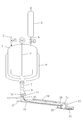
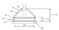
- FIG. 1 is a schematic configuration diagram illustrating an apparatus for producing a liquid crystalline polyester resin including a die head to which a valve is connected.
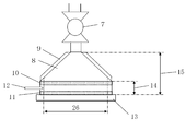
- FIG. 2 is a schematic front view showing the die head of FIG.
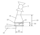
- FIG. 3 is a schematic side view showing the die head of FIG.
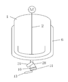
- FIG. 4 is a partial schematic configuration diagram illustrating a liquid crystalline polyester resin manufacturing apparatus including a die head with a built-in discharge valve.
- FIG. 5 is a schematic front view showing the die head of FIG.
- the liquid crystalline polyester resin of the present invention is a resin that forms an anisotropic molten phase, and examples thereof include liquid crystalline polyester resins having an ester bond such as liquid crystalline polyester and liquid crystalline polyester amide.
- the structural unit constituting the liquid crystalline polyester resin is preferably a structural unit selected from, for example, an aromatic oxycarbonyl unit, an aromatic and / or aliphatic dioxy unit, an aromatic and / or aliphatic dicarbonyl unit.
- aromatic oxycarbonyl unit examples include structural units formed from p-hydroxybenzoic acid, 6-hydroxy-2-naphthoic acid and the like, and p-hydroxybenzoic acid is preferable.
- aromatic or aliphatic dioxy units include 4,4′-dihydroxybiphenyl, hydroquinone, 3,3 ′, 5,5′-tetramethyl-4,4′-dihydroxybiphenyl, t-butylhydroquinone, and phenylhydroquinone.
- 2,6-dihydroxynaphthalene, 2,7-dihydroxynaphthalene, 2,2-bis (4-hydroxyphenyl) propane and 4,4′-dihydroxydiphenyl ether ethylene glycol, 1,3-propylene glycol, 1,4- Examples thereof include structural units formed from butanediol, and 4,4′-dihydroxybiphenyl and hydroquinone are preferred.
- aromatic or aliphatic dicarbonyl unit include terephthalic acid, isophthalic acid, 2,6-naphthalenedicarboxylic acid, 4,4′-diphenyldicarboxylic acid, 1,2-bis (phenoxy) ethane-4,4 ′.
- liquid crystalline polyester resin examples include a structural unit generated from p-hydroxybenzoic acid, a structural unit generated from 4,4′-dihydroxybiphenyl, a structural unit generated from hydroquinone, and generated from terephthalic acid and / or isophthalic acid.
- Liquid crystalline polyester resin comprising the above structural units, structural units produced from p-hydroxybenzoic acid, structural units produced from ethylene glycol, structural units produced from 4,4′-dihydroxybiphenyl, structural units produced from hydroquinone, terephthalate Liquid crystalline polyester resin composed of structural units generated from acid and / or isophthalic acid, structural unit generated from p-hydroxybenzoic acid, structural unit generated from ethylene glycol, structural unit generated from 4,4′-dihydroxybiphenyl
- a liquid crystalline polyester resin comprising a structural unit produced from terephthalic acid and / or isophthalic acid, a structural unit produced from p-hydroxybenzoic acid, a structural unit produced from hydroquinone, a structural unit produced from 4,4′-dihydroxybiphenyl, Examples thereof include a liquid crystalline polyester resin composed of a structural unit formed from 2,6-naphthalenedicarboxylic acid and a structural unit generated from terephthalic acid.
- preferred combinations include a structural unit generated from p-hydroxybenzoic acid, a structural unit generated from hydroquinone, a structural unit generated from 4,4′-dihydroxybiphenyl, and a structural unit generated from terephthalic acid and / or isophthalic acid.
- a structural unit generated from p-hydroxybenzoic acid a structural unit generated from ethylene glycol, a structural unit generated from 4,4′-dihydroxybiphenyl, a structural unit generated from terephthalic acid and / or isophthalic acid
- the combination which becomes is illustrated.
- liquid crystalline polyester resin forming the anisotropic molten phase examples include liquid crystalline polyester resins composed of the structural units of the following (I), (II), (III), (IV) and (V). .
- the structural unit (I) is a structural unit generated from p-hydroxybenzoic acid
- the structural unit (II) is a structural unit generated from 4,4′-dihydroxybiphenyl
- the structural unit (III) is a structure generated from hydroquinone.
- the structural unit (IV) represents a structural unit generated from terephthalic acid
- the structural unit (V) represents a structural unit generated from isophthalic acid.
- this liquid crystalline polyester resin will be described as an example.
- the copolymerization amount of the structural units (I), (II), (III), (IV) and (V) is arbitrary. However, in order to exhibit the characteristics of the liquid crystalline polyester resin, the following copolymerization amount is preferable.
- the structural unit (I) is preferably 65 to 80 mol% based on the total of the structural units (I), (II) and (III). More preferably, it is 68 to 78 mol%.
- the structural unit (II) is preferably 55 to 85 mol% with respect to the total of the structural units (II) and (III). More preferably, it is 55 to 78 mol%, and most preferably 58 to 73 mol%.
- the structural unit (IV) is preferably 50 to 95 mol% with respect to the total of the structural units (IV) and (V). More preferably, it is 55 to 90 mol%, and most preferably 60 to 85 mol%.
- the sum of the structural units (II) and (III) and the sum of (IV) and (V) are substantially equimolar.
- substantially equimolar means that the structural unit constituting the polymer main chain excluding the terminal is equimolar. For this reason, the aspect which does not necessarily become equimolar when it includes even the structural unit which comprises the terminal can satisfy the requirement of “substantially equimolar”.
- liquid crystalline polyester resin whose structural unit (I) is 30 mol% or more of the total of all five structural units.
- the liquid crystalline polyester resin is preferable because the target heat resistance can be obtained.
- the liquid crystalline polyester resin preferably used includes aromatic dicarboxylic acids such as 3,3′-diphenyldicarboxylic acid and 2,2′-diphenyldicarboxylic acid in addition to the components constituting the structural units (I) to (V).
- aliphatic dicarboxylic acid compounds such as adipic acid, azelaic acid, sebacic acid and dodecanedioic acid
- alicyclic dicarboxylic acid compounds such as hexahydroterephthalic acid, chlorohydroquinone, 3,4'-dihydroxybiphenyl, 4,4 ' -Aromatic diol compounds such as dihydroxydiphenyl sulfone, 4,4'-dihydroxydiphenyl sulfide, 4,4'-dihydroxybenzophenone, 3,4'-dihydroxybiphenyl, propylene glycol, 1,4-butanediol, 1,6- Hexanediol, neopentylglyce
- aliphatic diol compounds and alicyclic diol compounds such as 1,4-cyclohexanediol and 1,4-cyclohe
- Examples of the raw material for the liquid crystalline polyester resin include aromatic hydroxycarboxylic acid compounds, diol compounds, dicarboxylic acid compounds, and amino group-containing monomers.
- aromatic hydroxycarboxylic acid compounds such as p-hydroxybenzoic acid, diol compounds such as 4,4'-dihydroxybiphenyl, hydroquinone and ethylene glycol, and aromatic dicarboxylic acid compounds such as terephthalic acid and isophthalic acid are preferred.
- monomers other than hydroquinone ethylene glycol, p-hydroxybenzoic acid, 4,4'-dihydroxybiphenyl, terephthalic acid and isophthalic acid
- the following monomers may be mentioned.
- the aromatic hydroxycarboxylic acid compound include 6-hydroxy-2-naphthoic acid
- examples of the aromatic dicarboxylic acid compound include 2,6-naphthalenedicarboxylic acid, 4,4′-diphenyldicarboxylic acid, 1, 2-bis (phenoxy) ethane-4,4′-dicarboxylic acid, 1,2-bis (2-chlorophenoxy) ethane-4,4′-dicarboxylic acid, 4,4′-diphenyl ether dicarboxylic acid, and the like.
- aromatic diol compound examples include resorcinol, t-butylhydroquinone, phenylhydroquinone, chlorohydroquinone, 2,6-dihydroxynaphthalene, 2,7-dihydroxynaphthalene, 3,4'-dihydroxybiphenyl, 2,2-bis (4 -Hydroxyphenyl) propane, 4,4′-dihydroxydiphenyl ether, and the like.
- monomer having an amino group examples include p-aminobenzoic acid and p-aminophenol.
- the following production method is preferably exemplified.
- the following production method is explained by taking as an example the synthesis of a liquid crystalline polyester resin composed of p-hydroxybenzoic acid, 4,4′-dihydroxybiphenyl, hydroquinone, terephthalic acid and isophthalic acid. Is not limited to these, and each can be replaced with polyethylene terephthalate, other hydroxycarboxylic acid compounds, aromatic diol compounds or aromatic dicarboxylic acid compounds, and can be produced according to the following method.
- the content of each structural unit in the liquid crystalline polyester resin can be calculated by the following treatment. That is, the liquid crystalline polyester is weighed into an NMR (nuclear magnetic resonance) test tube, dissolved in a solvent in which the liquid crystalline polyester is soluble (for example, a pentafluorophenol / heavy tetrachloroethane-d 2 mixed solvent), and 1 H- NMR spectrum measurement is performed. The content of each structural unit can be calculated from the peak area ratio derived from each structural unit.
- a predetermined amount of a monomer mixture and acetic anhydride are charged into a reaction tank equipped with a raw material inlet, a stirring blade, a rectifying tube, a distilling tube, and a pressure reducing device, and provided with a discharge port at the lower portion. Heat with stirring and acetylate the hydroxyl group with reflux. Thereafter, the temperature is raised to a predetermined temperature while distilling acetic acid from the reaction tank via the distillation pipe. If a specified amount of acetic acid is distilled off, the reaction vessel is depressurized and acetic acid generated by the polycondensation reaction is obtained. Is distilled.
- the deacetic acid polycondensation reaction is terminated when the prescribed stirring torque is reached.
- stirring is stopped, the reaction vessel is pressurized with nitrogen, and the polymer is formed into a strand shape from the discharge port at the bottom of the reaction vessel via the nozzle hole, and pelletized with a cutting device. To do.
- the number of reaction tanks is not particularly limited, and the reaction can be performed in one tank or two or more reaction tanks.
- a preferred method example in the case of performing two tanks is as follows. First, after the raw material monomer and acetic anhydride are charged into the reaction tank 1 and subjected to acetylation reaction, deacetic acid polycondensation is performed up to a predetermined temperature and a predetermined amount of acetic acid distillate. Next, the reaction liquid in the reaction tank 1 is transferred to the reaction tank 2 through a transfer pipe connected to the reaction tank 2, and deacetic acid polycondensation is further performed to a predetermined temperature and a predetermined amount of acetic acid distillate.
- the polycondensation is further advanced, and the reaction is terminated when a predetermined stirring torque is reached.
- the reaction tank is used in one tank or two or more tanks, the last reaction tank that has the discharge port and performs discharge is called a polycondensation reaction tank.
- the amount of acetic anhydride used is preferably 1.00 to 1.20 molar equivalent of the total of phenolic hydroxyl groups in the liquid crystalline polyester resin raw material to be used. More preferably, it is 1.03 to 1.16 molar equivalent.
- the acetylation reaction is preferably carried out while refluxing at a temperature of 125 ° C. or higher and 150 ° C. or lower until the residual amount of monoacetylated aromatic diol falls within a specific range.
- a reaction vessel equipped with a reflux tube, a rectifying column, and a condenser can be used as an apparatus for the acetylation reaction.
- the reaction time for acetylation is roughly 1 to 5 hours, but the time until the residual amount of monoacetylated aromatic diol reaches a specific range depends on the liquid crystalline polyester resin raw material used and the reaction temperature. Is also different.
- the reaction time is 1.0 to 2.5 hours. The higher the reaction temperature, the shorter the time required, and the higher the molar ratio of acetic anhydride to the phenolic hydroxyl terminal, the shorter the time.
- the top temperature of the rectifying column is preferably in the range of 115 ° C to 150 ° C. More preferably, it is in the range of 130 ° C to 145 ° C. If the column top temperature is too low, a large amount of unreacted acetic anhydride remains in the system, which may cause the coloring of the polymer or increase the amount of gas during heating residence. On the other hand, when the column top temperature is higher than 150 ° C., the monomers are distilled out of the system, and there is a possibility that the composition is shifted or the polymerization rate is lowered.
- the acetic acid to be distilled contains excess acetic anhydride and monomers, but the mass% of the monomers excluding acetic acid and acetic anhydride is preferably 1% by mass or less, and 0.5% by mass or less. More preferred.
- the deacetic acid polycondensation reaction is preferably a melt polymerization method in which the reaction is performed under reduced pressure at a temperature at which the liquid crystalline polyester resin melts to complete the polymerization reaction.
- the melt polymerization method is an advantageous method for producing a uniform polymer, and is preferable because a polymer with less gas generation can be obtained.
- the final polymerization temperature is preferably about melting point + 20 ° C., preferably 370 ° C. or less.
- the degree of vacuum during the polymerization is usually 13.3 Pa (0.1 torr) to 2666 Pa (20 torr), preferably 1333 Pa (10 torr) or less, more preferably 667 Pa (5 torr) or less.
- a preferable polymerization rate is 0.5 to 1 hour after the degree of vacuum becomes 667 Pa or less until the specified polymerization stirring torque is detected and the polymerization is completed.
- the polycondensation reaction of the liquid crystalline polyester resin proceeds even without catalyst, but metal compounds such as stannous acetate, tetrabutyl titanate, potassium acetate and sodium acetate, antimony trioxide, and magnesium metal can also be used.
- the method for producing liquid crystalline polyester resin pellets of the present invention includes a die head having a discharge port for discharging molten liquid crystalline polyester resin supplied from a reaction tank to a die head through a valve from the die head, and discharging from the die head.
- the molten liquid crystalline polyester resin is removed from the reaction vessel to the valve.
- the liquid crystal is supplied to the die head through the die and discharged and solidified from the die head through the discharge port so as to form a strand group.
- the molten liquid crystalline polyester resin that has been subjected to the polycondensation reaction in the polycondensation reaction tank 1 is supplied to the die head 8 with the opening / closing valve of the discharge valve 7 being opened,
- the strands 16 are discharged through the hole plate 10 and the discharge port plate 11 having a plurality of base holes.
- the strand group 16 is discharged into the trough 18 in which the cooling water is flown and solidified while being cooled by the cooling water supplied from the cutter cooling water supply line 17, and the strand group take-up roll 20 and the strand group cutting rotary blade 21.
- liquid crystalline polyester resin pellets 22 After being taken by the strand group take-up roll 20, it is cut in water by the strand group cutting rotary blade 21 to obtain liquid crystalline polyester resin pellets 22.
- the obtained liquid crystalline polyester resin pellets 22 are subjected to a draining process to remove moisture, and are transported and stored in a pellet receiving tank or the like.
- a strand group cooling spray 19 may be provided above the trough 18 or at a position where the strand group is dropped in order to maintain cooling and running stability of the transported strand group.
- one or more valves are provided between the polycondensation reaction tank 1 and the die head 8 or at an upper position of the die head 8. From the viewpoint of cost and maintenance, it is preferable to have one valve. Although there is no restriction
- the position of the die head 8 is located at the bottom of the polycondensation reaction tank 1 and is connected to the polycondensation reaction tank 1 with a discharge valve 7 sandwiched between them.
- the die head 28 having the discharge valve 25 built therein it is directly connected to the bottom of the polycondensation reaction tank 1.
- the die head 8 may have a heating body in order to heat the polymer that passes through or stays in the interior, and the installation position and type of the heating body are not particularly limited, and the die head 8 can be attached to the inner wall surface of the die head 8.
- the inner wall surface of the die head 8 may be embedded, or the inner wall surface may be indirectly heated via the wall of the die head 8 by being attached to the outer wall surface of the die head, or the discharge valve 7 portion may be heated.
- Examples of the type of heating element include a method of covering and heating with a coil, a jacket, a belt-like heating element, and the like. Among these, the method of attaching the jacket 9 to the outer wall surface is preferable in that the heating range can be heated at a uniform temperature.
- a heating method of the heating body a method of circulating the inside of the coil or jacket 9 with vapor or a liquid heating medium, a method of heating the heating body with a heating wire, or the like is used.
- a method of circulating with a vapor or a liquid heat medium is preferable, and a method of circulating with a pump with a liquid heat medium in the jacket 9 is more preferable. With this method, the temperature can be stably controlled.
- the discharge head plate 11 is provided in the die head 8. Further, an opening / closing valve is preferably provided below the discharge port plate 11 for the purpose of enclosing the residual polymer and keeping the mouthpiece hole warm.
- the shape of the on-off valve is not particularly limited and is generally known and has no problem. Specific examples include a slit valve, a ball valve, and a slide plate valve 13. In this case, it is also possible to function as an on-off valve by pre-bonding the mouthpiece hole with a valve body plate or the like until the next batch is discharged, and detaching the valve body plate at the time of discharge to perform discharge.
- the on-off valve is preferably a slit valve or a slide plate valve 13 and is excellent in terms of operation and maintenance.
- the shape of the die head 8 is such that the ratio (H2 / W) of the height (H2) / bottom width (W) of the portion where the liquid crystalline polyester resin becomes wider in the direction of flowing toward the discharge port is 0.10 to It is preferably 0.50. 0.15 to 0.40 is more preferable. In the case of 0.1 or more, each strand discharged from the base part can obtain a uniform shear rate and can be stably discharged. If it is 0.50 or less, the volume inside the die head does not increase, the residual polymer is difficult to accumulate, and the strands have a uniform thickness, so that a good pellet shape can be obtained.
- the shape of the die head 8 is preferably such that the ratio (D / W) of the depth (D) of the bottom of the die head 8 / the width (W) of the bottom is 0.03 to 0.5. More preferably, it is 0.05 to 0.35. When it is 0.03 or more, fusion between strands can be reduced, and the pellet shape can be made uniform, which is preferable. If it is 0.5 or less, the volume inside the die head does not increase, and the residual polymer hardly accumulates, and it is difficult to become a high melting point foreign matter. Moreover, since a strand becomes uniform thickness, a favorable pellet shape can be obtained.
- the depth (D) and the width (W) of the bottom side of the die head 8 represent the inner diameter of the die head 8 in contact with the die.
- the product of depth (D) and base width (W) represents the cross-sectional area of the portion where the polymer stays.
- the longer side of the bottom of the die head 8 is the width (W)
- the shorter side is the depth (D).
- At least one perforated plate 10 is installed between the discharge valve 7 and the discharge port.
- the shape of the perforated plate 10 there are no particular restrictions on the shape of the perforated plate 10, but specifically, a wire netting shape in which a wire-like stainless steel is folded in a lattice shape, a plate having a plurality of holes, and further on the plate For example, a wire mesh filter is fixed and installed. Without this perforated plate, residual polymer tends to accumulate partially, or foreign matters such as carbides are clogged in the base of the discharge port, resulting in high pressure loss and the target discharge time cannot be obtained. There is a possibility that replacement is necessary, or a thread-like strand is wound around a cutter or a roller and causes a discharge trouble.
- the number of perforated plates to be installed is one or more, but in consideration of production cost and maintainability, one or more and two or less are preferable. In the case of two, a method in which one wire mesh filter is installed on the upper side of one plate is preferable.
- the diameter of the filter mesh opening or the plate hole is 0.1 to 1.2 times the diameter of the nozzle hole of the discharge port. 0.5 to 1.0 times is more preferable. If it is less than 0.1 times, it can be expected as a foreign matter collecting effect, but the pressure loss increases, and there is a possibility that the target discharge time cannot be obtained or the residual polymer in the die head is not sufficiently replaced. If it is larger than 1.2 times, the foreign matter cannot be collected effectively, and the foreign matter is mixed into the product, or the mouthpiece hole becomes clogged and the mouthpiece needs to be replaced. May cause discharge problems.
- the diameter of the filter mesh opening or the hole of the plate here is an average hole diameter obtained by measuring the diameter of 20 randomly selected holes, and in the case of less than 20, the average hole diameter of all the hole diameters. is there.
- the average pore diameter of the smaller aperture or hole diameter is adopted.
- the position of the mesh opening of the filter and the hole of the plate is not particularly limited, but it is preferable to have a mesh opening or hole on almost the entire surface. Having mesh openings or pores on almost the entire surface is preferable because there is little retention of the residual polymer and the polymer can pass uniformly.
- the mesh openings of the filter and the arrangement of the holes in the plate are not particularly limited, but it is preferable to arrange them at regular intervals. When the holes in the plate are arranged in two or more rows, they are arranged in a staggered pattern or a honeycomb pattern. It is preferable to do. By arranging in a zigzag or honeycomb shape, the number of holes can be increased, so that the retention of the residual polymer can be reduced and the pressure loss of the plate portion can be reduced.
- the relationship between the arrangement of the holes in the perforated plate and the arrangement of the nozzle holes in the discharge port is not particularly limited, and may be the same or different, so that they are equally spaced so as not to impair the polymer flow state. It only has to be arranged.
- the ratio (H1 / H2) between the height (H1) between the uppermost perforated plate and the discharge port (H1) and the height (H2) of the die head is in the range of 0.2 to 0.6. Is preferable, and 0.3 to 0.5 is more preferable. If it is 0.2 or more, the volume inside the die head does not increase and the residual polymer is difficult to accumulate, the strands near the ends of the die part do not become thin, the pellet shape varies, and the die clogging easily occurs. It is preferable because it never happens. If it is 0.6 or less, it is difficult for residual polymer to accumulate between the perforated plate and the die, and it becomes difficult for the die to clog, or each strand discharged from the die part can obtain a uniform shear rate. Therefore, there is no unevenness in the thickness of the strands, no fluttering up and down, and no flow failure of the strand group. Therefore, stable discharge can be performed.
- the diameter of the nozzle hole of the discharge port is 3 mm to 6 mm. More preferably, it is 3.5 mm to 6.0 mm, and most preferably 4.0 mm to 5.5 mm.
- the diameter of the die hole is less than 3 mm, the pressure loss of the die part becomes large, a higher discharge pressure is required, the strand is also thin, curved, meandering, and good pellets cannot be obtained.
- the diameter of the die hole is larger than 6 mm, the strand group becomes thick and rigid, fluttering up and down occurs, the flow of the strand group becomes poor, the number of continuous ball pellets and uncut pellets increases, and good pellets cannot be obtained. There is a fear.
- the number of nozzle holes of the discharge port is preferably 20 or more, and more preferably 40 or more. In order to obtain an excellent pellet shape, it is necessary for the remaining polymer in the die head to stay less and the entire strand group to travel stably, and when the number of nozzle holes is large, that is, the strand group is large. In some cases, more stable liquid crystalline polyester resin pellets can be obtained.
- the arrangement of the nozzle holes of the discharge port is not particularly limited, but is preferably an arrangement in which the strand groups do not overlap when the strand groups are taken up. Specific examples include the arrangement of the nozzle holes in a horizontal row or a staggered pattern. The staggered pattern is preferable because the strand groups do not overlap and the target number of nozzle holes can be obtained. Furthermore, it is preferable to provide the die holes at positions close to both ends of the die head because residual polymer is unlikely to collect at both ends of the die.
- the shear rate of the liquid crystalline polyester resin per nozzle hole of the discharge port of the die head is preferably 150 [1 / second] to 3000 [1 / second], more preferably 250 [1 / second] to 2000 [1 / second].
- the speed is 150 [1 / second] or more because a running failure of the strand group is less likely to occur in a low shear rate region such as immediately after the start of discharge. If it is 3000 [1 / second] or less, the residual polymer in the die head is sufficiently substituted, and it is difficult to become a high melting point foreign material. Furthermore, it is preferable because the take-up of the strand group is stable and the shape of the pellet is stable.
- the shear rate of the liquid crystalline polyester resin is a value obtained by the following formula (1) for the shear rate per nozzle hole of the discharge port.
- Resin shear rate (1 / second) 80000/9 ⁇ discharge rate per unit time (kg / hr) / [resin density (g / cm 3 ) ⁇ number of nozzle holes (pieces) ⁇ ⁇ (Circumferential ratio) ⁇ diameter of base hole (mm) 3 ]
- the liquid crystalline polyester resin in the present invention has a melt viscosity ( ⁇ a 200) and a shear rate of 5000 at a shear rate of 200 [1 / second] of the liquid crystalline polyester resin at the temperature when discharged from the die hole of the discharge port of the die head.
- the melt viscosity ( ⁇ a5000) at [1 / second] is preferably 1.5 or more, more preferably 2.0 or more.
- 10.0 or less is preferable, More preferably, it is 7.0 or less. It is preferable that the following formula (2) is satisfied, and more preferably, the following formula (3) is satisfied.
- the strand thickness becomes uniform, and a stable pellet shape can be obtained.
- the strands are moderately stretched and are not easily broken.
- the value of ( ⁇ a200) / ( ⁇ a5000) is 10.0 or less, it is preferable in a low shear rate region such as immediately after the start of discharge because the strands are not easily stretched and thickened, and the strands are less likely to run poorly. It is preferable because the residual polymer is easily replaced.
- the melt viscosity at a shear rate of 200 [1 / sec] and the melt viscosity at a shear rate of 5000 [1 / sec] can be measured, for example, using a Koka flow tester.
- Formula (2) 1.5 ⁇ ( ⁇ a200) / ( ⁇ a5000) ⁇ 10.0
- Formula (3) 2.0 ⁇ ( ⁇ a200) / ( ⁇ a5000) ⁇ 7.0
- the inside of the reaction vessel is pressurized to, for example, about 0.02 to 0.5 MPa at a temperature at which the liquid crystalline polyester resin is melted, It discharges in a strand form from the discharge port of the die head connected to the lower part of the condensation reaction tank. It is preferable that the strand group is discharged into a trough in which cooling water is flowed, cooled and solidified in cooling water, and cut into pellets with a cutter to obtain liquid crystalline polyester resin pellets.
- the discharged strand has no particular problem even if the central part is in a semi-molten state, and solidifies to such an extent that the pellets are fused together or whisker-like projections do not occur when discharged into pellets with a cutter. If it is possible, there is no problem.
- the cutter has no problem whether the trough surface is close to vertical or horizontal, and it can be selected in consideration of the viscosity of the liquid crystalline polyester resin to be discharged and the installation space. .
- the take-up speed of the strand group needs to be adjusted so that the strand group does not flutter or meander, and is preferably 20 to 100 m / min, more preferably 30 to 80 m / min.
- the strand group take-up speed here refers to the rotational speed of the cutter when the strand group is directly taken up by the cutter unit.
- the strand group is once taken up by a take-off roller or the like and then cut by the cutter, the strand group is taken up. Represents the rotation speed of the roll.
- the polycondensation reaction can be completed by a solid phase polymerization method.
- the polymer or oligomer of the liquid crystalline polyester resin of the present invention is pulverized with a pulverizer, and the liquid crystalline polyester resin has a melting point of ⁇ 50 ° C. to a melting point of ⁇ 5 ° C. for 1 to 50 hours in a nitrogen stream or under reduced pressure.
- a method of heating and polycondensing to a desired degree of polymerization to complete the reaction can be mentioned.
- Solid phase polymerization is an advantageous method for producing polymers with a high degree of polymerization.
- the melt viscosity of the liquid crystalline polyester resin pellet obtained in the present invention is preferably 10 to 500 Pa ⁇ s. More preferably, it is 12 to 200 Pa ⁇ s.
- the melt viscosity is a value measured with a Koka flow tester under a melting point (Tm) + 10 ° C. to + 20 ° C. under a shear rate of 1000 [1 / second].
- the melting point of the liquid crystalline polyester resin in the present invention is not particularly limited, but it is preferable to combine copolymer components so as to be 280 ° C. or higher for use in high heat resistance applications.
- a filler in order to impart mechanical strength and other characteristics of the liquid crystalline polyester resin, a filler can be further blended.
- the filler is not particularly limited, but fillers such as a fiber, a plate, a powder, and a granule can be used.
- a known coupling agent for example, a silane coupling agent, a titanate coupling agent, etc.
- other surface treatment agents for example, a silane coupling agent, a titanate coupling agent, etc.
- glass fiber is particularly preferably used from the viewpoint of balance between availability and mechanical strength.
- the type of glass fiber is not particularly limited as long as it is generally used for reinforcing resin, and can be selected from, for example, long fiber type or short fiber type chopped strands and milled fibers. Two or more of these can be used in combination.
- a weakly alkaline glass fiber is excellent in terms of mechanical strength and can be preferably used.
- the glass fiber is preferably treated with an epoxy-based, urethane-based, acrylic-based coating or sizing agent, and epoxy-based is particularly preferable. Further, it is preferably treated with a silane-based or titanate-based coupling agent or other surface treatment agent, and an epoxysilane or aminosilane-based coupling agent is particularly preferable.
- the glass fiber may be coated or bundled with a thermoplastic resin such as an ethylene / vinyl acetate copolymer or a thermosetting resin such as an epoxy resin.
- a thermoplastic resin such as an ethylene / vinyl acetate copolymer or a thermosetting resin such as an epoxy resin.
- the blending amount of the filler is usually 30 to 200 parts by weight, preferably 40 to 150 parts by weight with respect to 100 parts by weight of the liquid crystalline polyester resin.
- liquid crystalline polyester resin of the present invention includes antioxidants and heat stabilizers (for example, hindered phenols, hydroquinones, phosphites and substituted products thereof), ultraviolet absorbers (for example, resorcinol, salicylate), phosphorous acid.
- antioxidants and heat stabilizers for example, hindered phenols, hydroquinones, phosphites and substituted products thereof
- ultraviolet absorbers for example, resorcinol, salicylate
- phosphorous acid for example, phosphorous acid.
- Coloring agents including acid salts, hypophosphites, etc., lubricants and mold release agents (such as montanic acid and its metal salts, its esters, their half esters, stearyl alcohol, stearamide and polyethylene wax), dyes and pigments Carbon black, crystal nucleating agent, plasticizer, flame retardant (bromine flame retardant, phosphorus flame retardant, red phosphorus, silicone flame retardant, etc.), flame retardant aid, and antistatic agent Add other additives such as ordinary additives and polymers other than thermoplastic resins to further give the desired properties It is possible.
- a liquid crystalline polyester resin composition may be obtained by melt-kneading at a temperature of 180 to 350 ° C., more preferably 250 to 320 ° C. using a Banbury mixer, rubber roll machine, kneader, single-screw or twin-screw extruder, and the like. it can.
- 1) a liquid crystal polyester resin, a bulk kneading method with optional fillers and other additives and 2) a liquid crystal polyester resin composition containing a high concentration of other additives in the liquid crystalline polyester.
- thermoplastic resin filler and other additives to the specified concentration (master pellet method), 3) liquid crystalline polyester resin and other additives
- Any method may be used such as a split addition method in which a part of the agent is kneaded once and then the remaining filler and other additives are added.
- the liquid crystalline polyester resin of the present invention and the liquid crystalline polyester resin composition containing the same are excellent in surface appearance (color tone) and mechanical properties, heat resistance, by a molding method such as normal injection molding, extrusion molding, and press molding. It can be processed into flame-retardant three-dimensional molded products, sheets, containers, pipes, films and the like. In particular, it is suitable for electrical and electronic parts obtained by injection molding.
- the liquid crystalline polyester resin thus obtained and the liquid crystalline polyester resin composition containing the same are, for example, various gears, various cases, sensors, LED lamps, connectors, sockets, resistors, relay cases, switches, coil bobbins, Capacitors, variable capacitor cases, optical pickups, oscillators, various terminal boards, transformers, plugs, printed wiring boards, tuners, speakers, microphones, headphones, small motors, magnetic head bases, power modules, housings, semiconductors, liquid crystal display parts, Electrical / electronic parts such as FDD carriage, FDD chassis, HDD parts, motor brush holder, parabolic antenna, computer-related parts; VTR parts, TV parts, iron, hair dryer, rice cooker Products, microwave oven parts, acoustic parts, audio equipment parts such as audio / laser discs (registered trademark) / compact discs, lighting parts, refrigerator parts, air conditioner parts, typewriter parts, word processor parts Representative of product parts, office computer related parts, telephone related parts, facsimile related parts, copying machine related parts, cleaning jigs
- Machine-related parts optical instruments such as microscopes, binoculars, cameras, watches, precision machine-related parts; alternator terminals, alternator connectors, IC regulators, light dimmer potentiometer bases, various valves such as exhaust gas valves, fuel Relations / exhaust system / intake system pipes, air intake nozzle snorkel, intake manifold, fuel pump, engine coolant joint, carburetor main body, carburetor spacer, exhaust gas sensor, coolant sensor, oil temperature sensor, throttle position sensor, crank Shaft position sensor, air flow meter, brake pad wear sensor, thermostat base for air conditioner, motor insulator for air conditioner, separator, heating hot air flow control valve, brush holder for radiator motor, water pump impeller, turbine vane, wiper motor Parts, distributor, starter switch, starter relay, transmission wire harness , Window washer nozzle, air conditioner panel switch board, coil for fuel related electromagnetic valve, connector for fuse, horn terminal, electrical component insulation plate, step motor rotor, lamp socket, lamp reflector, lamp housing, brake piston, solenoid bobbin,
- magnetic recording media film When used as a film, magnetic recording media film, photographic film, capacitor film, electrical insulation film, packaging film, drafting film, ribbon film, and sheet use include automotive interior ceilings, door trims, and instrument panels. It is useful for pad materials, bumper and side frame cushioning materials, sound absorbing pads such as the back of bonnets, seat materials, pillars, fuel tanks, brake hoses, nozzles for window washer fluid, air conditioner refrigerant tubes and their peripheral parts.
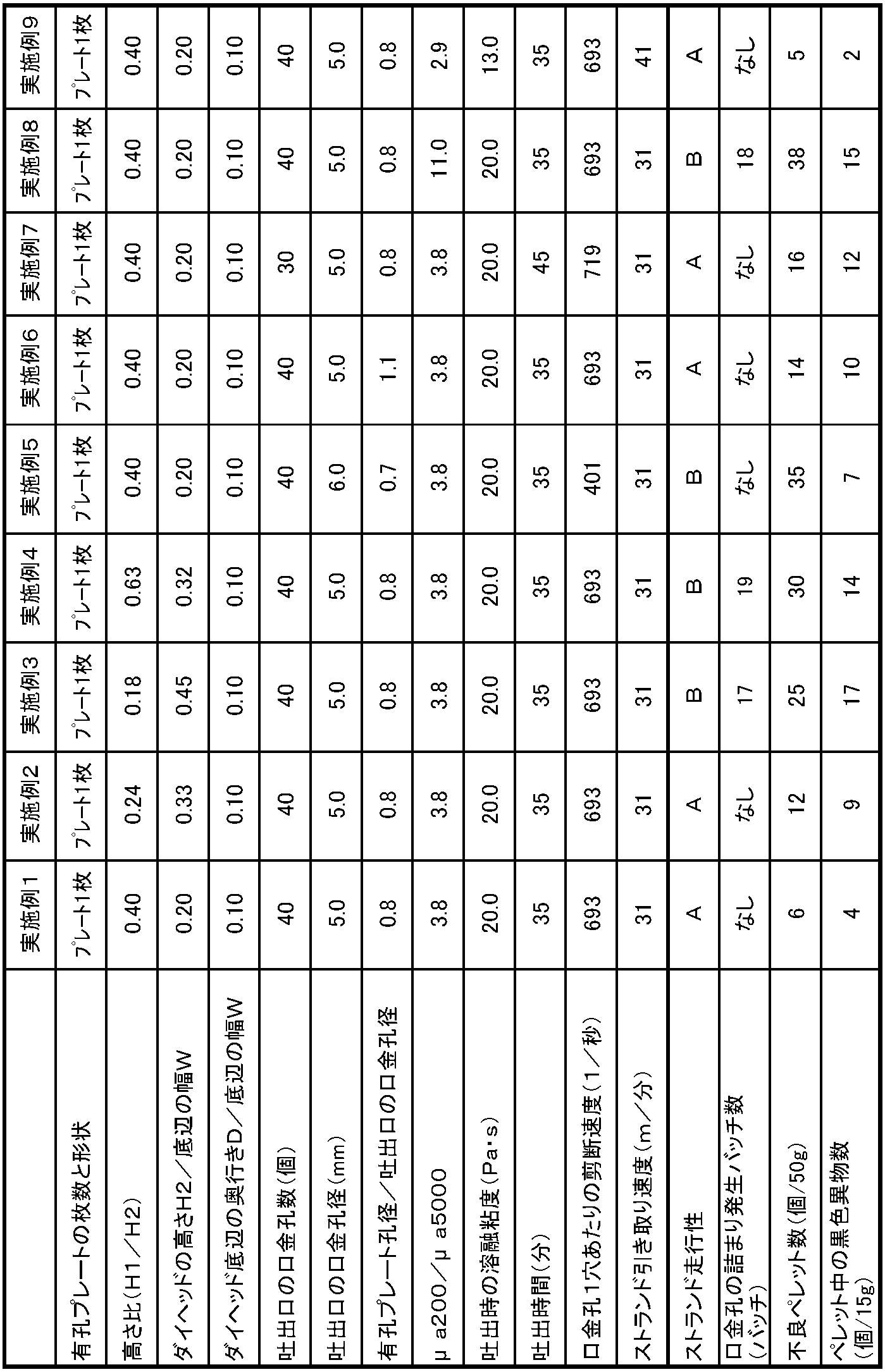
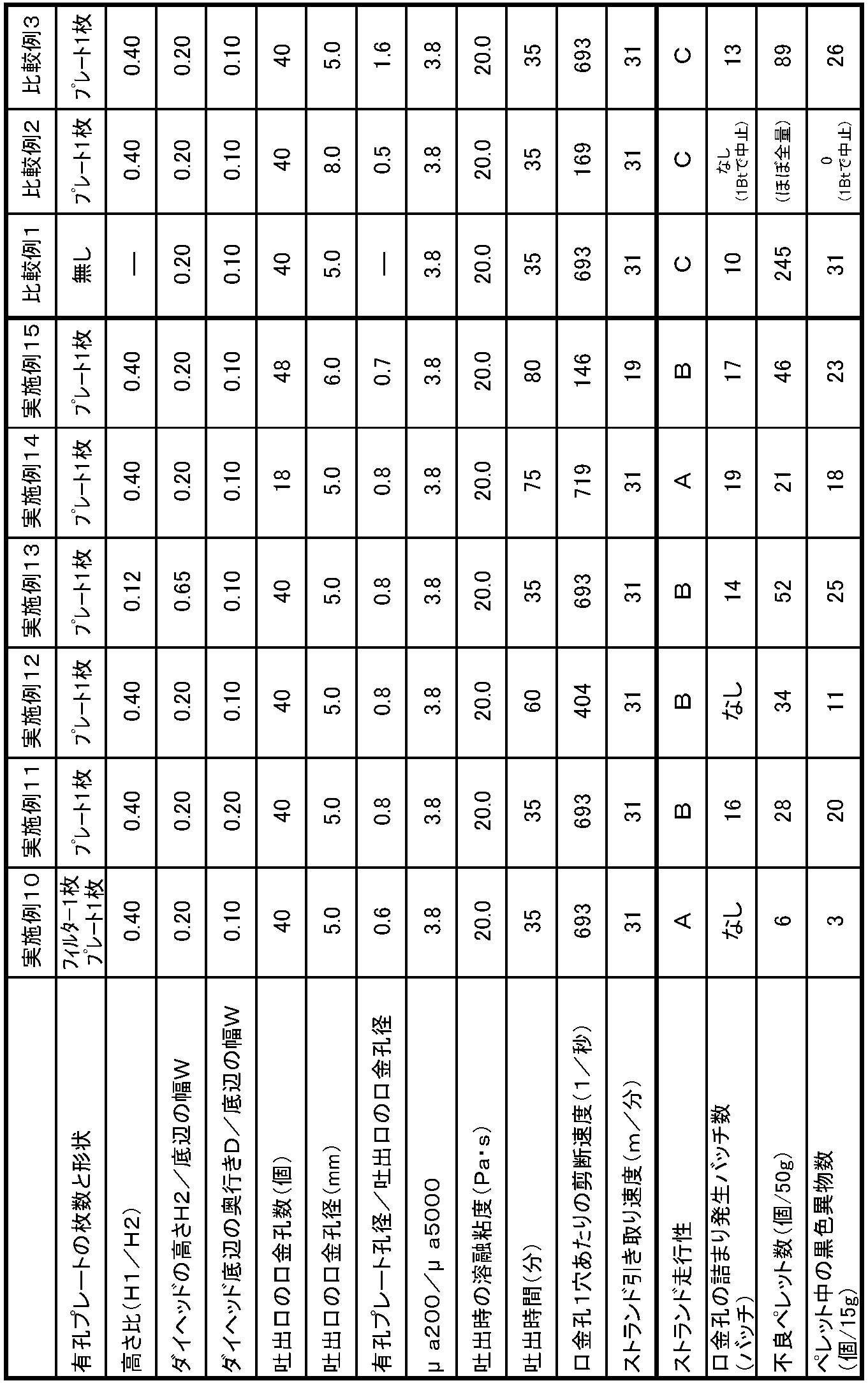
- Examples 1 to 15 and Comparative Examples 1 to 3 were each performed a maximum of 20 times (20 batches), and the evaluations shown in the following (1) to (8) were performed. In addition, when the test was finished with a batch that was less than the maximum number of batches, the average value up to the finished batch was described.
- Tm melting point
- thermometer element is inserted between a plate having a plurality of holes (perforated plate) and a plate having a plurality of base holes (discharge port plate), and the liquid crystal properties during discharge The temperature of the polyester resin was measured.
- a composition ratio measured composition ratio measured liquid crystalline polyester resin of the liquid crystalline polyester resin was carried out by 1 H- nuclear magnetic resonance spectrum (1 H-NMR) measurement.
- 50 mg of liquid crystalline polyester resin was weighed into an NMR sample tube and dissolved in 800 ⁇ L of a solvent of pentafluorophenol / 1,1,2,2-tetrachloroethane-d 2 (mixing ratio: 65/35 [w / w%]). Then, 1 H-NMR measurement was performed at an observation frequency of 500 MHz and a temperature of 80 ° C. using a UNITY INOVA 500 type NMR apparatus (manufactured by Varian), and observed at around 4.5 to 5 ppm and around 7 to 9.5 ppm. The composition was analyzed from the peak area ratio derived from each structural unit.
- Example 1 As shown in FIGS. 1 to 3, a 2500-L polycondensation reaction tank equipped with a stirring blade 2, a distillation pipe 4, a distillation acetic acid container (not shown), a pressure reducing device (not shown), and a discharge port at the bottom. 1 was used.
- a die head 8 connected to a discharge valve 7 is attached to the bottom of the polycondensation reaction tank 1, and a plate (a perforated plate 10) having a plurality of holes having a diameter of 4.0 mm is attached to the bottom of the die head 8.
- a discharge port plate 11 having 40 nozzle holes with a diameter of 5.0 mm was attached as a discharge port.
- the ratio (H1 / H2) of the height 14 (H1) from the perforated plate 10 to the discharge port plate 11 and the height 15 (H2) of the die head 8 was 0.40.
- the ratio (H2 / W) of the height 15 (H2) of the die head 8 to the width 26 (W) of the base was 0.20.
- the ratio (D / W) of the depth 27 (D) of the bottom side of the die head 8 to the width 26 (W) of the bottom side was 0.10.
- the numerical values of W and D are measured as internal dimensions. That is, W and D respectively indicate the width and depth of the hollow portion surrounded by the inner wall of the die head 8 indicated by broken lines in FIGS.
- the die head 8 has a jacket 9 on the outer wall surface, and heated by circulating a liquid heat medium with a pump. Further, a heating type slide plate valve 13 embedded with a heating wire was attached to the discharge port of the die head 8.
- the distillation pipe 4 is switched to the distillation acetic acid container side, the reaction is continued to 270 ° C. over 4 hours, and the temperature is further raised to 355 ° C. over 2 hours.
- the pressure was reduced to 133 Pa (1 torr) over 2 hours, and when the specified stirring torque was reached, the polycondensation reaction was terminated.
- the inside of the polycondensation reaction tank 1 is pressurized to 0.2 MPa with nitrogen, the discharge valve 7 of the die head 8 and the slide plate valve 13 are opened, and the polymer is stranded from the discharge port plate 11 via a plurality of base holes.
- the strands 16 were taken out at a rate of 31 [m / min] and solidified with cooling water, and pelletized with a cutter. The time taken for discharge was 35 minutes. At this time, the shear rate per hole of the die hole was 693 [1 / second]. 20 batches of polymerization were repeatedly carried out by the above-mentioned method.
- the strand travelability during discharge was stable and the mouthpiece hole was not clogged.
- the number of defective pellets was small and the number of black foreign matters was small, and there was no problem.
- the temperature of the liquid crystalline polyester resin at the time of discharge was 355 ° C., and the value of ⁇ a200 / ⁇ a5000 at this temperature was 3.8.
- the proportion of the structural unit (I) of this liquid crystalline polyester resin was 60.2 mol%, and the melting point was 332 ° C.
- Example 2 Pellets 22 were produced in the same manner as in Example 1 except that H1 / H2 was changed to 0.24 and H2 / W was changed to 0.33. The runnability of the strand during discharge was stable, and there was no clogging of the die hole. About the obtained pellet 22, the number of defective pellets and the number of black foreign bodies were values with no problem.
- the temperature of the liquid crystalline polyester resin at the time of discharge was 355 ° C., and the value of ⁇ a200 / ⁇ a5000 at this temperature was 3.8.
- Example 3 Pellets 22 were produced in the same manner as in Example 1 except that H1 / H2 was changed to 0.18 and H2 / W was changed to 0.45.
- the temperature of the liquid crystalline polyester resin at the time of discharge was 355 ° C., and the value of ⁇ a200 / ⁇ a5000 at this temperature was 3.8.
- Example 4 Pellets 22 were produced in the same manner as in Example 1 except that H1 / H2 was changed to 0.63 and H2 / W was changed to 0.32.
- the strand runnability during discharge showed unevenness in strand thickness as a whole and slight flickering was observed, but the discharge could be continued.
- the clogging of the die holes began to occur at the 19th batch, but 20 batches of polymerization were possible.
- the number of defective pellets and the number of black foreign bodies were values with no problem.
- the temperature of the liquid crystalline polyester resin at the time of discharge was 355 ° C., and the value of ⁇ a200 / ⁇ a5000 at this temperature was 3.8.
- Example 5 Except for changing the diameter of the base hole of the discharge port plate 11 to 6.0 mm and changing the shear rate per hole of the base hole during discharge to 401 [1 / second], the pellet 22 Manufactured.
- the temperature of the liquid crystalline polyester resin at the time of discharge was 355 ° C., and the value of ⁇ a200 / ⁇ a5000 at this temperature was 3.8.
- Example 6 A pellet 22 was manufactured in the same manner as in Example 1 except that the diameter of the hole of the perforated plate 10 was changed to 5.5 mm.
- the strand travelability during discharge was stable and the mouthpiece hole was not clogged.
- the number of defective pellets and the number of black foreign bodies were values with no problem.
- the temperature of the liquid crystalline polyester resin at the time of discharge was 355 ° C., and the value of ⁇ a200 / ⁇ a5000 at this temperature was 3.8.
- Example 7 Except for changing the number of nozzle holes of the discharge port plate 11 to 30 and changing the time for discharging to 45 minutes and changing the shear rate per hole of the nozzle holes at the time of discharge to 719 [1 / second], The pellet 22 was manufactured in the same manner as in Example 1.
- the temperature of the liquid crystalline polyester resin at the time of discharge was 355 ° C., and the value of ⁇ a200 / ⁇ a5000 at this temperature was 3.8.
- Example 8 Example 1 except that the setting of the stirring torque at the end of the polycondensation reaction is 1.5 times and the value of ⁇ a200 / ⁇ a5000 at the temperature 355 ° C. of the liquid crystalline polyester resin at the time of discharge is changed to 11.0
- the pellet 22 was manufactured. Although the discharge was started, since the strand was thin, the inside of the polycondensation reaction tank 1 was pressurized to 0.25 MPa with nitrogen to adjust the pellet size.
- the strand travelability at the time of discharge was found to fluctuate, but the discharge could be continued. Clogging of the mouthpiece began to occur at the 18th batch, but 20 batches of polymerization were possible. About the obtained pellet 22, the number of defective pellets and the number of black foreign bodies were values with no problem.
- Example 9 About the polycondensation reaction tank 1 and the apparatus other than that, the same thing as Example 1 was used.
- the components charged into the polycondensation reaction tank 1 were changed to the following, and charged into the reaction vessel.
- the acetylation reaction was carried out at 145 ° C. for 1.5 hours while stirring the inside of the polycondensation reaction tank 1 under a nitrogen gas atmosphere.
- the distillation pipe 4 is switched to the distillation acetic acid container side, the reaction is continued to 270 ° C. over 4 hours, the temperature is further raised to 335 ° C. over 2 hours, and decompression is started with a decompression device, The pressure was reduced to 133 Pa (1 torr) over 2 hours, and when the specified stirring torque was reached, the polycondensation reaction was terminated.
- the inside of the polycondensation reaction tank 1 is pressurized to 0.15 MPa with nitrogen, the discharge valve 7 and the slide plate valve 13 of the die head 8 are opened, and the polymer is formed into a strand shape from the discharge port plate 11 via a plurality of base holes.
- the take-up speed of the strand group 16 was set to 41 m / min, and pelletized with a cutter. The time taken for discharge was 35 minutes. At this time, the shear rate per hole of the die hole was 693 [1 / second]. 20 batches of polymerization were repeatedly carried out by the above-mentioned method.
- the strand travelability during discharge was stable and the mouthpiece hole was not clogged.
- the number of defective pellets was small and the number of black foreign matters was small, and there was no problem.
- the temperature of the liquid crystalline polyester resin at the time of discharge was 335 ° C., and the value of ⁇ a200 / ⁇ a5000 at this temperature was 2.9.
- the proportion of the structural unit (I) of this liquid crystalline polyester resin was 73.1 mol%, and the melting point was 326 ° C.
- Example 10 A mesh filter (second perforated plate) with a mesh opening (space) of 3.0 mm is fixed on a plate having a plurality of holes having a diameter of 4.0 mm (first perforated plate) and attached. The procedure was the same as in Example 1 except that.
- the strand travelability during discharge was stable and the mouthpiece hole was not clogged.
- the number of defective pellets was small and the number of black foreign matters was small, and there was no problem.
- the temperature of the liquid crystalline polyester resin at the time of discharge was 355 ° C., and the value of ⁇ a200 / ⁇ a5000 at this temperature was 3.8.
- Example 11 Pellets 22 were produced in the same manner as in Example 1 except that D / W was changed to 0.20.
- the strand runnability during discharge showed unevenness in strand thickness as a whole and slight flickering was observed, but the discharge could be continued. Clogging of the mouthpiece began to occur at the 16th batch, but 20 batches of polymerization were possible. About the obtained pellet 22, the number of defective pellets and the number of black foreign bodies were values with no problem.
- the temperature of the liquid crystalline polyester resin at the time of discharge was 355 ° C., and the value of ⁇ a200 / ⁇ a5000 at this temperature was 3.8.
- Example 12 Pellets 22 were produced in the same manner as in Example 1 except that the time taken for discharge was changed to 60 minutes and the shear rate per hole of the cap hole at the time of discharge was changed to 404 [1 / second].
- the temperature of the liquid crystalline polyester resin at the time of discharge was 355 ° C., and the value of ⁇ a200 / ⁇ a5000 at this temperature was 3.8.
- Example 13 Pellets 22 were produced in the same manner as in Example 1 except that H1 / H2 was changed to 0.12 and H2 / W was changed to 0.65.
- the strand running property during discharge was narrow at both ends and fluttering was observed, but the discharge could be continued. Clogging of the mouthpiece began to occur at the 14th batch, but 20 batches of polymerization were possible. About the obtained pellet 22, the number of defective pellets and the number of black foreign bodies were values with no problem.
- the temperature of the liquid crystalline polyester resin at the time of discharge was 355 ° C., and the value of ⁇ a200 / ⁇ a5000 at this temperature was 3.8.
- Example 14 Pellets 22 were produced in the same manner as in Example 7 except that the number of nozzle holes of the discharge port plate 10 was changed to 18 and the time required for discharge was changed to 75 minutes.
- the strand running property during discharge was stable.
- the clogging of the die holes began to occur at the 19th batch, but 20 batches of polymerization were possible.
- About the obtained pellet 22 the number of defective pellets and the number of black foreign bodies were values with no problem.
- the temperature of the liquid crystalline polyester resin at the time of discharge was 355 ° C., and the value of ⁇ a200 / ⁇ a5000 at this temperature was 3.8.
- Example 15 The number of nozzle holes of the discharge port plate 11 is changed to 48, the take-up speed of the strand group 16 is changed to 19 m / min, the discharge time is changed to 80 minutes, and the shear per hole of the nozzle holes at the time of discharge is changed.
- the pellet 22 was manufactured in the same manner as in Example 5 except that the speed was changed to 146 [1 / second].
- the strand travelability at the time of discharge was found to fluctuate, but the discharge could be continued. Clogging of the mouthpiece began to occur at the 17th batch, but 20 batches of polymerization were possible. About the obtained pellet 22, the number of defective pellets and the number of black foreign bodies were values with no problem.
- the temperature of the liquid crystalline polyester resin at the time of discharge was 355 ° C., and the value of ⁇ a200 / ⁇ a5000 at this temperature was 3.8.
- the strand running property at the time of discharging showed a variation in the thickness of the strand and meandering. For some batches, the discharge was interrupted, but the discharge could continue.
- the temperature of the liquid crystalline polyester resin at the time of discharge was 355 ° C., and the value of ⁇ a200 / ⁇ a5000 at this temperature was 3.8.
- the temperature of the liquid crystalline polyester resin at the time of discharge was 355 ° C., and the value of ⁇ a200 / ⁇ a5000 at this temperature was 3.8.
- Example 3 A pellet 22 was manufactured in the same manner as in Example 1 except that the diameter of the hole of the perforated plate 10 was changed to 8.0 mm.
- the strand running property at the time of discharge was found to flutter, and the strand thickness was uneven.
- the clogging of the die holes started to occur in the 13th batch, and one of the die holes was almost closed in the 20th batch.
- the discharge was interrupted. Since the winding was repeated after that, the discharge interruption and the discharge restart were repeated.
- the obtained pellet 22 both the number of defective pellets and the number of black foreign bodies were large.
- the temperature of the liquid crystalline polyester resin at the time of discharge was 355 ° C., and the value of ⁇ a200 / ⁇ a5000 at this temperature was 3.8.
- the apparatus and method for producing liquid crystalline polyester resin pellets according to the present invention can be widely used for producing precision component forming materials for electrical and electronic applications.
Landscapes
- Engineering & Computer Science (AREA)
- Mechanical Engineering (AREA)
- Chemical & Material Sciences (AREA)
- Health & Medical Sciences (AREA)
- Chemical Kinetics & Catalysis (AREA)
- Medicinal Chemistry (AREA)
- Polymers & Plastics (AREA)
- Organic Chemistry (AREA)
- Processing And Handling Of Plastics And Other Materials For Molding In General (AREA)
- Polyesters Or Polycarbonates (AREA)
Abstract
Description

式(3): 2.0<(μa200)/(μa5000)<7.0
試験バッチを続けて行い、トラフ上のストランド群の状態を目視により観察した。なお、評価方法は、次のA、B、Cを基準に判定を実施した。
A:ストランド群のばたつきと蛇行がなく、吐出中断なし
B:ストランド群のばたつき、もしくは蛇行はあるが、吐出中断無し
C:吐出中断あり
試験バッチを続けて行い、吐出口の口金孔が詰まり始めたバッチ数を調べた。
試験バッチ毎に得られたペレットから50gを採取し、その中の不良ペレット(斜め切れペレット、連球ペレット、未切断ペレットなど)の個数を数え、全ての試験バッチの平均値を求めた。
ホットプレス機(テスター産業製)を用いて測定した。試験バッチ毎に得られたペレットから15gを採取し、それを5gごとに3等分し、その5gのペレットを融点+10℃の設定温度でプレスし、円板状の薄いシートを作成した。更に、5gのペレットから円板状の薄いシートを作成する作業を2回繰り返し、合計3枚のシートを作成した。その3枚のシート全てを、目視により、サイズが0.2mm以上の黒色異物の個数を数え、その合計値を黒色異物数(個/15g)とし、全ての試験バッチの平均値を求めた。
示差走査熱量計DSC-7(パーキンエルマー製)により、室温から20℃/分の昇温条件で測定した際に観測される吸熱ピーク温度(Tm1)の観測後、Tm1+20℃の温度で5分間保持した後、20℃/分の降温条件で室温まで一旦冷却し、再度20℃/分の昇温条件で測定した際に観測される吸熱ピーク温度(Tm2)を融点とした。
高化式フローテスターCFT-500D(オリフィス0.5φ×10mm)(島津製作所製)を用いて、各製造例に記載の温度において剪断速度200[1/秒]と剪断速度5000[1/秒]で測定した。
複数の孔を有するプレート(有孔プレート)と複数の口金孔を有するプレート(吐出口プレート)の間に温度計素子を挿入し、吐出時の液晶性ポリエステル樹脂の温度を測定した。
液晶性ポリエステル樹脂の組成比測定は、1H-核磁気共鳴スペクトル(1H-NMR)測定により実施した。液晶性ポリエステル樹脂をNMR試料管に50mg秤量し、ペンタフルオロフェノール/1,1,2,2-テトラクロロエタン-d2(混合比率:65/35[w/w%])の溶媒800μLに溶解して、UNITY INOVA500型NMR装置(バリアン社製)を用いて観測周波数500MHz、温度80℃で1H-NMR測定を実施し、4.5~5ppm付近、および7~9.5ppm付近に観測される各構造単位由来のピーク面積比から組成を分析した。
図1~3に示すように、攪拌翼2、留出管4、留出酢酸容器(図示略)、減圧装置(図示略)を備え、底部に吐出口を備えた容積2500Lの重縮合反応槽1を用いた。この重縮合反応槽1の底部には、吐出バルブ7を接続したダイヘッド8を取り付け、ダイヘッド8の底部に直径4.0mmの孔を複数有するプレート(有孔プレート10)を取り付け、さらにその底部に吐出口として、直径5.0mmの口金孔を40個有する吐出口プレート11を取り付けた。この時の有孔プレート10から吐出口プレート11までの高さ14(H1)とダイヘッド8の高さ15(H2)の比(H1/H2)は0.40であった。ダイヘッド8の高さ15(H2)と底辺の幅26(W)の比(H2/W)は0.20であった。また、ダイヘッド8の底辺の奥行き27(D)と底辺の幅26(W)の比(D/W)は0.10であった。なお、WおよびDの数値は内寸として測定される。すなわちWおよびDは、図2~3において破線で示されたダイヘッド8の内壁で囲まれた空洞部分の幅および奥行きをそれぞれ示す。
H1/H2を0.24に変更し、H2/Wを0.33に変更する以外は、実施例1と同様にペレット22の製造を行った。
吐出時のストランド走行性は安定しており、口金孔の詰まりも無かった。得られたペレット22については、不良ペレット数、黒色異物数共に問題無い値であった。
H1/H2を0.18に変更し、H2/Wを0.45に変更する以外は、実施例1と同様にペレット22の製造を行った。
H1/H2を0.63に変更し、H2/Wを0.32に変更する以外は、実施例1と同様にペレット22の製造を行った。
吐出口プレート11の口金孔の直径を6.0mmに変更し、吐出時の口金孔1穴あたりの剪断速度を401[1/秒]に変更する以外は、実施例1と同様にペレット22の製造を行った。
有孔プレート10の孔の直径を5.5mmに変更する以外は、実施例1と同様にペレット22の製造を行った。
吐出口プレート11の口金孔数を30個に変更し、吐出にかける時間を45分に変更し、吐出時の口金孔1穴あたりの剪断速度を719[1/秒]に変更する以外は、実施例1と同様にペレット22の製造を行った。
重縮合反応を終了させる時の攪拌トルク設定を1.5倍とし、吐出時の液晶性ポリエステル樹脂の温度355℃におけるμa200/μa5000の値を11.0に変更する以外は、実施例1と同様にペレット22の製造を行った。 吐出を開始したが、ストランドが細かったため、重縮合反応槽1内を0.25MPaまで窒素で加圧し、ペレットサイズを調整した。
重縮合反応槽1とそれ以外の装置については、実施例1と同じものを使用した。
・4,4’-ジヒドロキシビフェニル127質量部(9モル%)
・テレフタル酸113質量部(9モル%)
・ポリエチレンテレフタレート131質量部(9モル%)
・次亜リン酸ナトリウム0.2質量部(0.02質量%)
・無水酢酸771質量部(フェノール性水酸基合計の1.11当量)
直径4.0mmの複数の孔を複数有するプレート(第一の有孔プレート)の上に、目開き(空間)3.0mmのメッシュフィルター(第二の有孔プレート)を1枚固定して取り付けた以外は、実施例1と同様に行った。
D/Wを0.20に変更する以外は、実施例1と同様にペレット22の製造を行った。
吐出にかける時間を60分に変更し、吐出時の口金孔1穴あたりの剪断速度を404[1/秒]に変更する以外は、実施例1と同様にペレット22の製造を行った。
H1/H2を0.12に変更し、H2/Wを0.65に変更する以外は、実施例1と同様にペレット22の製造を行った。
吐出口プレート10の口金孔数を18個に変更し、吐出にかける時間を75分に変更する以外は、実施例7と同様にペレット22の製造を行った。
吐出口プレート11の口金孔数を48個に変更し、ストランド群16の引き取り速度を19m/分に変更し、吐出にかける時間を80分に変更し、吐出時の口金孔1穴あたりの剪断速度を146[1/秒]に変更する以外は、実施例5と同様にペレット22の製造を行った。
有孔プレート10を取り付けなかった以外は、実施例1と同様にペレット22の製造を行った。
吐出口プレート11の口金孔の直径を8.0mmに変更し、吐出時の口金孔1穴あたりの剪断速度を169[1/秒]に変更する以外は、実施例1と同様にペレット22の製造を行った。
有孔プレート10の孔の直径を8.0mmに変更する以外は、実施例1と同様にペレット22の製造を行った。
2 攪拌翼
3 精留管
4 留出管
5 窒素供給ライン
6、9 ジャケット
7、25 吐出バルブ
8、28 ダイヘッド
10 有孔プレート
11 吐出口プレート
12 温度計素子
13 スライドプレート弁
14 有孔プレートから吐出口までの高さ(H1)
15 ダイヘッドの高さ(H2)
16 ストランド群
17 カッター冷却水供給ライン
18 トラフ
19 ストランド群冷却スプレー
20 ストランド群引き取りロール
21 ストランド群切断回転刃
22 ペレット
23 カッター部
26 ダイヘッドの底辺の幅(W)
27 ダイヘッドの底辺の奥行き(D)
Claims (10)
- 反応槽からバルブを介してダイヘッドに供給される溶融した液晶性ポリエステル樹脂を前記ダイヘッドから吐出する吐出口を備えたダイヘッドと、該ダイヘッドから吐出されて固化した液晶性ポリエステル樹脂を切断するカッターと、前記バルブの下流側で前記吐出口の上流側に位置する少なくとも1つの有孔プレートを備え、
前記吐出口に複数設けられた口金孔の孔径が3mm~6mmであり、
前記有孔プレートの平均孔径が前記口金孔の孔径に対し0.1~1.2倍である、液晶性ポリエステル樹脂ペレットの製造装置。 - 前記口金孔の孔径が3.5mm~6.0mmである、請求項1に記載の液晶性ポリエステル樹脂ペレットの製造装置。
- 前記ダイヘッドが、前記吐出口に向けて拡径される部分において、
高さ(H2)と底辺の幅(W)の比が0.10~0.50となる形状の流路を有する、請求項1または2に記載の液晶性ポリエステル樹脂ペレットの製造装置。 - 最上流側に位置する前記有孔プレートから吐出口までの高さ(H1)とダイヘッドの高さ(H2)の比が0.2~0.6である、請求項1~3のいずれかに記載の液晶性ポリエステル樹脂ペレットの製造装置。
- 前記ダイヘッドが、前記吐出口に向けて拡径される部分において、
底辺の奥行き(D)と底辺の幅(W)の比が0.03~0.5となる形状の流路を有する、請求項1~4のいずれかに記載の液晶性ポリエステル樹脂ペレットの製造装置。 - 前記吐出口が20個以上の口金孔を有する、請求項1~5のいずれかに記載の液晶性ポリエステル樹脂ペレットの製造装置。
- 請求項1~6のいずれかに記載の製造装置を用いて、溶融した液晶性ポリエステル樹脂を、反応槽からバルブを介してダイヘッドに供給し、該ダイヘッドから吐出口を介してストランド群をなすように吐出されて固化した液晶性ポリエステル樹脂をペレット状に切断する、液晶性ポリエステル樹脂ペレットの製造方法。
- 前記ダイヘッドから吐出される液晶性ポリエステル樹脂の剪断速度が200[1/秒]であるときの溶融粘度(μa200)と剪断速度5000[1/秒]であるときの溶融粘度(μa5000)が下記数式を満足する、請求項7に記載の液晶性ポリエスエル樹脂ペレットの製造方法。
1.5<(μa200)/(μa5000)<10.0 - 前記ダイヘッドから吐出される液晶性ポリエステル樹脂の剪断速度が、前記口金孔1穴あたり150[1/秒]~3000[1/秒]である、請求項7または8に記載の液晶性ポリエステル樹脂ペレットの製造方法。
- 前記ストランド群が引き取り速度20[m/分]~100[m/分]で引き取られる、請求項7~9のいずれかに記載の液晶性ポリエステル樹脂ペレットの製造方法。
Priority Applications (3)
| Application Number | Priority Date | Filing Date | Title |
|---|---|---|---|
| US15/129,675 US10052806B2 (en) | 2014-03-31 | 2015-03-30 | Manufacturing apparatus and manufacturing method for liquid crystalline polyester resin pellets |
| JP2015516929A JP5984073B2 (ja) | 2014-03-31 | 2015-03-30 | 液晶性ポリエステル樹脂ペレットの製造装置および製造方法 |
| CN201580015074.5A CN106103026B (zh) | 2014-03-31 | 2015-03-30 | 液晶性聚酯树脂颗粒的制造装置及制造方法 |
Applications Claiming Priority (4)
| Application Number | Priority Date | Filing Date | Title |
|---|---|---|---|
| JP2014072975 | 2014-03-31 | ||
| JP2014-072975 | 2014-03-31 | ||
| JP2014-072976 | 2014-03-31 | ||
| JP2014072976 | 2014-03-31 |
Publications (1)
| Publication Number | Publication Date |
|---|---|
| WO2015152175A1 true WO2015152175A1 (ja) | 2015-10-08 |
Family
ID=54240497
Family Applications (1)
| Application Number | Title | Priority Date | Filing Date |
|---|---|---|---|
| PCT/JP2015/059994 Ceased WO2015152175A1 (ja) | 2014-03-31 | 2015-03-30 | 液晶性ポリエステル樹脂ペレットの製造装置および製造方法 |
Country Status (5)
| Country | Link |
|---|---|
| US (1) | US10052806B2 (ja) |
| JP (1) | JP5984073B2 (ja) |
| CN (1) | CN106103026B (ja) |
| TW (1) | TWI633133B (ja) |
| WO (1) | WO2015152175A1 (ja) |
Cited By (3)
| Publication number | Priority date | Publication date | Assignee | Title |
|---|---|---|---|---|
| CN106426616A (zh) * | 2016-12-08 | 2017-02-22 | 无锡同心塑料制品有限公司 | 一种泡沫塑料回收造粒中的融化设备 |
| JP2018168208A (ja) * | 2017-03-29 | 2018-11-01 | 東レ株式会社 | 液晶性ポリエステル樹脂の製造方法 |
| WO2025177866A1 (ja) * | 2024-02-20 | 2025-08-28 | 住友化学株式会社 | 成形原料及びフィルム |
Families Citing this family (7)
| Publication number | Priority date | Publication date | Assignee | Title |
|---|---|---|---|---|
| US20240239019A1 (en) * | 2017-09-13 | 2024-07-18 | Scott Andrews | Powder coating composition system and process |
| CN109571799B (zh) * | 2018-12-04 | 2020-09-04 | 宁波优禾新材料科技有限公司 | 一种色母粒的生产设备 |
| DE102018222523A1 (de) * | 2018-12-20 | 2020-06-25 | Robert Bosch Gmbh | Bremssystemdämpfervorrichtung |
| JP7193376B2 (ja) * | 2019-02-22 | 2022-12-20 | Towa株式会社 | 樹脂成型装置及び樹脂成型品の製造方法 |
| JP6745008B1 (ja) * | 2019-05-17 | 2020-08-19 | 住友化学株式会社 | 液晶ポリエステル樹脂組成物のペレット |
| CN115582950B (zh) * | 2022-07-12 | 2024-12-13 | 深圳市佳积塑料制品有限公司 | 一种用于亚克力吸顶灯的外壳火抛处理装置 |
| CN120050852B (zh) * | 2025-04-27 | 2025-06-20 | 江西福昌发电路科技有限公司 | 一种线路板树脂塞孔方法 |
Citations (6)
| Publication number | Priority date | Publication date | Assignee | Title |
|---|---|---|---|---|
| JP2002018842A (ja) * | 2000-07-10 | 2002-01-22 | Sumitomo Chem Co Ltd | 液晶性樹脂ペレットの製造方法 |
| JP2003200420A (ja) * | 2002-01-09 | 2003-07-15 | Toppan Printing Co Ltd | 飽和ポリエステル樹脂の造粒方法およびその造粒装置 |
| JP2003266431A (ja) * | 2002-03-20 | 2003-09-24 | Toray Ind Inc | 液晶性樹脂ペレットの製造方法 |
| JP2006327184A (ja) * | 2005-04-27 | 2006-12-07 | Mitsubishi Chemicals Corp | ポリエステル粒子の製造方法、ポリエステル粒子、ポリエステル樹脂粒子及びその製造方法 |
| JP2007320056A (ja) * | 2006-05-30 | 2007-12-13 | Mitsubishi Engineering Plastics Corp | 押出成形用ダイ |
| JP2011183817A (ja) * | 2007-08-21 | 2011-09-22 | Nippon Shokubai Co Ltd | アクリル系樹脂ペレットの製造方法及びフィルムの製造方法 |
Family Cites Families (11)
| Publication number | Priority date | Publication date | Assignee | Title |
|---|---|---|---|---|
| JPH0489224A (ja) | 1990-08-01 | 1992-03-23 | Asuka Kogyo Kk | 押出成形用ダイ |
| DE4314162C1 (de) * | 1993-04-29 | 1994-04-28 | Rieter Automatik Gmbh | Verfahren zur gleichzeitigen Trocknung und Kristallisation von kristallisationsfähigem thermoplastischem Kunststoff |
| JP3708154B2 (ja) | 1995-01-18 | 2005-10-19 | ポリプラスチックス株式会社 | 液晶性ポリマーペレットおよびその製造方法 |
| JP3808299B2 (ja) | 1999-09-13 | 2006-08-09 | ポリプラスチックス株式会社 | 液晶性ポリマーのバッチ製造装置とそれによる液晶性ポリマーの連続製造方法 |
| JP2003062890A (ja) | 2001-08-23 | 2003-03-05 | Sumitomo Chem Co Ltd | 液晶ポリマーフィルムの製造方法 |
| JP2003285321A (ja) | 2002-03-28 | 2003-10-07 | Toray Ind Inc | 吐出終了制御装置、樹脂ペレット化装置およびそれを用いた樹脂ペレットの製造方法 |
| BRPI0609874B1 (pt) | 2005-04-27 | 2018-02-27 | Polymetrix Ag | Processo para produção de partículas de poliéster |
| KR101009364B1 (ko) * | 2008-05-26 | 2011-01-19 | 더블유피씨 코포레이션 | 압출 성형 장치 |
| JP4955795B2 (ja) * | 2010-05-14 | 2012-06-20 | 株式会社日本製鋼所 | 造粒方法及び造粒装置 |
| WO2013099863A1 (ja) * | 2011-12-27 | 2013-07-04 | 東レ株式会社 | 液晶ポリエステルマルチフィラメント |
| JP5573888B2 (ja) | 2012-05-18 | 2014-08-20 | 三菱化学株式会社 | 粒子状ポリマーの製造方法および粒子状ポリマーの造粒装置 |
-
2015
- 2015-03-30 CN CN201580015074.5A patent/CN106103026B/zh active Active
- 2015-03-30 WO PCT/JP2015/059994 patent/WO2015152175A1/ja not_active Ceased
- 2015-03-30 US US15/129,675 patent/US10052806B2/en active Active
- 2015-03-30 JP JP2015516929A patent/JP5984073B2/ja active Active
- 2015-03-31 TW TW104110421A patent/TWI633133B/zh active
Patent Citations (6)
| Publication number | Priority date | Publication date | Assignee | Title |
|---|---|---|---|---|
| JP2002018842A (ja) * | 2000-07-10 | 2002-01-22 | Sumitomo Chem Co Ltd | 液晶性樹脂ペレットの製造方法 |
| JP2003200420A (ja) * | 2002-01-09 | 2003-07-15 | Toppan Printing Co Ltd | 飽和ポリエステル樹脂の造粒方法およびその造粒装置 |
| JP2003266431A (ja) * | 2002-03-20 | 2003-09-24 | Toray Ind Inc | 液晶性樹脂ペレットの製造方法 |
| JP2006327184A (ja) * | 2005-04-27 | 2006-12-07 | Mitsubishi Chemicals Corp | ポリエステル粒子の製造方法、ポリエステル粒子、ポリエステル樹脂粒子及びその製造方法 |
| JP2007320056A (ja) * | 2006-05-30 | 2007-12-13 | Mitsubishi Engineering Plastics Corp | 押出成形用ダイ |
| JP2011183817A (ja) * | 2007-08-21 | 2011-09-22 | Nippon Shokubai Co Ltd | アクリル系樹脂ペレットの製造方法及びフィルムの製造方法 |
Cited By (3)
| Publication number | Priority date | Publication date | Assignee | Title |
|---|---|---|---|---|
| CN106426616A (zh) * | 2016-12-08 | 2017-02-22 | 无锡同心塑料制品有限公司 | 一种泡沫塑料回收造粒中的融化设备 |
| JP2018168208A (ja) * | 2017-03-29 | 2018-11-01 | 東レ株式会社 | 液晶性ポリエステル樹脂の製造方法 |
| WO2025177866A1 (ja) * | 2024-02-20 | 2025-08-28 | 住友化学株式会社 | 成形原料及びフィルム |
Also Published As
| Publication number | Publication date |
|---|---|
| CN106103026A (zh) | 2016-11-09 |
| JPWO2015152175A1 (ja) | 2017-04-13 |
| CN106103026B (zh) | 2018-10-12 |
| US20170144353A1 (en) | 2017-05-25 |
| JP5984073B2 (ja) | 2016-09-06 |
| TWI633133B (zh) | 2018-08-21 |
| TW201546130A (zh) | 2015-12-16 |
| US10052806B2 (en) | 2018-08-21 |
Similar Documents
| Publication | Publication Date | Title |
|---|---|---|
| JP5984073B2 (ja) | 液晶性ポリエステル樹脂ペレットの製造装置および製造方法 | |
| CN102782042B (zh) | 液晶性聚酯树脂组合物及其制造方法以及由该组合物形成的成型品 | |
| JP5206903B2 (ja) | 熱可塑性樹脂組成物およびそれを用いた成形品 | |
| KR101109947B1 (ko) | 액정성 수지, 그의 제조 방법, 액정성 수지 조성물 및성형품 | |
| CN103459496A (zh) | 液晶性聚酯树脂组合物及使用了该组合物的金属复合成型品 | |
| JP2010174114A (ja) | 液晶性樹脂組成物 | |
| JP5126453B2 (ja) | 液晶性ポリエステルおよびその製造方法 | |
| JP2004256656A (ja) | 液晶性ポリエステルおよびその組成物 | |
| JP5742706B2 (ja) | 液晶性ポリエステル樹脂の製造方法 | |
| JP2003266431A (ja) | 液晶性樹脂ペレットの製造方法 | |
| JP3267006B2 (ja) | 成形用液晶性樹脂組成物ペレットの製造方法 | |
| JP6255978B2 (ja) | 液晶性ポリエステル樹脂組成物およびそれを用いた金属複合成形品 | |
| JP6880917B2 (ja) | 液晶性ポリエステル樹脂の製造方法 | |
| JP5098521B2 (ja) | 液晶性樹脂の製造方法 | |
| JPH11309715A (ja) | 液晶性樹脂ペレットおよびその製造方法 | |
| JP2008074899A (ja) | 液晶性樹脂の製造方法 | |
| JP6982796B2 (ja) | 粉末原料の投入方法およびそれを用いたポリエステル樹脂の製造方法 | |
| JP2016087874A (ja) | 熱可塑性樹脂組成物ペレットの製造方法および熱可塑性樹脂組成物ペレット | |
| JP2001277238A (ja) | 液晶性性樹脂ペレットの製造方法 |
Legal Events
| Date | Code | Title | Description |
|---|---|---|---|
| ENP | Entry into the national phase |
Ref document number: 2015516929 Country of ref document: JP Kind code of ref document: A |
|
| 121 | Ep: the epo has been informed by wipo that ep was designated in this application |
Ref document number: 15772553 Country of ref document: EP Kind code of ref document: A1 |
|
| WWE | Wipo information: entry into national phase |
Ref document number: 15129675 Country of ref document: US |
|
| NENP | Non-entry into the national phase |
Ref country code: DE |
|
| 122 | Ep: pct application non-entry in european phase |
Ref document number: 15772553 Country of ref document: EP Kind code of ref document: A1 |