WO2015087641A1 - 車両空調用安全装置、及びその制御方法 - Google Patents
車両空調用安全装置、及びその制御方法 Download PDFInfo
- Publication number
- WO2015087641A1 WO2015087641A1 PCT/JP2014/079266 JP2014079266W WO2015087641A1 WO 2015087641 A1 WO2015087641 A1 WO 2015087641A1 JP 2014079266 W JP2014079266 W JP 2014079266W WO 2015087641 A1 WO2015087641 A1 WO 2015087641A1
- Authority
- WO
- WIPO (PCT)
- Prior art keywords
- abnormality
- recoverable
- heating
- heater
- vehicle air
- Prior art date
- Legal status (The legal status is an assumption and is not a legal conclusion. Google has not performed a legal analysis and makes no representation as to the accuracy of the status listed.)
- Ceased
Links
Images

Classifications
-
- B—PERFORMING OPERATIONS; TRANSPORTING
- B60—VEHICLES IN GENERAL
- B60H—ARRANGEMENTS OF HEATING, COOLING, VENTILATING OR OTHER AIR-TREATING DEVICES SPECIALLY ADAPTED FOR PASSENGER OR GOODS SPACES OF VEHICLES
- B60H1/00—Heating, cooling or ventilating [HVAC] devices
- B60H1/22—Heating, cooling or ventilating [HVAC] devices the heat being derived otherwise than from the propulsion plant
- B60H1/2215—Heating, cooling or ventilating [HVAC] devices the heat being derived otherwise than from the propulsion plant the heat being derived from electric heaters
- B60H1/2218—Heating, cooling or ventilating [HVAC] devices the heat being derived otherwise than from the propulsion plant the heat being derived from electric heaters controlling the operation of electric heaters
-
- B—PERFORMING OPERATIONS; TRANSPORTING
- B60—VEHICLES IN GENERAL
- B60H—ARRANGEMENTS OF HEATING, COOLING, VENTILATING OR OTHER AIR-TREATING DEVICES SPECIALLY ADAPTED FOR PASSENGER OR GOODS SPACES OF VEHICLES
- B60H1/00—Heating, cooling or ventilating [HVAC] devices
- B60H1/00642—Control systems or circuits; Control members or indication devices for heating, cooling or ventilating devices
- B60H1/00735—Control systems or circuits characterised by their input, i.e. by the detection, measurement or calculation of particular conditions, e.g. signal treatment, dynamic models
- B60H1/00807—Control systems or circuits characterised by their input, i.e. by the detection, measurement or calculation of particular conditions, e.g. signal treatment, dynamic models the input being a specific way of measuring or calculating an air or coolant temperature
-
- B—PERFORMING OPERATIONS; TRANSPORTING
- B60—VEHICLES IN GENERAL
- B60H—ARRANGEMENTS OF HEATING, COOLING, VENTILATING OR OTHER AIR-TREATING DEVICES SPECIALLY ADAPTED FOR PASSENGER OR GOODS SPACES OF VEHICLES
- B60H1/00—Heating, cooling or ventilating [HVAC] devices
- B60H1/00642—Control systems or circuits; Control members or indication devices for heating, cooling or ventilating devices
- B60H1/00814—Control systems or circuits characterised by their output, for controlling particular components of the heating, cooling or ventilating installation
- B60H1/00878—Control systems or circuits characterised by their output, for controlling particular components of the heating, cooling or ventilating installation the components being temperature regulating devices
- B60H1/00885—Controlling the flow of heating or cooling liquid, e.g. valves or pumps
-
- B—PERFORMING OPERATIONS; TRANSPORTING
- B60—VEHICLES IN GENERAL
- B60H—ARRANGEMENTS OF HEATING, COOLING, VENTILATING OR OTHER AIR-TREATING DEVICES SPECIALLY ADAPTED FOR PASSENGER OR GOODS SPACES OF VEHICLES
- B60H1/00—Heating, cooling or ventilating [HVAC] devices
- B60H1/22—Heating, cooling or ventilating [HVAC] devices the heat being derived otherwise than from the propulsion plant
- B60H1/2215—Heating, cooling or ventilating [HVAC] devices the heat being derived otherwise than from the propulsion plant the heat being derived from electric heaters
- B60H1/2221—Heating, cooling or ventilating [HVAC] devices the heat being derived otherwise than from the propulsion plant the heat being derived from electric heaters arrangements of electric heaters for heating an intermediate liquid
-
- F—MECHANICAL ENGINEERING; LIGHTING; HEATING; WEAPONS; BLASTING
- F24—HEATING; RANGES; VENTILATING
- F24H—FLUID HEATERS, e.g. WATER OR AIR HEATERS, HAVING HEAT-GENERATING MEANS, e.g. HEAT PUMPS, IN GENERAL
- F24H15/00—Control of fluid heaters
- F24H15/20—Control of fluid heaters characterised by control inputs
- F24H15/212—Temperature of the water
- F24H15/223—Temperature of the water in the water storage tank
-
- F—MECHANICAL ENGINEERING; LIGHTING; HEATING; WEAPONS; BLASTING
- F24—HEATING; RANGES; VENTILATING
- F24H—FLUID HEATERS, e.g. WATER OR AIR HEATERS, HAVING HEAT-GENERATING MEANS, e.g. HEAT PUMPS, IN GENERAL
- F24H15/00—Control of fluid heaters
- F24H15/20—Control of fluid heaters characterised by control inputs
- F24H15/25—Temperature of the heat-generating means in the heater
-
- F—MECHANICAL ENGINEERING; LIGHTING; HEATING; WEAPONS; BLASTING
- F24—HEATING; RANGES; VENTILATING
- F24H—FLUID HEATERS, e.g. WATER OR AIR HEATERS, HAVING HEAT-GENERATING MEANS, e.g. HEAT PUMPS, IN GENERAL
- F24H15/00—Control of fluid heaters
- F24H15/30—Control of fluid heaters characterised by control outputs; characterised by the components to be controlled
- F24H15/335—Control of pumps, e.g. on-off control
- F24H15/34—Control of the speed of pumps
-
- F—MECHANICAL ENGINEERING; LIGHTING; HEATING; WEAPONS; BLASTING
- F24—HEATING; RANGES; VENTILATING
- F24H—FLUID HEATERS, e.g. WATER OR AIR HEATERS, HAVING HEAT-GENERATING MEANS, e.g. HEAT PUMPS, IN GENERAL
- F24H15/00—Control of fluid heaters
- F24H15/30—Control of fluid heaters characterised by control outputs; characterised by the components to be controlled
- F24H15/355—Control of heat-generating means in heaters
- F24H15/37—Control of heat-generating means in heaters of electric heaters
-
- F—MECHANICAL ENGINEERING; LIGHTING; HEATING; WEAPONS; BLASTING
- F24—HEATING; RANGES; VENTILATING
- F24H—FLUID HEATERS, e.g. WATER OR AIR HEATERS, HAVING HEAT-GENERATING MEANS, e.g. HEAT PUMPS, IN GENERAL
- F24H9/00—Details
- F24H9/20—Arrangement or mounting of control or safety devices
- F24H9/2007—Arrangement or mounting of control or safety devices for water heaters
- F24H9/2014—Arrangement or mounting of control or safety devices for water heaters using electrical energy supply
- F24H9/2028—Continuous-flow heaters
-
- F—MECHANICAL ENGINEERING; LIGHTING; HEATING; WEAPONS; BLASTING
- F28—HEAT EXCHANGE IN GENERAL
- F28F—DETAILS OF HEAT-EXCHANGE AND HEAT-TRANSFER APPARATUS, OF GENERAL APPLICATION
- F28F27/00—Control arrangements or safety devices specially adapted for heat-exchange or heat-transfer apparatus
-
- H—ELECTRICITY
- H05—ELECTRIC TECHNIQUES NOT OTHERWISE PROVIDED FOR
- H05B—ELECTRIC HEATING; ELECTRIC LIGHT SOURCES NOT OTHERWISE PROVIDED FOR; CIRCUIT ARRANGEMENTS FOR ELECTRIC LIGHT SOURCES, IN GENERAL
- H05B1/00—Details of electric heating devices
- H05B1/02—Automatic switching arrangements specially adapted to apparatus ; Control of heating devices
- H05B1/0227—Applications
- H05B1/023—Industrial applications
- H05B1/0236—Industrial applications for vehicles
-
- B—PERFORMING OPERATIONS; TRANSPORTING
- B60—VEHICLES IN GENERAL
- B60H—ARRANGEMENTS OF HEATING, COOLING, VENTILATING OR OTHER AIR-TREATING DEVICES SPECIALLY ADAPTED FOR PASSENGER OR GOODS SPACES OF VEHICLES
- B60H1/00—Heating, cooling or ventilating [HVAC] devices
- B60H1/22—Heating, cooling or ventilating [HVAC] devices the heat being derived otherwise than from the propulsion plant
- B60H2001/2228—Heating, cooling or ventilating [HVAC] devices the heat being derived otherwise than from the propulsion plant controlling the operation of heaters
- B60H2001/2231—Heating, cooling or ventilating [HVAC] devices the heat being derived otherwise than from the propulsion plant controlling the operation of heaters for proper or safe operation of the heater
-
- B—PERFORMING OPERATIONS; TRANSPORTING
- B60—VEHICLES IN GENERAL
- B60H—ARRANGEMENTS OF HEATING, COOLING, VENTILATING OR OTHER AIR-TREATING DEVICES SPECIALLY ADAPTED FOR PASSENGER OR GOODS SPACES OF VEHICLES
- B60H1/00—Heating, cooling or ventilating [HVAC] devices
- B60H1/22—Heating, cooling or ventilating [HVAC] devices the heat being derived otherwise than from the propulsion plant
- B60H2001/2228—Heating, cooling or ventilating [HVAC] devices the heat being derived otherwise than from the propulsion plant controlling the operation of heaters
- B60H2001/224—Heating, cooling or ventilating [HVAC] devices the heat being derived otherwise than from the propulsion plant controlling the operation of heaters automatic operation, e.g. control circuits or methods
-
- B—PERFORMING OPERATIONS; TRANSPORTING
- B60—VEHICLES IN GENERAL
- B60H—ARRANGEMENTS OF HEATING, COOLING, VENTILATING OR OTHER AIR-TREATING DEVICES SPECIALLY ADAPTED FOR PASSENGER OR GOODS SPACES OF VEHICLES
- B60H1/00—Heating, cooling or ventilating [HVAC] devices
- B60H1/22—Heating, cooling or ventilating [HVAC] devices the heat being derived otherwise than from the propulsion plant
- B60H2001/2246—Heating, cooling or ventilating [HVAC] devices the heat being derived otherwise than from the propulsion plant obtaining information from a variable, e.g. by means of a sensor
- B60H2001/2256—Heating, cooling or ventilating [HVAC] devices the heat being derived otherwise than from the propulsion plant obtaining information from a variable, e.g. by means of a sensor related to the operation of the heater itself, e.g. flame detection or overheating
-
- B—PERFORMING OPERATIONS; TRANSPORTING
- B60—VEHICLES IN GENERAL
- B60H—ARRANGEMENTS OF HEATING, COOLING, VENTILATING OR OTHER AIR-TREATING DEVICES SPECIALLY ADAPTED FOR PASSENGER OR GOODS SPACES OF VEHICLES
- B60H1/00—Heating, cooling or ventilating [HVAC] devices
- B60H1/22—Heating, cooling or ventilating [HVAC] devices the heat being derived otherwise than from the propulsion plant
- B60H2001/2259—Heating, cooling or ventilating [HVAC] devices the heat being derived otherwise than from the propulsion plant output of a control signal
- B60H2001/2262—Heating, cooling or ventilating [HVAC] devices the heat being derived otherwise than from the propulsion plant output of a control signal related to the period of on/off time of the heater
-
- F—MECHANICAL ENGINEERING; LIGHTING; HEATING; WEAPONS; BLASTING
- F24—HEATING; RANGES; VENTILATING
- F24H—FLUID HEATERS, e.g. WATER OR AIR HEATERS, HAVING HEAT-GENERATING MEANS, e.g. HEAT PUMPS, IN GENERAL
- F24H2250/00—Electrical heat generating means
- F24H2250/04—Positive temperature coefficients [PTC]; Negative temperature coefficients [NTC]
-
- F—MECHANICAL ENGINEERING; LIGHTING; HEATING; WEAPONS; BLASTING
- F28—HEAT EXCHANGE IN GENERAL
- F28F—DETAILS OF HEAT-EXCHANGE AND HEAT-TRANSFER APPARATUS, OF GENERAL APPLICATION
- F28F2265/00—Safety or protection arrangements; Arrangements for preventing malfunction
Definitions
- the present invention relates to a vehicle air-conditioning safety device and a control method therefor.
- JP2007-218447A discloses that the power supply opening / closing means is closed, the power supply is turned on again, and the power supply is reset.
- the power is reset when the power is turned on regardless of whether or not the abnormality has been released. If the abnormality has not been released, the abnormality occurs again after the power is turned on. There is a problem that operation is stopped immediately after the power is turned on.
- the present invention has been invented to solve such problems, and it is an object of the present invention to suppress repeated return to operation and stop when an abnormality has occurred and the abnormality has not been released. .
- a vehicle air-conditioning safety device includes an abnormality determination unit that determines whether a returnable abnormality or a nonrecoverable abnormality occurs when an abnormality occurs in a heating device that heats a refrigerant by a heater, and a returnable abnormality. When it is determined that there is a resettable abnormality part that determines whether or not the recoverable abnormality has been released, a heating prohibition part that prohibits heating by the heater, and a recoverable abnormality A heating return unit for returning the heating by the heater when the resettable abnormality is canceled after the heating by the heater is prohibited by the generation.
- a control method for a vehicle air conditioning safety device that determines whether a returnable abnormality or a nonrecoverable abnormality occurs when an abnormality occurs in a heating device that heats a refrigerant with a heater. If it is determined that there is a recoverable abnormality, it is determined whether a recoverable abnormality or a non-recoverable abnormality has occurred. Heating by the heater is prohibited, and heating by the heater is prohibited by the occurrence of a recoverable abnormality. Later, when the recoverable abnormality is canceled, heating by the heater is restored.
- FIG. 1 is a schematic configuration diagram of a vehicle air conditioner according to the present embodiment.
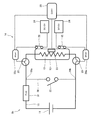
- FIG. 2 is a circuit diagram of the heating unit.
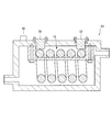
- FIG. 3 is a cross-sectional view showing a part of the heating unit.
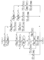
- FIG. 4 is a flowchart illustrating a method for controlling the heater unit.
- FIG. 1 is a schematic configuration diagram of a vehicle air conditioner 1 according to the present embodiment.
- vehicle air conditioner 1 mounted in a hybrid vehicle or an electric vehicle is demonstrated, it is not restricted to this.
- the vehicle air conditioner 1 includes a cooler unit 4 that cools (dehumidifies) air flowing through the air passage 2 by the blower 3, a heater unit 5 that warms the air, and a controller 25.
- the cooler unit 4 includes a compressor 4a that compresses and circulates a refrigerant, a condenser 4b that cools the compressed refrigerant, an evaporator 4c that evaporates the compressed and cooled refrigerant, and an expansion valve 4d that injects the refrigerant into the evaporator 4c. Prepare.
- the cooler unit 4 cools (dehumidifies) the air flowing through the air passage 2 when the refrigerant evaporates in the evaporator 4c.
- the heater unit 5 includes a water pump 5a that circulates cooling water (refrigerant), a heating unit 5b that warms the cooling water, a heater core 5c that warms the air flowing through the air passage 2 using the warmed cooling water, and removes air from the cooling water. And an air vent tank 5d.
- the flow volume of the air which flows into the heater core 5c can be adjusted with the mix door 5e.
- the heating unit 5b includes a DC power source 11, an electric heater 12 that is activated by a current supplied from the DC power source 11, a tank 13 that houses the electric heater 12, and a safety device 14 that supplies and blocks current to the electric heater 12.
- the DC power supply 11 is a high-power battery mounted on a hybrid vehicle or an electric vehicle.
- the output voltage of the DC power supply 11 is a strong electric power of 30 V or more, and is 350 V here.
- the current from the DC power supply 11 is supplied to the electric heater 12 through the supply line 15.
- an AC power source may be used as the power source.
- the DC power supply 11 supplies current to the compressor 4a and the like.
- Examples of the electric heater 12 include a sheathed heater that generates heat when energized, a PTC (Positive Temperature Coefficient) heater, and the like.
- the safety device 14 includes an IGBT (Insulated Gate Bipolar Transistor) 20 as a transistor provided in the supply line 15, a bimetal switch 22 that switches a control current for controlling the IGBT 20, and a control current (DC 12 V) to the IGBT 20. And a power supply device 24 to be supplied.
- IGBT Insulated Gate Bipolar Transistor
- the safety device 14 includes a short-circuit line 30 that can short-circuit the upstream and downstream of the electric heater 12 in the supply line 15, a power fuse 31 provided in the supply line 15 between the DC power supply 11 and the short-circuit line 30, And a bimetal switch 32 provided in the short-circuit line 30.
- the IGBT 20 interrupts the current supplied to the electric heater 12 when the control current is interrupted, and energizes the current supplied to the electric heater 12 when the control current is energized.
- the IGBT 20 is provided in the supply line 15 near the electric heater 12 as compared with the position where the short-circuit line 30 is short-circuited. When the short-circuit line 30 is short-circuited, the current from the DC power supply 11 does not flow through the IGBT 20. Thereby, IGBT20 is protected from the heavy current when the short circuit line 30 short-circuits.
- a pair of IGBTs 20 are provided upstream and downstream of the electric heater 12. Specifically, one IGBT 20 is provided downstream of the contact with one end 30 a of the short-circuit line 30 and upstream of the electric heater 12 in the current flow direction of the supply line 15, and the other IGBT 20 is connected to the electric heater 12. Provided downstream and upstream of the contact point with the other end 30 b of the short-circuit line 30.
- the IGBT 20 allows a current flow in the supply line 15 when the control current is energized.
- the controller 25 instructs the driver 20 a to cut off the control current from the power supply device 24 based on an electrical signal from the water temperature sensor 23, or the control current is cut off by the bimetal switch 22. If this occurs, the function is stopped and the current flow in the supply line 15 is interrupted.
- the IGBT 20 is disposed so as to be in contact with the tank 13 as shown in FIG. 3, for example, and is cooled by cooling water circulated by the water pump 5a.
- FIG. 3 is a schematic cross-sectional view of the electric heater 12 and the tank 13. Note that the IGBT 20 is not limited to the position in FIG. 3 and may be arranged so as to be cooled by the cooling water.
- the bimetal switch 22 is a normally closed type that is switched to an energized state in a normal state.
- the bimetal switch 22 is a low-power-side bimetal switch that allows a smaller current to flow compared to the bimetal switch 32 when switched to an energized state. As shown in FIG. 3, the bimetal switch 22 is in contact with the electric heater 12 so that heat can be transferred.
- the bimetal switch 22 cuts off the control current when the temperature of the electric heater 12 reaches the first set temperature, and when the temperature of the electric heater 12 decreases to a second set temperature that is lower than the first set temperature. Energize the control current.
- a pair of bimetal switches 22 are provided, and are respectively interposed between the power supply device 24 and each IGBT 20.
- the first set temperature is set higher than the upper limit water temperature Tw_lim in the allowable temperature range of the cooling water in the tank 13. Thereby, the bimetal switch 22 is maintained in an energized state when the control of the IGBT 20 by the controller 25 is normally performed.
- the second set temperature is set to a temperature when the temperature of the cooling water in the tank 13 is sufficiently lowered after the bimetal switch 22 cuts off the control current.
- the short-circuit line 30 has one end 30 a connected downstream of the power fuse 31 and upstream of the electric heater 12 in the current flow direction of the supply line 15, and downstream of the electric heater 12 and of the DC power supply 11.
- the other end 30b is connected upstream.
- the short-circuit line 30 is a conductor having a very small resistance that connects between the one end 30 a and the other end 30 b connected to the supply line 15. In other words, when the short circuit line 30 short-circuits the upstream and downstream of the electric heater 12, the resistance of the short circuit line 30 is smaller than the resistance of the electric heater 12.
- the bimetal switch 32 is a normally open type that is switched to an open state in a normal state.
- the bimetal switch 32 is a high-power-side bimetal switch that flows a larger current than the bimetal switch 22 when switched to an energized state. As shown in FIG. 3, the bimetal switch 32 is in contact with the electric heater 12 so that heat can be transferred.
- the bimetal switch 32 is switched to an energized state when the temperature of the electric heater 12 reaches a third set temperature that is higher than the first set temperature.
- the short circuit line 30 is not short-circuited when the temperature of the electric heater 12 is lower than the third set temperature.
- the short-circuit line 30 is short-circuited when the temperature of the electric heater 12 reaches the third set temperature and the bimetal switch 32 is switched to the energized state.
- the third set temperature is the critical temperature of the bimetal of the bimetal switch 32.
- the third set temperature rises due to overshoot after the temperature of the electric heater 12 reaches the first set temperature and the bimetal switch 22 cuts off the control current to the IGBT 20 to turn off the supply line 15.
- the temperature is set higher than the maximum temperature. Therefore, when the bimetal switch 22 and the IGBT 20 are operating normally, the temperature of the electric heater 12 does not reach the third set temperature.
- the power fuse 31 is cut by a large current (overcurrent) that flows instantaneously when the short-circuit line 30 is short-circuited. Since the resistance of the short-circuit line 30 is extremely small, when the short-circuit line 30 is short-circuited, the power fuse 31 has a large current (overcurrent) larger than the current flowing in the electric heater 12 before the short-circuit line 30 is short-circuited. Flowing.
- the power fuse 31 is cut by the current supplied from the DC power supply 11 before the heat generation of a harness (not shown) for supplying the current exceeds the allowable temperature. This allowable temperature is set to a temperature that does not damage the parts constituting the harness.
- the controller 25 controls the water pump 5a, the driver 20a, and the like based on a signal from the water temperature sensor 23, and controls the cooler unit 4 and the heater unit 5.
- step S100 the controller 25 determines whether or not the fail flag is ON. The process proceeds to step S102 when the fail flag is ON, and proceeds to step S101 when the fail flag is OFF.
- step S101 the controller 25 determines whether or not a new failure has been detected. The process proceeds to step S102 when a new failure is detected, and proceeds to step S113 when a new failure is not detected.
- step S102 the controller 25 determines whether or not the failure of the failure is unrecoverable.
- the non-recoverable abnormality is an abnormality related to the driving of the IGBT 20, for example, an IGBT function abnormality in which the input signal and the driving signal of the IGBT 20 do not match, or a driver abnormality in which the driver 20a for driving the IGBT 20 is broken.
- the process proceeds to step S103 if the failure is not irrecoverable abnormality, and proceeds to step S106 if the failure is not irrecoverable abnormality but is irrecoverable abnormality.
- the recoverable abnormality includes a voltage abnormality of the DC power supply 11, an IGBT temperature abnormality in which the temperature of the IGBT 20 is higher than the set temperature, a heater temperature abnormality in which the temperature of the electric heater 12 is higher than the set temperature, and the like.
- the heater temperature abnormality occurs, for example, when cooling water leaks or when the bimetal switch 22 is activated.
- step S103 the controller 25 turns on the fail flag.
- step S104 the controller 25 turns off the electric heater 12, prohibits the electric heater 12 from turning on, and prohibits the electric heater 12 from heating the cooling water. In the case where an abnormality that cannot be restored occurs, it is prohibited that the electric heater 12 is turned on until the location that caused the abnormality that cannot be restored is repaired.
- step S105 the controller 25 stops the water pump 5a.
- step S106 the controller 25 determines whether or not the recoverable abnormality has been canceled. Specifically, it is determined whether or not the recoverable abnormality causing the fail flag to be turned on has been canceled. The process proceeds to step S107 when the recoverable abnormality is canceled and proceeds to step S110 when the recoverable abnormality is not canceled.
- step S107 the controller 25 determines whether the function of the heater unit 5 is normal.
- step S106 it is determined whether or not the recoverable abnormality that caused the fail flag to be turned on, but here it is determined whether or not any other recoverable abnormality has occurred. The process proceeds to step S108 if no other recoverable abnormality has occurred and the function of the heater unit 5 is normal, and proceeds to step 110 if the function of the heater unit 5 is not normal.
- step S108 the controller 25 turns off the fail flag.
- step S109 the controller 25 continues to drive the water pump 5a.
- step S110 the controller 25 turns on the fail flag.
- step S111 the controller 25 turns off the electric heater 12, prohibits the electric heater 12 from turning on, and prohibits the electric heater 12 from heating the cooling water.
- the electric heater 12 cannot be turned on while the fail flag is ON, but unlike the step S104, the electric heater 12 can be turned ON when the fail flag is turned off. .
- step S112 the controller 25 continues to drive the water pump 5a.
- a recoverable abnormality for example, the temperature of the IGBT 20 may be high, and it is necessary to cool the IGBT 20 or the like. Therefore, when a recoverable abnormality occurs and the function of the heater unit 5 is not normal, the driving of the water pump 5a is continued and, for example, the IGBT 20 is cooled with cooling water so that the recoverable abnormality is canceled. .
- step S113 the controller 25 determines whether the signal of the water temperature sensor 23 is normal. Specifically, it is determined whether the value obtained by A / D conversion of the temperature Tw of the cooling water detected by the water temperature sensor 23 does not move from the “open” or “close” state, and the A / D converted value is “open”. ”Or“ close ”, if it does not move, it is determined that it is not normal.
- the process proceeds to step S114 when the signal of the water temperature sensor 23 is normal, and proceeds to step S119 when the signal of the water temperature sensor 23 is not normal.
- step S114 the controller 25 determines whether or not the water pump 5a is operating normally. Specifically, the controller 25 determines whether or not a drive signal is output from the water pump 5a, and determines that the drive signal is normal when the drive signal is output. The process proceeds to step S116 when the water pump 5a is normally driven, and proceeds to step S115 when the water pump 5a is not normally driven.
- step S115 the controller 25 stops driving the water pump 5a.
- step S116 the controller 25 determines whether the temperature Tw of the cooling water has increased since the electric heater 12 is turned off based on the signal from the water temperature sensor 23. The process proceeds to step S117 when the cooling water temperature Tw has increased, and proceeds to step S118 when the cooling water temperature Tw has not increased. Even when the electric heater 12 is ON, the process proceeds to step S118.
- step S117 the controller 25 turns on the fail flag. Note that this failure is an abnormality that cannot be restored. If the temperature Tw of the cooling water rises after the electric heater 12 is turned off, there is a possibility that an abnormality has occurred in the electric heater 12, the driver 20a, and the IGBT 20. For this reason, in the present embodiment, this failure is regarded as an unrecoverable abnormality, and the electric heater 12 is prohibited from being turned on.
- step S118 the controller 25 determines whether the temperature Tw of the cooling water is lower than the upper limit water temperature Tw_lim in the allowable temperature range. The process proceeds to step S120 when the temperature Tw is lower than the upper limit water temperature Tw_lim, and proceeds to step S119 when the temperature Tw is equal to or higher than the upper limit water temperature Tw_lim.
- step S119 the controller 25 turns off the electric heater 12.
- step S120 the controller 25 warms the cooling water by the electric heater 12 so that the air warmed by the heater core 5c becomes a desired temperature.
- step S121 the controller 25 continues to drive the water pump 5a.
- the recoverable abnormality includes that at least one of the temperature of the IGBT 20 or the temperature of the electric heater 12 is higher than each set temperature.
- the water pump 5a is driven. While continuing, heating by the electric heater 12 is prohibited. Thereby, the cooling water is circulated by the water pump 5a, the IGBT 20 and the electric heater 12 are cooled, and the recoverable abnormality can be released early.
- a non-recoverable abnormality it is determined whether a non-recoverable abnormality has occurred. If a non-recoverable abnormality has not occurred, it is determined whether a recoverable abnormality has occurred. When the unrecoverable abnormality has occurred, heating by the electric heater 12 is prohibited even when the recoverable abnormality has occurred and is canceled. Thereby, the further abnormality generation of the heater unit 5 can be suppressed.
- the electric heater 12 is turned on after confirming that the heater unit 5 operates normally. Thus, it is possible to suppress the electric heater 12 from being turned off immediately after being turned on.
Landscapes
- Engineering & Computer Science (AREA)
- Physics & Mathematics (AREA)
- Thermal Sciences (AREA)
- Mechanical Engineering (AREA)
- General Engineering & Computer Science (AREA)
- Chemical & Material Sciences (AREA)
- Combustion & Propulsion (AREA)
- Air-Conditioning For Vehicles (AREA)
- Hybrid Electric Vehicles (AREA)
Priority Applications (3)
| Application Number | Priority Date | Filing Date | Title |
|---|---|---|---|
| CN201480067443.0A CN105813869B (zh) | 2013-12-09 | 2014-11-04 | 车辆空调用安全装置及其控制方法 |
| US15/102,758 US10518608B2 (en) | 2013-12-09 | 2014-11-04 | Vehicle air-conditioner safety device, and control method thereof |
| EP14869547.1A EP3081411B1 (en) | 2013-12-09 | 2014-11-04 | Vehicle air-conditioning safety device, and method of controlling same |
Applications Claiming Priority (2)
| Application Number | Priority Date | Filing Date | Title |
|---|---|---|---|
| JP2013254265A JP6383536B2 (ja) | 2013-12-09 | 2013-12-09 | 車両空調用安全装置、及びその制御方法 |
| JP2013-254265 | 2013-12-09 |
Publications (1)
| Publication Number | Publication Date |
|---|---|
| WO2015087641A1 true WO2015087641A1 (ja) | 2015-06-18 |
Family
ID=53370956
Family Applications (1)
| Application Number | Title | Priority Date | Filing Date |
|---|---|---|---|
| PCT/JP2014/079266 Ceased WO2015087641A1 (ja) | 2013-12-09 | 2014-11-04 | 車両空調用安全装置、及びその制御方法 |
Country Status (5)
| Country | Link |
|---|---|
| US (1) | US10518608B2 (enExample) |
| EP (1) | EP3081411B1 (enExample) |
| JP (1) | JP6383536B2 (enExample) |
| CN (1) | CN105813869B (enExample) |
| WO (1) | WO2015087641A1 (enExample) |
Cited By (1)
| Publication number | Priority date | Publication date | Assignee | Title |
|---|---|---|---|---|
| JP2020150659A (ja) * | 2019-03-13 | 2020-09-17 | トヨタ自動車株式会社 | 電力機器の制御装置 |
Families Citing this family (5)
| Publication number | Priority date | Publication date | Assignee | Title |
|---|---|---|---|---|
| DE102013214554A1 (de) * | 2013-07-25 | 2015-01-29 | Bayerische Motoren Werke Aktiengesellschaft | Verfahren zum Heizen des Innenraums eines Fahrzeugs |
| JP6236323B2 (ja) * | 2014-01-21 | 2017-11-22 | カルソニックカンセイ株式会社 | 液体加熱装置 |
| JP6609853B2 (ja) * | 2016-12-27 | 2019-11-27 | 本田技研工業株式会社 | 車両の空調ユニット取付部構造 |
| CN207265713U (zh) * | 2017-07-28 | 2018-04-20 | 特斯拉公司 | 具有热保护的充电系统 |
| CN114670603B (zh) * | 2022-01-27 | 2024-06-18 | 北京新能源汽车股份有限公司 | 一种基于多传感器的加热器防干烧控制方法及装置 |
Citations (6)
| Publication number | Priority date | Publication date | Assignee | Title |
|---|---|---|---|---|
| JPH10287123A (ja) * | 1997-02-17 | 1998-10-27 | Matsushita Electric Ind Co Ltd | 自動車用空調制御装置 |
| JPH10299561A (ja) * | 1997-04-23 | 1998-11-10 | Denso Corp | 酸素センサのヒータ制御装置 |
| JP2007218447A (ja) | 2006-02-14 | 2007-08-30 | Matsushita Electric Ind Co Ltd | 空気調和機 |
| JP2013203254A (ja) * | 2012-03-28 | 2013-10-07 | Daihatsu Motor Co Ltd | 電気自動車用空調システム |
| JP2013220708A (ja) * | 2012-04-16 | 2013-10-28 | Mitsubishi Heavy Ind Ltd | 熱媒体加熱装置およびそれを備えた車両用空調装置 |
| JP2013230021A (ja) * | 2012-04-26 | 2013-11-07 | Calsonic Kansei Corp | 車両用安全装置 |
Family Cites Families (40)
| Publication number | Priority date | Publication date | Assignee | Title |
|---|---|---|---|---|
| US4091266A (en) * | 1975-04-08 | 1978-05-23 | Matsushita Electric Industrial Co., Ltd. | Electrical circuit for controlling a temperature of a heating element |
| US4926025A (en) * | 1989-03-06 | 1990-05-15 | Nartron Corporation | Electrically heated seat resistive heating element energization system |
| US4866559A (en) * | 1988-07-26 | 1989-09-12 | Texas Instruments Incorporated | Solid state circuit protector |
| JPH0573157A (ja) * | 1991-09-11 | 1993-03-26 | Kyocera Corp | 電力素子通電回路の故障判別装置 |
| DE19524260C5 (de) * | 1995-07-04 | 2005-11-17 | J. Eberspächer GmbH & Co. KG | Heizgerät, insbesondere zur Innenraumbeheizung eines Kraftfahrzeuges |
| JPH1071844A (ja) * | 1996-08-30 | 1998-03-17 | Matsushita Electric Ind Co Ltd | 自動車用給湯装置 |
| JP3369881B2 (ja) * | 1996-12-04 | 2003-01-20 | 松下電器産業株式会社 | 電気自動車用温水装置の保護装置 |
| JP3390638B2 (ja) * | 1997-09-03 | 2003-03-24 | 松下電器産業株式会社 | 自動車用空調制御装置 |
| US6262400B1 (en) * | 2000-10-03 | 2001-07-17 | Delphi Technologies, Inc. | Control method for a resistance heater in a vehicle heating system |
| JP2003019964A (ja) * | 2001-07-09 | 2003-01-21 | Yazaki Corp | ステアリングヒーター |
| JP2003088100A (ja) * | 2001-09-13 | 2003-03-20 | Tdk Corp | スイッチング電源装置 |
| JP2003125588A (ja) * | 2001-10-12 | 2003-04-25 | Mitsubishi Electric Corp | 電力変換装置 |
| US6627851B2 (en) * | 2001-12-07 | 2003-09-30 | Delphi Technologies, Inc. | Power control method for a motor vehicle electric window heater |
| JP2005255085A (ja) * | 2004-03-15 | 2005-09-22 | Sanyo Electric Co Ltd | 車両用空調装置 |
| US8064233B2 (en) * | 2004-08-19 | 2011-11-22 | Kokusai Electric Semiconductor Service Inc. | Power supply regulating apparatus, semiconductor manufacturing apparatus, method for controlling power to heater, and method for manufacturing semiconductor device |
| US6998584B1 (en) * | 2004-09-03 | 2006-02-14 | Caterpillar Inc. | System for output power control on electric heater drive |
| JP4840159B2 (ja) * | 2006-06-29 | 2011-12-21 | 株式会社デンソー | 負荷駆動制御装置および負荷駆動制御システム |
| JP4544244B2 (ja) * | 2006-12-22 | 2010-09-15 | パナソニック株式会社 | 暖房便座とそれを搭載したトイレ装置 |
| KR100974947B1 (ko) * | 2007-07-05 | 2010-08-10 | 권기병 | 비 노출형 데크클립 및 이를 이용한 목재패널 고정구조 |
| KR100905417B1 (ko) * | 2007-10-17 | 2009-07-02 | 신봉섭 | 히터전원 제어용 스위칭소자 고장시 전열기기의과열방지장치 |
| JP5146155B2 (ja) * | 2008-06-30 | 2013-02-20 | 株式会社デンソー | 電気ヒータ装置 |
| CN102150338B (zh) * | 2008-09-08 | 2015-05-13 | 三菱电机株式会社 | 过电流检测电路、逆变器以及过电流检测电路的调整方法 |
| EP2189733B1 (en) * | 2008-11-19 | 2016-06-01 | Mahle Behr France Rouffach S.A.S | Heater Controller and method for operating a heater controller |
| KR101210097B1 (ko) * | 2010-09-09 | 2012-12-07 | 기아자동차주식회사 | 공조 장치의 제어 방법 |
| US8788223B2 (en) * | 2010-10-29 | 2014-07-22 | GM Global Technology Operations LLC | Comprehensive method of electrical fluid heating system fault detection and handling |
| FR2967093B1 (fr) * | 2010-11-09 | 2012-11-16 | Valeo Systemes Thermiques | Dispositif et procede de commande d'un radiateur electrique d'un systeme de ventilation, chauffage et/ou climatisation automobile |
| JP5218526B2 (ja) * | 2010-11-11 | 2013-06-26 | トヨタ自動車株式会社 | 水温センサ異常判定装置 |
| DE102011009672A1 (de) * | 2011-01-28 | 2012-08-02 | Webasto Ag | Elektrische Heizung, Fahrzeug mit elektrischer Heizung sowie Verfahren zum Steuern einer elektrischen Heizung |
| WO2012147308A1 (ja) * | 2011-04-27 | 2012-11-01 | パナソニック株式会社 | シートヒータ |
| JP5827535B2 (ja) * | 2011-10-12 | 2015-12-02 | サンデンホールディングス株式会社 | 車載暖房用ヒータの制御装置 |
| KR101977837B1 (ko) * | 2011-11-25 | 2019-05-13 | 삼성전자주식회사 | 전원 공급 장치 및 그 제어 방법 |
| DE102012200570A1 (de) * | 2012-01-16 | 2013-07-18 | Webasto Ag | Elektrische Heizung |
| GB2499253B (en) * | 2012-02-13 | 2015-09-30 | Jaguar Land Rover Ltd | Heater and method of operation therefor |
| DE102012202379A1 (de) * | 2012-02-16 | 2015-08-13 | Webasto Ag | Fahrzeugheizung und Verfahren zur Überwachung einer Fahrzeugheizung |
| KR101444593B1 (ko) | 2012-04-26 | 2014-09-24 | 칼소닉 칸세이 가부시끼가이샤 | 차량용 안전 장치 |
| JP5851930B2 (ja) * | 2012-05-10 | 2016-02-03 | サンデンホールディングス株式会社 | 加熱装置 |
| JP6058466B2 (ja) * | 2012-06-07 | 2017-01-11 | カルソニックカンセイ株式会社 | 車両用電気ヒータ装置 |
| JP6396041B2 (ja) * | 2014-03-11 | 2018-09-26 | 三菱重工サーマルシステムズ株式会社 | 車両及び故障検知方法 |
| KR101551088B1 (ko) * | 2014-05-09 | 2015-09-07 | 현대자동차주식회사 | 배터리 승온 시스템 및 릴레이 고장 검출 장치 및 그 방법 |
| JP6539116B2 (ja) * | 2015-05-29 | 2019-07-03 | サンデン・オートモーティブクライメイトシステム株式会社 | 車両用空気調和装置 |
-
2013
- 2013-12-09 JP JP2013254265A patent/JP6383536B2/ja active Active
-
2014
- 2014-11-04 WO PCT/JP2014/079266 patent/WO2015087641A1/ja not_active Ceased
- 2014-11-04 CN CN201480067443.0A patent/CN105813869B/zh active Active
- 2014-11-04 EP EP14869547.1A patent/EP3081411B1/en active Active
- 2014-11-04 US US15/102,758 patent/US10518608B2/en active Active
Patent Citations (6)
| Publication number | Priority date | Publication date | Assignee | Title |
|---|---|---|---|---|
| JPH10287123A (ja) * | 1997-02-17 | 1998-10-27 | Matsushita Electric Ind Co Ltd | 自動車用空調制御装置 |
| JPH10299561A (ja) * | 1997-04-23 | 1998-11-10 | Denso Corp | 酸素センサのヒータ制御装置 |
| JP2007218447A (ja) | 2006-02-14 | 2007-08-30 | Matsushita Electric Ind Co Ltd | 空気調和機 |
| JP2013203254A (ja) * | 2012-03-28 | 2013-10-07 | Daihatsu Motor Co Ltd | 電気自動車用空調システム |
| JP2013220708A (ja) * | 2012-04-16 | 2013-10-28 | Mitsubishi Heavy Ind Ltd | 熱媒体加熱装置およびそれを備えた車両用空調装置 |
| JP2013230021A (ja) * | 2012-04-26 | 2013-11-07 | Calsonic Kansei Corp | 車両用安全装置 |
Non-Patent Citations (1)
| Title |
|---|
| See also references of EP3081411A4 |
Cited By (1)
| Publication number | Priority date | Publication date | Assignee | Title |
|---|---|---|---|---|
| JP2020150659A (ja) * | 2019-03-13 | 2020-09-17 | トヨタ自動車株式会社 | 電力機器の制御装置 |
Also Published As
| Publication number | Publication date |
|---|---|
| CN105813869A (zh) | 2016-07-27 |
| CN105813869B (zh) | 2018-12-18 |
| EP3081411A4 (en) | 2017-03-29 |
| EP3081411A1 (en) | 2016-10-19 |
| US10518608B2 (en) | 2019-12-31 |
| JP6383536B2 (ja) | 2018-08-29 |
| EP3081411B1 (en) | 2018-08-01 |
| JP2015112917A (ja) | 2015-06-22 |
| US20160318375A1 (en) | 2016-11-03 |
Similar Documents
| Publication | Publication Date | Title |
|---|---|---|
| JP6383536B2 (ja) | 車両空調用安全装置、及びその制御方法 | |
| KR101444593B1 (ko) | 차량용 안전 장치 | |
| US7782584B2 (en) | Load drive controller and control system | |
| KR102711911B1 (ko) | 방전 장치, 전기 유닛, 및 방전 방법 | |
| JP5114599B1 (ja) | 車両用安全装置 | |
| JP5146155B2 (ja) | 電気ヒータ装置 | |
| JP5960458B2 (ja) | 車両用空調装置 | |
| JP6654974B2 (ja) | 温度制御装置 | |
| CN115891863B (zh) | 一种车辆高压回路故障保护控制方法及系统 | |
| JP6239912B2 (ja) | 温度制御装置、温度制御方法 | |
| WO2015111279A1 (ja) | 液体加熱装置 | |
| JP6105276B2 (ja) | 車両用安全装置 | |
| JP5795822B2 (ja) | 温水加熱装置 | |
| KR101475793B1 (ko) | 전기자동차용 공조장치 | |
| JP6498045B2 (ja) | 車両用加熱装置 | |
| JP2020072010A (ja) | 電気ヒータ装置 | |
| JP2013257963A (ja) | 安全装置 | |
| JP2017019413A (ja) | 昇温システム | |
| JP2015207502A (ja) | 車両用液体加熱装置 | |
| JP2002321521A (ja) | 電気負荷制御装置および車両用空調装置 | |
| CN106553499B (zh) | 一种车辆空调系统电加热的供电系统及方法 | |
| KR20050110964A (ko) | 차량 공조장치용 피티씨 보조 히터코어의 제어방법 | |
| JPH04351491A (ja) | モータ制御装置 | |
| KR20130057657A (ko) | 전기자동차용 공조장치 |
Legal Events
| Date | Code | Title | Description |
|---|---|---|---|
| 121 | Ep: the epo has been informed by wipo that ep was designated in this application |
Ref document number: 14869547 Country of ref document: EP Kind code of ref document: A1 |
|
| WWE | Wipo information: entry into national phase |
Ref document number: 15102758 Country of ref document: US |
|
| NENP | Non-entry into the national phase |
Ref country code: DE |
|
| REEP | Request for entry into the european phase |
Ref document number: 2014869547 Country of ref document: EP |
|
| WWE | Wipo information: entry into national phase |
Ref document number: 2014869547 Country of ref document: EP |