WO2015060154A1 - 機械加工装置及び被加工物の機械加工方法 - Google Patents
機械加工装置及び被加工物の機械加工方法 Download PDFInfo
- Publication number
- WO2015060154A1 WO2015060154A1 PCT/JP2014/077295 JP2014077295W WO2015060154A1 WO 2015060154 A1 WO2015060154 A1 WO 2015060154A1 JP 2014077295 W JP2014077295 W JP 2014077295W WO 2015060154 A1 WO2015060154 A1 WO 2015060154A1
- Authority
- WO
- WIPO (PCT)
- Prior art keywords
- machining
- waste
- workpiece
- machine tool
- air
- Prior art date
Links
Images


Classifications
-
- B—PERFORMING OPERATIONS; TRANSPORTING
- B23—MACHINE TOOLS; METAL-WORKING NOT OTHERWISE PROVIDED FOR
- B23Q—DETAILS, COMPONENTS, OR ACCESSORIES FOR MACHINE TOOLS, e.g. ARRANGEMENTS FOR COPYING OR CONTROLLING; MACHINE TOOLS IN GENERAL CHARACTERISED BY THE CONSTRUCTION OF PARTICULAR DETAILS OR COMPONENTS; COMBINATIONS OR ASSOCIATIONS OF METAL-WORKING MACHINES, NOT DIRECTED TO A PARTICULAR RESULT
- B23Q11/00—Accessories fitted to machine tools for keeping tools or parts of the machine in good working condition or for cooling work; Safety devices specially combined with or arranged in, or specially adapted for use in connection with, machine tools
- B23Q11/0042—Devices for removing chips
- B23Q11/006—Devices for removing chips by sucking and blowing simultaneously
-
- B—PERFORMING OPERATIONS; TRANSPORTING
- B23—MACHINE TOOLS; METAL-WORKING NOT OTHERWISE PROVIDED FOR
- B23C—MILLING
- B23C3/00—Milling particular work; Special milling operations; Machines therefor
- B23C3/28—Grooving workpieces
-
- B—PERFORMING OPERATIONS; TRANSPORTING
- B23—MACHINE TOOLS; METAL-WORKING NOT OTHERWISE PROVIDED FOR
- B23Q—DETAILS, COMPONENTS, OR ACCESSORIES FOR MACHINE TOOLS, e.g. ARRANGEMENTS FOR COPYING OR CONTROLLING; MACHINE TOOLS IN GENERAL CHARACTERISED BY THE CONSTRUCTION OF PARTICULAR DETAILS OR COMPONENTS; COMBINATIONS OR ASSOCIATIONS OF METAL-WORKING MACHINES, NOT DIRECTED TO A PARTICULAR RESULT
- B23Q11/00—Accessories fitted to machine tools for keeping tools or parts of the machine in good working condition or for cooling work; Safety devices specially combined with or arranged in, or specially adapted for use in connection with, machine tools
- B23Q11/08—Protective coverings for parts of machine tools; Splash guards
- B23Q11/0816—Foldable coverings, e.g. bellows
-
- B—PERFORMING OPERATIONS; TRANSPORTING
- B23—MACHINE TOOLS; METAL-WORKING NOT OTHERWISE PROVIDED FOR
- B23C—MILLING
- B23C2215/00—Details of workpieces
- B23C2215/08—Automotive parts
-
- B—PERFORMING OPERATIONS; TRANSPORTING
- B23—MACHINE TOOLS; METAL-WORKING NOT OTHERWISE PROVIDED FOR
- B23C—MILLING
- B23C2220/00—Details of milling processes
- B23C2220/64—Using an endmill, i.e. a shaft milling cutter, to generate profile of a crankshaft or camshaft
-
- B—PERFORMING OPERATIONS; TRANSPORTING
- B23—MACHINE TOOLS; METAL-WORKING NOT OTHERWISE PROVIDED FOR
- B23C—MILLING
- B23C2230/00—Details of chip evacuation
- B23C2230/08—Using suction
-
- Y—GENERAL TAGGING OF NEW TECHNOLOGICAL DEVELOPMENTS; GENERAL TAGGING OF CROSS-SECTIONAL TECHNOLOGIES SPANNING OVER SEVERAL SECTIONS OF THE IPC; TECHNICAL SUBJECTS COVERED BY FORMER USPC CROSS-REFERENCE ART COLLECTIONS [XRACs] AND DIGESTS
- Y02—TECHNOLOGIES OR APPLICATIONS FOR MITIGATION OR ADAPTATION AGAINST CLIMATE CHANGE
- Y02P—CLIMATE CHANGE MITIGATION TECHNOLOGIES IN THE PRODUCTION OR PROCESSING OF GOODS
- Y02P70/00—Climate change mitigation technologies in the production process for final industrial or consumer products
- Y02P70/10—Greenhouse gas [GHG] capture, material saving, heat recovery or other energy efficient measures, e.g. motor control, characterised by manufacturing processes, e.g. for rolling metal or metal working
Definitions
- the present invention relates to a machining apparatus and a machining method for a workpiece using the machining apparatus.
- the present invention relates to a machining device that has a long tool life in a machining device and has high machining accuracy and measurement accuracy for a workpiece, and a machining method for a workpiece using the machining device.
- the airbag tear line forming device 200 includes a tear line formation receiving base for setting the outer skin 220 that forms the tear line 220a, and a tear line 220a.
- a cutting tool 210 including a spindle 209, a vertical movement plate 207 including a solenoid 208 for reciprocating a predetermined distance (0.5 to 3 mm) through the sliding mechanism 206, and the vertical movement plate 207 And a processing block 205 that allows the moving plate 207 to move in the directions of three orthogonal axes.
- a dust collection attachment for reliably collecting dust generated at the time of cutting or the like at low cost has been proposed (see Patent Document 2). More specifically, as shown in FIG. 10, a cylindrical cover portion 502 that has a plurality of bellows portions 502b and 502d, surrounds the hammer 510b of the chipping hammer 510, and becomes negative pressure by suction of air,
- the dust collection attachment 501 is characterized in that an intake pipe portion 503 for sucking and collecting dust inside the cover portion 502 is connected between the plurality of bellows portions 502b and 502d.
- the applicant of the present invention has already proposed a machining apparatus provided with a waste collection device for collecting waste generated by a predetermined machining process (see Patent Document 3). More specifically, the waste collection device is provided in the middle of the transfer path for transferring the waste using an air flow, and supplies a predetermined amount of moisture to the waste. Disposal comprising: a moisture supply device for performing antistatic treatment; a cyclone for separating and processing waste in an antistatic state; and a recovery tank for collecting waste separated by the cyclone. It is a machining device provided with an object recovery device.
- Patent No. 4382429 (Claims, FIG. 4 etc.) JP 2004-306212 (Claims, FIG. 2 etc.) International Publication No. 2011-121853 (Claims, FIG. 1 etc.)
- the airbag tear line forming apparatus 200 described in Patent Document 1 does not include a collection device for waste generated by the cutting process, and does not consider any waste remaining on the tear line. It was. In other words, when measuring the depth of a tear line (breaking groove) using an optical measuring device such as a laser displacement meter, the depth of the tear line is accurately measured because wastes interfere with the measurement accuracy. There was a problem that it was difficult. In particular, it is a fact that while cutting, the depth of the tear line is measured quickly and accurately due to the effects of waste generated in large quantities, and the cutting state is adjusted while feeding back the value. It was difficult.
- the airbag tear line forming apparatus 200 described in Patent Document 1 is provided with a solenoid 208 for reciprocating a predetermined distance (about 0.5 to 3 mm) for the cutting tool. Even though the portion can be provided intermittently, the continuous formation has a problem that the required time becomes longer and the manufacturing cost becomes higher.
- the dust collection attachment 501 described in Patent Document 2 is intended to collect dust generated by the hammer 510b, which is a machining device, it does not take into account a predetermined antistatic treatment. Even if a recovery tank or the like is provided, static electricity is generated and dust cannot be recovered efficiently. In particular, during the dry season in winter, a large amount of generated dust adheres to the inner wall of a cyclone, a recovery tank or the like due to static electricity, and it is difficult to take it out efficiently.
- the entire cylindrical cover portion 502 surrounding the hammer 510b has rubber bellows portions 502b and 502d, and is easily elastically deformed not only in the vertical direction but also in the horizontal direction. As a result, there was a problem that it was difficult to perform machining processing with high accuracy.
- the efficiency of collecting the waste of a predetermined size is very good, but the joule in the machine tool under the predetermined environment is excellent.
- the effect of heat generation was not taken into consideration. Therefore, when a machining apparatus is driven at a high speed for a long period of time and under a temperature condition where the environmental temperature exceeds 40 ° C., more significantly, 50 ° C., the machine tool is likely to deteriorate. It was observed. Further, when the machine tool is deteriorated, there is a problem that the machining accuracy for the workpiece is remarkably lowered.
- the average particle size is less than 100 ⁇ m, and more noticeably, fine particles of less than 0.1 to 10 ⁇ m, depending on the type of machining, it tends to remain on the work piece, resulting in measurement errors related to the machining depth. It was a factor that occurred.
- the inventor has intensively studied and is a machining device including a machine tool housed in a cylindrical object, and is provided with a scattering prevention member and a transfer path for the cylindrical object.
- the machining device can be used for a long time and the environmental temperature exceeds 40 ° C.
- the machine tool is not deteriorated even when it is driven at high speed under various temperature conditions, and it has been found that excellent machining accuracy and good measurement accuracy by the sensor are maintained, and the present invention has been completed. It is a thing. That is, the present invention provides a machining device having a long tool life in a machining device and high machining accuracy and measurement accuracy for the workpiece, and a workpiece machining method using the machining device. The purpose is to do.
- a machining apparatus that performs predetermined machining on a workpiece with a machine tool accommodated in the cylinder, and a predetermined amount is applied to a tip of the cylinder.
- a scattering prevention member that comes into contact with the workpiece without any gaps, and a transfer path for sucking the waste of the workpiece produced by the predetermined machining is provided on the side surface of the cylindrical object.
- a machining apparatus characterized in that an air blowing device for blowing air to at least a tip portion of a machine tool is provided at a symmetrical position on a side surface of a cylindrical object provided with a transfer path.
- the machining apparatus of the present invention when predetermined machining is performed by air (high-speed air) blown from the air blowing port of the air blowing device, Joule heat generated in the machine tool is efficiently generated. Can be removed. As a result, the life of the machine tool is not reduced and excellent machining accuracy is maintained even if it is driven at a high speed under a temperature condition where the ambient temperature exceeds 40 ° C. can do.
- the transfer path and the air blowing device are substantially symmetrical with respect to the center line (corresponding to the center line M2 of the machine tool) of the cylindrical object (for example, cylindrical When viewed from above with respect to the center line of the object, it means a range of 180 ° ⁇ 30 °.
- the height position of the transfer path is higher than the height position of the air outlet.
- the waste remaining in a predetermined machined portion can be blown upward by the high-speed air blown from the air blowout port, and the transfer route can be used. Can be more efficiently aspirated.
- the air pressure is preferably set to a value within the range of 500 to 50000 kPa (5 to 500 bar).
- the air pressure is considered in this way, the cooling effect of the machine tool by the high-speed air and the removability of the waste remaining in a predetermined machined place can be remarkably enhanced.
- an air outlet is provided at the tip of a syringe-like object extending from the outside to the inside of the cylindrical object, and the air outlet and the machine tool It is preferable that the distance between the tip portion is variable.
- the cooling effect of the machine tool by high-speed air and the removability of the waste remaining in the predetermined machined location can each be improved significantly.
- the cooling effect of the machine tool by the high-speed air and the removability of the waste remaining in the predetermined machined portion can be remarkably enhanced.
- the cylindrical object and the transfer path are composed of a titanium compound (including titanium metal) as a main component.
- a titanium compound including titanium metal
- the scattering prevention member is made of a resin containing an antistatic agent.
- the scattering prevention member is made of a resin containing an antistatic agent.
- the machine tool is attached to a robot arm that changes the plane position and the vertical position while driving the machine tool, and the machine tool is attached to the robot arm. It is preferable that a sensor for measuring the processing depth is attached.
- the robot arm as a driving device and a predetermined sensor (such as an optical sensor) are provided in this way, the handling of the machining apparatus is remarkably improved, and the predetermined machining process is performed with high accuracy at high speed. It can be performed.
- Another aspect of the present invention is a machining apparatus that performs predetermined machining on a workpiece with a machine tool housed in the cylinder, and the tip of the cylinder
- a scattering prevention member that comes into contact with the workpiece without any gap during the predetermined machining is provided, and transfer of sucking the waste of the workpiece produced by the predetermined machining to the side surface of the cylindrical object
- a machining apparatus is provided in which a path is provided and an air blowing device for blowing air to at least the tip of the machine tool is provided at a symmetrical position on the side surface of the cylindrical object provided with the transfer path.
- a machining method for a workpiece which includes the following steps (1) to (2).
- the high-speed air blown from the air blowout port of the air blowing device it is possible to blow away even the waste remaining in a predetermined machined location, particularly fine waste (foreign matter) of 100 ⁇ m or less,
- the accuracy of thickness measurement by the sensor can be remarkably increased, and the recovery efficiency using a cyclone or the like can be increased.
- the transfer path and the air blowing device are provided at symmetrical positions on the side surface of the cylindrical object with respect to the center position of the cylindrical object (coincident with the center line M2 of the machine tool), these This reduces the possibility of interference with the operation of the machine tool, and enables high-speed machining.
- the tip of the cylindrical object is provided with an anti-scattering member that comes into contact with the workpiece during the predetermined machining, it is possible to prevent waste from jumping out of the desired location. It is possible to contribute to making the pressure inside the cylindrical object negative.
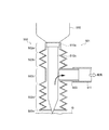
- FIG. 1 is a schematic view for explaining a machining apparatus according to the present invention.
- FIG. 2 is a schematic diagram for explaining a waste recovery apparatus connected to the machining apparatus of the present invention.
- FIG. 3 is a diagram provided to explain the relationship between the machining device of the present invention and the waste recovery device connected thereto.
- FIGS. 4A and 4B are diagrams provided for schematically explaining the operation of the machining apparatus including the cutting apparatus (end mill) and the cutting apparatus (ultrasonic cutter).
- FIGS. 5A and 5B are views for explaining an aspect of the airbag device.
- FIG. 6 is a diagram provided for explaining the outline of the airbag fracture groove forming apparatus.
- FIG. 7 is a diagram for explaining the state of the airbag substrate on which the tear line of the first embodiment is formed.
- FIG. 1 is a schematic view for explaining a machining apparatus according to the present invention.
- FIG. 2 is a schematic diagram for explaining a waste recovery apparatus connected to the machining apparatus of the present invention.
- FIG. 8A is a diagram for explaining the state of the airbag substrate on which the tear line of Example 1 is formed
- FIG. 8B is an air diagram on which the tear line of Comparative Example 1 is formed. It is a figure provided in order to demonstrate the state of a bag board
- FIG. 9 is a diagram provided for explaining a conventional airbag tear line forming apparatus.
- FIG. 10 is a diagram provided for explaining a conventional dust collection attachment.
- the first embodiment is a machining apparatus 12 that performs predetermined machining on a workpiece 15 by a machine tool 12 a housed in a cylindrical object 12 b.
- an anti-scattering member 12c that is in contact with the workpiece 15 without a gap during predetermined machining is provided at the tip of the cylindrical object 12b, and is produced on the side surface of the cylindrical object 12b by predetermined machining.
- the transfer path 14 for sucking the waste of the workpiece 15 is provided, and air is provided at least at the tip of the machine tool 12 at a symmetrical position on the side surface of the cylindrical object 12b on which the transfer path 14 is provided.
- the machining device 12 is provided with an air blowing device 12e for spraying air.
- FIG. 1 is a schematic view of the machining apparatus 12, and FIG. 2 is a schematic view showing the waste collection apparatus 10 connected to the transfer path 14 of the machining apparatus 12.
- FIG. 3 further shows the relationship between the machining device 12 and the waste collection device 10 connected thereto.
- symbol A represents a machine processing unit for performing a predetermined processing
- symbol B indicates a charging processing unit for performing a predetermined charging process on the waste
- symbol C indicates a recovery unit for recovering the waste.
- an airbag breaking groove is formed mainly for forming an airbag breaking groove (tear line) for an automobile interior member (airbag door member).
- the machining apparatus according to the first embodiment will be described by taking as an example the case of assuming an industrial apparatus.
- Type of machining device (1) As a type of the machining device (including a machine tool) 12 illustrated in FIG. 1 or FIG. 3, if it is a configuration that generates waste by performing a predetermined machining process, although not particularly limited, for example, at least one of a cutting device, a polishing device, a cutting device, a drilling device, or the like, or these machining devices and other mechanical devices, inspection devices, vapor deposition devices, and coating devices. Or a combination with a heating device or the like.
- examples of the cutting device include an end mill, a vibration cutting device (including an ultrasonic vibration cutting device, an elliptical vibration cutting device, and the like), a rotary shaft cutting device, and the like.
- a solid end mill having a bottom blade at the tip and a side blade at the side is optimal as a cutting tool.
- examples of the polishing apparatus include a bite, a grinder, a blast, and a file.
- examples of the drilling device include a drill (including a high-frequency ultrasonic drill), a reamer, and a tap.
- the machining device is an airbag breaking groove forming device, as shown in FIGS. 4A to 4B, an end mill 12 as a cutting device, an ultrasonic cutter 11 as a cutting device, By providing each, both or one of them can be used according to the type of workpiece or the purpose of use.
- an airbag breaking groove having a rectangular cross section can be continuously formed on the workpiece 15 using the end mill 12.
- the ultrasonic cutter 11 is attached to the bottom of the airbag break groove having a rectangular cross section formed by the end mill 12 indirectly or directly to the workpiece 15. It is also possible to provide a plurality of cutting points with a predetermined interval.
- FIG. 4A shows a state in which the end mill 12 is attached to the robot arm. More specifically, the end mill 12 performs a vertical motion or a rotational motion, that is, positioning in a so-called three-dimensional direction.
- Position control device 13 13a, 13b, 13c for performing is provided. Therefore, the end mill 12 is configured to be able to descend from a predetermined position to a position below the predetermined position by a cylinder 12d connected to the position control device 13 and the like, and a process for continuously forming an airbag breaking groove in the workpiece 15. State.
- the ultrasonic cutter 11 provided on the opposite side of the end mill 12 via the position control device 13 is configured to be movable to a position above a predetermined position so that the operation of the end mill 12 is not hindered. It is configured.
- FIG. 4B shows that the ultrasonic cutter 11 (11a, 11b, 11c) is lowered to a position below a predetermined position by the position control device 13, and the airbag 15 is broken against the workpiece 15.
- the ultrasonic cutter 11 is comprised including the front-end
- the end mill 12 is raised to a position above the predetermined position, and the operation of the ultrasonic cutter 11 is obstructed. It is configured not to.
- machining devices such as a cutting device, a polishing device, a cutting device, and a punching device in accordance with the form of the workpiece. That is, as shown in FIG. 5A, when the airbag door member 40 includes a single-layer base material 15 made of polypropylene resin (hard polypropylene resin), ABS resin, or the like, By using only the cutting device (end mill), it is possible to suck and remove the generated waste while forming the airbag breaking groove 15e substantially consisting of a continuous line.
- polypropylene resin hard polypropylene resin
- ABS resin or the like
- a laser displacement meter 13d (for example, manufactured by Keyence Corporation) is used as a sensor for the processing state (breaking groove depth, etc.) of the workpiece 15 as a base material.
- the air bag door member 40 including the base material 15 having the above can be manufactured very inexpensively and efficiently. And according to this invention, while providing a scattering prevention member and a transfer path
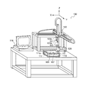
- the groove forming apparatus 100 includes a support base 111 on which an automobile interior member (airbag door member) is placed.
- a primary break line forming means 131 for forming a primary break line for example, a break groove having a predetermined width and a predetermined depth
- Secondary break line forming means 133 for forming a next break line for example, a slit line having a predetermined depth
- the machine blade detection means 167 and the 2nd process blade detection means 169 attached to these are each provided in the back side of the mounting surface 111a.
- the first machining blade detection means 167 and the second machining blade detection means 169 are usually optical measuring devices such as a laser displacement meter when measuring from the front side of the workpiece. When measuring from the back side of the workpiece, it is an electromagnetic induction type measuring device such as an eddy current type film pressure gauge.
- the airbag break groove forming apparatus 100 includes a control unit (computer control unit) for accurately performing positioning, processing operation, detection operation, and the like of various primary break line forming means and secondary break line forming means. 116).
- either one of the primary break line forming means and the secondary break line forming means may be used, or the primary break line forming means and the secondary break line
- a tertiary fracture line forming means may be further provided.
- the airbag break groove forming apparatus 100 includes a support base 111 on which an automobile interior member is placed and fixed when the airbag break groove is formed.
- the mounting surface 111a of the support base 111 is provided with a plurality of suction holes 117, and an automobile interior member placed on the mounting surface 111a is sucked and fixed through the suction holes 117.
- a suction device 118 is provided.
- As the suction device 118 for example, a vacuum pump or the like can be used. By providing such a suction device 118, even an interior member for an automobile having a complicated shape or an interior member for a large automobile can be easily fixed on the support base 111.
- At least one machine tool 12a is provided as the break line forming means.
- a machine tool for example, at least one of an end mill, a hot melt blade, an ultrasonic cutter, a laser cutter, and the like can be suitably used. That is, with these machine tools, Joule heat is efficiently removed by the air (high-speed air) blown from the air outlet of the air blowing device even if the temperature becomes high due to long-term use or the like. Because it can. As a result, the life of the machine tool is not reduced and excellent machining accuracy is maintained even if it is driven at a high speed under a temperature condition where the ambient temperature exceeds 40 ° C. Will be able to.
- waste remaining in a predetermined machined place by high-speed air blown from the air outlet of the air blowing device particularly fine waste (foreign matter) of 100 ⁇ m or less. It can be blown away. Therefore, it is possible to remarkably increase the accuracy of thickness measurement using a sensor, and to increase the collection efficiency using a cyclone or the like.
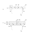
- the primary fracture line forming means 131 is a vehicle interior member (airbag door portion) made of only the hard workpiece 15, as shown in FIG.
- Processing means for forming an airbag breaking line 15d having a predetermined thickness (t1) that is partially cut from the back side of the workpiece 15 having a predetermined thickness (t2) but does not reach the surface side. Breaking line forming means).
- the predetermined thickness (t2) of the workpiece 15 is usually in the range of 1.0 to 2.5 mm, and the predetermined thickness (t1) of the remaining workpiece that does not reach the surface side is normally The value is in the range of 0.1 to 0.8 mm, more preferably in the range of 0.2 to 0.7 mm, and the value in the range of 0.3 to 0.6 mm. Is more preferable.
- the workpiece 15 has a three-layer structure including a hard base material 15'd, an intermediate layer (foamed layer) 15'e, and a skin 15'f.
- the primary break line is formed from the hard work piece 15'd side through the hard base material 15'd to a depth not reaching the skin 15'f. It is a processing means.
- the predetermined thickness (t3) of the remaining epidermis that does not reach the surface side is usually in the range of 0.1 to 0.8 mm, but may be a value in the range of 0.2 to 0.7 mm. More preferably, the value is in the range of 0.3 to 0.6 mm.
- an end mill, a heat fusion blade, an ultrasonic cutter, a laser cutter, etc. can be used conveniently.
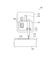
- the airbag fracture groove forming apparatus 100 shown in FIG. 6 allows a machine tool (sometimes referred to as a processing blade) 113 to enter through the primary fracture line to reach the skin 15′f.
- Secondary break line forming means 133 is provided as processing means for forming (thickness t3). Therefore, the machine tool (ultrasonic cutter or the like) 113 included in the secondary break line forming means 133 is formed in an elongated plate shape as a whole, and the machine tool (end mill or the like) included in the primary break line forming means 131 is used. It is made possible to enter the inside of the formed primary break line.
- the primary break line forming means 131 and the secondary break line forming means 133 are both fixed to a fixing portion 163 a of the break line forming means in the movement control robot 163. Therefore, when forming the primary break line, the movement control robot 163 operates to perform a predetermined cutting operation while positioning the hard base material 15 ′ by the primary break line forming means 133. Next, when forming the secondary break line, a predetermined cutting operation is performed in a state in which the skin 15'f can be cut by the secondary break line forming means 133.
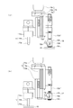
- a predetermined air blowing device 12e is provided at a predetermined place as a cooling means for the machining blade. This is because the Joule heat generated in the machine tool can be efficiently removed by the air B (high-speed air) blown from the air outlet 12f of the air blowing device 12e. As a result, even if it is driven at high speed under a temperature condition where the environmental temperature exceeds 40 ° C., the cooling effect is exhibited, and the life of the machine tool is not deteriorated and is excellent. Machining accuracy can be maintained.
- the air B blown from the air outlet 12f of the air blowing device 12e can blow away even the waste remaining in a predetermined machined portion, particularly fine waste (foreign matter) of 100 ⁇ m or less. it can. Therefore, it is possible to remarkably increase the measurement accuracy of the thickness and width of the processed portion by a laser displacement meter and the like, and further, it is possible to collect using a cyclone including fine waste, so that the collection efficiency can be further increased. .
- the air pressure at the air blowing port 12f is preferably set to a value in the range of 500 to 50000 kPa (5 to 500 bar). This is because, within the range of such air pressure, the cooling effect of the machine tool by high-speed air and the removability of the waste remaining in a predetermined machined portion can be remarkably enhanced. . More specifically, when the air pressure is less than 500 kPa, the cooling effect of the machine tool tends to be insufficient.
- the air pressure at the air outlet 12f is more preferably set to a value within the range of 800 to 30000 kPa, and further preferably set to a value within the range of 1000 to 15000 kPa.
- the air outlet 12f and the tip of the machine tool 12a are used.
- the cooling effect of the machine tool by the air B and the removability of the waste remaining in a predetermined machined location can be further enhanced.
- the distance from the surface of the workpiece 15 to the height position (L1) of the air blowing port 12f of the air blowing device 12e from the surface of the workpiece 15 is larger than the linear distance. It is preferable to increase the linear distance to the height position (L2, L4) of the transfer path 14. The reason for this is that if the air blowing device 12e is configured in consideration of the height positions (L1, L2, L4) as described above, the air B blown from the air blowing port 12f remains in a predetermined machined portion. This is because the waste can be intensively blown upward.
- the waste blown above is sucked from a suction port provided relatively above, and further, via a transfer path 14 including a pipe 14a that is obliquely upward and a vertical pipe 14b that follows the pipe 14a.
- a transfer path 14 including a pipe 14a that is obliquely upward and a vertical pipe 14b that follows the pipe 14a.
- the air B for cooling is sufficiently and efficiently applied to the tip position 12a ′ of the machine tool 12a, and not only the air pressure and the flow velocity are used to prevent the influence of the chuck 12d ′ that holds the machine tool. It is also preferable to consider the height position (L1) of the air outlet.
- the position (L3) of the chuck 12d ′ of the machine tool 12 from the surface of the workpiece 15 is higher than the height position (L1) of the air outlet 12f from the surface of the workpiece 15, and The position of the chuck 12d ′ of the machine tool 12 so as to fall between the lower limit height position (L2) of the transfer path 14 from the surface of the workpiece 15 and the upper limit height position (L4) of the transfer path 14 ( It is preferable to define L3).
- an angle ( ⁇ 3) at which the center imaginary line (M1) of the air blowing device 12e attached to the side surface of the cylindrical object 12b and the center imaginary line (M2) of the machine tool 12a intersect each other is A value within the range of 10 to 60 ° is preferable. This is because if the angle is less than 10 °, it is difficult to attach the air blowing device 12e to the side surface of the cylindrical object 12b. This is because it may become difficult and efficient to hit. On the other hand, if the angle exceeds 60 °, it is not only difficult to attach the air blowing device 12e to the side surface of the cylindrical object 12b, but the cooling air B is also sufficient and efficient. This is because it may be difficult to hit.
- the angle at which the center imaginary line (M1) of the air blowing device 12e and the center imaginary line (M2) of the machine tool 12a intersect is preferably set to a value in the range of 15 to 55 °, and preferably 20 to 45 °. More preferably, the value is within the range.
- intersect in FIG. As an example, a case of 65 ° is shown.
- such an angle is preferably set to a value in the range of 30 to 80 °, more preferably set to a value in the range of 35 to 75 °, and 45 to 70. More preferably, the value is within the range of °.
- the scattering prevention member is made of a resin containing an antistatic agent. This is because frictional charging in the scattering prevention member can be effectively prevented, and a phenomenon that fine waste easily adheres to the inner surface of the scattering prevention member can be effectively prevented.
- an accordion-shaped anti-scattering member is composed of olefin resin, polyester resin, polycarbonate resin, synthetic rubber, thermoplastic elastomer or the like as a main component.
- Antistatic agents such as carbon particles, carbon fibers, aramid fibers, metal particles, and semiconductor particles with respect to parts by weight have values in the range of 0.1 to 50 parts by weight. It is preferable to blend so as to have a value in the range of 1 to 40 parts by weight, and it is more preferable to blend so as to have a value in the range of 10 to 30 parts by weight.
- the depth of the groove to be formed is controlled by controlling the position of the blade edge by the machine tool 131a constituting a part of the primary fracture line forming means 131. That is, in order to adjust the thickness of the remaining part of the substrate, it is preferable to provide an optical measuring device (laser reflection type laser displacement meter or the like) for actually measuring the depth of the primary fracture line on time.
- an optical measuring device laser reflection type laser displacement meter or the like
- a first machining edge detection means 167 and a second machining edge detection means 169 for detecting the position of the cutting edge of the machine tool that constitutes a part of the secondary fracture line forming means 133 are provided below the support base 111. Each is preferably provided.
- the first processing blade detection unit 167 and the second processing blade detection unit 169 are arranged inside the support base 111 so that the presence / absence of a machine tool is detected at a specific detection position set in advance. It is configured. And as such 1st processing blade detection means 167 and 2nd processing blade detection means 169, for example, a metal detector is suitable, and when a metal machine tool passes a detection position by it, for example In addition, the presence or absence of a machine tool can be detected.
- the cutting edge state detection unit 129 is a unit for detecting the state of wear or damage of the cutting edge of the machine tool (machining blade). That is, the state of the cutting edge of the processing blade is measured, and when the state damaged by wear or the like is detected, the operation of the apparatus is stopped and the processing blade can be replaced. Therefore, the thickness of the remaining part of the airbag breaking groove to be formed can be adjusted with high accuracy.
- the cutting edge state detection means is configured using a laser displacement meter, an infrared measurement device, or the like, and detects the cutting edge state of the machining blade while maintaining the tip of the movement control robot 163 at a predetermined height.
- the constituent material of the machining apparatus is not particularly limited, but at least the cylindrical object and the transfer path are composed of a titanium compound (including titanium metal) as a main component. Preferably it is.
- a titanium compound including titanium metal
- the main drive unit of the machining apparatus is reduced in weight, the machining accuracy is remarkably improved, and the mechanical strength is dramatically increased. This is because the life of the machining apparatus can be significantly extended.
- the cylinder and the transfer path are made of a titanium compound, the chargeability is reduced, and furthermore, the processability is excellent, and therefore, the predetermined form can be easily configured by welding, for example. This is because it can.
- titanium compounds generally have a problem that they are expensive, but as long as the effects described above are obtained, they surpass such problems, and rather, since durability and corrosion resistance are significantly increased, a long-term viewpoint Therefore, it can be said that it is a relatively inexpensive material.
- aluminum, iron, and the like have been mainly used as the constituent material of the cylindrical object and the transfer path.
- workability weldingability
- iron it is difficult to reduce the weight, and there is a problem in corrosivity.
- the construction type of the work piece (sometimes simply referred to as a base material) is not particularly limited.
- a base material polyethylene resin, polypropylene resin, polystyrene resin, polyester resin , Synthetic resin such as polycarbonate resin, polyurethane resin, polyamide resin, polyvinyl chloride resin, polysulfone resin, gold, silver, copper, platinum, nickel, titanium, aluminum, zinc, iron, lead, cadmium, tungsten, indium, molybdenum, etc.
- Metals including alloys
- silver oxide copper oxide, silicon oxide, nickel oxide, titanium oxide, aluminum oxide, zinc oxide, iron oxide, lead oxide, cadmium oxide, tungsten oxide, indium oxide, molybdenum oxide, glass, ceramic Oxides such as hydroxides such as aluminum hydroxide, Examples thereof include three-dimensional molded products and films made of ceramic materials, and composites and mixtures thereof.
- the interior member for automobiles (airbag door member) 40 illustrated by Fig.5 (a) is comprised as a to-be-processed object.
- the waste generated from the workpiece by the machining process varies depending on the type and mode of the workpiece or the type and mode of the machining apparatus. , Cutting waste, abrasive powder, abrasive waste, perforated powder, perforated waste, and the like. Therefore, when an apparatus for forming an air bag fracture groove is assumed as the machining device, the waste generated from the workpiece is specifically a circular shape made of polypropylene resin, polyurethane resin, polyvinyl chloride resin, or the like. , Oval shapes, polygonal shapes, irregular shapes, ribbon shapes, and the like.
- the average particle size (equivalent circle diameter or equivalent sphere diameter) of the waste is set to a value within the range of 0.01 to 8 mm. Is preferred. The reason for this is that when the average particle size of such waste is less than 0.01 mm, the transportability in the transfer path is reduced, the antistatic properties due to the application of a predetermined amount of moisture are reduced, This is because the handling property in the recovery tank may deteriorate. On the other hand, if the average particle size of the waste exceeds 8 mm, the transportability is lowered, it is difficult to pass through a water supply device such as a venturi tube, and the antistatic property is reduced due to the application of a predetermined amount of water.
- a water supply device such as a venturi tube
- the average particle size of the waste is more preferably set to a value within the range of 0.1 to 5 mm, and further preferably set to a value within the range of 0.5 to 2 mm.
- the average particle size of the waste is more preferably set to a value within the range of 0.1 to 5 mm, and further preferably set to a value within the range of 0.5 to 2 mm.
- 0.01 mm, 0.1 mm, 0.5 mm of ultra fine waste does not remain in the formed groove, and The cyclone recovery efficiency can be increased.
- the average particle size of the waste can be adjusted to a value within a predetermined range by appropriately controlling the conditions of the machining process.
- the average particle size of the waste is an average particle size measured according to JIS Z 8901, which corresponds to a circle equivalent diameter by a microscopic method, a sphere equivalent diameter by a light scattering method, and a sphere equivalent by an electrical resistance test method. Defined as diameter etc. More specifically, the average particle size of waste is measured using a laser-type particle counter, an image processing method through a micrograph, or a known means such as calipers, and an arithmetic average of particle diameters in waste. It can be calculated as a value.
- the transfer path 14 is a path for transferring waste using an air flow, and is generally a pipe-shaped object having a circular cross section. It is made of loose materials. Accordingly, since a large amount of waste can be smoothly transferred in a short time, the diameter of the transfer path is preferably 1 to 80 mm, more preferably 5 to 40 mm, and more preferably 10 to 20 mm. Is more preferable.
- the moisture supply device 16 provided in the charging processing unit represented by symbol B is provided in the middle of the transfer path 14 including a straight line or a curved portion, and is transferred along with the air flow. It is an apparatus for supplying a predetermined amount of moisture to the waste to be produced. Examples of such a moisture supply device 16 include a venturi tube, a T-shaped tube, an electric heating type steam addition device, a spray device, a mist supply device, an ultrasonic type steam addition device, a titration device, and the like.
- the moisture supply device is composed of a venturi tube and a water introduction tube that supplies water to the venturi tube
- the negative pressure generated when the air flow passes through the narrowest portion of the venturi tube.
- the diameter ( ⁇ 1) of the transfer path before the Venturi tube is, for example, 8 to 12 mm
- the diameter ( ⁇ 2) of the narrowest portion in the Venturi tube is, for example, 3 to 7 mm.
- the diameter ( ⁇ 3) of the transfer path in is, for example, 8 to 12 mm.
- the moisture supply device is a T-shaped tube provided in the middle of the transfer path. That is, the T-shaped tube forcibly supplies a predetermined amount of moisture from a pipe provided in a T-shape to a joint portion in the middle of the transfer path, and performs a predetermined antistatic treatment on the waste. It is an apparatus for applying.
- a valve is usually provided in the middle of the piping, and the amount of water supplied from the T-shaped tube is adjusted.
- the pipe diameter of the transfer path does not substantially affect the water supply amount, clogging occurs in the transfer path even if the amount of waste is considerably large compared to other water supply devices. There is an advantage that there is little possibility of doing.
- the moisture supply device is an electrothermal water vapor addition device. That is, the steam heating device of the electric heating system is provided with a water vapor evaporation section including a heating device in the middle of the transfer path, and supplies a predetermined amount of water to the water vapor evaporation section via a pipe, This is a device for forcibly supplying a predetermined amount of moisture from the surface of the water vapor evaporation section.
- an electric heating type water vapor adding device it can be a relatively large area water vapor evaporating unit as compared with other water supply devices, and the antistatic treatment can be performed more uniformly and reliably regardless of the air flow velocity. There is an advantage that can be done.
- a mixing unit in the middle of the transfer path so that water can be mixed and added to the waste as part of the water supply device. That is, a small room or a baffle plate as a mixing unit is provided downstream of the above-mentioned venturi tube, T-shaped tube, spray device, etc., and the introduction tube, or downstream of the connection location of these devices to the introduction tube. Therefore, it is preferable to supply water to the waste. And in such a mixing part, by further providing a mixing device such as a stirring device or an ultrasonic vibrator, water can be supplied evenly to the waste.
- a mixing device such as a stirring device or an ultrasonic vibrator
- a valve 16b is provided in the middle of the piped water introduction pipe 16a. This is because the water supply amount in the water supply device can be controlled with higher accuracy by such a configuration, so that the antistatic treatment can be efficiently performed with a relatively small amount of water. It is.
- a predetermined amount of water can be stored in advance in a water introduction pipe that supplies water to the Venturi pipe. This is because water can be quickly applied to perform a predetermined antistatic treatment.
- the cyclone 18 is an apparatus for separating the waste 17 that has been subjected to antistatic treatment using centrifugal force. More specifically, the cylindrical portion 18a located on the upper side, the conical portion 18b whose diameter decreases toward the lower side, and a cyclone flow can be easily generated in the inside, and the air after the waste is separated and processed An air discharge pipe 18e for discharging to the outside and a blower 20 provided at a terminal portion of the air discharge pipe 18e for generating a predetermined air flow are configured.
- the cyclone 18 is mounted in a fixed state on a recovery tank 24 to be described later so as to be supported from below by a reinforcing member 18 d. Therefore, as a preferred embodiment of the cyclone, the diameter of the cylindrical part is usually 100 to 1000 mm, the height is 100 to 800 mm, and the diameter at the tip (lowermost part) in the conical part is 50 to 500 mm. The height is 200 to 2000 mm.
- the weight of the added water is increased due to the influence of the added water, and the generated centrifugal force is increased.
- the time for adhering to the inner wall of the conical portion is considerably shortened and can be quickly accumulated below the conical portion.
- the collection tank 24 is a device for collecting the waste that has been separated by the cyclone 18. More specifically, the recovery tank is a substantially cylindrical container, and in a preferred embodiment, the recovery tank has a diameter of 300 to 2000 mm and a height of 300 to 2000 mm. As in the case of the cyclone, the collection tank 24 is provided with the conical portion 26 whose diameter decreases toward the lower side, thereby further facilitating the collection of waste.
- waste that has not been subjected to antistatic treatment, it selectively adheres to the inner wall of the recovery tank due to static electricity, and even if a transparent window portion described later is provided, it is visually blocked. As a result, there is a problem that not only the amount of collected waste cannot be grasped, but even if it is taken out from the collection tank, it cannot be easily taken out.
- the waste is in an antistatic state, it is deposited uniformly in the entire interior of the recovery tank, and the entire amount of the recovery tank can be effectively used. By providing the transparent window portion, it is possible to visually check the amount and state of the recovered waste, and it is easy to take out the waste to the outside.
- the recovery tank 24 when used as a first recovery unit, it is protected by a frame 32 that moves up and down by a jack 26 below the first recovery unit and discarded. It is preferable that the 2nd collection
- the second embodiment is a workpiece machining apparatus using a machining apparatus that performs predetermined machining on a workpiece with a machine tool housed in a cylindrical object.
- the tip of the cylindrical object is provided with an anti-scattering member that comes into contact with the workpiece without a gap during predetermined machining, and the side surface of the cylindrical object is produced by predetermined machining.
- a workpiece machining method comprising the following steps (1) to (2): (1) Using a machining apparatus, air is blown from the air outlet to at least the tip of the machine tool, and the workpiece is machined while being sucked and removed through the suction path (2 ) Step of Measuring Processing Depth in Workpiece with Machine Tool Using Sensor
- a machining method for a workpiece according to the second embodiment will be described by taking an air bag breaking groove forming method as an example.
- step (1) using a predetermined machining device, air is blown from the air outlet to at least the tip of the machine tool, and waste of the workpiece is suctioned and removed to the workpiece.
- This is a process of applying a processing process. That is, as shown in FIG. 1, while the waste of the work 15 generated by the machining process using the predetermined machining device 12 is suctioned and removed, the machine 15 continues to the machine 15 further. This is a process of applying a processing treatment.
- a suction removing unit 14 is provided around a machine tool (end mill or the like) 12a in order to quickly and sufficiently suck the waste of the workpiece while performing a predetermined machining process. It is preferable that a scattering member (cushion portion) 12c made of a bellows member is further provided at the tip of the cylindrical member 12b. The reason for this is that while providing such a cylindrical member 12b and sucking the air inside by the suction removal unit 14, a negative pressure is generated, so that the generated waste does not scatter around, and This is because intensive suction can be performed.
- the machine tool 12a needs to move quickly with respect to the workpiece.
- the cylindrical cover 12b is provided with an anti-scattering member 12c made of a bellows member at the tip, the machine tool 12a is appropriately vertically moved. This is because they are deformed flexibly only and there is little risk of hindering such movement.
- the scattering prevention member is made of a resin containing an antistatic agent, frictional charging in the scattering prevention member can be effectively prevented. Therefore, it is preferable that the volume resistivity of the scattering prevention member is a value within the range of 1 ⁇ 10 2 to 1 ⁇ 10 10 Ohm / cm.
- the suction removal part 14 is connected with respect to the cylindrical cover 12b in the state inclined by the predetermined angle ((theta) 1) with respect to the perpendicular direction.
- the angle ( ⁇ 1) formed by the center line of the suction removing unit 14 and the vertical direction is preferably set to a value within a range of 10 to 80 °, and a value within a range of 20 to 70 °. More preferably, the value is within the range of 30 to 60 °. The reason for this is that by providing the suction removal section inclined in such an oblique direction, the dead space inside the cylindrical cover is reduced, and the generated waste can be sucked more quickly and sufficiently. is there.
- step (2) is a step of measuring the processing depth of the workpiece by the machine tool with a predetermined sensor. That is, it is a step of measuring the depth of the planned fracture groove or the thickness of the remaining portion on the back surface of the workpiece.
- the thickness of the remaining portion of the planned fracture line that is, the depth measurement method is not particularly limited.
- a laser light measurement system, an infrared measurement system, or an eddy current method may be employed. preferable. More specifically, it is preferable to measure the depth of the planned fracture line (or the thickness of the remaining portion) at least at two or more points by using reflection of laser light or eddy current, and at three or more points. It is more preferable.
- the reason for this is that, by measuring the film thickness at a plurality of locations in this way, an averaged numerical value can be obtained even when the thickness of the molded skin is somewhat uneven. Therefore, it is possible to form a planned break line having a uniform film thickness as a whole, and therefore, when an airbag deployment force is generated, the airbag door can be reliably opened along the planned break line. . It should be noted that it is preferable to measure the thickness of the molded skin even before the formation of the planned fracture line (groove) on the skin as the workpiece. The reason for this is that by measuring the film thickness before and after the formation of the planned fracture line, it is possible to form the planned fracture line with a more uniform film thickness as a whole, and the deployment force of the airbag is reduced. This is because, when it occurs, the airbag door can be more reliably opened along the planned fracture line.
- the other process 1 is a process of transferring waste from the machine tool 12a to the cyclone 18 through the moisture supply device 16 in the transfer path 14 shown in FIG. 2 using a predetermined air flow. Usually, the other step 1 is carried out simultaneously with carrying out the step (1) described above.
- the flow rate of the air flow for transferring the waste within the transfer path 14 shown in FIG. 2 is more preferably set to a value within the range of 100 to 1000 m / min, and further preferably set to a value within the range of 300 to 800 m / min.
- the capacity of the blower for generating the air flow and the exhaust amount are appropriately adjusted, or the predetermined value in the transfer path is set. It is preferable to provide a flow meter, a flow meter, or a pressure gauge at the position.
- the other step 2 is a step of performing an antistatic process for supplying a predetermined amount of moisture to the waste by the moisture supply device 16 provided in the middle of the transfer path 14 shown in FIGS. 1 and 2. is there.
- the volume resistance of the waste before antistatic treatment usually exceeds 1 ⁇ 10 8 ⁇ ⁇ cm, and there is a problem that it easily adheres to the inner wall of the cyclone and the inner wall of the recovery tank due to static electricity.
- the volume resistance is set to a value of 1 ⁇ 10 6 ⁇ ⁇ cm or less by applying a predetermined antistatic treatment to the waste. The reason for this is that the degree of antistatic treatment and the amount of water supply to the waste can be quantitatively managed by applying the antistatic treatment quantitatively.
- the volume resistance of the waste after antistatic treatment to a value of 1 ⁇ 10 6 ⁇ ⁇ cm or less, the generation of static electricity is remarkably reduced, and the waste is deposited on the inner wall of the cyclone and the inner wall of the collection tank. Adhesion can be effectively prevented and waste recovery efficiency can be increased.
- the volume resistance of the waste is too small, the amount of water supplied may be excessively increased or the antistatic treatment time may be excessively increased.
- the volume resistance of the waste after the antistatic treatment can be set to a value in the range of 1 ⁇ 10 0 to 1 ⁇ 10 5 ⁇ ⁇ cm. More preferred is a value in the range of 1 ⁇ 10 1 to 1 ⁇ 10 4 ⁇ ⁇ cm.
- the volume resistance value of waste can be measured by sampling the waste appropriately at the front and rear positions of the transfer path where antistatic treatment is performed. It is preferable to provide a volume resistance measuring device at the front and rear positions of the transfer path for processing to measure the volume resistance value of the waste before and after the antistatic treatment.
- the amount of moisture to be supplied is set to a value within the range of 0.001 to 500 g per unit volume (m 3 ) of the air flow including waste. preferable. This is because when the amount of water is less than 0.001 g, the antistatic treatment for the waste becomes insufficient, and it may be difficult to easily and efficiently collect the waste. It is. On the other hand, when the amount of water exceeds 500 g, the amount of water contained in the waste becomes excessively large and becomes a slurry state in the collection tank, and conversely, the waste is easily and efficiently collected. This is because it may be difficult.
- the amount of water to be supplied is a value within the range of 0.005 to 100 g, and a value within the range of 0.01 to 50 g per unit volume (m 3 ) of the air flow including waste. More preferably, the value is in the range of 0.05 to 10 g.
- the moisture supply (antistatic treatment) and the processing by a predetermined machining device are performed in synchronization. That is, it is preferable to perform an antistatic treatment on the waste in accordance with the machining processing by a predetermined machining device.
- prescribed suction process can raise the precision of the processing process by a machining apparatus, and can supply a water
- the antistatic-treated waste is separated using the centrifugal force generated in the antistatic-treated waste by the cyclone 18 shown in FIGS. 1 and 2. It is a process to do.
- the other step 3 is usually performed after the other steps 1 and 2 described above are performed while the step (1) described above is performed. Therefore, a predetermined centrifugal force is generated when the antistatic treated waste material is rotated and moved by the cyclone flow generated by the operation of the blower. If the waste is supplied with a predetermined amount of water and is subjected to an antistatic treatment, the weight of the supplied water is increased by the influence of the supplied water, and the generated centrifugal force is increased. Or the time which adheres to the inner wall of a cone part becomes considerably short, and it accumulates rapidly under the cone part.
- the size of the cyclone flow generated in the cyclone is not particularly limited.
- the cyclone of the aspect described in the first embodiment is used, and for example, the rated conditions of three phases and 200 V are used. Therefore, it is sufficient to use a combination of blowers having a discharge air amount of 0.01 to 100 m 3 / min and a discharge pressure of 0.1 to 100 kPa.
- the other step 4 is a step of collecting the waste separated by the cyclone 18 in the collection tank 24 as shown in FIG.
- the other step 4 is usually performed after performing the above-described other steps 1 to 3 while performing the above-described step (1).
- the waste is antistatic treated, it is deposited in a uniform state throughout the interior of the recovery tank, and not only can the entire amount of the recovery tank be used effectively, but also by providing the above-described transparent window portion, The amount of collected waste and the state of collection can be visually confirmed, and the waste can be easily taken out.
- Example 1 Formation of Airbag Breaking Groove
- a machining device (machine tool: end mill) 12 having a predetermined waste collection device 18 including an antistatic treatment device 16 is included.
- L1 linear distance from the surface of the air bag base material (carbon-containing hard polypropylene resin) having a thickness of 3 mm to the height position of the air outlet is 10 mm, and similarly, the lower limit height of the scattering prevention member.
- the linear distance (L2) to the vertical position is 18 mm, similarly, the linear distance (L3) to the height position of the lower surface of the chuck of the workpiece is 20 mm, and similarly, to the upper limit height position of the scattering prevention member.
- the linear distance (L4) was 30 mm.
- the angle ( ⁇ 3) at which the central imaginary line (M1) of the air blowing device attached to the side surface of the cylindrical object and the central imaginary line (M2) of the machine tool intersect is set to 25 °, and attached to the side surface of the cylindrical object.
- the angle ( ⁇ 2) at which the central imaginary line (M1) of the air blowing device and the extended imaginary line (M3) of the workpiece intersect was set to 65 °.
- channel forming apparatus 100 was 40 degreeC.
- the air blower connected to the cyclone is operated while the cooling air of the end mill is blown out from the air blowing device having a 0.8 mm diameter air outlet (circular), with an air pressure of 1000 kPa and a flow rate of 2000 m / min. With the air flow of 40 m / min, the generated waste can be sucked and removed.
- the end mill attached to the robot arm is driven, and the test airbag base material (made of polypropylene resin containing black pigment, thickness 3.0 mm) is used.
- the suctioned and removed waste (not shown) was transferred inside the flexible transfer path 14 having a diameter of 10 mm using an air flow at a flow rate of 40 m / min. .
- the electromagnetic valve 16b of the water introduction pipe 16a is opened, and a predetermined amount (about 10 cm 3 ) of water is supplied from a water supply device (Venturi pipe) 16 provided in the middle of the flexible transfer path 14 for about 15 seconds, The waste was subjected to antistatic treatment.
- the waste introduced into the cyclone 18 was separated by a cyclone flow and collected in a transparent collection tank 24 made of polymethyl methacrylate resin.
- the depth of the rupture groove (the thickness of the remaining film) was measured using a laser displacement meter, and after 1 hour and 12 hours of operation, the depth of the rupture groove was 1.5 mm ⁇ 0, respectively. It was a value within the range of 2 mm, and it was confirmed that extremely good machining accuracy was maintained. Further, when the appearance of the fractured groove was observed using an optical microscope (after 1 hour of operation), as shown in FIG. 8A, a sharply cut groove was accurately formed on the airbag base material. Confirmed that it has been.
- the width of the fractured groove is a value within the range of 5 mm ⁇ 0.2 mm and the length of the fractured groove is within the range of 25 cm ⁇ 0.2 cm, respectively.
- a sharp cutting shape was formed even in appearance observation with an optical microscope.
- Comparative Example 1 In Comparative Example 1, except that the cooling air was not blown out by the air blowing device in Example 1, it was continuously operated for 1 hour and 12 hours to form a breaking groove for the airbag, as in Example 1. The durability of the end mill, the processing accuracy of the fracture groove, and the antistatic property were evaluated.
- the airbag breaking groove forming apparatus was continuously operated for 1 hour, a slight spillage of the end mill was observed with an optical microscope.
- the surface temperature of the end mill before continuous operation was 40 ° C., but the surface temperature of the end mill after continuous operation for 1 hour was 55 ° C., and a significant difference was observed.
- the depth of the fractured groove was measured using a laser displacement meter. As a result, it was 1.5 mm ⁇ 0.6 mm after 1 hour operation, and 1.5 mm ⁇ after 24 hour operation. It was confirmed to be 1.2 mm.
- Comparative Example 2 In Comparative Example 2, 1 hour and 12 hours were the same as in Example 1 except that the cooling air was not blown out by the air blowing device in Example 1 and the antistatic treatment in Example 1 was not further performed.
- the bag was continuously operated to form a breaking groove for an airbag, and the durability of the end mill, the processing accuracy of the breaking groove, and the antistatic property were evaluated.
- the end mill blade spillage was considerably observed by the optical microscope.
- the surface temperature of the end mill before continuous operation was measured, it was 40 ° C., but the surface temperature of the end mill after continuous operation for 1 hour was 70 ° C., and a remarkable difference was observed.
- the depth of the rupture groove was measured using a laser displacement meter, and was 1.5 mm ⁇ 0.8 mm after 1 hour operation, but after 12 hours operation, It was confirmed that it became 1.5 mm ⁇ 1.4 mm.
- the width of the fracture groove was measured after 1 hour and 12 hours of operation using calipers, it was 5.0 mm ⁇ 0.7 mm after 1 hour of operation, but after 12 hours of operation, It was confirmed that it became 5.0 mm ⁇ 1.8 mm.
- the lengths of the fractured grooves were measured after 1 hour and 12 hours of operation, respectively. After 1 hour of operation, the length was 25 cm ⁇ 2.8 mm, but after 12 hours of operation, It was confirmed that it became 25 cm ⁇ 6 mm. In addition, it was confirmed that a large amount of unevenness due to the molten residual was generated in the inside, the edge, or the periphery of the fracture groove after 1 hour operation.
- waste that has not been subjected to antistatic treatment also has a cyclone adhering to the inner wall and the inner wall of the transparent recovery tank, and not only the inside cannot be visually observed, but also quickly accumulates on the conical bottom of the transparent recovery tank. Confirmed not to.
- the volume resistance of waste was measured using a digital voltmeter. The volume resistance of the waste before the antistatic treatment is 1 ⁇ 10 8 ⁇ ⁇ cm or more, and the volume resistance of the collected waste is It was confirmed to be as high as 1 ⁇ 10 10 ⁇ ⁇ cm.
- the machining apparatus includes a machine tool housed in a cylindrical object, and includes a scattering prevention member, a transfer path, and a center line of the cylindrical object.
- the machining device can be used for a long period of time and the environmental temperature is 40 ° C. Even when it is driven at high speed under temperature conditions exceeding 1, machine tool life is not reduced and machining can be continued smoothly, resulting in excellent machining accuracy. Can be maintained.
- the machining apparatus includes a machine tool accommodated in a cylindrical object, and includes a scattering prevention member, a transfer path, and the like. And providing each such that the transfer path and the air blowing device for cooling the machine tool are substantially symmetrical with respect to the center line of the cylindrical object. Even if the processing equipment is driven at high speed for a long period of time and under an ambient temperature exceeding 40 ° C, the life of the machine tool does not decrease and the machining process continues smoothly. As a result, excellent machining accuracy can be maintained.
- a predetermined airbag rupture groove or the like is provided. It became possible to form accurately and quickly.
Landscapes
- Engineering & Computer Science (AREA)
- Mechanical Engineering (AREA)
- Laser Beam Processing (AREA)
- Machine Tool Sensing Apparatuses (AREA)
- Auxiliary Devices For Machine Tools (AREA)
- Milling Processes (AREA)
- Physics & Mathematics (AREA)
- Optics & Photonics (AREA)
- Plasma & Fusion (AREA)
- Processing Of Solid Wastes (AREA)
Abstract
Description
より具体的には、図9に示すように、かかるエアバッグティアライン形成装置200は、ティアライン220aを形成する表皮220をセットするティアライン形成受台と、ティアライン220aを形成するための、スピンドル209を含む切削工具210と、当該切削工具210を、摺動機構206を介して、所定距離(0.5~3mm)を往復運動させるためのソレノイド208を含む上下動プレート207と、当該上下動プレート207を直交3軸方向に移動可能とする加工ブロック205と、を備えている。
より具体的には、図10に示すように、複数の蛇腹部502b、502dを有するとともに、チッピングハンマー510のハンマー510bを囲繞し、空気の吸引によって負圧となる筒状のカバー部502と、当該カバー部502の内部を吸引し、集塵するための吸気管部503が、複数の蛇腹部502b、502dの間に接続してあることを特徴とする集塵アタッチメント501である。
より具体的には、廃棄物回収装置が、廃棄物を、空気流を用いて移送する移送経路と、移送経路の途中に設けられ、廃棄物に対して、所定量の水分を供給することによって、帯電防止処理する水分供給装置と、帯電防止処理された状態の廃棄物を分別処理するサイクロンと、サイクロンによって、分別処理された廃棄物を回収する回収タンクと、を備えることを特徴とする廃棄物回収装置を備えた機械加工装置である。
また、特許文献1に記載されたエアバッグティアライン形成装置200は、切削工具について、所定距離(0.5~3mm程度)を往復運動させるためのソレノイド208が設けてあることから、線状カット部を間欠的に設けることはできても、連続的に形成することは、所要時間が長くなって、製造コストが高くなるという問題が見られた。
特に、冬場の乾燥時期においては、発生した大量の粉塵が、静電気によって、サイクロンや回収タンク等の内壁に付着してしまい、外部に効率的に取り出すことが困難であった。
その上、ハンマー510bを囲繞する筒状のカバー部502の全体が、ゴム製の蛇腹部502b、502dを有しており、上下方向のみならず、横方向にも弾性変形しやすいことから、ハンマー510bと接触しやすく、その結果、精度良く、機械加工処理を行うことが困難であるという問題も見られた。
そのため、機械加工装置を長期間、しかも、環境温度が40℃、より顕著には、50℃を超えるような温度条件下で、高速駆動させたような場合、機械工具が劣化しやすくなるという問題が見られた。
また、機械工具が劣化すると、被加工物に対する加工精度が著しく低下するなどの問題も見られた。
その上、平均粒径が100μm未満、より顕著には、0.1~10μm未満の微細粒になると、機械加工の種類によっては、被加工物に残留しやすくなり、加工深さに関する測定誤差が生じる要因となっていた。
すなわち、本発明は、機械加工装置における機械工具が長寿命であって、かつ、被加工物に対する加工精度や測定精度が高い機械加工装置、及びそれを用いた被加工物の機械加工方法を提供することを目的とする。
すなわち、本発明の機械加工装置によれば、エアー吹出装置のエアー吹出口から吹き付けられるエアー(高速エアー)によって、所定の機械加工を行った場合に、機械工具において発生するジュール熱を効率的に除去することができる。
その結果、長期間、しかも、環境温度が40℃を超えるような温度条件下で、高速駆動させたような場合であっても、機械工具の寿命が低下せず、優れた機械加工精度を維持することができる。
また、エアー吹出装置のエアー吹出口から吹き付けられる高速エアーによって、所定の機械加工された箇所に残存する廃棄物、特に、微細な100μm以下の廃棄物(異物)であっても吹き飛ばすことができ、センサによる厚さ測定等の精度を著しく高めることができ、その上、サイクロン等を用いた回収効率も高めることができる。
また、筒状物の側面において、当該筒状物の中心線(機械工具の中心線M2と一致)に対して、移送経路と、エアー吹出装置と、が実質的な対称位置(例えば、筒状物の中心線に対して、上方から眺めた場合に、180°±30°の範囲を意味する、以下、同様である。)で設けてあることから、これらと、機械工具の動作とが干渉するおそれが少なくなり、高速の機械加工が可能である。
さらに、筒状物の先端部に、所定の機械加工中、被加工物と隙間なく接触する飛散防止部材が設けてあることから、廃棄物が所望箇所から外部に飛び出すことを防止でき、その上、筒状物の内部の圧力を負圧とするのに寄与することができる。
このように高さ位置を考慮して構成すると、エアー吹出口から吹き付けられる高速エアーによって、所定の機械加工された箇所に残存する廃棄物を、上方に吹き飛ばすことができるとともに、それを、移送経路にてより効率的に吸引することができる。
このようにエアーの圧力を考慮して構成すると、高速エアーによる機械工具の冷却効果や、所定の機械加工された箇所に残存する廃棄物の除去性を、それぞれ著しく高めることができる。
このようにエアーの吹出口を考慮して構成すると、高速エアーによる機械工具の冷却効果や、所定の機械加工された箇所に残存する廃棄物の除去性を、それぞれ著しく高めることができる。
さらに言えば、被加工物の形態によらず、高速エアーによる機械工具の冷却効果や、所定の機械加工された箇所に残存する廃棄物の除去性を、それぞれ著しく高めることができる。
このように筒状物および移送経路の構成材料を考慮して構成すると、全体として、軽量であって、帯電性が少なく、その上、加工性に優れた機械加工装置を提供することができる。
このように飛散防止部材の構成材料を考慮して構成すると、飛散防止部材における摩擦帯電を有効に防止することができ、微細な廃棄物が、飛散防止部材の内面に付着しやすいという現象を有効に防止することができる。
このように駆動装置としてのロボットアームや、所定のセンサ(光学式センサ等)を設けて構成すると、機械加工装置の取り扱い性が著しく向上し、高速でありながら、精度良く、所定の機械加工処理を行うことができる。
(1)機械加工装置を用いて、エアー吹出装置のエアー吹出口より、機械工具の少なくとも先端部にエアーを吹き付けるとともに、廃棄物を、吸引経路で吸引除去しながら、被加工物を機械加工処理する工程
(2)センサによって、機械工具による被加工物における処理深さを測定する工程
すなわち、本発明の被加工物の機械加工方法によれば、エアー吹出装置のエアー吹出口から吹き付けられるエアー(高速エアー)によって、所定の機械加工を行った場合に、機械工具において発生するジュール熱を効率的に除去することができる。
その結果、長期間、しかも、環境温度が40℃を超えるような温度条件下で、高速駆動させたような場合であっても、機械工具の寿命が低下せず、優れた機械加工精度を維持することができる。
また、エアー吹出装置のエアー吹出口から吹き付けられる高速エアーによって、所定の機械加工された箇所に残存する廃棄物、特に、微細な100μm以下の廃棄物(異物)であっても吹き飛ばすことができ、センサによる厚さ測定等の精度を著しく高めることができ、その上、サイクロン等を用いた回収効率も高めることができる。
また、筒状物の側面において、当該筒状物の中心位置(機械工具の中心線M2と一致)に対して、移送経路と、エアー吹出装置と、が対称位置に設けてあることから、これらと、機械工具の動作とが干渉するおそれが少なくなり、高速の機械加工が可能である。
さらに、筒状物の先端部に、所定の機械加工中、被加工物と隙間なく接触する飛散防止部材が設けてあることから、廃棄物が所望箇所から外部に飛び出すことを防止でき、その上、筒状物の内部の圧力を負圧とするのに寄与することができる。
第1の実施形態は、図1に例示するように、筒状物12bの内部に収容された機械工具12aにより、被加工物15に対して、所定の機械加工を実施する機械加工装置12であって、筒状物12bの先端部に、所定の機械加工中、被加工物15と隙間なく接触する飛散防止部材12cが設けてあり、筒状物12bの側面に、所定の機械加工によって産出された、被加工物15の廃棄物を吸引する移送経路14が設けてあり、かつ、移送経路14が設けてある筒状物12bの側面における対称位置に、機械工具12の少なくとも先端部にエアーを吹き付けるためのエアー吹出装置12eが設けてあることを特徴とする機械加工装置12である。
そして、図3に、機械加工装置12と、それに連結された廃棄物回収装置10と、の関係をさらに示すが、図中、記号Aが、所定の加工処理を行うための機械処理部、記号Bが、廃棄物に対して、所定の帯電処理を行うための帯電処理部、記号Cが、廃棄物を回収するための回収部をそれぞれ示している。
以下、機械処理部Aに設けてある機械加工装置として、主に、自動車用内装部材(エアバッグドア部材)に対して、エアバッグ破断溝(ティアライン)を形成するためのエアバッグ破断溝形成用装置を想定した場合を例にとって、第1の実施形態の機械加工装置を説明する。
(1)種類
図1あるいは図3に例示する機械加工装置(機械工具を含む)12の種類としては、所定の機械加工処理を行うことによって、廃棄物を発生させる構成であれば、特に制限されるものではないが、例えば、切削装置、研磨装置、切断装置、穿孔装置等の少なくとも一種、あるいは、これらの機械加工装置と、他の機械装置としての検査装置、蒸着装置、塗装装置、加熱装置等との組み合わせであっても良い。
したがって、例えば、機械加工装置がエアバッグ破断溝形成装置である場合、図4(a)~(b)に示すように、切削装置としてのエンドミル12と、切断装置としての超音波カッター11と、をそれぞれ設けることによって、被加工物の種類や使用目的等に応じて、両方あるいはいずれか一方を使用することができる。
したがって、位置制御装置13等に連なるシリンダー12dによって、エンドミル12が、所定位置より下方位置まで下降可能に構成されており、被加工物15に対して、エアバッグ破断溝を連続的に形成する加工状態とすることができる。
そして、かかる位置制御装置13を介して、エンドミル12の反対側に設けてある超音波カッター11については、所定位置より上方位置に移動可能に構成されており、エンドミル12の動作を阻害しないように構成されている。
なお、超音波カッター11は、先端部11aと、軸部11bと、超音波振動装置11cとを含んで、構成されている。
そして、位置制御装置13を介して、超音波カッター11が設けてある側の反対側に設けてあるエンドミル12については、所定位置より上方位置に上昇されており、超音波カッター11の動作を阻害しないように構成されている。
すなわち、図5(a)に示すように、エアバッグドア部材40が、ポリプロピレン樹脂(硬質ポリプロピレン樹脂)やABS樹脂等からなる単層構造の基材15を含む場合、当該基材15に対して、切削装置(エンドミル)のみを用いて、実質的に連続線からなるエアバッグ破断溝15eを形成しながら、発生する廃棄物を吸引除去することができる。
よって、このようにエンドミルによって、上下動させる回数を極端に少なくし、連続線を形成する場合であっても、エアバッグ破断溝を迅速に、かつ精度良く形成することができる。
その結果、図5(a)に示されるように、エアバッグ15cと、複数の突起物15a、15bによって形成されるエアバッグ収容部15eと、破断溝15dの深さに関して、所定厚さ(t1)を有する基材15と、を備えてなるエアバッグドア部材40を、極めて安価かつ効率的に製造することができる。
そして、本願発明によれば、筒状物に対して、飛散防止部材と、移送経路と、を設けるとともに、移送経路が設けてある筒状物の側面の実質的な対称位置に、機械工具を冷却するためのエアー吹出装置を設けることにより、機械加工装置を長期間、しかも、環境温度が40℃を超えるような温度条件下で、高速駆動させたような場合であっても、機械工具が劣化せず、優れた機械加工精度や、センサによる良好な測定精度を維持することができる。
(2)-1 基本的態様
また、機械加工装置が、エアバッグ破断溝形成装置である場合、基本的態様として、図6に示すように、かかるエアバッグ破断溝形成装置100は、自動車用内装部材(エアバッグドア部材)が載置される支持台111を備えている。
そして、この支持台111上に載置された自動車用内装部材に対して一次破断線(例えば、所定幅および所定深さを有する破断溝)を形成するための一次破断線形成手段131と、二次破断線(例えば、所定深さを有するスリット線)を形成するための二次破断線形成手段133と、が設けてある。
さらに、エアバッグ破断溝形成装置100は、各種一次破断線形成手段および二次破断線形成手段の位置合わせや加工処理動作、さらには、検知動作等を精度良く行うための制御部(コンピュータ制御部)116を含んでいる。
但し、エアバッグドア部材の態様によっては、上述したように、一次破断線形成手段及び二次破断線形成手段のいずれか一方であってもよく、あるいは、一次破断線形成手段及び二次破断線形成手段の両方のほかに、さらに三次破断線形成手段を設けても良い。
また、エアバッグ破断溝形成装置100は、エアバッグ破断溝を形成する際に、自動車用内装部材が載置され、固定される支持台111を備えている。
そして、この支持台111の載置面111aには、複数の吸引孔117が設けられるとともに、載置面111a上に載置される自動車用内装部材を、当該吸引孔117を介して吸引固定するための吸引装置118が備えられている。
かかる吸引装置118としては、例えば真空ポンプ等を使用することができる。このような吸引装置118を備えることにより、複雑な形状の自動車用内装部材や大型の自動車用内装部材であっても支持台111の上に容易に固定させることができる。
したがって、エアバッグ破断溝を形成する際の自動車用内装部材の位置ずれやエアバッグ破断溝の残部の厚さのばらつきを防いで、エアバッグ破断溝を精度良く形成することができる。
さらに、真空ポンプ等であれば、機械的固定手段と異なり、吸引装置118の作動のオンオフによって自動車用内装部材の固定の有無を容易に切換えることができ、迅速に作業を行うことができる。
また、図1に示すように、破断線形成手段として、少なくとも一つの機械工具12aを設けることを特徴とする。
このような機械工具としては、例えば、エンドミル、熱溶融刃、超音波カッター、レーザーカッター等の少なくとも一つを好適に使用することができる。
すなわち、これらの機械工具であれば、長時間使用等に寄って、高温になったとしても、エアー吹出装置のエアー吹出口から吹き付けられるエアー(高速エアー)によって、ジュール熱を効率的に除去することができるためである。
その結果、長期間、しかも、環境温度が40℃を超えるような温度条件下で、高速駆動させたような場合であっても、機械工具の寿命が低下せず、優れた機械加工精度を維持することができることになる。
また、これらの機械工具であれば、エアー吹出装置のエアー吹出口から吹き付けられる高速エアーによって、所定の機械加工された箇所に残存する廃棄物、特に、微細な100μm以下の廃棄物(異物)であっても吹き飛ばすことができる。
したがって、センサによる厚さ測定等の精度を著しく高めることができ、その上、サイクロン等を用いた回収効率も高めることができる。
ここで、一次破断線形成手段131は、被加工物が、図5(a)に示すように、硬質の被加工物15のみからなる車両用内装部材(エアバッグドア部)の場合には、所定厚さ(t2)を有する被加工物15の裏側から、一部を切削するものの、表面側までは至らない所定厚さ(t1)のエアバッグ破断線15dを形成するための加工手段(一次破断線形成手段)となる。
かかる被加工物15の所定厚さ(t2)は、通常、1.0~2.5mmの範囲であり、表面側までは至らない残った被加工物の所定厚さ(t1)は、通常、0.1~0.8mmの範囲内の値であるが、0.2~0.7mmの範囲内の値とすることがより好ましく、0.3~0.6mmの範囲内の値とすることがさらに好ましい。
かかる表面側までは至らない残った表皮の所定厚さ(t3)は、通常、0.1~0.8mmの範囲であるが、0.2~0.7mmの範囲内の値とすることがより好ましく、0.3~0.6mmの範囲内の値とすることがさらに好ましい。
そして、このような一次破断線形成手段としては、エンドミル、熱溶融刃、超音波カッター、レーザーカッター等を好適に使用することができる。
したがって、二次破断線形成手段133に含まれる機械工具(超音波カッター等)113は、全体として細長い板状に形成されており、一次破断線形成手段131に含まれる機械工具(エンドミル等)によって形成された一次破断線の内部に進入できるようにされている。
したがって、一次破断線を形成する際には、移動制御ロボット163が動作して、一次破断線形成手段133によって硬質基材15´を切断できる状態に位置きめしつつ、所定の切断動作を行う。
次いで、二次破断線を形成する際には、二次破断線形成手段133によって表皮15´fを切断できる状態において、所定の切断動作を行う。
また、図1に示すように、加工刃の冷却手段として、所定のエアー吹出装置12eが、所定場所に設けてあることを特徴とする。
この理由は、エアー吹出装置12eのエアー吹出口12fから吹き付けられるエアーB(高速エアー)によって、機械工具において発生するジュール熱を効率的に除去することができるためである。
その結果、長期間、しかも、環境温度が40℃を超えるような温度条件下で、高速駆動させたような場合であっても、冷却効果が発揮され、機械工具の寿命が低下せず、優れた機械加工精度を維持することができる。
また、エアー吹出装置12eのエアー吹出口12fから吹き付けられるエアーBによって、所定の機械加工された箇所に残存する廃棄物、特に、微細な100μm以下の廃棄物(異物)であっても吹き飛ばすことができる。
したがって、レーザー変位計等による加工箇所の厚さや幅の測定精度を著しく高めることができ、その上、微細な廃棄物も含めてサイクロン等を用いて回収できるため、回収効率をさらに高めることもできる。
この理由は、かかるエアーの圧力の範囲であれば、高速エアーによる機械工具の冷却効果や、所定の機械加工された箇所に残存する廃棄物の除去性を、それぞれ著しく高めることができるためである。
より具体的には、エアーの圧力が500kPa未満の値になると、機械工具の冷却効果が不十分となりやすいためである。
一方、エアーの圧力が50000kPaを超えた値になると、筒状物12bの内部圧力が過度になって、移送経路14による廃棄物を、矢印Aの方向へと移動させる回収率が低下したり、機械加工中に、被加工物15と、飛散防止部材12cとの間の密着性が低下し、そこから外部にエアーや微細な廃棄物が漏れやすくなったりする場合があるためである。
したがって、エアー吹出口12fにおけるエアーの圧力を800~30000kPaの範囲内の値とすることがより好ましく、1000~15000kPaの範囲内の値とすることがさらに好ましい。
この理由は、このようにエアー吹出装置12eの形態を考慮すると、環境条件や被加工物15の形態が変化したような場合に、エアーの吹出口12fと、機械工具12aの先端部12a´との間の距離を変更することができるためである。
したがって、周囲の環境温度が過剰に高くなったような場合や、被加工物15の形態に段差や凹凸があるような場合であっても、エアーの吹出口12fと、機械工具12aの先端部12a´との間の距離を変化させることにより、エアーBによる機械工具の冷却効果や、所定の機械加工された箇所に残存する廃棄物の除去性を、それぞれさらに高めることができる。
この理由は、このように高さ位置(L1、L2、L4)を考慮してエアー吹出装置12eを構成すると、エアー吹出口12fから吹き付けられるエアーBによって、所定の機械加工された箇所に残存する廃棄物を、上方に集中的に吹き飛ばすことができるためである。そして、その上方に吹き飛ばされた廃棄物を、相対的に上方に設けてある吸引口から吸引し、さらに、斜め上方に向かう配管14aと、それに続く垂直配管14bと、からなる移送経路14を介して、サイクロン18等によって、さらに効率的に回収することができる。
したがって、被加工物15の表面からの機械工具12のチャック12d´の位置(L3)が、被加工物15の表面からのエアー吹出口12fの高さ位置(L1)よりも高く、かつ、被加工物15の表面からの移送経路14の下限高さ位置(L2)と、移送経路14の上限高さ位置(L4)との間に該当するように、機械工具12のチャック12d´の位置(L3)を定めることが好ましい。
この理由は、かかる角度が、10°未満の値とすると、エアー吹出装置12eの筒状物12bの側面への取付けが困難となるばかりか、冷却用のエアーBが、機械工具12aに対して、十分かつ効率的に当たりにくくなる場合があるためである。
一方、かかる角度が、60°を超えると、同様に、エアー吹出装置12eの筒状物12bの側面への取付けが困難となるばかりか、これもまた冷却用のエアーBが、十分かつ効率的に当たりにくくなる場合があるためである。
したがって、エアー吹出装置12eの中心仮想線(M1)と、機械工具12aの中心仮想線(M2)が交わる角度を、15~55°の範囲内の値とすることが好ましく、20~45°の範囲内の値とすることがさらに好ましい。
なお、筒状物12bの側面に取付けたエアー吹出装置12eの中心仮想線(M1)と、被加工物15の表面位置を示す仮想線(M3)が交わる角度(θ2)については、図1に、一例として65°の場合を示すが、かかる角度については、30~80°の範囲内の値とすることが好ましく、35~75°の範囲内の値とすることがより好ましく、45~70°の範囲内の値とすることがさらに好ましい。
この理由は、飛散防止部材における摩擦帯電を有効に防止することができ、微細な廃棄物が、飛散防止部材の内面に付着しやすいという現象を有効に防止することができるためである。
より具体的には、オレフィン樹脂、ポリエステル樹脂、ポリカーボネート樹脂、合成ゴム、あるいは熱可塑性エラストマー等を主成分として、図1に示すように、蛇腹状の飛散防止部材を構成し、その主成分の100重量部に対して、カーボン粒子、カーボン繊維、アラミド繊維、金属粒子、半導体粒子等の帯電防止剤(帯電防止助剤を含む。)を、0.1~50重量部の範囲内の値となるように配合することが好ましく、1~40重量部の範囲内の値となるように配合することがより好ましく、10~30重量部の範囲内の値となるように配合することがさらに好ましい。
また、エアバッグ破断溝形成装置100では、一次破断線形成手段131の一部を構成する機械工具131aによる刃先位置を制御して、形成する溝の深さ、すなわち、基材残部の厚さを調整するために、一次破断線の深さをオンタイムで実測するための光学測定装置(レーザー反射方式のレーザー変位計等)を設けることが好ましい。
一方、支持台111の下方に、二次破断線形成手段133の一部を構成する機械工具の刃先位置を検知するための第1の加工刃検知手段167及び第2の加工刃検知手段169をそれぞれ備えることが好ましい。
かかる第1の加工刃検知手段167及び第2の加工刃検知手段169は、支持台111の内部に配置され、あらかじめ設定された特定の検出位置において機械工具の存在の有無が検知されるように構成されている。
そして、このような第1加工刃検知手段167及び第2の加工刃検知手段169としては、例えば、金属探知機が好適であって、それにより、金属製の機械工具が検出位置を通過したときに、機械工具の存在の有無を検知することができる。
また、刃先状態検知手段129は、機械工具(加工刃)の刃先の磨耗や損傷の状態を検知するための手段である。
すなわち、加工刃の刃先の状態を測定し、磨耗等により損傷している状態が検知された場合には、装置の稼動を停止するとともに、加工刃を交換することもできる。したがって、形成するエアバッグ破断溝の残部の厚さを精度よく調節することができる。
具体的には、刃先状態検知手段は、レーザー変位計や赤外線測定装置等を用いて構成され、移動制御ロボット163の先端をあらかじめ規定した所定の高さに維持したまま、加工刃を刃先状態検知手段129の検知位置に配置し、エアバッグ破断溝の形成前と形成後との刃先の高さ位置の差異や、陰影の形状差を測定することにより、磨耗等による損傷度合いを検知することができる。
このような刃先状態検知手段129を備えることにより、加工刃の刃面状態を考慮して、加工刃の刃先と支持台111の載置面との距離を一定状態に保持することができ、表皮の種類や厚さ等が変化した場合であっても、残部の厚さが全体的に均一であるエアバッグ破断溝を、精度良くかつ迅速に形成することができる。
また、機械加工装置の構成材料に関して、特に制限されるものではないが、少なくとも筒状物および移送経路については、主成分としてのチタン化合物(チタン金属も含む)から構成してあることが好ましい。
この理由は、筒状物および移送経路の構成材料をかかるチタン化合物とすることにより、機械加工装置の主要駆動部が、軽量化され、加工精度が著しく向上するとともに、機械的強度等が飛躍的に高まり、機械加工装置の寿命を著しく伸ばすことができるためである。
また、チタン化合物から構成された筒状物および移送経路であれば、帯電性が少なくなり、その上、加工性に優れていることから、例えば、溶接によって、容易に所定形態を構成することができるためである。
一方、チタン化合物は、一般に高価であるという問題はあるが、上述した効果が得られる以上、そのような問題を凌駕し、むしろ、耐久性や耐腐食性等が著しく高まることから、長期的観点からすれば、比較的安価な材料であると言える。
なお、従来、筒状物および移送経路の構成材料として、アルミニウムや鉄等が主として使用されてきたが、アルミニウムや鉄の場合、表面に酸化被膜が形成されやすく、加工性(溶接性)に乏しく、かつ、帯電しやすくなって、微細な廃棄物が内面に付着しやすいという新たな問題が見られ、鉄の場合、軽量化が困難であるとともに、腐食性等に問題が見られた。
また、被加工物(単に、基材と称する場合もある。)の構成種類についても特に制限されるものではないが、例えば、ポリエチレン樹脂、ポリプロピレン樹脂、ポリスチレン樹脂、ポリエステル樹脂、ポリカーボネート樹脂、ポリウレタン樹脂、ポリアミド樹脂、ポリ塩化ビニル樹脂、ポリスルホン樹脂等の合成樹脂、金、銀、銅、プラチナ、ニッケル、チタン、アルミニウム、亜鉛、鉄、鉛、カドミウム、タングステン、インジウム、モリブテン等の金属(合金を含む)、酸化銀、酸化銅、酸化ケイ素、酸化ニッケル、酸化チタン、酸化アルミニウム、酸化亜鉛、酸化鉄、酸化鉛、酸化カドミウム、酸化タングステン、酸化インジウム、酸化モリブテン、ガラス、セラミック等の酸化物、水酸化アルミニウム等の水酸化物、セラミック材料、およびこれらの複合物や混合物からなる立体的成型品やフィルム等が挙げられる。
よって、被加工物の加工状態を、光学式測定方法等で測定する場合、発生した廃棄物が残留していると、測定阻害要因になって、被加工物の加工状態を管理することが困難となる。そのため、本願発明のように、所定の空気流でもって、発生すると同時に、迅速かつ十分に、吸引除去することが肝要である。
なお、機械加工装置として、エアバッグ破断溝形成用装置を想定した場合には、被加工物としては、図5(a)に例示される自動車用内装部材(エアバッグドア部材)40を構成する単層構造の基材15や、図5(b)に例示される自動車用内装部材(エアバッグドア部材)40´を構成する多層構造の基材15´が対象となる。
また、機械加工処理によって、被加工物から発生する廃棄物は、被加工物の種類や態様、あるいは機械加工装置の種類や態様等によって変わるが、代表的には、切粉、切削くず、研磨粉、研磨くず、穿孔粉、穿孔くず等が挙げられる。
したがって、機械加工装置として、エアバッグ破断溝形成用装置を想定した場合には、被加工物から発生する廃棄物は、具体的に、ポリプロピレン樹脂、ポリウレタン樹脂、およびポリ塩化ビニル樹脂等からなる円形、楕円形、多角形、異形、リボン状等の形態が挙げられる。
この理由は、かかる廃棄物の平均粒径が、0.01mm未満の値になると、移送経路内の搬送性が低下したり、所定量の水分付与による帯電防止特性が低下したり、さらには、回収タンクにおける取扱性が低下したりする場合があるためである。
一方、廃棄物の平均粒径が8mmを超えると、やはり搬送性が低下したり、ベンチュリー管等の水分供給装置を通過しにくくなったり、さらには、所定量の水分付与による帯電防止特性が低下したりする場合があるためである。
したがって、廃棄物の平均粒径を0.1~5mmの範囲内の値とすることがより好ましく、0.5~2mmの範囲内の値とすることがさらに好ましい。
なお、本願発明の場合、エアー吹出装置が設けてあることから、0.01mm、0.1mm、0.5mmの超微細な廃棄物であっても、形成した溝部に残留することもなく、かつ、サイクロンでの回収効率を高めることができる。
そして、廃棄物の平均粒径は、JIS Z 8901に準拠して測定される平均粒径であって、顕微鏡法による円相当径、光散乱法による球相当径、電気的抵抗試験方法による球相当径等と定義される。
より具体的に、廃棄物の平均粒径は、レーザー方式のパーティクルカウンターや、顕微鏡写真を介した画像処理方法、あるいは、ノギス等の公知手段を用いて測定し、廃棄物における粒子直径の算術平均値として算出することができる。
(1)移送経路
図1および図2に示すように、移送経路14は、空気流を用いて、廃棄物を移送するための経路であって、通常、断面円形のパイプ状物やじゃばら状物から構成してある。
したがって、短時間で、大量かつ相当大きな廃棄物を円滑に移送できることから、かかる移送経路の直径を1~80mmとすることが好ましく、5~40mmとすることがより好ましく、10~20mmとすることがさらに好ましい。
図3に示すように、記号Bで表わされる帯電処理部に設けてある水分供給装置16は、直線または曲部を含む移送経路14の途中に設けられ、空気流とともに移送される廃棄物に対して、所定量の水分を供給するための装置である。
このような水分供給装置16としては、ベンチュリー管、T字管、電熱方式の水蒸気付加装置、スプレー装置、ミスト供給装置、超音波方式の水蒸気付加装置、滴定装置等が挙げられる。
ここで、ベンチュリー管以前における移送経路の直径(φ1)は、例えば、8~12mmであって、ベンチュリー管における最狭部の直径(φ2)は、例えば、3~7mmであって、ベンチュリー管以後における移送経路の直径(φ3)は、例えば、8~12mmである。
そして、配管の途中には、通常、弁が設けてあり、T字管から供給する水分量の調整がなされている。
なお、T字管の場合、移送経路の管径が水分供給量に実質的に影響しないため、他の水分供給装置と比較して、廃棄物が相当大量であっても、移送経路において目詰りするおそれが少ないという利点がある。
かかる電熱方式の水蒸気付加装置の場合、他の水分供給装置と比較して、比較的大面積の水蒸気蒸発部とすることができ、空気流の流速によらず、より均一かつ確実に帯電防止処理を行うことができるという利点がある。
すなわち、上述したベンチュリー管、T字管、スプレー装置等と、導入管との接合場所、あるいは、これらの装置の導入管に対する接合場所より下流側に、ミキシング部としての小部屋や邪魔板等を設けて、そこで、廃棄物に対して、水を供給することが好ましい。
そして、かかるミキシング部において、攪拌装置や超音波振動子等の混合装置をさらに設けることによって、廃棄物に対して、水をまんべんなく供給することができる。
この理由は、このように構成することによって、水分供給装置における水分供給量をさらに精度良く制御することができるので、比較的少量の水分でもって、効率的に帯電防止処理を施すことができるためである。
また、このような弁を設けることによって、例えば、ベンチュリー管に水を供給する水導入管等に、所定量の水を予め貯留することができるので、その水を利用して、廃棄物に対し、迅速に水を付与して、所定の帯電防止処理を施すことができるためである。
図2に示すように、サイクロン18は、帯電防止処理された状態の廃棄物17を、遠心力を利用して、分別処理するための装置である。
より具体的には、上方に位置する円筒部18aと、下方に向かって直径が小さくなる円錐部18bと、内部において、サイクロン流を発生させやすくするともに、廃棄物を分離処理した後の空気を外部に排出するための空気排出管18eと、その空気排出管18eの終端部に設けてあって、所定の空気流を発生させるためのブロアー20と、を含んで構成されている。
したがって、サイクロンの好適な態様として、通常、円筒部の直径は100~1000mmであって、高さは100~800mmであり、円錐部における先端部(最下部)における直径は50~500mmであって、高さは200~2000mmである。
その際、帯電防止処理が施されていない廃棄物の場合、円筒部あるいは円錐部の内壁に付着する時間が相当長くなって、ひいては、円錐部の下方まで自重落下するのに、相当の時間を要することになる。
それに対して、本願発明のように、帯電防止処理された状態の廃棄物であれば、添加された水の影響で、自重が重くなって、発生する遠心力が大きくなるばかりか、円筒部あるいは円錐部の内壁に付着する時間が相当短くなって、円錐部の下方に、迅速に溜まることができる。
図2に示すように、回収タンク24は、サイクロン18によって、分別処理された廃棄物を回収するための装置である。
より具体的には、回収タンクは、実質的に円筒形の容器であって、好適な態様として、その直径は300~2000mmであり、高さは300~2000mmである。
なお、サイクロンと同様に、回収タンク24においても、下方に向かって直径が小さくなる円錐部26を備えることによって、廃棄物の回収がさらに容易となる。
それに対して、本願発明のように、帯電防止処理された状態の廃棄物であれば、回収タンクの内部全体に、均一な状態で堆積され、回収タンクの全量が有効利用できるばかりか、後述する透明窓部が設けることによって、回収される廃棄物の回収量や回収状態を目視確認することができ、その上、廃棄物の外部への取り出しも容易になる。
そして、第2の回収部30において、自重により落下する廃棄物を、回収袋30や回収箱等を設けておき、その中に一体として回収することが好ましい。
この理由は、このように構成することによって、簡易な構成であっても、所定量の廃棄物を一体的かつ迅速に回収することができるためである。
第2の実施形態は、筒状物の内部に収容された機械工具により、被加工物に対して、所定の機械加工を実施する機械加工装置を用いてなる被加工物の機械加工装置であって、筒状物の先端部に、所定の機械加工中、被加工物と隙間なく接触する飛散防止部材が設けてあり、筒状物の側面に、所定の機械加工によって産出された、被加工物の廃棄物を吸引する移送経路が設けてあり、かつ、筒状物の側面における対称位置に、機械工具の少なくとも先端部にエアーを吹き付けるためのエアー吹出口が設けてある機械加工装置を用いてなる被加工物の機械加工方法であって、下記工程(1)~(2)を含むことを特徴とする被加工物の機械加工方法である。
(1)機械加工装置を用いて、エアー吹出口より、機械工具の少なくとも先端部にエアーを吹き付けるとともに、廃棄物を、吸引経路で吸引除去しながら、被加工物を機械加工処理する工程
(2)センサによって、機械工具による被加工物における処理深さを測定する工程
以下、エアバッグ破断溝形成方法を例にとって、第2の実施形態の被加工物の機械加工方法について説明する。
工程(1)は、所定の機械加工装置を用いて、エアー吹出口より、機械工具の少なくとも先端部にエアーを吹き付けながら、かつ、被加工物の廃棄物を吸引除去しながら、被加工物に対して加工処理を施す工程である。
すなわち、図1に示すように、所定の機械加工装置12を用いてなる機械加工処理によって発生する被加工物15の廃棄物を吸引除去しながら、被加工物15に対して、さらに続けて機械加工処理を施す工程である。
但し、所定の機械加工処理を実施しながら、被加工物の廃棄物を迅速かつ十分に吸引するために、図1に示すように、機械工具(エンドミル等)12aの周囲に、吸引除去部14が接続された筒状部材(筒状カバー)12bであって、当該筒状部材12bの先端部に、蛇腹部材からなる飛散防止部材(クッション部)12cをさらに設けることが好ましい。
この理由は、このような筒状部材12bを設けるとともに、吸引除去部14によって内部の空気を吸引することによって、負圧が発生することから、発生した廃棄物が周囲に飛散せず、かつ、集中的に吸引することができるためである。
さらに言えば、飛散防止部材が、帯電防止剤を含む樹脂から構成してあれば、飛散防止部材における摩擦帯電を有効に防止することができためである。
よって、飛散防止部材の体積抵抗率が1×10²~1×10¹⁰Ohm/cmの範囲内の値となることが好ましい。
この理由は、このように構成材料を考慮して筒状部材(筒状カバー)を作成すことにより、摩擦帯電を有効に防止することができ、微細な廃棄物が、飛散防止部材の内面に付着しやすいという現象を有効に防止することができるたである
より具体的には、吸引除去部14の中心線と、鉛直方向とがなす角度(θ1)を、10~80°の範囲内の値とすることが好ましく、20~70°の範囲内の値とすることがより好ましく、30~60°の範囲内の値とすることがさらに好ましい。
この理由は、このような斜め方向に傾斜した吸引除去部を設けることによって、円筒状カバー内部におけるデッドスペースが少なくなって、発生した廃棄物を、さらに迅速かつ十分に吸引することができるためである。
次いで、工程(2)は、所定のセンサによって、機械工具による被加工物における処理深さを測定する工程である。
すなわち、被加工物の裏面における破断予定溝の深さまたは残部の厚さを測定する工程である。
ここで、破断予定線の残部の厚さ、すなわち、深さの測定方法については特に制限されるものではないが、例えば、レーザー光測定システム、赤外線測定システム、あるいは渦電流方式を採用することが好ましい。 より具体的には、レーザー光等の反射や渦電流を用いて、破断予定線の深さ(または残部の厚さ)を、少なくとも2箇所以上で測定することが好ましく、3箇所以上で測定することがより好ましい。 この理由は、このように複数箇所で膜厚を測定することにより、成形加工された表皮の厚さが多少不均一な場合であっても、平均化した数値が得られるためである。 したがって、全体的に均一な膜厚の破断予定線を形成することができ、そのため、エアバッグの展開力が発生した場合に、破断予定線に沿って、エアバッグドアを確実に開くことができる。 なお、被加工物としての表皮に、破断予定線(溝)を形成する前段階においても、成形加工された表皮の厚さを測定しておくことが好ましい。 この理由は、このように破断予定線を形成する前後の膜厚を測定しておくことにより、全体的にさらに均一な膜厚の破断予定線を形成することができ、エアバッグの展開力が発生した場合に、破断予定線に沿って、エアバッグドアをさらに確実に開くことができるためである。
他の工程1は、図2に示す移送経路14の内部を、所定の空気流を用いて、機械工具12aから、水分供給装置16を経て、サイクロン18まで、廃棄物を移送する工程である。通常、上述した工程(1)を実施しながら、同時に、当該他の工程1を実施することになる。
この理由は、かかる空気流の流速が50m/分未満の値になると、大量の廃棄物を確実に吸引して、円滑に移送することが困難となる場合があるためである。
一方、かかる空気流の流速が2000m/分を超えた値になると、大量かつ相当の大きさの廃棄物に対して、確実に帯電防止処理を施すことが困難となる場合があるためである。したがって、移送経路における空気流の流速を100~1000m/分の範囲内の値とすることがより好ましく、300~800m/分の範囲内の値とすることがさらに好ましい。
次いで、他の工程2は、図1および図2に示す移送経路14の途中に設けられた水分供給装置16によって、廃棄物に対して、所定量の水分を供給する帯電防止処理を施す工程である。
それに対して、廃棄物に対して、所定の帯電防止処理を施すことによって、体積抵抗を1×10⁶Ω・cm以下の値とすることが好ましい。
この理由は、このように定量的に帯電防止処理を施すことによって、廃棄物に対する帯電防止処理の程度や水分供給量を定量的に管理することができる。
但し、廃棄物の体積抵抗を過度に小さくしようとすると、供給する水分量が過度に多くなったり、帯電防止処理時間が過度に長くなったりする場合がある。
なお、廃棄物の体積抵抗の値は、帯電防止処理を行う移送路の前後位置において、それぞれ廃棄物を適宜サンプリングして、測定することもできるが、より迅速かつ簡易に制御すべく、帯電防止処理を行う移送路の前後位置に、体積抵抗測定装置を設けて、帯電防止処理前後の廃棄物の体積抵抗の値を測定することが好ましい。
この理由は、かかる水分量が、0.001g未満の値になると、廃棄物に対する帯電防止処理が不十分になって、廃棄物を簡易かつ効率的に回収することが困難となる場合があるためである。
一方、かかる水分量が500gを超えた値になると、廃棄物に含まれる水分量が過度に多くなり、回収タンクでスラリー状態になって、逆に、廃棄物を簡易かつ効率的に回収することが困難となる場合があるためである。
したがって、供給する水分量を、廃棄物を含む空気流の単位体積(m3)あたり、0.005~100gの範囲内の値とすることがより好ましく、0.01~50gの範囲内の値とすることがさらに好ましく、0.05~10gの範囲内の値とすることが最も好ましい。
すなわち、所定の機械加工装置による機械加工処理を実施するのに合わせて、廃棄物に対する帯電防止処理を施すことが好ましい。
このように実施することにより、所定の吸引処理によって、機械加工装置による加工処理の精度を高めることができるとともに、効率的に水分を供給することができるためである。すなわち、常時水分を供給するとなると、回収タンクにおける過剰水分が存在し、廃棄物がスラリー状態になって、簡易かつ効率的に回収することが困難となる場合があるためである。
次いで、他の工程3は、図1および図2に示すサイクロン18によって、帯電防止処理された状態の廃棄物に発生する遠心力を利用して、帯電防止処理された状態の廃棄物を分別処理する工程である。
ここで、かかる他の工程3は、通常、上述した工程(1)を実施しながら、上述した他の工程1および2を実施した後、実施することになる。
したがって、ブロアーの稼働によって発生するサイクロン流によって、帯電防止処理された状態の廃棄物が、回転移動すると、所定の遠心力が発生する。そして、所定量の水分が供給されて、帯電防止処理された状態の廃棄物であれば、供給された水の影響で、自重が重くなって、発生する遠心力が大きくなるばかりか、円筒部あるいは円錐部の内壁に付着する時間が相当短くなって、円錐部の下方に、迅速に溜まることになる。
次いで、他の工程4は、図1に示すように、サイクロン18によって分別処理された廃棄物を、回収タンク24に回収する工程である。
ここで、かかる他の工程4は、通常、上述した工程(1)を実施しながら、上述した他の工程1~3を実施した後、実施することになる。
すなわち、帯電防止処理された状態の廃棄物であれば、回収タンクの内部全体に、均一な状態で堆積され、回収タンクの全量が有効利用できるばかりか、上述した透明窓部を設けることによって、回収される廃棄物の回収量や回収状態を目視確認することができ、その上、廃棄物の外部への取り出しも容易になる。
そればかりか、回収タンクから外部に取り出そうとしても、発生する静電気によって、回収タンクの内部にとどまったり、取扱者の手に付着しやすくなったりして、容易に取り出せないという問題が生じることになる。
1.エアバッグ用破断溝の形成
図1および図2に示すように帯電防止処理装置16を含む所定の廃棄物回収装置18を備えた機械加工装置(機械工具:エンドミル)12を含んでなる、図6に示すような、エアバッグ破断溝形成装置100を準備した。
その際、厚さ3mmのエアバッグ用基材(カーボン入り硬質ポリプロピレン樹脂)の表面からのエアー吹出口の高さ位置までの直線距離(L1)を10mm、同様に、飛散防止用部材の下限高さ位置までの直線距離(L2)を18mm、同様に、被加工物のチャックの下面の高さ位置までの直線距離(L3)を20mm、同様に、飛散防止用部材の上限高さ位置までの直線距離(L4)を30mmとした。
さらに、筒状物の側面に取付けたエアー吹出装置の中心仮想線(M1)と、機械工具における中心仮想線(M2)が交わる角度(θ3)を25°とし、筒状物の側面に取付けたエアー吹出装置の中心仮想線(M1)と、被加工物の延長仮想線(M3)が交わる角度(θ2)を65°とした。
なお、エアバッグ破断溝形成装置100の周囲温度である環境温度が40℃であることを確認した。
次いで、冷却用エアーの吹き出し及び吸引除去状態を維持したまま、ロボットアームに取り付けられたエンドミルを駆動させ、試験用エアバッグ用基材(黒色顔料入りポリプロピレン樹脂製、厚さ3.0mm)に対して、深さ1.5mm、幅5mm、長さ50cm(5cmm断続線、間隔0.5cm)のエアバッグ用破断溝を、合計30本形成した。
よって、図6に示すような、エアバッグ破断溝形成装置100を用いて、図5(a)に示すような単層構造のエアバッグ用基材15の複数枚を順次取り替えて、所定のエアバッグ用破断溝15dを、実質的に1時間および12時間、それぞれ連続的に形成した。
次いで、図1および図2に示すように、吸引除去した廃棄物(図示せず)を、直径10mmのフレキシブル移送経路14の内部を、流速40m/分の空気流を用いて移送した。
次いで、水導入管16aの電磁弁16bを開け、フレキシブル移送経路14の途中に設けられた水分供給装置(ベンチュリー管)16から、約15秒間、所定量(約10cm3)の水分を供給し、廃棄物に対して、帯電防止処理を施した。
次いで、図2に示すように、サイクロン18に導入された廃棄物を、サイクロン流によって分別処理し、ポリメチルメタクリレート樹脂製の透明回収タンク24に回収した。
(1)耐久性
エアバッグ破断溝形成装置を1時間および12時間連続運転した後、光学顕微鏡を用いて機械工具としてのエンドミルの外観を観察したものの、何ら顕著な外観変化は見られなかった。
また、連続運転前のエンドミルの表面温度を、赤外線温度計を用いて測定したところ40℃であった。一方、1時間および12時間の連続運転した後のエンドミルの表面温度も、それぞれ42℃であり、顕著な差は見られなかった。
なお、図7に、使用したエンドミルの外形を示す。
破断溝の深さ(残膜の厚さ)につき、レーザー変位計を用いて測定し、1時間、および12時間運転後において、それぞれ破断溝の深さが1.5mm±0.2mmの範囲内の値であって、極めて良好な加工精度を維持していることを確認した。
また、破断溝の外観につき、光学式顕微鏡を用いて観察したところ(1時間運転後)、図8(a)に示すように、エアバッグ用基材にシャープな切削形状の溝が精度良く形成されていることを確認した。
さらに、ノギスを用いて、1時間および12時間運転後において、それぞれ破断溝の幅が5mm±0.2mm、破断溝の長さが25cm±0.2cmの範囲内の値であって、これらについても極めて良好な加工精度を維持しており、光学式顕微鏡による外観観察においても、シャープな切削形状が形成されていることを確認した。
なお、破断溝の深さについては、1.5mm±0.5mmの範囲内の値であれば、実務上許容範囲であり、破断溝の幅については、5mm±1.0mmの範囲内の値であれば、実務上許容範囲であり、破断溝の長さについては、25cm±2.5mmの範囲内の値であれば、実務上許容範囲である。
帯電防止処理が施こされた廃棄物は、サイクロン18の内壁18cや透明回収タンク24の内壁24aに付着することなく、1時間および12時間経過後であっても、迅速に、透明回収タンク24の円錐状の底部26に堆積することを確認した。
また、作業者が、堆積した廃棄物を素手で取り出そうとしても、静電気が発生することなく、極めて手離れが良く、一塊として、外部に準備したビニール袋内に回収できることを確認した。
また、デジタルボルトメータを用いて廃棄物の体積抵抗を測定したが、帯電防止処理前の体積抵抗は1×10⁸Ω・cm以上の値であったが、帯電防止処理後の体積抵抗は1×10³Ω・cm以下の値であることを確認した。
比較例1では、実施例1におけるエアー吹出装置による冷却用エアーの吹き出しを行わなかったほかは、実施例1と同様に、1時間及び12時間連続運転して、エアバッグ用破断溝を形成し、エンドミルの耐久性、破断溝の加工精度、および帯電防止処理性の評価を行った。
また、連続運転前のエンドミルの表面温度を測定したところ40℃であったが、1時間の連続運転した後のエンドミルの表面温度は55℃であり、顕著な差が見られた。
また、破断溝の深さ(残膜の厚さ)につき、レーザー変位計を用いて測定したところ、1時間運転後には1.5mm±0.6mmであり、24時間運転後には1.5mm±1.2mmとなることを確認した。
また、ノギスを用いて、1時間運転後において、破断溝の幅を測定したところ、5.0mm±0.6mmであったものの、12時間運転後においては、それが5.0mm±1.4mmとなることを確認した。
また、同様にノギスを用いて、1時間および12時間運転後において、それぞれ破断溝の長さを測定したところ、1時間運転後には25cm±2.6mmであったものの、12時間運転後においては、それが25cm±5.2mmとなることを確認した。
その上、1時間運転後において、図8(b)に示すように、エアバッグ用基材に、溶融した残差に起因した凹凸が破断溝の内部や縁、あるいはその周囲に多量に生成されることを確認した。
なお、帯電処理性については、比較例1においても、実施例1とほぼ同様の結果が得られた(体積抵抗として、1×10⁸Ω・cmが、1×10⁴Ω・cmとなる。)。
比較例2では、実施例1におけるエアー吹出装置による冷却用エアーの吹き出しを行わないとともに、実施例1における帯電防止処理をさらに行わなかったほかは、実施例1と同様に、1時間および12時間、連続運転して、エアバッグ用破断溝を形成し、エンドミルの耐久性、破断溝の加工精度、および帯電防止処理性の評価を行った。
また、連続運転前のエンドミルの表面温度を測定したところ40℃であったが、1時間の連続運転した後のエンドミルの表面温度は70℃であり、顕著な差が見られた。
また、破断溝の深さ(残膜の厚さ)につき、レーザー変位計を用いて測定したところ、1時間運転後には1.5mm±0.8mmであったものの、12時間運転後においては、それが1.5mm±1.4mmとなったことを確認した。
また、ノギスを用いて、1時間、および12時間運転後において、それぞれ破断溝の幅を測定したところ、1時間運転後には5.0mm±0.7mmであったものの、12時間運転後においては、それが5.0mm±1.8mmとなったことを確認した。
また、同様にノギスを用いて、1時間および12時間運転後において、それぞれ破断溝の長さを測定したところ、1時間運転後には25cm±2.8mmであったものの、12時間運転後においては、それが25cm±6mmとなったことを確認した。
その上、1時間運転後において、溶融した残差に起因した凹凸が破断溝の内部や縁、あるいはその周囲に多量に生成されることを確認した。
また、作業者がそれを素手で取り出そうとしても、静電気が発生してしまい、手や内壁に付着してしまい、外部に準備した袋内に対して、全てを十分に回収できないことを確認した。
また、デジタルボルトメータを用いて廃棄物の体積抵抗を測定したが、帯電防止処理前の廃棄物の体積抵抗は1×10⁸Ω・cm以上の値であり、回収した廃棄物の体積抵抗は1×10¹⁰Ω・cmと高いことを確認した。
したがって、本発明によれば、簡易なエアー吹出装置を所定場所に設けるだけで、例えば、エアバッグ破断溝形成装置やそれを実行するエアバッグ破断溝形成方法において、所定のエアバッグ破断溝等を精度良く、かつ迅速に形成することができるようになった。
Claims (8)
- 筒状物の内部に収容された機械工具により、被加工物に対して、所定の機械加工を実施する機械加工装置であって、
前記筒状物の先端部に、前記所定の機械加工中、前記被加工物と隙間なく接触する飛散防止部材が設けてあり、
前記筒状物の側面に、前記所定の機械加工によって産出された、前記被加工物の廃棄物を吸引する移送経路が設けてあり、
かつ、前記移送経路が設けてある前記筒状物の側面における対称位置に、前記機械工具の少なくとも先端部にエアーを吹き付けるためのエアー吹出装置が設けてあることを特徴とする機械加工装置。 - 前記エアー吹出口の高さ位置よりも、前記移送経路の高さ位置を、高くすることを特徴とする請求項1に記載の機械加工装置。
- 前記エアーの圧力を500~50000kPaの範囲内の値とすることを特徴とする請求項1または2に記載の機械加工装置。
- 前記エアーの吹出口が、前記筒状物の外部から内部に向かって伸びるシリンジ状物の先端部に設けてあり、前記エアーの吹出口と、前記機械工具の先端部との間の距離が、可変であることを特徴とする請求項1~3のいずれか一項に記載の機械加工装置。
- 前記筒状物および前記移送経路が、主成分としてのチタン化合物から構成してあることを特徴とする請求項1~4のいずれか一項に記載の機械加工装置。
- 前記飛散防止部材が、帯電防止剤を含む樹脂から構成してあることを特徴とする請求項1~5のいずれか一項に記載の機械加工装置。
- 前記機械工具が、当該機械工具を駆動させながら、平面位置および垂直位置を変えるロボットアームに取り付けてあり、かつ、当該ロボットアームに対して、前記機械工具による処理深さを測定するためのセンサが取り付けてあることを特徴とする請求項1~6のいずれか一項に記載の機械加工装置。
- 筒状物の内部に収容された機械工具により、被加工物に対して、所定の機械加工を実施する機械加工装置であって、前記筒状物の先端部に、前記所定の機械加工中、前記被加工物と隙間なく接触する飛散防止部材が設けてあり、前記筒状物の側面に、前記所定の機械加工によって産出された、前記被加工物の廃棄物を吸引する移送経路が設けてあり、かつ、前記移送経路が設けてある前記筒状物の側面における対称位置に、前記機械工具の少なくとも先端部にエアーを吹き付けるためのエアー吹出装置が設けてある機械加工装置を用いてなる被加工物の機械加工方法であって、下記工程(1)~(2)を含むことを特徴とする被加工物の機械加工方法。
(1)前記機械加工装置を用いて、前記エアー吹出装置より、前記機械工具の少なくとも先端部にエアーを吹き付けるとともに、前記廃棄物を、前記吸引経路で吸引除去しながら、前記被加工物を機械加工処理する工程
(2)センサによって、前記機械工具による前記被加工物における処理深さを測定する工程
Priority Applications (5)
| Application Number | Priority Date | Filing Date | Title |
|---|---|---|---|
| US14/889,421 US20160121444A1 (en) | 2013-10-21 | 2014-10-14 | Machining device and workpiece machining method |
| EP14855456.1A EP2987588A4 (en) | 2013-10-21 | 2014-10-14 | Machining device and workpiece machining method |
| KR1020157031615A KR20150139578A (ko) | 2013-10-21 | 2014-10-14 | 기계 가공 장치 및 피가공물의 기계 가공 방법 |
| JP2015543800A JP5897229B2 (ja) | 2013-10-21 | 2014-10-14 | 機械加工装置及び被加工物の機械加工方法 |
| CN201480022174.6A CN105682853A (zh) | 2013-10-21 | 2014-10-14 | 机械加工装置以及被加工物的机械加工方法 |
Applications Claiming Priority (2)
| Application Number | Priority Date | Filing Date | Title |
|---|---|---|---|
| JP2013218566 | 2013-10-21 | ||
| JP2013-218566 | 2013-10-21 |
Publications (1)
| Publication Number | Publication Date |
|---|---|
| WO2015060154A1 true WO2015060154A1 (ja) | 2015-04-30 |
Family
ID=52992754
Family Applications (1)
| Application Number | Title | Priority Date | Filing Date |
|---|---|---|---|
| PCT/JP2014/077295 WO2015060154A1 (ja) | 2013-10-21 | 2014-10-14 | 機械加工装置及び被加工物の機械加工方法 |
Country Status (6)
| Country | Link |
|---|---|
| US (1) | US20160121444A1 (ja) |
| EP (1) | EP2987588A4 (ja) |
| JP (1) | JP5897229B2 (ja) |
| KR (1) | KR20150139578A (ja) |
| CN (1) | CN105682853A (ja) |
| WO (1) | WO2015060154A1 (ja) |
Cited By (7)
| Publication number | Priority date | Publication date | Assignee | Title |
|---|---|---|---|---|
| CN105534399A (zh) * | 2015-12-29 | 2016-05-04 | 河北发那数控机床有限公司 | 一种改进的机床用气动吸尘器及其控制方法 |
| CN107052577A (zh) * | 2017-03-14 | 2017-08-18 | 尊道(上海)自动化设备有限公司 | 一种汽车低压燃油分配管的自动压装焊接设备 |
| JP2018187689A (ja) * | 2017-04-28 | 2018-11-29 | トヨタ自動車株式会社 | 切屑誘導ユニット |
| CN109187496A (zh) * | 2018-10-16 | 2019-01-11 | 四川大学 | 一种基于电热蒸发和尖端放电的原子发射光谱分析装置 |
| JP2021186900A (ja) * | 2020-05-26 | 2021-12-13 | Dmg森精機株式会社 | 工作機械 |
| WO2024004445A1 (ja) * | 2022-06-29 | 2024-01-04 | 株式会社キョクトー | 切粉回収システム |
| CN117600696A (zh) * | 2024-01-18 | 2024-02-27 | 常州市镭烁光电科技有限公司 | 一种充气柜生产用三维五轴焊接设备及其焊接方法 |
Families Citing this family (12)
| Publication number | Priority date | Publication date | Assignee | Title |
|---|---|---|---|---|
| CN106424869A (zh) * | 2016-11-30 | 2017-02-22 | 深圳天珑无线科技有限公司 | 零件方法 |
| JP6585681B2 (ja) * | 2017-10-25 | 2019-10-02 | ファナック株式会社 | 検査システム |
| KR101929718B1 (ko) | 2018-08-16 | 2018-12-14 | 최순진 | 도어휠 설치홈 가공장치 |
| CN109324567B (zh) * | 2018-09-29 | 2020-05-22 | 湖南工学院 | 一种超声振动加工工件表面形貌加工的控制方法 |
| DE102018125085A1 (de) * | 2018-10-10 | 2020-04-16 | Bystronic Laser Ag | Fixiervorrichtung, Bearbeitungskopf, Werkzeugmaschine und Verfahren zum Fixieren eines Werkstücks |
| KR102145507B1 (ko) * | 2020-04-21 | 2020-08-18 | 유영태 | 금속 가공 장치 |
| CN112337934A (zh) * | 2020-10-10 | 2021-02-09 | 北京航天光华电子技术有限公司 | 一种数控机床加工玻璃布板的除尘设备 |
| CN112497541B (zh) * | 2020-11-16 | 2022-04-01 | 凯盛科技集团有限公司 | 用于加工玻璃的cnc精雕机刀具及cnc精雕机 |
| CN113059355B (zh) * | 2021-03-29 | 2023-07-28 | 广州市中盈钢结构有限公司 | 一种磁性材料打磨钻孔器 |
| TWI807287B (zh) * | 2021-03-30 | 2023-07-01 | 示昌智造有限公司 | 主軸用出水冷卻結構 |
| KR102609277B1 (ko) * | 2022-10-25 | 2023-12-04 | 주식회사 아스트 | Mct 레이저 가공장치 |
| CN117583655B (zh) * | 2024-01-18 | 2024-03-29 | 常州市福尔特工具有限公司 | 一种用于大平面加工的高效铣削盘铣刀 |
Citations (9)
| Publication number | Priority date | Publication date | Assignee | Title |
|---|---|---|---|---|
| JP2004306212A (ja) | 2003-04-09 | 2004-11-04 | Shigeki Yamada | 集塵アタッチメント |
| JP2006230929A (ja) * | 2005-02-28 | 2006-09-07 | Central Res Inst Of Electric Power Ind | 防腐装置 |
| JP2009233774A (ja) * | 2008-03-26 | 2009-10-15 | Seiko Epson Corp | 回転切削装置 |
| JP4382429B2 (ja) | 2003-09-26 | 2009-12-16 | トヨタ自動車株式会社 | エアバックティアライン形成装置および形成方法 |
| JP2009297826A (ja) * | 2008-06-12 | 2009-12-24 | Sumitomo Electric Hardmetal Corp | 穴あけ工具の切屑回収装置 |
| JP2010221383A (ja) * | 2009-03-25 | 2010-10-07 | Kirin Brewery Co Ltd | 集塵装置 |
| JP2011148039A (ja) * | 2010-01-21 | 2011-08-04 | Brother Industries Ltd | 工作機械の工具洗浄装置 |
| JP2011167826A (ja) * | 2010-02-22 | 2011-09-01 | Honda Motor Co Ltd | 溝深さ保証装置及び溝深さ保証方法 |
| WO2011121853A1 (ja) | 2010-03-31 | 2011-10-06 | 株式会社仲田コーティング | 廃棄物回収装置を備えた機械加工装置及び被加工物の機械加工方法 |
Family Cites Families (10)
| Publication number | Priority date | Publication date | Assignee | Title |
|---|---|---|---|---|
| JPS5325274Y2 (ja) * | 1972-07-08 | 1978-06-28 | ||
| US4037982A (en) * | 1974-09-11 | 1977-07-26 | Infranor S.A. | Machine tools |
| JPS5859746A (ja) * | 1981-10-06 | 1983-04-08 | Sanshin Ind Co Ltd | 工作機械の集塵装置 |
| JPH0755404B2 (ja) * | 1992-12-14 | 1995-06-14 | 富士重工業株式会社 | 穿孔機の冷却集塵装置 |
| JP2606349Y2 (ja) * | 1993-12-09 | 2000-10-23 | 富士重工業株式会社 | 工作機械の冷却集塵装置 |
| JPH09262710A (ja) * | 1996-03-28 | 1997-10-07 | Nippon Mektron Ltd | ドリルシャンクへの切粉付着防止装置 |
| WO2001068302A1 (en) * | 2000-03-13 | 2001-09-20 | James Hardie Research Pty Limited | Swarf collection device |
| JP2005028471A (ja) * | 2003-07-08 | 2005-02-03 | Sato Tekko Co Ltd | 有害汚染物の切削屑回収方法 |
| JP3103823U (ja) * | 2004-03-05 | 2004-08-26 | イビデン株式会社 | プリント配線板加工装置 |
| CN102395451B (zh) * | 2009-04-17 | 2014-07-09 | 仲田涂覆株式会社 | 气囊断裂槽形成装置及车用内部装饰构件的制造方法 |
-
2014
- 2014-10-14 WO PCT/JP2014/077295 patent/WO2015060154A1/ja active Application Filing
- 2014-10-14 CN CN201480022174.6A patent/CN105682853A/zh active Pending
- 2014-10-14 US US14/889,421 patent/US20160121444A1/en not_active Abandoned
- 2014-10-14 KR KR1020157031615A patent/KR20150139578A/ko not_active Application Discontinuation
- 2014-10-14 JP JP2015543800A patent/JP5897229B2/ja active Active
- 2014-10-14 EP EP14855456.1A patent/EP2987588A4/en not_active Withdrawn
Patent Citations (9)
| Publication number | Priority date | Publication date | Assignee | Title |
|---|---|---|---|---|
| JP2004306212A (ja) | 2003-04-09 | 2004-11-04 | Shigeki Yamada | 集塵アタッチメント |
| JP4382429B2 (ja) | 2003-09-26 | 2009-12-16 | トヨタ自動車株式会社 | エアバックティアライン形成装置および形成方法 |
| JP2006230929A (ja) * | 2005-02-28 | 2006-09-07 | Central Res Inst Of Electric Power Ind | 防腐装置 |
| JP2009233774A (ja) * | 2008-03-26 | 2009-10-15 | Seiko Epson Corp | 回転切削装置 |
| JP2009297826A (ja) * | 2008-06-12 | 2009-12-24 | Sumitomo Electric Hardmetal Corp | 穴あけ工具の切屑回収装置 |
| JP2010221383A (ja) * | 2009-03-25 | 2010-10-07 | Kirin Brewery Co Ltd | 集塵装置 |
| JP2011148039A (ja) * | 2010-01-21 | 2011-08-04 | Brother Industries Ltd | 工作機械の工具洗浄装置 |
| JP2011167826A (ja) * | 2010-02-22 | 2011-09-01 | Honda Motor Co Ltd | 溝深さ保証装置及び溝深さ保証方法 |
| WO2011121853A1 (ja) | 2010-03-31 | 2011-10-06 | 株式会社仲田コーティング | 廃棄物回収装置を備えた機械加工装置及び被加工物の機械加工方法 |
Non-Patent Citations (1)
| Title |
|---|
| See also references of EP2987588A4 |
Cited By (9)
| Publication number | Priority date | Publication date | Assignee | Title |
|---|---|---|---|---|
| CN105534399A (zh) * | 2015-12-29 | 2016-05-04 | 河北发那数控机床有限公司 | 一种改进的机床用气动吸尘器及其控制方法 |
| CN107052577A (zh) * | 2017-03-14 | 2017-08-18 | 尊道(上海)自动化设备有限公司 | 一种汽车低压燃油分配管的自动压装焊接设备 |
| JP2018187689A (ja) * | 2017-04-28 | 2018-11-29 | トヨタ自動車株式会社 | 切屑誘導ユニット |
| CN109187496A (zh) * | 2018-10-16 | 2019-01-11 | 四川大学 | 一种基于电热蒸发和尖端放电的原子发射光谱分析装置 |
| CN109187496B (zh) * | 2018-10-16 | 2024-02-06 | 四川大学 | 一种基于电热蒸发和尖端放电的原子发射光谱分析装置 |
| JP2021186900A (ja) * | 2020-05-26 | 2021-12-13 | Dmg森精機株式会社 | 工作機械 |
| WO2024004445A1 (ja) * | 2022-06-29 | 2024-01-04 | 株式会社キョクトー | 切粉回収システム |
| CN117600696A (zh) * | 2024-01-18 | 2024-02-27 | 常州市镭烁光电科技有限公司 | 一种充气柜生产用三维五轴焊接设备及其焊接方法 |
| CN117600696B (zh) * | 2024-01-18 | 2024-04-09 | 常州市镭烁光电科技有限公司 | 一种充气柜生产用三维五轴焊接设备及其焊接方法 |
Also Published As
| Publication number | Publication date |
|---|---|
| EP2987588A1 (en) | 2016-02-24 |
| KR20150139578A (ko) | 2015-12-11 |
| CN105682853A (zh) | 2016-06-15 |
| EP2987588A4 (en) | 2017-03-01 |
| JPWO2015060154A1 (ja) | 2017-03-09 |
| JP5897229B2 (ja) | 2016-03-30 |
| US20160121444A1 (en) | 2016-05-05 |
Similar Documents
| Publication | Publication Date | Title |
|---|---|---|
| JP5897229B2 (ja) | 機械加工装置及び被加工物の機械加工方法 | |
| JP5341251B2 (ja) | 廃棄物回収装置を備えた機械加工装置及び被加工物の機械加工方法 | |
| KR102108604B1 (ko) | 연마 장치 및 연마 방법 | |
| JP4850299B1 (ja) | ワーク加工装置 | |
| JP5945182B2 (ja) | バイト切削装置 | |
| JP4708966B2 (ja) | 切削装置 | |
| JP2011031374A (ja) | 切削装置 | |
| JP6515926B2 (ja) | ブラスト加工装置及びブラスト加工装置列 | |
| KR200393621Y1 (ko) | 절단용재 및 스크랩 수거장치 | |
| JP6716756B1 (ja) | 工作機械 | |
| KR20140114919A (ko) | 미세분말 생성장치 | |
| JP6603876B2 (ja) | クリンチ機構及び部品装着装置 | |
| JP2014046392A5 (ja) | ||
| JP5405079B2 (ja) | 回転式切断機カバー容器内砥粒堆積防止方法 | |
| KR102120612B1 (ko) | 브러쉬 장치 | |
| KR100768394B1 (ko) | 고경도 분말 공급 장치 | |
| JP5965815B2 (ja) | 切削装置 | |
| KR101848304B1 (ko) | 팁 드레서용 임펠라 플레이트 | |
| KR102449995B1 (ko) | 금속 3d 프린터 출력물을 에워싼 잔여 분말을 제거하고, 제거된 분말 중 재활용 가능한 일부를 회수하기 위한 장치 | |
| JP2015136739A (ja) | 切削装置 | |
| JP6887722B2 (ja) | ウェーハの加工方法及び切削装置 | |
| JP2017217754A (ja) | 液体カーテン形成装置 | |
| JP6485700B2 (ja) | 吸塵アダプター | |
| CN117840482A (zh) | 一种减速电机壳体生产用钻孔设备及其使用方法 | |
| CN205129107U (zh) | 慢走丝 |
Legal Events
| Date | Code | Title | Description |
|---|---|---|---|
| ENP | Entry into the national phase |
Ref document number: 2015543800 Country of ref document: JP Kind code of ref document: A |
|
| 121 | Ep: the epo has been informed by wipo that ep was designated in this application |
Ref document number: 14855456 Country of ref document: EP Kind code of ref document: A1 |
|
| ENP | Entry into the national phase |
Ref document number: 20157031615 Country of ref document: KR Kind code of ref document: A |
|
| WWE | Wipo information: entry into national phase |
Ref document number: 14889421 Country of ref document: US |
|
| WWE | Wipo information: entry into national phase |
Ref document number: 2014855456 Country of ref document: EP |
|
| NENP | Non-entry into the national phase |
Ref country code: DE |